JP2017091063A - Object detector, information processor, and method of the processor - Google Patents
Object detector, information processor, and method of the processor Download PDFInfo
- Publication number
- JP2017091063A JP2017091063A JP2015217920A JP2015217920A JP2017091063A JP 2017091063 A JP2017091063 A JP 2017091063A JP 2015217920 A JP2015217920 A JP 2015217920A JP 2015217920 A JP2015217920 A JP 2015217920A JP 2017091063 A JP2017091063 A JP 2017091063A
- Authority
- JP
- Japan
- Prior art keywords
- dimensional
- detection
- area
- information processing
- region
- Prior art date
- Legal status (The legal status is an assumption and is not a legal conclusion. Google has not performed a legal analysis and makes no representation as to the accuracy of the status listed.)
- Pending
Links
Images


Landscapes
- Image Processing (AREA)
- Studio Devices (AREA)
- Image Analysis (AREA)
Abstract
Description
本発明は、監視カメラなどを用いる物体検知に関する。 The present invention relates to object detection using a surveillance camera or the like.
監視カメラと距離センサを用いて、特定エリア内の被写体の変化に基づく異常の有無を検出する装置が提案されている(特許文献1)。特許文献1に示されるように、カメラと距離センサを用いることで、検出精度を向上させることができる。しかし、監視カメラのように床面を俯瞰するような設置例においては、カメラ座標系と、設定したい検知領域(例えば床面)の座標系(ワールド座標系)が一致しないため、距離を利用した単純な検知を行うことができない。そのため、監視カメラを設置する際は、俯角や設置高さを厳密に計測する必要がある。 There has been proposed an apparatus that uses a monitoring camera and a distance sensor to detect the presence or absence of an abnormality based on a change in a subject in a specific area (Patent Document 1). As shown in Patent Document 1, detection accuracy can be improved by using a camera and a distance sensor. However, in an installation example where the floor surface is looked down like a surveillance camera, the distance is used because the camera coordinate system and the coordinate system (world coordinate system) of the detection area to be set (for example, the floor surface) do not match. Simple detection is not possible. Therefore, when installing a surveillance camera, it is necessary to strictly measure the depression angle and installation height.
特許文献2は、ユーザ入力により検知領域を設定し、カメラ座標系とワールド座標系の関係を算出することで、検知領域の設定を簡便に行う方法を提案する。しかし、床面にテーブルなどの物体が配置されている場合、検知領域が正しく設定できないという問題がある。この問題に対処するため、特許文献2の技術は、検知領域を床面に限定する。そのため、検知領域を設定する際に移動体が検知領域にある場合、当該移動体が正しく検知されないという問題がある。 Patent Document 2 proposes a method for easily setting a detection area by setting a detection area by a user input and calculating a relationship between a camera coordinate system and a world coordinate system. However, when an object such as a table is arranged on the floor, there is a problem that the detection area cannot be set correctly. In order to deal with this problem, the technique of Patent Document 2 limits the detection area to the floor surface. For this reason, when the moving body is in the detection area when the detection area is set, there is a problem that the moving body is not correctly detected.
特許文献2は、床面の領域を特定する具体的な手法を述べないが、画像中の床面の色などを利用して、類似色の領域を床面とする方法などが考えられる。しかし、床面に多彩な色が含まれる場合や、床面に類似する色をもつ床面以外の物体がある場合、床面の特定が困難である。また、監視カメラと距離センサが離れた場合、監視カメラに写った画像に対して、距離情報が得られない領域(オクルージョン)が発生するため、床面の特定が困難である。このように、物体を検知する領域の容易かつ高精度な設定が望まれる。 Patent Document 2 does not describe a specific method for specifying a floor area, but a method of using a similar color area as a floor by using the color of the floor in an image or the like is conceivable. However, when the floor surface includes various colors or when there are objects other than the floor surface having colors similar to the floor surface, it is difficult to specify the floor surface. In addition, when the surveillance camera and the distance sensor are separated from each other, an area (occlusion) where distance information cannot be obtained for an image taken by the surveillance camera is generated, so that it is difficult to specify the floor surface. Thus, easy and highly accurate setting of the area which detects an object is desired.
本発明は、物体を検知する領域の設定を容易にすることを目的とする。 An object of the present invention is to facilitate setting of a region for detecting an object.
本発明は、前記の目的を達成する一手段として、以下の構成を備える。 The present invention has the following configuration as one means for achieving the above object.
本発明にかかる情報処理は、検知領域の画像を少なくとも含む画像データ、および、前記検知領域の距離情報を少なくとも示す距離データを取得し、前記画像データに基づき、前記検知領域に対応する二次元領域を設定し、前記二次元領域の三次元位置を表す三次元点群を前記距離データから取得し、前記三次元点群に基づき、前記検知領域の基礎である平面を推定し、前記二次元領域および前記推定された平面に基づき、前記検知領域に対応する三次元領域を設定する。 The information processing according to the present invention obtains image data including at least an image of a detection area and distance data indicating at least distance information of the detection area, and based on the image data, a two-dimensional area corresponding to the detection area And obtaining a three-dimensional point group representing the three-dimensional position of the two-dimensional region from the distance data, estimating a plane that is the basis of the detection region based on the three-dimensional point group, and the two-dimensional region Based on the estimated plane, a three-dimensional area corresponding to the detection area is set.
本発明によれば、物体を検知する領域の設定が容易になる。 According to the present invention, it is easy to set an area for detecting an object.
以下、本発明にかかる実施例の物体検知装置、情報処理装置および情報処理方法を図面を参照して詳細に説明する。なお、実施例は特許請求の範囲にかかる本発明を限定するものではなく、また、実施例において説明する構成の組み合わせのすべてが本発明の解決手段に必須とは限らない。 Hereinafter, an object detection device, an information processing device, and an information processing method according to embodiments of the present invention will be described in detail with reference to the drawings. In addition, an Example does not limit this invention concerning a claim, and all the combinations of the structure demonstrated in an Example are not necessarily essential for the solution means of this invention.
[装置の構成]
図1のブロック図により実施例の物体検知の処理構成例を示す。図1において、画像取得部101は、監視カメラなどが撮像した特定領域(例えば、監視領域)の画像データを取得する。距離画像取得部102は、測距センサや測距装置などから特定領域の距離情報を示す距離データを取得する。
[Device configuration]
The block diagram of FIG. 1 shows an example of the object detection processing configuration of the embodiment. In FIG. 1, an
詳細は後述するが、距離データと画像データは、画素ごとに対応がとられている。また、監視カメラの視野と測距装置の視野は、必ずしも一致している必要はなく、物体を検知すべき領域(以下、物体検知領域)を含む視野であればよい。言い替えれば、物体検知領域の画像を少なくとも含む画像データ、および、物体検知領域の距離情報を少なくとも示す距離データを取得すればよい。 Although details will be described later, distance data and image data correspond to each pixel. In addition, the visual field of the monitoring camera and the visual field of the distance measuring device do not necessarily coincide with each other as long as the visual field includes a region where an object is to be detected (hereinafter, an object detection region). In other words, image data including at least an image of the object detection area and distance data indicating at least distance information of the object detection area may be acquired.
2D領域設定部103は、画像データを用いて二次元の領域(以下、2D検知領域)を設定する。2D検知領域は、上記の物体検知領域の二次元領域に相当する。点群取得部104は、2D検知領域に対応する三次元位置を表す三次元点群を距離データから取得する。
The 2D
平面推定部105は、三次元点群を用いて、三次元の物体検知領域の基礎である平面を推定する。物体検知領域の基礎としては、例えば建造物の床面、壁面、屋根や庇の面、什器の天板、底板や棚板の面、敷地の地面や壁面などが挙げられる。評価部106は、三次元点群を用いて、推定された平面(以下、推定平面)の平面らしさを評価した評価結果を平面推定部105に出力する。
The
3D領域設定部107は、2D検知領域および推定平面を用いて、2D検知領域の傾きを算出し、2D検知領域の高さを設定することで、三次元の領域(以下、3D検知領域)を設定する。3D検知領域は、上記の物体検知領域の三次元領域に相当する。
The 3D
検知部108は、距離データから、3D検知領域に存在する物体の物体検知結果を出力する。侵入検知部109は、検知部108の物体検知結果に基づき、物体検知領域への物体の侵入検知などを行う。
The
[情報処理装置の構成]
図2のブロック図により実施例の物体検知処理を実行する情報処理装置200の構成例を示す。CPU201は、RAM202をワークメモリとして、ROM203や記憶部204に格納されたプログラムを実行し、システムバス208を介して、後述する構成を制御する。記憶部204は、ハードディスクドライブ(HDD)、ソリッドステートドライブ(SSD)、フラッシュメモリなどであり、OSや、後述する事前設定および物体検知処理を実現するプログラムを格納する。
[Configuration of information processing device]
A block diagram of FIG. 2 shows a configuration example of an
汎用インタフェイス205は、例えばUSBなどのシリアルバスインタフェイスであり、マウスやキーボードなどの操作部211などが接続される。ビデオインタフェイス206は、HDMI(登録商標)やDisplayPort(商標)などのビデオインタフェイスであり、モニタ212が接続される。
The general-
ネットワークインタフェイス207は、有線または無線ネットワーク213と接続するためのインタフェイスである。ユーザ操作やは、ネットワークインタフェイス207を介して行われてもよい。また、情報処理装置が実行する各種処理のプログラムはネットワーク213上のサーバ装置から供給されてもよい。
The
監視カメラ220と測距装置221、汎用インタフェイス205を介して、コンピュータ機器である情報処理装置200に接続される。あるいは、監視カメラ220と測距装置221の片方または両方がネットワーク213とネットワークインタフェイス207を介して情報処理装置200に接続されてもよい。実施例の物体検知装置は、情報処理装置200と、情報処理装置200に接続された監視カメラ220および測距装置221によって構成される。
The
[物体検知装置の動作]
以下では、物体検知装置の動作を検知領域の事前設定、物体検知処理、侵入検知処理に分けて説明する。なお、カメラ座標系の位置座標ベクトルをアルファベットの小文字で示し、物体検知領域に座標系(ワールド座標系)の位置座標ベクトルをアルファベットの大文字で示す。同様に、カメラ座標系における三次元位置を(x, y, z)で表し、ワールド座標系における三次元位置を(X, Y, Z)で表す。
[Operation of object detection device]
In the following, the operation of the object detection device will be described separately for detection area pre-setting, object detection processing, and intrusion detection processing. Note that the position coordinate vector of the camera coordinate system is indicated by lower case letters of the alphabet, and the position coordinate vector of the coordinate system (world coordinate system) is indicated by upper case letters of the alphabet in the object detection area. Similarly, a three-dimensional position in the camera coordinate system is represented by (x, y, z), and a three-dimensional position in the world coordinate system is represented by (X, Y, Z).
●事前設定
図3のフローチャートにより事前設定の手順例を説明する。事前設定は、物体検知装置として機能する情報処理装置200のCPU201によって実行される処理である。画像取得部101は、監視カメラ220から画像データを取得する(S101)。
● Preliminary setting An example of the preliminary setting procedure will be described with reference to the flowchart of FIG. The presetting is a process executed by the
画像取得部101は、画像取得部101が出力する撮像データに画素補間や色変換処理を含む所定の画像処理を施して、RGBデータやYUVデータなどの画像データを生成する。さらに、画像取得部101は、生成した画像データにホワイトバランス、シャープネス、コントラスト補正、色変換などの所定の画像補正処理を施して画像データを生成する。
The
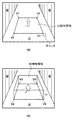
次に、2D領域設定部103は、画像データをモニタ212に表示して、2D検知領域を設定する(S102)。図4により画像データ、並びに、2Dおよび3D検知領域の例を示す。図4(a)の例において、画像データが表示された画面を観察するユーザは、操作部211により、画面に表示されたポインタを画面位置v1、v2、v3、v4に移動し、各画面位置v1、v2、v3、v4においてマウスボタンをクリックする。2D領域設定部103は、マウスボタンがクリックされた画面位置に対応する画像データの座標を、物体検知領域の基礎である2D検知領域の頂点座標として取得する。
Next, the 2D
図4(a)の例において、2D検知領域の頂点座標として{v1, v2, v3, v4}={(x1, y1),(x2, y2),(x3, y3),(x4, y4)}が取得される。2D領域設定部103は、取得した頂点座標が囲む多角形の領域を2D検知領域に設定する。なお、2D検知領域の設定は、上記方法に限らず、記憶部204やサーバ装置から2D検知領域を示す座標群を読み込む方法でもよい。また、図4には2D検知領域が四辺形の例を示すが、2D検知領域は多角形であればよい。
In the example of Fig. 4 (a), the vertex coordinates of the 2D detection area are {v1, v2, v3, v4} = {(x1, y1), (x2, y2), (x3, y3), (x4, y4) } Is obtained. The 2D
次に、距離画像取得部102は、測距装置221から距離データを取得する(S103)。距離データの取得は、測距装置221から奥行き方向の距離を取得して距離データとし、画像取得部101が取得した画像データと、画素ごとの対応付けを行う。
Next, the distance
測距装置221は、例えば、光の飛行時間をもとに距離を測定するTOF(Time-of-Flight)方式の原理に基づいて距離を測定する装置である。あるいは、測距装置221の方式として、複数のカメラの間の視差を基に距離を測定するステレオマッチング方式や、符号化パターンを投影して距離を得るパターン投光方式を用いることができる。
The
距離データと画像データの間の画素ごと対応付けは、監視カメラ220と測距装置221の間の相対的な回転および並進の情報を示す外部パラメータによって行われる。外部パラメータの算出は、例えば、自然特徴を用いて既知の方法により自動で算出してもよいし、監視カメラ220と測距装置221の設置間隔や俯角や設置高さを厳密に測定することで事前に求めてもよい。また、距離データの視野と画像データの視野は、完全に重畳する必要はなく、少なくとも物体検知領域において視野が重畳すればよい。
The correspondence between the distance data and the image data for each pixel is performed by an external parameter indicating information on relative rotation and translation between the monitoring
次に、点群取得部104は、2D検知領域の三次元位置を表す三次元点群を距離データから取得する(S104)。点群取得部104は、2D検知領域の画素(x, y)に対応する距離データの画素の距離zを取得することで、当該画素の三次元位置(x, y, z)を得る。例えば、図4に示す2D検知領域の頂点{v1, v2, v3, v4}について三次元位置{(x1, y1, z1),(x2, y2, z2),(x3, y3, z3),(x4, y4, z4)}が取得される。
Next, the point
取得される三次元点は、2D検知領域の頂点{v1, v2, v3, v4}に限らず、2D検知領域の各画素に対応する三次元点である。なお、距離zが得られない画素については三次元点の取得を除外する。また、2D検知領域のすべての画素に対応する三次元点群を取得する必要はなく、物体検知領域の精度に応じて2D検知領域の画素をサンプリングした一部の画素に対応する三次元点群を取得してもよい。 The acquired 3D points are not limited to the vertices {v1, v2, v3, v4} of the 2D detection area, but are 3D points corresponding to the respective pixels of the 2D detection area. Note that the acquisition of a three-dimensional point is excluded for pixels for which the distance z cannot be obtained. In addition, it is not necessary to acquire a 3D point cloud corresponding to all pixels in the 2D detection area, but a 3D point cloud corresponding to some pixels obtained by sampling the pixels in the 2D detection area according to the accuracy of the object detection area. May be obtained.
次に、平面推定部105は、三次元点群からランダムに複数の三次元点を選択し(S105)、選択三次元点に基づき、推定平面として三次元平面を算出する(S106)。なお、選択三次元点は三点以上あればよく、三点を超える場合は最小二乗法によって三次元平面を算出する。推定平面を二つのベクトル{p1, p2}で表す。
Next, the
次に、評価部106は、推定平面の平面らしさを示す評価値を算出する(S107)。評価部106は、三次元点群の各点と推定平面の間の距離を算出し、算出距離が所定の閾値以下の三次元点の数を評価値とする。閾値は、例えば3cmとするが、測距装置221の精度などに応じてユーザが適切な値を設定してもよい。
Next, the
次に、平面推定部105は、評価部106が出力する評価値に基づき、平面の推定を終了するか否かを判定する(S108)。例えば、比率R(=評価値/三次元点群の点数)が所定比率Rthを超える場合に終了と判定すればよい。あるいは、平面推定と評価が所定回数Nth(または所定時間Tth)繰り返された場合に終了と判定して、評価値が最大の推定平面を出力すればよい。平面の推定を終了しない場合、平面推定部105は、処理をステップS105に戻し、選択三次元点を更新して平面の推定を繰り返すが、その際、平面の推定に使用済みの三次元点の組み合わせが選択されないことは言うまでもない。
Next, the
平面の推定が終了すると、3D領域設定部107は、次の処理により3D検知領域を設定する。まず、推定平面を用いて、2D検知領域の三次元位置を修正する(S109)。続いて、カメラ座標系からワールド座標系への回転ベクトルRと並進ベクトルtを設定する(S110)。そして、修正後の2D検知領域をワールド座標系に変換し(S111)、変換後の2D検知領域に高さ情報Hを加える(S112)。これらの処理により、図4(b)に示す3D検知領域が設定される。
When the estimation of the plane is completed, the 3D
2D検知領域の三次元位置の修正(S109)を、図4に示す2D検知領域の頂点の三次元位置を用いて説明する。前述したように、2D検知領域の頂点{v1, v2, v3, v4}の三次元位置は{(x1, y1, z1),(x2, y2, z2),(x3, y3, z3),(x4, y4, z4)}である。3D領域設定部107は、推定平面を用いて2D検知領域の三次元位置の距離z1-z4を修正する。修正後の2D検知領域の三次元位置は、推定平面のベクトル{p1, p2}を用いて、下式によって算出される。
vn't = (xn', yn', zn')t
= A*(At*A)-1*At*(xn, yn, zn)t …(1)
ここで、A = (p1, p2)、
n=1、2、3、4。
The correction of the 3D position of the 2D detection area (S109) will be described using the 3D position of the vertex of the 2D detection area shown in FIG. As mentioned above, the 3D position of the vertex {v1, v2, v3, v4} of the 2D detection region is {(x1, y1, z1), (x2, y2, z2), (x3, y3, z3), ( x4, y4, z4)}. The 3D
vn ' t = (xn', yn ', zn') t
= A * (A t * A) -1 * A t * (xn, yn, zn) t … (1)
Where A = (p1, p2),
n = 1, 2, 3, 4.
つまり、ステップS109において、2D検知領域の頂点および頂点以外の三次元位置が推定平面に射影され、修正後の2D検知領域の三次元位置が得られる。修正後の2D検知領域の頂点{v1', v2', v3', v4'}の三次元位置を{(x1', y1', z1'),(x2', y2', z2'),(x3', y3', z3'),(x4', y4', z4')}で表す。 That is, in step S109, the vertex of the 2D detection area and the three-dimensional position other than the vertex are projected onto the estimation plane, and the corrected three-dimensional position of the 2D detection area is obtained. The three-dimensional positions of the vertices {v1 ', v2', v3 ', v4'} of the corrected 2D detection area are represented by {(x1 ', y1', z1 '), (x2', y2 ', z2'), ( x3 ′, y3 ′, z3 ′), (x4 ′, y4 ′, z4 ′)}.
ステップS110において、3D領域設定部107は、2D検知領域の上向きベクトルuとして推定平面に直交する方向のベクトルを設定する。そして、カメラ座標系からワールド座標系への変換式により、2D検知領域の上向きベクトルuとカメラ座標系の上向きベクトルcから、座標系の間の相対的な回転ベクトルRを算出する。また、カメラ座標系とワールド座標系の相対的な並進ベクトルtとして、2D検知領域の中心(平均)の三次元位置を設定する。
In step S110, the 3D
ステップS111において、3D領域設定部107は、回転ベクトルRと並進ベクトルtにより、修正後の2D検知領域をワールド座標系に変換する。修正後の2D検知領域の頂点{v1', v2', v3', v4'}は{V1, V2, V3, V4}={(X1, Y1, 0),(X2, Y2, 0),(X3, Y3, 0),(X4, Y4, 0)}に変換される。また、3D領域設定部107は、推定平面の上向きベクトルuを、下式により、ワールド座標系の2D検知領域の上向きベクトルU=(X, Y, Z)に変換する。
T = R*t
(X, Y, Z)t = R*{(x, y, z)t - t} + T …(2)
In step S111, the 3D
T = R * t
(X, Y, Z) t = R * {(x, y, z) t -t} + T… (2)
ステップS112において、3D領域設定部107は、上向きベクトルUに高さH(Uの大きさ)を与えて、3D検知領域{V1, V2, V3, V4, H}を設定する。高さHは、例えば、物体検知領域に侵入する人間を検知する場合は人間の身長をカバーする3mとするが、ユーザが任意に設定することができる。
In step S112, the 3D
物体検知処理に利用するために、3D領域設定部107は、カメラ座標系からワールド座標系への変換に必要な回転ベクトルRと並進ベクトルt、および、3D検知領域{V1, V2, V3, V4, H}を記憶部204などに格納する(S113)。
In order to use the object detection processing, the 3D
●物体検知処理
図5のフローチャートにより物体検知処理を説明する。物体検知処理は、物体検知装置として機能する情報処理装置200のCPU201によって実行される処理である。検知部108は、カメラ座標系からワールド座標系への変換に必要な回転ベクトルRと並進ベクトルt、および、3D検知領域{V1, V2, V3, V4, H}を記憶部204から取得する(S201)。
Object detection process The object detection process will be described with reference to the flowchart of FIG. The object detection process is a process executed by the
次に、検知部108は、距離画像取得部102から距離データを取得し(S202)、式(2)を用いて、距離データの三次元位置(x, y, z)をワールド座標系の三次元位置(X, Y, Z)に変換する(S203)。そして、検知部108は、ワールド座標系に変換した三次元位置が3D検知領域に存在するか否かに基づいて物体検知を行う。なお、距離データの全画素をワールド座標系に変換する必要はなく、検知精度に応じてサンプリングした画素をワールド座標系に変換してもよい。
Next, the
検知部108は、注目三次元位置の二次元座標(X, Y)が、3D検知領域の基礎内(例えば頂点{V1, V2, V3, V4}が構成する多角形内)に存在するか否かを判定する(S204)。判定には交差数判定(crossing number algorithm)を用いる。交差数判定は、判定対象の座標(以下、判定座標)を起点とする水平線が、多角形の辺と何回交差するかによって内外判定を行う。交差回数が奇数の場合、判定座標が多角形内に存在すると判定され、交差回数が偶数の場合、判定座標が多角形外に存在すると判定される。
The
次に、検知部108は、3D検知領域の高さHに基づき、基礎内に存在すると判定された二次元座標(X, Y)をもつ注目三次元位置(X, Y, Z)が3D検知領域に存在するか否かの判定を行う(S205)。注目三次元位置のZ座標が0<Z<Hを満たす場合、検知部108は、注目三次元位置が3D検知領域に存在すると判定し、注目三次元位置にラベル‘1’を付与する(S206)。
Next, the
一方、検知部108は、多角形外に存在すると判定した二次元座標(X, Y)をもつ注目三次元位置、または、3D検知領域外に存在すると判定した三次元位置にラベル‘0’を付与する(S207)。
On the other hand, the
次に、検知部108は、ワールド座標系に変換した三次元位置について、ステップS204からS207の処理が終了したか否かを判定し(S208)、未処理の三次元位置がある場合は処理をステップS204に戻す。
Next, the
検知部108がステップS204からS207の処理を繰り返すことで、測距装置221が取得した距離データの各画素についてラベリングが行われる。言い替えれば、検知部108は、距離データの画素が示す三次元位置をワールド座標系に変換し、変換後の三次元位置が3D検知領域に存在するか否かに応じて、距離データの各画素をラベリングする。その結果、ラベル‘1’が付与された三次元位置の集合として、3D検知領域に存在する物体が検知される。また、三次元位置に付与されたラベルがすべて‘0’の場合、3D検知領域に物体が存在しないことが検知されたことになる。
The
●侵入検知処理
図6のフローチャートにより侵入検知部109の処理を説明する。侵入検知処理は、物体検知装置として機能する情報処理装置200のCPU201によって実行される処理である。
Intrusion Detection Processing Processing of the
侵入検知部109は、検知部108からラベリングされた距離データ(以下、ラベリング距離データ)を取得する(S301)。そして、ラベリング距離データに基づき物体の三次元的な追跡を行う。前フレームの距離データの画素のラベルLpと、後フレームの距離データの対応する画素のラベルLcの組み合わせにより、各画素を次のように判定することができる。
Lp=‘0’かつLc=‘0’の画素:物体検知領域の基礎に相当する、
Lp=‘1’かつLc=‘1’の画素:物体検知領域に位置する物体に対応する、
Lp=‘0’かつLc=‘1’の画素:物体検知領域に侵入する物体に対応する、
Lp=‘1’かつLc=‘0’の画素:物体検知領域から退出する物体に対応する。
The
Lp = '0' and Lc = '0' pixels: equivalent to the basis of the object detection area,
Lp = '1' and Lc = '1' pixels: corresponding to objects located in the object detection area,
Lp = '0' and Lc = '1' pixels: corresponding to objects that enter the object detection area,
Pixel with Lp = '1' and Lc = '0': Corresponds to an object leaving the object detection area.
前フレームと後フレームは連続する二つのフレームに限らず、それらフレームの間に一つ以上のフレームが存在してもよく、時間が異なる複数のフレームであればよい。また、物体検知領域に侵入する物体に対応する画素(Lp=‘0’かつLc=‘1’)を「侵入物画素」、物体検知領域から退出する物体に対応する画素(Lp=‘1’かつLc=‘0’)を「退出物画素」と呼ぶ。 The previous frame and the subsequent frame are not limited to two consecutive frames, and one or more frames may exist between the frames, and any frame may be used as long as the time is different. Also, the pixel corresponding to the object entering the object detection area (Lp = '0' and Lc = '1') is the “intruder pixel”, and the pixel corresponding to the object leaving the object detection area (Lp = '1') Lc = '0') is referred to as a “leaved object pixel”.
侵入検知部109は、外乱やノイズの影響を避けるために、例えば、一つ前のフレームのラベリング距離データと現フレームのラベリング距離データから侵入物画素をカウントし(S302)、カウント値に基づき侵入検知を行う(S303)。例えば、カウント値が第一の所定数を超える場合、物体検知領域に物体が侵入したと判定し、侵入検知情報を出力する。
In order to avoid the influence of disturbance and noise, the
また、侵入検知に限らず、退出物体を検知する退出検知も可能である。つまり、侵入検知部109は、例えば、一つ前のフレームのラベリング距離データと現フレームのラベリング距離データから退出物画素をカウントし(S304)、カウント値に基づき退出検知を行う(S305)。例えば、カウント値が第二の所定数を超える場合、物体検知領域から物体が退出すると判定し、退出検知情報を出力する。
Further, not only intrusion detection but also exit detection that detects an exit object is possible. In other words, for example, the
侵入検知部109は、侵入/退出検知情報の出力として、侵入/退出検知結果をモニタ212に表示したり、モニタ212に表示された画像上に侵入/退出を検知した物体を示すマーカ表示などの処理を行う。また、ユーザ設定に応じて、侵入検知部109は、侵入/退出検知結果を記憶部204にログとして記録したりサーバ装置に通知したりする。
The
このように、距離データから取得した、2D検知領域に対応する三次元点群から平面を推定し、物体を検知する3D検知領域を設定する。従って、ユーザは2D検知領域を指定するだけであり、物体検知におけるユーザの操作性が向上し、物体を検知する3D検知領域の設定が容易になる。さらに、推定された平面は、三次元点群を用いて、その平面らしさが評価される。従って、3D検知領域の高精度な設定が可能になり、物体検知装置の精度向上する。 In this way, the plane is estimated from the three-dimensional point group corresponding to the 2D detection area acquired from the distance data, and the 3D detection area for detecting the object is set. Therefore, the user only specifies the 2D detection area, the user operability in object detection is improved, and the setting of the 3D detection area for detecting an object becomes easy. Furthermore, the estimated plane is evaluated for its flatness using a three-dimensional point group. Therefore, it is possible to set the 3D detection region with high accuracy, and the accuracy of the object detection device is improved.
[その他の実施例]
本発明は、上述の実施形態の一以上の機能を実現するプログラムを、ネットワーク又は記憶媒体を介してシステム又は装置に供給し、そのシステム又は装置のコンピュータにおける一以上のプロセッサがプログラムを読み出し実行する処理でも実現可能である。また、一以上の機能を実現する回路(例えば、ASIC)によっても実現可能である。
[Other Examples]
The present invention supplies a program that realizes one or more functions of the above-described embodiments to a system or apparatus via a network or a storage medium, and one or more processors in a computer of the system or apparatus read and execute the program It can also be realized by processing. It can also be realized by a circuit (for example, ASIC) that realizes one or more functions.
101 … 画像取得部、102 … 距離画像取得部、103 … 2D領域設定部、104 … 点群取得部、105 … 平面推定部、107 … 3D領域設定部
DESCRIPTION OF
Claims (15)
前記画像データに基づき、前記検知領域に対応する二次元領域を設定する第一の設定手段と、
前記二次元領域の三次元位置を表す三次元点群を前記距離データから取得する第二の取得手段と、
前記三次元点群に基づき、前記検知領域の基礎である平面を推定する推定手段と、
前記二次元領域および前記推定された平面に基づき、前記検知領域に対応する三次元領域を設定する第二の設定手段とを有する情報処理装置。 Image data including at least an image of the detection area, and first acquisition means for acquiring distance data indicating at least distance information of the detection area;
First setting means for setting a two-dimensional area corresponding to the detection area based on the image data;
Second acquisition means for acquiring a three-dimensional point group representing a three-dimensional position of the two-dimensional region from the distance data;
Based on the three-dimensional point group, estimating means for estimating a plane that is the basis of the detection region;
An information processing apparatus comprising: a second setting unit configured to set a three-dimensional area corresponding to the detection area based on the two-dimensional area and the estimated plane.
距離データを生成する測距部と、
請求項1から請求項11の何れか一項に記載された情報処理装置とを有する物体検知装置。 An imaging unit for imaging image data;
A distance measuring unit for generating distance data;
An object detection apparatus comprising: the information processing apparatus according to any one of claims 1 to 11.
第一の設定手段が、前記画像データに基づき、前記検知領域に対応する二次元領域を設定し、
第二の取得手段が、前記二次元領域の三次元位置を表す三次元点群を前記距離データから取得し、
推定手段が、前記三次元点群に基づき、前記検知領域の基礎である平面を推定し、
第二の設定手段が、前記二次元領域および前記推定された平面に基づき、前記検知領域に対応する三次元領域を設定する情報処理方法。 The first acquisition means acquires image data including at least an image of the detection area, and distance data indicating at least distance information of the detection area,
The first setting means sets a two-dimensional area corresponding to the detection area based on the image data,
A second acquisition unit acquires a three-dimensional point group representing a three-dimensional position of the two-dimensional region from the distance data;
An estimation means estimates a plane that is a basis of the detection region based on the three-dimensional point group,
An information processing method in which a second setting unit sets a three-dimensional area corresponding to the detection area based on the two-dimensional area and the estimated plane.
Priority Applications (1)
| Application Number | Priority Date | Filing Date | Title |
|---|---|---|---|
| JP2015217920A JP2017091063A (en) | 2015-11-05 | 2015-11-05 | Object detector, information processor, and method of the processor |
Applications Claiming Priority (1)
| Application Number | Priority Date | Filing Date | Title |
|---|---|---|---|
| JP2015217920A JP2017091063A (en) | 2015-11-05 | 2015-11-05 | Object detector, information processor, and method of the processor |
Publications (1)
| Publication Number | Publication Date |
|---|---|
| JP2017091063A true JP2017091063A (en) | 2017-05-25 |
Family
ID=58771751
Family Applications (1)
| Application Number | Title | Priority Date | Filing Date |
|---|---|---|---|
| JP2015217920A Pending JP2017091063A (en) | 2015-11-05 | 2015-11-05 | Object detector, information processor, and method of the processor |
Country Status (1)
| Country | Link |
|---|---|
| JP (1) | JP2017091063A (en) |
Cited By (8)
| Publication number | Priority date | Publication date | Assignee | Title |
|---|---|---|---|---|
| CN111009089A (en) * | 2019-11-25 | 2020-04-14 | 国网安徽省电力有限公司建设分公司 | Virtual fence system and control method for power grid infrastructure site based on RGB-D camera |
| CN111507938A (en) * | 2020-03-10 | 2020-08-07 | 博微太赫兹信息科技有限公司 | Human body dangerous article detection method and system |
| JP2020135076A (en) * | 2019-02-13 | 2020-08-31 | Necソリューションイノベータ株式会社 | Face direction detector, face direction detection method, and program |
| CN114450714A (en) * | 2019-09-24 | 2022-05-06 | 京瓷株式会社 | Object detection device, object detection system, moving body, and object detection method |
| JP2022110291A (en) * | 2021-01-18 | 2022-07-29 | ピクシーダストテクノロジーズ株式会社 | Information processing device, information processing method, and program |
| CN115479538A (en) * | 2021-05-31 | 2022-12-16 | 精工爱普生株式会社 | Detection method and detection system |
| WO2024070751A1 (en) * | 2022-09-30 | 2024-04-04 | ソニーセミコンダクタソリューションズ株式会社 | Image processing device, image processing method, and program |
| CN119477177A (en) * | 2025-01-13 | 2025-02-18 | 江苏博然智能科技有限公司 | A water station information data processing method and system |
-
2015
- 2015-11-05 JP JP2015217920A patent/JP2017091063A/en active Pending
Cited By (12)
| Publication number | Priority date | Publication date | Assignee | Title |
|---|---|---|---|---|
| JP2020135076A (en) * | 2019-02-13 | 2020-08-31 | Necソリューションイノベータ株式会社 | Face direction detector, face direction detection method, and program |
| JP7279892B2 (en) | 2019-02-13 | 2023-05-23 | Necソリューションイノベータ株式会社 | FACE POSITION DETECTION DEVICE, FACE POSITION DETECTION METHOD, AND PROGRAM |
| CN114450714A (en) * | 2019-09-24 | 2022-05-06 | 京瓷株式会社 | Object detection device, object detection system, moving body, and object detection method |
| CN111009089A (en) * | 2019-11-25 | 2020-04-14 | 国网安徽省电力有限公司建设分公司 | Virtual fence system and control method for power grid infrastructure site based on RGB-D camera |
| CN111009089B (en) * | 2019-11-25 | 2024-02-13 | 国网安徽省电力有限公司建设分公司 | Power grid infrastructure site virtual fence system and its control method based on RGB-D camera |
| CN111507938A (en) * | 2020-03-10 | 2020-08-07 | 博微太赫兹信息科技有限公司 | Human body dangerous article detection method and system |
| CN111507938B (en) * | 2020-03-10 | 2023-04-21 | 博微太赫兹信息科技有限公司 | Human body dangerous goods detection method and system |
| JP2022110291A (en) * | 2021-01-18 | 2022-07-29 | ピクシーダストテクノロジーズ株式会社 | Information processing device, information processing method, and program |
| JP7344570B2 (en) | 2021-01-18 | 2023-09-14 | ピクシーダストテクノロジーズ株式会社 | Information processing device, information processing method, and program |
| CN115479538A (en) * | 2021-05-31 | 2022-12-16 | 精工爱普生株式会社 | Detection method and detection system |
| WO2024070751A1 (en) * | 2022-09-30 | 2024-04-04 | ソニーセミコンダクタソリューションズ株式会社 | Image processing device, image processing method, and program |
| CN119477177A (en) * | 2025-01-13 | 2025-02-18 | 江苏博然智能科技有限公司 | A water station information data processing method and system |
Similar Documents
| Publication | Publication Date | Title |
|---|---|---|
| JP2017091063A (en) | Object detector, information processor, and method of the processor | |
| US8988317B1 (en) | Depth determination for light field images | |
| EP3016071B1 (en) | Estimating device and estimation method | |
| US10638115B2 (en) | Calibration device | |
| JP6712778B2 (en) | Object detection device, object detection system, and object detection method | |
| CN103377471B (en) | Object positioning method and device, optimum video camera are to determining method and apparatus | |
| TWI696906B (en) | Method for processing a floor | |
| EP3153990A1 (en) | Display control apparatus, display control method, and program | |
| WO2019225547A1 (en) | Object tracking device, object tracking method, and object tracking program | |
| TW201616451A (en) | System and method for selecting point clouds using a free selection tool | |
| EP4220547B1 (en) | Method and apparatus for determining heat data of global region, and storage medium | |
| US20170109932A1 (en) | Content projection apparatus, content projection method, and computer readable storage medium | |
| EP2372652B1 (en) | Method for estimating a plane in a range image and range image camera | |
| JP2017032335A (en) | Information processing apparatus, information processing method, and program | |
| JP2016099316A (en) | Feature change discrimination method, feature change discrimination device, and feature change discrimination program | |
| KR101330531B1 (en) | Method of virtual touch using 3D camera and apparatus thereof | |
| CN109961472A (en) | Method, system, storage medium and electronic device for generating 3D heat map | |
| US20130050483A1 (en) | Apparatus, method, and program for video surveillance system | |
| US20160140736A1 (en) | Viewpoint position calculation device, image generation device, and viewpoint position calculation method | |
| KR101620580B1 (en) | Method and system for dectecting run | |
| EP3147864A2 (en) | Position estimating device and position estimating method | |
| KR102540676B1 (en) | Method and System for Derive the Position of an Object Using a Camera Image | |
| JP5727969B2 (en) | Position estimation apparatus, method, and program | |
| US10019635B2 (en) | Vehicle-mounted recognition device | |
| JP2018063675A (en) | Image processing apparatus and control method |