JP2017063508A - Terminal device, base station device, communication method, and integrated circuit - Google Patents
Terminal device, base station device, communication method, and integrated circuit Download PDFInfo
- Publication number
- JP2017063508A JP2017063508A JP2017002897A JP2017002897A JP2017063508A JP 2017063508 A JP2017063508 A JP 2017063508A JP 2017002897 A JP2017002897 A JP 2017002897A JP 2017002897 A JP2017002897 A JP 2017002897A JP 2017063508 A JP2017063508 A JP 2017063508A
- Authority
- JP
- Japan
- Prior art keywords
- pdcch
- terminal
- control channel
- downlink control
- physical downlink
- Prior art date
- Legal status (The legal status is an assumption and is not a legal conclusion. Google has not performed a legal analysis and makes no representation as to the accuracy of the status listed.)
- Pending
Links
Images


Landscapes
- Mobile Radio Communication Systems (AREA)
Abstract
Description
本発明は、端末装置、基地局装置、通信方法および集積回路に関する。 The present invention relates to a terminal device, a base station device, a communication method, and an integrated circuit.
3GPP(Third Generation Partnership Project)によるLTE(Long Term Evolution)、LTE−A(LTE−Advanced)やIEEE(The Institute of Electrical and Electronics engineers)によるWireless LAN、WiMAX(Worldwide Interoperability for Microwave Access)のような無線通信システムでは、基地局(基地局装置、下りリンク送信装置、上りリンク受信装置、eNodeB)および端末(端末装置、移動局装置、下りリンク受信装置、上りリンク送信装置、ユーザ装置、UE)は、複数の送受信アンテナをそれぞれ備え、MIMO(Multi Input Multi Output)技術を用いることにより、データ信号を空間多重し、高速なデータ通信を実現する。また、特に、LTEおよびLTE−Aでは、下りリンクでOFDM(Orthogonal Frequency Division Multiplexing)方式を用いて高い周波数利用効率を実現するとともに、上りリンクでSC−FDMA(Single Carrier−Frequency Division Multiple Access)方式を用いてピーク電力を抑制している。 3GPP (Third Generation Partnership Project) in due LTE (Long Term Evolution), LTE-A (LTE-Advanced) and IEEE (The Institute of Electrical and Electronics engineers) in due Wireless LAN, wireless such as WiMAX (Worldwide Interoperability for Microwave Access) In the communication system, a base station (base station apparatus, downlink transmission apparatus, uplink reception apparatus, eNodeB) and terminal (terminal apparatus, mobile station apparatus, downlink reception apparatus, uplink transmission apparatus, user apparatus, UE) are: Each has a plurality of transmitting and receiving antennas, M By using the MO (Multi Input Multi Output) technology, a data signal spatially multiplexed to achieve high-speed data communications. In particular, in LTE and LTE-A, high frequency utilization efficiency is achieved using OFDM (Orthogonal Frequency Division Multiplexing) in the downlink, and SC-FDMA (Single Carrier-Frequency Multiplexing cc) in the uplink. Is used to suppress the peak power.
図21は、LTEの通信システム構成を示す図である。図21では、基地局2101は端末2102に、物理下りリンク制御チャネル(PDCCH:Pysical Downlink Control CHannel)を用いて下りリンク送信データ2104に関する制御情報の通知を行う。このとき、共通探索領域にPDCCH2103を配置することもできるし、端末固有探索領域にPDCCH2104を配置することもできる。共通探索領域と端末固有探索領域とは、ともにサブフレームの先頭から所定数のOFDMシンボル上で規定される(非特許文献1、非特許文献2)。
FIG. 21 is a diagram illustrating an LTE communication system configuration. In FIG. 21, the
しかしながら、1つの基地局が収容できる端末の数を増加するために、物理下りリンク制御チャネルだけでなく、拡張された物理下りリンク制御チャネルを用いることが考えられる。この拡張された物理下りリンク制御チャネルは、必ずしもサブフレームの先頭のOFDMシンボル上に規定されない。そのため、従来の方法では、探索領域の位置を基地局と端末との間で共通に設定することができず、伝送効率の向上が妨げられる要因となる。 However, in order to increase the number of terminals that can be accommodated by one base station, it is conceivable to use an extended physical downlink control channel as well as a physical downlink control channel. This extended physical downlink control channel is not necessarily defined on the first OFDM symbol of the subframe. Therefore, in the conventional method, the position of the search area cannot be set in common between the base station and the terminal, which is a factor that hinders improvement in transmission efficiency.
本発明は、上記問題を鑑みてなされたものであり、その目的は、基地局と端末が通信する無線通信システムにおいて、基地局が端末に対する制御情報を、物理下りリンク制御チャネルだけでなく、拡張された物理下りリンク制御チャネルを介して通知する場合においても、効率的に探索領域の位置を設定することができる端末装置、基地局装置、通信方法および集積回路を提供することにある。 The present invention has been made in view of the above problems, and an object of the present invention is to extend not only a physical downlink control channel but also control information for a terminal in a wireless communication system in which the base station and the terminal communicate with each other. An object of the present invention is to provide a terminal device, a base station device, a communication method, and an integrated circuit that can efficiently set the position of a search region even when notification is made via a physical downlink control channel.
(1)この発明は上述した課題を解決するためになされたもので、本発明の一態様による端末装置は、基地局装置と通信する端末装置であって、第1の報知情報を伝送する第1の物理チャネルであって、6個のリソースブロックにより配置される第1の物理チャネルを受信し、拡張物理下りリンク制御チャネル用共通探索領域内の拡張物理下りリンク制御チャネルをモニタし、前記拡張物理下りリンク制御チャネルのOFDMシンボルの開始位置である第1の開始位置は、前記第1の報知情報により指示され、前記拡張物理下りリンク制御チャネルは、ページングに関する拡張物理下りリンク制御チャネルである。 (1) The present invention has been made to solve the above-described problem, and a terminal apparatus according to an aspect of the present invention is a terminal apparatus that communicates with a base station apparatus, and transmits first broadcast information. 1 physical channel, the first physical channel arranged by 6 resource blocks is received, the extended physical downlink control channel in the common search area for the extended physical downlink control channel is monitored, and the extended The first start position, which is the OFDM symbol start position of the physical downlink control channel, is indicated by the first broadcast information, and the extended physical downlink control channel is an extended physical downlink control channel related to paging.
(2)また、この発明の他の態様は、上述した端末装置であって、前記第1の物理チャネルは、物理報知チャネルとは異なる。 (2) Moreover, the other aspect of this invention is the terminal device mentioned above, Comprising: The said 1st physical channel differs from a physical alerting | reporting channel.
(3)また、この発明の他の態様は、上述した端末装置であって、トランスポートブロックを伝送する物理下りリンク共用チャネルを、OFDMシンボルの第2の開始位置を用いて受信する。 (3) Moreover, the other aspect of this invention is the terminal device mentioned above, Comprising: The physical downlink shared channel which transmits a transport block is received using the 2nd start position of an OFDM symbol.
(4)また、この発明の他の態様による基地局装置は、端末装置と通信する基地局装置であって、第1の報知情報を伝送する第1の物理チャネルであって、6個のリソースブロックにより配置される第1の物理チャネルを送信し、拡張物理下りリンク制御チャネル用共通探索領域内の拡張物理下りリンク制御チャネルを送信し、前記拡張物理下りリンク制御チャネルのOFDMシンボルの開始位置である第1の開始位置を、前記第1の報知情報により指示され、前記拡張物理下りリンク制御チャネルは、ページングに関する拡張物理下りリンク制御チャネルである。 (4) A base station apparatus according to another aspect of the present invention is a base station apparatus that communicates with a terminal apparatus, is a first physical channel that transmits first broadcast information, and includes six resources. Transmitting the first physical channel arranged by the block, transmitting the extended physical downlink control channel in the common search area for the extended physical downlink control channel, and at the OFDM symbol start position of the extended physical downlink control channel A certain first start position is indicated by the first broadcast information, and the extended physical downlink control channel is an extended physical downlink control channel related to paging.
(5)また、この発明の他の態様は、上述した基地局装置であって、前記第1の物理チャネルは、物理報知チャネルとは異なる。 (5) Moreover, the other aspect of this invention is the base station apparatus mentioned above, Comprising: The said 1st physical channel differs from a physical alerting | reporting channel.
(6)また、この発明の他の態様は、上述した基地局装置であって、トランスポートブロックを伝送する物理下りリンク共用チャネルを、OFDMシンボルの第2の開始位置を用いて送信する。 (6) Moreover, the other aspect of this invention is the base station apparatus mentioned above, Comprising: The physical downlink shared channel which transmits a transport block is transmitted using the 2nd start position of an OFDM symbol.
(7)また、この発明の他の態様による通信方法は、基地局装置と通信する端末装置の通信方法であって、第1の報知情報を伝送する第1の物理チャネルであって、6個のリソースブロックにより配置される第1の物理チャネルを受信する過程と、拡張物理下りリンク制御チャネル用共通探索領域内の拡張物理下りリンク制御チャネルをモニタする過程とを有し、前記拡張物理下りリンク制御チャネルのOFDMシンボルの開始位置である第1の開始位置は、前記第1の報知情報により指示され、前記拡張物理下りリンク制御チャネルは、ページングに関する拡張物理下りリンク制御チャネルである。 (7) A communication method according to another aspect of the present invention is a communication method of a terminal device that communicates with a base station device, and is a first physical channel that transmits first broadcast information, and includes six communication methods. Receiving the first physical channel arranged by the resource block, and monitoring the extended physical downlink control channel in the common search area for the extended physical downlink control channel, the extended physical downlink The first start position, which is the start position of the OFDM symbol of the control channel, is indicated by the first broadcast information, and the extended physical downlink control channel is an extended physical downlink control channel related to paging.
(8)また、この発明の他の態様による通信方法は、端末装置と通信する基地局装置の通信方法であって、第1の報知情報を伝送する第1の物理チャネルであって、6個のリソースブロックにより配置される第1の物理チャネルを送信する過程と、拡張物理下りリンク制御チャネル用共通探索領域内の拡張物理下りリンク制御チャネルを送信する過程とを有し、前記拡張物理下りリンク制御チャネルのOFDMシンボルの開始位置である第1の開始位置は、前記第1の報知情報により指示され、前記拡張物理下りリンク制御チャネルは、ページングに関する拡張物理下りリンク制御チャネルである。 (8) A communication method according to another aspect of the present invention is a communication method of a base station device that communicates with a terminal device, and is a first physical channel that transmits first broadcast information, and includes six communication methods. And transmitting a first physical channel arranged by resource blocks of the first physical channel and a process of transmitting an extended physical downlink control channel in the common search area for the extended physical downlink control channel, the extended physical downlink The first start position, which is the start position of the OFDM symbol of the control channel, is indicated by the first broadcast information, and the extended physical downlink control channel is an extended physical downlink control channel related to paging.
(9)また、この発明の他の態様による集積回路は、基地局装置と通信する端末装置に搭載可能な集積回路であって、第1の報知情報を伝送する第1の物理チャネルであって、6個のリソースブロックにより配置される第1の物理チャネルを受信する処理部を備え、前記処理部は、拡張物理下りリンク制御チャネル用共通探索領域内の拡張物理下りリンク制御チャネルをモニタし、前記拡張物理下りリンク制御チャネルのOFDMシンボルの開始位置である第1の開始位置は、前記第1の報知情報により指示され、前記拡張物理下りリンク制御チャネルは、ページングに関する拡張物理下りリンク制御チャネルである。 (9) An integrated circuit according to another aspect of the present invention is an integrated circuit that can be mounted on a terminal device that communicates with a base station device, and is a first physical channel that transmits first broadcast information. , A processing unit that receives a first physical channel arranged by six resource blocks, the processing unit monitoring the extended physical downlink control channel in the common search area for the extended physical downlink control channel, A first start position that is an OFDM symbol start position of the enhanced physical downlink control channel is indicated by the first broadcast information, and the enhanced physical downlink control channel is an enhanced physical downlink control channel related to paging. is there.
(10)また、この発明の他の態様による集積回路は、端末装置と通信する基地局装置に搭載可能な集積回路であって、第1の報知情報を伝送する第1の物理チャネルであって、6個のリソースブロックにより配置される第1の物理チャネルを送信する処理部を備え、前記処理部は、拡張物理下りリンク制御チャネル用共通探索領域内の拡張物理下りリンク制御チャネルを送信し、前記拡張物理下りリンク制御チャネルのOFDMシンボルの開始位置である第1の開始位置は、前記第1の報知情報により指示され、前記拡張物理下りリンク制御チャネルは、ページングに関する拡張物理下りリンク制御チャネルである。 (10) An integrated circuit according to another aspect of the present invention is an integrated circuit that can be mounted on a base station device that communicates with a terminal device, and is a first physical channel that transmits first broadcast information. , A processing unit that transmits a first physical channel arranged by six resource blocks, the processing unit transmitting an extended physical downlink control channel in the common search area for the extended physical downlink control channel, A first start position that is an OFDM symbol start position of the enhanced physical downlink control channel is indicated by the first broadcast information, and the enhanced physical downlink control channel is an enhanced physical downlink control channel related to paging. is there.
この発明によれば、基地局と端末が通信する無線通信システムにおいて、基地局が端末に対する制御情報を、物理下りリンク制御チャネルだけでなく、拡張された物理下りリンク制御チャネルを介して通知する場合においても、効率的に探索領域の位置を設定することができる。 According to the present invention, in a wireless communication system in which a base station and a terminal communicate, the base station notifies control information for the terminal not only through a physical downlink control channel but also through an extended physical downlink control channel. The position of the search area can be set efficiently.
(第1の実施形態)
以下、本発明の第1の実施形態について説明する。本第1の実施形態における通信システムは、基地局(基地局装置、下りリンク送信装置、上りリンク受信装置、eNodeB)および端末(端末装置、移動局装置、下りリンク受信装置、上りリンク送信装置、ユーザ装置、UE)を備える。
(First embodiment)
Hereinafter, a first embodiment of the present invention will be described. The communication system in the first embodiment includes a base station (base station apparatus, downlink transmission apparatus, uplink reception apparatus, eNodeB) and terminal (terminal apparatus, mobile station apparatus, downlink reception apparatus, uplink transmission apparatus, A user equipment, UE).
図1は、第1の実施形態に係る通信システム構成例を示す図である。図1では、基地局101は端末102に、拡張された物理下りリンク制御チャネルである拡張物理下りリンク制御チャネル(E−PDCCH:Enhanced−PDCCH)を用いて、下りリンク送信データ104に関する制御情報の通知を行う。端末102は、制御情報の検出を試行し、検出された場合に、検出された制御情報を用いて下りリンク送信データ104を抽出する。ここで、端末102がE−PDCCHの検出試行を行う領域である探索領域は、端末固有のシグナリングに依存しないで決定される探索領域である共通探索領域と、端末固有のシグナリングに依存して決定される探索領域である端末固有探索領域とに分類される。基地局101は、共通探索領域および/または端末固有探索領域にE−PDCCHを配置して送信し、端末102は、共通探索領域におけるE−PDCCH103および/または端末固有探索領域におけるE−PDCCH104の検出試行を行う。なお、共通探索領域および端末固有探索領域の詳細に関しては後述する。一方、基地局101は、E−PDCCHを用いる端末102と同時に、PDCCHを用いる端末106を収容することができる。基地局は101は、端末102にE−PDCCHを送信するのと同じサブフレームで、端末106にPDCCH107を送信する。なお、端末102もPDCCH107を受信する機能を有してもよい。
FIG. 1 is a diagram illustrating a configuration example of a communication system according to the first embodiment. In FIG. 1, the
図2は、本実施形態に係る下りリンクの無線フレーム構成の一例を示す図である。下りリンクはOFDMアクセス方式が用いられる。下りリンクでは、PDCCH、物理下りリンク共用チャネル(PDSCH;Physical Downlink SharedCHannel)、物理報知チャネル(PBCH;Physical Broadcast Channel)、物理制御フォーマット指標チャネル(PCFICH;Physical Control Format Indicator Channel)などが割り当てられる。下りリンクの無線フレームは、下りリンクのリソースブロック(RB;Resource Block)ペアから構成されている。この下りリンクのRBペアは、下りリンクの無線リソースの割り当てなどの単位であり、予め決められた幅の周波数帯(RB帯域幅)及び時間帯(2個のスロット=1個のサブフレーム)からなる。1個の下りリンクのRBペアは、時間領域で連続する2個の下りリンクのRB(RB帯域幅×スロット)から構成される。1個の下りリンクのRBは、周波数領域において12個のサブキャリアから構成され、時間領域において7個のOFDMシンボルから構成される。周波数領域において1つのサブキャリア、時間領域において1つのOFDMシンボルにより規定される領域をリソースエレメント(RE;Resource Element)と称する。物理下りリンク制御チャネルは、端末装置識別子、物理下りリンク共用チャネルのスケジューリング情報、物理上りリンク共用チャネルのスケジューリング情報、変調方式、符号化率、再送パラメータなどの下りリンク制御情報が送信される物理チャネルである。なお、ここでは一つの要素キャリア(CC;Component Carrier)における下りリンクサブフレームを記載しているが、CC毎に下りリンクサブフレームが規定され、下りリンクサブフレームはCC間でほぼ同期している。 FIG. 2 is a diagram illustrating an example of a downlink radio frame configuration according to the present embodiment. An OFDM access scheme is used for the downlink. In downlink, PDCCH, physical downlink shared channel (PDSCH; Physical Downlink Shared Channel), physical broadcast channel (PBCH; Physical Broadcast Channel), physical control format index channel (PCFICH; Physical Control Inform, etc.). The downlink radio frame is composed of a downlink resource block (RB) pair. This downlink RB pair is a unit such as downlink radio resource allocation, and is based on a predetermined frequency band (RB bandwidth) and time band (2 slots = 1 subframe). Become. One downlink RB pair is composed of two downlink RBs (RB bandwidth × slot) that are continuous in the time domain. One downlink RB is composed of 12 subcarriers in the frequency domain, and is composed of 7 OFDM symbols in the time domain. A region defined by one subcarrier in the frequency domain and one OFDM symbol in the time domain is referred to as a resource element (RE). The physical downlink control channel is a physical channel through which downlink control information such as a terminal device identifier, physical downlink shared channel scheduling information, physical uplink shared channel scheduling information, modulation scheme, coding rate, and retransmission parameter is transmitted. It is. In addition, although the downlink sub-frame in one element carrier (CC; Component Carrier) is described here, a downlink sub-frame is prescribed | regulated for every CC, and a downlink sub-frame is substantially synchronized between CC. .
PDCCHは、サブフレーム内の先頭部分に位置する所定数のOFDMシンボル上に割り当てられる。PDSCHは、PDCCHが割り当てられるOFDMシンボルよりも後方部分に位置するOFDMシンボル上に割り当てられる。PBCHは、システム帯域(CCの帯域)の中心に位置する6リソースブロックペアにおける第2スロットに割り当てられる。また、PBCHは10サブフレーム周期で配置される。PCFICHは、サブフレーム内の先頭のOFDMシンボル上に離散的に割り当てられる。PBCHおよびPCFICHは、端末専用(端末固有)のシグナリングを行うことなく、いずれの端末も受信することができる。 The PDCCH is allocated on a predetermined number of OFDM symbols located at the head portion in the subframe. The PDSCH is allocated on the OFDM symbol located in the rear part of the OFDM symbol to which the PDCCH is allocated. The PBCH is allocated to the second slot in the 6 resource block pair located at the center of the system band (CC band). Moreover, PBCH is arrange | positioned with a 10 sub-frame period. PCFICH is assigned discretely on the first OFDM symbol in the subframe. PBCH and PCFICH can be received by any terminal without performing terminal-specific (terminal-specific) signaling.
図3は、本実施形態に係る上りリンクの無線フレーム構成の一例を示す図である。上りリンクはSC−FDMA方式が用いられる。上りリンクでは、物理上りリンク共用チャネル(Physical Uplink Shared Channel;PUSCH)、PUCCHなどが割り当てられる。また、PUSCHやPUCCHの一部に、上りリンク参照信号が割り当てられる。上りリンクの無線フレームは、上りリンクのRBペアから構成されている。この上りリンクのRBペアは、上りリンクの無線リソースの割り当てなどの単位であり、予め決められた幅の周波数帯(RB帯域幅)及び時間帯(2個のスロット=1個のサブフレーム)からなる。1個の上りリンクのRBペアは、時間領域で連続する2個の上りリンクのRB(RB帯域幅×スロット)から構成される。1個の上りリンクのRBは、周波数領域において12個のサブキャリアから構成され、時間領域において7個のSC−FDMAシンボルから構成される。なお、ここでは一つのCCにおける上りリンクサブフレームを記載しているが、CC毎に上りリンクサブフレームが規定される。 FIG. 3 is a diagram illustrating an example of an uplink radio frame configuration according to the present embodiment. The SC-FDMA scheme is used for the uplink. In the uplink, a physical uplink shared channel (PUSCH), PUCCH, and the like are allocated. Further, an uplink reference signal is assigned to a part of PUSCH or PUCCH. The uplink radio frame is composed of uplink RB pairs. This uplink RB pair is a unit for allocation of uplink radio resources and the like, and is based on a predetermined frequency band (RB bandwidth) and time band (2 slots = 1 subframe). Become. One uplink RB pair is composed of two uplink RBs (RB bandwidth × slot) that are continuous in the time domain. One uplink RB is composed of 12 subcarriers in the frequency domain, and is composed of 7 SC-FDMA symbols in the time domain. Here, although an uplink subframe in one CC is described, an uplink subframe is defined for each CC.
図4は、本実施形態に係る基地局101のブロック構成の一例を示す概略図である。基地局101は、コードワード生成部401、下りリンクサブフレーム生成部402、OFDM信号送信部(下りリンク制御チャネル送信部)404、送信アンテナ(基地局送信アンテナ)405、受信アンテナ(基地局受信アンテナ)406、SC−FDMA信号受信部407、上りリンクサブフレーム処理部408、上位層(上位層制御情報通知部)409を有する。下りリンクサブフレーム生成部402は、物理下りリンク制御チャネル生成部403を有する。
FIG. 4 is a schematic diagram illustrating an example of a block configuration of the
図5は、本実施形態に係る端末102のブロック構成の一例を示す概略図である。端末102は、受信アンテナ(端末受信アンテナ)501、OFDM信号受信部(下りリンク受信部)502、下りリンクサブフレーム処理部503、コードワード抽出部(データ抽出部)505、上位層(上位層制御情報取得部)506、上りリンクサブフレーム生成部507、SC−FDMA信号送信部508、送信アンテナ(端末送信アンテナ)509を有する。下りリンクサブフレーム処理部503は、物理下りリンク制御チャネル抽出部(下りリンク制御チャネル検出部)504を有する。
FIG. 5 is a schematic diagram illustrating an example of a block configuration of the terminal 102 according to the present embodiment. The terminal 102 includes a receiving antenna (terminal receiving antenna) 501, an OFDM signal receiving unit (downlink receiving unit) 502, a downlink
まず、図4および図5を用いて、下りリンクデータの送受信の流れについて説明する。基地局101では、上位層409から送られてくる送信データ(トランスポートブロックとも称す)は、コードワード生成部401において、誤り訂正符号化、レートマッチング処理などの処理が施され、コードワードが生成される。この下りリンク送信データは、端末102宛の送信データである場合もあれば、ページングやシステム情報など、複数の端末に共通の送信データである場合もある。1つのセルにおける1つのサブフレームにおいて、最大2つのコードワードが同時に送信される。下りリンクサブフレーム生成部402では、上位層409の指示により、下りリンクサブフレームが生成される。まず、コードワード生成部401において生成されたコードワードは、PSK(Phase Shift Keying)変調やQAM(Quadrature Amplitude Modulation)変調などの変調処理により、変調シンボル系列に変換される。また、変調シンボル系列は、一部のRB内のREにマッピングされ、プレコーディング処理によりアンテナポート毎の下りリンクサブフレームが生成される。なお、下りリンクにおけるREは、各OFDMシンボル上の各サブキャリアに対応して規定される。このとき、上位層409から送られてくる送信データ系列は、RRC(Radio Resource Control)シグナリング用の制御情報(上位層制御情報)を含む。また、物理下りリンク制御チャネル生成部403では、物理下りリンク制御チャネルが生成される。ここで、物理下りリンク制御チャネルに含まれる制御情報(下りリンク制御情報、下りリンクグラント)は、下りリンクにおける変調方式などを示すMCS(Modulation and Coding Scheme)、データ送信に用いるRBを示す下りリンクリソース割り当て、HARQの制御に用いるHARQの制御情報(リダンダンシーバージョン・HARQプロセス番号・新データ指標)、PUCCHの閉ループ送信電力制御に用いるPUCCH−TPC(Transmission Power Control)コマンドなどの情報を含む。また、物理下りリンク制御チャネル生成部403は、CFI(Control Format Indicator)などを特定する物理報知チャネルPBCHやPCFICHを生成する機能も有する。下りリンクサブフレーム生成部402は、上位層410の指示により、また、下りリンク送信データの種類に応じたRNTI(Radio Network Temporary ID)でマスクし、物理下りリンク制御チャネルを下りリンクサブフレーム内のREにマッピングする。物理下りリンク制御チャネルがマッピングされるREは、探索領域を構成するREである。物理下りリンク制御チャネルは、共通探索領域を構成するREあるいは端末固有探索領域を構成するREにマッピングされる。下りリンクサブフレーム生成部402で生成されたアンテナポート毎の下りリンクサブフレームは、OFDM信号送信部404においてOFDM信号に変調され、送信アンテナ405を介して送信される。
First, the flow of downlink data transmission / reception will be described using FIG. 4 and FIG. In the
端末102では、受信アンテナ501を介して、OFDM信号受信部502においてOFDM信号が受信され、OFDM復調処理が施される。下りリンクサブフレーム処理部503は、まず物理下りリンク制御チャネル抽出部504においてPDCCH(第1の下りリンク制御チャネル)あるいはE−PDCCH(第2の下りリンク制御チャネル)を検出する。より具体的には、PDCCHが配置され得る領域(第1の下りリンク制御チャネル領域)あるいはE−PDCCHが配置され得る領域(第2の下りリンク制御チャネル領域、潜在的E−PDCCH)をデコードし、予め付加されているCRCの検査ビットを確認する(ブラインドデコーディング)。すなわち、物理下りリンク制御チャネル抽出部504は、共通探索領域および/または端末固有探索領域に配置されたE−PDCCHをモニタリングする。また、PBCHやPCFICHを抽出し、CFIを取得する機能も有する。CRC検査ビットが予め基地局から割り当てられたID(RNTI)と一致する場合、下りリンクサブフレーム処理部503は、PDCCHあるいはE−PDCCHを検出できたものと認識し、検出したPDCCHあるいはE−PDCCHに含まれる制御情報を用いてPDSCHを抽出する。より具体的には、下りリンクサブフレーム生成部402におけるREマッピング処理や変調処理に対応するREデマッピング処理や復調処理などが施される。受信した下りリンクサブフレームから抽出されたPDSCHは、コードワード抽出部505に送られる。コードワード抽出部505では、コードワード生成部401におけるレートマッチング処理、誤り訂正符号化に対応するレートマッチング処理、誤り訂正復号化などが施され、トランスポートブロックが抽出され、上位層506に送られる。すなわち、物理下りリンク制御チャネル抽出部504がPDCCHあるいはE−PDCCHを検出した場合、コードワード抽出部505は検出されたPDCCHあるいはE−PDCCHに関連するPDSCHにおける送信データを抽出して上位層506に送る。
In
次に、上りリンク送信データの送受信の流れについて説明する。端末102では、上りリンクサブフレーム生成部507では、上位層506から送られる上りリンク送信データが、上りリンクサブフレーム内のRBにマッピングされる。SC−FDMA信号送信部508は、上りリンクサブフレームにSC−FDMA変調を施してSC−FDMA信号を生成し、送信アンテナ509を介して送信する。
Next, a flow of transmission / reception of uplink transmission data will be described. In
基地局101では、受信アンテナ406を介して、SC−FDMA信号受信部407においてSC−FDMA信号が受信され、SC−FDMA復調処理が施される。上りリンクサブフレーム処理部408では、上りリンク送信データがマッピングされたRBから上りリンク送信データを抽出し、抽出された上りリンク送信データは上位層409に送られる。
In the
ここで、CFIについて説明する。PCFICHにより指定されるCFIは通常、PDCCHが割り当てられるOFDMシンボルの数を示す。また、これに伴い、PCFICHにより指定されるCFIはPDSCHの開始位置となるOFDMシンボルを特定する。一方、本実施形態では、E−PDCCHの開始位置となるOFDMシンボルを特定するCFIを想定している。このCFIは、PCFICHにより指定されるCFIであってもよいし、それ以外の制御情報(例えば、PBCHやRRCシグナリングなど)により指定されるCFIであってもよい。あるいは、予め定められたCFI(すなわちE−PDCCHの開始位置となるOFDMシンボルが固定)であってもよい。E−PDCCHのためのCFIの詳細については後述する。物理下りリンク制御チャネル抽出部504および物理下りリンク制御チャネル生成部403は記憶部を内包しており、CFI自身あるいはCFIにより特定されるOFDMシンボル数を保有(記憶)する機能を有する。
Here, CFI will be described. The CFI specified by PCFICH usually indicates the number of OFDM symbols to which the PDCCH is assigned. Along with this, the CFI specified by the PCFICH specifies the OFDM symbol that is the start position of the PDSCH. On the other hand, in the present embodiment, CFI that identifies an OFDM symbol that is a start position of E-PDCCH is assumed. This CFI may be a CFI specified by PCFICH, or may be a CFI specified by other control information (for example, PBCH, RRC signaling, etc.). Alternatively, it may be a predetermined CFI (that is, the OFDM symbol serving as the start position of the E-PDCCH is fixed). Details of CFI for E-PDCCH will be described later. The physical downlink control channel extraction unit 504 and the physical downlink control
次に、PDCCHとE−PDCCHについて説明する。図6はPDCCH領域、およびPDSCH領域における物理リソースブロックPRB(Physical RB)と仮想リソースブロックVRB(Virtual RB)とを示す図である。実際のサブフレーム上のRBはPRBと呼ばれる。また、RBの割り当てに用いられる論理的なリソースであるRBはVRBと呼ばれる。NDL PRBは、下りリンクCC内で周波数方向に並べられたPRB数である。PRB(あるいはPRBペア)には番号nPRBが振られ、nPRBは周波数の低い方から順に、0、1、2、・・・、NDL PRB−1となる。下りリンクCC内で周波数方向に並べられたVRB数はNDL PRBに等しい。VRB(あるいはVRBペア)には番号nVRBが振られ、nVRBは周波数の低い方から順に、0、1、2、・・・、NDL PRB−1となる。PRBの各々とVRBの各々は、明示的あるいは黙示的/暗示的にマッピングされる。なお、ここでいう番号は、インデクスとも表現できる。 Next, PDCCH and E-PDCCH will be described. FIG. 6 is a diagram showing a PDCCH region, a physical resource block PRB (Physical RB), and a virtual resource block VRB (Virtual RB) in the PDSCH region. An RB on an actual subframe is called a PRB. An RB that is a logical resource used for RB allocation is called VRB. N DL PRB is the number of PRBs arranged in the frequency direction in the downlink CC. The PRB (or PRB pair) is numbered n PRB , and n PRB is 0, 1, 2,..., N DL PRB −1 in order from the lowest frequency. The number of VRBs arranged in the frequency direction in the downlink CC is equal to N DL PRB . The VRB (or VRB pair) is numbered n VRB , and n VRB is 0, 1, 2,..., N DL PRB −1 in order from the lowest frequency. Each PRB and each VRB are mapped explicitly or implicitly / implicitly. The numbers here can also be expressed as indexes.
PDCCHは、PDCCH領域内の複数の制御チャネルエレメント(CCE:Control Channel Element)により構成される。CCEは、複数の下りリンクリソースエレメントRE(1つのOFDMシンボルおよび1本のサブキャリアで規定されるリソース)により構成される。PDCCH領域内のCCEには、CCEを識別するための番号nCCEが付与されている。CCEの番号付けは、予め決められた規則に基づいて行なわれる。PDCCHは、複数のCCEからなる集合(CCE Aggregation)により構成される。この集合を構成するCCEの数を、「CCE集合レベル」(CCE aggregation level)と称す。PDCCHを構成するCCE集合レベルは、PDCCHに設定される符号化率、PDCCHに含められるDCI(Downlink Control Information;下りリンク制御情報)(PDCCH、またはE−PDCCHで送信される制御情報)のビット数に応じて基地局101において設定される。なお、端末に対して用いられる可能性のあるCCE集合レベルの組み合わせは予め決められている。また、n個のCCEからなる集合を、「CCE集合レベルn」という。
The PDCCH is configured by a plurality of control channel elements (CCE) in the PDCCH region. The CCE is configured by a plurality of downlink resource elements RE (resources defined by one OFDM symbol and one subcarrier). A number n CCE for identifying the CCE is assigned to the CCE in the PDCCH region. The CCE numbering is performed based on a predetermined rule. The PDCCH is configured by a set (CCE aggregation) including a plurality of CCEs. The number of CCEs constituting this set is referred to as “CCE aggregation level” (CCE aggregation level). The CCE aggregation level constituting the PDCCH includes the coding rate set in the PDCCH and the number of bits of DCI (Downlink Control Information) (control information transmitted on the PDCCH or E-PDCCH) included in the PDCCH. Is set in the
1個のREG(RE Group)は周波数領域の隣接する4個のREにより構成される。さらに、1個のCCEは、PDCCH領域内で周波数領域及び時間領域に分散した9個の異なるREGにより構成される。具体的には、下りリンクCC全体に対して、番号付けされた全てのREGに対してブロックインタリーバを用いてREG単位でインタリーブが行なわれ、インタリーブ後の番号の連続する9個のREGにより1個のCCEが構成される。 One REG (RE Group) is composed of four adjacent REs in the frequency domain. Furthermore, one CCE is composed of nine different REGs distributed in the frequency domain and the time domain within the PDCCH domain. Specifically, for all the downlink CCs, all numbered REGs are interleaved in units of REGs using a block interleaver, and one by 9 REGs having consecutive numbers after interleaving. CCEs are configured.
各端末には、PDCCHを検索する領域(探索領域、検索領域)であるSS(Search Space)が設定される。SSは、複数のCCEから構成される。CCEには予め番号が振られており、番号の連続する複数のCCEからSSは構成される。あるSSを構成するCCE数は予め決められている。各CCE集合レベルのSSは、複数のPDCCHの候補の集合体により構成される。SSは、構成されるCCEのうち、番号が最も小さいCCEの番号がセル内で共通であるセル固有の共通探索領域CSS(Cell−specific SS、Commom SS)と、番号が最も小さいCCEの番号が端末固有である端末固有探索領域USS(UE−specific SS)とに分類される。CSSには、システム情報あるいはページングに関する情報など、複数の端末102が読む制御情報が割り当てられた(含まれた)PDCCH、あるいは下位の送信方式へのフォールバックやランダムアクセスの指示を示す下りリンク/上りリンクグラントが割り当てられた(含まれた)PDCCHを配置することができる。一方、USSには、これらのPDCCHを配置することはできない。
Each terminal is set with an SS (Search Space), which is an area for searching for PDCCH (search area, search area). The SS is composed of a plurality of CCEs. The CCE is numbered in advance, and the SS is composed of a plurality of CCEs having consecutive numbers. The number of CCEs constituting a certain SS is determined in advance. Each CCE aggregation level SS is composed of an aggregation of a plurality of PDCCH candidates. The SS has a cell-specific common search area CSS (Cell-specific SS, Common SS) in which the CCE number with the smallest number is the same among the configured CCEs, and the CCE number with the smallest number. It is classified into a terminal-specific search area USS (UE-specific SS) that is terminal-specific. In CSS, PDCCH to which control information read by a plurality of
基地局101は、端末102において設定されるSS内の1個以上のCCEを用いてPDCCHを送信する。端末102は、SS内の1個以上のCCEを用いて受信信号の復号を行ない、自身宛てのPDCCHを検出するための処理を行なう。前述したように、この処理をブラインドデコーディングと呼ぶ。端末102は、CCE集合レベル毎に異なるSSを設定する。その後、端末102は、CCE集合レベル毎に異なるSS内の予め決められた組み合わせのCCEを用いてブラインドデコーディングを行なう。言い換えると、端末102は、CCE集合レベル毎に異なるSS内の各PDCCHの候補に対してブラインドデコーディングを行なう。端末102におけるこの一連の処理をPDCCHのモニタリングという。
基地局は、CSSにページングやシステム情報やランダムアクセスレスポンスなどを指示するPDCCH(複数の端末に共通の送信データを指定するPDCCH)を配置する。また、端末は、CSSにおいて、P−RNTI、SI−RNTI、RA−RNTIなどを用いたPDCCHのモニタリング(ブラインドデコードおよびCRC検査ビットの確認)を行う。 The base station arranges a PDCCH (PDCCH that specifies transmission data common to a plurality of terminals) that instructs CSS for paging, system information, random access response, and the like. Also, the terminal performs PDCCH monitoring (blind decoding and CRC check bit confirmation) using P-RNTI, SI-RNTI, RA-RNTI, or the like in CSS.
次に、E−PDCCHについて説明する。E−PDCCHは、基本的にPDCCH以外のOFDMシンボルに配置される(ただし、一部重複してもよい)。E−PDCCHは、PDSCHと周波数多重される。また、E−PDCCHが配置されうるリソースブロックは、端末毎に設定される。 Next, E-PDCCH will be described. The E-PDCCH is basically arranged in an OFDM symbol other than the PDCCH (however, it may partially overlap). The E-PDCCH is frequency-multiplexed with the PDSCH. Moreover, the resource block in which E-PDCCH can be arrange | positioned is set for every terminal.
図7はE−PDCCH領域におけるE−PDCCHのマッピングの一例を示す図である。この局所的マッピング方式によれば、1つのE−PDCCHは局所的な帯域上のREにマッピングされる。このように、1つのE−PDCCH論理リソース要素が1つのPRBにマッピングされるようにすることにより、E−PDCCHを周波数軸上で局所的に配置することができる(リソース割当タイプ1)。このような局所的なE−PDCCH送信が可能なマッピングを用いたE−PDCCH送信を局所E−PDCCH送信(Localized E−PDCCH送信、第1のE−PDCCH送信)と称す。局所E−PDCCH送信は、周波数選択性フェージング環境下において、品質が良好な周波数チャネルを用いてE−PDCCHを送信することができる。そのため、伝搬路の周波数選択性を把握している場合に、大きな利得を得ることができる。 FIG. 7 is a diagram showing an example of E-PDCCH mapping in the E-PDCCH region. According to this local mapping scheme, one E-PDCCH is mapped to an RE on a local band. As described above, by mapping one E-PDCCH logical resource element to one PRB, the E-PDCCH can be locally arranged on the frequency axis (resource allocation type 1). E-PDCCH transmission using such mapping that allows local E-PDCCH transmission is referred to as local E-PDCCH transmission (Localized E-PDCCH transmission, first E-PDCCH transmission). Local E-PDCCH transmission can transmit E-PDCCH using a frequency channel with good quality in a frequency selective fading environment. Therefore, a large gain can be obtained when the frequency selectivity of the propagation path is known.
次に、図8はE−PDCCH領域におけるE−PDCCHのマッピングの他の一例を示す図である。この分散的マッピング方式によれば、1つのE−PDCCHは周波数軸上で離れた帯域上のREにマッピングされる。1つのE−PDCCH論理リソース要素が複数のPRBにマッピングされるようにすることにより、E−PDCCHを周波数軸上で分散的に配置することができる(リソース割当タイプ2)。このような分散的なE−PDCCH送信が可能なマッピングを用いたE−PDCCH送信を分散E−PDCCH送信(Distributed E−PDCCH送信、第2のE−PDCCH送信)と称す。分散E−PDCCH送信は、周波数選択性フェージング環境下において、大きな周波数ダイバーシチ効果を得ることができる。そのため、伝搬路の周波数選択性に左右されない利得を得ることができる。 Next, FIG. 8 is a diagram illustrating another example of E-PDCCH mapping in the E-PDCCH region. According to this distributed mapping scheme, one E-PDCCH is mapped to REs on bands separated on the frequency axis. By allowing one E-PDCCH logical resource element to be mapped to a plurality of PRBs, E-PDCCH can be distributed on the frequency axis (resource allocation type 2). E-PDCCH transmission using such mapping that enables distributed E-PDCCH transmission is referred to as distributed E-PDCCH transmission (Distributed E-PDCCH transmission, second E-PDCCH transmission). Distributed E-PDCCH transmission can obtain a large frequency diversity effect in a frequency selective fading environment. Therefore, a gain that is not influenced by the frequency selectivity of the propagation path can be obtained.
このように、一部(あるいは全部)のPRBペアが、E−PDCCH領域(潜在的にE−PDCCHが配置され得る領域)として設定される。さらに、明示的あるいは黙示的/暗示的に指定されるマッピング方式により、PDSCH領域中の一部(あるいは全部)のPRBペアにE−PDCCHが配置される。 In this way, a part (or all) of the PRB pairs are set as an E-PDCCH region (a region where the E-PDCCH can potentially be arranged). Further, the E-PDCCH is allocated to some (or all) PRB pairs in the PDSCH region by a mapping scheme that is explicitly or implicitly / implicitly specified.
以上のように、PDCCHとE−PDCCHとの大きな違いは、PDCCHがサブフレーム先頭部分のOFDMシンボル上で、システム帯域全体に渡って周波数軸上で分散的に配置されるのに対して、E−PDCCHは時間軸上でサブフレームの最後尾のOFDMシンボルまで用いられる一方、周波数軸上では、一部の帯域(PRB)上にマッピングされる点である。 As described above, the major difference between the PDCCH and the E-PDCCH is that the PDCCH is distributed on the frequency axis over the entire system band on the OFDM symbol at the head of the subframe, whereas EDC -PDCCH is used up to the last OFDM symbol of the subframe on the time axis, while being mapped on a part of the band (PRB) on the frequency axis.
図9はE−PDCCH領域内の構成要素の一例を示す図である。NDL PRB個のPRBペアのうちE−PDCCH領域に設定されたNE−PDCCH PRB個のPRBペアを取り出し、取り出した領域内のREをインタリーブしてE−PDCCHの構成要素であるCCEに分割する。ここで、PDCCHと同様、E−PDCCHに関してもCSS(特にE−PDCCHのためのCSSをE−CSSとも称す)とUSS(特にE−PDCCHのためのUSSをE−USSとも称す)が規定される。好ましくは、図9に示すように、CSSとUSSとで個別にインタリーブを行う。なお、インタリーブは、局所的なマッピング方式を用いる場合と分散的なマッピング方式を用いる場合とで異なる方法を用いることが好ましい。例えば、局所的なマッピング方式を用いる場合は、1つのCCEを構成するREが局所的な帯域内に集中するようなインタリーブ方法を用いる。一方、分散的なマッピング方式を用いる場合は、1つのCCEを構成するREがE−PDCCH領域内に分散するようなインタリーブ方法を用いる。 FIG. 9 is a diagram illustrating an example of components in the E-PDCCH region. Out of N DL PRB PRB pairs, N E-PDCCH PRB PRB pairs set in the E-PDCCH region are extracted, and REs in the extracted region are interleaved and divided into CCEs that are constituent elements of E-PDCCH To do. Here, as with PDCCH, CSS (especially CSS for E-PDCCH is also referred to as E-CSS) and USS (especially USS for E-PDCCH is also referred to as E-USS) are defined for E-PDCCH. The Preferably, as shown in FIG. 9, interleaving is individually performed in the CSS and the USS. In addition, it is preferable to use different methods for interleaving when a local mapping method is used and when a distributed mapping method is used. For example, when a local mapping method is used, an interleaving method is used in which REs constituting one CCE are concentrated in a local band. On the other hand, when a distributed mapping method is used, an interleaving method is used in which REs constituting one CCE are distributed in the E-PDCCH region.
なお、ここではE−CSSはCSSであるものとして説明するが、これに限るものではない。E−CSSは端末固有シグナリングで設定されるUSSである場合においても、基地局101が複数の端末に対して共通のSSをE−CSSとして設定する場合には、実質的にCSSとして用いることができる。この場合、共にUSSの一部であるため、E−CSSおよびE−USSという呼称に替えて、プライマリSSおよびセカンダリSSと呼称してもよい。また、この場合、端末102はフォールバック用途として、さらに通常のCSSでPDCCHもモニタリングすることが好ましい。基地局101は、端末102との間のチャネル状態が把握できない場合、あるいはRRC設定を再設定している期間中は、通常のCSSにおけるPDCCHを用いる。
In addition, although E-CSS is demonstrated as what is CSS here, it is not restricted to this. Even when the E-CSS is a USS set by terminal-specific signaling, when the
E−PDCCH構成要素に番号nE−PDCCH CCEを振る。例えば、周波数が低い構成要素から順に0、1、2、・・・、NE−PDCCH CCE−1となる。つまり、周波数領域において、潜在的E−PDCCH送信に対してNE−PDCCH PRB個のPRBのセットが上位層のシグナリング(例えば端末個別のシグナリングやセル内共通のシグナリング)により設定され、NE−PDCCH CCE個のE−PDCCH構成要素が使用可能となる。このように、nE−PDCCH CCEがnCCEとは独立して設定されると、nE−PDCCH CCEの値の一部は、nCCEが取り得る値と重複する。あるいは、nE−PDCCH CCEの値の最初(最少)の値をNCCEあるいはNCCEよりも大きい所定の値とする。これにより、nE−PDCCH CCEの値の一部は、nCCEが取り得る値と重複しないようにすることもできる。 The number n E-PDCCH CCE is assigned to the E-PDCCH component. For example, 0, 1, 2,..., N E-PDCCH CCE −1 in order from the component having the lowest frequency. That is, in the frequency domain, a set of N E-PDCCH PRB PRBs for potential E-PDCCH transmission is set by higher layer signaling (eg, terminal-specific signaling or intra-cell common signaling), and N E- PDCCH CCE E-PDCCH components are available. Thus, when n E-PDCCH CCE is set independently of n CCE , a part of the value of n E-PDCCH CCE overlaps with a value that n CCE can take. Alternatively, the first (minimum) value of the n E-PDCCH CCE values is set to a predetermined value larger than N CCE or N CCE . Thereby, a part of value of nE -PDCCH CCE can also be made not to overlap with the value which nCCE can take.
PDCCHと同様、E−PDCCHは、所定数(集合レベル)のE−PDCCH論理リソース要素からなる集合により構成される。例えば、アグリゲーションレベル1からアグリゲーションレベル8の4種類のアグリゲーションレベルがあり、それぞれ1個から8個のE−PDCCH論理リソース要素から1つのE−PDCCHが構成される。
Similar to the PDCCH, the E-PDCCH is configured by a set of a predetermined number (set level) of E-PDCCH logical resource elements. For example, there are four types of aggregation levels from
ここで、物理フレーム上でのE−PDCCH領域の時間軸上での長さに着目すると、CSSに対応するE−PDCCH領域とUSSに対応するE−PDCCH領域とで、時間軸上の長さ(OFDMシンボル数)が独立に設定される(異なる値に設定されることができる)。より具体的には、CSSに対応するE−PDCCH領域が規定されるOFDMシンボルの開始位置(例えば第3OFDMシンボル目)と、USSに対応するE−PDCCH領域が規定されるOFDMシンボルの開始位置(例えば第2OFDMシンボル目)とが独立に設定される。これらは、CFIを用いて設定されることができる。第1のCFIであるCFI1がE−CSSがマッピングされるOFDMシンボル数を示し、第2のCFIであるCFI2がE−CSSがマッピングされるOFDMシンボル数を示す。 Here, focusing on the length of the E-PDCCH region on the physical frame on the time axis, the length on the time axis between the E-PDCCH region corresponding to CSS and the E-PDCCH region corresponding to USS. (OFDM symbol number) is set independently (can be set to different values). More specifically, an OFDM symbol start position (for example, the third OFDM symbol) in which an E-PDCCH region corresponding to CSS is defined, and an OFDM symbol start position (for example, the third OFDM symbol corresponding to USS) ( For example, the second OFDM symbol) is set independently. These can be set using CFI. CFI 1 is a first CFI represents the number of OFDM symbols E-CSS is mapped indicates the number of OFDM symbols CFI 2 is a second CFI is E-CSS is mapped.
あるいは、マッピングのルールは、常に先頭のOFDMシンボルからマッピングすることにしておき、E−CSSとE−USSとで、上書きされるOFDMシンボル数を独立に設定されるようにすることもできる。例えば、CSSに対応するE−PDCCH領域は、先頭シンボルから第2OFDMシンボル目までが上書きされ、USSに対応するE−PDCCH領域は、先頭シンボルが上書きされる。CFIは、これらを設定するのに用いることもできる。なお、E−PDCCHを上書きするチャネルあるいは信号として、PDCCH、PCFICH、PHICH(Physical HARQ(Hyblid Automatic Repeat Request) Indicator Channel)などの制御チャネルチャネルであってもよいし、CRS(Common Reference Signal)などの参照信号であってもよい。あるいは、ヌル信号(振幅がゼロの信号)であってもよい。基地局101によるこれらのチャネルあるいは信号によるE−PDCCH上書きを、E−PDCCH(のRE)のパンクチャリング(puncturing)と呼ぶ。パンクチャリングが行われた場合、端末102は該当するREの受信シンボルをヌル信号に置き換える(デパンクチャリング)処理を行ってから復調処理を行ってもよいし、上書きされたREの受信信号がE−PDCCHであるものとして復調を行ってもよい。
Alternatively, the mapping rule can always map from the first OFDM symbol, and the number of overwritten OFDM symbols can be set independently between E-CSS and E-USS. For example, the E-PDCCH region corresponding to CSS is overwritten from the first symbol to the second OFDM symbol, and the E-PDCCH region corresponding to USS is overwritten with the top symbol. CFI can also be used to set these. The channel or signal for overwriting the E-PDCCH may be a control channel channel such as PDCCH, PCFICH, PHICH (Physical HARQ (Hybrid Automatic Repeat Request) Indicator Channel), or CRS (Common Reference Signal). It may be a reference signal. Alternatively, it may be a null signal (a signal with an amplitude of zero). E-PDCCH overwriting by these channels or signals by the
図10はE−PDCCH領域内の構成要素の他の一例を示す図である。図9の例では、CSSとUSSとは、それぞれ異なるPRB上で規定されていたが、図10のように、CSSとUSSとは、物理フレーム上で一部あるいは全部の領域を共用することもできる。 FIG. 10 is a diagram illustrating another example of the components in the E-PDCCH region. In the example of FIG. 9, CSS and USS are defined on different PRBs. However, as shown in FIG. 10, CSS and USS may share a part or all of the area on the physical frame. it can.
図11はE−PDCCH領域内の構成要素の他の一例を示す図である。図9の例では、CSSとUSSとは、それぞれ物理フレーム上で連続するPRB上で規定されていたが、図11のように、離散的なPRB上で規定されてもよい。 FIG. 11 is a diagram showing another example of components in the E-PDCCH region. In the example of FIG. 9, CSS and USS are respectively defined on PRBs that are continuous on a physical frame, but may be defined on discrete PRBs as shown in FIG.
図12は、基地局101と端末102との間の下りリンクデータ送受信の流れを示す図である。基地局101は、CFI1を報知している(ステップS1201)。端末102は、報知されている信号を受信し、CFI1を抽出する。抽出したCFI1により特定されるOFDMシンボル数に基づいて、E−CSSを設定する(ステップS1202)。端末102は、E−CSSを設定すると、設定されたE−CSSにおいて、報知される送信データ(ページングやシステム情報やランダムアクセスレスポンスなど)を指定するE−PDCCH(ページング指示、SI指示、RAレスポンス指示など)、端末102宛の通常の送信データを指定するE−PDCCH(通常のDLグラント)、および、端末102からのデータ送信を指示するE−PDCCH(ULグラント)などをモニタリングする。
基地局101は、報知される送信データ(ページングやシステム情報やランダムアクセスレスポンスなど)の送信、端末102宛の通常の送信データあるいは端末102からのデータ送信などが必要になった場合、E−CSSにおいて、E−PDCCHを送信する(ステップS1203)。また、E−PDCCHが下りリンクグラントである場合は、下りリンクの送信データを同じサブフレームで送信する。
FIG. 12 is a diagram illustrating a flow of downlink data transmission / reception between the
When the
次に、基地局101は、端末102にCFI2をシグナリングする(ステップS1204)。好ましくは、専用RRCシグナリングなどの各端末102宛の個別のシグナリングを用いる。なお、ここでは、端末102がE−CSSをモニタリングしているときに、CFI2をシグナリングする場合を図示しているが、これに限るものではない。例えば、E−PDCCHではなく、PDCCHのみをモニタリングしているときでも、CFI2をシグナリングすることができる。端末102は、シグナリングされたCFI2により特定されるOFDMシンボル数に基づいて、E−USSを設定する(ステップS1205)。端末102は、U−CSSを設定すると、設定されたU−CSSにおいて、端末102宛の通常の送信データを指定するE−PDCCH(通常のDLグラント)、および端末102からのデータ送信を指示するE−PDCCH(ULグラント)などをモニタリングする。
基地局101は、端末102宛の通常の送信データあるいは端末102からのデータ送信などが必要になった場合、E−CSSまたはE−USSにおいて、E−PDCCHを送信する(ステップS1206)。また、E−PDCCHが下りリンクグラントである場合は、下りリンクの送信データを同じサブフレームで送信する。なお、ここでは、E−CSSとE−USSとを同時にモニタリングする場合について説明したが、これに限るものではない。例えば、基地局101が端末102に、E−CSSのモニタリングおよび/またはU−CSSのモニタリングの設定および解除をシグナリングし、端末102がシグナリングに応じて、E−CSSおよび/またはE−USSのモニタリングを開始あるいは停止するようにしてもよい。この場合、E−CSSとE−USSとを同時にモニタリングしないように設定することができる。
Next, the
The
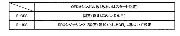
図13は、共通探索領域と端末固有探索領域のOFDMシンボル数の設定方法の一例を示す図である。基地局101は、E−CSSのOFDMシンボル数(あるいはスタート位置)を特定するCFI1を示す情報を、PBCHあるいはePCFICH(enhanced PCFICH)で報知する。端末102は、PBCHあるいはePCFICHで報知された信号で示されるCFI1から、E−CSSのOFDMシンボル数(あるいはスタート位置)を特定する。ここで、ePCFICHはPCFICHと同様CFIを報知するための物理チャネルであるが、PCFICHとは異なり、所定の限定された帯域内にマッピングされている物理チャネルである。例えば、PBCHと同様、中心の6PRBにマッピングされるようにしてもよいし、他の所定のPRBであってもよい。一方、基地局101は、E−USSのOFDMシンボル数(あるいはスタート位置)を特定するCFI2を示す情報を、専用RRCシグナリングで通知(設定)する。端末102は、通知(設定)されたCFI2から、E−USSのOFDMシンボル数(あるいはスタート位置)を特定する。
FIG. 13 is a diagram illustrating an example of a method for setting the number of OFDM symbols in the common search region and the terminal-specific search region. The
あるいは、E−CSSとE−USSとで、パンクチャリングを変えるようにしてもよい。図14は、共通探索領域と端末固有探索領域のパンクチャリングされるOFDMシンボル数の設定方法の一例を示す図である。基地局101は、E−CSS、E−USSともに、先頭のOFDMシンボルからマッピングする。基地局101は、E−CSSにおいてパンクチャリングされるOFDMシンボル数(あるいはエンド位置)を特定するCFI1を示す情報を、PBCHあるいはePCFICH(enhanced PCFICH)で報知する。端末102は、PBCHあるいはePCFICHで報知された信号で示されるCFI1から、E−CSSにおいてパンクチャリングされるOFDMシンボル数(あるいはエンド位置)を特定する。一方、基地局101は、E−USSにおいてパンクチャリングされるOFDMシンボル数(あるいはエンド位置)を特定するCFI2を示す情報を、専用RRCシグナリングで通知(設定)する。端末102は、通知(設定)されたCFI2から、E−USSにおいてパンクチャリングされるOFDMシンボル数(あるいはエンド位置)を特定する。
Alternatively, puncturing may be changed between E-CSS and E-USS. FIG. 14 is a diagram illustrating an example of a method for setting the number of OFDM symbols to be punctured between the common search region and the terminal-specific search region. The
このように、基地局101は、E−CSSとE−USSとで、E−PDCCHを実質的にマッピングする(あるいは実質的にマッピングしない)OFDMシンボル数を個別に設定する。また、基地局101は、E−CSSにおいてE−PDCCHを実質的にマッピングする(あるいは実質的にマッピングしない)OFDMシンボル数を特定する情報を報知し、E−USSにおいてE−PDCCHを実質的にマッピングする(あるいは実質的にマッピングしない)OFDMシンボル数を特定する情報を端末102に専用RRCシグナリングで通知する。端末102は、E−CSSにおいてE−PDCCHを実質的にマッピングする(あるいは実質的にマッピングしない)OFDMシンボル数を特定する情報に基づいてE−CSSを設定し、E−CSSにおいてE−PDCCHをモニタリングする。また、端末102は、E−USSにおいてE−PDCCHを実質的にマッピングする(あるいは実質的にマッピングしない)OFDMシンボル数を特定する情報に基づいてE−USSを設定し、E−USSにおいてE−PDCCHをモニタリングする。
As described above, the
これにより、探索領域の位置を基地局101と端末102との間で共通に設定することができる。また、E−CSSとE−USSとを個別に設定することができるため、効率的なE−PDCCHの送受信を行うことができる。特に、基地局101が、端末102とPDCCHを用いる端末106とで同時に通信する際、E−CSSおよびE−USSと、PDCCH領域が重複しないように設定することができるため、E−PDCCHとPDCCHが互いに干渉を与えない。また、端末102は、システム帯域内に広く分散配置されたPCFICHを取得しなくても、PDCCH領域と重複しないE−CSSを用いることができるため、PCFICHを取得する端末と比較して受信帯域を狭く設定することができる。さらに、端末102は、基地局101と専用シグナリングを行わなくても、PDCCH領域と重複しないE−CSSを用いることができるため、初期アクセスなど、コネクションが確立していない場合でもE−PDCCHの送受信が可能となる。また、ページングやシステム情報に関するDLグラントが配置されるE−CSSに対するOFDMシンボル数を特定する情報を報知することにより、複数の端末に対して共通に、かつ効率的に設定することができる。同時に、端末102は、PDCCH領域と重複しないようにE−CSSを安全なOFDMシンボル上に静的に設定し、E−USSの設定はPDCCH領域に応じて適応的に変更することができるため、効率的な制御チャネルの利用を行うことができる。
Thereby, the position of the search area can be set in common between the
(第2の実施形態)
第1の実施形態では、基地局から端末にCFI1を報知し、CFI2を通知する構成について説明した。これに対して、第2の実施形態では、CFI1は固定であり、基地局から端末にCFI2を通知する構成について説明する。以下、本発明の第2の実施形態について説明する。なお、本実施形態に係る基地局装置および端末装置は、図4および図5に示した基地局101および端末102の構成例と同様の構成で実現することができる。また、図2、図3および図6から図11に示したフレームおよびチャネル構成例と同様の構成で実現することができる。そのため、重複する部分について詳細な説明は繰返さない。
(Second Embodiment)
In the first embodiment, the configuration in which the base station broadcasts CFI 1 to the terminal and notifies CFI 2 has been described. On the other hand, in the second embodiment, a configuration in which CFI 1 is fixed and CFI 2 is notified from the base station to the terminal will be described. Hereinafter, a second embodiment of the present invention will be described. Note that the base station apparatus and the terminal apparatus according to the present embodiment can be realized with the same configuration as the configuration example of the
図15は、基地局101と端末102との間の下りリンクデータ送受信の流れを示す図である。CFI1は予め決められたパラメータであり、基地局101と端末102とで共通のパラメータとして予め設定されている。端末102は、予め決められたCFI1により特定されるOFDMシンボル数に基づいて、E−CSSを設定する(ステップS1501)。端末102は、E−CSSを設定すると、設定されたE−CSSにおいて、報知される送信データ(ページングやシステム情報やランダムアクセスレスポンスなど)を指定するE−PDCCH(ページング指示、SI指示、RAレスポンス指示など)、端末102宛の通常の送信データを指定するE−PDCCH(通常のDLグラント)、および、端末102からのデータ送信を指示するE−PDCCH(ULグラント)などをモニタリングする。基地局101は、報知される送信データ(ページングやシステム情報やランダムアクセスレスポンスなど)の送信、端末102宛の通常の送信データあるいは端末102からのデータ送信などが必要になった場合、E−CSSにおいて、E−PDCCHを送信する(ステップS1502)。また、E−PDCCHが下りリンクグラントである場合は、下りリンクの送信データを同じサブフレームで送信する。
FIG. 15 is a diagram illustrating a flow of downlink data transmission / reception between the
次に、基地局101は、端末102にCFI2をシグナリングする(ステップS1503)。好ましくは、専用RRCシグナリングなどの各端末102宛の個別のシグナリングを用いる。なお、ここでは、端末102がE−CSSをモニタリングしているときに、CFI2をシグナリングする場合を図示しているが、これに限るものではない。例えば、E−PDCCHではなく、PDCCHのみをモニタリングしているときでも、CFI2をシグナリングすることができる。端末102は、シグナリングされたCFI2により特定されるOFDMシンボル数に基づいて、E−USSを設定する(ステップS1504)。端末102は、U−CSSを設定すると、設定されたU−CSSにおいて、端末102宛の通常の送信データを指定するE−PDCCH(通常のDLグラント)、および端末102からのデータ送信を指示するE−PDCCH(ULグラント)などをモニタリングする。
基地局101は、端末102宛の通常の送信データあるいは端末102からのデータ送信などが必要になった場合、E−CSSまたはE−USSにおいて、E−PDCCHを送信する(ステップS1505)。また、E−PDCCHが下りリンクグラントである場合は、下りリンクの送信データを同じサブフレームで送信する。
Next, the
The
図16は、共通探索領域と端末固有探索領域のOFDMシンボル数の設定方法の一例を示す図である。E−CSSのOFDMシンボル数(あるいはスタート位置)を特定するCFI1を示す情報は固定パラメータであり、基地局101と端末102とで共通に設定されている。基地局101は、CFI1に基づくE−CSSにE−PDCCHを配置し、端末102は、CFI1に基づくE−CSSでE−PDCCHをモニタリングする。一方、基地局101は、E−USSのOFDMシンボル数(あるいはスタート位置)を特定するCFI2を示す情報を、専用RRCシグナリングで通知(設定)する。端末102は、通知(設定)されたCFI2から、E−USSのOFDMシンボル数(あるいはスタート位置)を特定する。
FIG. 16 is a diagram illustrating an example of a method for setting the number of OFDM symbols in the common search region and the terminal-specific search region. Information indicating CFI 1 that specifies the number of OFDM symbols (or start position) of E-CSS is a fixed parameter, and is commonly set in the
なお、図16の例では、E−CSSおよびE−USSのためのOFDMシンボル数を設定する場合について示しているが、第1の実施形態における図14の例と同様、E−CSSとE−USSとで、パンクチャリングするOFDMシンボル数を設定ようにしてもよい。また、図16では、E−CSSのスタート位置として第3シンボル目と固定する場合について示しているが、第3シンボル目に限定するものではない。例えば、E−CSSは先頭シンボルからマッピングするようにし、パンクチャリングを行わない(すなわちスタート位置を第1シンボル目に固定する)ようにすることもできる。 In the example of FIG. 16, the case of setting the number of OFDM symbols for E-CSS and E-USS is shown. However, as in the example of FIG. 14 in the first embodiment, E-CSS and E-CSS are set. The number of OFDM symbols to be punctured may be set with USS. FIG. 16 shows a case where the start position of the E-CSS is fixed to the third symbol, but is not limited to the third symbol. For example, the E-CSS can be mapped from the first symbol and puncturing is not performed (that is, the start position is fixed to the first symbol).
このように、基地局101は、E−CSSとE−USSとで、E−PDCCHを実質的にマッピングする(あるいは実質的にマッピングしない)OFDMシンボル数を個別に設定する。また、E−CSSにおいてE−PDCCHを実質的にマッピングする(あるいは実質的にマッピングしない)OFDMシンボル数を固定とし、基地局101は、E−USSにおいてE−PDCCHを実質的にマッピングする(あるいは実質的にマッピングしない)OFDMシンボル数(可変)を特定する情報を端末102に専用RRCシグナリングで通知する。端末102は、E−CSSにおいてE−PDCCHを実質的にマッピングする固定の(あるいは実質的にマッピングしない)OFDMシンボル数に基づいてE−CSSを設定し、E−CSSにおいてE−PDCCHをモニタリングする。また、端末102は、E−USSにおいてE−PDCCHを実質的にマッピングする(あるいは実質的にマッピングしない)OFDMシンボル数を特定する情報に基づいてE−USSを設定し、E−USSにおいてE−PDCCHをモニタリングする。
As described above, the
これにより、探索領域の位置を基地局101と端末102との間で共通に設定することができる。また、E−CSSとE−USSとを個別に設定することができるため、効率的なE−PDCCHの送受信を行うことができる。特に、基地局101が、端末102とPDCCHを用いる端末106とで同時に通信する際、E−CSSおよびE−USSとPDCCH領域との重複を制御できる。端末102は、システム帯域内に広く分散配置されたPCFICHを取得しなくても、PDCCH領域と重複しないE−CSSを用いることができるため、PCFICHを取得する端末と比較して受信帯域を狭く設定することができる。さらに、端末102は、基地局101と専用シグナリングを行わなくても、PDCCH領域と重複しないE−CSSを用いることができるため、初期アクセスなど、コネクションが確立していない場合でもE−PDCCHの送受信が可能となる。また、ページングやシステム情報に関するDLグラントが配置されるE−CSSに対するOFDMシンボル数を特定する情報を報知することにより、複数の端末に対して共通に、かつ効率的に設定することができる。同時に、端末102は、PDCCH領域と重複しないようにE−CSSを安全なOFDMシンボル上に静的に設定し、E−USSの設定はPDCCH領域に応じて適応的に変更することができるため、効率的な制御チャネルの利用を行うことができる。
Thereby, the position of the search area can be set in common between the
E−CSSの領域を、PDCCHと重複しないように固定する場合、E−CSSとPDCCHが干渉しないようにすることができる。また、E−CSSの領域を、PDCCHと重複を許すように固定(例えば、先頭シンボルからマッピングし、パンクチャリングを行わない)する場合、PDCCHの領域を知ることができる端末と、PDCCHの領域を知ることができない端末とで共通のマッピングを行うことができる。そのため、PDCCHの領域を知ることができる端末と、PDCCHの領域を知ることができない端末とで、E−CSSにおけるE−PDCCHを共用することができる。一方、端末固有のE−PDCCHのみが割り当てられるE−USSは、PDCCHの領域を知ることができる/できないによらず、端末固有にOFDMシンボル数を設定することができるため、PDCCHと干渉を起こさず、かつPDCCH領域が少ない場合でもE−PDCCH領域を拡大することで効率的なリソースの利用を行うことができる。 When the E-CSS area is fixed so as not to overlap with the PDCCH, the E-CSS and the PDCCH can be prevented from interfering with each other. In addition, when the E-CSS area is fixed so as to allow overlapping with the PDCCH (for example, mapping from the first symbol and puncturing is not performed), a terminal capable of knowing the PDCCH area and the PDCCH area A common mapping can be performed with terminals that cannot be known. Therefore, the terminal that can know the PDCCH region and the terminal that cannot know the PDCCH region can share the E-PDCCH in E-CSS. On the other hand, the E-USS to which only the terminal-specific E-PDCCH is allocated can set the number of OFDM symbols specific to the terminal regardless of whether or not the area of the PDCCH can be known, thus causing interference with the PDCCH. In addition, even when the PDCCH region is small, it is possible to efficiently use resources by expanding the E-PDCCH region.
(第3の実施形態)
第1の実施形態では、基地局から端末にCFI1を報知し、CFI2を通知する構成について説明した。これに対して、第3の実施形態では、CFI1を基地局から端末にを報知し(あるいはCFI1を固定とし)、基地局から端末にCFI2をCFI1とは異なるチャネルで報知する構成について説明する。以下、本発明の第3の実施形態について説明する。なお、本実施形態に係る基地局装置および端末装置は、図4および図5に示した基地局101および端末102の構成例と同様の構成で実現することができる。また、図2、図3および図6から図11に示したフレームおよびチャネル構成例と同様の構成で実現することができる。そのため、重複する部分について詳細な説明は繰返さない。
(Third embodiment)
In the first embodiment, the configuration in which the base station broadcasts CFI 1 to the terminal and notifies CFI 2 has been described. On the other hand, in the third embodiment, CFI 1 is broadcast from the base station to the terminal (or CFI 1 is fixed), and CFI 2 is broadcast from the base station to the terminal through a channel different from CFI 1. Will be described. Hereinafter, a third embodiment of the present invention will be described. Note that the base station apparatus and the terminal apparatus according to the present embodiment can be realized with the same configuration as the configuration example of the
図17は、基地局101と端末102との間の下りリンクデータ送受信の流れを示す図である。基地局101は、CFI1をPBCHで報知する(ステップS1701)。なお、CFI1が予め決められたパラメータであり、基地局101と端末102とで共通のパラメータとして予め設定される場合は、ステップS1701は不要である。基地局101は、CFI2をPCFICHあるいはえPCFICHで報知する(ステップS1702)。端末102は、CFI1により特定されるOFDMシンボル数に基づいて、E−CSSを設定する(ステップS1703)。端末102は、E−CSSを設定すると、設定されたE−CSSにおいて、報知される送信データ(ページングやシステム情報やランダムアクセスレスポンスなど)を指定するE−PDCCH(ページング指示、SI指示、RAレスポンス指示など)、端末102宛の通常の送信データを指定するE−PDCCH(通常のDLグラント)、および、端末102からのデータ送信を指示するE−PDCCH(ULグラント)などをモニタリングする。基地局101は、報知される送信データ(ページングやシステム情報やランダムアクセスレスポンスなど)の送信、端末102宛の通常の送信データあるいは端末102からのデータ送信などが必要になった場合、E−CSSにおいて、E−PDCCHを送信する(ステップS1704)。また、E−PDCCHが下りリンクグラントである場合は、下りリンクの送信データを同じサブフレームで送信する。なお、ここでは、端末102がE−CSSを設定する前に、基地局101がCFI2を報知する場合を図示しているが、これに限るものではない。例えば、PCFICHやePCFICHはサブフレーム毎に挿入することができるため、基地局101がサブフレーム毎にCFI2をで報知するようにしてもよい。
FIG. 17 is a diagram illustrating a flow of downlink data transmission / reception between the
端末102は、シグナリングされたCFI2により特定されるOFDMシンボル数に基づいて、E−USSを設定する(ステップS1504)。端末102は、U−CSSを設定すると、設定されたU−CSSにおいて、端末102宛の通常の送信データを指定するE−PDCCH(通常のDLグラント)、および端末102からのデータ送信を指示するE−PDCCH(ULグラント)などをモニタリングする。基地局101は、端末102宛の通常の送信データあるいは端末102からのデータ送信などが必要になった場合、E−CSSまたはE−USSにおいて、E−PDCCHを送信する(ステップS1505)。また、E−PDCCHが下りリンクグラントである場合は、下りリンクの送信データを同じサブフレームで送信する。
The terminal 102 sets E-USS based on the number of OFDM symbols specified by the signaled CFI 2 (step S1504). When the terminal 102 sets U-CSS, in the set U-CSS, the terminal 102 instructs E-PDCCH (normal DL grant) for specifying normal transmission data addressed to the terminal 102 and data transmission from the terminal 102. E-PDCCH (UL grant) is monitored. The
図18は、共通探索領域と端末固有探索領域のOFDMシンボル数の設定方法の一例を示す図である。基地局101は、E−CSSのOFDMシンボル数(あるいはスタート位置)を特定するCFI1を示す情報を、PBCHで報知する。あるいはE−CSSのOFDMシンボル数(あるいはスタート位置)を特定するCFI1を示す情報は固定パラメータであり、基地局101と端末102とで共通に設定されている。基地局101は、CFI1に基づくE−CSSにE−PDCCHを配置し、端末102は、CFI1に基づくE−CSSでE−PDCCHをモニタリングする。一方、基地局101は、E−USSのOFDMシンボル数(あるいはスタート位置)を特定するCFI2を示す情報を、PCFICHあるいはePCFICHで報知する。端末102は、報知されたCFI2から、E−USSのOFDMシンボル数(あるいはスタート位置)を特定する。
FIG. 18 is a diagram illustrating an example of a method for setting the number of OFDM symbols in the common search region and the terminal-specific search region. The
なお、図18の例では、E−CSSおよびE−USSのためのOFDMシンボル数を設定する場合について示しているが、第1の実施形態における図14の例と同様、E−CSSとE−USSとで、パンクチャリングするOFDMシンボル数を設定ようにしてもよい。 In the example of FIG. 18, the case of setting the number of OFDM symbols for E-CSS and E-USS is shown. However, as in the example of FIG. 14 in the first embodiment, E-CSS and E-US The number of OFDM symbols to be punctured may be set with USS.
このように、基地局101は、E−CSSとE−USSとで、E−PDCCHを実質的にマッピングする(あるいは実質的にマッピングしない)OFDMシンボル数を個別に設定する。また、E−CSSにおいてE−PDCCHを実質的にマッピングする(あるいは実質的にマッピングしない)OFDMシンボル数を固定(PBCHで報知されるパラメータもほぼ固定(静的)とみなすことができる)とし、基地局101は、E−USSにおいてE−PDCCHを実質的にマッピングする(あるいは実質的にマッピングしない)OFDMシンボル数を特定する情報を端末102にPCFICHやePCFICHなどの動的に報知内容を変更することができる報知チャネルで通知する。端末102は、E−CSSにおいてE−PDCCHを実質的にマッピングする固定の(あるいは実質的にマッピングしない)OFDMシンボル数に基づいてE−CSSを設定し、E−CSSにおいてE−PDCCHをモニタリングする。また、端末102は、E−USSにおいてE−PDCCHを実質的にマッピングする(あるいは実質的にマッピングしない)OFDMシンボル数を特定する情報に基づいてE−USSを設定し、E−USSにおいてE−PDCCHをモニタリングする。
As described above, the
これにより、探索領域の位置を基地局101と端末102との間で共通に設定することができる。また、E−CSSとE−USSとを個別に設定することができるため、効率的なE−PDCCHの送受信を行うことができる。特に、基地局101が、端末102とPDCCHを用いる端末106とで同時に通信する際、E−CSSおよびE−USSとPDCCH領域との重複を制御できる。端末102は、システム帯域内に広く分散配置されたPCFICHを取得しなくても、PDCCH領域と重複しないE−CSSを用いることができるため、PCFICHを取得する端末と比較して受信帯域を狭く設定することができる。さらに、端末102は、基地局101と専用シグナリングを行わなくても、PDCCH領域と重複しないE−CSSを用いることができるため、初期アクセスなど、コネクションが確立していない場合でもE−PDCCHの送受信が可能となる。また、ページングやシステム情報に関するDLグラントが配置されるE−CSSに対するOFDMシンボル数を特定する情報を報知することにより、複数の端末に対して共通に、かつ効率的に設定することができる。同時に、端末102は、PDCCH領域と重複しないようにE−CSSを安全なOFDMシンボル上に静的に設定し、E−USSの設定はPDCCH領域に応じて適応的に変更することができるため、効率的な制御チャネルの利用を行うことができる。
Thereby, the position of the search area can be set in common between the
E−CSSの領域を、PDCCHと重複しないように固定する場合、E−CSSとPDCCHが干渉しないようにすることができる。また、E−CSSの領域を、PDCCHと重複を許すように固定(例えば、先頭シンボルからマッピングし、パンクチャリングを行わない)する場合、PDCCHの領域を知ることができる端末と、PDCCHの領域を知ることができない端末とで共通のマッピングを行うことができる。そのため、PDCCHの領域を知ることができる端末と、PDCCHの領域を知ることができない端末とで、E−CSSにおけるE−PDCCHを共用することができる。一方、端末固有のE−PDCCHのみが割り当てられるE−USSは、PDCCHの領域に応じて、端末共通にOFDMシンボル数を設定することができるため、PDCCHと干渉を起こさず、かつPDCCH領域が少ない場合でもE−PDCCH領域を拡大することで効率的なリソースの利用を行うことができる。 When the E-CSS area is fixed so as not to overlap with the PDCCH, the E-CSS and the PDCCH can be prevented from interfering with each other. In addition, when the E-CSS area is fixed so as to allow overlapping with the PDCCH (for example, mapping from the first symbol and puncturing is not performed), a terminal capable of knowing the PDCCH area and the PDCCH area A common mapping can be performed with terminals that cannot be known. Therefore, the terminal that can know the PDCCH region and the terminal that cannot know the PDCCH region can share the E-PDCCH in E-CSS. On the other hand, the E-USS to which only the terminal-specific E-PDCCH is allocated can set the number of OFDM symbols in common to the terminals according to the PDCCH area, and thus does not cause interference with the PDCCH and has a small PDCCH area. Even in this case, it is possible to efficiently use resources by expanding the E-PDCCH region.
(第4の実施形態)
第1から第3の実施形態では、1つの基地局と端末との間のCFI1およびCFI2の設定について説明した。これに対して、第4の実施形態では、基地局間でのハンドオーバ(HO:Hand Over)時のCFI1およびCFI2の設定について説明する。以下、本発明の第4の実施形態について説明する。なお、本実施形態に係る基地局装置(ソース基地局およびターゲット基地局)および端末装置は、図4および図5に示した基地局101および端末102の構成例と同様の構成で実現することができる。また、図2、図3および図6から図11に示したフレームおよびチャネル構成例と同様の構成で実現することができる。そのため、重複する部分について詳細な説明は繰返さない。
(Fourth embodiment)
In the first to third embodiments, the setting of CFI 1 and CFI 2 between one base station and a terminal has been described. On the other hand, in the fourth embodiment, setting of CFI 1 and CFI 2 at the time of handover (HO: Hand Over) between base stations will be described. The fourth embodiment of the present invention will be described below. Note that the base station apparatus (source base station and target base station) and the terminal apparatus according to the present embodiment can be realized with the same configuration as the configuration example of the
図19は、HO元の基地局であるソース基地局、HO先の基地局であるターゲット基地局と端末102との間の下りリンクデータ送受信の流れを示す図である。ソース基地局からターゲット基地局へのHOが決定すると、ソース基地局は、ターゲット基地局のシステム情報、端末の新しいID、ランダムアクセスリソースなどの情報を、HOメッセージとして専用RRCシグナリングを用いて端末102に通知する。このとき、HOメッセージには、CFI1および/またはCFI2を特定する情報が含まれる(ステップS1901)。端末102は、ターゲット基地局と同期を取った後、ランダムアクセス手続きを開始する(ステップS1902)。端末102は、CFI1により特定されるOFDMシンボル数に基づいて、E−CSSを設定する(ステップS1903)。端末102は、E−CSSを設定すると、設定されたE−CSSにおいて、ランダムアクセスレスポンスや端末102からターゲット基地局へのデータ送信を指示するE−PDCCH(ULグラント)などをモニタリングする。ターゲット基地局101は、E−CSSにおいて、ランダムアクセスレスポンスを送信する(ステップS1904)。また、ターゲット基地局101は、E−CSSにおいて、E−PDCCH(ULグラント)を送信する(ステップS1905)。端末102は、RRC再設定の完了を示す通知を行う(ステップS1906)。
FIG. 19 is a diagram illustrating a flow of downlink data transmission / reception between the source base station that is the HO source base station, the target base station that is the HO destination base station, and the terminal 102. When the HO from the source base station to the target base station is determined, the source base station uses the dedicated RRC signaling as information about the target base station system information, the new ID of the terminal, random access resources, etc. as a HO message. Notify At this time, the HO message includes information for specifying CFI 1 and / or CFI 2 (step S1901). After synchronizing with the target base station, the terminal 102 starts a random access procedure (step S1902). The terminal 102 sets E-CSS based on the number of OFDM symbols specified by CFI 1 (step S1903). When the E-CSS is set, the terminal 102 monitors a random access response, an E-PDCCH (UL grant) instructing data transmission from the terminal 102 to the target base station, and the like in the set E-CSS. The
端末102は、シグナリングされたCFI2により特定されるOFDMシンボル数に基づいて、E−USSを設定する(ステップS1907)。端末102は、U−CSSを設定すると、設定されたU−CSSにおいて、端末102宛の通常の送信データを指定するE−PDCCH(通常のDLグラント)、および端末102からのデータ送信を指示するE−PDCCH(ULグラント)などをモニタリングする。基地局101は、端末102宛の通常の送信データあるいは端末102からのデータ送信などが必要になった場合、E−CSSまたはE−USSにおいて、E−PDCCHを送信する(ステップS1908)。また、E−PDCCHが下りリンクグラントである場合は、下りリンクの送信データを同じサブフレームで送信する。
The terminal 102 sets E-USS based on the number of OFDM symbols specified by the signaled CFI 2 (step S1907). When the terminal 102 sets U-CSS, in the set U-CSS, the terminal 102 instructs E-PDCCH (normal DL grant) for specifying normal transmission data addressed to the terminal 102 and data transmission from the terminal 102. E-PDCCH (UL grant) is monitored. The
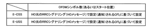
図20は、共通探索領域と端末固有探索領域のOFDMシンボル数の設定方法の一例を示す図である。ソース基地局は、E−CSSのOFDMシンボル数(あるいはスタート位置)を特定するCFI1を示す情報と、E−CSSのOFDMシンボル数(あるいはスタート位置)を特定するCFI1を示す情報とをHOメッセージに含めて端末102に通知する。ターゲット基地局は、CFI1に基づくE−CSSにE−PDCCHを配置し、端末102は、CFI1に基づくE−CSSでE−PDCCHをモニタリングする。一方、ターゲット基地局は、CFI2に基づくE−USSにE−PDCCHを配置し、端末102は、CFI2に基づくE−USSでE−PDCCHをモニタリングする。 FIG. 20 is a diagram illustrating an example of a method for setting the number of OFDM symbols in the common search region and the terminal-specific search region. The source base station, information indicating the CFI 1 for identifying E-CSS number of OFDM symbols (or start position), E-CSS number of OFDM symbols and information representing a CFI 1 to identify the (or start position) HO It is included in the message and notified to the terminal 102. Target base station, place the E-PDCCH in E-CSS based on CFI 1, terminal 102 monitors the E-PDCCH in E-CSS based on CFI 1. On the other hand, the target base station arranges the E-PDCCH in the E-USS based on CFI 2 , and the terminal 102 monitors the E-PDCCH in the E-USS based on CFI 2 .
なお、図20の例では、E−CSSおよびE−USSのためのOFDMシンボル数を設定する場合について示しているが、第1の実施形態における図14の例と同様、E−CSSとE−USSとで、パンクチャリングするOFDMシンボル数を設定ようにしてもよい。 Note that, in the example of FIG. 20, the case of setting the number of OFDM symbols for E-CSS and E-USS is shown, but as in the example of FIG. 14 in the first embodiment, E-CSS and E-US The number of OFDM symbols to be punctured may be set with USS.
このように、ソース基地局は、ターゲット基地局がE−CSSとE−USSとでE−PDCCHを実質的にマッピングする(あるいは実質的にマッピングしない)OFDMシンボル数を、個別に設定する。また、端末102は、E−CSSおよびE−USSのそれぞれにおいてE−PDCCHを実質的にマッピングする(あるいは実質的にマッピングしない)OFDMシンボル数を特定する情報に基づいてE−CSSおよびE−USSを設定し、E−CSSおよびE−USSにおいてE−PDCCHをモニタリングする。 Thus, the source base station individually sets the number of OFDM symbols in which the target base station substantially maps (or does not substantially map) E-PDCCH between E-CSS and E-USS. Also, the terminal 102 can determine whether the E-CSS and E-USS are based on information specifying the number of OFDM symbols that substantially map (or do not map) E-PDCCH in each of E-CSS and E-USS. To monitor E-PDCCH in E-CSS and E-USS.
これにより、探索領域の位置をターゲット基地局と端末102との間で共通に設定することができる。また、E−CSSとE−USSとを個別に設定することができるため、効率的なE−PDCCHの送受信を行うことができる。 Thereby, the position of the search area can be set in common between the target base station and the terminal 102. Moreover, since E-CSS and E-USS can be set separately, efficient transmission and reception of E-PDCCH can be performed.
なお、上記各実施形態では、端末がPDCCHあるいはE−PDCCHをCSSで検出するか、USSで検出するかに応じて、E−PDCCHが実質的にマッピングされるOFDMシンボル数を切り替えた。しかしながら、SSに代えて、DCIフォーマットに応じて切り替えるようにしても、上記各実施形態に近い効果を得ることができる。より具体的には、端末がPDCCHあるいはE−PDCCHとして、CSSで送信可能なDCIフォーマットを検出するか、USSでのみ送信可能なDCIフォーマットを検出するかに応じて、E−PDCCHが実質的にマッピングされるOFDMシンボル数を切り替える。また、基地局がPDCCHあるいはE−PDCCHとしてCSSで送信可能なDCIフォーマットを送信するか、USSでのみ送信可能なDCIフォーマットを送信するかに応じて、E−PDCCHを実質的にマッピングするOFDMシンボル数を切り替える。 In each of the above embodiments, the number of OFDM symbols to which the E-PDCCH is substantially mapped is switched according to whether the terminal detects PDCCH or E-PDCCH by CSS or USS. However, even if the switching is performed in accordance with the DCI format instead of the SS, an effect close to that of each of the above embodiments can be obtained. More specifically, depending on whether a terminal detects a DCI format that can be transmitted by CSS or a DCI format that can be transmitted only by USS as PDCCH or E-PDCCH, E-PDCCH is substantially Switches the number of mapped OFDM symbols. An OFDM symbol that substantially maps the E-PDCCH depending on whether the base station transmits a DCI format that can be transmitted by CSS as PDCCH or E-PDCCH or a DCI format that can be transmitted only by USS. Switch the number.
なお、上記各実施形態では、データチャネル、制御チャネル、PDSCH、PDCCHおよび参照信号のマッピング単位としてリソースエレメントやリソースブロックを用い、時間方向の送信単位としてサブフレームや無線フレームを用いて説明したが、これに限るものではない。任意の周波数と時間で構成される領域および時間単位をこれらに代えて用いても、同様の効果を得ることができる。 In each of the embodiments described above, resource elements and resource blocks are used as data channel, control channel, PDSCH, PDCCH and reference signal mapping units, and subframes and radio frames are used as time direction transmission units. This is not a limitation. The same effect can be obtained even if a region and a time unit composed of an arbitrary frequency and time are used instead.
また、上記各実施形態では、PDSCH領域に配置される拡張された物理下りリンク制御チャネルをE−PDCCHと呼称し、従来の物理下りリンク制御チャネル(PDCCH)との区別を明確にして説明したが、これに限るものではない。両方をPDCCHと称する場合であっても、主にPDSCH領域に配置される拡張された物理下りリンク制御チャネルとPDCCH領域に配置される従来の物理下りリンク制御チャネルとで異なる動作をすれば、E−PDCCHとPDCCHとを区別する上記各実施形態と実質的に同じである。 In each of the above embodiments, the extended physical downlink control channel arranged in the PDSCH region is referred to as E-PDCCH, and the distinction from the conventional physical downlink control channel (PDCCH) has been clarified. However, it is not limited to this. Even when both are referred to as PDCCH, if the extended physical downlink control channel mainly disposed in the PDSCH region and the conventional physical downlink control channel disposed in the PDCCH region perform different operations, E -It is substantially the same as each said embodiment which distinguishes PDCCH and PDCCH.
なお、端末が基地局と通信を開始する際に、基地局に対して上記各実施形態で記載の機能が使用可能であるか否かを示す情報(端末能力情報、あるいは機能グループ情報)を基地局に通知することにより、基地局は上記各実施形態で記載の機能が使用可能であるか否かを判断することができる。より具体的には、上記各実施形態で記載の機能が使用可能である場合に、端末能力情報にそれを示す情報を含め、上記各実施形態で記載の機能が使用可能ではない場合には、端末能力情報に本機能に関する情報を含めないようにすればよい。あるいは、上記各実施形態で記載の機能が使用可能である場合に、機能グループ情報の所定ビットフィールドに1を立て、上記各実施形態で記載の機能が使用可能ではない場合には、機能グループ情報の所定ビットフィールドを0とするようにすればよい。 When the terminal starts communication with the base station, information (terminal capability information or function group information) indicating whether the functions described in the above embodiments can be used for the base station By notifying the station, the base station can determine whether or not the functions described in the above embodiments can be used. More specifically, when the function described in each of the above embodiments can be used, information indicating it is included in the terminal capability information, and when the function described in each of the above embodiments is not usable, Information related to this function may not be included in the terminal capability information. Alternatively, when the function described in each of the above embodiments can be used, 1 is set in the predetermined bit field of the function group information, and when the function described in each of the above embodiments is not usable, the function group information The predetermined bit field may be set to 0.
本発明に関わる基地局および端末で動作するプログラムは、本発明に関わる上記実施形態の機能を実現するように、CPU等を制御するプログラム(コンピュータを機能させるプログラム)である。そして、これら装置で取り扱われる情報は、その処理時に一時的にRAMに蓄積され、その後、各種ROMやHDDに格納され、必要に応じてCPUによって読み出し、修正・書き込みが行なわれる。プログラムを格納する記録媒体としては、半導体媒体(例えば、ROM、不揮発性メモリカード等)、光記録媒体(例えば、DVD、MO、MD、CD、BD等)、磁気記録媒体(例えば、磁気テープ、フレキシブルディスク等)等のいずれであってもよい。また、ロードしたプログラムを実行することにより、上述した実施形態の機能が実現されるだけでなく、そのプログラムの指示に基づき、オペレーティングシステムあるいは他のアプリケーションプログラム等と共同して処理することにより、本発明の機能が実現される場合もある。 A program that operates in a base station and a terminal related to the present invention is a program that controls a CPU or the like (a program that causes a computer to function) so as to realize the functions of the above-described embodiments related to the present invention. Information handled by these devices is temporarily stored in the RAM at the time of processing, then stored in various ROMs and HDDs, read out by the CPU, and corrected and written as necessary. As a recording medium for storing the program, a semiconductor medium (for example, ROM, nonvolatile memory card, etc.), an optical recording medium (for example, DVD, MO, MD, CD, BD, etc.), a magnetic recording medium (for example, magnetic tape, Any of a flexible disk etc. may be sufficient. In addition, by executing the loaded program, not only the functions of the above-described embodiment are realized, but also based on the instructions of the program, the processing is performed in cooperation with the operating system or other application programs. The functions of the invention may be realized.
また市場に流通させる場合には、可搬型の記録媒体にプログラムを格納して流通させたり、インターネット等のネットワークを介して接続されたサーバコンピュータに転送したりすることができる。この場合、サーバコンピュータの記憶装置も本発明に含まれる。また、上述した実施形態における基地局および端末の一部、または全部を典型的には集積回路であるLSIとして実現してもよい。基地局および端末の各機能ブロックは個別にチップ化してもよいし、一部、または全部を集積してチップ化してもよい。また、集積回路化の手法はLSIに限らず専用回路、または汎用プロセッサで実現しても良い。また、半導体技術の進歩によりLSIに代替する集積回路化の技術が出現した場合、当該技術による集積回路を用いることも可能である。 In the case of distribution in the market, the program can be stored and distributed in a portable recording medium, or transferred to a server computer connected via a network such as the Internet. In this case, the storage device of the server computer is also included in the present invention. Further, part or all of the base station and the terminal in the above-described embodiment may be realized as an LSI that is typically an integrated circuit. Each functional block of the base station and the terminal may be individually chipped, or a part or all of them may be integrated into a chip. Further, the method of circuit integration is not limited to LSI, and may be realized by a dedicated circuit or a general-purpose processor. In addition, when an integrated circuit technology that replaces LSI appears due to progress in semiconductor technology, an integrated circuit based on the technology can also be used.
以上、この発明の実施形態に関して図面を参照して詳述してきたが、具体的な構成はこの実施形態に限られるものではなく、この発明の要旨を逸脱しない範囲の設計変更等も含まれる。また、本発明は、請求項に示した範囲で種々の変更が可能であり、異なる実施形態にそれぞれ開示された技術的手段を適宜組み合わせて得られる実施形態についても本発明の技術的範囲に含まれる。また、上記各実施形態に記載された要素であり、同様の効果を奏する要素同士を置換した構成も含まれる。 The embodiment of the present invention has been described in detail with reference to the drawings. However, the specific configuration is not limited to this embodiment, and includes design changes and the like without departing from the gist of the present invention. The present invention can be modified in various ways within the scope of the claims, and embodiments obtained by appropriately combining technical means disclosed in different embodiments are also included in the technical scope of the present invention. It is. Moreover, it is the element described in each said embodiment, and the structure which substituted the element which has the same effect is also contained.
本発明は、無線基地局装置や無線端末装置や無線通信システムや無線通信方法に用いて好適である。 The present invention is suitable for use in a radio base station apparatus, a radio terminal apparatus, a radio communication system, and a radio communication method.
101 基地局
102、106 端末
103 共通探索領域における拡張物理下りリンク制御チャネル
104 下りリンク送信データ
105 端末固有探索領域における拡張物理下りリンク制御チャネル
107 物理下りリンク制御チャネル
401 コードワード生成部
402 下りリンクサブフレーム生成部
403 物理下りリンク制御チャネル生成部
404 OFDM信号送信部
405、511 送信アンテナ
406、501 受信アンテナ
407 SC−FDMA信号受信部
408 上りリンクサブフレーム処理部
409、506 上位層
502 OFDM信号受信部
503 下りリンクサブフレーム処理部
504 物理下りリンク制御チャネル抽出部
505 コードワード抽出部
507 上りリンクサブフレーム生成部
508 SC−FDMA信号送信部
2101 基地局
2102 端末
2103 共通探索領域における物理下りリンク制御チャネル
2104 下りリンク送信データ
2105 端末固有探索領域における物理下りリンク制御チャネル
101
Claims (10)
第1の報知情報を伝送する第1の物理チャネルであって、6個のリソースブロックにより配置される第1の物理チャネルを受信し、
拡張物理下りリンク制御チャネル用共通探索領域内の拡張物理下りリンク制御チャネルをモニタし、
前記拡張物理下りリンク制御チャネルのOFDMシンボルの開始位置である第1の開始位置は、前記第1の報知情報により指示され、
前記拡張物理下りリンク制御チャネルは、ページングに関する拡張物理下りリンク制御チャネルである、
端末装置。 A terminal device that communicates with a base station device,
A first physical channel for transmitting the first broadcast information, the first physical channel arranged by six resource blocks;
Monitor the extended physical downlink control channel in the common search area for the extended physical downlink control channel,
The first start position that is the start position of the OFDM symbol of the extended physical downlink control channel is indicated by the first broadcast information,
The extended physical downlink control channel is an extended physical downlink control channel related to paging.
Terminal device.
第1の報知情報を伝送する第1の物理チャネルであって、6個のリソースブロックにより配置される第1の物理チャネルを送信し、
拡張物理下りリンク制御チャネル用共通探索領域内の拡張物理下りリンク制御チャネルを送信し、
前記拡張物理下りリンク制御チャネルのOFDMシンボルの開始位置である第1の開始位置を、前記第1の報知情報により指示され、
前記拡張物理下りリンク制御チャネルは、ページングに関する拡張物理下りリンク制御チャネルである、
基地局装置。 A base station device that communicates with a terminal device,
A first physical channel that transmits the first broadcast information, the first physical channel arranged by six resource blocks;
Transmit the extended physical downlink control channel in the common search area for the extended physical downlink control channel,
A first start position that is a start position of an OFDM symbol of the extended physical downlink control channel is indicated by the first broadcast information,
The extended physical downlink control channel is an extended physical downlink control channel related to paging.
Base station device.
第1の報知情報を伝送する第1の物理チャネルであって、6個のリソースブロックにより配置される第1の物理チャネルを受信する過程と、
拡張物理下りリンク制御チャネル用共通探索領域内の拡張物理下りリンク制御チャネルをモニタする過程と
を有し、
前記拡張物理下りリンク制御チャネルのOFDMシンボルの開始位置である第1の開始位置は、前記第1の報知情報により指示され、
前記拡張物理下りリンク制御チャネルは、ページングに関する拡張物理下りリンク制御チャネルである、
通信方法。 A communication method of a terminal device that communicates with a base station device,
Receiving a first physical channel for transmitting first broadcast information, which is a first physical channel arranged by six resource blocks;
Monitoring the extended physical downlink control channel in the common search area for the extended physical downlink control channel, and
The first start position that is the start position of the OFDM symbol of the extended physical downlink control channel is indicated by the first broadcast information,
The extended physical downlink control channel is an extended physical downlink control channel related to paging.
Communication method.
第1の報知情報を伝送する第1の物理チャネルであって、6個のリソースブロックにより配置される第1の物理チャネルを送信する過程と、
拡張物理下りリンク制御チャネル用共通探索領域内の拡張物理下りリンク制御チャネルを送信する過程と
を有し、
前記拡張物理下りリンク制御チャネルのOFDMシンボルの開始位置である第1の開始位置は、前記第1の報知情報により指示され、
前記拡張物理下りリンク制御チャネルは、ページングに関する拡張物理下りリンク制御チャネルである、
通信方法。 A communication method of a base station device that communicates with a terminal device,
Transmitting a first physical channel for transmitting first broadcast information, which is a first physical channel arranged by six resource blocks;
Transmitting an extended physical downlink control channel in the common search area for the extended physical downlink control channel, and
The first start position that is the start position of the OFDM symbol of the extended physical downlink control channel is indicated by the first broadcast information,
The extended physical downlink control channel is an extended physical downlink control channel related to paging.
Communication method.
第1の報知情報を伝送する第1の物理チャネルであって、6個のリソースブロックにより配置される第1の物理チャネルを受信する処理部を備え、
前記処理部は、拡張物理下りリンク制御チャネル用共通探索領域内の拡張物理下りリンク制御チャネルをモニタし、
前記拡張物理下りリンク制御チャネルのOFDMシンボルの開始位置である第1の開始位置は、前記第1の報知情報により指示され、
前記拡張物理下りリンク制御チャネルは、ページングに関する拡張物理下りリンク制御チャネルである、
集積回路。 An integrated circuit that can be mounted on a terminal device that communicates with a base station device,
A first physical channel for transmitting the first broadcast information, the processing unit receiving a first physical channel arranged by six resource blocks;
The processing unit monitors the extended physical downlink control channel in the common search area for the extended physical downlink control channel,
The first start position that is the start position of the OFDM symbol of the extended physical downlink control channel is indicated by the first broadcast information,
The extended physical downlink control channel is an extended physical downlink control channel related to paging.
Integrated circuit.
第1の報知情報を伝送する第1の物理チャネルであって、6個のリソースブロックにより配置される第1の物理チャネルを送信する処理部を備え、
前記処理部は、拡張物理下りリンク制御チャネル用共通探索領域内の拡張物理下りリンク制御チャネルを送信し、
前記拡張物理下りリンク制御チャネルのOFDMシンボルの開始位置である第1の開始位置は、前記第1の報知情報により指示され、
前記拡張物理下りリンク制御チャネルは、ページングに関する拡張物理下りリンク制御チャネルである、
集積回路。 An integrated circuit that can be mounted on a base station device that communicates with a terminal device,
A first physical channel for transmitting the first broadcast information, the processing unit transmitting a first physical channel arranged by six resource blocks;
The processing unit transmits an extended physical downlink control channel in the common search area for the extended physical downlink control channel,
The first start position that is the start position of the OFDM symbol of the extended physical downlink control channel is indicated by the first broadcast information,
The extended physical downlink control channel is an extended physical downlink control channel related to paging.
Integrated circuit.
Priority Applications (1)
| Application Number | Priority Date | Filing Date | Title |
|---|---|---|---|
| JP2017002897A JP2017063508A (en) | 2017-01-11 | 2017-01-11 | Terminal device, base station device, communication method, and integrated circuit |
Applications Claiming Priority (1)
| Application Number | Priority Date | Filing Date | Title |
|---|---|---|---|
| JP2017002897A JP2017063508A (en) | 2017-01-11 | 2017-01-11 | Terminal device, base station device, communication method, and integrated circuit |
Related Parent Applications (1)
| Application Number | Title | Priority Date | Filing Date |
|---|---|---|---|
| JP2012114488A Division JP2013243460A (en) | 2012-05-18 | 2012-05-18 | Terminal, base station, communication system, and communication method |
Publications (1)
| Publication Number | Publication Date |
|---|---|
| JP2017063508A true JP2017063508A (en) | 2017-03-30 |
Family
ID=58430308
Family Applications (1)
| Application Number | Title | Priority Date | Filing Date |
|---|---|---|---|
| JP2017002897A Pending JP2017063508A (en) | 2017-01-11 | 2017-01-11 | Terminal device, base station device, communication method, and integrated circuit |
Country Status (1)
| Country | Link |
|---|---|
| JP (1) | JP2017063508A (en) |
-
2017
- 2017-01-11 JP JP2017002897A patent/JP2017063508A/en active Pending
Non-Patent Citations (2)
| Title |
|---|
| FUJITSU: "Motivation, Requirements and Design for ePCFICH", 3GPP TSG RAN WG1 MEETING #69 R1-122074, JPN6018012760, 12 May 2012 (2012-05-12), pages 第4頁 * |
| LG ELECTRONICS: "Discussion on eREG/eCCE definition", 3GPP TSG RAN WG1 MEETING #69 R1-122308, JPN6018012762, 12 May 2012 (2012-05-12), pages 第2頁 * |
Similar Documents
| Publication | Publication Date | Title |
|---|---|---|
| WO2013172370A1 (en) | Terminal, base station, communication system and communication method | |
| US11937264B2 (en) | Method and apparatus for control channel reception in wireless communication systems | |
| EP2544482B1 (en) | Wireless communication system, base station apparatus, mobile station apparatus, wireless communication method and integrated circuit | |
| JP5811443B2 (en) | Terminal device, base station device, integrated circuit, and communication method | |
| JP2016529745A (en) | Terminal apparatus, base station apparatus, communication system, communication method, and integrated circuit | |
| JP2011182348A5 (en) | ||
| US20160007341A1 (en) | Terminal, base station, communication system, and communication method | |
| US9832001B2 (en) | Terminal device, base station, communication system, and communication method | |
| JP6255642B2 (en) | Mobile station apparatus, base station apparatus, and communication method | |
| CN107864030B (en) | Terminal device, base station device, and communication method | |
| US9398580B2 (en) | Terminal, base station, communications system, and communications method | |
| JP5981740B2 (en) | Terminal, base station, communication system and communication method | |
| JP2011166650A (en) | Base station device, mobile station device, communication system and communication method | |
| JP5711338B2 (en) | Base station apparatus, mobile station apparatus, communication method, and integrated circuit | |
| JP2017063508A (en) | Terminal device, base station device, communication method, and integrated circuit | |
| JP5417409B2 (en) | Wireless communication system, base station apparatus, mobile station apparatus, wireless communication method, and integrated circuit | |
| JP2013255137A (en) | Terminal, base station, communication system, and communication method |
Legal Events
| Date | Code | Title | Description |
|---|---|---|---|
| A621 | Written request for application examination |
Free format text: JAPANESE INTERMEDIATE CODE: A621 Effective date: 20170111 |
|
| A131 | Notification of reasons for refusal |
Free format text: JAPANESE INTERMEDIATE CODE: A131 Effective date: 20180410 |
|
| A521 | Request for written amendment filed |
Free format text: JAPANESE INTERMEDIATE CODE: A523 Effective date: 20180525 |
|
| A02 | Decision of refusal |
Free format text: JAPANESE INTERMEDIATE CODE: A02 Effective date: 20180703 |
|
| A521 | Request for written amendment filed |
Free format text: JAPANESE INTERMEDIATE CODE: A523 Effective date: 20181003 |
|
| A911 | Transfer to examiner for re-examination before appeal (zenchi) |
Free format text: JAPANESE INTERMEDIATE CODE: A911 Effective date: 20181015 |
|
| A912 | Re-examination (zenchi) completed and case transferred to appeal board |
Free format text: JAPANESE INTERMEDIATE CODE: A912 Effective date: 20181229 |
|
| A521 | Request for written amendment filed |
Free format text: JAPANESE INTERMEDIATE CODE: A523 Effective date: 20191115 |