JP2017050382A - Device mounting feeder - Google Patents
Device mounting feeder Download PDFInfo
- Publication number
- JP2017050382A JP2017050382A JP2015172054A JP2015172054A JP2017050382A JP 2017050382 A JP2017050382 A JP 2017050382A JP 2015172054 A JP2015172054 A JP 2015172054A JP 2015172054 A JP2015172054 A JP 2015172054A JP 2017050382 A JP2017050382 A JP 2017050382A
- Authority
- JP
- Japan
- Prior art keywords
- release film
- knife edge
- edge member
- device mounting
- roller
- Prior art date
- Legal status (The legal status is an assumption and is not a legal conclusion. Google has not performed a legal analysis and makes no representation as to the accuracy of the status listed.)
- Pending
Links
Images


Landscapes
- Folding Of Thin Sheet-Like Materials, Special Discharging Devices, And Others (AREA)
- Supply And Installment Of Electrical Components (AREA)
Abstract
Description
本発明は、例えば、フレキシブル基板やフレキシブル配線の製造や、それらを組み合わせた電子機器の製造工程で、補強や電磁波吸収の目的で用いられている裏面に粘着層を有するシート状、薄板状、または発泡体状のデバイスについて、それを高速にかつ安定して、個別に搬送、剥離するためのデバイス実装用フィーダーに関する。 The present invention is, for example, a flexible substrate or a flexible wiring, or a manufacturing process of an electronic device that combines them, in the form of a sheet, a thin plate, or an adhesive layer on the back surface used for the purpose of reinforcement or electromagnetic wave absorption, or The present invention relates to a device mounting feeder for individually conveying and peeling a foam-like device individually at high speed.
従来、特許文献1に開示されるように、フレキシブル基板やフレキシブル配線の製造や、それらを組み合わせた電子機器の製造工程で、補強や電磁波吸収の目的で用いられている裏面に粘着層を有するシート状、薄板状、または発泡体状のデバイスが用いられている。 Conventionally, as disclosed in Patent Document 1, a sheet having an adhesive layer on the back surface used for the purpose of reinforcement or electromagnetic wave absorption in the manufacturing process of a flexible substrate or flexible wiring, or the manufacturing process of an electronic device combining them , Thin plate or foam devices are used.
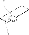
このようなデバイス100は、図10に示すように、フレキシブル基板102に貼り合わせて用いられる。
図11,12は、デバイス100とフレキシブル基板102とを貼着させる工程を説明するための概略構成図である。
Such a
11 and 12 are schematic configuration diagrams for explaining a process of attaching the
図11に示すように、デバイス100は、幅広い弱粘着シート104にあらかじめマトリックス状に仮付けし、弱粘着シート104は第1の型枠106に固定する。一方で、フレキシブル基板102も、幅広い弱粘着シート104にあらかじめマトリックス状に仮付けし、弱粘着シート104は第2の型枠108に固定する。
As shown in FIG. 11, the
なお、図11,12に示す構成では、第1の型枠106に位置決め穴110が設けられ、第2の型枠108にパイロットピン112が設けられており、パイロットピン112を位置決め穴110にはめ込むことで精度良くデバイス100とフレキシブル基板102とを貼着することができる。
11 and 12, the
このような方法では、一度に多数のデバイス100とフレキシブル基板102とを貼着することが可能であるが、弱粘着シート104に仮付けする際の位置決めが正確でないと、図13に示すように、全体的に偏ってしまう。また、仮付けの際にピッチ誤差があった場合には、図14に示すように、一部のデバイス100とフレキシブル基板102とが正確に貼着することができず、図15に示すような不具合品が多数発生することになる。
In such a method, it is possible to stick a large number of
しかしながら、デバイス100及びフレキシブル基板102のそれぞれの位置・姿勢を確認しながら貼着することは困難であるため、不具合品の発生は回避できず、仕損コストが重くなりがちであった。
However, since it is difficult to attach the
このため、本発明者らは、図16に示すように、幅広の弱粘着シート104の代わりに、長尺のテープ状剥離フィルム114に変え、剥離フィルム114にデバイス100を一列に仮付けし、例えば、電子部品実装機のテーピングパッケージによるデバイス搬送のように、個別に剥離、吸着パッドを持つロボットによるハンドリング、画像解析による位置・姿勢の認識と補正、ロボットによる貼着について検討を行った。
For this reason, as shown in FIG. 16, the present inventors changed to a long tape-
ここで、類似の形状を有するデバイスを剥離、移載、貼着を実行する既存の装置としては、例えば、下記(A)、(B)、(C)のような構成が知られている。 Here, as an existing apparatus that performs peeling, transfer, and sticking of devices having similar shapes, for example, the following configurations (A), (B), and (C) are known.
(A)図17,18に示すように、搬送ローラ120,122,124,126によって剥離フィルム114を所定方向に搬送し、ナイフエッジ部材128の陵辺128aによって剥離フィルム114からデバイス100を剥離するとともに、デバイス100を剥離後に強粘着しない素材や構造を有する仮載台116へ押し出し、仮載台116上に載置されたデバイス100を移載ヘッド118によって吸着、移載、貼着を行う。なお、符号130,132は、搬送ローラ120,124をそれぞれ駆動するためのモータである。
(A) As shown in FIGS. 17 and 18, the
しかしながら、このような装置は、デバイス100の素材自体にある程度の剛性(コシ)が無ければ実現できず、シート状、薄板状、または発泡体状のデバイス100については適用できない。
However, such an apparatus cannot be realized if the material itself of the
(B)図19,20に示すように、剥離フィルム114は、剥離フィルム114に所定のテンションを与えるためのテンションローラ134に巻装され、巻き取りローラ136によって剥離フィルム114を巻き取ることにより、ナイフエッジ部材128の陵辺128aによって剥離フィルム114からデバイス100を剥離後、直接、貼着相手であるフレキシブル基板102などに貼着する。なお、符号138は巻き取りローラ136を駆動するためのモータである。
(B) As shown in FIGS. 19 and 20, the
この方法では、剥離後、直接、貼着対象物に貼着するため、デバイス100の画像認識と位置・姿勢の補正が不可能である。また、剥離、貼着装置ごとロボットがハンドリングすることになるため、剥離・搬送装置はロボットに固定され、複数・多品種のデバイスを混載することは不可能である。
In this method, the image is recognized and the position / posture of the
(C)図21,22,23に示すように、単一の制御装置140により剥離フィルム114とデバイス100の搬送と、移載ヘッド118の移動とを制御し、搬送されるデバイス100の上面を移載ヘッド118が吸着しながら、ナイフエッジ部材128の陵辺128aでデバイス100の剥離を生じさせる。なお、符号142は、移載ヘッド118を動作させるためのモータである。
(C) As shown in FIGS. 21, 22, and 23, the
この方法では、剥離フィルム114の搬送と移載ヘッド118とを完全に同期させて動作させる必要があり、制御が複雑になってしまい、既存の装置の転用などは困難である。
In this method, it is necessary to operate the transfer of the
また、上記(C)の構成の装置においては、通常、剥離フィルム114を搬送ローラ120〜126の駆動により図24の矢印で示す方向に搬送すると、ナイフエッジ部材128の陵辺128aで剥離フィルム114が折り返され、剥離フィルム114上面に貼着されたデバイス100が剥離される。
In the apparatus having the above configuration (C), when the
しかしながら、デバイス100がシート状、薄板状、または発泡体状など、変形しやすい形状や素材で構成される場合には、素材の剛性(コシ)が十分ではなく、図25に示すように、ナイフエッジ部材128の陵辺128aを回り込んで剥離しない可能性がある。
However, when the
このため、連続して剥離フィルム114とデバイス100の粘着層との界面で剥離を生じさせるためには、図26に示すように、移載ヘッド118による吸引により、デバイス100の姿勢と形状を保持する必要がある。
For this reason, in order to continuously cause peeling at the interface between the
このとき、剥離フィルム114は搬送ローラ124,126の回転により搬送されているので、デバイス100もそれにつれて移動をしており、移載ヘッド118が吸着によりデバイス100の姿勢と形状を保持するためには、図23に示すように、デバイス100の移動、すなわち剥離フィルム114の搬送に同期して、移載ヘッド118自身も平行移動する必要が生じる。
At this time, since the
このようなフィルム搬送と移載ヘッド118の平行移動の完全な同期は、フィルム搬送と、移載ヘッド118の駆動制御を、例えば、図22に示すように、単一の制御装置140で行わなければ非常に困難である。例えば、従来の電子部品実装機における実装機本体と、それに搭載されるテープフィーダとの間で、テープの搬送を完全に同期して移載ヘッド118を移動させることはほとんど不可能である。
For such complete synchronization of the film transport and the parallel movement of the
図27に示すように、一般的に、フィーダに搭載された制御装置140と実装機の制御装置144とは、互いに通信146によって、それぞれの動作タイミングを合わせている。しかしながら、実行する動作の「開始」、「完了(インポジション)」、「実行中(ビジー)」などの実行タスク単位での通信であって、モータ制御上のステップ単位での位置の同期は行われていなかった。このため、高精度でフィルムの搬送位置と、移載ヘッドの位置とを合わせて同期駆動することは非常に困難である。
As shown in FIG. 27, generally, the
本発明では、このような現状に鑑み、ナイフエッジ部材を前後に駆動することによって、空間上に固定された移載ヘッドとデバイスに対して、剥離フィルムの折り返し位置を相対的に移動させることで、完全な同期でデバイスと移載ヘッドとを移動させる場合と同様な状態でデバイスの剥離を実現することができるデバイス実装用フィーダーを提供することを目的とする。 In the present invention, in view of such a current situation, by driving the knife edge member back and forth, the folding position of the release film is moved relative to the transfer head and the device fixed in the space. It is an object of the present invention to provide a device mounting feeder that can realize device peeling in the same state as when the device and the transfer head are moved in perfect synchronization.
本発明は、前述するような従来技術における課題を解決するために発明されたものであって、本発明のデバイス実装用フィーダーは、
長尺のテープ状剥離フィルムに所定のピッチで仮付けされたデバイスを、該剥離フィルムから剥離するためのデバイス実装用フィーダーであって、
前記剥離フィルムを第1の進行方向から第2の進行方向に折り返すことで、前記デバイスを前記剥離フィルムから剥離するナイフエッジ部材を備え、
前記ナイフエッジ部材は、前記第1の進行方向と平行に前後動可能に構成されていることを特徴とする。
The present invention was invented to solve the problems in the prior art as described above, and the device mounting feeder of the present invention is
A device mounted feeder for peeling a device temporarily attached to a long tape-like release film at a predetermined pitch from the release film,
A knife edge member for peeling the device from the release film by folding the release film from the first direction of travel to the second direction of travel;
The knife edge member is configured to be movable back and forth in parallel with the first traveling direction.
また、本発明では、前記ナイフエッジ部材と平行に同一ストロークで動作する可動ローラと、
前記可動ローラと略同一の接平面を有し、前記剥離フィルムの搬送経路を前記ナイフエッジ部材の可動方向と平行に案内する固定ローラと、
をさらに備えることが好ましい。
In the present invention, a movable roller that operates in the same stroke in parallel with the knife edge member;
A fixed roller that has substantially the same tangent plane as the movable roller and guides the transport path of the release film in parallel with the movable direction of the knife edge member;
It is preferable to further comprise.
また、本発明では、前記ナイフエッジ部材と、前記可動ローラとが支持体に設けられ、
前記支持体を前記第1の進行方向と平行に前後動可能に構成されていることが好ましい。
また、本発明では、前記デバイスの表面を吸着し、該デバイスの位置と姿勢を把持する移載ヘッドをさらに備えることが好ましい。
In the present invention, the knife edge member and the movable roller are provided on a support,
It is preferable that the support is configured to be movable back and forth in parallel with the first traveling direction.
Moreover, in this invention, it is preferable to further provide the transfer head which adsorb | sucks the surface of the said device and hold | grips the position and attitude | position of this device.
また、本発明では、前記デバイスの仮付け位置に位相を合わせて前記剥離フィルムに所定のピッチで穿孔されたパイロット穴と嵌合するスプロケットをさらに備えることが好ましい。 Moreover, in this invention, it is preferable to further provide the sprocket which fits the pilot hole drilled by the said peeling film by the predetermined pitch in phase with the temporary attachment position of the said device.
また、本発明では、前記デバイスが、裏面に粘着層を有するシート状、薄板状、または発泡体状であってもよい。 In the present invention, the device may have a sheet shape, a thin plate shape, or a foam shape having an adhesive layer on the back surface.
本発明によれば、例えば、フレキシブル基板やフレキシブル配線の製造やそれらを組み合わせた電子機器の製造工程で、補強や電磁波吸収の目的で用いられている裏面に粘着層を有するシート状、薄板状、または発泡体状のデバイスを一列に仮付けした長尺のテープ状剥離フィルムを用いる場合において、デバイスを高速に、かつ安定して搬送し、個別に剥離することができる。 According to the present invention, for example, in the manufacturing process of a flexible substrate and flexible wiring or in the manufacturing process of an electronic device that combines them, a sheet shape having an adhesive layer on the back surface used for the purpose of reinforcement or electromagnetic wave absorption, a thin plate shape, Alternatively, when a long tape-like release film in which foam-like devices are temporarily attached in a row is used, the devices can be transported at high speed and stably and can be peeled off individually.
さらに、剥離フィルムの搬送ローラとナイフエッジ部材とを独立して動作させることができ、ロボットヘッドの動作と完全に同期する必要もないため、制御を容易にすることができる。 Furthermore, the conveyance roller of the release film and the knife edge member can be operated independently, and since it is not necessary to synchronize completely with the operation of the robot head, the control can be facilitated.
以下、本発明の実施の形態(実施例)を図面に基づいてより詳細に説明する。
なお、本明細書において「デバイス」とは、抵抗素子やコンデンサなどの剛体またはチップ状のものであってもよいし、補強や電磁波吸収の目的で用いられている裏面に粘着層を有するシート状、薄板状、または発泡体状のものであってもよく、何らかの機能を有する電子部品を意味する。
Hereinafter, embodiments (examples) of the present invention will be described in more detail with reference to the drawings.
In the present specification, the “device” may be a rigid body such as a resistance element or a capacitor or a chip, or a sheet having an adhesive layer on the back surface used for the purpose of reinforcement or electromagnetic wave absorption. It may be in the form of a thin plate or foam and means an electronic component having some function.
図1は、本実施例のデバイス実装用フィーダーの概略構成図、図2は、図1のデバイス実装用フィーダーの構成を説明するための概略側面図である。 FIG. 1 is a schematic configuration diagram of a device mounting feeder according to the present embodiment, and FIG. 2 is a schematic side view for explaining the configuration of the device mounting feeder of FIG.
図1,2に示すように、本実施例のデバイス実装用フィーダー10は、裏面に粘着層を有するシート状、薄板状、または発泡体状のデバイス12が所定のピッチで仮付けされた長尺のテープ状剥離フィルム14を、所定の方向に搬送するための搬送ローラ16,18,26,28と、剥離フィルム14を折り返してデバイス12を剥離するナイフエッジ部材20と、ナイフエッジ部材20と平行に同一ストロークで動作する可動ローラ22と、可動ローラ22と略同一の接平面を有し、剥離フィルム14の搬送経路をナイフエッジ部材20の可動方向に平行に案内する固定ローラ24と、デバイス12の表面を吸着する真空パッドを有する移載ヘッド30とを有している。
As shown in FIGS. 1 and 2, the
なお、本実施例では、搬送ローラとして、デバイス12が仮付けされた状態の剥離フィルム14を搬送する後方搬送駆動ローラ16、後方搬送従動ローラ18と、デバイス12が剥離された状態の剥離フィルム14を搬送する出口側搬送駆動ローラ26、出口側搬送従動ローラ28とを備えている。
In this embodiment, as the transport rollers, the rear
後方搬送駆動ローラ16、出口側搬送駆動ローラ26にはそれぞれ、ローラを駆動するためのモータ32,34が接続されている。また、後方搬送従動ローラ18、出口側搬送従動ローラ28はそれぞれ、後方搬送駆動ローラ16側、出口側搬送駆動ローラ26側に付勢されている。
また、ナイフエッジ部材20は、第1の進行方向(本実施例では水平方向)に搬送される剥離フィルム14を第2の進行方向に折り返すことによって、デバイス12を剥離フィルム14から剥離するように構成されている。
Further, the
このように構成することで、ナイフエッジ部材20の駆動と、移載ヘッド30の駆動は、それぞれ独立して行うことができ、それぞれ独立の制御装置(図示せず)を用いて構成することが可能となる。
With this configuration, the
また、上述するように、本実施例では、ナイフエッジ部材20と平行に同一ストロークで動作する可動ローラ22と、この可動ローラ22と略同一の接平面を有し、剥離フィルム14の搬送経路をナイフエッジ部材20の可動方向と平行に案内する固定ローラ24とを備えている。
Further, as described above, in this embodiment, the
なお、可動ローラ22と固定ローラ24とを備えない場合には、図3,4に示すように、ナイフエッジ部材20を前後に駆動させた際に、その駆動ストロークの分だけ、剥離フィルム14の通過する搬送経路長に差が生じる。図4において、符号14aは、ナイフエッジ部材20を前進させた状態における剥離フィルム14の搬送経路、符号14bは、ナイフエッジ部材20を後退させた状態における剥離フィルム14の搬送経路である。
When the
この場合、ナイフエッジ部材20がデバイス12の剥離のために後退するのに同期させて、搬送経路差分だけ出口側搬送駆動ローラ26によって剥離フィルム14を送り出すことで、剥離フィルム14の張力を保つことができる。
In this case, the tension of the
また、ナイフエッジ部材20が後退した場合、フィルム搬送の経路が短くなるため、ナイフエッジ部材20の前進に同期させて後方搬送駆動ローラ16を駆動させ剥離フィルム14を供給すればよい。
Further, when the
本実施例のように可動ローラ22と固定ローラ24を備えることにより、図5,6に示すように、剥離フィルム14の搬送経路差L1とL2は略同一の長さとなるため、ナイフエッジ部材20の前進/後退によっても剥離フィルム14の経路長に変化は生じない。なお、図6において、符号14cは、ナイフエッジ部材20を前進させた状態における剥離フィルム14の搬送経路、符号14dは、ナイフエッジ部材20を後退させた状態における剥離フィルム14の搬送経路である。
By providing the
このため、出口側搬送駆動ローラ26や後方搬送駆動ローラ16をナイフエッジ部材20の前進/後退に同期させて駆動させる必要なく、デバイス12の位置を空間上に固定することができる。すなわち、ナイフエッジ部材20の動作と、剥離フィルム14を搬送するための後方搬送駆動ローラ16及び出口側搬送駆動ローラ26の動作とをそれぞれ独立して制御することができ、全体の制御を簡易にすることができる。
For this reason, the position of the
以下、図7,8に基づき、本実施例のデバイス実装用フィーダー10の動作について説明する。
まず、図7(a)のように、剥離フィルム14を水平方向(第1の進行方向)に搬送して、デバイス12が移載ヘッド30の直下まで搬送された状態で、移載ヘッド30がデバイス12の表面を吸着し、デバイス12の位置と姿勢を把持する。
Hereinafter, the operation of the
First, as shown in FIG. 7A, the
次いで、図7(b),(c)のように、ナイフエッジ部材20と可動ローラ22とを矢印の方向、すなわち、第1の進行方向と平行に後退させ、剥離したデバイス12は移載ヘッド30に引き渡される。
そして、図8(a)のように、移載ヘッド30はデバイス12をハンドリングして、貼着相手のフレキシブル基板などにデバイス12を貼着するために移動する。
Next, as shown in FIGS. 7B and 7C, the
Then, as shown in FIG. 8A, the
次いで、図8(b)のように、ナイフエッジ部材20と可動ローラ22とを矢印の方向、すなわち、第1の進行方向と平行に前進させる。
ここで、ナイフエッジ部材20と可動ローラ22とは、平行に同一ストロークで動作するとともに、可動ローラ22と略同一の接平面を有し、剥離フィルム14の搬送経路をナイフエッジ部材20の可動方向と平行に案内する固定ローラ24を備えていることにより、剥離フィルム14の搬送経路差はキャンセルされているため、ナイフエッジ部材20が所定位置まで前進するまで出口側搬送駆動ローラ26のモータ34は停止した状態でよい。
Next, as shown in FIG. 8B, the
Here, the
そして、ナイフエッジ部材20が所定位置まで前進した後、図8(c)のように、後方搬送駆動ローラ16及び出口側搬送駆動ローラ26のモータ32,34を駆動して、次のデバイス12を移載ヘッド30による吸着位置まで送り出す。
Then, after the
本実施例のデバイス実装用フィーダー10は、図7,8に示すような動作を繰り返し行うことによって、連続してデバイス12を高速に、かつ安定して搬送し、個別に剥離させ貼着相手のフレキシブル基板などに供給することができる。
The
図9は、本発明のデバイス実装用フィーダーの一例を示す構成図である。
図9に示すデバイス実装用フィーダー10は、基本的には、図1〜8に示すデバイス実装用フィーダー10と同様な構成であるため、同様な構成要素には、同じ符号を付して、その詳細な説明を省略する。
FIG. 9 is a configuration diagram illustrating an example of a device mounting feeder according to the present invention.
Since the
ナイフエッジ部材20と可動ローラ22は、直動案内36上に取り付けられた支持体38上に取り付けられており、支持体38ごとモータ40によって駆動される。なお、駆動にはプーリーとタイミングベルトを介して行うように構成されている。
The
ナイフエッジ部材20の位置は、支持体38に取り付けられたドグの位置をセンサで検出することによって、動作の原点を与えられ、かつ、出限、戻限の可動範囲制限が行われている。
The position of the
また、剥離フィルム14を搬送する後方搬送駆動ローラ16、出口側搬送駆動ローラ26も、プーリーとタイミングベルトを介して、それぞれのモータ32,34によってそれぞれ駆動するように構成される。
Further, the rear
また、後方搬送従動ローラ18及び出口側搬送従動ローラ28は、例えば、バネなどの弾性部材によって、それぞれ、後方搬送駆動ローラ16、出口側搬送駆動ローラ26に付勢されている。
Further, the rear conveyance driven
なお、搬送ローラ16,18,26,28は、剥離フィルム14との摩擦を確保するため、例えば、ウレタンローラなどを用いることができる。
In addition, in order to ensure friction with the peeling
また、デバイス12の位置合わせを行うために、剥離フィルム14には、デバイスの仮付け位置に位相を合わせたパイロット穴を所定のピッチで穿孔しておき、このパイロット穴に嵌合するスプロケット42を設けることが好ましい。
Further, in order to align the
この場合、スプロケット42にはエンコーダ44を接続しておくことで、剥離フィルム14と、それに仮付けされたデバイス12の搬送位置とを精度良く検出することができる。なお、本実施例では、エンコーダ44によって、搬送ローラ16,26の回転量の補正制御を行うように構成している。
In this case, by connecting the
また、本実施例では、出口側搬送ローラ26,28の手前に、剥離フィルム14に適正な張力を与えるテンショナー46と、その姿勢を検出して、剥離フィルム14の張力を検出する張力センサ48とを備えている。
Further, in this embodiment, a
後方搬送ローラ16,18と、出口側搬送ローラ26,28はともに、剥離フィルム14の搬送時には一定の回転角で同時に駆動されるが、出口側搬送ローラ26,28の搬送量については、後方搬送ローラ16,18の搬送量と比べて少なく設定することが好ましい。
Both the
このように設定することで、搬送動作の終了時点では、剥離フィルム14の張力が低下するが、搬送動作直後にテンショナー46の姿勢を検出する張力センサ48の出力に基づいて、出口側搬送駆動ローラ26をさらに回転させ、張力を一定に保つ制御を行うことができる。
With this setting, the tension of the
以上、本発明の好ましい実施例を説明したが、本発明はこれに限定されることはなく、本発明の目的を逸脱しない範囲で種々の変更が可能である。 The preferred embodiment of the present invention has been described above, but the present invention is not limited to this, and various modifications can be made without departing from the object of the present invention.
10 デバイス実装用フィーダー
12 デバイス
14 剥離フィルム
14a 搬送経路
14b 搬送経路
14c 搬送経路
14d 搬送経路
16 後方搬送駆動ローラ
18 後方搬送従動ローラ
20 ナイフエッジ部材
22 可動ローラ
24 固定ローラ
26 出口側搬送駆動ローラ
28 出口側搬送従動ローラ
30 移載ヘッド
32 モータ
34 モータ
36 直動案内
38 支持体
40 モータ
42 スプロケット
44 エンコーダ
46 テンショナー
48 張力センサ
100 デバイス
102 フレキシブル基板
104 弱粘着シート
106 第1の型枠
108 第2の型枠
110 位置決め穴
112 パイロットピン
114 剥離フィルム
116 仮載台
118 移載ヘッド
120 搬送ローラ
122 搬送ローラ
124 搬送ローラ
126 搬送ローラ
128 ナイフエッジ部材
128a 陵辺
130 モータ
132 モータ
134 テンションローラ
136 巻き取りローラ
138 モータ
140 制御装置
142 モータ
144 制御装置
146 通信
DESCRIPTION OF
Claims (6)
前記剥離フィルムを第1の進行方向から第2の進行方向に折り返すことで、前記デバイスを前記剥離フィルムから剥離するナイフエッジ部材を備え、
前記ナイフエッジ部材は、前記第1の進行方向と平行に前後動可能に構成されていることを特徴とするデバイス実装用フィーダー。 A device mounted feeder for peeling a device temporarily attached to a long tape-like release film at a predetermined pitch from the release film,
A knife edge member for peeling the device from the release film by folding the release film from the first direction of travel to the second direction of travel;
The device mounting feeder, wherein the knife edge member is configured to be movable back and forth in parallel with the first traveling direction.
前記可動ローラと略同一の接平面を有し、前記剥離フィルムの搬送経路を前記ナイフエッジ部材の可動方向と平行に案内する固定ローラと、
をさらに備えることを特徴とする請求項1に記載のデバイス実装用フィーダー。 A movable roller operating with the same stroke in parallel with the knife edge member;
A fixed roller that has substantially the same tangent plane as the movable roller and guides the transport path of the release film in parallel with the movable direction of the knife edge member;
The device mounting feeder according to claim 1, further comprising:
前記支持体を前記第1の進行方向と平行に前後動可能に構成されていることを特徴とする請求項2に記載のデバイス実装用フィーダー。 The knife edge member and the movable roller are provided on a support,
The device mounting feeder according to claim 2, wherein the support body is configured to be movable back and forth in parallel with the first traveling direction.
Priority Applications (1)
| Application Number | Priority Date | Filing Date | Title |
|---|---|---|---|
| JP2015172054A JP2017050382A (en) | 2015-09-01 | 2015-09-01 | Device mounting feeder |
Applications Claiming Priority (1)
| Application Number | Priority Date | Filing Date | Title |
|---|---|---|---|
| JP2015172054A JP2017050382A (en) | 2015-09-01 | 2015-09-01 | Device mounting feeder |
Publications (1)
| Publication Number | Publication Date |
|---|---|
| JP2017050382A true JP2017050382A (en) | 2017-03-09 |
Family
ID=58280141
Family Applications (1)
| Application Number | Title | Priority Date | Filing Date |
|---|---|---|---|
| JP2015172054A Pending JP2017050382A (en) | 2015-09-01 | 2015-09-01 | Device mounting feeder |
Country Status (1)
| Country | Link |
|---|---|
| JP (1) | JP2017050382A (en) |
Cited By (10)
| Publication number | Priority date | Publication date | Assignee | Title |
|---|---|---|---|---|
| CN111039069A (en) * | 2019-12-18 | 2020-04-21 | 歌尔股份有限公司 | Feeding device and production line |
| CN111115344A (en) * | 2018-10-31 | 2020-05-08 | 富鼎电子科技(嘉善)有限公司 | Material stripping device |
| CN111186129A (en) * | 2020-01-15 | 2020-05-22 | 深圳市罗博威视科技有限公司 | Automatic attaching machine |
| EP3785892A1 (en) * | 2019-09-02 | 2021-03-03 | Continental Reifen Deutschland GmbH | Method and device for releasing a component on a substrate film from the substrate film |
| JP2021177507A (en) * | 2020-05-07 | 2021-11-11 | 三井金属計測機工株式会社 | Assembly device and assembly method |
| CN114275580A (en) * | 2021-12-28 | 2022-04-05 | 倍仪昇智能科技(苏州)有限公司 | Apparatus and method for peeling rolled film |
| CN114451078A (en) * | 2019-10-11 | 2022-05-06 | 松下知识产权经营株式会社 | Component feeding device and method for separating cover tape |
| JP2023049931A (en) * | 2021-09-29 | 2023-04-10 | 積水化学工業株式会社 | multilayer structure |
| JP2023106994A (en) * | 2022-01-21 | 2023-08-02 | オムロン株式会社 | Seal-Applying System, Method Executed by Seal-Applying System, and Program Executed by Seal-Applying System |
| JP2024152833A (en) * | 2020-10-16 | 2024-10-25 | 株式会社レゾナック | Method for manufacturing a heat conductive sheet holder and a heat dissipation device |
Citations (5)
| Publication number | Priority date | Publication date | Assignee | Title |
|---|---|---|---|---|
| JPH03126623U (en) * | 1990-04-03 | 1991-12-20 | ||
| JP2000044114A (en) * | 1998-07-28 | 2000-02-15 | Sony Corp | Component peeling device and component peeling method |
| JP2000138497A (en) * | 1998-10-29 | 2000-05-16 | Sony Corp | Parts supply device |
| JP2006232376A (en) * | 2005-02-28 | 2006-09-07 | Sato Corp | Printing label peeling system |
| JP2010219401A (en) * | 2009-03-18 | 2010-09-30 | Seiko Epson Corp | Component transportation device and component supply device having the same |
-
2015
- 2015-09-01 JP JP2015172054A patent/JP2017050382A/en active Pending
Patent Citations (5)
| Publication number | Priority date | Publication date | Assignee | Title |
|---|---|---|---|---|
| JPH03126623U (en) * | 1990-04-03 | 1991-12-20 | ||
| JP2000044114A (en) * | 1998-07-28 | 2000-02-15 | Sony Corp | Component peeling device and component peeling method |
| JP2000138497A (en) * | 1998-10-29 | 2000-05-16 | Sony Corp | Parts supply device |
| JP2006232376A (en) * | 2005-02-28 | 2006-09-07 | Sato Corp | Printing label peeling system |
| JP2010219401A (en) * | 2009-03-18 | 2010-09-30 | Seiko Epson Corp | Component transportation device and component supply device having the same |
Cited By (16)
| Publication number | Priority date | Publication date | Assignee | Title |
|---|---|---|---|---|
| CN111115344A (en) * | 2018-10-31 | 2020-05-08 | 富鼎电子科技(嘉善)有限公司 | Material stripping device |
| CN111115344B (en) * | 2018-10-31 | 2021-09-28 | 富鼎电子科技(嘉善)有限公司 | Material stripping device |
| EP3785892A1 (en) * | 2019-09-02 | 2021-03-03 | Continental Reifen Deutschland GmbH | Method and device for releasing a component on a substrate film from the substrate film |
| CN114451078A (en) * | 2019-10-11 | 2022-05-06 | 松下知识产权经营株式会社 | Component feeding device and method for separating cover tape |
| CN111039069A (en) * | 2019-12-18 | 2020-04-21 | 歌尔股份有限公司 | Feeding device and production line |
| CN111186129A (en) * | 2020-01-15 | 2020-05-22 | 深圳市罗博威视科技有限公司 | Automatic attaching machine |
| CN111186129B (en) * | 2020-01-15 | 2021-12-10 | 深圳市罗博威视科技有限公司 | Automatic attaching machine |
| JP2021177507A (en) * | 2020-05-07 | 2021-11-11 | 三井金属計測機工株式会社 | Assembly device and assembly method |
| JP7484043B2 (en) | 2020-05-07 | 2024-05-16 | 三井金属計測機工株式会社 | Assembly device and assembly method |
| JP2024152833A (en) * | 2020-10-16 | 2024-10-25 | 株式会社レゾナック | Method for manufacturing a heat conductive sheet holder and a heat dissipation device |
| JP7683798B2 (en) | 2020-10-16 | 2025-05-27 | 株式会社レゾナック | Method for manufacturing a heat conductive sheet holder and a heat dissipation device |
| JP2023049931A (en) * | 2021-09-29 | 2023-04-10 | 積水化学工業株式会社 | multilayer structure |
| JP7741679B2 (en) | 2021-09-29 | 2025-09-18 | 積水化学工業株式会社 | multilayer structure |
| CN114275580A (en) * | 2021-12-28 | 2022-04-05 | 倍仪昇智能科技(苏州)有限公司 | Apparatus and method for peeling rolled film |
| JP2023106994A (en) * | 2022-01-21 | 2023-08-02 | オムロン株式会社 | Seal-Applying System, Method Executed by Seal-Applying System, and Program Executed by Seal-Applying System |
| US12420975B2 (en) | 2022-01-21 | 2025-09-23 | Omron Corporation | Sticker affixing system, method to be executed by sticker affixing system, and non-transitory computer-readable medium storing program to be executed by sticker affixing system |
Similar Documents
| Publication | Publication Date | Title |
|---|---|---|
| JP2017050382A (en) | Device mounting feeder | |
| KR101194816B1 (en) | Stiffening plate attaching apparatus for flexible printed circuit board and punching method for stiffening plate | |
| CN101784181A (en) | Apparatus for supplying electronic parts and chip mounter having the same | |
| CN109843549B (en) | Resin film pasting system for shaped panel | |
| JP7154737B2 (en) | Sheet sticking device and sticking method | |
| JP5695466B2 (en) | Sheet sticking device and sticking method | |
| KR20180092264A (en) | Method for bonding adhesive tape, apparatus for bonding adhesive tape, and method for transporting adhesive tape | |
| CN116096950A (en) | Adaptive device for transporting and stitching material along arbitrary seam shapes | |
| JP5416825B2 (en) | Electronic component mounting apparatus and mounting method | |
| US9981765B2 (en) | Device and method for labeling individual packages | |
| KR20180046920A (en) | Sheet peeling apparatus and peeling method | |
| JP5160819B2 (en) | Electronic component mounting apparatus and mounting method | |
| JP2002362524A (en) | Automatic labeling device | |
| JP7283023B2 (en) | Film feeder for device mounting with cover film peeling function | |
| KR20180045861A (en) | Sheet peeling apparatus and peeling method | |
| JP4253349B2 (en) | Electronic component mounting equipment | |
| JP7484043B2 (en) | Assembly device and assembly method | |
| CN107428427A (en) | Sheet feeding device and sheet material supply method | |
| JP2017022180A (en) | Sheet feeding apparatus and feeding method | |
| JP7505920B2 (en) | TRANSPORTATION APPARATUS AND TRANSPORTATION METHOD | |
| JP2011093583A (en) | Apparatus and method of pasting sheet | |
| JP6530936B2 (en) | Sheet feeding apparatus and sheet feeding method | |
| WO2022030535A1 (en) | Sheet supply device and sheet supply method | |
| JP6226660B2 (en) | Sheet feeding apparatus and feeding method | |
| JP2006339608A (en) | Sticking control device |
Legal Events
| Date | Code | Title | Description |
|---|---|---|---|
| A625 | Written request for application examination (by other person) |
Free format text: JAPANESE INTERMEDIATE CODE: A625 Effective date: 20180606 |
|
| A977 | Report on retrieval |
Free format text: JAPANESE INTERMEDIATE CODE: A971007 Effective date: 20190410 |
|
| A131 | Notification of reasons for refusal |
Free format text: JAPANESE INTERMEDIATE CODE: A131 Effective date: 20190423 |
|
| A02 | Decision of refusal |
Free format text: JAPANESE INTERMEDIATE CODE: A02 Effective date: 20191023 |