JP2017035513A - Seal device and transfer system - Google Patents
Seal device and transfer system Download PDFInfo
- Publication number
- JP2017035513A JP2017035513A JP2016198131A JP2016198131A JP2017035513A JP 2017035513 A JP2017035513 A JP 2017035513A JP 2016198131 A JP2016198131 A JP 2016198131A JP 2016198131 A JP2016198131 A JP 2016198131A JP 2017035513 A JP2017035513 A JP 2017035513A
- Authority
- JP
- Japan
- Prior art keywords
- tube
- wire
- linear actuator
- sealing device
- handle
- Prior art date
- Legal status (The legal status is an assumption and is not a legal conclusion. Google has not performed a legal analysis and makes no representation as to the accuracy of the status listed.)
- Granted
Links
Images


Classifications
-
- A—HUMAN NECESSITIES
- A61—MEDICAL OR VETERINARY SCIENCE; HYGIENE
- A61B—DIAGNOSIS; SURGERY; IDENTIFICATION
- A61B17/00—Surgical instruments, devices or methods
- A61B17/0057—Implements for plugging an opening in the wall of a hollow or tubular organ, e.g. for sealing a vessel puncture or closing a cardiac septal defect
-
- A—HUMAN NECESSITIES
- A61—MEDICAL OR VETERINARY SCIENCE; HYGIENE
- A61B—DIAGNOSIS; SURGERY; IDENTIFICATION
- A61B17/00—Surgical instruments, devices or methods
- A61B17/00234—Surgical instruments, devices or methods for minimally invasive surgery
-
- A—HUMAN NECESSITIES
- A61—MEDICAL OR VETERINARY SCIENCE; HYGIENE
- A61B—DIAGNOSIS; SURGERY; IDENTIFICATION
- A61B18/00—Surgical instruments, devices or methods for transferring non-mechanical forms of energy to or from the body
- A61B18/04—Surgical instruments, devices or methods for transferring non-mechanical forms of energy to or from the body by heating
- A61B18/12—Surgical instruments, devices or methods for transferring non-mechanical forms of energy to or from the body by heating by passing a current through the tissue to be heated, e.g. high-frequency current
- A61B18/14—Probes or electrodes therefor
- A61B18/1492—Probes or electrodes therefor having a flexible, catheter-like structure, e.g. for heart ablation
-
- A—HUMAN NECESSITIES
- A61—MEDICAL OR VETERINARY SCIENCE; HYGIENE
- A61B—DIAGNOSIS; SURGERY; IDENTIFICATION
- A61B90/00—Instruments, implements or accessories specially adapted for surgery or diagnosis and not covered by any of the groups A61B1/00 - A61B50/00, e.g. for luxation treatment or for protecting wound edges
- A61B90/39—Markers, e.g. radio-opaque or breast lesions markers
-
- A—HUMAN NECESSITIES
- A61—MEDICAL OR VETERINARY SCIENCE; HYGIENE
- A61F—FILTERS IMPLANTABLE INTO BLOOD VESSELS; PROSTHESES; DEVICES PROVIDING PATENCY TO, OR PREVENTING COLLAPSING OF, TUBULAR STRUCTURES OF THE BODY, e.g. STENTS; ORTHOPAEDIC, NURSING OR CONTRACEPTIVE DEVICES; FOMENTATION; TREATMENT OR PROTECTION OF EYES OR EARS; BANDAGES, DRESSINGS OR ABSORBENT PADS; FIRST-AID KITS
- A61F2/00—Filters implantable into blood vessels; Prostheses, i.e. artificial substitutes or replacements for parts of the body; Appliances for connecting them with the body; Devices providing patency to, or preventing collapsing of, tubular structures of the body, e.g. stents
- A61F2/95—Instruments specially adapted for placement or removal of stents or stent-grafts
-
- B—PERFORMING OPERATIONS; TRANSPORTING
- B29—WORKING OF PLASTICS; WORKING OF SUBSTANCES IN A PLASTIC STATE IN GENERAL
- B29C—SHAPING OR JOINING OF PLASTICS; SHAPING OF MATERIAL IN A PLASTIC STATE, NOT OTHERWISE PROVIDED FOR; AFTER-TREATMENT OF THE SHAPED PRODUCTS, e.g. REPAIRING
- B29C65/00—Joining or sealing of preformed parts, e.g. welding of plastics materials; Apparatus therefor
- B29C65/02—Joining or sealing of preformed parts, e.g. welding of plastics materials; Apparatus therefor by heating, with or without pressure
-
- B—PERFORMING OPERATIONS; TRANSPORTING
- B29—WORKING OF PLASTICS; WORKING OF SUBSTANCES IN A PLASTIC STATE IN GENERAL
- B29C—SHAPING OR JOINING OF PLASTICS; SHAPING OF MATERIAL IN A PLASTIC STATE, NOT OTHERWISE PROVIDED FOR; AFTER-TREATMENT OF THE SHAPED PRODUCTS, e.g. REPAIRING
- B29C65/00—Joining or sealing of preformed parts, e.g. welding of plastics materials; Apparatus therefor
- B29C65/48—Joining or sealing of preformed parts, e.g. welding of plastics materials; Apparatus therefor using adhesives, i.e. using supplementary joining material; solvent bonding
- B29C65/4805—Joining or sealing of preformed parts, e.g. welding of plastics materials; Apparatus therefor using adhesives, i.e. using supplementary joining material; solvent bonding characterised by the type of adhesives
-
- A—HUMAN NECESSITIES
- A61—MEDICAL OR VETERINARY SCIENCE; HYGIENE
- A61B—DIAGNOSIS; SURGERY; IDENTIFICATION
- A61B17/00—Surgical instruments, devices or methods
- A61B17/00234—Surgical instruments, devices or methods for minimally invasive surgery
- A61B2017/00238—Type of minimally invasive operation
- A61B2017/00243—Type of minimally invasive operation cardiac
-
- A—HUMAN NECESSITIES
- A61—MEDICAL OR VETERINARY SCIENCE; HYGIENE
- A61B—DIAGNOSIS; SURGERY; IDENTIFICATION
- A61B17/00—Surgical instruments, devices or methods
- A61B17/00234—Surgical instruments, devices or methods for minimally invasive surgery
- A61B2017/00292—Surgical instruments, devices or methods for minimally invasive surgery mounted on or guided by flexible, e.g. catheter-like, means
-
- A—HUMAN NECESSITIES
- A61—MEDICAL OR VETERINARY SCIENCE; HYGIENE
- A61B—DIAGNOSIS; SURGERY; IDENTIFICATION
- A61B17/00—Surgical instruments, devices or methods
- A61B2017/00526—Methods of manufacturing
-
- A—HUMAN NECESSITIES
- A61—MEDICAL OR VETERINARY SCIENCE; HYGIENE
- A61B—DIAGNOSIS; SURGERY; IDENTIFICATION
- A61B17/00—Surgical instruments, devices or methods
- A61B17/0057—Implements for plugging an opening in the wall of a hollow or tubular organ, e.g. for sealing a vessel puncture or closing a cardiac septal defect
- A61B2017/00575—Implements for plugging an opening in the wall of a hollow or tubular organ, e.g. for sealing a vessel puncture or closing a cardiac septal defect for closure at remote site, e.g. closing atrial septum defects
- A61B2017/00592—Elastic or resilient implements
-
- A—HUMAN NECESSITIES
- A61—MEDICAL OR VETERINARY SCIENCE; HYGIENE
- A61B—DIAGNOSIS; SURGERY; IDENTIFICATION
- A61B17/00—Surgical instruments, devices or methods
- A61B17/0057—Implements for plugging an opening in the wall of a hollow or tubular organ, e.g. for sealing a vessel puncture or closing a cardiac septal defect
- A61B2017/00575—Implements for plugging an opening in the wall of a hollow or tubular organ, e.g. for sealing a vessel puncture or closing a cardiac septal defect for closure at remote site, e.g. closing atrial septum defects
- A61B2017/00597—Implements comprising a membrane
-
- A—HUMAN NECESSITIES
- A61—MEDICAL OR VETERINARY SCIENCE; HYGIENE
- A61B—DIAGNOSIS; SURGERY; IDENTIFICATION
- A61B17/00—Surgical instruments, devices or methods
- A61B17/0057—Implements for plugging an opening in the wall of a hollow or tubular organ, e.g. for sealing a vessel puncture or closing a cardiac septal defect
- A61B2017/00575—Implements for plugging an opening in the wall of a hollow or tubular organ, e.g. for sealing a vessel puncture or closing a cardiac septal defect for closure at remote site, e.g. closing atrial septum defects
- A61B2017/00606—Implements H-shaped in cross-section, i.e. with occluders on both sides of the opening
-
- A—HUMAN NECESSITIES
- A61—MEDICAL OR VETERINARY SCIENCE; HYGIENE
- A61B—DIAGNOSIS; SURGERY; IDENTIFICATION
- A61B17/00—Surgical instruments, devices or methods
- A61B17/0057—Implements for plugging an opening in the wall of a hollow or tubular organ, e.g. for sealing a vessel puncture or closing a cardiac septal defect
- A61B2017/00575—Implements for plugging an opening in the wall of a hollow or tubular organ, e.g. for sealing a vessel puncture or closing a cardiac septal defect for closure at remote site, e.g. closing atrial septum defects
- A61B2017/00623—Introducing or retrieving devices therefor
-
- A—HUMAN NECESSITIES
- A61—MEDICAL OR VETERINARY SCIENCE; HYGIENE
- A61B—DIAGNOSIS; SURGERY; IDENTIFICATION
- A61B17/00—Surgical instruments, devices or methods
- A61B2017/00831—Material properties
- A61B2017/00867—Material properties shape memory effect
-
- B—PERFORMING OPERATIONS; TRANSPORTING
- B29—WORKING OF PLASTICS; WORKING OF SUBSTANCES IN A PLASTIC STATE IN GENERAL
- B29L—INDEXING SCHEME ASSOCIATED WITH SUBCLASS B29C, RELATING TO PARTICULAR ARTICLES
- B29L2031/00—Other particular articles
- B29L2031/753—Medical equipment; Accessories therefor
- B29L2031/7532—Artificial members, protheses
Landscapes
- Health & Medical Sciences (AREA)
- Life Sciences & Earth Sciences (AREA)
- Surgery (AREA)
- Engineering & Computer Science (AREA)
- Biomedical Technology (AREA)
- Public Health (AREA)
- Veterinary Medicine (AREA)
- Heart & Thoracic Surgery (AREA)
- Animal Behavior & Ethology (AREA)
- General Health & Medical Sciences (AREA)
- Medical Informatics (AREA)
- Molecular Biology (AREA)
- Nuclear Medicine, Radiotherapy & Molecular Imaging (AREA)
- Cardiology (AREA)
- Oral & Maxillofacial Surgery (AREA)
- Mechanical Engineering (AREA)
- Pathology (AREA)
- Transplantation (AREA)
- Vascular Medicine (AREA)
- Physics & Mathematics (AREA)
- Plasma & Fusion (AREA)
- Otolaryngology (AREA)
- Surgical Instruments (AREA)
- Prostheses (AREA)
- Media Introduction/Drainage Providing Device (AREA)
- Materials For Medical Uses (AREA)
Abstract
【課題】シール器具のための改善された搬送システムを提供する。【解決手段】第1チューブ102と、第2チューブ108と、第3チューブ104とを具備するカテーテルに関する。カテーテルはさらに、所定の長さを備えたスロット812を有するハウジング810を有するハンドル800と、スロット内部に配置された第1リニアアクチュエータ802と、フレームの近位端から遠位端へ延びる複数のワイヤから形成された拡張可能なフレームを含むシール器具100とを具備し、前記拡張可能なワイヤフレームは、シール部材内に少なくとも部分的にカプセル化されている。第1リニアアクチュエータは、シール器具、第1チューブ、又は第2チューブを独立して前進又は後退させるように形成されている。ハンドルは、シール器具が展開された後にシール器具を解放するように形成された第2アクチュエータ806をさらに具備する。【選択図】図8An improved delivery system for a sealing device is provided. The catheter includes a first tube, a second tube, and a third tube. The catheter further includes a handle 800 having a housing 810 having a slot 812 with a predetermined length, a first linear actuator 802 disposed within the slot, and a plurality of wires extending from the proximal end to the distal end of the frame. A seal device 100 including an expandable frame formed from the expandable wire frame, wherein the expandable wire frame is at least partially encapsulated within a seal member. The first linear actuator is configured to advance or retract independently the sealing device, the first tube, or the second tube. The handle further comprises a second actuator 806 configured to release the sealing device after the sealing device is deployed. [Selection] Figure 8
Description
関連出願の相互参照
本出願は、2009年6月22日付けで出願された米国仮出願USSN61/219,120号の優先権を主張する。
This application claims priority to US provisional application USSN 61 / 219,120, filed June 22, 2009.
本発明は、心臓及び血管の欠陥又は組織開口、例えば卵円孔開存(PFO)、又は心臓、血管系内のシャントなどを修復するためのシール器具に関し、具体的には、オクルーダ器具及び経カテーテルオクルーダ搬送システムを提供する。 The present invention relates to sealing devices for repairing heart and blood vessel defects or tissue openings, such as patent foramen ovale (PFO), or shunts in the heart, vasculature, specifically occluder devices and transcutaneous devices. A catheter occluder delivery system is provided.
関連技術の考察
シール器具は、例えば中隔欠損及びPFOなど、数多くのタイプの組織開口の閉鎖のために利用することができる。
Related Art Discussion Sealing devices can be used to close many types of tissue openings, such as septal defects and PFOs.
組織開口は伝統的には、心臓切開手術によって矯正されてきた。心臓切開手術と関連する外傷及び合併症を回避するために、種々様々な経カテーテル閉鎖技術が実施されている。このような技術の場合、閉鎖器具がカテーテルを通して開口又は欠陥の部位に搬送される。器具は欠陥内に設置されて永久的に展開される。 Tissue openings have traditionally been corrected by open heart surgery. A variety of transcatheter closure techniques have been implemented to avoid trauma and complications associated with open heart surgery. With such a technique, the closure device is delivered through the catheter to the opening or defect site. The instrument is placed in the defect and deployed permanently.
種々様々な経カテーテル搬送型器具が知られている。これらは、組織開口部位での組み立てを必要とする器具、或いは個別の器具要素の「スレッディング(threading)」又は「ボタン掛け(buttoning)」を必要とする器具を含む。他の器具は自己拡張型器具を含む。これらの自己拡張型器具は、視覚化が難しく、装着が煩わしく、組織開口部位における配置、及び再配置が難しい傾向がある。大抵の自己拡張型器具は心臓の生体構造には適合せず、組織侵食をもたらす。 A wide variety of transcatheter delivery devices are known. These include instruments that require assembly at the tissue opening site, or instruments that require “threading” or “buttoning” of individual instrument elements. Other devices include self-expanding devices. These self-expanding instruments are difficult to visualize, cumbersome to wear, and tend to be difficult to place and reposition at the tissue opening site. Most self-expanding devices are not compatible with the heart anatomy and result in tissue erosion.
自己拡張型器具の一例は、オクルージョンバッグ、第3チューブ、ガイドカテーテル、超弾性ワイヤ、解放メカニズム、及び搬送シースを含む。超弾性ワイヤは解放メカニズムに取り付けられ、そしてワイヤ、解放メカニズム、オクルージョンバッグ、ガイドカテーテル、及び第3チューブは、開口に輸送するための搬送シース内に挿入される。搬送後、オクルージョンバッグが開口内に設置され、ワイヤがバッグ内に展開される。バッグ及びワイヤは必要な場合には再配置され、そしてワイヤを解放するために解放メカニズムが作動させられる。 An example of a self-expanding device includes an occlusion bag, a third tube, a guide catheter, a superelastic wire, a release mechanism, and a delivery sheath. A superelastic wire is attached to the release mechanism, and the wire, release mechanism, occlusion bag, guide catheter, and third tube are inserted into a delivery sheath for delivery to the opening. After transport, the occlusion bag is placed in the opening and the wire is deployed in the bag. The bag and wire are repositioned if necessary and a release mechanism is activated to release the wire.
別の例では、自己拡張型器具は、形状セットされた管状の金属繊維器具、及び任意には器具の中空部分内に含まれるオクルーディングファイバを含む。金属繊維は、鐘形の医療器具を画定する。この鐘形の医療器具は、患者の身体の導管内で展開すべく、カテーテルを通過するように圧潰することができる。 In another example, a self-expanding device includes a shape-set tubular metal fiber device, and optionally an occluded fiber contained within a hollow portion of the device. The metal fiber defines a bell-shaped medical device. This bell-shaped medical device can be collapsed to pass through a catheter for deployment within a conduit in the patient's body.
これら及びその他の自己拡張型器具は、経カテーテル搬送のために構成されてはいるが、使用前又は使用中に組み立てる必要がある。これらはまた、一旦展開されると再配置又は回収が難しく、心臓の生体構造に対する適合性が少ない。これらの理由から、経カテーテル技術において使用するための改良されたシール器具を提供することが望ましい。このようなシール器具は、心臓の生体構造に対する適合性が改良され、そして開口部位における展開、再配置、そして回収が容易に行われることが好ましい。 These and other self-expanding devices are configured for transcatheter delivery but need to be assembled before or during use. They are also difficult to reposition or retrieve once deployed and are less compatible with the anatomy of the heart. For these reasons, it is desirable to provide an improved sealing device for use in transcatheter technology. Such a sealing device preferably has improved compatibility with the anatomy of the heart and is easy to deploy, reposition and retrieve at the open site.
経カテーテル自己拡張型シール器具は種々の手段によって搬送、展開されることができる。大抵の経カテーテル搬送器具は、器具を展開するための2つの基礎システム、すなわち、器具を解放するために外側カテーテルを引き戻すシステム、又はプッシュロッドでカテーテルから器具を押し出すシステム、のうちの一方を選択する。これらのシステムのそれぞれは、器具を展開するために用いられるメカニズムを作動させるためのハンドルを利用する。このようなシステムの一例は、カテーテルを通してシール器具を付勢する可撓性を有する付勢部材と、付勢部材を前進させるための遠隔設置された制御手段とを含んでいる。この例では、制御手段は、付勢部材に連結されたねじ山付き管状シャフトと、シャフトに取り付けられた手動回転可能なねじ山付きロータとを含んでいる。ロータのねじ山は、シャフトのねじ山と螺合するので、既知の角度だけロータが回転すると、シャフト及び付勢部材が既知の距離だけ前進する。 Transcatheter self-expanding sealing devices can be delivered and deployed by various means. Most transcatheter delivery instruments select one of two basic systems for deploying the instrument: a system that pulls the outer catheter back to release the instrument, or a system that pushes the instrument out of the catheter with a push rod To do. Each of these systems utilizes a handle to actuate the mechanism used to deploy the instrument. An example of such a system includes a flexible biasing member that biases the sealing device through the catheter and remotely located control means for advancing the biasing member. In this example, the control means includes a threaded tubular shaft coupled to the biasing member and a manually rotatable threaded rotor attached to the shaft. The rotor threads are threaded into the shaft threads so that when the rotor rotates by a known angle, the shaft and biasing member advance by a known distance.
引戻し用外側シャフト又は引戻し用外側カテーテルを用いたシステムの一例は、器具の展開及び配置中に搬送システム構成要素を任意の形態で選択的に保持することができるハンドルを含む。このようなシステムの外側カテーテルは、搬送システムハンドルに設けられたスライドレバー及び回転フィンガリングを作動させることにより、器具を解放すべく引き戻される。 An example of a system using a retracting outer shaft or a retracting outer catheter includes a handle that can selectively hold the delivery system components in any form during instrument deployment and deployment. The outer catheter of such a system is pulled back to release the instrument by actuating a slide lever and rotating fingering on the delivery system handle.
これら及びその他の器具搬送システムは、経カテーテル器具の展開のために構成されてはいるが、これら器具は、回転が難しくなるおそれのあるねじ山付きロータの使用を必要とし、或いは、拘束された器具の全長を露出させるべく外側カテーテルを引き戻すのに大きな力を必要とする。大抵の展開システムは、可逆的でないか、又は一旦展開処置が行われると逆転するのが極めて難しい。このような理由から、シール器具のための改善された搬送システムを提供することが望ましい。このような展開システムは、片手で簡単に操作できるハンドルを有し、そして最小限の力又は手の動きで複数の操作を行うことができることが好ましい。 While these and other instrument delivery systems are configured for transcatheter instrument deployment, these instruments require the use of threaded rotors that can be difficult to rotate or are constrained A large force is required to pull the outer catheter back to expose the full length of the instrument. Most deployment systems are not reversible or are extremely difficult to reverse once a deployment procedure has been performed. For this reason, it is desirable to provide an improved delivery system for sealing devices. Such a deployment system preferably has a handle that can be easily operated with one hand and is capable of multiple operations with minimal force or hand movement.
第1実施態様は、拡張可能なフレームを有するシール器具であって、フレームは、フレームの近位端から遠位端へ延びる複数のワイヤから形成されており、これらワイヤは、シール部材が拡張可能なワイヤフレームを少なくとも部分的に被覆(encapsulate)した状態で、近位側アイレット及び遠位側アイレットを形成する、シール器具を提供する。 A first embodiment is a sealing device having an expandable frame, the frame being formed from a plurality of wires extending from the proximal end to the distal end of the frame, the wires being expandable by a seal member A sealing device is provided that forms a proximal eyelet and a distal eyelet with at least a partially encapsulated wireframe.
更なる実施態様は、シール器具を展開するためのハンドルであって、スロット及び所定の長さを備えたハウジングを有しており、スロット内部にはリニアアクチュエータが配置されており、リニアアクチュエータは、スロット長さに沿ってアクチュエータを前進及び後退させることによって、少なくとも3つの別個の構成要素を独立して前進及び後退させることができる、ハンドルを提供する。 A further embodiment is a handle for deploying a sealing device, comprising a housing having a slot and a predetermined length, wherein a linear actuator is disposed inside the slot, A handle is provided in which at least three separate components can be independently advanced and retracted by advancing and retracting the actuator along the slot length.
さらなる実施態様は、所定の長さを備えたスロットを有するハウジングと、スロット内部に配置されたリニアアクチュエータとを含む装置であって、リニアアクチュエータは、スロット長さに沿ってアクチュエータを前進及び後退させることによって、少なくとも3つの別個の構成要素を独立して前進及び後退させることができる、装置を提供する。この装置はまた、複数のワイヤから形成された拡張可能なフレームを含むシール器具を含み、ワイヤは、フレームの近位端から遠位端へ延びており、これらのワイヤは、拡張可能なワイヤフレームを少なくとも部分的にカプセル化するシール部材と一緒に近位側及び遠位側のアイレットを形成する。 A further embodiment is an apparatus that includes a housing having a slot with a predetermined length and a linear actuator disposed within the slot, wherein the linear actuator advances and retracts the actuator along the slot length. This provides a device that can independently advance and retract at least three separate components. The apparatus also includes a sealing device including an expandable frame formed from a plurality of wires, the wires extending from the proximal end to the distal end of the frame, the wires extending from the expandable wire frame Proximal and distal eyelets are formed with a seal member that at least partially encapsulates the eyelet.
本発明の付加的な特徴及び利点は、記載内容中に示されるか、又は本発明の実施によって突き止めることができる。これらの特徴及び本発明の他の利点は、記載された説明及び特許請求の範囲、並びに添付の図面において具体的に指摘された構造によって実現され達成される。 Additional features and advantages of the invention may be set forth in the description or may be ascertained by practice of the invention. These features and other advantages of the invention will be realized and attained by the structure particularly pointed out in the written description and claims hereof as well as the appended drawings.
前記全般的な説明、及び下記の詳細な説明は両方とも模範的且つ説明的なものであり、特許請求の範囲で主張された本発明のさらなる説明を提供しようとするものであることは言うまでもない。 It is to be understood that both the foregoing general description and the following detailed description are exemplary and explanatory and are intended to provide further explanation of the invention claimed in the claims. .
添付の図面は、本発明のさらなる理解を可能にするために含まれており、本明細書中に組み入れられ、本明細書の一部を構成し、本発明の実施態様を例示し、そして本明細書と共に本発明の原理を説明するのに役立つ。 The accompanying drawings are included to provide a further understanding of the invention, and are incorporated in and constitute a part of this specification, illustrate embodiments of the invention, and Together with the description, it serves to explain the principles of the invention.
第1実施態様は、拡張可能なフレームを有するシール器具であって、フレームは、フレームの近位端から遠位端へ延びる複数のワイヤから形成されており、これらワイヤは、シール部材が拡張可能なワイヤフレームを少なくとも部分的に被覆した状態で、近位側及び遠位側のアイレットを形成する、シール器具を提供する。 A first embodiment is a sealing device having an expandable frame, the frame being formed from a plurality of wires extending from the proximal end to the distal end of the frame, the wires being expandable by a seal member A sealing device is provided that forms proximal and distal eyelets with at least a portion of the wireframe covered.
図1は、シール器具100の1実施態様を示している。シール器具100については、後のセクションで詳細に論じることにする。シール器具100は第3チューブ104内部に収容されてよい。第3チューブ104は、シール器具100と、第1チューブ102と、第2チューブ108と、回収コード110と、ロックループ111とを含有している。第3チューブ104は、Pebax(登録商標)、又は好適な生体適合性及び機械特性を有する任意のその他の材料から製造されていてよい。放射線不透過性を含む材料の選択が任意に行われてもよい。第3チューブ104は、選ばれた用途に適した耐よじれ性及び強度を提供すべく、強化ブレイズ(reinforcing braid)を伴って又は伴わずに製造されうる。第3チューブ104は、放射線不透過性マーカーバンドを伴って又は伴わずに構成してもよい。第3チューブ104の構成及び材料は、トルク伝達能力(torqueability)、操縦性、及び血管外傷低減のような他の特性のために選ばれてもよい。当業者であれば、本発明を容易にすべく使用されうる種々様々な潜在的な材料があることは容易に理解しうる。第3チューブ104は任意のサイズを有していてよいが、しかし好ましくは10fr.であり、内径約0.048mm及び外径約0.33mmであってよい。第3チューブ104は、ガイドワイヤを伴って又は伴わずに使用されてよく、また急速交換ポート103を含んでいてよい。第1チューブ104の先端は、好ましくは、ガイドワイヤを伴って又は伴わずにアクセス部位から欠陥部位までシール器具100をナビゲーションして搬送するのを補助するように湾曲していることが好ましい。
FIG. 1 shows one embodiment of a
図1には第1チューブ102も示されている。前述のように、第3チューブ104内には、第1チューブ102が収容されてよい。第1チューブ102は、任意の外径を有していてよいが、しかし好ましくは、第3チューブ104の管腔(lumen)内に嵌入するようにサイズ設定される。第1チューブ102は、Pebax(登録商標)、又は好適な生体適合性及び機械特性を有する任意のその他の材料から製造されていてよい。第1チューブ102は好ましくは三重管腔カテーテルである。これら管腔は任意の幾何学的形状を有していてよいが、しかし好ましくは円形又は楕円形又はこれら両者の組み合わせである。第1チューブ102は、シール器具100を配置し、その展開を補助するのに使用されてよい。第1チューブ102を第2チューブ108と合わせて利用することにより、一旦シール器具100が欠陥部位に達すると、シール器具100を第3チューブ104の遠位先端から突出させることができる。第1チューブ102は、最終的な器具展開まで、搬送システムにシール器具100を保持する機能を有していてもよい。第1チューブ102は、最遠位端に開口109を有することにより、ロックループ111が器具の展開中に突出するのを可能にする。開口109、及び突出するロックループ111は、器具搬送システムへの装着を可能にする。ロックループ111は、そのプリセットされた形状を保つ前の伸長位置で示されている。第1チューブ102を表面処理又はコーティングすることにより、材料の生体適合性を向上させるか又は表面摩擦性を変更又は増強することができる。
The
第1チューブ102は第2チューブ108を収容していてよい。第2チューブ108は楕円状の断面を有してほぼ管状に形成されており、そして第1チューブ102内に嵌入するのに適した外径を有することができる。好ましい外径範囲は約1.27x0.68mmであり、遠位端でフレア状に広がっている。第2チューブ108は、ポリマー又は金属を含む任意の好適な生体適合性材料から製作されてよい。好ましい材料はPEEK(ポリエーテルエーテルケトン)である。第2チューブ108は、シール器具100の搬送と、欠陥部位へのシール器具の展開とを補助するために使用することができる。第2チューブ108は、シール器具100のアイレットに通され、これにより搬送システムにシール器具100を保持し且つシール器具100を展開している間の安定性を提供する。シール器具のアイレットについては後でさらに論じる。
The
回収コード110は、第1チューブ102のより小さな管腔のうちの2つを通り且つシール器具100の近位側アイレットを通ってループ状にされることにより、搬送システムへの装着を可能にし、そしてシール器具が一旦展開されると回収法を提供する。回収コード110は第1チューブ102の長さを通して延び、端部は、シール器具100を展開するために使用されるハンドルで終端する。回収コード110は、十分な強度及びサイズを有する任意の生体適合性材料から製造されてよい。好ましい材料はePTFE(延伸膨張ポリテトラフルオロエチレン)である。
The
図2Aに示されているように、シール器具100はワイヤフレーム200から形成されている。搬送のための状態にあるときには、ワイヤフレーム200は、第2チューブ108上であって第3チューブ104内で伸長位置にある。ワイヤフレーム200は、所定の用途に適した任意のサイズを有していてよいが、しかし完成状態の外径が15,20,25又は30mmとなるようにサイズ設定されることが好ましい。ワイヤフレーム200は連続したワイヤから形成されている。ワイヤフレーム200を構成するのには任意の数のワイヤを使用することができる。好ましいワイヤ数は5である。ワイヤフレーム200は、カテーテルをベースとした搬送又は胸腔鏡搬送のためにワイヤフレーム200が圧潰されるのを可能にし、且つ一旦欠陥部位に配置されると、自己拡張することにより「記憶」から導出される形態になるのを可能にする弾性特性を有するワイヤから製作することができる。弾性ワイヤは、ばねワイヤ、又は形状記憶NiTi(ニチノール)合金ワイヤ、又は超弾性NiTi合金ワイヤであってよい。弾性ワイヤは、コアに異なる金属を含有するドローン−フィルド(drawn-filled)型のNiTiから成っていてよい。好ましくは、ワイヤフレーム200は、放射線不透過性金属を中心に含有するドローン−フィルド型のNiTiワイヤから成っている。展開されると、ワイヤ構造は永久変形なしにその展開形態を回復する。
As shown in FIG. 2A, the
ワイヤフレーム200及びその他の図示のワイヤフレームは、外径が0.12〜0.4mmである弾性ワイヤ材料から形成されている。好ましい実施態様の場合、ワイヤ外径サイズは約0.3mmとなる。ワイヤフレーム200は、形成されると、遠位側バンパ208と、遠位側アイレット204と、ロックループ206と、任意の中央アイレット203と、近位側アイレット202とを含む。図2Bは、ワイヤフレーム200のアイレット202,203及び204を形成している間の弾性ワイヤの位置を示している。
The
図2Cは、ワイヤフレーム200が展開されたときに形成されるディスクを示している。ワイヤフレーム200を形成する弾性ワイヤは、展開中、花弁部212を形成する。ワイヤフレーム200の弾性ワイヤのプリセットされた形態は、フレームが展開中にねじれるのを可能にする。このねじれが花弁部212を形成する。展開された花弁部212はワイヤフレーム200の外径214を形成する。展開された花弁部212は、シール部材106でカバーされると、近位側ディスクと遠位側ディスクとを形成する。これについてはさらに論じる。花弁部212がオーバラップゾーン216を有するように最適に形成されることにより、シーリングの質が改善される。花弁部212の半径を最大化することにより、弾性ワイヤの曲げ鋭角を最小限に抑え、そして花弁部212の無支持区分を最小限にする。このことは、器具のシーリングの質を改善し、ワイヤにおける曲げ疲労を低減し、器具装着力を軽減するのを補助する。展開された花弁部212は、中央アイレット203の両側にディスクを形成する。展開された形態についてはさらに論じることにする。
FIG. 2C shows the disk formed when the
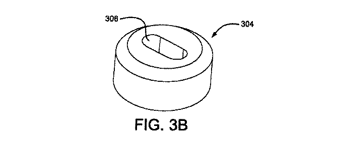
ワイヤフレーム200の製作は、自動ワイヤテンショニングを用いた機械巻込み(winding)を含む種々の手段によって、又は製作中にそれぞれのワイヤから懸吊される錘を用いた手による巻込みによって達成することができる。図3A〜Cには、キー付き中心ピン300とボタン304とが示されている。これらはワイヤフレーム200の製作を補助するために使用することができる。当業者には明らかなように、製造の補助又は工具として使用するのに適した多くの材料がある。中心ピン300を形成するのに使用するための好ましい材料は、コバルト高強度鋼である。ボタン304及び巻込み治具を形成するのに使用するための好ましい材料は、耐食工具鋼である。巻込み治具についてはさらに論じる。図3Aに詳細に示すように、キー付き中心ピン300は溝302を有していてよく、溝は、器具製作中に弾性ワイヤを固定するために使用することができる。キー付き中心ピン300は、ボタン304に設けられた開口306を通して弾性ワイヤをガイドするのに使用されうる。ボタン304の外観は図3B〜Cに示す。ボタン304は、巻込み治具内に確実に嵌入するように、好ましくは底部に凹部を有するように形成される。溝302内に保持されてボタン304内の開口306を通して挿入された弾性ワイヤは、バンパ208とロックループ206とを形成することができる。キー付き中心ピン300はまた、アイレット202,203及び204の形成の際にも使用される。器具の製作中、バンパ208の形成後に、弾性ワイヤがキー付き中心ピン300の周りに巻き付けられ、よって遠位側アイレットが形成されうる。他のアイレット203及び204も同様な態様で形成することができる。一旦キー付き中心ピン300がボタン304内に挿入されると、弾性ワイヤを巻込み治具の溝内に挿入することができる。
Fabrication of the
シール器具100の製作及び加工中に弾性ワイヤを固定して形成するために、巻込み治具を使用することができる。当技術分野では広く知られているように、典型的な巻込み治具を製作することができる。このような巻込み治具を製作するために使用される材料は、前に述べた通りである。好ましい巻込み治具が図4A及び4Bに示されている。図4Aは巻込み治具400の側面図を示している。図4Bは、好ましい巻込み治具400の頂面図を示している。巻込み治具400はアパーチャ402を含有しており、このアパーチャ402は、器具製作中にキー付き中心ピン300及びボタン304を保持するように成形されサイズ設定されてよい。治具表面の溝404は、弾性ワイヤを固定して花弁部212として形成するために使用される。溝404は任意の直径を有していてよいが、しかし弾性ワイヤの外径に対応するようにサイズ設定されるのが好ましい。図5Aに示された一つの実施態様では、巻込み治具組立体は、中央アイレット203と、花弁部組立体と、近位側アイレット204とを形成するために使用することができる。成形されたワイヤは、巻込み治具組立体内で拘束され、加熱され、そして当技術分野において広く知られているように形状セットするように処理されることができる。
A winding jig can be used to fix and form the elastic wire during the manufacture and processing of the
図5Aは、ワイヤフレーム200とシール部材106との複合組立体であるシール器具100の実施態様を示している。シール部材106は、結合剤によってワイヤフレーム200に取り付けることができる。ワイヤフレーム200には結合剤、例えばフッ素化エチレンプロピレン(FEP)又は他の好適な接着剤が塗布されてよい。接着剤は、接触コーティング、粉体コーティング、浸漬コーティング、噴霧コーティング、又は任意の他の適切な手段によって塗布することができる。好ましい実施態様の場合、FEP接着剤は、静電粉体コーティングによって塗布される。シール部材106は、種々様々な材料、例えばDACRON(登録商標)、ポリエステル、ポリエチレン、ポリプロピレン、フルオロポリマー、ポリウレタン、発泡フィルム、シリコーン、ナイロン、シルク、超弾性材料の薄いシート、織布材料、ポリエチレンテレフタレート(PET)、コラーゲン、心膜組織、又は任意の他の生体適合性材料から成っていてよい。一つの実施態様では、シール部材106は、薄い多孔質ePTFE(延伸膨張ポリテトラフルオロエチレン)基体から形成することができる。シール部材106は、欠陥部位封鎖体及び成長中の細胞培地を提供することにより、シール器具100の欠陥部位閉鎖特性を高めるように構成されている。
FIG. 5A shows an embodiment of a
図5Aにはまた、近位側アイレット、遠位側アイレット、及び中央アイレット(202,203及び204)も示されており、これらアイレットはそれぞれシール部材106でカバーされ、そしてフィルムでラッピングされている。アイレット202,203及び204は、器具に対するシール部材の付着を促進するためにフィルムでラッピングされてよい。アイレット202,203及び204をラッピングするために使用されるフィルムは、任意の生体適合性を有する薄い材料であってよいが、しかし好ましくは、1つ又は2つ以上の無孔質FEP層でラミネートされた複数の薄い多孔質ePTFE層から成る材料である。
FIG. 5A also shows a proximal eyelet, a distal eyelet, and a central eyelet (202, 203 and 204), each of which is covered with a
図5Bはシール器具100の一つの実施態様を示しており、この実施態様では、シール器具100は、ワイヤフレーム200を部分的にカバーするシール部材508を含んでいる。部分的にカバーされた器具は、シール部材508で部分的又は全体的にカバーされた遠位側又は近位側のバルブ(bulb)を有していてよい。
FIG. 5B shows one embodiment of the
器具の別の実施態様は、自己センタリング式器具600である。図6に示されているように、自己センタリング式器具600は、ワイヤフレーム200と同様のワイヤフレーム602を含んでいる。自己センタリング式器具600は、ワイヤフレーム602とシール部材604との複合組立体である。ワイヤフレーム602は、ワイヤフレーム200と同じ技術及び材料で製作されてよいが、しかし中央アイレットを有してはいない。ワイヤフレーム602は、遠位側バンパ606と、カバーされた遠位側アイレット608と、カバーされた近位側アイレット610と、ロックループ612とを含む。ワイヤフレーム602の弾性ワイヤのプリセットされた形態は、展開されるとフレームがねじれて、展開中には器具600のセンタリング領域614を形成するのを可能にする。展開中、領域614は、欠陥部位内で自動的にセンタリングすることができ、領域614の両側及び欠陥部位に花弁部から成るディスクを形成する。
Another embodiment of the instrument is a self-centering
図7はシール器具100を、完全に展開された状態で示している。展開中、第3チューブ104の拘束が器具100から取り除かれ、器具はそのプリセットされた形状に戻る。展開及びロック中、ロックループ111は、第1チューブ102の拘束から解放され、そしてそのプリセットされた形状に戻り、近位側アイレット202からカール状に延びている。このように、器具は展開状態においてロックされる。図7はまた、それぞれ近位側アイレット202、中央アイレット203、及び遠位側のアイレット204に対する近位側のディスク、要素702及び遠位側のディスク、要素704の位置を示している。
FIG. 7 shows the
図8は、第1チューブ102と、第3チューブ104と、シール器具100を展開するためのハンドルとを含む搬送システムに取り付けられたシール器具100を示す斜視図である。図8はさらに、第1リニアアクチュエータ802と、フラッシングポート804と、第2リニアアクチュエータ806と、ロック解放アクチュエータ808と、ハウジング810と、ハウジングに設けられた所定の長さを有するスロット812とを示している。第1リニアアクチュエータ802は、種々様々な形態を有していてよく、これに関してはさらに論じることにする。
FIG. 8 is a perspective view showing the
図9A〜Dは、搬送システム、及び取り付けられたシール器具100の種々の構成要素の、使用中の動きを記述するフローチャートである。使用前に搬送システム内にシール器具100を装着することが図9Aに記載されている。搬送システムの構成要素が図8,10及び11に示されている。シリンジ又はその他の好適な手段をフラッシングポート804に取り付け、システムを生理食塩水又はその他の任意の適当なフラッシング材料で満たすことにより、臨床医が搬送システムをフラッシングすることができる。次いで第1リニアアクチュエータ802が、ハウジング810のスロット812内でばね1100に抗して移動せしめられうる。ばね1100は、図示のように形成されていてよく、或いは板ばね、段付きばね、又は当技術分野において広く知られた任意の形として形成されてもよい。この動作は、図11に示されたマンドレル制御レバー1000をスライドロッド1102を中心として、ハウジング810の側方に回転させる。この動作は、第1リニアアクチュエータ802をサイジング挿入体1103の遠位側ノッチ1104から外れるように動かし、そして第2チューブ108が近位側又は遠位側に並進運動するのを防止する。サイジング挿入体1103は、好適な機械特性を有する任意の材料から形成されてよい。
9A-D are flowcharts that describe the movement of the various components of the delivery system and attached
医療器具を搬送するために使用される典型的なハンドル、ハンドル構成要素、ツール又はカテーテルは、一般に知られている材料、例えばポリメチルメタクリレート(PMMA又はアクリル)、ポリスチレン(PS)、アクリロニトリルブタジエンスチレン(ABS)、ポリ塩化ビニル(PVC)、改質ポリエチレンテレフタレートグリコール(PETG)、セルロースアセテートブチレート(CAB)を含む非晶質汎用熱可塑性材料;ポリエチレン(PE)、高密度ポリエチレン(HDPE)、低密度ポリエチレン(LDPE又はLLDPE)、ポリプロピレン(PP)、ポリメチルペンテン(PMP)を含む半結晶性汎用プラスチック;ポリカーボネート(PC)、ポリフェニレンオキシド(PPO)、改質ポリフェニレンオキシド(Mod PPO)、ポリフェニレンエーテル(PPE)、改質ポリフェニレンエーテル(Mod PPE)、熱可塑性ポリウレタン(TPU)を含む非晶質エンジニアリング熱可塑性材料;ポリアミド(PA又はナイロン)、ポリオキシメチレン(POM又はアセタール)、ポリエチレンテレフタレート(PET,熱可塑性ポリエステル)、ポリブチレンテレフタレート(PBT,熱可塑性ポリエステル)、超高分子量ポリエチレン(UHMW−PE)を含む半結晶性エンジニアリング熱可塑性材料;ポリイミド(PI,イミド化プラスチック)、ポリアミドイミド(PAI,イミド化プラスチック)、ポリベンゼンイミダゾール(PBI,イミド化プラスチック)を含む高性能熱可塑性材料;ポリスルホン(PSU)、ポリエーテルイミド(PEI),ポリエーテルスルホン(PES),ポリアリールスルホン(PAS)を含む非晶質高性能熱可塑性材料;ポリフェニレンスルフィド(PPS),ポリエーテルエーテルケトン(PEEK)を含む半結晶性高性能熱可塑性材料;及びフッ素化エチレンプロピレン(FEP)、エチレンクロロトリフルオロエチレン(ECTFE)、エチレン、エチレンテトラフルオロエチレン(ETFE)、ポリクロロトリフルオロエチレン(PCTFE)、ポリテトラフルオロエチレン(PTFE),ポリビニリデンフルオリド(PVDF)、ペルフルオロアルコキシ(PFA)を含む半結晶性高性能熱可塑性材料、フルオロポリマーを含むことができる。他の一般に知られている医療品等級材料は、エラストマー有機ケイ素ポリマー、ポリエーテルブロックアミド、又は熱可塑性コポリエール(PEBAX)、及び例えばステンレス鋼及びニッケル/チタン合金等の金属を含む。 Typical handles, handle components, tools or catheters used to deliver medical devices are commonly known materials such as polymethyl methacrylate (PMMA or acrylic), polystyrene (PS), acrylonitrile butadiene styrene ( Amorphous general purpose thermoplastic materials including ABS), polyvinyl chloride (PVC), modified polyethylene terephthalate glycol (PETG), cellulose acetate butyrate (CAB); polyethylene (PE), high density polyethylene (HDPE), low density Semi-crystalline general purpose plastics including polyethylene (LDPE or LLDPE), polypropylene (PP), polymethylpentene (PMP); polycarbonate (PC), polyphenylene oxide (PPO), modified polyphenylene oxide (M d PPO), polyphenylene ether (PPE), modified polyphenylene ether (Mod PPE), amorphous engineering thermoplastic materials including thermoplastic polyurethane (TPU); polyamide (PA or nylon), polyoxymethylene (POM or acetal) Semi-crystalline engineering thermoplastic materials including polyethylene terephthalate (PET, thermoplastic polyester), polybutylene terephthalate (PBT, thermoplastic polyester), ultrahigh molecular weight polyethylene (UHMW-PE); polyimide (PI, imidized plastic), High performance thermoplastic materials including polyamidoimide (PAI, imidized plastic), polybenzeneimidazole (PBI, imidized plastic); polysulfone (PSU), polyetherimide (P I), amorphous high performance thermoplastic material containing polyethersulfone (PES), polyarylsulfone (PAS); semi-crystalline high performance thermoplastic material containing polyphenylene sulfide (PPS), polyetheretherketone (PEEK) Fluorinated ethylene propylene (FEP), ethylene chlorotrifluoroethylene (ECTFE), ethylene, ethylene tetrafluoroethylene (ETFE), polychlorotrifluoroethylene (PCTFE), polytetrafluoroethylene (PTFE), polyvinylidene fluoride (PVDF), semi-crystalline high performance thermoplastic materials including perfluoroalkoxy (PFA), fluoropolymers. Other commonly known medical grade materials include elastomeric organosilicon polymers, polyether block amides, or thermoplastic copolyales (PEBAX), and metals such as stainless steel and nickel / titanium alloys.
サイジング挿入体1103に設けられた遠位側ノッチ1104及び近位側ノッチ1106は、ハウジングスロット812内に第1リニアアクチュエータ802を位置決めするのを補助するのに使用されうる。2つのノッチ1104及び1106間の距離は、シール器具100が、搬送システムへの装着前に、第2チューブ108上に伸長させられたときのシール器具100の長さであってよい。サイジング挿入体1103は、種々の器具長さに対応するようにサイズ設定することができ、好ましくは約22.28cm長からであり、この場合遠位側ノッチ1104の近位端と近位側ノッチ1106の近位端との間隔は約6.25〜13.32cmからである。ノッチ1104及び1106は、任意の形状を有していてよいが、しかし好ましくは方形である。
A
次いで、第1リニアアクチュエータ802が、ハウジング810の近位端に向かってスロット812内の中点まで動かされる。この動作は、第1チューブ102を近位側に動かし、シール器具100の近位端を近位に動かし、ひいてはシール器具100を伸長させる。第1リニアアクチュエータ802は任意の形状(レバー、ボール)であってよいが、しかし好ましくは臨床医の親指に対応するように成形されている。第1リニアアクチュエータ802は、好適な機械特性を有する任意の材料から製作されていてよいが、しかしサイジング挿入体1103の材料と同様の材料であることが好ましい。第1リニアアクチュエータ802の特徴は、回収コード110を固定するために第1リニアアクチュエータ802の上側部分に形成された凹状歯列である。この特徴は好ましいものであるがしかし任意である。歯列は、任意の蛇行路として形成することもでき、或いは、シール器具100の装着中、展開中、又は回収中に回収コード110に対する抵抗性を形成するのに望ましい任意の形状を有することもできる。回収コードロック803の底面には、対応する突出歯列(図示せず)が形成されてよい。これら歯列は噛み合って、回収コードを固く保持することができる。小さな直径のコードを固定するための当技術分野において広く知られた他の方法を用いることもでき、これに関しては下記セクションで詳細に論じる。
The first
次いで、器具が第3チューブ104内に装着されるまで、第1リニアアクチュエータ802がさらに近位側に動かされる。この動作中、ばね1100が第1リニアアクチュエータ802及びマンドレル制御レバー1000をスロット812の左側に押し、そしてサイジング挿入体1103の近位側ノッチ1106内に押し込む。第2チューブ108は、シール器具100及び第1チューブ102と一緒に近位側に自由に動く。第1リニアアクチュエータ802が近位側に動くのに伴って、第2チューブ108とシール器具100と第1チューブ102とは、第3チューブ104内にスライド又は並進運動する。第1リニアアクチュエータ802がその最近位位置に達した後、システムは再び上記のように生理食塩水でフラッシングすることができる。
The first
第1リニアアクチュエータ802の別の実施態様が図12A〜Cに示されている。図12Aは、別のリニアアクチュエータ1108を、回収コードロック位置にある状態で示す斜視図である。リニアアクチュエータ1108は、リニアアクチュエータ802と構造が類似しているが、しかし回収コードロッキングリング1110及び回収コード溝1112を特徴としている。図12Bは別の実施態様1114を示しており、この実施態様では、操作を容易にすべくリニアアクチュエータの側方を超えて延びているサムホイール1116を有するように構成されている。リニアアクチュエータサムホイール1116は、ねじ山付きポスト1118にねじ込まれ、このポストの周りには回収コードが巻かれる。実施態様1114も回収コード溝1120を含有しており、この回収コード溝を通して、回収コードは、ねじ山付きポスト1118の周りに固定される前にガイドされる。図12Cは更なる別の実施態様1122が示されており、この実施態様は、側方で嵌められたねじ山付きサムホイール1124を利用する。このサムホイールの周りには回収コードが巻かれ、そしてねじ山付きポスト1124を、アクチュエータ1122の側方に設けられたねじ山付きアパーチャ(図示せず)内に挿入するという動作によって、回収コードはアクチュエータ1122に固定される。回収コードは、ねじ山付きポスト1124の周りに手繰り込まれる前に、回収コード溝1126を通して挿入される。図12Dにはさらに別の実施態様1128が示されている。実施態様1128は、成形サムホイール1130を備えたリニアアクチュエータを示している。サムホイール1130は、リニアアクチュエータのエッジを僅かに超えて延びており、リニアアクチュエータの操作を容易にする。回収コードが、コード溝1132を通して挿入され、ねじ山付きポスト(図示せず)の周りに巻かれる。次いで、成形サムホイール1130がねじ山付きポストに固定され、回収コードを固定する。
Another embodiment of the first
欠陥部位内にシール器具100を展開することが図9Bに記載されている。第1リニアアクチュエータ802をストッパに達するまで遠位側に動かす。この動作は第1チューブ102及び第2チューブ108を、第3チューブ104内部で遠位側に動かす。次いで、リニアアクチュエータ802がばね1100に抗してスロット812内で右側に動かされなければならない。リニアアクチュエータ802が右側に動かされたら、マンドレル制御レバー1000がスライダロッド1102上で回転する。この動作は、リニアアクチュエータ802を、サイジング挿入体1103の近位側ノッチ1106から解放する。この動作の後、リニアアクチュエータ802がさらに遠位側に並進運動せしめられる。このことは、第1チューブ102とシール器具100の近位側のアイレット202とを遠位側に動かす。またこのような動作によって、移動が防止されているシール器具100の遠位端にも影響が及ぼされる。第1チューブ102は第3チューブ104から器具をガイドすることにより、欠陥部位内に器具を展開する。リニアアクチュエータ802を遠位側へ、スロット812の端部に動かす結果、シール器具全体が展開される。当業者には明らかなように、上記ステップを、シール器具100の最適な配置を可能にするように、或る特定の時点で中断して逆転することもできる。
Deploying the
図9Cに示されたフローチャート内には器具をロックすることが記載されている。回収コードロック803は第1リニアアクチュエータ802からスナップ結合が解除される。臨床医は、取り付けられたロック解放アクチュエータ808を握ることにより、第2リニアアクチュエータ806を把持し、これをハウジング810の中央に向かって押す。第2リニアアクチュエータ806は任意のサイズ又は形状を有していてよいが、しかしハウジング810の長手方向表面に設けられたスロット1002内部に嵌入するようにサイズ設定されることが好ましい。リニアアクチュエータ806にはスナップ結合によって、ロック解放アクチュエータ808が装着されている。ロック解放アクチュエータ808をリニアアクチュエータ806に留めるには任意の装着手段、例えば接着剤又は成形部分のような構造で十分である。第2リニアアクチュエータ806及びロック解放アクチュエータ808の両方に適した材料は、好適な機械特性を有する任意の材料であってよいが、しかし前述のハンドル構成要素と同様であることが好ましい。ロック解放アクチュエータ808は、使用者が器具を確実に把持するのを可能にするように構成されている。ロック解放アクチュエータ808の側方に設けられた突起によって把持を補助することができる。これら突起は、ロック解放アクチュエータ808と同様の材料から形成されてよく、或いは、摩擦係数が高い材料又はロック解放アクチュエータ808よりもコンプライアントな材料から形成されてもよい。これら突起は、器具の把持をさらに補助するために、上記材料と相俟って、グレーティング(grating)、粗面化、隆起デザイン、又は表面のスタライエーション(striation)によって形成することもできる。ロック解放アクチュエータ808の表面上のこれら特徴は、把持用突起を用いることなしに、把持を補助するために用いることもでき、また、第2リニアアクチュエータ806の側面に直接に取り付けることもできる。スロット1002は、シール器具のロック解放まで、第2リニアアクチュエータ806を最遠位位置に保持するためのストッパを有するように形成されていてよい。図10及び11に、波形区域の形の好ましいストッパが示されているが、しかしストッパは機械的ストッパの任意の形式であってよい。スロット1002は、任意の長さを有していてよいが、しかし近位側に並進運動するのに十分な長さ、つまり第2リニアアクチュエータ806の幅プラス約3.18cmを有していることが好ましい。スロット1002は、第2リニアアクチュエータ806に対応する任意の形状を有していてよい。
Locking the instrument is described in the flowchart shown in FIG. 9C. The
第2リニアアクチュエータ806の別の実施態様が図13A及び13Bに示されている。ロック解放アクチュエータ808を把持して第2リニアアクチュエータ806を作動させる代わりに、回転可能なロック解放アクチュエータ1300を把持して回転させることにより、ロック解放に影響を与える。回転可能なロック解放アクチュエータ1300は窓1302を含有している。窓1302は、第1リニアアクチュエータ802の前進運動を防止する。回転させられると、ロック解放アクチュエータ1300は、図10に示されたロック解放アクチュエータ808と同じ動作を可能にする。
Another embodiment of the second
臨床医は、第2リニアアクチュエータ806を把持したら、第2リニアアクチュエータ806を近位側に動かすことができる。この動作は結果として、第3チューブ104、マンドレル制御レバー1000、サイジング挿入体1103、及び第2チューブ108の近位側への運動をもたらす。第2チューブ108は、器具のアイレット間から近位側に移動する。この動作を達成する別の方法は、第2リニアアクチュエータ806の代わりにハンドルの遠位端にねじりメカニズムを提供することである。このねじりメカニズムは、第3チューブ104、マンドレル制御レバー1000、サイジング挿入体1103、及び第2チューブ108の、第2リニアアクチュエータ806と同じ運動を可能にするスロットを備える。
Once the clinician grasps the second
一旦ロック解放を達成したら、回収コードロック803をねじることによって、これを第1リニアアクチュエータ802から取り外し、そして回収コード110が搬送システムから解放されるまで引っ張る。回収コード110は、回収コードロック803に一方の端部で取り付けられる。回収コード110は、好適な機械特性を有する任意の材料、例えばKevlar(登録商標)、可撓性金属ワイヤ、及びポリマーなどから製作することができる。回収コード110のための好ましい材料は、ePTFE繊維である。回収コードロック803は、種々様々な形状及びサイズで形成されてよい。可能な回収コードロックは、リニアアクチュエータ802に回収コードが通過するリニアアクチュエータスロットを提供するように構成されてよい。1つの形態において、回収コードは、リニアアクチュエータ802内に配置されたサムホイールの軸内のスロット又は孔にコードを通し、そしてサムホイールをねじることでこれを締め付けることにより固定される。別の形態はスライドロックを提供する。このスライドロックは、ロックとリニアアクチュエータ802との間に摩擦を用いて回収コードを束縛する。好ましい構成は、図11に示された回収コードロックに形成された歯列間に回収コードを固定することである。
Once the lock release is achieved, it is removed from the first
回収コードロック803を製作するのに適した材料は、ハウジング810及び他のハンドル構成要素を製作するために使用される材料と同様である。前述のように、回収コードロック803は好ましくは、回収コード110を把持する目的で、リニアアクチュエータ802内の刻み目に対応する歯列又は突起を有している。回収コードロック803は、回収コード110が固定されるのを可能にするように、種々の形状で製作することができる。好ましい形態は、回収コード110が手繰り通されて結ばれるのを可能にするように、回収コードロック803を通るアパーチャを含む。回収コードロック803をねじった後、回収コード110が搬送システムから取り外されるまでこれを引っ張る。
Suitable materials for fabricating the
図9Cに記載されたステップ4の前に、シール器具100は、図9Dに示されたフローチャートに記載されているように回収することができる。回収コードロック803は、第1リニアアクチュエータ802内にスナップ結合することができる。このことは、回収コード110を所定の場所にロックするのに役立つ。次いで臨床医は、第1リニアアクチュエータ802をスロット812の右縁部に動かす。第1リニアアクチュエータ802はスロット812内で右側に動き、ばね1100を押圧し、これに対して、マンドレル制御レバー1000はスライダロッド1102上で回転してハンドルの右側に動く。スライダロッド1102は好ましくは円形断面を有するが、しかし当業者に明らかなように種々様々な断面形状(例えば正方形又は三角形)を許容することができる。スライダロッド1102は、図14A及びBに示されているようなクラウンばね1400の形状を成して形成することもできる。ばねは、リニアアクチュエータの前後並進運動を可能にするように、リニアアクチュエータを通るスロット1402内に挿入することができる。ばね1100の別の実施態様は、図15によって示された第1リニアアクチュエータ802の一体部分1500として成形されたばねであってよい。ばね1100の別の実施態様は図16に示されている。この形態において、ばね1600はハウジング810に取り付けられており、そして主要位置において第1リニアアクチュエータ802を押す。上述のように、ばね又は成形部分として使用するのに適した材料が当業者には明らかである。第1リニアアクチュエータ802は、遠位側ノッチ1104から解放されており、第2チューブ108は移動を防止されている。第1リニアアクチュエータは、臨床医が第1チューブ102を近位側に動かすことにより、近位側に動かされる。この動作は、シール器具100の近位端を並進運動させ、器具100を近位側に伸長させ、そして器具が第3チューブ104内に引き込まれるのを可能にする。
Prior to step 4 described in FIG. 9C, the
或いは、シール器具100は、次のように回収することもできる。回収コードロック802は、第1リニアアクチュエータ802内にスナップ結合することができる。回収ルアー814をねじ外し、ハンドル800から搬送カテーテル104を分離する。次いでハンドル800全体を把持し、そして搬送カテーテル104を所定の場所に保持しながらハンドルを引き抜くことにより、器具を回収することができる。この動作は、器具100が、搬送カテーテル104を通して強制的に引き抜かれるようにする。
Alternatively, the
本発明の範囲を限定することなしに、下記実施例は、本発明の種々様々な実施態様がどのように形成及び/又は使用されることができるかを例示する。 Without limiting the scope of the invention, the following examples illustrate how various embodiments of the invention can be formed and / or used.
[実施例1]
下記構成要素及び組み立てプロセスを用いて、図1と同様のシール器具を製造した。
[Example 1]
A sealing device similar to that of FIG. 1 was manufactured using the following components and assembly process.
下記特性を有する、延伸膨張ポリテトラフルオロエチレン材料を得た。
メタノール泡立ち点 6.89KPa(1psi)
質量/面積 2.2グラム/平方メートル
長手方向最大荷重 0.063kg/mm(1.6kg/インチ)
厚さ 0.0076mm(0.0003インチ)
長手方向最大引張り強度 634MPa(92000psi)
An expanded polytetrafluoroethylene material having the following characteristics was obtained.
Methanol bubble point 6.89 KPa (1 psi)
Mass / Area 2.2 grams / square meter Maximum longitudinal load 0.063 kg / mm (1.6 kg / inch)
Thickness 0.0076mm (0.0003 inch)
Maximum longitudinal tensile strength 634 MPa (92,000 psi)
下記試験方法及び設備を用いて、上述の特性を測定した。メタノール泡立ち点は、直径が25.4mm(1インチ)のフット、ランプ速度1.37KPa/秒(0.2psi/秒)、及びメタノールの液状媒体を有するカスタムメイドの機械を使用して測定した。材料の長さ及び幅は金属ルーラを使用して測定した。質量/面積は、914×127mm(36×5インチ)の試料で、はかり(Model GF-400 Top Loader Balance, ANG, San Jose CA.)を使用して測定した。長手方向最大荷重は10kgのロードセルを備えた材料試験機械(Model 5564, Instron, Grove City, PA)を使用して測定した。ゲージ長は25.4mm(1インチ)であり、クロスヘッド速度は25mm/分であった。試料幅は25.4mm(1インチ)であった。長手方向引張り試験測定値は材料の長さ方向において求めた。フット直径6.35mm(1/4インチ)の厚さゲージ(Mitutoyo Digital Indicator 547-400)を使用して厚さを測定した。長手方向マトリックス引張り強度(MTS)は次の等式を使用して計算し、密度は式:密度=質量/体積を用いて計算した。
下記特性を有する、FEP(フッ素化エチレンプロピレン)材料薄層を有する延伸膨張ポリテトラフルオロエチレンを得た。
質量/面積 36.1グラム/平方メートル
最大荷重 長手方向0.496kg/mm(12.6kg/インチ)
最大荷重 横方向0.0118kg/mm(0.3kg/インチ)
厚さ 0.0305mm(0.0012インチ)
An expanded polytetrafluoroethylene having a thin FEP (fluorinated ethylene propylene) material layer having the following characteristics was obtained.
Mass / Area 36.1 grams / square meter Maximum load Longitudinal direction 0.496 kg / mm (12.6 kg / inch)
Maximum load lateral direction 0.0118kg / mm (0.3kg / inch)
Thickness 0.0305mm (0.0012 inch)
下記試験方法及び設備を用いて、上述の特性を測定した。試料面積が914×25mm(36x1インチ)試料の精密分析はかり(Model GF-400 Top Loader Balance, ANG, San Jose CA.)を用いて材料を秤量した。材料の長さ及び幅は金属ルーラを使用して測定した。材料厚はフット直径6.35mm(1/4インチ)の厚さゲージ(Mitutoyo Digital Indicator 547-400)を使用して測定した。横方向最大荷重は10kgのロードセルを備えた材料試験機械(Model 5564, Instron, Grove City, PA)を使用して測定した。試料幅は25.4mm(1インチ)、ゲージ長は25.4mm(1インチ)、そしてクロスヘッド速度は25mm/分であった。長手方向最大荷重は200kgのロードセルを備えた材料試験機械(Model 5564, Instron, Grove City, PA)を使用して測定した。試料幅は25.4mm(1インチ)、ゲージ長は25.4mm(1インチ)、そしてクロスヘッド速度は25mm/分であった。長手方向引張り試験測定値は材料の長さ方向において求め、そして横方向引張り試験測定値は長さ方向に対して直交方向において求めた。 The above-mentioned characteristics were measured using the following test method and equipment. The material was weighed using a precision analytical scale (Model GF-400 Top Loader Balance, ANG, San Jose Calif.) With a sample area of 914 × 25 mm (36 × 1 inch). The length and width of the material was measured using a metal ruler. The material thickness was measured using a thickness gauge (Mitutoyo Digital Indicator 547-400) with a foot diameter of 6.35 mm (1/4 inch). The maximum lateral load was measured using a material testing machine (Model 5564, Instron, Grove City, PA) equipped with a 10 kg load cell. The sample width was 25.4 mm (1 inch), the gauge length was 25.4 mm (1 inch), and the crosshead speed was 25 mm / min. The maximum longitudinal load was measured using a material testing machine (Model 5564, Instron, Grove City, PA) equipped with a 200 kg load cell. The sample width was 25.4 mm (1 inch), the gauge length was 25.4 mm (1 inch), and the crosshead speed was 25 mm / min. Longitudinal tensile test measurements were determined in the length direction of the material and transverse tensile test measurements were determined in a direction orthogonal to the length direction.
直径約0.23mmの所定の長さの10%白金ドローン−フィルド型ニチノールワイヤ(Fort Wayne Metals, Fort Wayne, IN)を先ず入手することによって、遠位側アイレットを形成した。このワイヤを「第1ワイヤ」とラベル付けした。第1ワイヤの自由端を二重にすることにより、オープンエンドループを形成し、このオープンエンドループをボタン内に挿入した。次いで、ボタンをキー付き中心ピン上に挿入した。ボタンは、キー付き中心ピンを収容するための、中心を通る開口を有するように、そして巻込み治具内に確実に位置するのを可能にする構成要件を有するように成形した。キー付き中心ピン(長軸約0.51mm及び短軸約0.25mm、並びに長さ約10.16mm)を次いで巻込み治具の中心に挿入した。キー付き中心ピンは高強度鋼(Super Cobalt HSS Tool Bit, MSC#56424278, Seco Fagersta)から製作した。鋼を製造業者の指示書に従って1時間にわたって1475°Fで調質した。巻込み治具及びボタンを耐食性工具鋼から自社で製作した。 A distal eyelet was formed by first obtaining a 10% platinum drone-filled Nitinol wire (Fort Wayne Metals, Fort Wayne, IN) of a predetermined length of about 0.23 mm in diameter. This wire was labeled “first wire”. An open end loop was formed by doubling the free end of the first wire, and this open end loop was inserted into the button. The button was then inserted over the keyed center pin. The button was shaped to have an opening through the center to accommodate the keyed center pin and to have a configuration requirement that allows it to be securely positioned within the winding jig. A keyed center pin (major axis about 0.51 mm and minor axis about 0.25 mm, and length about 10.16 mm) was then inserted into the center of the winding jig. The key pin with key is made of high strength steel (Super Cobalt HSS Tool Bit, MSC # 56424278, Seco Fagersta). The steel was tempered at 1475 ° F. for 1 hour according to the manufacturer's instructions. The winding jig and button were manufactured in-house from corrosion-resistant tool steel.
第2長さの同じタイプのドローン−フィルド型ニチノールワイヤを入手し、これを「第5ワイヤ」とラベル付けした。第1ワイヤ、第5ワイヤ、及びさらなる3本のワイヤを、ワイヤ端部に錘を取り付けることにより緊張させた。次いで第1ワイヤ及び第5ワイヤを、第1ワイヤの自由端部の周りに1回転完全に巻き付けた。3本のさらなるワイヤを巻込み治具に導入し、5本すべてのワイヤを第1ワイヤの自由端部の周りに、約1.98mmの高さまで巻き付けた。 A second length of the same type of drone-filled Nitinol wire was obtained and labeled "Fifth Wire". The first wire, the fifth wire, and three additional wires were tensioned by attaching weights to the wire ends. The first wire and the fifth wire were then fully wound around the free wire's free end. Three additional wires were introduced into the winding jig and all five wires were wound around the free end of the first wire to a height of about 1.98 mm.
次いで、5本のワイヤを分離して巻込み治具の周縁に設けられた半径方向溝内にこれらを固定することにより、遠位側ディスクを形成した。半径は15mmの寸法で形成した。それぞれのワイヤは遠位側ディスクの1つの花弁部を形成した。花弁部の曲率半径は、ワイヤ内の曲げ鋭角を最小限に抑えるために最大化した。 Subsequently, the five wires were separated and fixed in a radial groove provided at the periphery of the winding jig to form a distal disk. The radius was 15 mm. Each wire formed one petal portion of the distal disk. The radius of curvature of the petals was maximized to minimize the bending angle in the wire.
ワイヤを1つにまとめ、そして第1ワイヤの自由端部及びキー付き中心ピンの周りにこれらを約1.98mmの高さまで巻き付けることにより、中央アイレットを形成した。次いでこれらワイヤを分離し、巻込み治具の周縁に設けられた半径方向溝内に固定して、半径15mmの近位側ディスクを形成した。 The central eyelet was formed by bringing the wires together and wrapping them around the free end of the first wire and the keyed center pin to a height of about 1.98 mm. These wires were then separated and secured in radial grooves provided at the periphery of the winding jig to form a proximal disk with a radius of 15 mm.
再び5本のワイヤを1つにまとめ、そして第1ワイヤの自由端部及びキー付き中心ピンの周りにこれらを約1.98mmの高さまで巻き付けることにより、近位側アイレットを形成した。次いで5本のワイヤを分離し、そしてステンレス鋼板をワイヤの上側に設置し、プレートをねじでロックすることによって固定した。次いで、第1ワイヤの自由端を、直径約3.18mmのステンレス鋼ピンの周りに1回転だけ巻き付け、そして他の5本のワイヤと同様に固定した。 The proximal eyelet was formed by bringing the five wires together again and wrapping them around the free end of the first wire and the keyed center pin to a height of about 1.98 mm. The five wires were then separated and secured by placing a stainless steel plate on top of the wires and locking the plate with screws. The free end of the first wire was then wrapped around the stainless steel pin about 3.18 mm in diameter for one revolution and secured in the same manner as the other five wires.
シール器具を含む治具を次いで安定化固定具から取り外し、そして炉(Blue M SPX Electric Forced Air Convection Oven)内に入れ、そしてワイヤを当技術分野において広く知られているように熱的に形状セットした。器具及び治具を次いで水で急冷した。固定されたワイヤを固定板から解放し、器具を冷却して治具及びキー付き中心ピンから取り出した。次いで、器具を、偏平PEEK(ポリエーテルエーテルケトン)片上に設置し、そして遠位側アイレットの外径まで手でトリミングした。ロックループを、完全な1回転をちょうど超える点まで手でトリミングし、そして近位側アイレット及び中央アイレットを通して引張った。 The jig containing the sealing device is then removed from the stabilization fixture and placed in a furnace (Blue M SPX Electric Forced Air Convection Oven) and the wire is thermally set as is widely known in the art. did. The instrument and jig were then quenched with water. The fixed wire was released from the fixed plate, the instrument was cooled and removed from the jig and keyed center pin. The instrument was then placed on a flat PEEK (polyetheretherketone) piece and hand trimmed to the outer diameter of the distal eyelet. The lock loop was manually trimmed to a point just over one full revolution and pulled through the proximal and central eyelets.
器具をPEEKマンドレルから、楕円横断面を有するキー付きステンレス鋼プロセスマンドレル上に押し出した。このマンドレルは、近位側アイレットと中央アイレットとの間に45°時計回りねじりを有し、そして中央アイレットと遠位側アイレットとの間に第2の45°時計回りねじりを有するように、楕円横断面の偏平ステンレス鋼ワイヤ(Ft. Wayne Metals, Fort Wayne, IN)から製造した。 The instrument was extruded from the PEEK mandrel onto a keyed stainless steel process mandrel having an elliptical cross section. The mandrel is elliptical so as to have a 45 ° clockwise twist between the proximal eyelet and the central eyelet and a second 45 ° clockwise twist between the central eyelet and the distal eyelet. Manufactured from flat stainless steel wire (Ft. Wayne Metals, Fort Wayne, IN) in cross section.
次いで、プロセスマンドレル及び器具を、FEP粉体コーター(C-30, Electrostatic Technology, Inc., Bradford, CN)内に配置された安定化固定具に設置し、完全に塗布されるまで処理した。過剰なFEP粉体を器具から除去した。FEPはロックループ、プロセスマンドレル及びバンパからバキューミングした。プロセスマンドレル及び器具を安定化固定具から取り出し、炉内に入れ、そして当技術分野において広く知られているようにFEP塗膜を硬化させるようにベーキングした。 The process mandrel and instrument were then placed on a stabilizing fixture located in a FEP powder coater (C-30, Electrostatic Technology, Inc., Bradford, CN) and processed until fully applied. Excess FEP powder was removed from the instrument. The FEP was vacuumed from a lock loop, process mandrel and bumper. The process mandrel and instrument were removed from the stabilizing fixture, placed in an oven, and baked to cure the FEP coating as is widely known in the art.
中空コアフィルムマンドレル(35.99mm外径、76.2cm長のステンレス鋼)を入手した。スリット幅22.22mmの膨張延伸ポリテトラフルオロエチレン材料を入手し、スパイラルラッピング機械に装着した。機械は、任意の所望の角度、張力及び速度でPTFE(ポリテトラフルオロエチレン)材料をラッピングするように自社で製作した。マンドレルをラッピング機械上に装着し、そして中空コアマンドレルの周面に3回ラッピングした。次いで材料をマンドレルの長さに対応して約8°の角度でマンドレルにラッピングした。ラッピング方向を逆転して、同じ角度で材料をオーバーラッピングした。継ぎ目をオフセットしながら、第3及び第4の層を同様にラッピングした。マンドレルをラッピング機械から取り出し、炉内に挿入し、そして45分間にわたって370℃でベーキングした。ラッピングされたマンドレルを炉から取り出し、そして室温まで冷やしておいた。結果として得られたPTFEチューブをマンドレルから取り出した。 A hollow core film mandrel (35.99 mm outer diameter, 76.2 cm long stainless steel) was obtained. An expanded and expanded polytetrafluoroethylene material having a slit width of 22.22 mm was obtained and mounted on a spiral wrapping machine. The machine was made in-house to wrap PTFE (polytetrafluoroethylene) material at any desired angle, tension and speed. The mandrel was mounted on a wrapping machine and wrapped three times around the circumference of the hollow core mandrel. The material was then wrapped onto the mandrel at an angle of about 8 ° corresponding to the length of the mandrel. The wrapping direction was reversed and the material was overlapped at the same angle. The third and fourth layers were similarly wrapped with the seam offset. The mandrel was removed from the wrapping machine, inserted into a furnace and baked at 370 ° C. for 45 minutes. The wrapped mandrel was removed from the furnace and allowed to cool to room temperature. The resulting PTFE tube was removed from the mandrel.
次いでPTFEチューブを約140mmに切断し、そして手で所望の長さ155mmまで延伸させた。次いでPTFEチューブをフレームを覆うように引張った。次いでPTFEチューブを中央アイレット上にクリンピングし、次いで遠位側及び近位側のアイレット上にクリンピングした。 The PTFE tube was then cut to approximately 140 mm and stretched by hand to the desired length of 155 mm. The PTFE tube was then pulled over the frame. The PTFE tube was then crimped on the central eyelet and then crimped on the distal and proximal eyelets.
次いで、中央アイレットから始めてアイレットの周りに4回、FEP(フッ素化エチレンプロピレン)薄層を含む延伸膨張ポリテトラフルオロエチレンをラッピングした。ラッピングされたアイレットをはんだごてで所定の場所に留めた。次いでPTFEチューブを320℃で3分間にわたってヒートセットし、そして近位側及び遠位側のエアレットの最外点までトリミングした。器具をマンドレルから取り出した。 The expanded polytetrafluoroethylene containing a thin FEP (fluorinated ethylene propylene) layer was then wrapped four times around the eyelet starting from the central eyelet. The wrapped eyelet was held in place with a soldering iron. The PTFE tube was then heat set at 320 ° C. for 3 minutes and trimmed to the outermost point of the proximal and distal airlets. The instrument was removed from the mandrel.
[実施例2]
下記構成要素及び組み立てプロセスを用いて、図6と同様のシール器具を製造した。
[Example 2]
A sealing device similar to that of FIG. 6 was manufactured using the following components and assembly process.
実施例1に記載されているのと同様の延伸膨張ポリテトラフルオロエチレン材料、及びFEP(フッ素化エチレンプロピレン)材料薄層を有する延伸膨張ポリテトラフルオロエチレンを得た。 The same expanded polytetrafluoroethylene material as described in Example 1 and expanded polytetrafluoroethylene having a thin FEP (fluorinated ethylene propylene) material layer were obtained.
直径約0.23mmの所定の長さの10%白金ドローン−フィルド型ニチノールワイヤ(Fort Wayne Metals, Fort Wayne, IN)を先ず入手することによって、遠位側アイレットを形成した。このワイヤを「第1ワイヤ」とラベル付けした。第1ワイヤの自由端を二重にすることにより、オープンエンドループを形成し、このオープンエンドループをボタン内に挿入した。次いで、ボタンをキー付き中心ピン上に挿入した。ボタンは、キー付き中心ピンを収容するための、中心を通る開口を有するように、そして巻込み治具内に確実に位置するのを可能にする構成要件を有するように成形した。キー付き中心ピン(長軸約5.79mm及び短軸約0.25mm、並びに長さ約10.16mm)を次いで巻込み治具の中心に挿入した。キー付き中心ピンは高強度鋼(Super Cobalt HSS Tool Bit, MSC#56424278, Seco Fagersta)から製作した。巻込み治具及びボタンを耐食性工具鋼から自社で製作した。 A distal eyelet was formed by first obtaining a 10% platinum drone-filled Nitinol wire (Fort Wayne Metals, Fort Wayne, IN) of a predetermined length of about 0.23 mm in diameter. This wire was labeled “first wire”. An open end loop was formed by doubling the free end of the first wire, and this open end loop was inserted into the button. The button was then inserted over the keyed center pin. The button was shaped to have an opening through the center to accommodate the keyed center pin and to have a configuration requirement that allows it to be securely positioned within the winding jig. A keyed center pin (major axis about 5.79 mm and minor axis about 0.25 mm, and length about 10.16 mm) was then inserted into the center of the winding jig. The key pin with key is made of high strength steel (Super Cobalt HSS Tool Bit, MSC # 56424278, Seco Fagersta). The winding jig and button were manufactured in-house from corrosion-resistant tool steel.
第2長さの同じタイプのドローン−フィルド型ニチノールワイヤを入手し、これを「第5ワイヤ」とラベル付けした。第1ワイヤ、第5ワイヤ、及びさらなる3本のワイヤを、ワイヤ端部に錘を取り付けることにより緊張させた。次いで第1ワイヤ及び第5ワイヤを、第1ワイヤの自由端部の周りに1回転完全に巻き付けた。3本のさらなるワイヤを巻込み治具に導入し、5本すべてのワイヤを第1ワイヤの自由端部の周りに、約1.98mmの高さまで巻き付けた。 A second length of the same type of drone-filled Nitinol wire was obtained and labeled "Fifth Wire". The first wire, the fifth wire, and three additional wires were tensioned by attaching weights to the wire ends. The first wire and the fifth wire were then fully wound around the free wire's free end. Three additional wires were introduced into the winding jig and all five wires were wound around the free end of the first wire to a height of about 1.98 mm.
次いで、5本のワイヤを分離して巻込み治具の周縁に設けられた半径方向溝内にこれらを固定することにより、器具を形成した。半径は15mmの寸法で形成した。それぞれのワイヤは巻込み治具の周りに完全に1回転させた。 The instrument was then formed by separating the five wires and fixing them in radial grooves provided at the periphery of the winding jig. The radius was 15 mm. Each wire was rotated once around the winding jig.
再び5本のワイヤを1つにまとめ、そして第1ワイヤの自由端部及びキー付き中心ピンの周りにこれらを約1.981mmの高さまで巻き付けることにより、近位側アイレットを形成した。次いで5本のワイヤを分離し、そしてステンレス鋼板をワイヤの上側に設置し、プレートをねじでロックすることによって固定した。次いで、第1ワイヤの自由端を、直径約3.18mmのステンレス鋼ピンの周りに1回転だけ巻き付け、そして他の5本のワイヤと同様に固定した。 The proximal eyelet was formed by bringing the five wires together and wrapping them around the free end of the first wire and the keyed center pin to a height of about 1.981 mm. The five wires were then separated and secured by placing a stainless steel plate on top of the wires and locking the plate with screws. The free end of the first wire was then wrapped around the stainless steel pin about 3.18 mm in diameter for one revolution and secured in the same manner as the other five wires.
シール器具を含む治具を次いで安定化固定具から取り外し、そして炉(Blue M SPX Electric Forced Air Convection Oven)内に入れ、そしてワイヤを当技術分野において広く知られているように熱的に形状セットした。器具及び治具を次いで水で急冷した。固定されたワイヤを固定板から解放し、器具を冷却して治具及びキー付き中心ピンから取り出した。ロックループを、完全な1回転をちょうど超える点まで手でトリミングし、そして近位側アイレット及び中央アイレットを通して引張った。 The jig containing the sealing device is then removed from the stabilization fixture and placed in a furnace (Blue M SPX Electric Forced Air Convection Oven) and the wire is thermally set as is widely known in the art. did. The instrument and jig were then quenched with water. The fixed wire was released from the fixed plate, the instrument was cooled and removed from the jig and keyed center pin. The lock loop was manually trimmed to a point just over one full revolution and pulled through the proximal and central eyelets.
器具をPEEKマンドレルから、楕円横断面を有するキー付きステンレス鋼トランスファーマンドレル上に押し出した。このマンドレルは、楕円横断面の偏平ステンレス鋼ワイヤ(Ft. Wayne Metals, Fort Wayne, IN)から製造した。次いで、器具をトランスファーマンドレルの一方の端部から部分的に取り出した。取り出された器具の端部をほぼ180°時計回りにねじり、そしてトランスファーマンドレルに再配置した。器具及びトランスファーマンドレルを炉(Blue M SPX Electric Forced Air Convection Oven)内に入れ、そしてワイヤを当業者に広く知られているように熱的に形状セットした。 The instrument was extruded from the PEEK mandrel onto a keyed stainless steel transfer mandrel having an elliptical cross section. The mandrel was manufactured from flat stainless steel wire (Ft. Wayne Metals, Fort Wayne, IN) with an elliptical cross section. The instrument was then partially removed from one end of the transfer mandrel. The end of the removed instrument was twisted approximately 180 ° clockwise and repositioned on the transfer mandrel. The instrument and transfer mandrel were placed in a furnace (Blue M SPX Electric Forced Air Convection Oven) and the wires were thermally shaped as is well known to those skilled in the art.
次いで、トランスファーマンドレル及び器具を、FEP粉体コーター(C-30, Electrostatic Technology, Inc., Bradford, CN)内に配置された安定化固定具に設置し、完全に塗布されるまで処理した。過剰なFEP粉体を除去した。FEPはロックループ、プロセスマンドレル及びバンパからバキューミングした。次いでトランスファーマンドレル及び器具を安定化固定具から取り出し、炉内に入れ、そして当技術分野において広く知られているようにFEP塗膜を硬化させるようにベーキングした。 The transfer mandrel and instrument were then placed on a stabilizing fixture placed in an FEP powder coater (C-30, Electrostatic Technology, Inc., Bradford, CN) and processed until fully applied. Excess FEP powder was removed. The FEP was vacuumed from a lock loop, process mandrel and bumper. The transfer mandrel and instrument were then removed from the stabilizing fixture, placed in an oven, and baked to cure the FEP coating as is widely known in the art.
中空コアフィルムマンドレル(35.99mm外径、76.2cm長のステンレス鋼)を入手した。スリット幅22.24mmのePTFE材料を入手し、スパイラルラッピング機械に装着した。機械は、任意の所望の角度、張力及び速度でPTFEフィルムをラッピングするように自社で製作した。マンドレルをラッピング機械上に装着し、そして中空コアマンドレルの周面に3回ラッピングした。次いで材料をマンドレルの長さに対応して約8°の角度でマンドレルにラッピングした。ラッピング方向を逆転して、同じ角度で材料をオーバーラッピングした。継ぎ目をオフセットしながら、第3及び第4の層を同様にラッピングした。マンドレルをラッピング機械から取り出し、炉内に挿入し、そして45分間にわたって370℃でベーキングした。ラッピングされたマンドレルを炉から取り出し、そして室温まで冷やしておいた。結果として得られたePTFEチューブをマンドレルから取り出した。 A hollow core film mandrel (35.99 mm outer diameter, 76.2 cm long stainless steel) was obtained. An ePTFE material with a slit width of 22.24 mm was obtained and mounted on a spiral wrapping machine. The machine was made in-house to wrap PTFE film at any desired angle, tension and speed. The mandrel was mounted on a wrapping machine and wrapped three times around the circumference of the hollow core mandrel. The material was then wrapped onto the mandrel at an angle of about 8 ° corresponding to the length of the mandrel. The wrapping direction was reversed and the material was overlapped at the same angle. The third and fourth layers were similarly wrapped with the seam offset. The mandrel was removed from the wrapping machine, inserted into a furnace and baked at 370 ° C. for 45 minutes. The wrapped mandrel was removed from the furnace and allowed to cool to room temperature. The resulting ePTFE tube was removed from the mandrel.
次いでePTFEチューブを約140mmに切断し、そして手で所望の長さ155mmまで延伸させた。次いでePTFEチューブをフレームを覆うように引張った。次いでePTFEチューブを中央アイレット上にクリンピングし、次いで遠位側及び近位側のアイレット上にクリンピングした。次いで、アイレットの周りに4回、FEP(フッ素化エチレンプロピレン)薄層を含むePTFEをラッピングした。ラッピングされたアイレットをはんだごてで所定の場所に留めた。次いでePTFEチューブを320℃で3分間にわたってヒートセットし、そして近位側及び遠位側のエアレットの最外点までトリミングした。次いで器具をマンドレルから取り出した。 The ePTFE tube was then cut to approximately 140 mm and stretched by hand to the desired length of 155 mm. The ePTFE tube was then pulled over the frame. The ePTFE tube was then crimped on the central eyelet and then crimped on the distal and proximal eyelets. The ePTFE containing a thin FEP (fluorinated ethylene propylene) layer was then wrapped around the eyelet four times. The wrapped eyelet was held in place with a soldering iron. The ePTFE tube was then heat set at 320 ° C. for 3 minutes and trimmed to the outermost point of the proximal and distal airlets. The instrument was then removed from the mandrel.
[実施例3]
下記構成要素及び組み立てプロセスを用いて、図8と同様のシール器具を製造した。
[Example 3]
A sealing device similar to that of FIG. 8 was manufactured using the following components and assembly process.
ハンドル組立体のための構成要素を、射出成形法を用いて製作した。Lustran(登録商標) 348を使用してContour Plastics (Baldwin, WI)によって部品を製作した。この材料は、医療器具において使用するのに適しており、引張り強度48.2MPa及び引張り係数2.62GPaが公表されている。この射出成形法及びLustran(登録商標)348を用いて9つの部品を製作した。部品は、第2リニアアクチュエータ、フラッシングガスケット保持器、第1リニアアクチュエータ、回収コードロック、マンドレル制御レバー、左ボディハウジング、サイジング挿入体、右ボディハウジング、及びロック解放アクチュエータを含んだ。 Components for the handle assembly were fabricated using an injection molding process. Parts were fabricated by Contour Plastics (Baldwin, WI) using Lustran® 348. This material is suitable for use in medical devices and has been published with a tensile strength of 48.2 MPa and a tensile modulus of 2.62 GPa. Nine parts were made using this injection molding method and Lustran® 348. The parts included a second linear actuator, a flushing gasket retainer, a first linear actuator, a retrieval cord lock, a mandrel control lever, a left body housing, a sizing insert, a right body housing, and a lock release actuator.
ハンドルの組み立てに必要となる他の材料は、購入品であった。当業者に広く知られているレイアップ法で形成されるカテーテルチューブを、内径0.048mm及び外径0.33mmであり、また遠位先端の端部近くに白金イリジウムマーカーバンドが配置されるように注文したTeleflex medical, Jaffrey, NH)。カテーテルチューブの主ボディは、PTFEライナー及びステンレス鋼ブレイズ(65PPI)を有するPebax(登録商標)7233チューブであり、またカテーテルチューブの最遠位20.32mmは、6333 Pebax(登録商標)(内径0.027mm及び外径0.033mm)及び遠位端の湾曲(半径39.98mm)から成った。レーザーによって掲載されたガイドワイヤポートをマーカーバンドの近位側のカテーテルチューブ内に配置した。シリコーンから形成されたフラッシングガスケット又はU字カップ型ガスケット(22.99mm深さ、内径2.89mmから1.85mmへテーパ、内径6.71から7.75mmへテーパ)をApple Rubber of Lancaster, NYから調達した。外径3.18mmの雌ルアーコネクタを備えた約152mm(6インチ)の可撓性PVC(ポリ塩化ビニル)チューブを有するフラッシングポート(Merit Medical, South Jordan, UT)を自社在庫から支給した。シアノアクリレート瞬間接着剤を自社在庫から支給した。ステンレス鋼ハイポチューブをSmall Parts, Inc.から注文した(外径1.45mm、内径1.30mm、長さ30.48cm)から注文した。スライダロッド(PTFE被覆ステンレス鋼ハイポチューブ、外径3.18mm、内径1.65mm、長さ33.02cm)をApplied Plasticsから調達した。制御ばね(PTFE被覆ステンレス鋼板ばね、厚さ0.10mm、副フランジ長5.33mm、主フランジ長10.11mm、全長15.88mm)をIncodema, Ithaca, NYから注文した。 Other materials needed to assemble the handle were purchased items. A catheter tube formed by a lay-up method well known to those skilled in the art has an inner diameter of 0.048 mm and an outer diameter of 0.33 mm, and a platinum iridium marker band is disposed near the end of the distal tip. Teleflex medical, Jaffrey, NH). The main body of the catheter tube is a Pebax® 7233 tube with a PTFE liner and stainless steel blaze (65 PPI), and the distal most 20.32 mm of the catheter tube is 6333 Pebax® (inner diameter 0. 027 mm and outer diameter 0.033 mm) and distal end curvature (radius 39.98 mm). A laser-guided guidewire port was placed in the catheter tube proximal to the marker band. Flushing gasket or U-shaped gasket (22.99mm deep, taper from 2.89mm to 1.85mm inside diameter, taper from 6.71 to 7.75mm inside diameter) made from silicone from Apple Rubber of Lancaster, NY Procured. A flushing port (Merit Medical, South Jordan, UT) with a flexible PVC (polyvinyl chloride) tube of approximately 152 mm (6 inches) with a female luer connector with an outer diameter of 3.18 mm was supplied from in-house stock. We supplied cyanoacrylate instant adhesive from our inventory. A stainless steel hypotube was ordered from Small Parts, Inc. (outer diameter 1.45 mm, inner diameter 1.30 mm, length 30.48 cm). A slider rod (PTFE-coated stainless steel hypotube, outer diameter 3.18 mm, inner diameter 1.65 mm, length 33.02 cm) was procured from Applied Plastics. A control spring (PTFE coated stainless steel plate spring, thickness 0.10 mm, secondary flange length 5.33 mm, main flange length 10.11 mm, total length 15.88 mm) was ordered from Incodema, Ithaca, NY.
構成要素の残りは、自社在庫から支給するか又は自社で製造した。20%の硫酸バリウムを含むPebax(登録商標)7233からすべての三重管腔チューブを製造した。両三重管腔チューブの外径O.D.は0.25mmであった。一方の三重管腔チューブは、2つの内径I.D.が0.035mmであり、また1つの内径が0.15mmである円形管腔であった。一方の三重管腔チューブは、2つの内径I.D.が0.036mmであり、また1つの内径が0.127×0.07mmである楕円形断面を有する1つの管腔であった。ステンレス鋼PTFE被覆(ポリテトラフルオロエチレン)プロセスマンドレルを自社で製造した。1つのプロセスマンドレルは円形(外径0.16mm)から楕円形(外径0.14×0.07mm)へ移行する断面形状を有した。PTFE被覆ステンレス鋼ワイヤを自社在庫から調達した(外径0.03mm)。標準的なルアー取り付け具を自社在庫から入手した。外径1.27×0.69mmの楕円形断面を有するPEEK(ポリエーテルエーテルケトン)第2チューブ押し出し物を自社在庫から入手した。 The rest of the components were paid from in-house stock or manufactured in-house. All triple lumen tubes were made from Pebax® 7233 containing 20% barium sulfate. OD of both triple lumen tubes O.D. D. Was 0.25 mm. One triple lumen tube has two inner diameters I.D. D. Was a circular lumen with 0.035 mm and one inner diameter of 0.15 mm. One triple lumen tube has two inner diameters I.D. D. Was one lumen having an elliptical cross section with an inner diameter of 0.127 × 0.07 mm. Stainless steel PTFE coated (polytetrafluoroethylene) process mandrels were manufactured in-house. One process mandrel had a cross-sectional shape that transitioned from a circle (outer diameter 0.16 mm) to an oval (outer diameter 0.14 × 0.07 mm). PTFE-coated stainless steel wire was procured from its own inventory (outer diameter 0.03 mm). Standard luer fittings were obtained from in-house stock. A PEEK (polyether ether ketone) second tube extrudate having an elliptical cross section with an outer diameter of 1.27 × 0.69 mm was obtained from in-house stock.
第1チューブを次のように形成した。円形管腔を有する一方の三重管腔押し出しチューブを入手した。別の三重管腔押し出しチューブを、1つの管腔が楕円断面を有する状態で入手した。円形(外径1.52mm)から楕円形(外径1.39×0.81mm)へ移行する断面形状を有するステンレス鋼プロセスマンドレルも入手した。両押し出しチューブをマンドレルに、マンドレルが両チューブより大きい管腔を通って挿入された状態で装着した。PTFEでカバーされた2本の小さなステンレス鋼ワイヤを両押し出しチューブのより小さな管腔を通して挿入した。マンドレル及びチューブをRF(高周波)ダイ(内径2.51mm、長さ4.45mm、D2工具鋼から製作)内に挿入した。2つのカテーテルの接合部を、RFダイの中心に配置した。RFダイ及びマンドレルを、RF溶接機(Hot Shot I, Ameritherm Inc., Scottsville, NY)のRFコイルの真ん中に配置し、当業者に広く知られているように溶接した。構成要素がリフローしたら、押し出しチューブの各端部に圧力を加えることにより、チューブの接合部を溶融した。次いでダイを圧縮空気で噴霧することによりダイを冷却し、そしてPebax(登録商標)を硬化させた。押し出しチューブ及びダイをRF機械から取り出し、そして押し出しチューブをダイから取り出した。プロセスマンドレル及びワイヤを押し出しチューブの管腔から取り出した。 The first tube was formed as follows. One triple lumen extruded tube with a circular lumen was obtained. Another triple lumen extruded tube was obtained with one lumen having an elliptical cross section. A stainless steel process mandrel having a cross-sectional shape transitioning from a circle (outer diameter 1.52 mm) to an ellipse (outer diameter 1.39 × 0.81 mm) was also obtained. Both extruded tubes were attached to a mandrel with the mandrel inserted through a larger lumen than both tubes. Two small stainless steel wires covered with PTFE were inserted through the smaller lumen of both extruded tubes. The mandrel and tube were inserted into an RF (high frequency) die (inner diameter 2.51 mm, length 4.45 mm, made from D2 tool steel). The junction of the two catheters was placed in the center of the RF die. The RF die and mandrel were placed in the middle of the RF coil of an RF welder (Hot Shot I, Ameritherm Inc., Scottsville, NY) and welded as is well known to those skilled in the art. Once the components reflowed, the tube junction was melted by applying pressure to each end of the extruded tube. The die was then cooled by spraying the die with compressed air and the Pebax® was cured. The extruded tube and die were removed from the RF machine and the extruded tube was removed from the die. The process mandrel and wire were removed from the lumen of the extruded tube.
第2チューブに潤滑塗膜を施すことができる。シリコーン離型噴霧剤(Nix Stix X-9032A, Dwight products, Inc., Lyndhurst NJ)を第2チューブの遠位側約30cmに噴霧し、そしてヒュームフード下で周囲温度で乾燥させておくことができる。 A lubricating coating can be applied to the second tube. A silicone release spray (Nix Stix X-9032A, Dwight products, Inc., Lyndhurst NJ) can be sprayed about 30 cm distal to the second tube and allowed to dry at ambient temperature under a fume hood. .
第3チューブサブアセンブリを次のように形成した。カテーテルチューブを、カテーテルチューブの近位端からほぼ6.35cmのところで真っ直ぐのカミソリで両断した。雄及び雌のインラインルアーコネクタ(Qosina, Edgewood, NY)を入手し、内径3.45mmまで穿孔した。UV(紫外線)硬化型接着剤(Locite 3041)を、カテーテルチューブの両断された端部に塗布し、穿孔されたルアー取り付け具を取り付けた。接着剤を製造業者の指示書に従って硬化させ、そしてルアー取り付け具同士をねじ結合した。 A third tube subassembly was formed as follows. The catheter tube was bifurcated with a straight razor approximately 6.35 cm from the proximal end of the catheter tube. Male and female inline luer connectors (Qosina, Edgewood, NY) were obtained and drilled to an inner diameter of 3.45 mm. A UV (ultraviolet) curable adhesive (Locite 3041) was applied to both cut ends of the catheter tube and a perforated luer fitting was attached. The adhesive was cured according to the manufacturer's instructions and the luer fittings were screwed together.
第2リニアアクチュエータのサブアセンブリを次のように形成した。第2リニアアクチュエータ、フラッシングポート、フラッシングガスケット保持器、及びシリコーンフラッシングガスケットを入手した。フラッシングガスケットを第2リニアアクチュエータの背後に、フラッシングガスケットのU字形部分が遠位側に面した状態で挿入した。フラッシングガスケット保持器を、第2リニアアクチュエータの内側の上部に被せた。ガスケット保持器の周りにシアノアクリレート接着剤を塗布することにより、ガスケット保持器を所定の場所に保持した。フラッシングポートを、第2リニアアクチュエータのアパーチャ内に配置し、そしてUV硬化型接着剤を塗布して製造業者の指示書に従って硬化させた。 A sub-assembly of the second linear actuator was formed as follows. A second linear actuator, flushing port, flushing gasket retainer, and silicone flushing gasket were obtained. The flushing gasket was inserted behind the second linear actuator with the U-shaped portion of the flushing gasket facing the distal side. A flushing gasket retainer was placed on top of the inside of the second linear actuator. The gasket holder was held in place by applying cyanoacrylate adhesive around the gasket holder. A flushing port was placed in the aperture of the second linear actuator and a UV curable adhesive was applied and cured according to the manufacturer's instructions.
第1チューブを入手し、そして端部から2.54cmバンドの円形カテーテル内径区分の外面にシアノアクリレートを塗布した。次いで、カテーテルが制御シャトルの背後と整合するようになるまで、カテーテルを制御シャトルの遠位端に挿入した。2つの小さな管腔が水平方向に、そして丸い管腔の上側部分に位置するように、カテーテルを配向する。回収コードロックを制御シャトル上にスナップ結合した。 A first tube was obtained and cyanoacrylate was applied to the outer surface of a circular catheter inner diameter section of 2.54 cm band from the end. The catheter was then inserted into the distal end of the control shuttle until the catheter was aligned with the back of the control shuttle. Orient the catheter so that the two small lumens lie horizontally and in the upper part of the round lumen. A retrieval cord lock was snap-coupled onto the control shuttle.
第2チューブサブアセンブリを次のように製造した。第2チューブ押出し物内に、直径0.033mmのニチノールワイヤの102mm(4インチ)片を挿入した。ワイヤ挿入体を含む第2チューブ押し出し物を、ハイポチューブ内に挿入した。ハイポチューブの遠位端を手で3回クリンピングした。 A second tube subassembly was manufactured as follows. A 102 mm (4 inch) piece of Nitinol wire 0.033 mm in diameter was inserted into the second tube extrudate. A second tube extrudate containing the wire insert was inserted into the hypotube. The distal end of the hypotube was crimped by hand three times.
第1チューブの遠位端をマンドレル制御レバーの上側に手繰り通し、そしてマンドレル制御レバーの遠位端に設けられた上側アパーチャに手繰り通した。第2チューブの遠位端を制御カテーテルの近位端内に手繰り込んだ。ハイポチューブの約102mm(約4インチ)が制御カテーテルの端部から突出するまで、第2チューブを第1チューブ内に押し込んだ。ハイポチューブの近位端に約12.7mm区分にわたって、シアノアクリレート接着剤を塗布した。マンドレル制御レバーの背後と整合するまで、マンドレル制御レバーの近位端の上側アパーチャ内に、この区分を挿入した。次いで、第1チューブの遠位端を、第2リニアアクチュエータの近位端内に手繰り込んだ。第2リニアアクチュエータを、制御カテーテル上の最も後ろ側の位置に動かした。 The distal end of the first tube was handed over the upper side of the mandrel control lever and handed over the upper aperture provided at the distal end of the mandrel control lever. The distal end of the second tube was handed into the proximal end of the control catheter. The second tube was pushed into the first tube until about 102 mm (about 4 inches) of the hypotube protruded from the end of the control catheter. Cyanoacrylate adhesive was applied to the proximal end of the hypotube over an approximately 12.7 mm section. This section was inserted into the upper aperture at the proximal end of the mandrel control lever until it aligned with the back of the mandrel control lever. The distal end of the first tube was then handed into the proximal end of the second linear actuator. The second linear actuator was moved to the rearmost position on the control catheter.
次いで、サイジング挿入体を左ボディシェル内に嵌め込んだ。サイジング挿入体内の溝が左シェルの尾根部に被さるように、サイジング挿入体を配向した。カテーテルサブアセンブリを左ボディシェル内に入れることにより、マンドレル制御レバーがサイジング挿入体内に嵌入し、そして第2制御アクチュエータが左ボディシェルの遠位端のスロット内に嵌入するようにした。サイジング挿入体、マンドレル制御レバー、制御シャトル、及び第2リニアアクチュエータの開口を通してスライダロッドを挿入した。スライダロッドを、左ボディシェルの2つの支持体上に載置させた。制御ばねを右ボディシェル内に挿入することにより、これが対向する歯列内に嵌入するようにした。右ボディシェルを次いで左ボディシェル内に挿入し、そしてこれら2つを互いにスナップ結合した。左ボディシェルに設けられた利用可能なアパーチャ内に2つのねじ(#4-24 x 1/2インチ、ねじ山形成鍋頭)を挿入し、これらねじを締め付けた。ロック解放アクチュエータを、これが確実に取り付けられた状態を保つように一滴のシアノアクリレート接着剤とともに、第2リニアアクチュエータの右タブの所定の場所にスナップ結合した。 The sizing insert was then fitted into the left body shell. The sizing insert was oriented so that the groove in the sizing insert covered the ridge of the left shell. By placing the catheter subassembly into the left body shell, the mandrel control lever fits within the sizing insert and the second control actuator fits into the slot at the distal end of the left body shell. A slider rod was inserted through the opening of the sizing insert, mandrel control lever, control shuttle, and second linear actuator. The slider rod was placed on two supports of the left body shell. By inserting the control spring into the right body shell, it was fitted into the opposing dentition. The right body shell was then inserted into the left body shell and the two were snapped together. Two screws (# 4-24 x 1/2 inch, thread forming pan head) were inserted into the available aperture provided in the left body shell and these screws were tightened. The unlocking actuator was snapped into place on the right tab of the second linear actuator with a drop of cyanoacrylate adhesive to keep it securely attached.
第2リニアアクチュエータ、制御シャトル、及びマンドレル制御レバーをこれらの最前方位置に動かした。第2リニアアクチュエータを引き戻し、次いでその前方位置に戻した。第1チューブの遠位端を、第3チューブの先端から測定して1.27mmのところまで、カミソリの刃を用いて手によってトリミングした。サイジング挿入体を前方に向かって押した。制御カテーテルの最遠位端から測定して約0.76mmの長さまで、第2チューブを、カミソリの刃を用いて手によってトリミングした。約102mm(約4インチ)長のニチノールワイヤ片(0.30mm直径)を入手した。第2チューブの先端内に、細長いアプリケータチップを用いて、シアノアクリレート接着剤を塗布した。ニチノールワイヤをロッキング部材の先端内に挿入し、そして別のワイヤ片を使用して、第2チューブ内にニチノールワイヤを約2mmだけ挿入した。シアノアクリレート接着剤を硬化させておいた。 The second linear actuator, control shuttle, and mandrel control lever were moved to their foremost positions. The second linear actuator was pulled back and then returned to its forward position. The distal end of the first tube was trimmed by hand with a razor blade to 1.27 mm as measured from the tip of the third tube. The sizing insert was pushed forward. The second tube was trimmed by hand with a razor blade to a length of about 0.76 mm as measured from the most distal end of the control catheter. A Nitinol wire strip (0.30 mm diameter) approximately 102 mm (about 4 inches) long was obtained. A cyanoacrylate adhesive was applied in the tip of the second tube using an elongated applicator tip. A Nitinol wire was inserted into the tip of the locking member and another piece of wire was used to insert the Nitinol wire into the second tube by about 2 mm. The cyanoacrylate adhesive was allowed to cure.
第2リニアアクチュエータを引き戻し、そしてスロットを制御カテーテルから打ち抜いた。スロットの幅は、カテーテルの楕円形管腔の小軸とほぼ同じ幅であった。カミソリを用いてスロットを約19.05mmの最終長さに削いだ。次いで、第2リニアアクチュエータ及びサイジング挿入体を前方位置に動かした。 The second linear actuator was pulled back and the slot was punched from the control catheter. The slot width was about the same width as the minor axis of the oval lumen of the catheter. Using a razor, the slot was cut to a final length of about 19.05 mm. The second linear actuator and sizing insert were then moved to the forward position.
ほぼ3.05m長さの回収コード(外径0.25mmのPTFE繊維)と、1.52m(外径0.15mm)のニチノールワイヤとを入手した。第1チューブの0.04mm管腔のうちの1つの管腔内にニチノールワイヤを挿入し、そしてこれがハンドル内に現れるまで押し通す。ピンセットを使用して、ワイヤを把持し、ハンドル内のスロットからこれを引き出す。ワイヤの約76.2mmを制御カテーテルの遠位端から突出させる。制御カテーテルの遠位端で同じ管腔内に自由端部を挿入することにより、ワイヤにループを形成した。次いで、回収コードの約76.2mmを、結果として得られるループに手繰り通した。回収コードがハンドル内に突入するまで、ニチノールワイヤを、カテーテルを通して引っ張った。 A recovery cord (PTFE fiber having an outer diameter of 0.25 mm) having a length of about 3.05 m and a nitinol wire having an outer diameter of 1.52 m (an outer diameter of 0.15 mm) were obtained. A nitinol wire is inserted into one of the 0.04 mm lumens of the first tube and pushed through until it appears in the handle. Use tweezers to grip the wire and pull it out of the slot in the handle. About 76.2 mm of wire protrudes from the distal end of the control catheter. A loop was formed in the wire by inserting a free end into the same lumen at the distal end of the control catheter. Then approximately 76.2 mm of the recovery cord was passed through the resulting loop. Nitinol wire was pulled through the catheter until the retrieval cord entered the handle.
シール器具を入手した。裁縫用に一般に使用されているタイプの針を回収コードと一緒に手繰り込み、そして針を、PTFEバッグと対向するロックループを通るように、そしてシール器具の近位側アイレットの管腔を通るように挿入した。次いでニチノールワイヤを、第1チューブの空いたままの0.04mm管腔に、ワイヤのループ端部が遠位側を指した状態で手繰り通した。針を回収コードから取り出し、コードをニチノールワイヤのループに手繰り通した。次いで、回収コードを前述のようにカテーテルを通して引っ張った。 A sealing device was obtained. A needle of the type commonly used for sewing is handed along with a retrieval cord, and the needle passes through the lock loop opposite the PTFE bag and through the lumen of the proximal eyelet of the sealing device. Inserted into. The nitinol wire was then routed through the open 0.04 mm lumen of the first tube with the wire loop end pointing distally. The needle was removed from the collection cord and the cord was passed through a Nitinol wire loop. The retrieval cord was then pulled through the catheter as described above.
制御シャトルを約12.7mmだけ後退させた。次いで、第2チューブを、器具のアイレットに手繰り通した。ピンセットを使用して回収コードを把持し、そしてハンドルの外側に引き込んだ。小さな直径のニチノールワイヤの一部にループを形成した。制御シャトルの上側の遠位部分に設けられたアパーチャを通して、ループを挿入した。回収コードをこのループに手繰り通し、そして制御シャトルの遠位部分のアパーチャを通して引っ張った。回収コードロックを制御シャトルから取り出し、回収コードの一方の自由端部を、回収コードロックの開口を通して底部から挿入した。コードに4つの止め結び(overhand knots)を形成した。過剰のコードを手でトリミングし、そして回収コードロックを制御シャトルに戻した。 The control shuttle was retracted by about 12.7 mm. The second tube was then passed through the instrument eyelet. The tweezers were used to grip the retrieval cord and retract it outside the handle. A loop was formed on a portion of a small diameter nitinol wire. The loop was inserted through an aperture provided in the upper distal portion of the control shuttle. A retrieval cord was passed through this loop and pulled through an aperture in the distal portion of the control shuttle. The retrieval cord lock was removed from the control shuttle and one free end of the retrieval cord was inserted from the bottom through the opening of the retrieval cord lock. Four overhand knots were formed in the cord. Excess cord was trimmed by hand and the retrieval cord lock was returned to the control shuttle.
残りの自由な回収コードを、すべての弛みがなくなるまで引っ張った。回収コードの残りの自由端部を、制御シャトルの上側の前面に設けられた開口内に挿入した。回収コードを、教えられるまで引張り、そして回収コードロックをスナップ状に閉鎖した。コードを手で約20.32cmまでトリミングした。 The remaining free retrieval cord was pulled until all slack disappeared. The remaining free end of the retrieval cord was inserted into an opening provided in the upper front surface of the control shuttle. The retrieval cord was pulled until taught and the retrieval cord lock was snapped closed. The cord was trimmed to about 20.32 cm by hand.
シャープな先端を備えたはんだごてを入手し、これを約500°Fまで加熱することにより、第2チューブをフレア状に広げた。直径がほぼ1.39mmであるフレアが形成されるまで、こての先端を第2チューブ内に挿入した。器具のロックループを冷却した。 A second soldering iron with a sharp tip was obtained and heated to about 500 ° F. to expand the second tube into a flare. The tip of the trowel was inserted into the second tube until a flare having a diameter of approximately 1.39 mm was formed. The instrument lock loop was cooled.
Claims (10)
所定の長さを備えたスロットを有するハウジングと、
該スロット内部に配置された第1リニアアクチュエータとを具備し、
前記第1リニアアクチュエータは、前記スロット長さに沿って当該第1リニアアクチュエータを前進及び後退させることによって、少なくとも3つの別個の構成要素を独立して前進及び後退させることができる、ハンドル。 A handle for deploying the sealing device,
A housing having a slot with a predetermined length;
A first linear actuator disposed within the slot;
The handle is capable of independently advancing and retracting at least three separate components by advancing and retracting the first linear actuator along the slot length.
所定の長さを備えたスロットを有するハウジングを有するハンドルと、
前記スロット内部に配置された第1リニアアクチュエータであって、前記スロットの長さに沿って当該アクチュエータを前進及び後退させることによって、少なくとも3つの別個の構成要素を独立して前進及び後退させることができる第1リニアアクチュエータと、
複数のワイヤから形成された拡張可能なフレームを具備するシール器具であって、該ワイヤが前記フレームの近位端から遠位端へ延びているシール器具と、
前記拡張可能なワイヤフレームを少なくとも部分的にカプセル化する該シール部材とを具備するカテーテル。 A catheter,
A handle having a housing having a slot with a predetermined length;
A first linear actuator disposed within the slot, wherein at least three separate components are independently advanced and retracted by advancing and retracting the actuator along the length of the slot; A first linear actuator capable of
A seal device comprising an expandable frame formed from a plurality of wires, the wire extending from a proximal end to a distal end of the frame;
A catheter comprising at least a portion of the seal member encapsulating the expandable wire frame.
Applications Claiming Priority (4)
| Application Number | Priority Date | Filing Date | Title |
|---|---|---|---|
| US21912009P | 2009-06-22 | 2009-06-22 | |
| US61/219,120 | 2009-06-22 | ||
| US12/498,606 | 2009-07-07 | ||
| US12/498,606 US8956389B2 (en) | 2009-06-22 | 2009-07-07 | Sealing device and delivery system |
Related Parent Applications (1)
| Application Number | Title | Priority Date | Filing Date |
|---|---|---|---|
| JP2012517630A Division JP6294001B2 (en) | 2009-06-22 | 2010-06-21 | Seal device and transfer system |
Publications (2)
| Publication Number | Publication Date |
|---|---|
| JP2017035513A true JP2017035513A (en) | 2017-02-16 |
| JP6374463B2 JP6374463B2 (en) | 2018-08-15 |
Family
ID=43354942
Family Applications (3)
| Application Number | Title | Priority Date | Filing Date |
|---|---|---|---|
| JP2012517630A Active JP6294001B2 (en) | 2009-06-22 | 2010-06-21 | Seal device and transfer system |
| JP2012041102A Active JP6162365B2 (en) | 2009-06-22 | 2012-02-28 | Seal device and transfer system |
| JP2016198131A Active JP6374463B2 (en) | 2009-06-22 | 2016-10-06 | Seal device and transfer system |
Family Applications Before (2)
| Application Number | Title | Priority Date | Filing Date |
|---|---|---|---|
| JP2012517630A Active JP6294001B2 (en) | 2009-06-22 | 2010-06-21 | Seal device and transfer system |
| JP2012041102A Active JP6162365B2 (en) | 2009-06-22 | 2012-02-28 | Seal device and transfer system |
Country Status (11)
| Country | Link |
|---|---|
| US (9) | US9636094B2 (en) |
| EP (4) | EP3730063A1 (en) |
| JP (3) | JP6294001B2 (en) |
| KR (4) | KR101803585B1 (en) |
| CN (3) | CN102802538B (en) |
| AU (2) | AU2010264504C1 (en) |
| BR (2) | BRPI1013304A2 (en) |
| CA (2) | CA2765680C (en) |
| ES (3) | ES2797492T3 (en) |
| RU (2) | RU2557689C2 (en) |
| WO (2) | WO2010151509A1 (en) |
Families Citing this family (90)
| Publication number | Priority date | Publication date | Assignee | Title |
|---|---|---|---|---|
| US9861346B2 (en) | 2003-07-14 | 2018-01-09 | W. L. Gore & Associates, Inc. | Patent foramen ovale (PFO) closure device with linearly elongating petals |
| CN104971390B (en) | 2004-02-03 | 2018-03-16 | V波有限公司 | Apparatus and method for pressure in control volume |
| US9005242B2 (en) | 2007-04-05 | 2015-04-14 | W.L. Gore & Associates, Inc. | Septal closure device with centering mechanism |
| US20130165967A1 (en) | 2008-03-07 | 2013-06-27 | W.L. Gore & Associates, Inc. | Heart occlusion devices |
| CA2725747C (en) | 2008-06-04 | 2015-05-19 | Gore Enterprise Holdings, Inc. | Introducer sheath valve assembly for medical procedures with collapsible tubular diaphragm |
| US8808345B2 (en) | 2008-12-31 | 2014-08-19 | Medtronic Ardian Luxembourg S.A.R.L. | Handle assemblies for intravascular treatment devices and associated systems and methods |
| EP2427143B1 (en) | 2009-05-04 | 2017-08-02 | V-Wave Ltd. | Device for regulating pressure in a heart chamber |
| US9034034B2 (en) | 2010-12-22 | 2015-05-19 | V-Wave Ltd. | Devices for reducing left atrial pressure, and methods of making and using same |
| US12186176B2 (en) | 2009-05-04 | 2025-01-07 | V-Wave Ltd. | Shunt for redistributing atrial blood volume |
| US12453626B2 (en) | 2009-05-04 | 2025-10-28 | V-Wave Ltd. | Shunt for redistributing atrial blood volume |
| US9636094B2 (en) * | 2009-06-22 | 2017-05-02 | W. L. Gore & Associates, Inc. | Sealing device and delivery system |
| US9381006B2 (en) * | 2009-06-22 | 2016-07-05 | W. L. Gore & Associates, Inc. | Sealing device and delivery system |
| US20120029556A1 (en) | 2009-06-22 | 2012-02-02 | Masters Steven J | Sealing device and delivery system |
| US9339631B2 (en) * | 2009-09-25 | 2016-05-17 | Boston Scientific Scimed, Inc. | Locking mechanism for a medical device |
| EP2524653A1 (en) | 2011-05-17 | 2012-11-21 | Carag AG | Occluder |
| US11135054B2 (en) | 2011-07-28 | 2021-10-05 | V-Wave Ltd. | Interatrial shunts having biodegradable material, and methods of making and using same |
| US9770232B2 (en) | 2011-08-12 | 2017-09-26 | W. L. Gore & Associates, Inc. | Heart occlusion devices |
| US9072519B2 (en) | 2012-03-14 | 2015-07-07 | Gyrus Acmi, Inc. | Anti-retropulsion systems and methods |
| US10959715B2 (en) | 2012-10-31 | 2021-03-30 | W. L. Gore & Associates, Inc. | Devices and methods related to deposited support structures |
| US11744594B2 (en) * | 2012-11-16 | 2023-09-05 | W.L. Gore & Associates, Inc. | Space filling devices |
| US10828019B2 (en) * | 2013-01-18 | 2020-11-10 | W.L. Gore & Associates, Inc. | Sealing device and delivery system |
| US20160074023A1 (en) * | 2013-05-15 | 2016-03-17 | Gunze Limited | Medical material |
| EP2999412B1 (en) | 2013-05-21 | 2020-05-06 | V-Wave Ltd. | Apparatus for delivering devices for reducing left atrial pressure |
| US9713475B2 (en) * | 2014-04-18 | 2017-07-25 | Covidien Lp | Embolic medical devices |
| US11439396B2 (en) | 2014-05-02 | 2022-09-13 | W. L. Gore & Associates, Inc. | Occluder and anastomosis devices |
| US10363040B2 (en) | 2014-05-02 | 2019-07-30 | W. L. Gore & Associates, Inc. | Anastomosis devices |
| US11712230B2 (en) | 2014-05-02 | 2023-08-01 | W. L. Gore & Associates, Inc. | Occluder and anastomosis devices |
| US9808230B2 (en) | 2014-06-06 | 2017-11-07 | W. L. Gore & Associates, Inc. | Sealing device and delivery system |
| WO2016038115A1 (en) * | 2014-09-09 | 2016-03-17 | Occlutech Holding Ag | A flow regulating device in the heart |
| JP6740214B2 (en) * | 2014-09-12 | 2020-08-12 | カラク アーゲー | Occluder |
| CN105615991B (en) * | 2014-11-05 | 2021-04-16 | 上海微创电生理医疗科技股份有限公司 | Ablation catheter |
| CN104720854B (en) * | 2015-02-25 | 2017-04-26 | 上海形状记忆合金材料有限公司 | Sectioned degradable plugging device |
| WO2016172439A1 (en) * | 2015-04-23 | 2016-10-27 | Wierzbicki Mark A | Biocompatible biomedical occlusion device |
| US11357488B2 (en) | 2015-04-23 | 2022-06-14 | The Texas A&M University System | Biocompatible biomedical occlusion device |
| WO2016178171A1 (en) | 2015-05-07 | 2016-11-10 | The Medical Research Infrastructure And Health Services Fund Of The Tel-Aviv Medical Center | Temporary interatrial shunts |
| EP3340890B1 (en) * | 2015-08-25 | 2022-07-06 | University Of Louisville Research Foundation, Inc. | Atrial appendage closure device |
| WO2017040918A1 (en) | 2015-09-04 | 2017-03-09 | The Texas A&M University System | Shape memory polymer vessel occlusion device |
| CN108513541B (en) * | 2015-10-29 | 2022-08-16 | W.L.戈尔及同仁股份有限公司 | Occlusion device and anastomosis device |
| US11331154B2 (en) | 2016-01-07 | 2022-05-17 | Intuitive Surgical Operations, Inc. | Telescoping cannula arm |
| CN105476686A (en) * | 2016-01-27 | 2016-04-13 | 尚小珂 | Temporary closure device for heart defects |
| CN108495590B (en) * | 2016-05-20 | 2022-04-01 | 维瓦舒尔医疗设备有限公司 | Vascular closure device |
| US20170340460A1 (en) | 2016-05-31 | 2017-11-30 | V-Wave Ltd. | Systems and methods for making encapsulated hourglass shaped stents |
| US10835394B2 (en) | 2016-05-31 | 2020-11-17 | V-Wave, Ltd. | Systems and methods for making encapsulated hourglass shaped stents |
| JP2019523119A (en) | 2016-08-03 | 2019-08-22 | ピーアイ−ハーベスト ホールディング アクチェンゲゼルシャフト | System and method for non-invasively measuring body pressure, including blood pressure in blood vessels |
| CN113229868B (en) * | 2016-08-12 | 2024-07-30 | 泰利福莱克斯生命科学有限责任公司 | Vascular occlusion device with locking assembly for obturator |
| US11291807B2 (en) | 2017-03-03 | 2022-04-05 | V-Wave Ltd. | Asymmetric shunt for redistributing atrial blood volume |
| US11458287B2 (en) | 2018-01-20 | 2022-10-04 | V-Wave Ltd. | Devices with dimensions that can be reduced and increased in vivo, and methods of making and using the same |
| US11744589B2 (en) | 2018-01-20 | 2023-09-05 | V-Wave Ltd. | Devices and methods for providing passage between heart chambers |
| US10898698B1 (en) | 2020-05-04 | 2021-01-26 | V-Wave Ltd. | Devices with dimensions that can be reduced and increased in vivo, and methods of making and using the same |
| US12448172B2 (en) | 2018-03-05 | 2025-10-21 | Rehrig Pacific Company | Collapsible container |
| WO2019195860A2 (en) | 2018-04-04 | 2019-10-10 | Vdyne, Llc | Devices and methods for anchoring transcatheter heart valve |
| AU2019306239B2 (en) | 2018-07-18 | 2022-08-25 | W. L. Gore & Associates, Inc. | Implantable medical device deployment system |
| US12186187B2 (en) | 2018-09-20 | 2025-01-07 | Vdyne, Inc. | Transcatheter deliverable prosthetic heart valves and methods of delivery |
| US10595994B1 (en) | 2018-09-20 | 2020-03-24 | Vdyne, Llc | Side-delivered transcatheter heart valve replacement |
| US11071627B2 (en) | 2018-10-18 | 2021-07-27 | Vdyne, Inc. | Orthogonally delivered transcatheter heart valve frame for valve in valve prosthesis |
| US11278437B2 (en) | 2018-12-08 | 2022-03-22 | Vdyne, Inc. | Compression capable annular frames for side delivery of transcatheter heart valve replacement |
| US11344413B2 (en) | 2018-09-20 | 2022-05-31 | Vdyne, Inc. | Transcatheter deliverable prosthetic heart valves and methods of delivery |
| US10321995B1 (en) | 2018-09-20 | 2019-06-18 | Vdyne, Llc | Orthogonally delivered transcatheter heart valve replacement |
| SG11202102537TA (en) * | 2018-09-26 | 2021-04-29 | Gore & Ass | Cell encapsulation devices with controlled cell bed thickness |
| US11109969B2 (en) | 2018-10-22 | 2021-09-07 | Vdyne, Inc. | Guidewire delivery of transcatheter heart valve |
| US11253359B2 (en) | 2018-12-20 | 2022-02-22 | Vdyne, Inc. | Proximal tab for side-delivered transcatheter heart valves and methods of delivery |
| US11911135B2 (en) | 2018-12-21 | 2024-02-27 | W. L. Gore & Associates, Inc. | Implantable medical device with adjustable blood flow |
| WO2020146842A1 (en) | 2019-01-10 | 2020-07-16 | Vdyne, Llc | Anchor hook for side-delivery transcatheter heart valve prosthesis |
| CA3127225C (en) | 2019-01-21 | 2024-01-02 | James L. Goepfrich | Systems and methods for endoluminal device treatment |
| US11273032B2 (en) | 2019-01-26 | 2022-03-15 | Vdyne, Inc. | Collapsible inner flow control component for side-deliverable transcatheter heart valve prosthesis |
| US11185409B2 (en) | 2019-01-26 | 2021-11-30 | Vdyne, Inc. | Collapsible inner flow control component for side-delivered transcatheter heart valve prosthesis |
| AU2020231221B2 (en) | 2019-03-05 | 2025-07-31 | Vdyne, Inc. | Tricuspid regurgitation control devices for orthogonal transcatheter heart valve prosthesis |
| US11076956B2 (en) | 2019-03-14 | 2021-08-03 | Vdyne, Inc. | Proximal, distal, and anterior anchoring tabs for side-delivered transcatheter mitral valve prosthesis |
| US11173027B2 (en) | 2019-03-14 | 2021-11-16 | Vdyne, Inc. | Side-deliverable transcatheter prosthetic valves and methods for delivering and anchoring the same |
| US11612385B2 (en) * | 2019-04-03 | 2023-03-28 | V-Wave Ltd. | Systems and methods for delivering implantable devices across an atrial septum |
| US12226602B2 (en) | 2019-04-03 | 2025-02-18 | V-Wave Ltd. | Systems for delivering implantable devices across an atrial septum |
| CA3138875A1 (en) | 2019-05-04 | 2020-11-12 | Vdyne, Inc. | Cinch device and method for deployment of a side-delivered prosthetic heart valve in a native annulus |
| CN114096205B (en) | 2019-05-20 | 2024-05-24 | V-波有限责任公司 | Systems and methods for creating room shunts |
| CN110236606A (en) * | 2019-06-13 | 2019-09-17 | 广州启骏生物科技有限公司 | Postinfarction ventricular septal defect plugging device |
| CN110789129A (en) * | 2019-06-28 | 2020-02-14 | 东莞科威医疗器械有限公司 | A kind of reinforced medical cannula and its making method |
| AU2020334080B2 (en) | 2019-08-20 | 2025-11-27 | Vdyne, Inc. | Delivery and retrieval devices and methods for side-deliverable transcatheter prosthetic valves |
| CN120531525A (en) | 2019-08-26 | 2025-08-26 | 维迪内股份有限公司 | Laterally deliverable transcatheter prosthetic valve and method for its delivery and anchoring |
| EP3834739A3 (en) * | 2019-08-27 | 2021-09-29 | St. Jude Medical, Cardiology Division, Inc. | Occluder including external skirt |
| CN115279279B (en) * | 2020-01-14 | 2025-08-08 | 斯奎德拉生命科学公司 | Medical implantable atrial septal defect closure device |
| JP2023511320A (en) | 2020-01-17 | 2023-03-17 | ダブリュ.エル.ゴア アンド アソシエイツ,インコーポレイティド | Medical implant including two frame components and an eyelet pair |
| US11234813B2 (en) | 2020-01-17 | 2022-02-01 | Vdyne, Inc. | Ventricular stability elements for side-deliverable prosthetic heart valves and methods of delivery |
| CN111658026B (en) * | 2020-06-16 | 2024-11-29 | 上海形状记忆合金材料有限公司 | Head end encircling type clamping conveying system |
| US11234702B1 (en) | 2020-11-13 | 2022-02-01 | V-Wave Ltd. | Interatrial shunt having physiologic sensor |
| CN112426185A (en) * | 2020-12-10 | 2021-03-02 | 上海锦葵医疗器械股份有限公司 | Plugging device containing expandable coating and preparation method thereof |
| CN112472156A (en) * | 2020-12-10 | 2021-03-12 | 上海锦葵医疗器械股份有限公司 | Occluder containing drug coating and preparation method thereof |
| CN114642466B (en) * | 2020-12-17 | 2024-04-02 | 先健科技(深圳)有限公司 | Conveying device and conveying system |
| CN112773418B (en) * | 2020-12-31 | 2021-10-01 | 上海锦葵医疗器械股份有限公司 | Degradable heart foramen ovale closure device and manufacturing method thereof |
| EP4486225A1 (en) | 2022-04-14 | 2025-01-08 | V-Wave Ltd. | Interatrial shunt with expanded neck region |
| CN121057567A (en) | 2023-04-17 | 2025-12-02 | W.L.戈尔及同仁股份有限公司 | Air release quantification and blood flashback irrigation techniques and features for endoprosthesis delivery systems |
| WO2025083586A1 (en) | 2023-10-18 | 2025-04-24 | V-Wave Ltd. | Hybrid devices with dimensions that can be adjusted in vivo and methods of manufacturing thereof |
Citations (8)
| Publication number | Priority date | Publication date | Assignee | Title |
|---|---|---|---|---|
| US5733294A (en) * | 1996-02-28 | 1998-03-31 | B. Braun Medical, Inc. | Self expanding cardiovascular occlusion device, method of using and method of making the same |
| JP2003516769A (en) * | 1998-08-28 | 2003-05-20 | ゴア エンタープライズ ホールディングス,インコーポレイティド | Self-expanding defect closure device |
| JP2003527939A (en) * | 2000-03-27 | 2003-09-24 | エイジーエイ メディカル コーポレイション | Recoverable self-expanding flow divider |
| JP2006507863A (en) * | 2002-11-27 | 2006-03-09 | カラク アーゲー | Implants to close the tube |
| JP2007519502A (en) * | 2004-02-04 | 2007-07-19 | カラク アーゲー | Implants for occluding passages in the body |
| US20070233186A1 (en) * | 2006-04-03 | 2007-10-04 | Jian Meng | Occlusion device with edge profile that reduces tissue damage |
| WO2008002983A1 (en) * | 2006-06-29 | 2008-01-03 | Ovalis, Inc. | Systems and methods for treating septal defects |
| US20080312666A1 (en) * | 2003-01-30 | 2008-12-18 | Abbott Laboratories | Clip applier and methods of use |
Family Cites Families (584)
| Publication number | Priority date | Publication date | Assignee | Title |
|---|---|---|---|---|
| US283653A (en) | 1883-08-21 | Edwabd j | ||
| US3034061A (en) | 1960-09-12 | 1962-05-08 | Sperry Rand Corp | Self-regulating sweep generator |
| DE1445746A1 (en) | 1964-01-04 | 1969-03-20 | Bayer Ag | Process for the production of asymmetrical thiol or thionothiolphosphoric acid esters |
| US3447533A (en) | 1964-09-14 | 1969-06-03 | Richard J Spicer | Closure means for artificial body openings |
| US3324518A (en) | 1965-10-20 | 1967-06-13 | John F Keese | Circular clothespin |
| US3739770A (en) | 1970-10-09 | 1973-06-19 | Olympus Optical Co | Bendable tube of an endoscope |
| US3939849A (en) | 1970-11-18 | 1976-02-24 | Monsanto Chemicals Limited | Filter elements |
| US3784388A (en) | 1971-08-02 | 1974-01-08 | Norton Co | Wear resistant aluminous ceramic articles |
| FR2201911B1 (en) | 1972-07-20 | 1974-12-27 | Rhone Poulenc Sa | |
| US3874388A (en) | 1973-02-12 | 1975-04-01 | Ochsner Med Found Alton | Shunt defect closure system |
| US3875648A (en) | 1973-04-04 | 1975-04-08 | Dennison Mfg Co | Fastener attachment apparatus and method |
| US3824631A (en) | 1973-05-11 | 1974-07-23 | Sampson Corp | Bone joint fusion prosthesis |
| US3924631A (en) | 1973-12-06 | 1975-12-09 | Altair Inc | Magnetic clamp |
| US4006747A (en) | 1975-04-23 | 1977-02-08 | Ethicon, Inc. | Surgical method |
| US4007743A (en) | 1975-10-20 | 1977-02-15 | American Hospital Supply Corporation | Opening mechanism for umbrella-like intravascular shunt defect closure device |
| US4038365A (en) | 1975-12-03 | 1977-07-26 | Basf Wyandotte Corporation | Removal of low level hardness impurities from brine feed to chlorine cells |
| CH598398A5 (en) | 1976-07-21 | 1978-04-28 | Jura Elektroapparate Fab | |
| GB1538810A (en) | 1976-08-10 | 1979-01-24 | Sumitomo Electric Industries | Hydrophilic porous fluorocarbon structures and process for their production |
| US4193138A (en) | 1976-08-20 | 1980-03-18 | Sumitomo Electric Industries, Ltd. | Composite structure vascular prostheses |
| US4766898A (en) | 1980-10-20 | 1988-08-30 | American Cyanamid Company | Anastomotic device |
| US4425908A (en) | 1981-10-22 | 1984-01-17 | Beth Israel Hospital | Blood clot filter |
| HU192135B (en) | 1983-04-12 | 1987-05-28 | Forte Fotokemiai Ipar | Process for production light sensitive argent halogenid emulsion with phisycal-chemical and photogrphic characteristics by utilizing soluable in water, substituated by ion groups cyclodextrin polimers |
| IN160503B (en) | 1983-04-12 | 1987-07-18 | Tba Industrial Products Ltd | |
| US5669936A (en) | 1983-12-09 | 1997-09-23 | Endovascular Technologies, Inc. | Endovascular grafting system and method for use therewith |
| US4525374A (en) | 1984-02-27 | 1985-06-25 | Manresa, Inc. | Treating hydrophobic filters to render them hydrophilic |
| DK151404C (en) * | 1984-05-23 | 1988-07-18 | Cook Europ Aps William | FULLY FILTER FOR IMPLANTATION IN A PATIENT'S BLOOD |
| US5124109A (en) | 1984-07-18 | 1992-06-23 | Contech Construction Products Inc. | Method for producing a double wall pipe |
| JPS6171065A (en) | 1984-09-13 | 1986-04-11 | テルモ株式会社 | Catheter introducer |
| US4696300A (en) | 1985-04-11 | 1987-09-29 | Dennison Manufacturing Company | Fastener for joining materials |
| SU1377052A1 (en) | 1985-04-17 | 1988-02-28 | Всесоюзный онкологический научный центр | Arrangement for connecting hollow organs |
| US4738666A (en) | 1985-06-11 | 1988-04-19 | Genus Catheter Technologies, Inc. | Variable diameter catheter |
| US4710181A (en) | 1985-06-11 | 1987-12-01 | Genus Catheter Technologies, Inc. | Variable diameter catheter |
| US4626245A (en) | 1985-08-30 | 1986-12-02 | Cordis Corporation | Hemostatis valve comprising an elastomeric partition having opposed intersecting slits |
| US4710192A (en) | 1985-12-30 | 1987-12-01 | Liotta Domingo S | Diaphragm and method for occlusion of the descending thoracic aorta |
| US4665918A (en) * | 1986-01-06 | 1987-05-19 | Garza Gilbert A | Prosthesis system and method |
| US4693249A (en) | 1986-01-10 | 1987-09-15 | Schenck Robert R | Anastomosis device and method |
| EP0253365B1 (en) | 1986-07-16 | 1991-11-27 | Sumitomo Chemical Company, Limited | Rubber composition |
| US4796612A (en) | 1986-08-06 | 1989-01-10 | Reese Hewitt W | Bone clamp and method |
| US4917793A (en) | 1986-12-04 | 1990-04-17 | Pitt Aldo M | Transparent porous membrane having hydrophilic surface and process |
| US5478353A (en) | 1987-05-14 | 1995-12-26 | Yoon; Inbae | Suture tie device system and method for suturing anatomical tissue proximate an opening |
| US5245023A (en) | 1987-06-29 | 1993-09-14 | Massachusetts Institute Of Technology | Method for producing novel polyester biopolymers |
| US5250430A (en) | 1987-06-29 | 1993-10-05 | Massachusetts Institute Of Technology | Polyhydroxyalkanoate polymerase |
| US4836204A (en) | 1987-07-06 | 1989-06-06 | Landymore Roderick W | Method for effecting closure of a perforation in the septum of the heart |
| US4921479A (en) | 1987-10-02 | 1990-05-01 | Joseph Grayzel | Catheter sheath with longitudinal seam |
| US4840623A (en) | 1988-02-01 | 1989-06-20 | Fbk International Corporation | Medical catheter with splined internal wall |
| IT1216042B (en) | 1988-03-09 | 1990-02-22 | Carlo Rebuffat | AUTOMATIC TOOL FOR TOBACCO BAG SUTURES FOR SURGICAL USE. |
| US4832055A (en) | 1988-07-08 | 1989-05-23 | Palestrant Aubrey M | Mechanically locking blood clot filter |
| US4956178A (en) | 1988-07-11 | 1990-09-11 | Purdue Research Foundation | Tissue graft composition |
| US4902508A (en) | 1988-07-11 | 1990-02-20 | Purdue Research Foundation | Tissue graft composition |
| US4917089A (en) * | 1988-08-29 | 1990-04-17 | Sideris Eleftherios B | Buttoned device for the transvenous occlusion of intracardiac defects |
| FR2641692A1 (en) | 1989-01-17 | 1990-07-20 | Nippon Zeon Co | Plug for closing an opening for a medical application, and device for the closure plug making use thereof |
| US5245080A (en) | 1989-02-20 | 1993-09-14 | Jouveinal Sa | (+)-1-[(3,4,5-trimethoxy)-benzyloxymethyl]-1-phenyl-N,N-dimethyl-N-propylamine, process for preparing it and its therapeutical use |
| US5620461A (en) | 1989-05-29 | 1997-04-15 | Muijs Van De Moer; Wouter M. | Sealing device |
| US5049131A (en) | 1989-05-31 | 1991-09-17 | Ashridge Ag | Balloon catheter |
| GB8915974D0 (en) | 1989-07-12 | 1989-08-31 | Gore W L & Ass Uk | Hydrophilic semi-permeable ptfe membranes and their manufacture |
| US5571169A (en) | 1993-06-07 | 1996-11-05 | Endovascular Instruments, Inc. | Anti-stenotic method and product for occluded and partially occluded arteries |
| US5622188A (en) | 1989-08-18 | 1997-04-22 | Endovascular Instruments, Inc. | Method of restoring reduced or absent blood flow capacity in an artery |
| US5149327A (en) | 1989-09-05 | 1992-09-22 | Terumo Kabushiki Kaisha | Medical valve, catheter with valve, and catheter assembly |
| US5163131A (en) | 1989-09-08 | 1992-11-10 | Auspex Systems, Inc. | Parallel i/o network file server architecture |
| US5226879A (en) | 1990-03-01 | 1993-07-13 | William D. Ensminger | Implantable access device |
| US5453099A (en) | 1990-03-26 | 1995-09-26 | Becton, Dickinson And Company | Catheter tubing of controlled in vivo softening |
| EP0474887B1 (en) | 1990-04-02 | 1994-06-15 | Kanji Inoue | Device for closing shunt opening by nonoperative method |
| US5090422A (en) | 1990-04-19 | 1992-02-25 | Cardiac Pacemakers, Inc. | Implantable electrode pouch |
| US5078736A (en) | 1990-05-04 | 1992-01-07 | Interventional Thermodynamics, Inc. | Method and apparatus for maintaining patency in the body passages |
| US5021059A (en) | 1990-05-07 | 1991-06-04 | Kensey Nash Corporation | Plug device with pulley for sealing punctures in tissue and methods of use |
| DE10128917C1 (en) | 2001-06-15 | 2002-10-24 | Aesculap Ag & Co Kg | Surgical implant for fixing bone plates for repair of broken bone has two discs with crenellated edges, interengaging toothed projections and holes for fastening cord |
| US5037433A (en) | 1990-05-17 | 1991-08-06 | Wilk Peter J | Endoscopic suturing device and related method and suture |
| JPH0613686Y2 (en) | 1990-06-08 | 1994-04-13 | 加藤発条株式会社 | Blood vessel obturator |
| FR2663217B1 (en) | 1990-06-15 | 1992-10-16 | Antheor | FILTERING DEVICE FOR THE PREVENTION OF EMBOLIES. |
| US5049275A (en) | 1990-06-15 | 1991-09-17 | Hoechst Celanese Corp. | Modified microporous structures |
| US20020032459A1 (en) | 1990-06-20 | 2002-03-14 | Danforth Biomedical, Inc. | Radially-expandable tubular elements for use in the construction of medical devices |
| US5269809A (en) | 1990-07-02 | 1993-12-14 | American Cyanamid Company | Locking mechanism for use with a slotted suture anchor |
| US5041129A (en) | 1990-07-02 | 1991-08-20 | Acufex Microsurgical, Inc. | Slotted suture anchor and method of anchoring a suture |
| US5171314A (en) * | 1990-07-24 | 1992-12-15 | Andrew Surgical, Inc. | Surgical snare |
| US5098440A (en) | 1990-08-14 | 1992-03-24 | Cordis Corporation | Object retrieval method and apparatus |
| US5152144A (en) | 1990-09-19 | 1992-10-06 | Cummins Engine Company, Inc. | Air to air heat exchanger internal bypass |
| JP3256540B2 (en) | 1990-10-09 | 2002-02-12 | メッドトロニック・インコーポレイテッド | Device or device for manipulating the target object |
| US5443727A (en) | 1990-10-30 | 1995-08-22 | Minnesota Mining And Manufacturing Company | Articles having a polymeric shell and method for preparing same |
| JPH04170966A (en) | 1990-11-01 | 1992-06-18 | Nippon Sherwood Kk | Valvular body for catheter introducer blood stop valve |
| US5108420A (en) * | 1991-02-01 | 1992-04-28 | Temple University | Aperture occlusion device |
| US5176659A (en) | 1991-02-28 | 1993-01-05 | Mario Mancini | Expandable intravenous catheter and method of using |
| US5257637A (en) | 1991-03-22 | 1993-11-02 | El Gazayerli Mohamed M | Method for suture knot placement and tying |
| AU649116B2 (en) | 1991-03-27 | 1994-05-12 | Sankyo Company Limited | New compounds, named the "Leustroducins", their preparation and their therapeutic uses |
| CA2078530A1 (en) | 1991-09-23 | 1993-03-24 | Jay Erlebacher | Percutaneous arterial puncture seal device and insertion tool therefore |
| EP0545091B1 (en) | 1991-11-05 | 1999-07-07 | The Children's Medical Center Corporation | Occluder for repair of cardiac and vascular defects |
| DE69226841T2 (en) * | 1991-11-05 | 1999-05-20 | Children's Medical Center Corp., Boston, Mass. | Occlusion device for repairing heart and vascular defects |
| US5282827A (en) | 1991-11-08 | 1994-02-01 | Kensey Nash Corporation | Hemostatic puncture closure system and method of use |
| US5222974A (en) | 1991-11-08 | 1993-06-29 | Kensey Nash Corporation | Hemostatic puncture closure system and method of use |
| DK168419B1 (en) * | 1991-11-25 | 1994-03-28 | Cook Inc A Cook Group Company | Abdominal wall support device and apparatus for insertion thereof |
| US5935122A (en) | 1991-12-13 | 1999-08-10 | Endovascular Technologies, Inc. | Dual valve, flexible expandable sheath and method |
| ES2296320T3 (en) * | 1992-01-21 | 2008-04-16 | Regents Of The University Of Minnesota | DEVICE FOR THE OCLUSION OF A DEFECT IN AN ANATOMICAL TABIQUE. |
| US5486193A (en) | 1992-01-22 | 1996-01-23 | C. R. Bard, Inc. | System for the percutaneous transluminal front-end loading delivery of a prosthetic occluder |
| US5316262A (en) | 1992-01-31 | 1994-05-31 | Suprex Corporation | Fluid restrictor apparatus and method for making the same |
| US5167363A (en) | 1992-02-10 | 1992-12-01 | Adkinson Steven S | Collapsible storage pen |
| US5282823A (en) | 1992-03-19 | 1994-02-01 | Medtronic, Inc. | Intravascular radially expandable stent |
| US6497709B1 (en) * | 1992-03-31 | 2002-12-24 | Boston Scientific Corporation | Metal medical device |
| DE69332950T2 (en) | 1992-03-31 | 2004-05-13 | Boston Scientific Corp., Natick | BLOOD VESSEL FILTER |
| US5411481A (en) | 1992-04-08 | 1995-05-02 | American Cyanamid Co. | Surgical purse string suturing instrument and method |
| US5236440A (en) | 1992-04-14 | 1993-08-17 | American Cyanamid Company | Surgical fastener |
| US5540712A (en) | 1992-05-01 | 1996-07-30 | Nitinol Medical Technologies, Inc. | Stent and method and apparatus for forming and delivering the same |
| US5354308A (en) | 1992-05-01 | 1994-10-11 | Beth Israel Hospital Association | Metal wire stent |
| DE4215449C1 (en) | 1992-05-11 | 1993-09-02 | Ethicon Gmbh & Co Kg, 2000 Norderstedt, De | |
| JPH0613686A (en) | 1992-06-25 | 1994-01-21 | Matsushita Electric Works Ltd | Laser emitting device |
| US5312341A (en) | 1992-08-14 | 1994-05-17 | Wayne State University | Retaining apparatus and procedure for transseptal catheterization |
| US5342393A (en) | 1992-08-27 | 1994-08-30 | Duke University | Method and device for vascular repair |
| US5437288A (en) | 1992-09-04 | 1995-08-01 | Mayo Foundation For Medical Education And Research | Flexible catheter guidewire |
| US6090072A (en) | 1992-10-15 | 2000-07-18 | Scimed Life Systems, Inc. | Expandable introducer sheath |
| US5304184A (en) | 1992-10-19 | 1994-04-19 | Indiana University Foundation | Apparatus and method for positive closure of an internal tissue membrane opening |
| US5275826A (en) | 1992-11-13 | 1994-01-04 | Purdue Research Foundation | Fluidized intestinal submucosa and its use as an injectable tissue graft |
| US6653291B1 (en) | 1992-11-13 | 2003-11-25 | Purdue Research Foundation | Composition and method for production of transformed cells |
| US5417699A (en) | 1992-12-10 | 1995-05-23 | Perclose Incorporated | Device and method for the percutaneous suturing of a vascular puncture site |
| US5284488A (en) | 1992-12-23 | 1994-02-08 | Sideris Eleftherios B | Adjustable devices for the occlusion of cardiac defects |
| JP3253203B2 (en) | 1993-01-19 | 2002-02-04 | キヤノン株式会社 | Flexible wiring board, inkjet recording head using the same, and method of manufacturing inkjet recording head |
| US5320611A (en) | 1993-02-04 | 1994-06-14 | Peter M. Bonutti | Expandable cannula having longitudinal wire and method of use |
| US6346074B1 (en) | 1993-02-22 | 2002-02-12 | Heartport, Inc. | Devices for less invasive intracardiac interventions |
| US5797960A (en) | 1993-02-22 | 1998-08-25 | Stevens; John H. | Method and apparatus for thoracoscopic intracardiac procedures |
| US5358771A (en) | 1993-03-05 | 1994-10-25 | W. R. Grace & Co.-Conn. | Perforated film with prepunched tube holes |
| US5312435A (en) | 1993-05-17 | 1994-05-17 | Kensey Nash Corporation | Fail predictable, reinforced anchor for hemostatic puncture closure |
| US5350363A (en) | 1993-06-14 | 1994-09-27 | Cordis Corporation | Enhanced sheath valve |
| DE4324218A1 (en) | 1993-07-19 | 1995-01-26 | Bavaria Med Tech | Cuff catheter |
| ATE522610T1 (en) | 1993-09-20 | 2011-09-15 | Novartis Pharma Gmbh | HUMAN METABOTROPIC GLUTAMA RECEPTOR SUBTYPES (HMR6) AND RELATED DNA COMPOUNDS |
| US5591206A (en) | 1993-09-30 | 1997-01-07 | Moufarr+E,Gra E+Ee Ge; Richard | Method and device for closing wounds |
| US5480424A (en) | 1993-11-01 | 1996-01-02 | Cox; James L. | Heart valve replacement using flexible tubes |
| JP3185906B2 (en) | 1993-11-26 | 2001-07-11 | ニプロ株式会社 | Prosthesis for atrial septal defect |
| US5538510A (en) | 1994-01-31 | 1996-07-23 | Cordis Corporation | Catheter having coextruded tubing |
| US6334872B1 (en) | 1994-02-18 | 2002-01-01 | Organogenesis Inc. | Method for treating diseased or damaged organs |
| EP0793457B2 (en) | 1994-04-06 | 2006-04-12 | WILLIAM COOK EUROPE ApS | A medical article for implantation into the vascular system of a patient |
| US5853420A (en) | 1994-04-21 | 1998-12-29 | B. Braun Celsa | Assembly comprising a blood filter for temporary or definitive use and device for implanting it, corresponding filter and method of implanting such a filter |
| JP3766935B2 (en) | 1994-04-29 | 2006-04-19 | シメッド ライフ システムズ,インコーポレーテッド | Stent with collagen |
| US6475232B1 (en) | 1996-12-10 | 2002-11-05 | Purdue Research Foundation | Stent with reduced thrombogenicity |
| US5601571A (en) | 1994-05-17 | 1997-02-11 | Moss; Gerald | Surgical fastener implantation device |
| US5453095A (en) | 1994-06-07 | 1995-09-26 | Cordis Corporation | One piece self-aligning, self-lubricating catheter valve |
| US6123715A (en) | 1994-07-08 | 2000-09-26 | Amplatz; Curtis | Method of forming medical devices; intravascular occlusion devices |
| ES2185707T5 (en) | 1994-07-08 | 2007-05-01 | Ev3 Inc. | INTRAVASCULAR FILTRATION DEVICE. |
| US5725552A (en) * | 1994-07-08 | 1998-03-10 | Aga Medical Corporation | Percutaneous catheter directed intravascular occlusion devices |
| US5575816A (en) | 1994-08-12 | 1996-11-19 | Meadox Medicals, Inc. | High strength and high density intraluminal wire stent |
| US5433727A (en) | 1994-08-16 | 1995-07-18 | Sideris; Eleftherios B. | Centering buttoned device for the occlusion of large defects for occluding |
| DE9413645U1 (en) | 1994-08-24 | 1994-10-27 | Schneidt, Bernhard, Ing.(grad.), 63571 Gelnhausen | Device for closing a duct, in particular the ductus arteriosus |
| DE9413649U1 (en) | 1994-08-24 | 1994-10-20 | Siemens AG, 80333 München | Arrangement for displaying time units by means of a pointer element movable along a scale |
| US5577299A (en) | 1994-08-26 | 1996-11-26 | Thompson; Carl W. | Quick-release mechanical knot apparatus |
| US5618311A (en) | 1994-09-28 | 1997-04-08 | Gryskiewicz; Joseph M. | Surgical subcuticular fastener system |
| US6188756B1 (en) * | 1994-10-11 | 2001-02-13 | Alexander Mashinsky | Efficient communication through networks |
| US5879366A (en) * | 1996-12-20 | 1999-03-09 | W.L. Gore & Associates, Inc. | Self-expanding defect closure device and method of making and using |
| US5702421A (en) | 1995-01-11 | 1997-12-30 | Schneidt; Bernhard | Closure device for closing a vascular opening, such as patent ductus arteriosus |
| EP0805656B1 (en) | 1995-01-27 | 2004-05-06 | SciMed Life Systems, Inc. | Embolizing system |
| US5480353A (en) | 1995-02-02 | 1996-01-02 | Garza, Jr.; Ponciano | Shaker crank for a harvester |
| US5634936A (en) | 1995-02-06 | 1997-06-03 | Scimed Life Systems, Inc. | Device for closing a septal defect |
| US5649959A (en) | 1995-02-10 | 1997-07-22 | Sherwood Medical Company | Assembly for sealing a puncture in a vessel |
| US6124523A (en) | 1995-03-10 | 2000-09-26 | Impra, Inc. | Encapsulated stent |
| US5733337A (en) | 1995-04-07 | 1998-03-31 | Organogenesis, Inc. | Tissue repair fabric |
| US5711969A (en) | 1995-04-07 | 1998-01-27 | Purdue Research Foundation | Large area submucosal tissue graft constructs |
| US5713864A (en) | 1995-04-11 | 1998-02-03 | Sims Level 1, Inc. | Integral conductive polymer resistance heated tubing |
| US5603703A (en) | 1995-04-28 | 1997-02-18 | Medtronic, Inc. | Selectively aspirating stylet |
| US6322548B1 (en) | 1995-05-10 | 2001-11-27 | Eclipse Surgical Technologies | Delivery catheter system for heart chamber |
| AU5561296A (en) | 1995-06-07 | 1996-12-30 | W.L. Gore & Associates, Inc. | Fluid treated transparent polytetrafluoroethylene product |
| US6132438A (en) | 1995-06-07 | 2000-10-17 | Ep Technologies, Inc. | Devices for installing stasis reducing means in body tissue |
| US5713948A (en) | 1995-07-19 | 1998-02-03 | Uflacker; Renan | Adjustable and retrievable graft and graft delivery system for stent-graft system |
| US5769882A (en) | 1995-09-08 | 1998-06-23 | Medtronic, Inc. | Methods and apparatus for conformably sealing prostheses within body lumens |
| AU6854696A (en) | 1995-09-22 | 1997-04-09 | Gore Hybrid Technologies, Inc. | Improved cell encapsulation device |
| IL124038A (en) | 1995-10-13 | 2004-02-19 | Transvascular Inc | Apparatus for bypassing arterial obstructions and/or performing other transvascular procedures |
| WO1997016119A1 (en) | 1995-10-30 | 1997-05-09 | Children's Medical Center Corporation | Self-centering umbrella-type septal closure device |
| US5772641A (en) | 1995-12-12 | 1998-06-30 | Medi-Dyne Inc. | Overlapping welds for catheter constructions |
| US5717259A (en) | 1996-01-11 | 1998-02-10 | Schexnayder; J. Rodney | Electromagnetic machine |
| US6168622B1 (en) | 1996-01-24 | 2001-01-02 | Microvena Corporation | Method and apparatus for occluding aneurysms |
| DE19603887C2 (en) | 1996-02-03 | 1998-07-02 | Lerch Karl Dieter | Arrangement for fixing a piece of bone that has been removed from the skull capsule for the purpose of the surgical intervention to the remaining skull leg |
| US6016846A (en) | 1996-02-07 | 2000-01-25 | Morgan Adhesives Company | Pipe insulation sleeve |
| DE19604817C2 (en) * | 1996-02-09 | 2003-06-12 | Pfm Prod Fuer Die Med Ag | Device for closing defect openings in the human or animal body |
| DE29724567U1 (en) | 1996-02-14 | 2003-01-16 | Walter Lorenz Surgical, Inc., Jacksonville, Fla. | Bone fixation device and instrument for inserting the bone fixation device |
| CA2197375C (en) | 1996-02-15 | 2003-05-06 | Yasuhiro Okuda | Artificial blood vessel |
| US5957953A (en) | 1996-02-16 | 1999-09-28 | Smith & Nephew, Inc. | Expandable suture anchor |
| CA2197614C (en) | 1996-02-20 | 2002-07-02 | Charles S. Taylor | Surgical instruments and procedures for stabilizing the beating heart during coronary artery bypass graft surgery |
| US5766220A (en) | 1996-02-29 | 1998-06-16 | Moenning; Stephen P. | Apparatus and method for protecting a port site opening in the wall of a body cavity |
| US5644538A (en) | 1996-03-01 | 1997-07-01 | Micron Technology, Inc. | Circuit and method for controllng the duration of pulses in a control signal from an electronic system |
| US5853422A (en) | 1996-03-22 | 1998-12-29 | Scimed Life Systems, Inc. | Apparatus and method for closing a septal defect |
| US5755791A (en) | 1996-04-05 | 1998-05-26 | Purdue Research Foundation | Perforated submucosal tissue graft constructs |
| AR001590A1 (en) | 1996-04-10 | 1997-11-26 | Jorge Alberto Baccaro | Abnormal vascular communications occluder device and applicator cartridge of said device |
| US6491714B1 (en) | 1996-05-03 | 2002-12-10 | William F. Bennett | Surgical tissue repair and attachment apparatus and method |
| US6949116B2 (en) | 1996-05-08 | 2005-09-27 | Carag Ag | Device for plugging an opening such as in a wall of a hollow or tubular organ including biodegradable elements |
| AU3186897A (en) | 1996-05-08 | 1997-11-26 | Salviac Limited | An occluder device |
| US6488706B1 (en) * | 1996-05-08 | 2002-12-03 | Carag Ag | Device for plugging an opening such as in a wall of a hollow or tubular organ |
| US5914182A (en) | 1996-06-03 | 1999-06-22 | Gore Hybrid Technologies, Inc. | Materials and methods for the immobilization of bioactive species onto polymeric substrates |
| US5893856A (en) | 1996-06-12 | 1999-04-13 | Mitek Surgical Products, Inc. | Apparatus and method for binding a first layer of material to a second layer of material |
| US6143037A (en) | 1996-06-12 | 2000-11-07 | The Regents Of The University Of Michigan | Compositions and methods for coating medical devices |
| US5755762A (en) | 1996-06-14 | 1998-05-26 | Pacesetter, Inc. | Medical lead and method of making and using |
| US5690674A (en) | 1996-07-02 | 1997-11-25 | Cordis Corporation | Wound closure with plug |
| GB9614950D0 (en) | 1996-07-16 | 1996-09-04 | Anson Medical Ltd | A ductus stent and delivery catheter |
| US5800516A (en) | 1996-08-08 | 1998-09-01 | Cordis Corporation | Deployable and retrievable shape memory stent/tube and method |
| WO1998007375A1 (en) | 1996-08-22 | 1998-02-26 | The Trustees Of Columbia University | Endovascular flexible stapling device |
| US5957490A (en) | 1996-08-22 | 1999-09-28 | Volkswagen Ag | Arrangement for protection of a vehicle occupant |
| US5776183A (en) | 1996-08-23 | 1998-07-07 | Kanesaka; Nozomu | Expandable stent |
| US5741297A (en) | 1996-08-28 | 1998-04-21 | Simon; Morris | Daisy occluder and method for septal defect repair |
| US5810884A (en) | 1996-09-09 | 1998-09-22 | Beth Israel Deaconess Medical Center | Apparatus and method for closing a vascular perforation after percutaneous puncture of a blood vessel in a living subject |
| US5755778A (en) | 1996-10-16 | 1998-05-26 | Nitinol Medical Technologies, Inc. | Anastomosis device |
| US5861003A (en) * | 1996-10-23 | 1999-01-19 | The Cleveland Clinic Foundation | Apparatus and method for occluding a defect or aperture within body surface |
| GB2318795B (en) | 1996-10-28 | 1999-08-25 | Bardon | Remediation of domestic waste incinerator residue |
| US5944691A (en) | 1996-11-04 | 1999-08-31 | Cordis Corporation | Catheter having an expandable shaft |
| JP4676580B2 (en) | 1996-11-05 | 2011-04-27 | パーデュー・リサーチ・ファウンデーション | Myocardial graft composition |
| US6315791B1 (en) | 1996-12-03 | 2001-11-13 | Atrium Medical Corporation | Self-expanding prothesis |
| JP4084420B2 (en) | 1996-12-10 | 2008-04-30 | パーデュー・リサーチ・ファウンデーション | Tubular submucosa graft composition |
| US6126686A (en) | 1996-12-10 | 2000-10-03 | Purdue Research Foundation | Artificial vascular valves |
| AU5621198A (en) | 1996-12-30 | 1998-07-31 | Imagyn Medical Technologies, Inc. | Expandable access device and method of constructing and using same |
| US5776162A (en) | 1997-01-03 | 1998-07-07 | Nitinol Medical Technologies, Inc. | Vessel implantable shape memory appliance with superelastic hinged joint |
| US5967490A (en) | 1997-01-08 | 1999-10-19 | Vadus, Inc. | Catheter hubs having a valve |
| US6074401A (en) | 1997-01-09 | 2000-06-13 | Coalescent Surgical, Inc. | Pinned retainer surgical fasteners, instruments and methods for minimally invasive vascular and endoscopic surgery |
| JP3134288B2 (en) | 1997-01-30 | 2001-02-13 | 株式会社ニッショー | Endocardial suture surgery tool |
| JP3134287B2 (en) | 1997-01-30 | 2001-02-13 | 株式会社ニッショー | Catheter assembly for endocardial suture surgery |
| US5782860A (en) * | 1997-02-11 | 1998-07-21 | Biointerventional Corporation | Closure device for percutaneous occlusion of puncture sites and tracts in the human body and method |
| JPH10244611A (en) | 1997-03-04 | 1998-09-14 | Japan Gore Tex Inc | Laminate including transparentized expanded porous polytetrafluoroethylene film and sheet material for adhesion prevention |
| US5993844A (en) | 1997-05-08 | 1999-11-30 | Organogenesis, Inc. | Chemical treatment, without detergents or enzymes, of tissue to form an acellular, collagenous matrix |
| AU7486798A (en) | 1997-05-12 | 1998-12-08 | Metabolix, Inc. | Polyhydroxyalkanoates for (in vivo) applications |
| US6867248B1 (en) | 1997-05-12 | 2005-03-15 | Metabolix, Inc. | Polyhydroxyalkanoate compositions having controlled degradation rates |
| US6610764B1 (en) | 1997-05-12 | 2003-08-26 | Metabolix, Inc. | Polyhydroxyalkanoate compositions having controlled degradation rates |
| US6071292A (en) | 1997-06-28 | 2000-06-06 | Transvascular, Inc. | Transluminal methods and devices for closing, forming attachments to, and/or forming anastomotic junctions in, luminal anatomical structures |
| US6030007A (en) | 1997-07-07 | 2000-02-29 | Hughes Electronics Corporation | Continually adjustable nonreturn knot |
| US5928260A (en) | 1997-07-10 | 1999-07-27 | Scimed Life Systems, Inc. | Removable occlusion system for aneurysm neck |
| US7569066B2 (en) * | 1997-07-10 | 2009-08-04 | Boston Scientific Scimed, Inc. | Methods and devices for the treatment of aneurysms |
| AU740068B2 (en) | 1997-07-22 | 2001-10-25 | Metabolix, Inc. | Polyhydroxyalkanoate molding compositions |
| US6828357B1 (en) | 1997-07-31 | 2004-12-07 | Metabolix, Inc. | Polyhydroxyalkanoate compositions having controlled degradation rates |
| US6174330B1 (en) | 1997-08-01 | 2001-01-16 | Schneider (Usa) Inc | Bioabsorbable marker having radiopaque constituents |
| ES2272007T3 (en) | 1997-08-04 | 2007-04-16 | Boston Scientific Limited | OCLUSION SYSTEM FOR PREPARATION OF AN ANEURISM. |
| US6174322B1 (en) | 1997-08-08 | 2001-01-16 | Cardia, Inc. | Occlusion device for the closure of a physical anomaly such as a vascular aperture or an aperture in a septum |
| US6077880A (en) | 1997-08-08 | 2000-06-20 | Cordis Corporation | Highly radiopaque polyolefins and method for making the same |
| US5902287A (en) | 1997-08-20 | 1999-05-11 | Medtronic, Inc. | Guiding catheter and method of making same |
| WO1999014313A2 (en) | 1997-09-19 | 1999-03-25 | Metabolix, Inc. | Biological systems for manufacture of polyhydroxylalkanoate polymers containing 4-hydroxyacids |
| US5902319A (en) | 1997-09-25 | 1999-05-11 | Daley; Robert J. | Bioabsorbable staples |
| US6042606A (en) | 1997-09-29 | 2000-03-28 | Cook Incorporated | Radially expandable non-axially contracting surgical stent |
| WO1999018864A1 (en) | 1997-10-10 | 1999-04-22 | Hearten Medical, Inc. | A balloon catheter for abrading a patent foramen ovale and method of using the balloon catheter |
| AU1077799A (en) | 1997-10-10 | 1999-05-03 | Hearten Medical, Inc. | A catheter for causing thermal trauma to a patent foramen ovale and method of using the catheter |
| WO1999018870A1 (en) | 1997-10-10 | 1999-04-22 | Hearten Medical, Inc. | A balloon catheter for causing thermal trauma to a patent foramen ovale and method of using the balloon catheter |
| US6106913A (en) | 1997-10-10 | 2000-08-22 | Quantum Group, Inc | Fibrous structures containing nanofibrils and other textile fibers |
| WO1999018862A1 (en) | 1997-10-10 | 1999-04-22 | Hearten Medical, Inc. | A catheter device for abrading a patent foramen ovale and method of using the device |
| US5989268A (en) | 1997-10-28 | 1999-11-23 | Boston Scientific Corporation | Endoscopic hemostatic clipping device |
| JP4131508B2 (en) * | 1997-11-14 | 2008-08-13 | ボストン サイエンティフィック リミテッド | Multi-sheath delivery catheter |
| US6443972B1 (en) | 1997-11-19 | 2002-09-03 | Cordis Europa N.V. | Vascular filter |
| GB9725390D0 (en) | 1997-12-02 | 1998-01-28 | Smiths Industries Plc | Catheter assemblies and inner cannulae |
| US6036720A (en) | 1997-12-15 | 2000-03-14 | Target Therapeutics, Inc. | Sheet metal aneurysm neck bridge |
| US5976174A (en) | 1997-12-15 | 1999-11-02 | Ruiz; Carlos E. | Medical hole closure device and methods of use |
| US6027519A (en) | 1997-12-15 | 2000-02-22 | Stanford; Ulf Harry | Catheter with expandable multiband segment |
| US6416063B1 (en) | 1998-01-28 | 2002-07-09 | Scott H. Stillinger | High performance skate |
| US5944738A (en) * | 1998-02-06 | 1999-08-31 | Aga Medical Corporation | Percutaneous catheter directed constricting occlusion device |
| US6051007A (en) | 1998-03-02 | 2000-04-18 | Corvascular, Inc. | Sternal closure device and instruments therefor |
| US5925060A (en) * | 1998-03-13 | 1999-07-20 | B. Braun Celsa | Covered self-expanding vascular occlusion device |
| JP3799810B2 (en) | 1998-03-30 | 2006-07-19 | ニプロ株式会社 | Transcatheter surgery closure plug and catheter assembly |
| US6190357B1 (en) | 1998-04-21 | 2001-02-20 | Cardiothoracic Systems, Inc. | Expandable cannula for performing cardiopulmonary bypass and method for using same |
| US5993475A (en) | 1998-04-22 | 1999-11-30 | Bristol-Myers Squibb Co. | Tissue repair device |
| US6113609A (en) | 1998-05-26 | 2000-09-05 | Scimed Life Systems, Inc. | Implantable tissue fastener and system for treating gastroesophageal reflux disease |
| US6265333B1 (en) | 1998-06-02 | 2001-07-24 | Board Of Regents, University Of Nebraska-Lincoln | Delamination resistant composites prepared by small diameter fiber reinforcement at ply interfaces |
| US7452371B2 (en) | 1999-06-02 | 2008-11-18 | Cook Incorporated | Implantable vascular device |
| WO2000015144A1 (en) | 1998-06-10 | 2000-03-23 | Advanced Bypass Technologies, Inc. | Aortic aneurysm treatment systems |
| US5935148A (en) | 1998-06-24 | 1999-08-10 | Target Therapeutics, Inc. | Detachable, varying flexibility, aneurysm neck bridge |
| US6328822B1 (en) | 1998-06-26 | 2001-12-11 | Kiyohito Ishida | Functionally graded alloy, use thereof and method for producing same |
| US6290689B1 (en) | 1999-10-22 | 2001-09-18 | Corazón Technologies, Inc. | Catheter devices and methods for their use in the treatment of calcified vascular occlusions |
| US6165183A (en) | 1998-07-15 | 2000-12-26 | St. Jude Medical, Inc. | Mitral and tricuspid valve repair |
| US6669707B1 (en) | 1998-07-21 | 2003-12-30 | Lee L. Swanstrom | Method and apparatus for attaching or locking an implant to an anatomic vessel or hollow organ wall |
| US6478773B1 (en) | 1998-12-21 | 2002-11-12 | Micrus Corporation | Apparatus for deployment of micro-coil using a catheter |
| WO2000017435A1 (en) | 1998-09-22 | 2000-03-30 | Tietex International, Ltd. | Headliner fabric and process for making same |
| US5919200A (en) | 1998-10-09 | 1999-07-06 | Hearten Medical, Inc. | Balloon catheter for abrading a patent foramen ovale and method of using the balloon catheter |
| US6593504B1 (en) | 1998-10-19 | 2003-07-15 | Uop Llc | Selective aromatics transalkylation |
| US6183496B1 (en) | 1998-11-02 | 2001-02-06 | Datascope Investment Corp. | Collapsible hemostatic plug |
| US7713282B2 (en) | 1998-11-06 | 2010-05-11 | Atritech, Inc. | Detachable atrial appendage occlusion balloon |
| US7128073B1 (en) | 1998-11-06 | 2006-10-31 | Ev3 Endovascular, Inc. | Method and device for left atrial appendage occlusion |
| US6152144A (en) | 1998-11-06 | 2000-11-28 | Appriva Medical, Inc. | Method and device for left atrial appendage occlusion |
| US7044134B2 (en) * | 1999-11-08 | 2006-05-16 | Ev3 Sunnyvale, Inc | Method of implanting a device in the left atrial appendage |
| US6080183A (en) | 1998-11-24 | 2000-06-27 | Embol-X, Inc. | Sutureless vessel plug and methods of use |
| JP3906475B2 (en) | 1998-12-22 | 2007-04-18 | ニプロ株式会社 | Transcatheter surgery closure plug and catheter assembly |
| US6312443B1 (en) | 1998-12-23 | 2001-11-06 | Nuvasive, Inc. | Expandable cannula |
| US6371904B1 (en) | 1998-12-24 | 2002-04-16 | Vivant Medical, Inc. | Subcutaneous cavity marking device and method |
| US6356782B1 (en) | 1998-12-24 | 2002-03-12 | Vivant Medical, Inc. | Subcutaneous cavity marking device and method |
| US6217590B1 (en) | 1999-01-22 | 2001-04-17 | Scion International, Inc. | Surgical instrument for applying multiple staples and cutting blood vessels and organic structures and method therefor |
| US6228097B1 (en) | 1999-01-22 | 2001-05-08 | Scion International, Inc. | Surgical instrument for clipping and cutting blood vessels and organic structures |
| ATE432729T1 (en) | 1999-01-28 | 2009-06-15 | Salviac Ltd | CATHETER HAVING AN EXPANDABLE END SECTION |
| US7018401B1 (en) | 1999-02-01 | 2006-03-28 | Board Of Regents, The University Of Texas System | Woven intravascular devices and methods for making the same and apparatus for delivery of the same |
| US6514515B1 (en) | 1999-03-04 | 2003-02-04 | Tepha, Inc. | Bioabsorbable, biocompatible polymers for tissue engineering |
| US6368338B1 (en) | 1999-03-05 | 2002-04-09 | Board Of Regents, The University Of Texas | Occlusion method and apparatus |
| US6632236B2 (en) | 1999-03-12 | 2003-10-14 | Arteria Medical Science, Inc. | Catheter having radially expandable main body |
| US6364903B2 (en) | 1999-03-19 | 2002-04-02 | Meadox Medicals, Inc. | Polymer coated stent |
| ES2395057T3 (en) | 1999-03-25 | 2013-02-07 | Metabolix, Inc. | Medical devices and applications of polyhydroxyalkanoate polymers |
| DK1040843T3 (en) | 1999-03-29 | 2006-01-30 | William Cook Europe As | A guidewire |
| US6277139B1 (en) | 1999-04-01 | 2001-08-21 | Scion Cardio-Vascular, Inc. | Vascular protection and embolic material retriever |
| US6277138B1 (en) | 1999-08-17 | 2001-08-21 | Scion Cardio-Vascular, Inc. | Filter for embolic material mounted on expandable frame |
| US6379342B1 (en) | 1999-04-02 | 2002-04-30 | Scion International, Inc. | Ampoule for dispensing medication and method of use |
| US6752813B2 (en) | 1999-04-09 | 2004-06-22 | Evalve, Inc. | Methods and devices for capturing and fixing leaflets in valve repair |
| JP2000300571A (en) | 1999-04-19 | 2000-10-31 | Nissho Corp | Transcatheter surgery closure |
| US6206907B1 (en) | 1999-05-07 | 2001-03-27 | Cardia, Inc. | Occlusion device with stranded wire support arms |
| US6656206B2 (en) | 1999-05-13 | 2003-12-02 | Cardia, Inc. | Occlusion device with non-thrombogenic properties |
| US6379368B1 (en) | 1999-05-13 | 2002-04-30 | Cardia, Inc. | Occlusion device with non-thrombogenic properties |
| US6712836B1 (en) * | 1999-05-13 | 2004-03-30 | St. Jude Medical Atg, Inc. | Apparatus and methods for closing septal defects and occluding blood flow |
| US6488689B1 (en) | 1999-05-20 | 2002-12-03 | Aaron V. Kaplan | Methods and apparatus for transpericardial left atrial appendage closure |
| US6426145B1 (en) | 1999-05-20 | 2002-07-30 | Scimed Life Systems, Inc. | Radiopaque compositions for visualization of medical devices |
| US6375668B1 (en) | 1999-06-02 | 2002-04-23 | Hanson S. Gifford | Devices and methods for treating vascular malformations |
| US6165204A (en) | 1999-06-11 | 2000-12-26 | Scion International, Inc. | Shaped suture clip, appliance and method therefor |
| JP2003502097A (en) | 1999-06-18 | 2003-01-21 | ラディ・メディカル・システムズ・アクチェボラーグ | Wound closure device, closure device, device and method |
| US6494888B1 (en) | 1999-06-22 | 2002-12-17 | Ndo Surgical, Inc. | Tissue reconfiguration |
| US6306424B1 (en) | 1999-06-30 | 2001-10-23 | Ethicon, Inc. | Foam composite for the repair or regeneration of tissue |
| US6206895B1 (en) | 1999-07-13 | 2001-03-27 | Scion Cardio-Vascular, Inc. | Suture with toggle and delivery system |
| US6398796B2 (en) | 1999-07-13 | 2002-06-04 | Scion Cardio-Vascular, Inc. | Suture with toggle and delivery system |
| US6245080B1 (en) | 1999-07-13 | 2001-06-12 | Scion Cardio-Vascular, Inc. | Suture with toggle and delivery system |
| US20030150821A1 (en) | 1999-07-16 | 2003-08-14 | Bates Mark C. | Emboli filtration system and methods of use |
| US7892246B2 (en) | 1999-07-28 | 2011-02-22 | Bioconnect Systems, Inc. | Devices and methods for interconnecting conduits and closing openings in tissue |
| US6485507B1 (en) | 1999-07-28 | 2002-11-26 | Scimed Life Systems | Multi-property nitinol by heat treatment |
| US6328689B1 (en) | 2000-03-23 | 2001-12-11 | Spiration, Inc., | Lung constriction apparatus and method |
| US6358238B1 (en) | 1999-09-02 | 2002-03-19 | Scimed Life Systems, Inc. | Expandable micro-catheter |
| WO2001017435A1 (en) | 1999-09-07 | 2001-03-15 | Microvena Corporation | Retrievable septal defect closure device |
| CA2381818C (en) | 1999-09-13 | 2009-08-04 | Rex Medical, L.P. | Vascular closure |
| US8083766B2 (en) | 1999-09-13 | 2011-12-27 | Rex Medical, Lp | Septal defect closure device |
| US6231561B1 (en) | 1999-09-20 | 2001-05-15 | Appriva Medical, Inc. | Method and apparatus for closing a body lumen |
| AU771470B2 (en) | 1999-09-20 | 2004-03-25 | Atritech, Inc. | Method and apparatus for closing a body lumen |
| US6379363B1 (en) | 1999-09-24 | 2002-04-30 | Walter Lorenz Surgical, Inc. | Method and apparatus for reattachment of a cranial flap using a cranial clamp |
| US6374141B1 (en) | 1999-10-08 | 2002-04-16 | Microhelix, Inc. | Multi-lead bioelectrical stimulus cable |
| US6626930B1 (en) | 1999-10-21 | 2003-09-30 | Edwards Lifesciences Corporation | Minimally invasive mitral valve repair method and apparatus |
| US6689150B1 (en) | 1999-10-27 | 2004-02-10 | Atritech, Inc. | Filter apparatus for ostium of left atrial appendage |
| US6551303B1 (en) | 1999-10-27 | 2003-04-22 | Atritech, Inc. | Barrier device for ostium of left atrial appendage |
| DE19952359C1 (en) | 1999-10-30 | 2001-03-22 | Aesculap Ag & Co Kg | Surgical connection has coupling element, two placement elements, bone plates, and holders |
| US6994092B2 (en) | 1999-11-08 | 2006-02-07 | Ev3 Sunnyvale, Inc. | Device for containing embolic material in the LAA having a plurality of tissue retention structures |
| US6387104B1 (en) | 1999-11-12 | 2002-05-14 | Scimed Life Systems, Inc. | Method and apparatus for endoscopic repair of the lower esophageal sphincter |
| US6371971B1 (en) | 1999-11-15 | 2002-04-16 | Scimed Life Systems, Inc. | Guidewire filter and methods of use |
| US7335426B2 (en) | 1999-11-19 | 2008-02-26 | Advanced Bio Prosthetic Surfaces, Ltd. | High strength vacuum deposited nitinol alloy films and method of making same |
| US20010041914A1 (en) | 1999-11-22 | 2001-11-15 | Frazier Andrew G.C. | Tissue patch deployment catheter |
| US6790218B2 (en) | 1999-12-23 | 2004-09-14 | Swaminathan Jayaraman | Occlusive coil manufacture and delivery |
| US20050187564A1 (en) | 1999-12-23 | 2005-08-25 | Swaminathan Jayaraman | Occlusive coil manufacturing and delivery |
| DE10000137A1 (en) | 2000-01-04 | 2001-07-12 | Pfm Prod Fuer Die Med Ag | Implantate for closing defect apertures in human or animal bodies, bearing structure of which can be reversed from secondary to primary form by elastic force |
| US6780197B2 (en) | 2000-01-05 | 2004-08-24 | Integrated Vascular Systems, Inc. | Apparatus and methods for delivering a vascular closure device to a body lumen |
| US20010034567A1 (en) | 2000-01-20 | 2001-10-25 | Allen Marc L. | Remote management of retail petroleum equipment |
| FR2804567B1 (en) | 2000-01-31 | 2002-04-12 | St Microelectronics Sa | VIDEO PREAMPLIFIER |
| US6227139B1 (en) | 2000-03-16 | 2001-05-08 | The United States Of America As Represented By The Secretary Of The Navy | Control tab assisted lift reducing system for underwater hydrofoil surface |
| US6650923B1 (en) | 2000-04-13 | 2003-11-18 | Ev3 Sunnyvale, Inc. | Method for accessing the left atrium of the heart by locating the fossa ovalis |
| US7056294B2 (en) | 2000-04-13 | 2006-06-06 | Ev3 Sunnyvale, Inc | Method and apparatus for accessing the left atrial appendage |
| JP3844661B2 (en) | 2000-04-19 | 2006-11-15 | ラディ・メディカル・システムズ・アクチェボラーグ | Intra-arterial embolus |
| US6786915B2 (en) | 2000-04-19 | 2004-09-07 | Radi Medical Systems Ab | Reinforced absorbable medical sealing device |
| US6551344B2 (en) | 2000-04-26 | 2003-04-22 | Ev3 Inc. | Septal defect occluder |
| US6214029B1 (en) * | 2000-04-26 | 2001-04-10 | Microvena Corporation | Septal defect occluder |
| US6352552B1 (en) | 2000-05-02 | 2002-03-05 | Scion Cardio-Vascular, Inc. | Stent |
| JP4926359B2 (en) | 2000-05-03 | 2012-05-09 | シー・アール・バード・インコーポレーテッド | Apparatus and method for mapping and cauterization in electrophysiological procedures |
| US6599448B1 (en) | 2000-05-10 | 2003-07-29 | Hydromer, Inc. | Radio-opaque polymeric compositions |
| US6334864B1 (en) | 2000-05-17 | 2002-01-01 | Aga Medical Corp. | Alignment member for delivering a non-symmetric device with a predefined orientation |
| US6652576B1 (en) | 2000-06-07 | 2003-11-25 | Advanced Cardiovascular Systems, Inc. | Variable stiffness stent |
| US6494846B1 (en) | 2000-06-20 | 2002-12-17 | Wayne Margolis Family Partnership, Ltd. | Dual-mode catheter |
| US6695817B1 (en) | 2000-07-11 | 2004-02-24 | Icu Medical, Inc. | Medical valve with positive flow characteristics |
| EP1305439B1 (en) | 2000-07-21 | 2006-06-07 | Metabolix, Inc. | Production of polyhydroxyalkanoates from polyols |
| BR0112701B1 (en) | 2000-07-27 | 2011-10-18 | cranial flap retainer. | |
| US6440152B1 (en) | 2000-07-28 | 2002-08-27 | Microvena Corporation | Defect occluder release assembly and method |
| US6867249B2 (en) | 2000-08-18 | 2005-03-15 | Kin Man Amazon Lee | Lightweight and porous construction materials containing rubber |
| CA2419811A1 (en) | 2000-08-18 | 2002-02-28 | Atritech, Inc. | Expandable implant devices for filtering blood flow from atrial appendages |
| DE60044569D1 (en) | 2000-08-29 | 2010-07-29 | Kaplan | METHOD AND DEVICE FOR THE TRANSPERICARDIAL CLOSURE OF THE LEFT HEART EYE |
| AU2001285369A1 (en) | 2000-09-01 | 2002-03-13 | Advanced Vascular Technologies, Llc | Endovascular fastener and grafting apparatus and method |
| US6533762B2 (en) | 2000-09-01 | 2003-03-18 | Angiolink Corporation | Advanced wound site management systems and methods |
| US6554849B1 (en) | 2000-09-11 | 2003-04-29 | Cordis Corporation | Intravascular embolization device |
| US6364853B1 (en) | 2000-09-11 | 2002-04-02 | Scion International, Inc. | Irrigation and suction valve and method therefor |
| AU2001296265A1 (en) | 2000-09-15 | 2002-03-26 | Macropore, Inc. | Cranial flap fixation device |
| US7169164B2 (en) | 2000-09-21 | 2007-01-30 | Atritech, Inc. | Apparatus for implanting devices in atrial appendages |
| JP3722682B2 (en) | 2000-09-21 | 2005-11-30 | 富士通株式会社 | Transmission device that automatically changes the type of transmission data within a specific band |
| US20020072792A1 (en) | 2000-09-22 | 2002-06-13 | Robert Burgermeister | Stent with optimal strength and radiopacity characteristics |
| CA2423061A1 (en) | 2000-09-25 | 2002-03-28 | Cohesion Technologies, Inc. | Resorbable anastomosis stents and plugs |
| US6666861B1 (en) | 2000-10-05 | 2003-12-23 | James R. Grabek | Atrial appendage remodeling device and method |
| US6375625B1 (en) | 2000-10-18 | 2002-04-23 | Scion Valley, Inc. | In-line specimen trap and method therefor |
| US6629901B2 (en) | 2000-11-09 | 2003-10-07 | Ben Huang | Composite grip for golf clubs |
| US6508828B1 (en) | 2000-11-03 | 2003-01-21 | Radi Medical Systems Ab | Sealing device and wound closure device |
| DE60137957D1 (en) | 2000-11-07 | 2009-04-23 | Carag Ag | APPARATUS FOR SEALING AN OPENING, FOR EXAMPLE, IN A WALL OF A HOLLOW OR TUBULAR ORGAN |
| FR2816218B1 (en) | 2000-11-08 | 2003-05-09 | Ela Medical Sa | IMPLANTABLE ACTIVE MEDICAL DEVICE, IN PARTICULAR CARDIAC PACEMAKER, DEFIBRILLATOR, CARDIOVERTER OR MULTI-SITE DEVICE, COMPRISING MEANS FOR DETECTION OF A RISK OF FUSION SITUATION |
| US6746404B2 (en) | 2000-12-18 | 2004-06-08 | Biosense, Inc. | Method for anchoring a medical device between tissue |
| US6585719B2 (en) | 2001-01-04 | 2003-07-01 | Scimed Life Systems, Inc. | Low profile metal/polymer tubes |
| US20020128680A1 (en) | 2001-01-25 | 2002-09-12 | Pavlovic Jennifer L. | Distal protection device with electrospun polymer fiber matrix |
| US6550480B2 (en) | 2001-01-31 | 2003-04-22 | Numed/Tech Llc | Lumen occluders made from thermodynamic materials |
| US6450987B1 (en) | 2001-02-01 | 2002-09-17 | Innercool Therapies, Inc. | Collapsible guidewire lumen |
| JP4097924B2 (en) | 2001-02-05 | 2008-06-11 | オリンパス株式会社 | Biological tissue clip device |
| US20020107531A1 (en) | 2001-02-06 | 2002-08-08 | Schreck Stefan G. | Method and system for tissue repair using dual catheters |
| US6623518B2 (en) | 2001-02-26 | 2003-09-23 | Ev3 Peripheral, Inc. | Implant delivery system with interlock |
| JP2005508201A (en) | 2001-03-08 | 2005-03-31 | アトリテック, インコーポレイテッド | Atrial filter implant |
| DE60226719D1 (en) | 2001-04-02 | 2008-07-03 | Bladder Man Systems Llc | ADJUSTABLE BALLOON FREE CATHEDRAL |
| US6726696B1 (en) | 2001-04-24 | 2004-04-27 | Advanced Catheter Engineering, Inc. | Patches and collars for medical applications and methods of use |
| CN100334603C (en) | 2001-05-04 | 2007-08-29 | 微金属技术公司 | A method of manufacturing metal sprayed dielectric material |
| US20030004533A1 (en) | 2001-05-04 | 2003-01-02 | Concentric Medical | Bioactive polymer vaso-occlusive device |
| US6921410B2 (en) | 2001-05-29 | 2005-07-26 | Scimed Life Systems, Inc. | Injection molded vaso-occlusive elements |
| US6537300B2 (en) | 2001-05-30 | 2003-03-25 | Scimed Life Systems, Inc. | Implantable obstruction device for septal defects |
| US7338514B2 (en) | 2001-06-01 | 2008-03-04 | St. Jude Medical, Cardiology Division, Inc. | Closure devices, related delivery methods and tools, and related methods of use |
| EP1392394A4 (en) | 2001-06-04 | 2005-05-18 | Albert Einstein Healthcare Network | Cardiac stimulating apparatus having a blood clot filter and atrial pacer |
| WO2002102280A2 (en) | 2001-06-18 | 2002-12-27 | Rex Medical, L.P. | Removable vein filter |
| US6623506B2 (en) | 2001-06-18 | 2003-09-23 | Rex Medical, L.P | Vein filter |
| US6585755B2 (en) | 2001-06-29 | 2003-07-01 | Advanced Cardiovascular | Polymeric stent suitable for imaging by MRI and fluoroscopy |
| US20030191862A1 (en) | 2001-07-02 | 2003-10-09 | Globespan Virata Incorporated | Communications system using rings architecture |
| WO2003007825A1 (en) | 2001-07-19 | 2003-01-30 | Atritech, Inc. | Individually customized device for covering the ostium of left atrial appendage |
| US7288105B2 (en) | 2001-08-01 | 2007-10-30 | Ev3 Endovascular, Inc. | Tissue opening occluder |
| US20060052821A1 (en) | 2001-09-06 | 2006-03-09 | Ovalis, Inc. | Systems and methods for treating septal defects |
| US20090054912A1 (en) * | 2001-09-06 | 2009-02-26 | Heanue Taylor A | Systems and Methods for Treating Septal Defects |
| US20070129755A1 (en) | 2005-12-05 | 2007-06-07 | Ovalis, Inc. | Clip-based systems and methods for treating septal defects |
| US20080015633A1 (en) | 2001-09-06 | 2008-01-17 | Ryan Abbott | Systems and Methods for Treating Septal Defects |
| US6702835B2 (en) | 2001-09-07 | 2004-03-09 | Core Medical, Inc. | Needle apparatus for closing septal defects and methods for using such apparatus |
| US6776784B2 (en) | 2001-09-06 | 2004-08-17 | Core Medical, Inc. | Clip apparatus for closing septal defects and methods of use |
| US6596013B2 (en) | 2001-09-20 | 2003-07-22 | Scimed Life Systems, Inc. | Method and apparatus for treating septal defects |
| US6685707B2 (en) | 2001-09-25 | 2004-02-03 | Walter Lorenz Surgical, Inc. | Cranial clamp and method for fixating a bone plate |
| US7094245B2 (en) | 2001-10-05 | 2006-08-22 | Scimed Life Systems, Inc. | Device and method for through the scope endoscopic hemostatic clipping |
| RU2208400C2 (en) | 2001-10-08 | 2003-07-20 | Робак Анатолий Николаевич | Apparatus for application of compression circular anastomoses |
| US6939352B2 (en) * | 2001-10-12 | 2005-09-06 | Cordis Corporation | Handle deployment mechanism for medical device and method |
| US6866669B2 (en) * | 2001-10-12 | 2005-03-15 | Cordis Corporation | Locking handle deployment mechanism for medical device and method |
| US7270668B2 (en) | 2001-12-03 | 2007-09-18 | Xtent, Inc. | Apparatus and methods for delivering coiled prostheses |
| US7318833B2 (en) | 2001-12-19 | 2008-01-15 | Nmt Medical, Inc. | PFO closure device with flexible thrombogenic joint and improved dislodgement resistance |
| EP1467661A4 (en) | 2001-12-19 | 2008-11-05 | Nmt Medical Inc | Septal occluder and associated methods |
| CN2524710Y (en) | 2001-12-27 | 2002-12-11 | 龚善石 | New cardiac atrial septal defect blocking device |
| WO2003059152A2 (en) | 2002-01-14 | 2003-07-24 | Nmt Medical, Inc. | Patent foramen ovale (pfo) closure method and device |
| US20030139819A1 (en) | 2002-01-18 | 2003-07-24 | Beer Nicholas De | Method and apparatus for closing septal defects |
| EP1469790B1 (en) | 2002-01-25 | 2016-10-19 | Atritech, Inc. | Atrial appendage blood filtration systems |
| US20030153901A1 (en) | 2002-02-08 | 2003-08-14 | Atrium Medical Corporation | Drug delivery panel |
| ATE311817T1 (en) * | 2002-03-14 | 2005-12-15 | Jeffrey E Yeung | SUTH ANCHOR AND ADAPTATION DEVICE |
| EP1487353A4 (en) | 2002-03-25 | 2008-04-16 | Nmt Medical Inc | Patent foramen ovale (pfo) closure clips |
| US6960189B2 (en) * | 2002-03-29 | 2005-11-01 | Gore Enterprise Holdings | Proximal catheter assembly allowing for natural and suction-assisted aspiration |
| SE523913C2 (en) | 2002-04-04 | 2004-06-01 | Sandvik Ab | Striking drill bit and a pin therefore |
| US20030225439A1 (en) | 2002-05-31 | 2003-12-04 | Cook Alonzo D. | Implantable product with improved aqueous interface characteristics and method for making and using same |
| US20040098042A1 (en) | 2002-06-03 | 2004-05-20 | Devellian Carol A. | Device with biological tissue scaffold for percutaneous closure of an intracardiac defect and methods thereof |
| EP1538994A4 (en) | 2002-06-05 | 2008-05-07 | Nmt Medical Inc | Patent foramen ovale (pfo) closure device with radial and circumferential support |
| US7048738B1 (en) | 2002-07-23 | 2006-05-23 | Bioplate, Inc. | Cranial bone flap fixation |
| WO2004012603A2 (en) | 2002-07-31 | 2004-02-12 | Abbott Laboratories Vascular Enterprises, Limited | Apparatus for sealing surgical punctures |
| US20040044364A1 (en) | 2002-08-29 | 2004-03-04 | Devries Robert | Tissue fasteners and related deployment systems and methods |
| US20040127919A1 (en) | 2002-09-23 | 2004-07-01 | Hugh Trout | Apparatus and method for reducing fluid loss during a surgical procedure |
| CA2498880A1 (en) | 2002-09-23 | 2004-04-01 | Nmt Medical, Inc. | Loader for prosthetic occluders and methods thereof |
| US7149587B2 (en) | 2002-09-26 | 2006-12-12 | Pacesetter, Inc. | Cardiovascular anchoring device and method of deploying same |
| US20040127855A1 (en) | 2002-10-10 | 2004-07-01 | Nmt Medical, Inc. | Hemostasis valve |
| AU2003284976A1 (en) | 2002-10-25 | 2004-05-13 | Nmt Medical, Inc. | Expandable sheath tubing |
| EP1562653A1 (en) | 2002-11-06 | 2005-08-17 | NMT Medical, Inc. | Medical devices utilizing modified shape memory alloy |
| WO2004043266A2 (en) | 2002-11-07 | 2004-05-27 | Nmt Medical, Inc. | Patent foramen ovale (pfo) closure with magnetic force |
| WO2004052213A1 (en) | 2002-12-09 | 2004-06-24 | Nmt Medical, Inc. | Septal closure devices |
| US20040122349A1 (en) | 2002-12-20 | 2004-06-24 | Lafontaine Daniel M. | Closure device with textured surface |
| DE10362223B4 (en) | 2003-01-21 | 2010-02-04 | pfm Produkte für die Medizin AG | Basic coil shape |
| US20040143294A1 (en) | 2003-01-22 | 2004-07-22 | Cardia, Inc. | Septal stabilization device |
| US20040254594A1 (en) | 2003-01-24 | 2004-12-16 | Arthur Alfaro | Cardiac defect occlusion device |
| US8252019B2 (en) * | 2003-01-31 | 2012-08-28 | Cordis Corporation | Filter retrieval catheter system, and methods |
| EP1596723A2 (en) | 2003-02-04 | 2005-11-23 | ev3 Sunnyvale, Inc. | Patent foramen ovale closure system |
| US20040167566A1 (en) | 2003-02-24 | 2004-08-26 | Scimed Life Systems, Inc. | Apparatus for anchoring an intravascular device along a guidewire |
| ATE416717T1 (en) | 2003-03-17 | 2008-12-15 | Ev3 Endovascular Inc | STENT WITH LAMINATED THIN FILM COMPOSITE |
| US20040186510A1 (en) | 2003-03-18 | 2004-09-23 | Scimed Life Systems, Inc. | Embolic protection ivc filter |
| US8585714B2 (en) * | 2003-03-18 | 2013-11-19 | Depuy Mitek, Llc | Expandable needle suture apparatus and associated handle assembly with rotational suture manipulation system |
| US7165552B2 (en) | 2003-03-27 | 2007-01-23 | Cierra, Inc. | Methods and apparatus for treatment of patent foramen ovale |
| US20040267306A1 (en) * | 2003-04-11 | 2004-12-30 | Velocimed, L.L.C. | Closure devices, related delivery methods, and related methods of use |
| US7597704B2 (en) | 2003-04-28 | 2009-10-06 | Atritech, Inc. | Left atrial appendage occlusion device with active expansion |
| US6913614B2 (en) | 2003-05-08 | 2005-07-05 | Cardia, Inc. | Delivery system with safety tether |
| US20040234567A1 (en) | 2003-05-22 | 2004-11-25 | Dawson Richard A. | Collapsible shield for smoking animal lure |
| US7625364B2 (en) | 2003-05-27 | 2009-12-01 | Cardia, Inc. | Flexible center connection for occlusion device |
| ES2395077T3 (en) | 2003-07-08 | 2013-02-08 | Tepha, Inc. | Poly-4-hydroxybutyrate matrices for prolonged administration of medications |
| US9861346B2 (en) * | 2003-07-14 | 2018-01-09 | W. L. Gore & Associates, Inc. | Patent foramen ovale (PFO) closure device with linearly elongating petals |
| WO2005006990A2 (en) * | 2003-07-14 | 2005-01-27 | Nmt Medical, Inc. | Tubular patent foramen ovale (pfo) closure device with catch system |
| US8480706B2 (en) | 2003-07-14 | 2013-07-09 | W.L. Gore & Associates, Inc. | Tubular patent foramen ovale (PFO) closure device with catch system |
| US9498366B2 (en) | 2003-07-28 | 2016-11-22 | Baronova, Inc. | Devices and methods for pyloric anchoring |
| US7735493B2 (en) * | 2003-08-15 | 2010-06-15 | Atritech, Inc. | System and method for delivering a left atrial appendage containment device |
| CA2536368A1 (en) | 2003-08-19 | 2005-03-03 | Nmt Medical, Inc. | Expandable sheath tubing |
| US7481832B1 (en) | 2003-09-09 | 2009-01-27 | Biomet Sports Medicine, Llc | Method and apparatus for use of a self-tapping resorbable screw |
| US7192435B2 (en) | 2003-09-18 | 2007-03-20 | Cardia, Inc. | Self centering closure device for septal occlusion |
| US7658748B2 (en) | 2003-09-23 | 2010-02-09 | Cardia, Inc. | Right retrieval mechanism |
| US20050067523A1 (en) | 2003-09-30 | 2005-03-31 | 3M Innovative Properties Company | Apparatus for deflecting or inverting moving webs |
| US7452363B2 (en) | 2003-09-30 | 2008-11-18 | Ethicon Endo-Surgery, Inc. | Applier for fastener for single lumen access anastomosis |
| US20050070935A1 (en) | 2003-09-30 | 2005-03-31 | Ortiz Mark S. | Single lumen access deployable ring for intralumenal anastomosis |
| US7967829B2 (en) * | 2003-10-09 | 2011-06-28 | Boston Scientific Scimed, Inc. | Medical device delivery system |
| US20050192627A1 (en) * | 2003-10-10 | 2005-09-01 | Whisenant Brian K. | Patent foramen ovale closure devices, delivery apparatus and related methods and systems |
| US7419498B2 (en) * | 2003-10-21 | 2008-09-02 | Nmt Medical, Inc. | Quick release knot attachment system |
| WO2005055834A1 (en) | 2003-11-20 | 2005-06-23 | Nmt Medical, Inc. | Device, with electrospun fabric, for a percutaneous transluminal procedure, and methods thereof |
| US20050273119A1 (en) | 2003-12-09 | 2005-12-08 | Nmt Medical, Inc. | Double spiral patent foramen ovale closure clamp |
| EP1547526A1 (en) | 2003-12-23 | 2005-06-29 | UMC Utrecht Holding B.V. | Operation element, operation set and method for use thereof |
| US7824442B2 (en) * | 2003-12-23 | 2010-11-02 | Sadra Medical, Inc. | Methods and apparatus for endovascularly replacing a heart valve |
| US20070156225A1 (en) | 2003-12-23 | 2007-07-05 | Xtent, Inc. | Automated control mechanisms and methods for custom length stent apparatus |
| US9526609B2 (en) | 2003-12-23 | 2016-12-27 | Boston Scientific Scimed, Inc. | Methods and apparatus for endovascularly replacing a patient's heart valve |
| US20060106447A1 (en) * | 2004-01-26 | 2006-05-18 | Nmt Medical, Inc. | Adjustable stiffness medical system |
| US20050192626A1 (en) | 2004-01-30 | 2005-09-01 | Nmt Medical, Inc. | Devices, systems, and methods for closure of cardiac openings |
| CN104971390B (en) | 2004-02-03 | 2018-03-16 | V波有限公司 | Apparatus and method for pressure in control volume |
| US20050187568A1 (en) | 2004-02-20 | 2005-08-25 | Klenk Alan R. | Devices and methods for closing a patent foramen ovale with a coil-shaped closure device |
| US7871419B2 (en) * | 2004-03-03 | 2011-01-18 | Nmt Medical, Inc. | Delivery/recovery system for septal occluder |
| JP4589643B2 (en) | 2004-03-17 | 2010-12-01 | テルモ株式会社 | In vivo tissue closure device |
| US8398670B2 (en) | 2004-03-19 | 2013-03-19 | Aga Medical Corporation | Multi-layer braided structures for occluding vascular defects and for occluding fluid flow through portions of the vasculature of the body |
| US9039724B2 (en) | 2004-03-19 | 2015-05-26 | Aga Medical Corporation | Device for occluding vascular defects |
| US8777974B2 (en) | 2004-03-19 | 2014-07-15 | Aga Medical Corporation | Multi-layer braided structures for occluding vascular defects |
| US8361110B2 (en) * | 2004-04-26 | 2013-01-29 | W.L. Gore & Associates, Inc. | Heart-shaped PFO closure device |
| EP2425801A3 (en) | 2004-05-05 | 2013-01-02 | Direct Flow Medical, Inc. | Unstented heart valve with formed in place support structure |
| US8308760B2 (en) | 2004-05-06 | 2012-11-13 | W.L. Gore & Associates, Inc. | Delivery systems and methods for PFO closure device with two anchors |
| US7842053B2 (en) | 2004-05-06 | 2010-11-30 | Nmt Medical, Inc. | Double coil occluder |
| US7842069B2 (en) | 2004-05-07 | 2010-11-30 | Nmt Medical, Inc. | Inflatable occluder |
| WO2005110240A1 (en) | 2004-05-07 | 2005-11-24 | Nmt Medical, Inc. | Catching mechanisms for tubular septal occluder |
| US7704268B2 (en) * | 2004-05-07 | 2010-04-27 | Nmt Medical, Inc. | Closure device with hinges |
| US20090069885A1 (en) * | 2004-05-14 | 2009-03-12 | Rahdert David A | Devices, systems, and methods for reshaping a heart valve annulus |
| WO2005112832A1 (en) | 2004-05-14 | 2005-12-01 | St. Jude Medical, Inc. | Systems and methods for holding annuloplasty rings |
| US7918872B2 (en) | 2004-07-30 | 2011-04-05 | Codman & Shurtleff, Inc. | Embolic device delivery system with retractable partially coiled-fiber release |
| US8764848B2 (en) | 2004-09-24 | 2014-07-01 | W.L. Gore & Associates, Inc. | Occluder device double securement system for delivery/recovery of such occluder device |
| US7310041B2 (en) | 2004-11-23 | 2007-12-18 | Mp Hollywood Llc | Circuit breaker |
| US7905901B2 (en) | 2004-11-29 | 2011-03-15 | Cardia, Inc. | Self-centering occlusion device |
| US7582104B2 (en) | 2004-12-08 | 2009-09-01 | Cardia, Inc. | Daisy design for occlusion device |
| JP4366306B2 (en) | 2004-12-17 | 2009-11-18 | テルモ株式会社 | In vivo tissue closure device and in vivo tissue closure device |
| US20080147111A1 (en) | 2005-01-03 | 2008-06-19 | Eric Johnson | Endoluminal Filter With Fixation |
| US20060167494A1 (en) | 2005-01-21 | 2006-07-27 | Loubert Suddaby | Aneurysm repair method and apparatus |
| US8100943B2 (en) * | 2005-02-17 | 2012-01-24 | Kyphon Sarl | Percutaneous spinal implants and methods |
| JP4616665B2 (en) | 2005-02-25 | 2011-01-19 | テルモ株式会社 | Patent application for patent foramen ovale and instrument for patent foramen ovale |
| WO2006102213A1 (en) | 2005-03-18 | 2006-09-28 | Nmt Medical, Inc. | Catch member for pfo occluder |
| US20060271030A1 (en) | 2005-04-11 | 2006-11-30 | Cierra, Inc. | Methods and apparatus to achieve a closure of a layered tissue defect |
| US20070021758A1 (en) | 2005-07-22 | 2007-01-25 | Ethicon Endo-Surgery, Inc. | Anastomotic ring applier for use in colorectal applications |
| US20070185530A1 (en) | 2005-09-01 | 2007-08-09 | Chao Chin-Chen | Patent foramen ovale closure method |
| US20070088388A1 (en) * | 2005-09-19 | 2007-04-19 | Opolski Steven W | Delivery device for implant with dual attachment sites |
| US9265605B2 (en) | 2005-10-14 | 2016-02-23 | Boston Scientific Scimed, Inc. | Bronchoscopic lung volume reduction valve |
| AU2006304660B2 (en) | 2005-10-19 | 2013-10-24 | Pulsar Vascular, Inc. | Methods and systems for endovascularly clipping and repairing lumen and tissue defects |
| EP1948037A2 (en) * | 2005-10-24 | 2008-07-30 | NMT Medical, Inc. | Radiopaque bioabsorbable occluder |
| CA2627408A1 (en) | 2005-11-11 | 2007-05-18 | Occlutech Gmbh | Occlusion instrument for closing a cardiac auricle and a method for producing such an occlusion instrument |
| US7955354B2 (en) | 2005-11-14 | 2011-06-07 | Occlutech Gmbh | Occlusion device and surgical instrument and method for its implantation/explantation |
| US7665466B2 (en) | 2005-11-14 | 2010-02-23 | Occlutech Gmbh | Self-expanding medical occlusion device |
| EP1962695A1 (en) | 2005-12-22 | 2008-09-03 | NMT Medical, Inc. | Catch members for occluder devices |
| JP5184371B2 (en) | 2005-12-29 | 2013-04-17 | ダブリュー.エル.ゴア アンド アソシエイツ,インコーポレイテッド | Syringe-operated valve and method for flushing a catheter |
| US7625392B2 (en) | 2006-02-03 | 2009-12-01 | James Coleman | Wound closure devices and methods |
| US20070208350A1 (en) | 2006-03-06 | 2007-09-06 | Gunderson Richard C | Implantable medical endoprosthesis delivery systems |
| DE102006013770A1 (en) | 2006-03-24 | 2007-09-27 | Occlutech Gmbh | Occlusion instrument and method for its production |
| US8870913B2 (en) | 2006-03-31 | 2014-10-28 | W.L. Gore & Associates, Inc. | Catch system with locking cap for patent foramen ovale (PFO) occluder |
| US8551135B2 (en) | 2006-03-31 | 2013-10-08 | W.L. Gore & Associates, Inc. | Screw catch mechanism for PFO occluder and method of use |
| WO2007115117A1 (en) * | 2006-03-31 | 2007-10-11 | Nmt Medical, Inc. | Adjustable length patent foramen ovale (pfo) occluder and catch system |
| CA2647505C (en) * | 2006-03-31 | 2014-07-29 | Nmt Medical, Inc. | Deformable flap catch mechanism for occluder device |
| CN101049267B (en) | 2006-04-03 | 2010-12-22 | 孟坚 | medical occlusive device |
| DE102006036649A1 (en) | 2006-04-27 | 2007-10-31 | Biophan Europe Gmbh | Occluder for human or animal heart, has intermediate piece eccentrically connected with each closing body in edge area of bodies in closing condition, where occluder or its part forms electrical resonant oscillating circuit |
| WO2007140797A1 (en) | 2006-06-02 | 2007-12-13 | Occlutech Gmbh | Occlusion instrument for closing a cardiac auricle |
| US8062325B2 (en) | 2006-07-31 | 2011-11-22 | Codman & Shurtleff, Inc. | Implantable medical device detachment system and methods of using the same |
| US8439961B2 (en) | 2006-07-31 | 2013-05-14 | Boston Scientific Scimed, Inc. | Stent retaining mechanisms |
| CN200963203Y (en) | 2006-08-08 | 2007-10-24 | 深圳市先健科技股份有限公司 | Blocking device for cardiac septal defect |
| US20080039743A1 (en) * | 2006-08-09 | 2008-02-14 | Coherex Medical, Inc. | Methods for determining characteristics of an internal tissue opening |
| DE102006040415B3 (en) | 2006-08-29 | 2008-01-24 | Peter Osypka Stiftung Stiftung des bürgerlichen Rechts | Closure element for an occlusion instrument for closing openings in a heart comprises a double-walled tubular braiding having a first braided section with a small cross-section and a second braided section surrounding the first section |
| US8894682B2 (en) | 2006-09-11 | 2014-11-25 | Boston Scientific Scimed, Inc. | PFO clip |
| DE102006045545A1 (en) | 2006-09-25 | 2008-04-03 | Peter Osypka Stiftung Stiftung des bürgerlichen Rechts | Medical device |
| US20080091234A1 (en) | 2006-09-26 | 2008-04-17 | Kladakis Stephanie M | Method for modifying a medical implant surface for promoting tissue growth |
| US20080077180A1 (en) * | 2006-09-26 | 2008-03-27 | Nmt Medical, Inc. | Scaffold for tubular septal occluder device and techniques for attachment |
| WO2008042229A2 (en) | 2006-09-28 | 2008-04-10 | Nmt Medical, Inc. | Implant-catheter attachment mechanism using snare and method of use |
| DE102006050385A1 (en) | 2006-10-05 | 2008-04-10 | pfm Produkte für die Medizin AG | Implantable mechanism for use in human and/or animal body for e.g. closing atrium septum defect, has partial piece that is folded back on another partial piece from primary form into secondary form of carrying structure |
| CN200980690Y (en) | 2006-11-13 | 2007-11-28 | 王震 | Multifunctional heart partition defect blocking device |
| ATE485013T1 (en) | 2006-11-20 | 2010-11-15 | Septrx Inc | DEVICE FOR PREVENTING THE UNDESIRABLE FLOW OF EMBOLIS FROM THE VEINS INTO THE ARTERIES |
| US20080208214A1 (en) | 2007-02-26 | 2008-08-28 | Olympus Medical Systems Corp. | Applicator and tissue fastening method through natural orifice |
| US9005242B2 (en) | 2007-04-05 | 2015-04-14 | W.L. Gore & Associates, Inc. | Septal closure device with centering mechanism |
| EP2460476B1 (en) | 2007-04-16 | 2020-11-25 | Occlutech Holding AG | Occluder for closing a cardiac auricle and manufacturing method therefor |
| AU2008262426B2 (en) | 2007-06-08 | 2014-10-23 | St. Jude Medical, Inc. | Devices for transcatheter prosthetic heart valve implantation and access closure |
| US8034061B2 (en) | 2007-07-12 | 2011-10-11 | Aga Medical Corporation | Percutaneous catheter directed intravascular occlusion devices |
| ES2390047T3 (en) | 2007-08-02 | 2012-11-06 | Occlutech Holding Ag | Production procedure of an implantable medical device |
| US8734483B2 (en) | 2007-08-27 | 2014-05-27 | Cook Medical Technologies Llc | Spider PFO closure device |
| US8858576B2 (en) | 2007-09-10 | 2014-10-14 | Olympus Medical Systems Corp. | Tissue fastening tool, stent, applicator for placing the same, and tissue fastening method through natural orifice |
| US8366741B2 (en) | 2007-09-13 | 2013-02-05 | Cardia, Inc. | Occlusion device with centering arm |
| US20090292310A1 (en) | 2007-09-13 | 2009-11-26 | Dara Chin | Medical device for occluding a heart defect and a method of manufacturing the same |
| US20120150218A1 (en) | 2007-09-13 | 2012-06-14 | Robert Tyler Sandgren | Medical device for occluding a heart defect and a method of manufacturing the same |
| US20090082803A1 (en) | 2007-09-26 | 2009-03-26 | Aga Medical Corporation | Braided vascular devices having no end clamps |
| US8715319B2 (en) | 2007-09-28 | 2014-05-06 | W.L. Gore & Associates, Inc. | Catch member for septal occluder with adjustable-length center joint |
| US9414842B2 (en) | 2007-10-12 | 2016-08-16 | St. Jude Medical, Cardiology Division, Inc. | Multi-component vascular device |
| CN201082203Y (en) | 2007-10-26 | 2008-07-09 | 先健科技(深圳)有限公司 | Heart defect occluder device |
| US20090118745A1 (en) | 2007-11-06 | 2009-05-07 | Cook Incorporated | Patent foramen ovale closure apparatus and method |
| US20090171386A1 (en) | 2007-12-28 | 2009-07-02 | Aga Medical Corporation | Percutaneous catheter directed intravascular occlusion devices |
| WO2009094490A1 (en) | 2008-01-24 | 2009-07-30 | Boston Scientific Scimed, Inc. | Apparatus and method for loading and delivering a stent having improved handles to control relative catheter component movement |
| US20130165967A1 (en) | 2008-03-07 | 2013-06-27 | W.L. Gore & Associates, Inc. | Heart occlusion devices |
| US9138213B2 (en) | 2008-03-07 | 2015-09-22 | W.L. Gore & Associates, Inc. | Heart occlusion devices |
| US9119607B2 (en) * | 2008-03-07 | 2015-09-01 | Gore Enterprise Holdings, Inc. | Heart occlusion devices |
| WO2009117435A2 (en) | 2008-03-17 | 2009-09-24 | Northwestern University | Devices and methods for percutaneous access, hemostasis, and closure |
| DE102008015781B4 (en) | 2008-03-26 | 2011-09-29 | Malte Neuss | Device for sealing defects in the vascular system |
| US20110184439A1 (en) | 2008-05-09 | 2011-07-28 | University Of Pittsburgh-Of The Commonwealth System Of Higher Education | Biological Matrix for Cardiac Repair |
| RU84711U1 (en) | 2008-10-30 | 2009-07-20 | Государственное образовательное учреждение высшего профессионального образования "Белгородский государственный университет" | NOBILE CATHETER-DRAINAGE |
| US8940015B2 (en) | 2008-11-11 | 2015-01-27 | Aga Medical Corporation | Asymmetrical medical devices for treating a target site and associated method |
| US8377095B2 (en) | 2008-12-05 | 2013-02-19 | Cook Medical Technologies, LLC | Tissue anchors for purse-string closure of perforations |
| US20100160944A1 (en) | 2008-12-24 | 2010-06-24 | Boston Scientific Scimed, Inc. | Thermally detachable embolic assemblies |
| CN101773418B (en) | 2009-01-12 | 2011-12-07 | 赵菁 | Cardiac ventricular septal defect closer |
| US10702275B2 (en) | 2009-02-18 | 2020-07-07 | St. Jude Medical Cardiology Division, Inc. | Medical device with stiffener wire for occluding vascular defects |
| US8029534B2 (en) | 2009-03-16 | 2011-10-04 | Cook Medical Technologies Llc | Closure device with string retractable umbrella |
| CH701269A1 (en) | 2009-06-10 | 2010-12-15 | Carag Ag | Occluder. |
| US8636764B2 (en) | 2009-06-17 | 2014-01-28 | Coherex Medical, Inc. | Medical device for modification of left atrial appendage and related systems and methods |
| US9381006B2 (en) | 2009-06-22 | 2016-07-05 | W. L. Gore & Associates, Inc. | Sealing device and delivery system |
| US9636094B2 (en) * | 2009-06-22 | 2017-05-02 | W. L. Gore & Associates, Inc. | Sealing device and delivery system |
| US20120029556A1 (en) | 2009-06-22 | 2012-02-02 | Masters Steven J | Sealing device and delivery system |
| US8357179B2 (en) | 2009-07-08 | 2013-01-22 | Concentric Medical, Inc. | Vascular and bodily duct treatment devices and methods |
| US9757107B2 (en) | 2009-09-04 | 2017-09-12 | Corvia Medical, Inc. | Methods and devices for intra-atrial shunts having adjustable sizes |
| EP2485689B1 (en) | 2009-10-09 | 2020-03-18 | Boston Scientific Scimed, Inc. | Stomach bypass |
| DE102009060770A1 (en) | 2009-12-30 | 2011-07-07 | Bentley Surgical GmbH, 72379 | Medical implant for closing vascular openings |
| US20110301630A1 (en) | 2010-06-02 | 2011-12-08 | Cook Incorporated | Occlusion device |
| JP2013532013A (en) | 2010-06-04 | 2013-08-15 | エンドシールド,インコーポレーテッド | Temporary gastrointestinal protector |
| CN103249374B (en) | 2010-07-02 | 2015-08-05 | Pfm医疗股份公司 | Left atrial appendage closure device |
| JP2013539398A (en) | 2010-09-06 | 2013-10-24 | ノンウォテック メディカル ゲーエムベーハー | Device for closing an opening or recess in a blood vessel |
| CN201905941U (en) | 2010-12-24 | 2011-07-27 | 王广义 | Atrial septal defect occluder |
| DE202011001366U1 (en) | 2011-01-12 | 2011-03-24 | Osypka, Peter, Dr.-Ing. | Closure of unwanted openings in the heart |
| US8821529B2 (en) | 2011-03-25 | 2014-09-02 | Aga Medical Corporation | Device and method for occluding a septal defect |
| JP2014522263A (en) | 2011-05-11 | 2014-09-04 | マイクロベンション インコーポレイテッド | Device for occluding a lumen |
| EP2524653A1 (en) | 2011-05-17 | 2012-11-21 | Carag AG | Occluder |
| US10813630B2 (en) | 2011-08-09 | 2020-10-27 | Corquest Medical, Inc. | Closure system for atrial wall |
| US9770232B2 (en) | 2011-08-12 | 2017-09-26 | W. L. Gore & Associates, Inc. | Heart occlusion devices |
| WO2013028579A1 (en) | 2011-08-19 | 2013-02-28 | Cox Brian J | Expandable occlusion device and methods |
| US9554806B2 (en) | 2011-09-16 | 2017-01-31 | W. L. Gore & Associates, Inc. | Occlusive devices |
| EP2572644A1 (en) | 2011-09-22 | 2013-03-27 | Occlutech Holding AG | Medical implantable occlusion device |
| CN104244843A (en) | 2012-02-29 | 2014-12-24 | 闭塞科技控股有限公司 | A device for occluding an opening in a body and associated methods |
| US11744594B2 (en) | 2012-11-16 | 2023-09-05 | W.L. Gore & Associates, Inc. | Space filling devices |
| US10828019B2 (en) | 2013-01-18 | 2020-11-10 | W.L. Gore & Associates, Inc. | Sealing device and delivery system |
| US20140309684A1 (en) | 2013-04-10 | 2014-10-16 | Mustafa H. Al-Qbandi | Atrial septal occluder device and method |
| US10123805B2 (en) | 2013-06-26 | 2018-11-13 | W. L. Gore & Associates, Inc. | Space filling devices |
| US9082246B2 (en) | 2013-07-31 | 2015-07-14 | Ncr Corporation | Media item transportation |
| CN106464953B (en) | 2014-04-15 | 2020-03-27 | 克里斯·T·阿纳斯塔斯 | Two-channel audio system and method |
| US9808230B2 (en) | 2014-06-06 | 2017-11-07 | W. L. Gore & Associates, Inc. | Sealing device and delivery system |
-
2009
- 2009-07-07 US US12/498,586 patent/US9636094B2/en active Active
- 2009-07-07 US US12/498,606 patent/US8956389B2/en active Active
-
2010
- 2010-06-21 BR BRPI1013304A patent/BRPI1013304A2/en not_active IP Right Cessation
- 2010-06-21 KR KR1020127001085A patent/KR101803585B1/en active Active
- 2010-06-21 WO PCT/US2010/039354 patent/WO2010151509A1/en not_active Ceased
- 2010-06-21 ES ES10728997T patent/ES2797492T3/en active Active
- 2010-06-21 CN CN201080028771.1A patent/CN102802538B/en active Active
- 2010-06-21 RU RU2012102035/14A patent/RU2557689C2/en not_active IP Right Cessation
- 2010-06-21 WO PCT/US2010/039358 patent/WO2010151510A1/en not_active Ceased
- 2010-06-21 CN CN201080028772.6A patent/CN102802539B/en active Active
- 2010-06-21 KR KR1020187017100A patent/KR102205361B1/en active Active
- 2010-06-21 RU RU2012102033/14A patent/RU2543038C2/en not_active IP Right Cessation
- 2010-06-21 KR KR1020197032763A patent/KR102204852B1/en active Active
- 2010-06-21 AU AU2010264504A patent/AU2010264504C1/en active Active
- 2010-06-21 CA CA2765680A patent/CA2765680C/en active Active
- 2010-06-21 CN CN201610117930.4A patent/CN105686856B/en active Active
- 2010-06-21 EP EP20165890.3A patent/EP3730063A1/en active Pending
- 2010-06-21 BR BRPI1013274A patent/BRPI1013274A2/en not_active IP Right Cessation
- 2010-06-21 AU AU2010264503A patent/AU2010264503B2/en active Active
- 2010-06-21 EP EP10728997.7A patent/EP2445415B1/en active Active
- 2010-06-21 KR KR1020127001081A patent/KR20120101624A/en not_active Ceased
- 2010-06-21 EP EP16193808.9A patent/EP3181058B1/en active Active
- 2010-06-21 ES ES10728996.9T patent/ES2613602T3/en active Active
- 2010-06-21 CA CA2766031A patent/CA2766031C/en active Active
- 2010-06-21 EP EP10728996.9A patent/EP2445414B1/en active Active
- 2010-06-21 JP JP2012517630A patent/JP6294001B2/en active Active
- 2010-06-21 ES ES16193808T patent/ES2891823T3/en active Active
-
2012
- 2012-02-28 JP JP2012041102A patent/JP6162365B2/en active Active
-
2013
- 2013-03-14 US US13/828,734 patent/US9451939B2/en active Active
-
2015
- 2015-02-12 US US14/621,241 patent/US9468430B2/en active Active
-
2016
- 2016-09-20 US US15/270,968 patent/US10806437B2/en active Active
- 2016-09-20 US US15/270,989 patent/US11564672B2/en active Active
- 2016-10-06 JP JP2016198131A patent/JP6374463B2/en active Active
-
2017
- 2017-04-19 US US15/491,038 patent/US11596391B2/en active Active
-
2023
- 2023-01-27 US US18/102,310 patent/US12201286B2/en active Active
- 2023-02-01 US US18/104,579 patent/US12490966B2/en active Active
Patent Citations (8)
| Publication number | Priority date | Publication date | Assignee | Title |
|---|---|---|---|---|
| US5733294A (en) * | 1996-02-28 | 1998-03-31 | B. Braun Medical, Inc. | Self expanding cardiovascular occlusion device, method of using and method of making the same |
| JP2003516769A (en) * | 1998-08-28 | 2003-05-20 | ゴア エンタープライズ ホールディングス,インコーポレイティド | Self-expanding defect closure device |
| JP2003527939A (en) * | 2000-03-27 | 2003-09-24 | エイジーエイ メディカル コーポレイション | Recoverable self-expanding flow divider |
| JP2006507863A (en) * | 2002-11-27 | 2006-03-09 | カラク アーゲー | Implants to close the tube |
| US20080312666A1 (en) * | 2003-01-30 | 2008-12-18 | Abbott Laboratories | Clip applier and methods of use |
| JP2007519502A (en) * | 2004-02-04 | 2007-07-19 | カラク アーゲー | Implants for occluding passages in the body |
| US20070233186A1 (en) * | 2006-04-03 | 2007-10-04 | Jian Meng | Occlusion device with edge profile that reduces tissue damage |
| WO2008002983A1 (en) * | 2006-06-29 | 2008-01-03 | Ovalis, Inc. | Systems and methods for treating septal defects |
Also Published As
Similar Documents
| Publication | Publication Date | Title |
|---|---|---|
| JP6374463B2 (en) | Seal device and transfer system | |
| HK1237626A1 (en) | Sealing device and delivery system | |
| HK1164668B (en) | Sealing device and delivery system | |
| HK1164668A (en) | Sealing device and delivery system | |
| HK1164669A (en) | Sealing device and delivery system | |
| HK1164669B (en) | Sealing device and delivery system |
Legal Events
| Date | Code | Title | Description |
|---|---|---|---|
| A131 | Notification of reasons for refusal |
Free format text: JAPANESE INTERMEDIATE CODE: A131 Effective date: 20170801 |
|
| A977 | Report on retrieval |
Free format text: JAPANESE INTERMEDIATE CODE: A971007 Effective date: 20170728 |
|
| A521 | Request for written amendment filed |
Free format text: JAPANESE INTERMEDIATE CODE: A523 Effective date: 20171101 |
|
| A131 | Notification of reasons for refusal |
Free format text: JAPANESE INTERMEDIATE CODE: A131 Effective date: 20180109 |
|
| A521 | Request for written amendment filed |
Free format text: JAPANESE INTERMEDIATE CODE: A523 Effective date: 20180404 |
|
| TRDD | Decision of grant or rejection written | ||
| A01 | Written decision to grant a patent or to grant a registration (utility model) |
Free format text: JAPANESE INTERMEDIATE CODE: A01 Effective date: 20180619 |
|
| A61 | First payment of annual fees (during grant procedure) |
Free format text: JAPANESE INTERMEDIATE CODE: A61 Effective date: 20180719 |
|
| R150 | Certificate of patent or registration of utility model |
Ref document number: 6374463 Country of ref document: JP Free format text: JAPANESE INTERMEDIATE CODE: R150 |
|
| R250 | Receipt of annual fees |
Free format text: JAPANESE INTERMEDIATE CODE: R250 |
|
| R250 | Receipt of annual fees |
Free format text: JAPANESE INTERMEDIATE CODE: R250 |
|
| R250 | Receipt of annual fees |
Free format text: JAPANESE INTERMEDIATE CODE: R250 |
|
| R250 | Receipt of annual fees |
Free format text: JAPANESE INTERMEDIATE CODE: R250 |
|
| R250 | Receipt of annual fees |
Free format text: JAPANESE INTERMEDIATE CODE: R250 |