JP2016521226A - Pivot mechanism for vehicle exterior rearview mirror assembly - Google Patents
Pivot mechanism for vehicle exterior rearview mirror assembly Download PDFInfo
- Publication number
- JP2016521226A JP2016521226A JP2016512461A JP2016512461A JP2016521226A JP 2016521226 A JP2016521226 A JP 2016521226A JP 2016512461 A JP2016512461 A JP 2016512461A JP 2016512461 A JP2016512461 A JP 2016512461A JP 2016521226 A JP2016521226 A JP 2016521226A
- Authority
- JP
- Japan
- Prior art keywords
- frame portion
- detent
- spring
- base frame
- case frame
- Prior art date
- Legal status (The legal status is an assumption and is not a legal conclusion. Google has not performed a legal analysis and makes no representation as to the accuracy of the status listed.)
- Pending
Links
Images


Classifications
-
- B—PERFORMING OPERATIONS; TRANSPORTING
- B60—VEHICLES IN GENERAL
- B60R—VEHICLES, VEHICLE FITTINGS, OR VEHICLE PARTS, NOT OTHERWISE PROVIDED FOR
- B60R1/00—Optical viewing arrangements; Real-time viewing arrangements for drivers or passengers using optical image capturing systems, e.g. cameras or video systems specially adapted for use in or on vehicles
- B60R1/02—Rear-view mirror arrangements
- B60R1/06—Rear-view mirror arrangements mounted on vehicle exterior
- B60R1/076—Rear-view mirror arrangements mounted on vehicle exterior yieldable to excessive external force and provided with an indexed use position
Landscapes
- Engineering & Computer Science (AREA)
- Multimedia (AREA)
- Mechanical Engineering (AREA)
- Rear-View Mirror Devices That Are Mounted On The Exterior Of The Vehicle (AREA)
- Pivots And Pivotal Connections (AREA)
Abstract
ベースフレーム部分(20)と、ピボット軸(12)を中心として回転するためにベースフレーム部分(20)に取り付けられるケースフレーム部分(30)とを含む車両外部バックミラーアセンブリ用ピボット機構(10)を提供する。ベースフレーム部分(20)とケースフレーム部分(30)との間で動作可能な戻り止め(40)が配設される。戻り止め(40)は、係合位置と、ピボット軸(12)を中心として回転できるようにする係合解除位置とを有する。ばね機構(50)は、ケースフレーム部分(30)をベースフレーム部分(20)に締結し、かつ第1の組の戻り止め機能部(42)を第2の戻り止め機能部(46)に締結する。取り付け端部(72)と浮動端部(78)とを有する支持アーム(70)が配設される。取り付け端部(72)は、ケースフレーム部分(30)に固定され、ケースフレーム部分(30)に対する回転に対して固定され、第2の組の戻り止め機能部(46)は、ベースフレーム部分(20)に対する回転に対して固定される。【選択図】図1A pivot mechanism (10) for a vehicle exterior rearview mirror assembly including a base frame portion (20) and a case frame portion (30) attached to the base frame portion (20) for rotation about a pivot axis (12). provide. A detent (40) operable between the base frame portion (20) and the case frame portion (30) is disposed. The detent (40) has an engaged position and a disengaged position that allows rotation about the pivot shaft (12). The spring mechanism (50) fastens the case frame part (30) to the base frame part (20) and fastens the first set of detent function parts (42) to the second detent function part (46). To do. A support arm (70) having a mounting end (72) and a floating end (78) is disposed. The attachment end (72) is secured to the case frame portion (30) and secured against rotation relative to the case frame portion (30), and the second set of detent features (46) 20) fixed with respect to rotation. [Selection] Figure 1
Description
本発明は、車両バックミラーに関する。特に、本発明は、車両の取り付け点に対して枢動可能な車両サイドバックミラーに関する。 The present invention relates to a vehicle rearview mirror. In particular, the present invention relates to a vehicle side rearview mirror that is pivotable relative to a vehicle attachment point.
車両ミラー、特に、車両サイドバックミラーは、通常、取り付けブラケットに枢動可能に取り付けられるミラーヘッドを含む。取り付けブラケットは、車体(例えば、ドアまたはフロントフェンダ)に固定される。ピボットにより、ミラーヘッドはブラケットに対して回転することができ、そのことにより車両が移動または停止している時に衝撃に応じてミラーヘッドを移動させることができる(「ミラーブレークアウェイ」と呼ばれる)、または駆動手段の作用下で駐車位置まで移動させて確実にミラーヘッドを車体にできる限り接近した位置まで移動させることができる。 Vehicle mirrors, particularly vehicle side rearview mirrors, typically include a mirror head that is pivotally attached to a mounting bracket. The mounting bracket is fixed to a vehicle body (for example, a door or a front fender). The pivot allows the mirror head to rotate relative to the bracket, which allows the mirror head to move in response to an impact when the vehicle is moving or stopped (referred to as “mirror breakaway”), Alternatively, the mirror head can be moved to the position as close as possible to the vehicle body by moving to the parking position under the action of the driving means.
上述の車両ミラー内のピボット機構には、一般的には、戻り止めが含まれる。戻り止めは、ピボットを中心として回転されると、少なくとも展開位置または駆動位置においてミラーを明確に位置決めし、ミラーを保持する。戻り止めは、ピボットの初期運動に抵抗し、戻り止めの保持力を克服するために必要なのは最小限の力で済む。 The pivot mechanism in the vehicle mirror described above typically includes a detent. When the detent is rotated about the pivot, it clearly positions the mirror at least in the deployed or driven position and holds the mirror. The detent resists the initial movement of the pivot and requires minimal force to overcome the detent holding force.
通常、戻り止め機構は、取り付けブラケットまたはミラー基部に戻り止め機能部を含み、さらにミラーヘッドまたはミラーケースフレームに戻り止め機能部を含む。このような構造により、一般的には、ミラーヘッドは、戻り止めが解除されて回転すると、上方に変位される。 Usually, the detent mechanism includes a detent function in the mounting bracket or mirror base, and further includes a detent function in the mirror head or mirror case frame. With such a structure, generally, when the detent is released and the mirror head is rotated, the mirror head is displaced upward.
一部の用途では、ピボット機構を備えることにより、ミラーヘッドが回転または枢動時に基部に対して軸方向に上昇しないのが望ましい。 In some applications, it is desirable to provide a pivot mechanism so that the mirror head does not rise axially relative to the base when rotating or pivoting.
本発明の目的は、上述の問題を克服する、または少なくとも有用な選択肢を提供するピボット機構を提供することである。 It is an object of the present invention to provide a pivot mechanism that overcomes the aforementioned problems or at least provides a useful option.
本発明によれば、車両取り付けベースフレームと一体構造である、または車両取り付けベースフレームに取り付けられるベースフレーム部分と、
ピボット軸を中心として回転するために前記ベースフレーム部分に取り付けられるケースフレーム部分であって、バックミラーを支持するように設計されたケースフレームと一体構造である、またはケースフレームに取り付けられるケースフレーム部分と、
前記ベースフレーム部分と前記ケースフレーム部分との間で動作可能な戻り止めであって、前記ケースフレーム部分が前記ベースフレーム部分に対する選択位置で保持される係合位置と、前記ピボット軸を中心として回転できるようにする係合解除位置とを有し、第1の組の戻り止め機能部と第2の組の戻り止め機能部とを含む戻り止めと、
前記ケースフレーム部分を前記ベースフレーム部分に締結し、かつ前記第1の組の戻り止め機能部を前記第2の戻り止め機能部に締結するばね機構と、
取り付け端部と浮動端部とを有する支持アームであって、前記浮動端部は前記第1の組の戻り止め機能部を支持し、前記第1の組の戻り止め機能部は前記支持アームに対するピボット軸を中心とした回転に対して固定されるが、前記取り付け端部に対しては前記ピボット軸に略平行な方向に変位可能である、支持アームと
を含む、車両外部バックミラーアセンブリ用ピボット機構であって、
前記支持アームの前記取り付け端部は、前記ケースフレーム部分および前記ベースフレーム部分のうちの一方に固定され、前記ケースフレーム部分および前記ベースフレーム部分のうちの一方に対する回転に対して固定され、
前記第2の組の戻り止め機能部は、前記ケースフレーム部分および前記ベースフレーム部分のうちの他方に対する回転に対して固定される、ピボット機構が提供される。
According to the present invention, a base frame portion that is integral with or attached to a vehicle mounting base frame;
A case frame part that is attached to the base frame part for rotation about a pivot axis and is integral with the case frame designed to support the rearview mirror or attached to the case frame When,
A detent operable between the base frame portion and the case frame portion, wherein the case frame portion is held at a selected position with respect to the base frame portion, and rotates about the pivot shaft. A detent having a disengagement position to allow and including a first set of detent features and a second set of detent features;
A spring mechanism for fastening the case frame portion to the base frame portion and fastening the first set of detent function portions to the second detent function portion;
A support arm having an attachment end and a floating end, the floating end supporting the first set of detent features, wherein the first set of detent features is relative to the support arm; A pivot for a vehicle exterior rearview mirror assembly, including a support arm fixed to rotation about a pivot axis but displaceable in a direction substantially parallel to the pivot axis relative to the mounting end Mechanism,
The attachment end of the support arm is fixed to one of the case frame portion and the base frame portion, fixed to rotation with respect to one of the case frame portion and the base frame portion;
A pivot mechanism is provided in which the second set of detent features is secured against rotation relative to the other of the case frame portion and the base frame portion.
一の実施形態において、前記ばね機構は、前記ケースフレーム部分を前記ベースフレーム部分に締結する第1の締め付け力と、前記第1の組の戻り止め機能部を前記第2の組の戻り止め機能部に締結する第2の締め付け力とを生成し、前記第1の締め付け力と前記第2の締め付け力の大きさは等しい。 In one embodiment, the spring mechanism includes a first tightening force for fastening the case frame portion to the base frame portion, and the first set of detent function portions as the second set of detent functions. A second tightening force to be fastened to the portion is generated, and the first tightening force and the second tightening force are equal in magnitude.
一の実施形態において、前記係合解除位置における前記第1の締め付け力および前記第2の締め付け力は、前記係合位置における前記第1の締め付け力および前記第2の締め付け力より大きい。 In one embodiment, the first tightening force and the second tightening force at the disengagement position are larger than the first tightening force and the second tightening force at the engagement position.
一の実施形態において、前記ばね機構は、
圧縮ばねと、
互いに離間され、前記ばねを貫通する固定部分によって接続される第1の固定端部と第2の固定端部とを有するばね固定具と
を含む。
In one embodiment, the spring mechanism is
A compression spring;
A spring fixture having a first fixed end and a second fixed end spaced apart from each other and connected by a fixed portion passing through the spring.
一の実施形態において、前記ばね機構は、前記支持アームの前記取り付け端部と前記浮動端部との間の弾性アーム部分を含む。 In one embodiment, the spring mechanism includes a resilient arm portion between the mounting end and the floating end of the support arm.
一の実施形態において、前記第1の締め付け力および前記第2の締め付け力は、前記圧縮ばねによって生成される第1のばね力と前記弾性アーム部分によって生成される第2のばね力の総和で生じる。 In one embodiment, the first tightening force and the second tightening force are the sum of the first spring force generated by the compression spring and the second spring force generated by the elastic arm portion. Arise.
一の実施形態において、前記支持アームと前記第1の組の戻り止め機能部は、一体部品で形成される。 In one embodiment, the support arm and the first set of detent features are formed as a single piece.
一の実施形態において、前記支持アームと前記第1の組の戻り止め機能部は、ばね鋼で形成される。 In one embodiment, the support arm and the first set of detent features are formed of spring steel.
一の実施形態において、前記ベースフレーム部分と前記ケースフレーム部分との軸方向相対位置は、前記係合位置と前記係合解除位置との間で変化しない。 In one embodiment, the axial relative position between the base frame portion and the case frame portion does not change between the engagement position and the engagement release position.
一の実施形態において、前記ばね機構は、前記支持アームの前記取り付け端部と前記浮動端部との間の弾性アーム部分を含む。 In one embodiment, the spring mechanism includes a resilient arm portion between the mounting end and the floating end of the support arm.
一の実施形態において、前記ばね機構は、前記支持アームの前記取り付け端部と前記浮動端部との間の弾性アーム部分を含むアーム部分から成る。 In one embodiment, the spring mechanism comprises an arm portion including a resilient arm portion between the mounting end and the floating end of the support arm.
一の実施形態において、前記支持アームの前記取り付け端部は、前記ケースフレーム部分に取り付けられる。 In one embodiment, the attachment end of the support arm is attached to the case frame portion.
添付図面を参照しながら、本発明の実施形態について説明する。 Embodiments of the present invention will be described with reference to the accompanying drawings.
図1および図2には、車両外部バックミラーアセンブリ用ピボット機構10が示されている。ピボット機構は、車両取り付けベースフレームを取り付けるためのベースフレーム部分20と、ピボット軸12を中心として回転するためにベースフレーム部分20に取り付けられるケースフレーム部分30とを含む。ベースフレーム部分20は、ベースフレームと一体構造としてもよい、または他のベースフレーム部分に取り付けられる、または取り付け可能な別個の部品としてもよい。同様にして、ケースフレーム部分30は、ケースフレームと一体構造としてもよい、または他のケースフレーム部分に取り付けられる、または取り付け可能な別個の部品としてもよい。
1 and 2 show a
一般的には、ケースフレームは、ミラーおよび化粧ケースハウジングを支持する。ケースフレーム、ミラー、および化粧ハウジングは全て、一般に車両ドアに固定されているベースフレームに対して同時に回転可能である。 In general, the case frame supports a mirror and a decorative case housing. The case frame, mirror, and cosmetic housing are all capable of rotating simultaneously with respect to a base frame that is typically secured to the vehicle door.
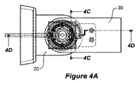
ベースフレーム部分20とケースフレーム部分30との間で動作可能な戻り止め40が配設される。戻り止め40は、図2、図3A、図4A、図4B、図4C、および図4Dに示されている係合位置を有する。この係合位置では、ケースフレーム部分30は、ベースフレーム部分20に対する選択位置で保持される。戻り止めはさらに、ピボット軸12を中心として回転できるようにする図3B、図6A、図6B、および図6Cに示されている係合解除位置を有する。
A detent 40 operable between the
戻り止め40は、第1の組の戻り止め機能部42と、第2の組の戻り止め機能部46とを含む。第1の組の戻り止め機能部42は、ピボット軸12を中心とした回転に対して固定されるが、ケースフレーム部分30およびベースフレーム部分20の両方に対して軸方向に可動である。第2の組の戻り止め機能部46は、ベースフレーム部分20に対する回転に対して固定される。ばね保持具またはばね固定具50およびばね60を含むばねアセンブリは、ケースフレーム部分30をベースフレーム部分20に締結し、かつ第1の組の戻り止め機能部42を第2の組の戻り止め機能部46に締結する。
The detent 40 includes a first set of detent features 42 and a second set of detent features 46. The first set of detent features 42 is fixed against rotation about the
ピボット機構10はさらに、第1の取り付け端部72と第2の浮動端部78とを有する戻り止め部材支持アーム70を含む。第1の取り付け端部72は、共に回転するようにケースフレーム部分30に取り付けられる。第2の浮動端部78は、ケースフレーム部分30に対してピボット軸12に略平行な方向に変位可能である。
The
ばねアセンブリは、互いに離間した第1の保持端部52および第2の保持端部58を有するばね保持具またはばね固定具50と、第1のばね端部62および第2のばね端部68を有する圧縮ばね60とを含む。ばねアセンブリは、図1の分解図と併せて図3Aおよび図3Bの断面図に最も明確に示されているように、ばね固定具50の第1の保持端部52のフランジ53とケースフレーム30との間に配置される。第1のばね端部62は、ばね固定具50の第1の保持端部52に押し付けられ、第2のばね端部68はケースフレーム30に押し付けられる。
The spring assembly includes a spring retainer or
図3Aおよび図3Bに最も明確に示されているように、第2のばね端部68とケースフレーム30との間に、ベアリングワッシャ25が配置される。
As shown most clearly in FIGS. 3A and 3B, a bearing
図1、図3A、図3Bを参照しながら、戻り止め40についてさらに詳細に説明する。 The detent 40 will be described in more detail with reference to FIGS. 1, 3A, and 3B.
図3Aに示されるように、第1の組の戻り止め機能部42は、第2の保持具端部58とベースフレーム20との間で生成された締め付け力によって、第2の組の戻り止め機能部46に押し付けられて第2の組の戻り止め機能部46と係合するのがわかる。この締め付け力は、ばね固定具50の第1の保持端部52のフランジ53を押し付けるばね60によって生成される。この押し上げ力は、管54(図1に示されている)の形態の固定具によって、ばね固定具50の第2の保持具端部58に伝達される。第2の保持具端部58は、上方に押し上がって第1の組の戻り止め機能部42を第2の戻り止め機能部46に押し付ける。
As shown in FIG. 3A, the first set of detent features 42 is coupled to the second set of detents by the clamping force generated between the
図4A、図4B、図4C、および図4Dでは、第1の組の戻り止め機能部42は戻り止め部材支持アーム70に取り付けられているのがわかる(図4Bおよび図4Dに最も明確に示されている)。戻り止め部材支持アーム70は、図1および図4Dに最も明確に示されているように、ねじ32によってねじ受けボス34に取り付けられる。
In FIGS. 4A, 4B, 4C, and 4D, it can be seen that the first set of detent features 42 is attached to the detent member support arm 70 (shown most clearly in FIGS. 4B and 4D). Have been). The detent
戻り止め部材支持アーム70は可撓性であるので、第1の組の戻り止め機能部42を第2の組の戻り止め機能部46から軸方向に離して図3Bに示されている位置に移動させることができる。しかし、戻り止め部材支持アーム70は、ケースフレーム30に対する回転運動に対しては比較的非可撓性である。支持アーム70の段階的軸方向移動は、戻り止め駆動開始の図5A、図5B、および図5Cから、戻り止め解除の相対位置を示した図6A、図6B、および図6dに示されている。
Because the detent
戻り止め40に作用するばねの力は、ケースフレーム部分30をベースフレーム部分20に締結するばねの力に等しい。戻り止め位置と戻り止め解除位置についても同じことが言える。
The spring force acting on the detent 40 is equal to the spring force that fastens the
他の実施形態では、図示されていないが、第1の戻り止め部材42および第2の戻り止め部材46の取り付け場所を変えて、第1の組の戻り止め機能部42がベースフレーム部分20に対して半径方向に移動可能にする支持アーム上に載置され、第2の組の戻り止め機能部46がケースフレーム30に固定されるようにしてもよい。
In other embodiments, although not shown, the first set of
図1に戻ると、移動制限突出部80と移動制限凹部82とが示されている。移動制限突出部80は、ベースフレーム部分20に対して固定され、移動制限凹部82は、ケースフレーム部分30に対して固定される。他の実施形態では、図示されていないが、代替移動制限機能部が使用される場合がある。移動制限機能部は、特定の車両の仕様に従うベースフレーム(ひいては車両)に対するケースフレーム(ひいては、ミラーヘッド)の回転移動を制限してもよい。ばね固定具50は、図1に最も明確に示されているように、スプライン突起部57によってベースフレーム部分20にスプライン結合され、スプライン突起部57は、図4Dの断面図に最も明確に示されている切欠き部59によって受承される。ベースフレーム20に対する回転に対してばね固定具50を固定することによって、図4Dの断面図に最もわかりやすく示されているように、ワイヤリングハーネス90をベースフレーム部分20からばね固定具50に通して、その後、ミラーケースフレーム部分30によって支持されるミラーケースへと案内することができる。図4Dに示されているばね固定具50では、ワイヤリングハーネス90は側方入口からばね固定管54へと入る。代替構造では、ばね固定具50は、ワイヤリングハーネス90をばね固定管54へと真っ直ぐに案内することができる単純な直線状の内部貫通孔を有する。
Returning to FIG. 1, a
図7、図8、図9A、および図9Bには、本発明の代替実施形態が示されている。本発明のこの実施形態の場合、ばね固定具50は、ベースフレーム部分20に対する回転に対してスプライン結合されない。特定の用途において、図7、図8、図9A、および図9Bに示されている実施形態が使用される場合がある。
An alternative embodiment of the present invention is shown in FIGS. 7, 8, 9A, and 9B. For this embodiment of the invention, the
図10には、本発明の代替実施形態が示されている。本発明のこの実施形態の場合、図1〜図9Bに示されている実施形態と比較すると、ばね160が第1の組の戻り止め機能部および第2の組の戻り止め機能部の反対側に位置決めされる。 FIG. 10 shows an alternative embodiment of the present invention. In this embodiment of the present invention, the spring 160 is opposite the first set of detent features and the second set of detent features compared to the embodiment shown in FIGS. Is positioned.
図10および図11は、車両外部バックミラーアセンブリ用ピボット機構10を示した図である。機構10は、車両取り付けベースフレーム21を取り付けるためのベースフレーム部分20を含む。機構10はさらに、ピボット軸12を中心として回転するためにベースフレーム20に取り付けられるケースフレーム部分30を含む。ベースフレーム部分20とケースフレーム30との間で動作可能な戻り止め40も配設される。戻り止め40は、ケースフレーム部分30がベースフレーム部分20に対する選択位置で保持される係合位置を有する。戻り止め40はさらに、ピボット軸12を中心として回転できるようにする係合解除位置を有する。
10 and 11 are views showing a
戻り止め40は、第1の組の戻り止め機能部42と、第2の組の戻り止め機能部46とを含む。 The detent 40 includes a first set of detent features 42 and a second set of detent features 46.
ケースフレーム部分30をベースフレーム部分20に締結し、かつ第1の組の戻り止め機能部42を第2の組の戻り止め機能部46に締結するばね機構も配設される。
A spring mechanism is also provided that fastens the
図10および図11には、ケースフレーム部分30をベースフレーム部分20に締結し、かつ第1の組の戻り止め機能部42を第2の組の戻り止め機能部46に締結するばね機構も示されている。このばね機構もピボット機構10の一部を形成する。
FIGS. 10 and 11 also show a spring mechanism that fastens the
第1の取り付け端部72と第2の浮動端部78とを有する支持アーム70もピボット機構10の一部を形成する。支持アーム70の第2の浮動端部78は、第1の組の戻り止め機能部42を支持する。第1の組の戻り止め機能部42は、支持アーム70に対する回転に対して固定される。しかし、第1の組の戻り止め機能部42は、ケースフレーム部分30に対してピボット軸12に略平行な方向に変位可能である。
A
図10および図11に示されているばね機構は、コイルばね60を含む。本発明の他の実施形態では、コイルばねは使用されない。このような実施形態では、支持アーム70が十分なばね力を付与する機能を果たすことができるので、別のコイルばねは必要でない。
The spring mechanism shown in FIGS. 10 and 11 includes a
上述したように、また図10〜図14Cに示されているように、ピボット機構10は、圧縮ばね50によって生成される第1のばね力と弾性アーム部分75によって生成される第2のばね力の複合効果(総和)によって生じる第1および第2の締め付け力を生成する。それに対して、図15〜図18Dに示されているような他の実施形態では、第1および第2の締め付け力は、弾性アーム部分75のみによって生成されるばね力によって生じる。
As described above and as shown in FIGS. 10-14C, the
図12A〜図12Cでは、第1の組の戻り止め機能部42は、戻り止め部材支持アーム70に取り付けられるのがわかる。戻り止め部材支持アーム70は、図12Bおよび図12Dに最も明確に示されているように、ねじ32によってねじ受けボス34に取り付けられる。
In FIGS. 12A-12C, it can be seen that the first set of detent features 42 is attached to the detent
戻り止め部材支持アームは可撓性であるので、第1の組の戻り止め機能部42を第2の組の戻り止め機能部46から軸方向に離して図14Cに示されている位置に移動させることができる。しかし、戻り止め部材支持アーム70は、ケースフレーム30に対する回転運動に対しては比較的非可撓性である。支持アーム70の段階的軸方向移動は、戻り止め駆動開始の図13A〜図13Cから、戻り止め解除の相対位置を示した図14A〜図14Cに示されている。
Since the detent member support arm is flexible, the first set of detent features 42 is moved axially away from the second set of detent features 46 to the position shown in FIG. 14C. Can be made. However, the detent
ばね機構は、ケースフレーム部分30をベースフレーム部分20に締結する第1の締め付け力と、第1の組の戻り止め機能部42を第2の組の戻り止め機能部46に締結する第2の締め付け力とを生成し、第1の締め付け力と第2の締め付け力の大きさは等しい。図12A〜図12Dに示されている戻り止め位置、さらに図13A〜図13Cに示されている戻り止め開始位置および図14A〜図14Cに示されている戻り止め解除位置についても同じことが言える。しかし、図14A〜図14Cに示されている係合解除位置における第1および第2の締め付け力は、図12A〜図12Dに示されている係合位置における第1および第2の締め付け力より大きい。
The spring mechanism includes a first tightening force for fastening the
図10〜図14Cに示されている実施形態では、ばね機構は、圧縮ばね60とばね固定具50とを含む。ばね固定具50は、互いに離間し、固定部分54によって接続された第1の固定端部52と第2の固定端部58とを有する。第1のばね端部62は、ばね固定具50の第1の固定端部または保持端部52に押し付けられ、第2のばね端部68は、ケースフレーム部分30に押し付けられる。固定部分54は、例えば、図1に示されているように、管としてもよい。あるいは、ばね固定具は、中実としてもよい。固定部分50は、図10および図11に示されているように、ばね60を貫通する。第2の固定端部58は、組み立てるために、固定部分50とは別個の部品である。
In the embodiment shown in FIGS. 10-14C, the spring mechanism includes a
ばね機構は、弾性アーム部分75を含む。弾性アーム部分75は、支持アーム70の第1の取り付け端部72と第2の浮動端部78との間に配置される。
The spring mechanism includes a
支持アーム70と第1の組の戻り止め機能部42は、単一部品で形成され、単一ケース板を形成するようにプレス加工鋼板である。他の実施形態では、図示されていないが、これらの部品は、例えば、戻り止めリングを支持するケース板の骨格部と別個の部品としてもよい。
The
上述の本発明のピボット機構の実施形態それぞれに関して、ベースフレーム部分20とケースフレーム部分30との軸方向相対位置は、係合位置と係合解除位置との間で変化しない。この「ゼロ上昇」により、ミラーアセンブリの部品間の間隙は小さくなり、一定となる。その結果、美的外観が改善され、風切音が低減される。本発明のピボット機構に必要な全体的な垂直方向パッケージ空間は低減される傾向がある。このことは、ミラーアセンブリ設計全体においてさらに利益をもたらす。
For each of the embodiments of the pivot mechanism of the present invention described above, the axial relative position of the
上述の実施形態それぞれにおいて、ばね固定具50が採用されている。ばね固定具は、例えば、図1および図7に示されているように、管状にするのが都合がよい。しかし、主な機能は、ばねアセンブリからの張力を伝達する固定部としての機能を果たすことである。したがって、本発明の他の実施形態では、ばね固定具は、管にする必要はなく、代替実施形態にしてもよい。
In each of the above-described embodiments, the
図15〜図18Dには、本発明のさらに別の実施形態が示されている。本発明のこの実施形態では、コイルばねは必要でない。その代わりに、上述した第1および第2の締め付け力は、支持アーム70の弾性アーム部分75によって生成される。図18A、図18B、および図18Cは、係合状態の支持アーム70と弾性アーム部分75とを示しており、この場合、ケースフレーム部分30は、ベースフレーム部分20に対する選択位置で保持される。
15 to 18D show still another embodiment of the present invention. In this embodiment of the invention, a coil spring is not necessary. Instead, the first and second clamping forces described above are generated by the
図18Dは、点線輪郭で支持アーム70´を示しており、点線輪郭は、アーム70がアセンブリによって下方に変位されない場合のアーム70の位置を表している。弾性アーム部分75は、アーム70によって生成されるばね力に関与する部分である。
FIG. 18D shows the
Claims (12)
ピボット軸を中心として回転するために前記ベースフレーム部分に取り付けられるケースフレーム部分であって、バックミラーを支持するように設計されたケースフレームと一体構造である、またはケースフレームに取り付けられるケースフレーム部分と、
前記ベースフレーム部分と前記ケースフレーム部分との間で動作可能な戻り止めであって、前記ケースフレーム部分が前記ベースフレーム部分に対する選択位置で保持される係合位置と、前記ピボット軸を中心として回転できるようにする係合解除位置とを有し、第1の組の戻り止め機能部と第2の組の戻り止め機能部とを含む戻り止めと、
前記ケースフレーム部分を前記ベースフレーム部分に締結し、かつ前記第1の組の戻り止め機能部を前記第2の戻り止め機能部に締結するばね機構と、
取り付け端部と浮動端部とを有する支持アームであって、前記浮動端部は前記第1の組の戻り止め機能部を支持し、前記第1の組の戻り止め機能部は前記支持アームに対するピボット軸を中心とした回転に対して固定されるが、前記取り付け端部に対しては前記ピボット軸に略平行な方向に変位可能である、支持アームと
を含む、車両外部バックミラーアセンブリ用ピボット機構であって、
前記支持アームの前記取り付け端部は、前記ケースフレーム部分および前記ベースフレーム部分のうちの一方に固定され、前記ケースフレーム部分および前記ベースフレーム部分のうちの一方に対する回転に対して固定され、
前記第2の組の戻り止め機能部は、前記ケースフレーム部分および前記ベースフレーム部分のうちの他方に対する回転に対して固定される、ピボット機構。 A base frame portion that is integral with or attached to the vehicle mounting base frame;
A case frame part that is attached to the base frame part for rotation about a pivot axis and is integral with the case frame designed to support the rearview mirror or attached to the case frame When,
A detent operable between the base frame portion and the case frame portion, wherein the case frame portion is held at a selected position with respect to the base frame portion, and rotates about the pivot shaft. A detent having a disengagement position to allow and including a first set of detent features and a second set of detent features;
A spring mechanism for fastening the case frame portion to the base frame portion and fastening the first set of detent function portions to the second detent function portion;
A support arm having an attachment end and a floating end, the floating end supporting the first set of detent features, wherein the first set of detent features is relative to the support arm; A pivot for a vehicle exterior rearview mirror assembly, including a support arm fixed to rotation about a pivot axis but displaceable in a direction substantially parallel to the pivot axis relative to the mounting end Mechanism,
The attachment end of the support arm is fixed to one of the case frame portion and the base frame portion, fixed to rotation with respect to one of the case frame portion and the base frame portion;
A pivot mechanism in which the second set of detent features is fixed against rotation relative to the other of the case frame portion and the base frame portion.
圧縮ばねと、
互いに離間され、前記ばねを貫通する固定部分によって接続される第1の固定端部と第2の固定端部とを有するばね固定具と
を含む、請求項1に記載のピボット機構。 The spring mechanism is
A compression spring;
The pivot mechanism of claim 1, comprising a spring fixture having a first fixed end and a second fixed end spaced apart from each other and connected by a fixed portion passing through the spring.
Applications Claiming Priority (3)
| Application Number | Priority Date | Filing Date | Title |
|---|---|---|---|
| AU2013901634A AU2013901634A0 (en) | 2013-05-08 | A pivot mechanism for a vehicle external rear view mirror assembly | |
| AU2013901634 | 2013-05-08 | ||
| PCT/IB2014/061261 WO2014181265A1 (en) | 2013-05-08 | 2014-05-07 | A pivot mechanism for a vehicle external rear view mirror assembly |
Related Child Applications (1)
| Application Number | Title | Priority Date | Filing Date |
|---|---|---|---|
| JP2018235962A Division JP6768050B2 (en) | 2013-05-08 | 2018-12-18 | Pivot mechanism for vehicle exterior rearview mirror assembly |
Publications (1)
| Publication Number | Publication Date |
|---|---|
| JP2016521226A true JP2016521226A (en) | 2016-07-21 |
Family
ID=50977004
Family Applications (2)
| Application Number | Title | Priority Date | Filing Date |
|---|---|---|---|
| JP2016512461A Pending JP2016521226A (en) | 2013-05-08 | 2014-05-07 | Pivot mechanism for vehicle exterior rearview mirror assembly |
| JP2018235962A Active JP6768050B2 (en) | 2013-05-08 | 2018-12-18 | Pivot mechanism for vehicle exterior rearview mirror assembly |
Family Applications After (1)
| Application Number | Title | Priority Date | Filing Date |
|---|---|---|---|
| JP2018235962A Active JP6768050B2 (en) | 2013-05-08 | 2018-12-18 | Pivot mechanism for vehicle exterior rearview mirror assembly |
Country Status (5)
| Country | Link |
|---|---|
| US (1) | US9555741B2 (en) |
| EP (1) | EP2994350B1 (en) |
| JP (2) | JP2016521226A (en) |
| CN (1) | CN205292440U (en) |
| WO (1) | WO2014181265A1 (en) |
Families Citing this family (8)
| Publication number | Priority date | Publication date | Assignee | Title |
|---|---|---|---|---|
| WO2016020847A1 (en) * | 2014-08-06 | 2016-02-11 | Smr Patents S.A.R.L. | A pivot assembly for a vehicle external rear vision device and a pivot tie therefore |
| JP6618415B2 (en) * | 2016-04-08 | 2019-12-11 | 株式会社東海理化電機製作所 | Vehicle visual recognition device |
| US10132356B2 (en) * | 2017-02-22 | 2018-11-20 | Mijo Radocaj | Washer with step |
| CN110997411B (en) * | 2017-05-24 | 2023-08-25 | Smr专利有限公司 | Pivot joint system and rearview device with same |
| DE102017129186B4 (en) * | 2017-12-07 | 2021-07-01 | Motherson Innovations Company Limited | Rearview device for a motor vehicle, assembly method therefor and motor vehicle with a rearview device |
| DE102018118268B4 (en) * | 2018-07-27 | 2020-07-09 | Motherson Innovations Company Limited | REVIEW REVIEW WITH LOCKING SYSTEM |
| CN111907424A (en) * | 2020-06-24 | 2020-11-10 | 上海豫兴电子科技有限公司 | Mounting bracket and display |
| US11752942B2 (en) | 2020-08-10 | 2023-09-12 | Ford Global Technologies, Llc | Vehicle body structure mounted side view mirror |
Citations (2)
| Publication number | Priority date | Publication date | Assignee | Title |
|---|---|---|---|---|
| JPH01154942U (en) * | 1988-04-13 | 1989-10-25 | ||
| US6092778A (en) * | 1997-11-04 | 2000-07-25 | Lang-Mekra North America, Llc | Assembly for adjustably mounting vehicle external mirror |
Family Cites Families (26)
| Publication number | Priority date | Publication date | Assignee | Title |
|---|---|---|---|---|
| US1595557A (en) | 1926-03-09 | 1926-08-10 | Mamiya Fusajiro | Folding bicycle handle |
| US3119591A (en) | 1963-06-04 | 1964-01-28 | Delbar Products | Hinged joint support, as for a rear view mirror mounting |
| US3339876A (en) | 1964-06-29 | 1967-09-05 | J W Speaker Corp | Side mount rear view truck mirror |
| US3384334A (en) | 1966-01-20 | 1968-05-21 | Yankee Metal Products Corp | Mirror support |
| US3637186A (en) | 1969-10-16 | 1972-01-25 | Avnet Inc | Detent swivel for truck mirrors and the like |
| US4186905A (en) | 1975-06-09 | 1980-02-05 | Dominion Auto Accessories Limited | Retractable truck mirror |
| DD123169A1 (en) | 1975-12-22 | 1976-12-05 | ||
| DE8627459U1 (en) | 1986-10-15 | 1987-11-19 | Lunke & Sohn Gmbh, 5810 Witten | Door hinge for a vehicle door |
| US4789232A (en) * | 1987-08-14 | 1988-12-06 | Dominion Automotive Industries Inc. | Break-away pivot system for rearview mirrors |
| US5143468A (en) | 1991-04-05 | 1992-09-01 | General Resource Corporation | Articulable joint and support frame for exhaust hose |
| EP0527455B1 (en) | 1991-08-10 | 1996-03-13 | MEKRA Rangau Plastics GmbH & Co KG | Support for the exterior rear view mirror of a utility vehicle |
| GB2281543B (en) | 1993-09-04 | 1996-10-02 | Raydyot Ltd | Mirror mechanisms |
| AU4546299A (en) | 1998-06-03 | 1999-12-20 | Michael Slasinski | Angularly adjustable coupling |
| AUPP853699A0 (en) * | 1999-02-05 | 1999-03-04 | Britax Rainsfords Pty Ltd | A pivot with a detent |
| US6286968B1 (en) * | 1999-09-07 | 2001-09-11 | Lang-Mekra North America, Llc | Mirror mounting assembly with stop feature |
| DE10031330B4 (en) | 2000-07-03 | 2005-10-06 | Donnelly Hohe Gmbh & Co. Kg | Swiveling outside mirror for a motor vehicle |
| JP4153308B2 (en) | 2001-03-26 | 2008-09-24 | シェフェネイカー・ヴィジョン・システムズ・オーストラリア・プロプライアタリー・リミテッド | Vehicle exterior mirror with self-loading pivot and end stop |
| NL1019258C2 (en) * | 2001-10-30 | 2003-05-02 | Iku Holding Montfoort Bv | Fastening construction, in particular for an exterior mirror of a motor vehicle. |
| EP1754090B1 (en) * | 2004-02-18 | 2010-08-04 | SMR Patents S.à.r.l. | Wear-proof détente for folding mirrors |
| US7331552B2 (en) | 2006-01-17 | 2008-02-19 | Infocus Corporation | Hollow pivot |
| US7452088B2 (en) * | 2006-03-07 | 2008-11-18 | Velvac, Incorporated | Mirror with adjustable detent |
| US7887202B1 (en) * | 2007-06-22 | 2011-02-15 | Magna Mirrors Of America, Inc. | Vehicular mirror system with dual detent powerfold assembly |
| US7686274B2 (en) * | 2008-04-17 | 2010-03-30 | Lang-Mekra North America Llc | Pivoting detent joint |
| US8157395B2 (en) * | 2009-05-27 | 2012-04-17 | Murakami Corporation | Folding outer mirror |
| US8336845B1 (en) * | 2011-07-13 | 2012-12-25 | Lang-Mekra North America, Llc | Pivoting detent joint for a vehicle mirror assembly |
| US8720845B2 (en) * | 2011-10-18 | 2014-05-13 | Lang-Mekra North America, Llc | Wear compensator for a pivoting detent joint |
-
2014
- 2014-05-07 EP EP14731365.4A patent/EP2994350B1/en active Active
- 2014-05-07 CN CN201490000654.8U patent/CN205292440U/en not_active Expired - Lifetime
- 2014-05-07 WO PCT/IB2014/061261 patent/WO2014181265A1/en active Application Filing
- 2014-05-07 JP JP2016512461A patent/JP2016521226A/en active Pending
- 2014-05-07 US US14/889,685 patent/US9555741B2/en active Active
-
2018
- 2018-12-18 JP JP2018235962A patent/JP6768050B2/en active Active
Patent Citations (2)
| Publication number | Priority date | Publication date | Assignee | Title |
|---|---|---|---|---|
| JPH01154942U (en) * | 1988-04-13 | 1989-10-25 | ||
| US6092778A (en) * | 1997-11-04 | 2000-07-25 | Lang-Mekra North America, Llc | Assembly for adjustably mounting vehicle external mirror |
Also Published As
| Publication number | Publication date |
|---|---|
| EP2994350A1 (en) | 2016-03-16 |
| US20160114729A1 (en) | 2016-04-28 |
| EP2994350B1 (en) | 2017-09-27 |
| US9555741B2 (en) | 2017-01-31 |
| JP6768050B2 (en) | 2020-10-14 |
| CN205292440U (en) | 2016-06-08 |
| WO2014181265A1 (en) | 2014-11-13 |
| JP2019055779A (en) | 2019-04-11 |
Similar Documents
| Publication | Publication Date | Title |
|---|---|---|
| JP6768050B2 (en) | Pivot mechanism for vehicle exterior rearview mirror assembly | |
| CA2636847A1 (en) | Checker-equipped door hinge device for vehicle | |
| KR101922821B1 (en) | A pivot assembly for a vehicle external rear vision device and a pivot tie therefore | |
| WO2015064344A1 (en) | Steering device | |
| WO2015190301A1 (en) | Steering device | |
| JP2007030527A (en) | Motor-driven position adjustment apparatus for steering wheel | |
| WO2008038621A1 (en) | Device support stand | |
| US11225280B2 (en) | Steering device | |
| JP2008055983A (en) | Adjustable steering apparatus | |
| JP2016055689A (en) | Electric type steering column device | |
| JP2017523936A5 (en) | ||
| JP6621811B2 (en) | Energy absorption module for vehicle steering column assembly | |
| JP4848954B2 (en) | Tilt-type steering device for vehicle | |
| US20060102571A1 (en) | Releasable mounting apparatus | |
| JP2008284973A (en) | Vehicular sunvisor | |
| JP6189212B2 (en) | Retractor unit | |
| JP2006507184A5 (en) | ||
| WO2022269932A1 (en) | Steering column device | |
| JP2009286341A (en) | Steering column device | |
| JP2006282100A (en) | Hinge mechanism of on-vehicle display | |
| JP5811735B2 (en) | Vehicle steering device | |
| JP2010221925A (en) | Energy absorption steering column | |
| JP2006307899A (en) | Electric actuator | |
| JP4858414B2 (en) | Steering device | |
| JP2017124732A (en) | Car back camera mounting structure |
Legal Events
| Date | Code | Title | Description |
|---|---|---|---|
| RD01 | Notification of change of attorney |
Free format text: JAPANESE INTERMEDIATE CODE: A7426 Effective date: 20160628 |
|
| A521 | Request for written amendment filed |
Free format text: JAPANESE INTERMEDIATE CODE: A821 Effective date: 20160629 |
|
| A621 | Written request for application examination |
Free format text: JAPANESE INTERMEDIATE CODE: A621 Effective date: 20170309 |
|
| A131 | Notification of reasons for refusal |
Free format text: JAPANESE INTERMEDIATE CODE: A131 Effective date: 20180126 |
|
| A977 | Report on retrieval |
Free format text: JAPANESE INTERMEDIATE CODE: A971007 Effective date: 20180130 |
|
| A601 | Written request for extension of time |
Free format text: JAPANESE INTERMEDIATE CODE: A601 Effective date: 20180426 |
|
| A521 | Request for written amendment filed |
Free format text: JAPANESE INTERMEDIATE CODE: A523 Effective date: 20180511 |
|
| A02 | Decision of refusal |
Free format text: JAPANESE INTERMEDIATE CODE: A02 Effective date: 20180823 |