JP2016219335A - Led lighting device - Google Patents
Led lighting device Download PDFInfo
- Publication number
- JP2016219335A JP2016219335A JP2015104972A JP2015104972A JP2016219335A JP 2016219335 A JP2016219335 A JP 2016219335A JP 2015104972 A JP2015104972 A JP 2015104972A JP 2015104972 A JP2015104972 A JP 2015104972A JP 2016219335 A JP2016219335 A JP 2016219335A
- Authority
- JP
- Japan
- Prior art keywords
- led
- lighting device
- led lighting
- ceiling
- indoor
- Prior art date
- Legal status (The legal status is an assumption and is not a legal conclusion. Google has not performed a legal analysis and makes no representation as to the accuracy of the status listed.)
- Pending
Links
Images


Landscapes
- Securing Globes, Refractors, Reflectors Or The Like (AREA)
- Arrangement Of Elements, Cooling, Sealing, Or The Like Of Lighting Devices (AREA)
- Non-Portable Lighting Devices Or Systems Thereof (AREA)
- Led Device Packages (AREA)
Abstract
【課題】 天井貫通孔を縮小しつつ、さらなる薄型化を図ることが可能なLED照明装置を提供すること。【解決手段】 各々がLEDチップ21を含む複数のLED発光部2と、複数のLED発光部2に電力を供給する電源部5と、を備え、天井面81に対して固定されるLED照明装置A1であって、複数のLED発光部2は、そのすべてが天井面81よりも室内側に位置し、電源部5の少なくとも一部は、天井面81よりも室外側に位置している。【選択図】 図4PROBLEM TO BE SOLVED: To provide an LED lighting device capable of further reducing the thickness while reducing a ceiling through hole. An LED lighting device comprising a plurality of LED light emitting units 2 each including an LED chip 21 and a power source unit 5 for supplying power to the plurality of LED light emitting units 2 and fixed to a ceiling surface 81. The plurality of LED light emitting units 2 are all located on the indoor side of the ceiling surface 81, and at least a part of the power source unit 5 is positioned on the outdoor side of the ceiling surface 81. [Selection] Figure 4
Description
本発明は、天井面に対して固定されるLED照明装置に関する。 The present invention relates to an LED lighting device fixed to a ceiling surface.
LEDチップを光源として用いた様々なLED照明装置が提案されている。特許文献1には、いわゆるダウンライトとして用いられるLED照明装置が開示されている。このLED照明装置は、複数のLEDチップおよびこれらのLEDチップを点灯させるための電源部を備えている。複数のLEDチップおよび電源部は、天井面よりも室内とは反対側の室外側に配置されている。このような配置を実現するために、天井面には天井貫通孔が設けられている。この天井貫通孔は、複数のLEDチップからの光を通過させる必要がある。このため、天井貫通孔は、平面視においてLED照明装置を略内包する程度の大きさとされる。このような天井貫通孔は、天井が果たすべき断熱機能を低下させるという問題がある。
Various LED illumination devices using LED chips as light sources have been proposed.
特許文献2には、他の方式のLED照明装置が開示されている。当該LED照明装置においては、複数のLEDチップと電源部とが、いずれも天井面よりも室内側に配置されている。このため、天井面には、たとえば給電ケーブルを通過させる程度の天井貫通孔を設ければよい。しかしながら、複数のLEDチップおよび電源部が室内側に位置するため、当該LED照明装置は、室内側に大きく突出するものとならざるを得ない。
本発明は、上記した事情のもとで考え出されたものであって、天井貫通孔を縮小しつつ、さらなる薄型化を図ることが可能なLED照明装置を提供することをその課題とする。 The present invention has been conceived under the circumstances described above, and it is an object of the present invention to provide an LED lighting device capable of further reducing the thickness while reducing the ceiling through hole.
本発明の第1の側面によって提供されるLED照明装置は、各々がLEDチップを含む複数のLED発光部と、前記複数のLED発光部に電力を供給する電源部と、を備え、天井面に対して固定されるLED照明装置であって、前記複数のLED発光部は、そのすべてが前記天井面よりも室内側に位置し、前記電源部の少なくとも一部は、前記天井面よりも室外側に位置していることを特徴としている。 The LED lighting device provided by the first aspect of the present invention includes a plurality of LED light emitting units each including an LED chip, and a power supply unit that supplies power to the plurality of LED light emitting units, and is provided on a ceiling surface. The plurality of LED light emitting units are all located on the indoor side of the ceiling surface, and at least a part of the power supply unit is located on the outdoor side of the ceiling surface. It is characterized by being located in.
本発明の好ましい実施の形態においては、前記複数のLED発光部を収容するケースと、前記LED発光部からの光を透過させる透光カバーと、をさらに備えており、前記ケースのうち前記天井面よりも室内側に位置する部分と前記透光カバーとによって室内部が構成されている。 In a preferred embodiment of the present invention, the apparatus further comprises a case that houses the plurality of LED light emitting units, and a translucent cover that transmits light from the LED light emitting unit, and the ceiling surface of the case. The indoor part is comprised by the part located more indoors, and the said translucent cover.
本発明の好ましい実施の形態においては、前記室内部は、平面視円形状である。 In a preferred embodiment of the present invention, the indoor portion has a circular shape in plan view.
本発明の好ましい実施の形態においては、前記透光カバーは、前記複数のLED発光部からの光を拡散させつつ透過させる。 In preferable embodiment of this invention, the said translucent cover permeate | transmits, diffusing the light from these LED light emission parts.
本発明の好ましい実施の形態においては、前記ケースは、金属からなる。 In a preferred embodiment of the present invention, the case is made of metal.
本発明の好ましい実施の形態においては、前記電源部は、外部の電源供給経路との接続がなされる接続部と、前記接続部にて受けた電力を、前記複数のLED発光部に適した電力に変換するための電力変換部と、を有する。 In a preferred embodiment of the present invention, the power supply unit is connected to an external power supply path, and the power received at the connection unit is suitable for the plurality of LED light emitting units. A power conversion unit for converting to
本発明の好ましい実施の形態においては、前記接続部は、そのすべてが前記天井面よりも室外側に位置している。 In a preferred embodiment of the present invention, all of the connection portions are located on the outdoor side of the ceiling surface.
本発明の好ましい実施の形態においては、前記電力変換部は、そのすべてが前記天井面よりも室外側に位置している。 In a preferred embodiment of the present invention, all of the power conversion unit is located on the outdoor side of the ceiling surface.
本発明の好ましい実施の形態においては、前記電力変換部は、その一部が前記天井面よりも室外側に位置しており、他の一部が前記天井面よりも室内側に位置している。 In a preferred embodiment of the present invention, a part of the power conversion unit is located on the outdoor side of the ceiling surface, and the other part is located on the indoor side of the ceiling surface. .
本発明の好ましい実施の形態においては、前記電源部は、平面視において前記室内部の中心に重なる。 In a preferred embodiment of the present invention, the power supply unit overlaps the center of the indoor portion in plan view.
本発明の好ましい実施の形態においては、前記電源部は、平面視において前記室内部の中心を避けた位置に設けられている。 In preferable embodiment of this invention, the said power supply part is provided in the position which avoided the center of the said indoor part in planar view.
本発明の好ましい実施の形態においては、前記電力変換部は、前記天井面と直角である方向において、前記接続部と前記室内部との間に位置している。 In a preferred embodiment of the present invention, the power conversion unit is located between the connection unit and the indoor unit in a direction perpendicular to the ceiling surface.
本発明の好ましい実施の形態においては、前記接続部は、前記電力変換部に対して、移動が阻止された状態で支持されている。 In preferable embodiment of this invention, the said connection part is supported in the state from which movement was blocked | prevented with respect to the said power conversion part.
本発明の好ましい実施の形態においては、前記接続部は、前記電力変換部に対して、移動可能に支持されている。 In a preferred embodiment of the present invention, the connection portion is supported so as to be movable with respect to the power conversion portion.
本発明の好ましい実施の形態においては、前記接続部は、ばね部材を介して前記電力変換部に支持されている。 In a preferred embodiment of the present invention, the connection part is supported by the power conversion part via a spring member.
本発明の好ましい実施の形態においては、前記接続部および前記電力変換部は、前記天井面よりも室外側に位置しており、且つ平面視において前記室内部を避けた位置に設けられている。 In a preferred embodiment of the present invention, the connection part and the power conversion part are located on the outdoor side of the ceiling surface and are provided at positions avoiding the indoor part in plan view.
本発明の好ましい実施の形態においては、前記室内部と前記電力変換部とを接続する接続ケーブルを更に備える。 In preferable embodiment of this invention, the connecting cable which connects the said indoor part and the said power converter is further provided.
本発明の好ましい実施の形態においては、前記電力変換部および前記接続部は、平面視において互いに異なる位置において前記室内部に対して各別に固定されている。 In a preferred embodiment of the present invention, the power conversion unit and the connection unit are separately fixed to the indoor unit at different positions in plan view.
本発明の好ましい実施の形態においては、前記電力変換部および前記接続部は、前記室内部の同一直径上において、前記室内部の中心を挟んで互いに反対側に配置されている。 In a preferred embodiment of the present invention, the power conversion part and the connection part are arranged on the same diameter of the indoor part and on opposite sides with respect to the center of the indoor part.
本発明の好ましい実施の形態においては、前記室内部を前記天井面に固定するための一対のねじを有する。 In preferable embodiment of this invention, it has a pair of screw | thread for fixing the said indoor part to the said ceiling surface.
本発明の好ましい実施の形態においては、前記一対のねじは、前記室内部の同一直径上において、前記室内部の中心を挟んで互いに反対側に配置されている。 In a preferred embodiment of the present invention, the pair of screws are arranged on opposite sides of the center of the indoor portion on the same diameter of the indoor portion.
本発明の好ましい実施の形態においては、前記天井面には、前記電源部を挿通させるための円形の天井貫通孔が形成されている。 In a preferred embodiment of the present invention, the ceiling surface is formed with a circular ceiling through-hole for allowing the power supply unit to pass therethrough.
本発明の好ましい実施の形態においては、前記天井貫通孔の直径は、前記室内部の直径の10%〜50%である。 In a preferred embodiment of the present invention, the diameter of the ceiling through hole is 10% to 50% of the diameter of the indoor portion.
本発明の好ましい実施の形態においては、前記天井貫通孔の直径は、25mm〜50mmである。 In preferable embodiment of this invention, the diameter of the said ceiling through-hole is 25 mm-50 mm.
本発明の好ましい実施の形態においては、前記室内部の前記天井面からの突出高さは、前記室内部の直径の5%〜25%である。 In preferable embodiment of this invention, the protrusion height from the said ceiling surface of the said indoor part is 5%-25% of the diameter of the said indoor part.
本発明の好ましい実施の形態においては、前記室内部の前記天井面からの突出高さは、10mm〜20mmである。 In preferable embodiment of this invention, the protrusion height from the said ceiling surface of the said indoor part is 10 mm-20 mm.
本発明の好ましい実施の形態においては、前記複数のLED発光部が搭載されたLED基板を備える。 In a preferred embodiment of the present invention, an LED substrate on which the plurality of LED light emitting units are mounted is provided.
本発明の好ましい実施の形態においては、前記LED基板は、前記天井面よりも室内側に位置している。 In preferable embodiment of this invention, the said LED board is located in the room inner side rather than the said ceiling surface.
本発明の好ましい実施の形態においては、前記複数のLED発光部は、前記LED基板に面実装されている。 In a preferred embodiment of the present invention, the plurality of LED light emitting units are surface-mounted on the LED substrate.
本発明の好ましい実施の形態においては、前記複数のLED発光部は、同心円状に配置されている。 In preferable embodiment of this invention, these LED light emission part is arrange | positioned concentrically.
本発明の好ましい実施の形態においては、前記LED基板は、平面視円形状である。 In a preferred embodiment of the present invention, the LED substrate has a circular shape in plan view.
本発明の好ましい実施の形態においては、前記複数のLED発光部は、各々が前記LEDチップ、このLEDチップを覆う透光樹脂、および実装端子を有する。 In a preferred embodiment of the present invention, each of the plurality of LED light emitting units includes the LED chip, a translucent resin that covers the LED chip, and a mounting terminal.
本発明の好ましい実施の形態においては、前記透光樹脂は、前記LEDチップからの光によって励起されることにより前記LEDチップからの光とは異なる波長の光を発する蛍光材料が混入されている。 In a preferred embodiment of the present invention, the translucent resin is mixed with a fluorescent material that emits light having a wavelength different from that of the light from the LED chip when excited by the light from the LED chip.
本発明の第2の側面によって提供されるLED照明装置は、各々がLEDチップを含む複数のLED発光部と、第1の面と第2の面とを有し、前記第1の面上に前記複数のLED発光部が搭載されたLED基板と、前記LED基板の第2の面側に形成され、前記複数のLED発光部に電力を供給する電源部と、を備えたLED照明装置であって、前記LED基板の第2の面と垂直方向からの平面視において、前記電源部は前記LED基板内に包含されており、前記電源部と少なくとも前記複数のLED発光部の一部とが重なっていることを特徴としている。 The LED lighting device provided by the second aspect of the present invention includes a plurality of LED light emitting units each including an LED chip, a first surface, and a second surface, and the first surface is on the first surface. An LED lighting device comprising: an LED substrate on which the plurality of LED light emitting units are mounted; and a power supply unit that is formed on a second surface side of the LED substrate and supplies power to the plurality of LED light emitting units. In the plan view from the direction perpendicular to the second surface of the LED substrate, the power supply unit is included in the LED substrate, and the power supply unit and at least a part of the plurality of LED light emitting units overlap. It is characterized by having.
本発明の好ましい実施の形態においては、前記LED基板を前記第2の面側から保持する主板部と、前記主板部に接続されて前記電源部の少なくとも一部を収容する筒状部と、を備え、前記筒状部は、前記LED基板の第2の面と垂直方向からの平面視において前記電源部を覆い且つ前記基板内に包含されている。 In a preferred embodiment of the present invention, a main plate portion that holds the LED substrate from the second surface side, and a cylindrical portion that is connected to the main plate portion and accommodates at least a part of the power source portion. The cylindrical part covers the power supply part in a plan view from a direction perpendicular to the second surface of the LED board and is included in the board.
本発明の好ましい実施の形態においては、前記LED発光部からの光を拡散させつつ透過させる透光カバーを備える。 In preferable embodiment of this invention, the translucent cover which permeate | transmits while diffusing the light from the said LED light emission part is provided.
本発明によれば、前記電源部の少なくとも一部が前記天井面よりも室外側に配置されており、前記電源部のすべてが前記室内部に含まれる構成とはなっていない。このため、前記室内部が前記天井面から突出する高さを低く抑えることができる。また、前記複数のLED発光部は、そのすべてが前記天井面よりも室内側に配置されている。このため、前記天井の前記天井貫通孔は、前記複数のLED発光部のすべてを平面視において露出させる大きさとする必要がなく、前記電源部の一部を通過させる大きさに縮小することが可能である。したがって、前記天井貫通孔を縮小しつつ、さらなる薄型化を図ることができる。 According to the present invention, at least a part of the power supply unit is arranged outside the ceiling surface, and not all of the power supply unit is included in the indoor unit. For this reason, the height which the said indoor part protrudes from the said ceiling surface can be restrained low. In addition, all of the plurality of LED light emitting units are disposed on the indoor side of the ceiling surface. For this reason, the ceiling through hole of the ceiling does not need to have a size that exposes all of the plurality of LED light emitting units in a plan view, and can be reduced to a size that allows a part of the power supply unit to pass through. It is. Therefore, it is possible to further reduce the thickness while reducing the ceiling through hole.
本発明のその他の特徴および利点は、添付図面を参照して以下に行う詳細な説明によって、より明らかとなろう。 Other features and advantages of the present invention will become more apparent from the detailed description given below with reference to the accompanying drawings.
以下、本発明の好ましい実施の形態につき、図面を参照して具体的に説明する。 Hereinafter, preferred embodiments of the present invention will be specifically described with reference to the drawings.
図1〜図4は、本発明の第1実施形態に基づくLED照明装置を示している。本実施形態のLED照明装置A1は、ケース1、複数のLED発光部2、LED基板27、透光カバー3および電源部5を備えている。LED照明装置A1は、天井8の天井面81に対して固定され、室内を照らす照明装置である。
1 to 4 show an LED lighting device according to a first embodiment of the present invention. The LED lighting device A1 according to the present embodiment includes a
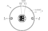
図1は、LED照明装置A1を示す斜視図である。図2は、LED照明装置A1を示す平面図である。図3は、LED照明装置A1を示す底面図である。図4は、図3のIV−IV線に沿う断面図である。 FIG. 1 is a perspective view showing the LED illumination device A1. FIG. 2 is a plan view showing the LED illumination device A1. FIG. 3 is a bottom view showing the LED illumination device A1. 4 is a cross-sectional view taken along line IV-IV in FIG.
なお、以降の説明においては、天井面81に対して直角である方向における室内側を「下」側、室外側を「上」側と称する場合がある。ただし、これは、本発明に係るLED照明装置と鉛直方向との関係を限定するものではない。
In the following description, the indoor side in the direction perpendicular to the
ケース1は、複数のLED発光部2、LED基板27、透光カバー3および電源部5を収容し、且つこれらを支持するものである。ケース1の構成は特に限定されないが、本実施形態においては、ケース1は、金属部11および樹脂部12からなる。
金属部11は、たとえばアルミなどの金属からなる。本実施形態の金属部11は、主板部111および筒状部112を有する。主板部111は、平面視円形状の板状部分であり、天井8の天井面81よりも室内側に位置している。筒状部112は、主板部111に設けられた貫通孔に繋がっている。より具体的には、筒状部112は、前記貫通孔から室外側に向かう方向を中心軸とする円筒部分1121と、この円筒部分1121の室外側端を塞ぐ底板部分1122とを有する。これにより、本実施形態においては、筒状部112は、有底円筒形状である。ただし、筒状部112は、底板部分1122を有さない構成でもよく、たとえば角筒形状であってもよい。また、筒状部112は、天井8との関係において、天井8の天井面81よりも室内側に位置する第1部112a、天井8の天井面81と天井裏面82との間に位置する第2部112b、および天井裏面82よりも室外側に位置する第3部112cを有している。なお、図4においては、第1部112a、第2部112bおよび第3部112cのそれぞれを囲む点線を記載している。隣り合う点線の境界を若干離間させているが、これは理解の便宜であり、第1部112a、第2部112bおよび第3部112cは、天井面81および天井裏面82との相対関係で区画されるものである。この点は、以降の図面においても同様である。
The
樹脂部12は、金属部11の主板部111を囲んでおり、平面視円環形状である。樹脂部12は、たとえばプラスチックなどの樹脂からなる。
The
また、本実施形態においては、ケース1の金属部11の主板部111と天井8の天井面81との隙間に、断熱部材71が設けられている。断熱部材71は、たとえばグラスウールに代表される繊維系断熱材料や発泡スチロールに代表される多孔質系断熱材料からなる。このような構成により、天井8を介した室内外の温度差に起因する熱の移動を抑制することができる。天井8に天井貫通孔83を設けることは、このような熱移動の抑制には不利であるが、断熱部材71を採用することにより、過大な室温変化を回避することができる。なお、LED照明装置A1において、断熱部材71を設けない構成を採用してもよく、これは、以降に説明する実施形態においても同様である。
In the present embodiment, the
複数のLED発光部2は、LED照明装置A1の光源をなす構成要素である。図5は、本実施形態のLED発光部2を示す拡大断面図である。LED発光部2は、LEDチップ21、一対のリード22、ケース23および透光樹脂24を具備している。
Several LED
LEDチップ21は、たとえばGaN系半導体からなり、たとえば青色光を発する。透光樹脂24は、LEDチップ21を覆っており、たとえば透明樹脂に蛍光材料が混入された材質からなる。この蛍光材料は、LEDチップ21からの青色光によって励起されることにより黄色光を発する。この蛍光材料の種類および濃度は、LEDチップ21からの青色光とこの蛍光材料からの黄色光とが混色することにより昼白色などの白色を呈するように調整されている。
The
一対のリード22は、LEDチップ21を支持し、かつLEDチップ21への導通経路となるものであり、たとえばCu合金などからなる。一対のリード22の図中下面が、本発明で言う実装端子を構成する。LED発光部2は、LED基板27に面実装によって搭載されている。
The pair of
ケース23は、たとえば白色樹脂からなり、LEDチップ21を囲む枠状である。ケース23の内側面は、LEDチップ21からの光を反射することによりこの光を出射させるリフレクタとして機能している。
The
LED基板27は、複数のLED発光部2が搭載された基板である。このようなLED基板27の一例としては、ガラスエポキシ樹脂からなる基材と、この基材上に形成された配線パターンとを有する構成が挙げられる。図4に示すように、LED基板27は、天井面81よりも室内側に位置している。LED基板27は、第1の面271および第2の面272を有している。第1の面271は、第2の面272に対して室内側に位置する。複数のLED発光部2は、LED基板27の第1の面271に面実装されている。複数のLED発光部2は、平面視において同心円状に配置されている。LED基板27は、平面視円形状である。LED基板27は、ケース1の金属部11の主板部111の周端に取り付けられており、第2の面272側から主板部111に保持されている。また、LED基板27は、平面視において主板部111と重なっており、主板部111と同じか若干小さい大きさである。本実施形態においては、平面視においてLED基板27の中心と金属部11の筒状部112の中心とが略一致している。また、平面視において、LED基板27の面積は天井貫通孔83の面積よりも大であり、LED基板27の径は天井8の天井貫通孔83の径よりも大であり、LED基板27の面積は、電力変換部52の面積よりも大である。これにより、給電ケーブル89とLED基板27とを結ぶ天井貫通孔83を小さくしつつも、LED発光部2の配置面積を確保することが可能であり、より高い輝度を実現できる。複数のLED発光部2およびLED基板27は、天井8の天井面81よりも室内側に位置している。なお、LED基板27は、平面視円形状に限定されず、たとえば平面視矩形状であってもよい。また、天井貫通孔83は、平面視円形状に限定されず、たとえば平面視矩形状であってもよい。
The
透光カバー3は、複数のLED発光部2からの光を透過させるものであり、平面視において複数のLED発光部2を覆っている。また、本実施形態においては、透光カバー3は、複数のLED発光部2からの光を拡散させつつ透過させる。このような透光カバー3としては、たとえば半透明な乳白色の樹脂からなるものが一例として挙げられる。透光カバー3は、平面視円形状であり、ケース1の樹脂部12によって支持されている。
The
ここで、LED照明装置A1の外観のうち天井面81よりも室内側においてLED照明装置A1の外観を構成する部位を室内部4と称する。室内部4は、ケース1のうち天井面81よりも室内側に位置する部分と透光カバー3とを含む。本実施形態においては、ケース1のうち室内部4を構成する部位に相当するものは、樹脂部12である。ただし、金属部11の一部が樹脂部12から露出することにより、金属部11の一部が室内部4を構成してもよい。本実施形態においては、室内部4は、平面視円形状である。
Here, the part which comprises the external appearance of LED lighting apparatus A1 in the indoor side rather than the
電源部5は、複数のLED発光部2に電力を供給するためのものである。本実施形態においては、電源部5は、接続部51および電力変換部52を有する。電源部5は、LED基板27の第2の面272側に形成されている。また、電源部5は、LED基板27の第2の面272と垂直方向からの平面視において、LED基板27内に包含されている。また、電源部5は、平面視において、金属部11の筒状部112によって覆われている。
The
接続部51は、外部の電源供給経路である給電ケーブル89との接続がなされる部位である。本実施形態においては、接続部51は、支持部材511およびコネクタ512を有する。コネクタ512は、給電ケーブル89と直接的に接続される部位であり、たとえば汎用のコネクタが用いられる。支持部材511は、コネクタ512を支持する部位である。
The
本実施形態においては、支持部材511は、ケース1の金属部11の筒状部112の底板部分1122に対して室外側(上側)に取り付けられており、筒状部112の直上に位置している。また、コネクタ512には、給電ケーブル89が直上から差し込まれる構成となっている。
In the present embodiment, the
電力変換部52は、接続部51にて受けた電力を、複数のLED発光部2に適した電力に変換するためのものであり、たとえば、入力された交流電力を、定電流の直流電力に変換する。図6は、電源部5を示す右側面図であり、図7は、電源部5を示す平面図である。なお、図6は、図7におけるVI線方向からみた図である。電力変換部52の仕様の一例を挙げると、定格入力電圧が100V程度、定格出力電流が100mA程度、定格出力電圧が27V〜47Vである。
The
本実施形態の電力変換部52は、電源基板521および複数の電子素子522を有する。
The
電源基板521は、複数の電子素子522が実装される基板である。本実施形態においては、電源基板521は、平面視円形状とされている。電源基板521の直径は、たとえば25mm〜30mmである。
The
複数の電子素子522は、電力変換部52が果たすべき電力変換機能を実現する電気回路を構成する素子である。本実施形態においては、複数の電子素子522は、コンデンサ523、ダイオード524、ヒューズ525、IC526、コイル527、チップ抵抗528、トランス529およびバリスタ530を含む。また、複数の電子素子522は、整流ダイオードブリッジ(図示略)を含む。
The plurality of
コンデンサ523は、容量がたとえば6.8μFおよび33μF程度である。ダイオード524は、ファストリカバリーダイオードであり、直流逆方向電圧が400V程度、平均整流電流が1A程度である。ヒューズ525は、容量が1.5A程度である。IC526は、MOSFETが内蔵されており、電力変換制御を行う。コイル527は、容量が1.5mH程度とされた面実装コイルである。チップ抵抗528は、抵抗値が75kΩ〜510kΩ程度である。トランス529は、いわゆる変圧機能を果たす素子である。バリスタ530は、いわゆる非直線性抵抗素子であり、耐圧が470V程度である。
また、電力変換部52は、2つの入力端子531および2つの出力端子532を有している。2つの入力端子531は、外部からの交流電力が入力される端子である。2つの出力端子532は、LED基板27を介して複数のLED発光部2へと直流電力が出力される端子である。
The
図4に示すように、電源基板521および複数の電子素子522は、ケース1の金属部11の筒状部112に収容されている。本実施形態においては、接続部51は、その全てが天井8の天井面81よりも室外側に位置している。電力変換部52は、その全てが天井8の天井面81よりも室外側に位置している。また、電力変換部52の一部は、天井8の天井裏面82よりも室外側に位置している。図3に示すように、電源部5は、平面視において室内部4の中心に重なる位置に設けられている。本実施形態においては、接続部51と電力変換部52とは、接続ケーブル571を介して接続されている。また、電力変換部52とLED基板27とは、接続ケーブル572を介して接続されている。
As shown in FIG. 4, the
天井8には、天井貫通孔83が設けられている。天井貫通孔83は、ケース1の金属部11の筒状部112、すなわち電源部5を天井面81よりも室外側に位置させるためのものである。本実施形態においては、天井貫通孔83は、平面視円形状である。
The
一対のねじ6は、LED照明装置A1を天井面81に固定するためのものである。より具体的には、一対のねじ6は、ケース1の金属部11の主板部111を天井面81に対して固定することにより、LED照明装置A1を天井面81に固定している。一対のねじ6は、室内部4の同一直径上において、室内部4の中心を挟んで互いに反対側に配置されている。
The pair of
LED照明装置A1の主要寸法の好ましい例を挙げる。室内部4の直径D1は、70mm〜300mmである。天井8の天井貫通孔83の直径D2は、25mm〜50mmである。直径D2は、直径D1の10%〜50%である。また室内部4の天井面81からの高さHは、10mm〜20mmである。高さHは、直径D1の5%〜25%である。なお、これらの寸法および比率が好ましい点は、後述する変形例および実施形態においても同様である。
The preferable example of the main dimension of LED lighting apparatus A1 is given. A diameter D1 of the
次に、LED照明装置A1の作用について説明する。 Next, the operation of the LED lighting device A1 will be described.
本実施形態によれば、電源部5の少なくとも一部が天井面81よりも室外側に配置されており、電源部5のすべてが室内部4に含まれる構成とはなっていない。このため、室内部4が天井面81から突出する高さHを低く抑えることができる。また、複数のLED発光部2は、そのすべてが天井面81よりも室内側に配置されている。このため、天井8の天井貫通孔83は、複数のLED発光部2のすべてを平面視において露出させる大きさとする必要がなく、電源部5の一部を通過させる大きさに縮小することが可能である。したがって、天井貫通孔83を縮小しつつ、室内部4のさらなる薄型化を図ることができる。
According to the present embodiment, at least a part of the
接続部51および電力変換部52のすべてが、天井面81よりも室外側に位置することにより、室内部4には、電源部5が全く含まれていない。これは、室内部4の薄型化に好ましい。
Since all of
透光カバー3が、複数のLED発光部2からの光を拡散させることにより、透光カバー3と複数のLED発光部2との距離を縮小しつつ、複数のLED発光部2の各々が外観に明瞭に現れることを抑制することができる。
The
電源部5が、平面視において室内部4の中心と重なる位置に設けられている。これにより、天井8に天井貫通孔83を開口する際に、LED照明装置A1を取り付けようとする中心位置に天井貫通孔83を設ければよい。これは、工事作業の簡便化に好ましい。
The
接続部51と電力変換部52とが上下に位置する関係であることにより、天井貫通孔83をより縮小することができる。
Since the
一対のねじ6は、電源部5を挟んで互いに反対側に位置している。これにより、一対のねじ6と電源部5とが干渉することを回避しつつ、LED照明装置A1を天井面81により確実に固定することができる。
The pair of
天井8の天井貫通孔83の直径D2が、25mm〜50mmであるとともに、直径D2が、直径D1の10%〜50%であることにより、天井貫通孔83を設けることによる断熱機能の低下を抑制するとともに、室内を十分に照らすことができる大きさに室内部4を設定することができる。また室内部4の天井面81からの高さHが、10mm〜20mmであるとともに、直径D1の5%〜25%であることにより、いわゆるダウンライトと同様の外観を達成することができる。
The diameter D2 of the ceiling through-
図8〜図23は、本発明の変形例および他の実施形態を示している。なお、これらの図において、上記実施形態と同一または類似の要素には、上記実施形態と同一の符号を付しており、これ以降の説明を適宜省略する。 FIGS. 8-23 has shown the modification and other embodiment of this invention. In these drawings, elements that are the same as or similar to those in the above embodiment are denoted by the same reference numerals as in the above embodiment, and the subsequent description is omitted as appropriate.
図8は、LED照明装置A1の変形例を示している。本変形例のLED照明装置A1は、ケース1、複数のLED発光部2、LED基板27、透光カバー3および電源部5を備えている。本変形例においては、電源部5の一部が天井面81よりも室外側に位置しており、他の一部が天井面81よりも室内側に位置している。より具体的には、接続部51は、その全体が天井面81よりも室外側に位置しており、さらに天井裏面82よりも室外側に位置している。一方、電力変換部52は、天井貫通孔83を介して、室内外に亘って配置されている。より具体的には、電源部5の電力変換部52の電源基板521が天井面81よりも室内側に位置している。また、電力変換部52の電子素子522の一部は、天井裏面82よりも室外側に位置している。このような変形例によっても、天井貫通孔83を縮小しつつ、室内部4のさらなる薄型化を図ることができる。このような変形例は、以下に述べる実施形態にも適宜採用することができる。
FIG. 8 shows a modification of the LED lighting device A1. The LED lighting device A1 according to this modification includes a
図9〜図11は、本発明の第2実施形態に基づくLED照明装置を示している。本実施形態のLED照明装置A2は、ケース1、複数のLED発光部2、LED基板27、透光カバー3および電源部5を備えている。LED照明装置A2は、電源部5の構成が上述した実施形態と異なっている。
9 to 11 show an LED lighting device according to a second embodiment of the present invention. The LED illumination device A2 according to the present embodiment includes a
図9は、LED照明装置A2を示す平面図である。図10は、LED照明装置A2を示す底面図である。図11は、図10のXI−XI線に沿う断面図である。 FIG. 9 is a plan view showing the LED illumination device A2. FIG. 10 is a bottom view showing the LED lighting device A2. 11 is a cross-sectional view taken along line XI-XI in FIG.
本実施形態の電源部5は、ばね部材55を有している。ばね部材55は、電力変換部52(金属部11の筒状部112)に対して接続部51を移動可能に固定するためのものである。本実施形態においては、ばね部材55は、屈曲形状に折り曲げ加工が施された板ばねからなる。ばね部材55を有することにより、図11に示すように、接続部51は、電力変換部52に対して回動可能とされている。このような実施形態によっても、天井貫通孔83を縮小しつつ、室内部4のさらなる薄型化を図ることができる。また、電力変換部52に接続された給電ケーブル89が延びる方向を水平方向や鉛直方向に任意に設定することができる。
The
図12〜図14は、本発明の第3実施形態に基づくLED照明装置を示している。本実施形態のLED照明装置A3は、ケース1、複数のLED発光部2、LED基板27、透光カバー3および電源部5を備えている。LED照明装置A3は、電源部5の構成が上述した実施形態と異なっている。
FIGS. 12-14 has shown the LED lighting apparatus based on 3rd Embodiment of this invention. The LED lighting device A3 according to the present embodiment includes a
図12は、LED照明装置A3を示す平面図である。図13は、LED照明装置A3を示す底面図である。図14は、図13のXIV−XIV線に沿う断面図である。 FIG. 12 is a plan view showing the LED illumination device A3. FIG. 13 is a bottom view showing the LED lighting device A3. 14 is a cross-sectional view taken along line XIV-XIV in FIG.
本実施形態においては、電源部5が、平面視において室内部4の中心を避けた位置に設けられている。また、一対のねじ6は、電源部5に対して周方向において90度ずれた方位にそれぞれ配置されている。このような実施形態によっても、天井貫通孔83を縮小しつつ、室内部4のさらなる薄型化を図ることができる。また、電源部5が、平面視において室内部4の中心を避けて配置されていることにより、天井8の梁などが室内部4の中心を通る配置とすることが可能である。これは、LED照明装置A3をより安定して支持するのに適している.また、一対のねじ6を固定すべき天井8の梁などと電源部5との干渉を回避することができる。
In the present embodiment, the
図15および図16は、本発明の第4実施形態に基づくLED照明装置を示している。本実施形態のLED照明装置A4は、ケース1、複数のLED発光部2、LED基板27、透光カバー3および電源部5を備えている。LED照明装置A4は、電源部5の構成が上述した実施形態と異なっている。
15 and 16 show an LED lighting device according to a fourth embodiment of the present invention. The LED illumination device A4 of the present embodiment includes a
図15は、LED照明装置A4を示す底面図である。図16は、図15のXVI−XVI線に沿う断面図である。 FIG. 15 is a bottom view showing the LED illumination device A4. 16 is a cross-sectional view taken along line XVI-XVI in FIG.
本実施形態においては、電源部5は、平面視において室内部4の中心を避けた位置に設けられている。また、電源部5は、接続部51と電力変換部52との間に介在するばね部材55を有している。このような実施形態によっても、天井貫通孔83を縮小しつつ、室内部4のさらなる薄型化を図ることができる。
In the present embodiment, the
図17および図18は、本発明の第5実施形態に基づくLED照明装置を示している。本実施形態のLED照明装置A5は、ケース1、複数のLED発光部2、LED基板27、透光カバー3および電源部5を備えている。LED照明装置A5は、電源部5の構成が上述した実施形態と異なっている。
17 and 18 show an LED lighting device according to a fifth embodiment of the present invention. The LED illumination device A5 of the present embodiment includes a
図17は、LED照明装置A5を示す底面図である。図18は、図17のXVIII−XVIII線に沿う断面図である。 FIG. 17 is a bottom view showing the LED illumination device A5. 18 is a cross-sectional view taken along line XVIII-XVIII in FIG.
本実施形態においては、電源部5は、平面視において室内部4全体を避けた位置に設けられている。電源部5の電力変換部52とLED基板27とは、接続ケーブル56によって接続されている。また、接続部51と電力変換部52とは、水平方向に並べられている。このような実施形態によっても、天井貫通孔83を縮小しつつ、室内部4のさらなる薄型化を図ることができる。また、電源部5を一対のねじ6から大きく離間させることが可能である。これにより、天井8の梁84に一対のねじ6を取り付ける際に、電源部5と梁84とが干渉することを確実に防止することができる。
In the present embodiment, the
図19および図20は、本発明の第6実施形態に基づくLED照明装置を示している。本実施形態のLED照明装置A6は、ケース1、複数のLED発光部2、LED基板27、透光カバー3および電源部5を備えている。LED照明装置A6は、電源部5の構成が上述した実施形態と異なっている。
19 and 20 show an LED lighting device according to a sixth embodiment of the present invention. The LED illumination device A6 according to this embodiment includes a
図19は、LED照明装置A6を示す底面図である。図20は、図19のXX−XX線に沿う断面図である。 FIG. 19 is a bottom view showing the LED illumination device A6. 20 is a cross-sectional view taken along line XX-XX in FIG.
本実施形態においては、接続部51と電力変換部52とは、平面視において室内部4の中心を挟んで互いに反対側に配置されている。また、これに対応して、天井8には、2つの天井貫通孔83が設けられている。一方の天井貫通孔83には、接続部51が挿通されており、他方の天井貫通孔83には、電力変換部52が挿通されている。このような実施形態によっても、天井貫通孔83を縮小しつつ、室内部4のさらなる薄型化を図ることができる。また、接続部51および電力変換部52が梁84と干渉することを回避することができる。
In this embodiment, the
図21〜図23は、本発明の第7実施形態に基づくLED照明装置を示している。本実施形態のLED照明装置A7は、ケース1、複数のLED発光部2、LED基板27、透光カバー3および電源部5を備えている。LED照明装置A7は、天井8への固定機構が上述した実施形態と異なっている。
21 to 23 show an LED lighting device according to a seventh embodiment of the present invention. The LED illumination device A7 of the present embodiment includes a
図21は、LED照明装置A6を示す底面図である。図22は、図21のXXII−XXII線に沿う断面図である。図22は、図21のXXII−XXII線に沿う断面図である。図23は、図21のXXIII−XXIII線に沿う断面図である。 FIG. 21 is a bottom view showing the LED lighting device A6. 22 is a cross-sectional view taken along line XXII-XXII in FIG. 22 is a cross-sectional view taken along line XXII-XXII in FIG. 23 is a cross-sectional view taken along line XXIII-XXIII in FIG.
本実施形態においては、LED照明装置A7は、2つの固定ばね61によって天井8に固定されている。2つの固定ばね61は、ケース1の金属部11の筒状部112に固定されており、図21に示すように、筒状部112の径方向外方両側に延出している。固定ばね61は、たとえばばね鋼からなる帯板を折り曲げ加工することによって形成されている。図22において、想像線で示す2つの固定ばね61は、弾性力を発揮していない自然状態を示している。LED照明装置A7を天井8に取り付ける際には、2つの固定ばね61を変形させ、電源部5および金属部11の筒状部112に添わせる。そして、電源部5および筒状部112と2つの固定ばね61とを天井8の天井貫通孔83に挿通させる。2つの固定ばね61を図22に示す状態まで挿入すると、2つの固定ばね61は、互いに離間するように変形する。図22において実線で示す2つの固定ばね61は、挿入が完了した状態を示している。広がった形態となった2つの固定ばね61は、LED照明装置A7が天井8に対して室内側(下側)に移動することを阻止する機能を果たす。これにより、LED照明装置A7が天井8に対して固定される。
In the present embodiment, the LED lighting device A <b> 7 is fixed to the
本発明に係るLED照明装置は、上述した実施形態に限定されるものではない。本発明に係るLED照明装置の各部の具体的な構成は、種々に設計変更自在である。 The LED lighting device according to the present invention is not limited to the embodiment described above. The specific configuration of each part of the LED lighting device according to the present invention can be varied in design in various ways.
A1〜A7 LED照明装置
D1,D2 直径
H 高さ
1 ケース
11 金属部
111 主板部
112 筒状部
112a 第1部
112b 第2部
112c 第3部
1121 円筒部分
1122 底板部分
12 樹脂部
2 LED発光部
21 LEDチップ
22 リード
23 ケース
24 透光樹脂
27 LED基板
271 第1の面
272 第2の面
3 透光カバー
4 室内部
5 電源部
51 接続部
511 支持部材
512 コネクタ
52 電力変換部
521 電源基板
522 電子素子
523 コンデンサ
524 ダイオード
525 ヒューズ
526 IC
527 コイル
528 チップ抵抗
529 トランス
530 バリスタ
531 入力端子
532 出力端子
55 ばね部材
56 接続ケーブル
571 接続ケーブル
572 接続ケーブル
6 ねじ
61 固定ばね
71 断熱部材
8 天井
81 天井面
82 天井裏面
83 天井貫通孔
84 梁
89 給電ケーブル
A1 to A7 LED lighting devices D1, D2
527
Claims (36)
前記複数のLED発光部に電力を供給する電源部と、を備え、
天井面に対して固定されるLED照明装置であって、
前記複数のLED発光部は、そのすべてが前記天井面よりも室内側に位置し、
前記電源部の少なくとも一部は、前記天井面よりも室外側に位置していることを特徴とする、LED照明装置。 A plurality of LED light emitting sections each including an LED chip;
A power supply unit that supplies power to the plurality of LED light emitting units,
An LED lighting device fixed to a ceiling surface,
All of the plurality of LED light emitting units are located on the indoor side of the ceiling surface,
At least a part of the power supply unit is located on the outdoor side of the ceiling surface.
前記LED発光部からの光を透過させる透光カバーと、をさらに備えており、
前記ケースのうち前記天井面よりも室内側に位置する部分と前記透光カバーとによって室内部が構成されている、請求項1に記載のLED照明装置。 A case for housing the plurality of LED light emitting units;
A light-transmitting cover that transmits light from the LED light-emitting unit, and
The LED lighting device according to claim 1, wherein an indoor portion is configured by a portion of the case that is located on the indoor side of the ceiling surface and the translucent cover.
前記接続部にて受けた電力を、前記複数のLED発光部に適した電力に変換するための電力変換部と、を有する、請求項3ないし5のいずれかに記載のLED照明装置。 The power supply unit is connected to an external power supply path; and
The LED lighting device according to claim 3, further comprising: a power conversion unit configured to convert electric power received at the connection unit into electric power suitable for the plurality of LED light emitting units.
第1の面と第2の面とを有し、前記第1の面上に前記複数のLED発光部が搭載されたLED基板と、
前記LED基板の第2の面側に形成され、前記複数のLED発光部に電力を供給する電源部と、を備えたLED照明装置であって、
前記LED基板の第2の面と垂直方向からの平面視において、前記電源部は前記LED基板内に包含されており、前記電源部と少なくとも前記複数のLED発光部の一部とが重なっていることを特徴とするLED照明装置。 A plurality of LED light emitting sections each including an LED chip;
An LED substrate having a first surface and a second surface, wherein the plurality of LED light emitting units are mounted on the first surface;
A power supply unit that is formed on the second surface side of the LED substrate and supplies power to the plurality of LED light emitting units, and an LED lighting device comprising:
In a plan view from a direction perpendicular to the second surface of the LED substrate, the power supply unit is included in the LED substrate, and the power supply unit and at least a part of the plurality of LED light emitting units overlap. LED lighting device characterized by the above.
前記主板部に接続されて前記電源部の少なくとも一部を収容する筒状部と、
を備え、
前記筒状部は、前記LED基板の第2の面と垂直方向からの平面視において前記電源部を覆い且つ前記基板内に包含されている、請求項34に記載のLED照明装置。 A main plate portion for holding the LED substrate from the second surface side;
A cylindrical part connected to the main plate part and accommodating at least a part of the power supply part;
With
The LED lighting device according to claim 34, wherein the cylindrical portion covers the power supply unit and is included in the substrate in a plan view from a direction perpendicular to the second surface of the LED substrate.
Priority Applications (1)
| Application Number | Priority Date | Filing Date | Title |
|---|---|---|---|
| JP2015104972A JP2016219335A (en) | 2015-05-22 | 2015-05-22 | Led lighting device |
Applications Claiming Priority (1)
| Application Number | Priority Date | Filing Date | Title |
|---|---|---|---|
| JP2015104972A JP2016219335A (en) | 2015-05-22 | 2015-05-22 | Led lighting device |
Publications (1)
| Publication Number | Publication Date |
|---|---|
| JP2016219335A true JP2016219335A (en) | 2016-12-22 |
Family
ID=57581437
Family Applications (1)
| Application Number | Title | Priority Date | Filing Date |
|---|---|---|---|
| JP2015104972A Pending JP2016219335A (en) | 2015-05-22 | 2015-05-22 | Led lighting device |
Country Status (1)
| Country | Link |
|---|---|
| JP (1) | JP2016219335A (en) |
Cited By (33)
| Publication number | Priority date | Publication date | Assignee | Title |
|---|---|---|---|---|
| JP2019091568A (en) * | 2017-11-13 | 2019-06-13 | パナソニックIpマネジメント株式会社 | Lighting fixture and luminaire |
| US10663127B2 (en) | 2017-06-22 | 2020-05-26 | DMF, Inc. | Thin profile surface mount lighting apparatus |
| US10753558B2 (en) | 2013-07-05 | 2020-08-25 | DMF, Inc. | Lighting apparatus and methods |
| US10816148B2 (en) | 2013-07-05 | 2020-10-27 | DMF, Inc. | Recessed lighting systems |
| USD901398S1 (en) | 2019-01-29 | 2020-11-10 | DMF, Inc. | Plastic deep electrical junction box |
| USD902871S1 (en) | 2018-06-12 | 2020-11-24 | DMF, Inc. | Plastic deep electrical junction box |
| USD905327S1 (en) | 2018-05-17 | 2020-12-15 | DMF, Inc. | Light fixture |
| USD907284S1 (en) | 2014-02-18 | 2021-01-05 | DMF, Inc. | Module applied to a lighting assembly |
| US10975570B2 (en) | 2017-11-28 | 2021-04-13 | DMF, Inc. | Adjustable hanger bar assembly |
| US11022259B2 (en) | 2015-05-29 | 2021-06-01 | DMF, Inc. | Lighting module with separated light source and power supply circuit board |
| US11060705B1 (en) | 2013-07-05 | 2021-07-13 | DMF, Inc. | Compact lighting apparatus with AC to DC converter and integrated electrical connector |
| US11067231B2 (en) | 2017-08-28 | 2021-07-20 | DMF, Inc. | Alternate junction box and arrangement for lighting apparatus |
| JPWO2020027327A1 (en) * | 2018-08-03 | 2021-08-19 | 日亜化学工業株式会社 | How to build a building and how to install lightweight large lighting fixtures in a building |
| US11118768B2 (en) | 2015-04-22 | 2021-09-14 | DMF, Inc. | Outer casing for a recessed lighting fixture |
| US11231154B2 (en) | 2018-10-02 | 2022-01-25 | Ver Lighting Llc | Bar hanger assembly with mating telescoping bars |
| US11242983B2 (en) | 2015-11-16 | 2022-02-08 | DMF, Inc. | Casing for lighting assembly |
| US11255497B2 (en) | 2013-07-05 | 2022-02-22 | DMF, Inc. | Adjustable electrical apparatus with hangar bars for installation in a building |
| USD944212S1 (en) | 2015-10-05 | 2022-02-22 | DMF, Inc. | Electrical junction box |
| USD945054S1 (en) | 2017-06-22 | 2022-03-01 | DMF, Inc. | Light fixture |
| US11274821B2 (en) | 2019-09-12 | 2022-03-15 | DMF, Inc. | Lighting module with keyed heat sink coupled to thermally conductive trim |
| US11306903B2 (en) | 2020-07-17 | 2022-04-19 | DMF, Inc. | Polymer housing for a lighting system and methods for using same |
| US11391442B2 (en) | 2018-06-11 | 2022-07-19 | DMF, Inc. | Polymer housing for a recessed lighting system and methods for using same |
| US11435064B1 (en) | 2013-07-05 | 2022-09-06 | DMF, Inc. | Integrated lighting module |
| US11448384B2 (en) | 2017-12-27 | 2022-09-20 | DMF, Inc. | Methods and apparatus for adjusting a luminaire |
| USD966877S1 (en) | 2019-03-14 | 2022-10-18 | Ver Lighting Llc | Hanger bar for a hanger bar assembly |
| USD970081S1 (en) | 2018-05-24 | 2022-11-15 | DMF, Inc. | Light fixture |
| US11585517B2 (en) | 2020-07-23 | 2023-02-21 | DMF, Inc. | Lighting module having field-replaceable optics, improved cooling, and tool-less mounting features |
| USD990030S1 (en) | 2020-07-17 | 2023-06-20 | DMF, Inc. | Housing for a lighting system |
| USD1012864S1 (en) | 2019-01-29 | 2024-01-30 | DMF, Inc. | Portion of a plastic deep electrical junction box |
| US12203631B2 (en) | 2020-07-16 | 2025-01-21 | DMF, Inc. | Round metal housing for a lighting system |
| US12297986B2 (en) | 2020-07-17 | 2025-05-13 | DMF, Inc. | Bar hanger assembly with crossmembers and housing assemblies using same |
| JP2025076980A (en) * | 2023-11-02 | 2025-05-16 | 株式会社Yamagiwa | Lighting fixtures |
| US12546465B2 (en) | 2022-03-14 | 2026-02-10 | DMF, Inc. | Lighting module with keyed heat sink coupled to thermally conductive trim |
-
2015
- 2015-05-22 JP JP2015104972A patent/JP2016219335A/en active Pending
Cited By (53)
| Publication number | Priority date | Publication date | Assignee | Title |
|---|---|---|---|---|
| US10982829B2 (en) | 2013-07-05 | 2021-04-20 | DMF, Inc. | Adjustable electrical apparatus with hangar bars for installation in a building |
| US12352405B2 (en) | 2013-07-05 | 2025-07-08 | DMF, Inc. | Adjustable electrical apparatus with hangar bars for installation in a building |
| US10753558B2 (en) | 2013-07-05 | 2020-08-25 | DMF, Inc. | Lighting apparatus and methods |
| US10816148B2 (en) | 2013-07-05 | 2020-10-27 | DMF, Inc. | Recessed lighting systems |
| US12000562B2 (en) | 2013-07-05 | 2024-06-04 | DMF, Inc. | Lighting assembly with AC to DC converter and heat-sinking housing |
| US11808430B2 (en) | 2013-07-05 | 2023-11-07 | DMF, Inc. | Adjustable electrical apparatus with hangar bars for installation in a building |
| US11435064B1 (en) | 2013-07-05 | 2022-09-06 | DMF, Inc. | Integrated lighting module |
| US11085597B2 (en) | 2013-07-05 | 2021-08-10 | DMF, Inc. | Recessed lighting systems |
| US11060705B1 (en) | 2013-07-05 | 2021-07-13 | DMF, Inc. | Compact lighting apparatus with AC to DC converter and integrated electrical connector |
| US11255497B2 (en) | 2013-07-05 | 2022-02-22 | DMF, Inc. | Adjustable electrical apparatus with hangar bars for installation in a building |
| USD907284S1 (en) | 2014-02-18 | 2021-01-05 | DMF, Inc. | Module applied to a lighting assembly |
| US11028982B2 (en) | 2014-02-18 | 2021-06-08 | DMF, Inc. | Adjustable lighting assembly with hangar bars |
| USD924467S1 (en) | 2014-02-18 | 2021-07-06 | DMF, Inc. | Unified casting light module |
| USD939134S1 (en) | 2014-02-18 | 2021-12-21 | DMF, Inc. | Module applied to a lighting assembly |
| US11118768B2 (en) | 2015-04-22 | 2021-09-14 | DMF, Inc. | Outer casing for a recessed lighting fixture |
| US11435066B2 (en) | 2015-04-22 | 2022-09-06 | DMF, Inc. | Outer casing for a recessed lighting fixture |
| US11022259B2 (en) | 2015-05-29 | 2021-06-01 | DMF, Inc. | Lighting module with separated light source and power supply circuit board |
| USD925109S1 (en) | 2015-05-29 | 2021-07-13 | DMF, Inc. | Lighting module |
| USD944212S1 (en) | 2015-10-05 | 2022-02-22 | DMF, Inc. | Electrical junction box |
| US11668455B2 (en) | 2015-11-16 | 2023-06-06 | DMF, Inc. | Casing for lighting assembly |
| US11242983B2 (en) | 2015-11-16 | 2022-02-08 | DMF, Inc. | Casing for lighting assembly |
| US11047538B2 (en) | 2017-06-22 | 2021-06-29 | DMF, Inc. | LED lighting apparatus with adapter bracket for a junction box |
| USD945054S1 (en) | 2017-06-22 | 2022-03-01 | DMF, Inc. | Light fixture |
| US11649938B2 (en) | 2017-06-22 | 2023-05-16 | DMF, Inc. | Thin profile surface mount lighting apparatus |
| US11293609B2 (en) | 2017-06-22 | 2022-04-05 | DMF, Inc. | Thin profile surface mount lighting apparatus |
| US10663127B2 (en) | 2017-06-22 | 2020-05-26 | DMF, Inc. | Thin profile surface mount lighting apparatus |
| US11067231B2 (en) | 2017-08-28 | 2021-07-20 | DMF, Inc. | Alternate junction box and arrangement for lighting apparatus |
| US12169053B2 (en) | 2017-08-28 | 2024-12-17 | DMF, Inc. | Alternate junction box and arrangement for lighting apparatus |
| JP2019091568A (en) * | 2017-11-13 | 2019-06-13 | パナソニックIpマネジメント株式会社 | Lighting fixture and luminaire |
| US10975570B2 (en) | 2017-11-28 | 2021-04-13 | DMF, Inc. | Adjustable hanger bar assembly |
| US11448384B2 (en) | 2017-12-27 | 2022-09-20 | DMF, Inc. | Methods and apparatus for adjusting a luminaire |
| USD905327S1 (en) | 2018-05-17 | 2020-12-15 | DMF, Inc. | Light fixture |
| USD970081S1 (en) | 2018-05-24 | 2022-11-15 | DMF, Inc. | Light fixture |
| US11391442B2 (en) | 2018-06-11 | 2022-07-19 | DMF, Inc. | Polymer housing for a recessed lighting system and methods for using same |
| USD903605S1 (en) | 2018-06-12 | 2020-12-01 | DMF, Inc. | Plastic deep electrical junction box |
| USD902871S1 (en) | 2018-06-12 | 2020-11-24 | DMF, Inc. | Plastic deep electrical junction box |
| JP7731671B2 (en) | 2018-08-03 | 2025-09-01 | 日亜化学工業株式会社 | Method for constructing a building and method for installing a lightweight large-sized lighting fixture in a building |
| JPWO2020027327A1 (en) * | 2018-08-03 | 2021-08-19 | 日亜化学工業株式会社 | How to build a building and how to install lightweight large lighting fixtures in a building |
| US11231154B2 (en) | 2018-10-02 | 2022-01-25 | Ver Lighting Llc | Bar hanger assembly with mating telescoping bars |
| USD1012864S1 (en) | 2019-01-29 | 2024-01-30 | DMF, Inc. | Portion of a plastic deep electrical junction box |
| USD901398S1 (en) | 2019-01-29 | 2020-11-10 | DMF, Inc. | Plastic deep electrical junction box |
| USD966877S1 (en) | 2019-03-14 | 2022-10-18 | Ver Lighting Llc | Hanger bar for a hanger bar assembly |
| US11274821B2 (en) | 2019-09-12 | 2022-03-15 | DMF, Inc. | Lighting module with keyed heat sink coupled to thermally conductive trim |
| US12203631B2 (en) | 2020-07-16 | 2025-01-21 | DMF, Inc. | Round metal housing for a lighting system |
| USD990030S1 (en) | 2020-07-17 | 2023-06-20 | DMF, Inc. | Housing for a lighting system |
| US12209736B2 (en) | 2020-07-17 | 2025-01-28 | DMF, Inc. | Polymer housing for a lighting system and methods for using same |
| US12297986B2 (en) | 2020-07-17 | 2025-05-13 | DMF, Inc. | Bar hanger assembly with crossmembers and housing assemblies using same |
| US11306903B2 (en) | 2020-07-17 | 2022-04-19 | DMF, Inc. | Polymer housing for a lighting system and methods for using same |
| US11585517B2 (en) | 2020-07-23 | 2023-02-21 | DMF, Inc. | Lighting module having field-replaceable optics, improved cooling, and tool-less mounting features |
| US12372222B2 (en) | 2020-07-23 | 2025-07-29 | DMF, Inc. | Lighting module having field-replaceable optics, improved cooling, and tool-less mounting features |
| US12546465B2 (en) | 2022-03-14 | 2026-02-10 | DMF, Inc. | Lighting module with keyed heat sink coupled to thermally conductive trim |
| JP2025076980A (en) * | 2023-11-02 | 2025-05-16 | 株式会社Yamagiwa | Lighting fixtures |
| JP7785850B2 (en) | 2023-11-02 | 2025-12-15 | 株式会社Yamagiwa | lighting fixtures |
Similar Documents
| Publication | Publication Date | Title |
|---|---|---|
| JP2016219335A (en) | Led lighting device | |
| US20120243237A1 (en) | Lamp device and luminaire | |
| JPWO2010095710A1 (en) | LED lighting device | |
| US8878435B2 (en) | Remote thermal compensation assembly | |
| EP2543919A1 (en) | Led light source lamp | |
| JP5654136B2 (en) | Lamp and lighting device | |
| JP2012190692A (en) | Led bulb | |
| JP5957765B2 (en) | Lighting equipment and auxiliary light source unit | |
| JPWO2014017068A1 (en) | Straight tube lamp and lighting device | |
| JP6484886B2 (en) | lighting equipment | |
| JP2017117548A (en) | LED lighting device | |
| CN204573618U (en) | Illumination light source and lighting device | |
| JP6268645B2 (en) | Illumination light source and illumination device | |
| JP2018081900A (en) | Lighting equipment and electrical equipment | |
| JP2012253911A (en) | Led lamp, power module and transformer circuit | |
| JP2017188364A (en) | Luminaire | |
| JP2011181252A (en) | Lighting fixture | |
| JP2017199521A (en) | Lighting fixture | |
| JP2013161649A (en) | Lighting fixture | |
| CN203273409U (en) | Light-emitting device, light source for lighting and lighting device | |
| JP2017162768A (en) | LED lighting device | |
| CN207962358U (en) | Luminaire | |
| JP2020102391A (en) | Lighting equipment | |
| JP2020071972A (en) | Lighting equipment | |
| JP2019129103A (en) | Luminaire and light diffusion cover used therein |
Legal Events
| Date | Code | Title | Description |
|---|---|---|---|
| A711 | Notification of change in applicant |
Free format text: JAPANESE INTERMEDIATE CODE: A711 Effective date: 20161118 |