JP2016202726A - Photodynamic diagnosis apparatus and photodynamic diagnosis method - Google Patents
Photodynamic diagnosis apparatus and photodynamic diagnosis method Download PDFInfo
- Publication number
- JP2016202726A JP2016202726A JP2015090041A JP2015090041A JP2016202726A JP 2016202726 A JP2016202726 A JP 2016202726A JP 2015090041 A JP2015090041 A JP 2015090041A JP 2015090041 A JP2015090041 A JP 2015090041A JP 2016202726 A JP2016202726 A JP 2016202726A
- Authority
- JP
- Japan
- Prior art keywords
- image
- imaging
- fluorescence
- illumination light
- processing unit
- Prior art date
- Legal status (The legal status is an assumption and is not a legal conclusion. Google has not performed a legal analysis and makes no representation as to the accuracy of the status listed.)
- Pending
Links
Images


Classifications
-
- A—HUMAN NECESSITIES
- A61—MEDICAL OR VETERINARY SCIENCE; HYGIENE
- A61B—DIAGNOSIS; SURGERY; IDENTIFICATION
- A61B5/00—Measuring for diagnostic purposes; Identification of persons
- A61B5/0059—Measuring for diagnostic purposes; Identification of persons using light, e.g. diagnosis by transillumination, diascopy, fluorescence
- A61B5/0071—Measuring for diagnostic purposes; Identification of persons using light, e.g. diagnosis by transillumination, diascopy, fluorescence by measuring fluorescence emission
-
- A—HUMAN NECESSITIES
- A61—MEDICAL OR VETERINARY SCIENCE; HYGIENE
- A61B—DIAGNOSIS; SURGERY; IDENTIFICATION
- A61B5/00—Measuring for diagnostic purposes; Identification of persons
- A61B5/0033—Features or image-related aspects of imaging apparatus, e.g. for MRI, optical tomography or impedance tomography apparatus; Arrangements of imaging apparatus in a room
- A61B5/0035—Features or image-related aspects of imaging apparatus, e.g. for MRI, optical tomography or impedance tomography apparatus; Arrangements of imaging apparatus in a room adapted for acquisition of images from more than one imaging mode, e.g. combining MRI and optical tomography
-
- A—HUMAN NECESSITIES
- A61—MEDICAL OR VETERINARY SCIENCE; HYGIENE
- A61B—DIAGNOSIS; SURGERY; IDENTIFICATION
- A61B5/00—Measuring for diagnostic purposes; Identification of persons
- A61B5/0059—Measuring for diagnostic purposes; Identification of persons using light, e.g. diagnosis by transillumination, diascopy, fluorescence
- A61B5/0082—Measuring for diagnostic purposes; Identification of persons using light, e.g. diagnosis by transillumination, diascopy, fluorescence adapted for particular medical purposes
- A61B5/0091—Measuring for diagnostic purposes; Identification of persons using light, e.g. diagnosis by transillumination, diascopy, fluorescence adapted for particular medical purposes for mammography
-
- A—HUMAN NECESSITIES
- A61—MEDICAL OR VETERINARY SCIENCE; HYGIENE
- A61B—DIAGNOSIS; SURGERY; IDENTIFICATION
- A61B5/00—Measuring for diagnostic purposes; Identification of persons
- A61B5/05—Detecting, measuring or recording for diagnosis by means of electric currents or magnetic fields; Measuring using microwaves or radio waves
- A61B5/055—Detecting, measuring or recording for diagnosis by means of electric currents or magnetic fields; Measuring using microwaves or radio waves involving electronic [EMR] or nuclear [NMR] magnetic resonance, e.g. magnetic resonance imaging
-
- A—HUMAN NECESSITIES
- A61—MEDICAL OR VETERINARY SCIENCE; HYGIENE
- A61B—DIAGNOSIS; SURGERY; IDENTIFICATION
- A61B6/00—Apparatus or devices for radiation diagnosis; Apparatus or devices for radiation diagnosis combined with radiation therapy equipment
- A61B6/02—Arrangements for diagnosis sequentially in different planes; Stereoscopic radiation diagnosis
- A61B6/03—Computed tomography [CT]
- A61B6/032—Transmission computed tomography [CT]
-
- A—HUMAN NECESSITIES
- A61—MEDICAL OR VETERINARY SCIENCE; HYGIENE
- A61B—DIAGNOSIS; SURGERY; IDENTIFICATION
- A61B8/00—Diagnosis using ultrasonic, sonic or infrasonic waves
- A61B8/08—Clinical applications
- A61B8/0825—Clinical applications for diagnosis of the breast, e.g. mammography
-
- G—PHYSICS
- G06—COMPUTING OR CALCULATING; COUNTING
- G06T—IMAGE DATA PROCESSING OR GENERATION, IN GENERAL
- G06T11/00—2D [Two Dimensional] image generation
- G06T11/60—Editing figures and text; Combining figures or text
-
- G06T12/00—
-
- G—PHYSICS
- G06—COMPUTING OR CALCULATING; COUNTING
- G06T—IMAGE DATA PROCESSING OR GENERATION, IN GENERAL
- G06T7/00—Image analysis
- G06T7/0002—Inspection of images, e.g. flaw detection
- G06T7/0012—Biomedical image inspection
-
- G—PHYSICS
- G06—COMPUTING OR CALCULATING; COUNTING
- G06T—IMAGE DATA PROCESSING OR GENERATION, IN GENERAL
- G06T7/00—Image analysis
- G06T7/30—Determination of transform parameters for the alignment of images, i.e. image registration
-
- A—HUMAN NECESSITIES
- A61—MEDICAL OR VETERINARY SCIENCE; HYGIENE
- A61B—DIAGNOSIS; SURGERY; IDENTIFICATION
- A61B2576/00—Medical imaging apparatus involving image processing or analysis
- A61B2576/02—Medical imaging apparatus involving image processing or analysis specially adapted for a particular organ or body part
-
- A—HUMAN NECESSITIES
- A61—MEDICAL OR VETERINARY SCIENCE; HYGIENE
- A61B—DIAGNOSIS; SURGERY; IDENTIFICATION
- A61B6/00—Apparatus or devices for radiation diagnosis; Apparatus or devices for radiation diagnosis combined with radiation therapy equipment
- A61B6/12—Arrangements for detecting or locating foreign bodies
-
- A—HUMAN NECESSITIES
- A61—MEDICAL OR VETERINARY SCIENCE; HYGIENE
- A61B—DIAGNOSIS; SURGERY; IDENTIFICATION
- A61B6/00—Apparatus or devices for radiation diagnosis; Apparatus or devices for radiation diagnosis combined with radiation therapy equipment
- A61B6/50—Apparatus or devices for radiation diagnosis; Apparatus or devices for radiation diagnosis combined with radiation therapy equipment specially adapted for specific body parts; specially adapted for specific clinical applications
- A61B6/502—Apparatus or devices for radiation diagnosis; Apparatus or devices for radiation diagnosis combined with radiation therapy equipment specially adapted for specific body parts; specially adapted for specific clinical applications for diagnosis of breast, i.e. mammography
-
- A—HUMAN NECESSITIES
- A61—MEDICAL OR VETERINARY SCIENCE; HYGIENE
- A61B—DIAGNOSIS; SURGERY; IDENTIFICATION
- A61B8/00—Diagnosis using ultrasonic, sonic or infrasonic waves
- A61B8/08—Clinical applications
- A61B8/0833—Clinical applications involving detecting or locating foreign bodies or organic structures
- A61B8/085—Clinical applications involving detecting or locating foreign bodies or organic structures for locating body or organic structures, e.g. tumours, calculi, blood vessels, nodules
-
- G—PHYSICS
- G06—COMPUTING OR CALCULATING; COUNTING
- G06T—IMAGE DATA PROCESSING OR GENERATION, IN GENERAL
- G06T2207/00—Indexing scheme for image analysis or image enhancement
- G06T2207/10—Image acquisition modality
- G06T2207/10064—Fluorescence image
-
- G—PHYSICS
- G06—COMPUTING OR CALCULATING; COUNTING
- G06T—IMAGE DATA PROCESSING OR GENERATION, IN GENERAL
- G06T2207/00—Indexing scheme for image analysis or image enhancement
- G06T2207/30—Subject of image; Context of image processing
- G06T2207/30004—Biomedical image processing
- G06T2207/30096—Tumor; Lesion
-
- G—PHYSICS
- G06—COMPUTING OR CALCULATING; COUNTING
- G06T—IMAGE DATA PROCESSING OR GENERATION, IN GENERAL
- G06T2207/00—Indexing scheme for image analysis or image enhancement
- G06T2207/30—Subject of image; Context of image processing
- G06T2207/30196—Human being; Person
Landscapes
- Health & Medical Sciences (AREA)
- Life Sciences & Earth Sciences (AREA)
- Engineering & Computer Science (AREA)
- Physics & Mathematics (AREA)
- Medical Informatics (AREA)
- General Health & Medical Sciences (AREA)
- Nuclear Medicine, Radiotherapy & Molecular Imaging (AREA)
- Biomedical Technology (AREA)
- Biophysics (AREA)
- Molecular Biology (AREA)
- Surgery (AREA)
- Animal Behavior & Ethology (AREA)
- Pathology (AREA)
- Public Health (AREA)
- Veterinary Medicine (AREA)
- Heart & Thoracic Surgery (AREA)
- Radiology & Medical Imaging (AREA)
- Theoretical Computer Science (AREA)
- General Physics & Mathematics (AREA)
- High Energy & Nuclear Physics (AREA)
- Computer Vision & Pattern Recognition (AREA)
- Pulmonology (AREA)
- Optics & Photonics (AREA)
- Quality & Reliability (AREA)
- Endoscopes (AREA)
- Investigating, Analyzing Materials By Fluorescence Or Luminescence (AREA)
Abstract
【課題】腫瘍が存在している場所を、より簡便かつ正確に把握することが可能な、光線力学診断装置及び光線力学診断方法を提供すること。【解決手段】本開示に係る光線力学診断方法では、励起光光源から所定波長の励起光を照射して、前記励起光により励起された光感受性物質からの蛍光を蛍光撮像装置により撮像して蛍光画像を生成し、人体の少なくとも一部の位置関係を表わした第1の画像を、生成された前記蛍光撮像画像に対して統合した統合画像を生成する。【選択図】図2To provide a photodynamic diagnosis apparatus and a photodynamic diagnosis method capable of more easily and accurately grasping a place where a tumor exists. In the photodynamic diagnosis method according to the present disclosure, excitation light having a predetermined wavelength is emitted from an excitation light source, and fluorescence from a photosensitive substance excited by the excitation light is captured by a fluorescence imaging device. An image is generated, and an integrated image is generated by integrating the first image representing the positional relationship of at least a part of the human body with the generated fluorescence captured image. [Selection] Figure 2
Description
本開示は、光線力学診断装置及び光線力学診断方法に関する。 The present disclosure relates to a photodynamic diagnosis apparatus and a photodynamic diagnosis method.
一般に、悪性腫瘍を構成する腫瘍細胞は幼若であり、細胞内でポルフィリン系物質がリポ蛋白と結合しやすく、かつ、ポルフィリン系物質の細胞外への排泄速度が遅いという特徴がある。かかる特徴に着目し、健常細胞と腫瘍細胞との排泄速度の差を利用することで、体内へのポルフィリン系薬剤の投与後に、健常細胞と腫瘍細胞との間で薬剤の濃度差を作り出すことが可能となる。このようにして腫瘍選択性のある薬剤が開発され、更には光エネルギーを外部から与えることで薬剤を励起させ蛍光を得るという光化学的作用によって、薬剤の濃度差を可視化することが可能な光感受性物質(Photosensitizer)が開発されるに至った。かかる光感受性物質を利用することで、腫瘍細胞の有無を蛍光により可視化することが可能となる。このような光感受性物質と光との組み合わせによる診断は、光線力学診断(Photo Dynamic Diagnosis:PDD)と呼ばれ、幅広い臨床領域で利用されており、PDDのための装置も開発されている(例えば、以下の特許文献1を参照。)。
In general, tumor cells constituting malignant tumors are young, and porphyrins are easily bound to lipoproteins in the cells, and the rate of excretion of porphyrins out of the cells is slow. By paying attention to such characteristics and using the difference in the excretion rate between healthy cells and tumor cells, it is possible to create a difference in drug concentration between healthy cells and tumor cells after administration of porphyrin drugs to the body. It becomes possible. In this way, tumor-selective drugs have been developed, and photosensitivity that can visualize the difference in drug concentration by photochemical action of exciting the drug and obtaining fluorescence by applying light energy from the outside. Substances (Photosensitizers) have been developed. By using such a photosensitive substance, the presence or absence of tumor cells can be visualized by fluorescence. Diagnosis based on such a combination of a photosensitive substance and light is called photodynamic diagnosis (PDD), which is used in a wide range of clinical fields, and a device for PDD has also been developed (for example, (See
上記のようなPDDを腫瘍の切除手術時にあわせて実施して、切除しきれていない悪性腫瘍の有無を確認することが考えられる。しかしながら、PDDで得られる蛍光の撮像画像(以下、「PDD画像」とも称する。)を得るためには、無影灯などといった外部光源からの照明光の光量をなるべく低下させることが重要である。このようにして撮像されたPDD画像は、暗い背景(例えば、黒一色の背景)の中に蛍光の発生している部分が存在するといった、単調な画像となる。そのため、PDD画像を参照することで悪性腫瘍が存在しているか否かは判断できるものの、実際の術野において、悪性腫瘍が存在している場所がどこであるかをPDD画像のみから特定することは、極めて困難である。 It is conceivable that the PDD as described above is performed at the time of excision of the tumor to confirm the presence of a malignant tumor that has not been excised. However, in order to obtain a fluorescent captured image obtained by PDD (hereinafter also referred to as “PDD image”), it is important to reduce the amount of illumination light from an external light source such as a surgical light as much as possible. The PDD image picked up in this way is a monotonous image in which a fluorescent portion exists in a dark background (for example, a black background). Therefore, although it can be determined whether or not a malignant tumor exists by referring to the PDD image, it is not possible to specify from the PDD image only where the malignant tumor exists in the actual surgical field. It is extremely difficult.
そのため、悪性腫瘍の切除手術時において、悪性腫瘍が存在している場所をより簡便かつ正確に把握することが可能な方法が希求されていた。 Therefore, there has been a demand for a method that can more easily and accurately grasp the place where a malignant tumor exists at the time of excision of the malignant tumor.
そこで、本開示では、上記事情に鑑みて、悪性腫瘍が存在している場所をより簡便かつ正確に把握することが可能な、光線力学診断装置及び光線力学診断方法を提案する。 Therefore, in view of the above circumstances, the present disclosure proposes a photodynamic diagnostic apparatus and a photodynamic diagnostic method that can more easily and accurately grasp a place where a malignant tumor exists.
本開示によれば、所定波長の励起光を照射する励起光源、及び、前記励起光により励起された光感受性物質からの蛍光を撮像して蛍光撮像画像を生成する蛍光撮像装置を有する撮像ユニットと、前記蛍光撮像画像に対して所定の画像処理を実施する画像処理部を有する演算処理ユニットと、を備え、前記画像処理部は、人体の少なくとも一部の位置関係を表わした第1の画像を前記蛍光撮像画像に対して統合した統合画像を生成する、光線力学診断装置が提供される。 According to the present disclosure, an imaging unit having an excitation light source that irradiates excitation light of a predetermined wavelength, and a fluorescence imaging device that captures fluorescence from a photosensitive substance excited by the excitation light and generates a fluorescence imaging image; An arithmetic processing unit having an image processing unit that performs predetermined image processing on the fluorescence captured image, and the image processing unit displays a first image representing a positional relationship of at least a part of the human body. A photodynamic diagnostic apparatus is provided that generates an integrated image integrated with the fluorescence image.
また、本開示によれば、励起光光源から所定波長の励起光を照射して、前記励起光により励起された光感受性物質からの蛍光を蛍光撮像装置により撮像して蛍光撮像画像を生成することと、人体の少なくとも一部の位置関係を表わした第1の画像を、生成された前記蛍光撮像画像に対して統合した統合画像を生成することと、を含む、光線力学診断方法が提供される。 According to the present disclosure, the excitation light source emits excitation light having a predetermined wavelength, and the fluorescence from the photosensitive substance excited by the excitation light is imaged by the fluorescence imaging device to generate the fluorescence imaging image. And an integrated image obtained by integrating the first image representing the positional relationship of at least a part of the human body with the generated fluorescence imaging image is provided. .
本開示によれば、撮像ユニットは、光感受性物質が励起光により励起されることで発生する蛍光を撮像して蛍光撮像画像を生成し、演算処理ユニットは、人体の少なくとも一部の位置関係を表わした第1の画像を生成された蛍光撮像画像に対して統合した統合画像を生成する。 According to the present disclosure, the imaging unit captures fluorescence generated when the photosensitive substance is excited by the excitation light to generate a fluorescence captured image, and the arithmetic processing unit determines the positional relationship of at least a part of the human body. An integrated image is generated by integrating the represented first image with the generated fluorescent captured image.
以上説明したように本開示によれば、悪性腫瘍が存在している場所をより簡便かつ正確に把握することが可能となる。 As described above, according to the present disclosure, it is possible to more easily and accurately grasp a place where a malignant tumor exists.
なお、上記の効果は必ずしも限定的なものではなく、上記の効果とともに、又は、上記の効果に代えて、本明細書に示されたいずれかの効果、又は、本明細書から把握され得る他の効果が奏されてもよい。 Note that the above effects are not necessarily limited, and any of the effects shown in the present specification or other things that can be grasped from the present specification together with the above effects or instead of the above effects. The effect of may be produced.
以下に添付図面を参照しながら、本開示の好適な実施の形態について詳細に説明する。なお、本明細書及び図面において、実質的に同一の機能構成を有する構成要素については、同一の符号を付することにより重複説明を省略する。 Hereinafter, preferred embodiments of the present disclosure will be described in detail with reference to the accompanying drawings. In addition, in this specification and drawing, about the component which has the substantially same function structure, duplication description is abbreviate | omitted by attaching | subjecting the same code | symbol.
なお、説明は以下の順序で行うものとする。
1.目的
2.第1の実施形態
2.1.光線力学診断装置の全体構成について
2.2.撮像ユニットの構成について
2.3.画像処理ユニットの構成について
2.4.光線力学診断方法について
3.画像処理ユニットのハードウェア構成について
The description will be made in the following order.
1. Objective 2. First embodiment 2.1. Overall configuration of photodynamic diagnostic apparatus 2.2. Configuration of imaging unit 2.3. Configuration of image processing unit 2.4. 2. Photodynamic diagnosis method Hardware configuration of image processing unit
(目的)
本開示の実施形態に係る光線力学診断装置及び光線力学診断方法について説明するに先立ち、本開示の実施形態に係る光線力学診断装置及び光線力学診断方法の目的とするところを、人体に発生する腫瘍の例として乳癌を例に挙げながら、より詳細に説明する。
(the purpose)
Prior to describing the photodynamic diagnosis apparatus and the photodynamic diagnosis method according to the embodiment of the present disclosure, the purpose of the photodynamic diagnosis apparatus and the photodynamic diagnosis method according to the embodiment of the present disclosure is to describe a tumor that occurs in a human body. This will be described in more detail with an example of breast cancer.
近年の技術の発達に伴い、乳癌では、切除手術に先立って化学療法(術前化学療法:Neo Adjuvant Chemotherapy:NAC)を実施し、癌の縮小化や消失を図るという治療方針が採用されることが多くなってきた。NACは、近年、ハーセプチン(登録商標)(Herceptin)などの分子標的薬剤の登場によって乳癌治療成績が向上し、患者の予後が改善したことを受け、乳癌に有効な薬剤を切除手術前に投与する治療法である。その結果、症例によっては、術前に癌がCT等の手法による画像診断において消失するという結果も得られるようになってきた。しかしながら、CT等の手法による画像診断において、癌に対応する領域(癌領域)は消失しているように見えても、がん細胞が少なからず残っていると考えられるため、NAC後に切除手術が行われることが一般的である。 With the recent development of technology, for breast cancer, a chemotherapy policy (neoadjuvant chemotherapy: NAC) is implemented prior to excision surgery to reduce or eliminate the cancer. Has increased. In recent years, NAC administers drugs effective for breast cancer before excision surgery in response to the improvement in the outcome of breast cancer treatment due to the appearance of molecular targeted drugs such as Herceptin® (Herceptin). It is a cure. As a result, in some cases, a result that cancer disappears in image diagnosis by a technique such as CT before surgery has been obtained. However, in image diagnosis using a technique such as CT, a region corresponding to cancer (cancer region) appears to have disappeared, but it is considered that not a few cancer cells remain. It is common to be done.
かかるNACの導入に伴い、乳癌の診断から手術までの治療プロトコルは、主に、マンモグラフィによる癌のスクリーニング診断→針生検による診断→術前化学療法(NAC)→切除手術、のようになる。また、切除手術時においては、マンモグラフィ画像、CT画像、MRI画像、超音波画像などの診断画像をもとに、患者の乳房上に切除目標領域をマーカーペンで印をつけることが一般的である。 With the introduction of NAC, the treatment protocol from diagnosis of breast cancer to surgery is mainly as follows: screening diagnosis of cancer by mammography → diagnosis by needle biopsy → preoperative chemotherapy (NAC) → resection surgery. At the time of resection surgery, it is common to mark the resection target area on the patient's breast with a marker pen based on diagnostic images such as mammography images, CT images, MRI images, and ultrasound images. .
一方で、NACによる癌領域の収縮は、乳癌のタイプに依存し、周囲に飛び地状に癌領域が残存しながら、全体としては癌が縮小していく、という経過をたどるタイプが存在することも明らかとなってきた。また、癌領域の消失に伴い周囲の繊維化や炎症も消失することから、乳房の全体形状も変化して、NAC前に癌が存在していた領域が不明瞭となることも起こるようになってきている。このような要因により、切除手術における癌の取り残しリスク(いわゆる、断端陽性リスク)が増加するようになってきた。 On the other hand, the shrinkage of the cancer area due to NAC depends on the type of breast cancer, and there may be a type in which the cancer area shrinks as a whole while the cancer area remains in an enclave around it. It has become clear. In addition, since the surrounding fibrosis and inflammation disappear with the disappearance of the cancer region, the overall shape of the breast also changes, and the region where the cancer was present before NAC may become unclear. It is coming. Due to these factors, the risk of cancer remaining in resection surgery (so-called stump positive risk) has increased.
また、従来、乳癌の切除手術は、内視鏡手術とは異なり、術者である医師は、術野を目視しながら手術操作を行うことが一般的であるため、NACにより周囲に飛び地状に残存した癌領域を見つけにくいという背景も存在する。更には、患者の予後が向上したことにより、患者のQOLをより向上させるために、整容性の観点から手術切除領域の縮小化が図られており、断端陽性リスクの増加が懸念される。 Conventionally, in contrast to endoscopic surgery, breast cancer excision surgery is generally performed by a doctor who is an operator while visually observing the surgical field. There is also a background that it is difficult to find the remaining cancer area. Furthermore, since the prognosis of the patient has improved, the surgical resection area has been reduced from the viewpoint of adjustability in order to further improve the patient's QOL, and there is a concern that the risk of stump positiveness will increase.
また、上記のような断端陽性リスクは、乳癌に限ったわけではなく、他の悪性腫瘍についても同様に存在する。 Further, the above marginal positive risk is not limited to breast cancer, but also exists for other malignant tumors.
そこで、上記のような断端陽性リスクをより低減させるために、先だって説明したようなPDDを術中に併用することが有効となる。しかしながら、PDDにより得られるPDD画像は、PDDに用いられる光感受性物質が堆積したがん細胞のみの位置を示すものであるため、PDD画像のみを用いた場合では、術者は、がん細胞の有無は容易に把握できるものの、術野のどこにがん細胞が存在するのかを把握することは困難である。 Therefore, in order to further reduce the above-described risk of stump positive, it is effective to use the PDD as described above in combination during the operation. However, since the PDD image obtained by PDD shows only the position of the cancer cell on which the photosensitive substance used for PDD is deposited, when only the PDD image is used, the operator is Although the presence or absence can be easily grasped, it is difficult to grasp where cancer cells are present in the operative field.
上記のような点に鑑み、悪性腫瘍が存在している場所をより簡便かつ正確に把握することが可能な技術を求めて、本発明者が鋭意検討を行った。その結果、以下で詳述するように、PDDにより得られるPDD画像を、PDD画像とは異なる第1の画像に対して統合させることに想到し、以下で詳述するような本開示に基づく技術を完成した。 In view of the above points, the present inventor has intensively studied for a technique capable of more easily and accurately grasping a place where a malignant tumor exists. As a result, as will be described in detail below, it is conceived that the PDD image obtained by PDD is integrated with the first image different from the PDD image, and the technology based on the present disclosure as described in detail below. Was completed.
(第1の実施形態)
<光線力学診断装置の全体構成について>
次に、図1〜図2を参照しながら、本開示の第1の実施形態に係る光線力学診断装置の全体構成について、詳細に説明する。図1及び図2は、本実施形態に係る光線力学診断装置の全体構成の一例を模式的に示した説明図である。
(First embodiment)
<Overall configuration of photodynamic diagnosis apparatus>
Next, the overall configuration of the photodynamic diagnosis apparatus according to the first embodiment of the present disclosure will be described in detail with reference to FIGS. 1 and 2 are explanatory views schematically showing an example of the overall configuration of the photodynamic diagnosis apparatus according to the present embodiment.
本実施形態に係る光線力学診断装置1は、図1に模式的に示したように、予め光感受性物質が投与され、光感受性物質が蓄積している可能性の高い人体の一部(例えば、癌などの悪性腫瘍の病巣部)に対して、所定波長の励起光を照射し、かかる励起光により励起された光感受性物質からの蛍光を撮像する。光感受性物質は、癌などの悪性腫瘍を構成する腫瘍細胞に選択的に蓄積されるため、蛍光の有無により腫瘍細胞の有無を確認する、いわゆるPDDを実施することが可能となる。
As schematically shown in FIG. 1, the
また、本実施形態に係る光線力学診断装置1は、図1に模式的に示したように、切除手術における術野に向けて照明光を照射する照明光源3や、各種の医療用画像のデータを格納している画像サーバ5等と連携しながら、PDDを実施する。
Further, as schematically shown in FIG. 1, the
ここで、照明光源3は、可視光帯域に属する照明光を術野に向かって照射する光源であり、その詳細な構造については、特に限定するものではない。かかる照明光源3は、手術室などに予め設置されている無影灯などの公知の光源であってもよいし、無影灯などとは別に設けられた光源であってもよい。かかる照明光源3は、独自の照明光制御機構を有していてもよいが、本実施形態に係る光線力学診断装置1によって、照明光の照射が制御されてもよい。
Here, the
なお、図1では、光線力学診断装置1とは別に、可視光帯域に属する照明光を照射する照明光源3が設けられている場合を図示しているが、本実施形態に係る光線力学診断装置1が、可視光帯域に属する照明光を照射する照明光源を更に有していてもよい。光線力学診断装置1自体が照明光源を有していることで、無影灯のオン・オフを行う作業を省略することが可能となる。
Note that FIG. 1 illustrates a case in which an
画像サーバ5は、各種の医療用画像のデータが格納されているサーバであり、インターネットやローカル・エリア・ネットワーク等の公知のネットワークを介した光線力学診断装置1からのアクセスが可能なように設定されている。この画像サーバ5には、癌などの悪性腫瘍の存在位置を示した、各種の診断画像が格納されている。このような診断画像は、人体の少なくとも一部を透視した透視画像や、人体の少なくとも一部の断面の様子を撮像した断面画像である。透視画像や断面画像の例として、マンモグラフィ画像、CT画像、MRI画像、超音波画像などを挙げることができるが、本実施形態で着目する透視画像や断面画像は、上記のような画像に限定されるものではなく、医療現場で診断のために用いられるあらゆる画像データが含まれる。
The
光線力学診断装置1は、このような画像サーバ5に対して任意のタイミングでアクセスを行うことで、画像サーバ5に格納されている各種の診断画像を、後述する画像処理に利用することが可能となる。
The
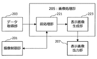
以上説明したような各種装置と連携しながらPDDを行う光線力学診断装置1は、図2に模式的に示したように、撮像ユニット10と、演算処理ユニット20と、画像表示ユニット30と、を主に備える。
The
撮像ユニット10は、光感受性物質が予め投与されている人体の少なくとも一部に対して所定波長の励起光を照射し、かかる励起光によって励起された光感受性物質からの蛍光を撮像することで、蛍光撮像画像を生成するユニットである。また、撮像ユニット10は、所定波長の励起光とは別に、可視光帯域に属する照明光を更に照射する機構を有していてもよい。かかる撮像ユニット10の詳細な構成については、以下で改めて説明する。
The
演算処理ユニット20は、撮像ユニット10により生成された蛍光撮像画像に対して所定の画像処理を施すことで、光線力学診断装置1の使用者(すなわち、悪性腫瘍の切除手術の術者)に対して、蛍光撮像画像をわかりやすい形式で提供するための画像データを生成するユニットである。この際、演算処理ユニット20は、光線力学診断装置1の外部に設けられた画像サーバ5から各種の画像データを取得して、演算処理ユニット20において実施される画像処理に供することが可能である。
The
また、演算処理ユニット20は、撮像ユニット10にて実施される各種の撮像処理を制御する制御ユニットとしての機能も有しており、撮像ユニット10として設けられている各種の光源や撮像装置や各種光学機器の制御を行うことが可能である。また、演算処理ユニット20は、照明光源3から照射される照明光の制御を行うことも可能である。
The
かかる演算処理ユニット20の詳細な構成についても、以下で改めて説明する。
The detailed configuration of the
画像表示ユニット30は、演算処理ユニット20で蛍光撮像画像に対して画像処理が施されることで生成される各種の画像データを、光線力学診断装置1の使用者に対して提示するためのユニットである。この画像表示ユニット30は、1又は複数の各種ディスプレイ等から構成されている。かかる画像表示ユニット30における各種の画像表示は、演算処理ユニット20によって制御される。画像表示ユニット30によって、理解が容易なように加工された蛍光撮像画像が、光線力学診断装置1の使用者に対して提示される。これにより、光線力学診断装置1の使用者は、光感受性物質からの蛍光の有無(すなわち、悪性細胞の残存の有無)を把握可能になるとともに、悪性細胞が残存している場合には、その残存箇所をも容易に把握することが可能となる。
The
以上、図1及び図2を参照しながら、本実施形態に係る光線力学診断装置1の全体構成について、詳細に説明した。
The overall configuration of the
<撮像ユニット10の構成について>
次に、図3〜図5を参照しながら、本実施形態に係る光線力学診断装置1が備える撮像ユニット10の構成について、詳細に説明する。図3は、本実施形態に係る光線力学診断装置の撮像ユニットの構成の一例を模式的に示した説明図である。図4は、光感受性物質とその励起波長について説明するための説明図である。図5は、本実施形態に係る撮像ユニットの他の構成例を模式的に示した説明図である。
<About Configuration of
Next, the configuration of the
本実施形態に係る撮像ユニット10は、図3に模式的に示したように、励起光源101と、蛍光撮像装置103と、を少なくとも備える。
As schematically illustrated in FIG. 3, the
励起光源101は、光感受性物質が蓄積している病巣部(すなわち、癌などの悪性腫瘍)を含む人体の少なくとも一部に対して、所定波長の励起光を照射する光源である。励起光源101から照射される励起光の波長は、特に限定されるものではなく、病巣部に予め蓄積されている光感受性物質を励起するために求められる波長を選択すればよい。
The
図4は、光感受性物質の一例と、各光感受性物質に対応する励起波長と、をあわせて示したものである。光感受性物質は、その化学構造に応じて、光感受性物質を励起させるための励起波長が決まっている。例えば、光感受性物質の一例であるPhotofrin(登録商標)は、波長630nmの励起光によって励起されて、所定波長の蛍光を発する。同様に、光感受性物質Visudyne(登録商標)は、波長693nmの励起光、又は、波長689nm±3nmの励起光により励起されて所定波長の蛍光を発し、光感受性物質Laserphyrin(登録商標)は、波長664nmの励起光により励起されて所定波長の蛍光を発する。光感受性物質Foscan(登録商標)は、波長652nmの励起光により励起されて所定波長の蛍光を発し、光感受性物質Levulan(登録商標)は、青色光により励起されて所定波長の蛍光を発する。光感受性物質Photorex(登録商標)は、波長660nmの励起光により励起されて所定波長の蛍光を発し、光感受性物質Antrin(登録商標)は、波長732nmの励起光により励起されて所定波長の蛍光を発し、光感受性物質Tookad(登録商標)は、波長762nmの励起光により励起されて所定波長の蛍光を発する。 FIG. 4 shows an example of a photosensitive substance and the excitation wavelength corresponding to each photosensitive substance. The excitation wavelength for exciting the photosensitive substance is determined according to the chemical structure of the photosensitive substance. For example, Photofrin (registered trademark), which is an example of a photosensitive substance, is excited by excitation light having a wavelength of 630 nm and emits fluorescence having a predetermined wavelength. Similarly, the photosensitive substance Visudyne (registered trademark) is excited by excitation light having a wavelength of 693 nm or excitation light having a wavelength of 689 nm ± 3 nm and emits fluorescence having a predetermined wavelength, and the photosensitive substance Laserphyrin (registered trademark) has a wavelength of It is excited by 664 nm excitation light and emits fluorescence of a predetermined wavelength. The photosensitive material Foscan (registered trademark) is excited by excitation light having a wavelength of 652 nm to emit fluorescence having a predetermined wavelength, and the photosensitive material Levlan (registered trademark) is excited by blue light to emit fluorescence having a predetermined wavelength. The photosensitizer Photorex (registered trademark) is excited by excitation light having a wavelength of 660 nm to emit fluorescence having a predetermined wavelength, and the photosensitizer Antrin (registered trademark) is excited by excitation light having a wavelength of 732 nm to emit fluorescence having a predetermined wavelength. The photosensitive substance Tookad (registered trademark) is excited by excitation light having a wavelength of 762 nm and emits fluorescence having a predetermined wavelength.
なお、図4に示した光感受性物質及びその励起波長は、あくまでも一例にすぎず、本実施形態に係る光線力学診断装置1で利用可能な光感受性物質が図4に示した例に限定されるものではない。
Note that the photosensitive substance and the excitation wavelength shown in FIG. 4 are merely examples, and the photosensitive substance that can be used in the photodynamic
撮像ユニット10に設けられている励起光源101は、図4に示したように、用いられている光感受性物質に応じて、出射する励起光の波長が設定される。
As shown in FIG. 4, the
なお、図3では、励起光源101の個数は1つとなっているが、励起光源101の個数は1つに限定されるものではなく、光線力学診断装置1で利用される光感受性物質の種類に応じて複数の光源が準備されていてもよい。また、励起光源101は、波長変換機構を有しており、複数の励起波長に対応可能なように設計されていてもよい。
In FIG. 3, the number of excitation
このような励起光源101の種別については、特に限定されるものではなく、公知の各種のレーザ光源を、必要に応じて各種レンズ等を利用して拡散光としながら利用することが可能である。ここで、レーザ光源としては、CW(Continuous Wave)レーザ光を出力可能なCWレーザ光源であってもよいし、パルスレーザ光を出力可能なパルスレーザ光源であってもよい。また、光感受性物質を励起するための出力が得られるのであれば、発光ダイオード等の光学素子を用いることも可能である。
The type of the
蛍光撮像装置103は、励起光源101からの励起光により励起された光感受性物質からの蛍光を撮像して、蛍光撮像画像(すなわち、PDD画像)を生成する装置である。以下では、蛍光撮像装置103によって生成される蛍光撮像画像のことを、PDD画像とも称することとする。かかる蛍光撮像装置103は、例えば、CCD(Charge Coupled Device)やCMOS(Complementary Metal Oxide Semiconductor)等といった各種の撮像素子、又は、光電子増倍管(PhotoMultiplier Tube:PMT)等の光検出器を有しており、光感受性物質からの蛍光の検出結果を、画像データへと変換する。これにより、光感受性物質に由来する蛍光撮像画像の画像データが生成される。
The
なお、本実施形態に係る蛍光撮像装置103では、光感受性物質からの蛍光をより鮮明に撮像するために、光感受性物質からの蛍光を透過させるとともに、励起光を透過させないための光学フィルタ105を、蛍光撮像装置103の上流側に設けることが好ましい。なお、図3では、蛍光撮像装置103の外側に光学フィルタ105を設ける場合について図示しているが、光学フィルタ105は、蛍光撮像装置103に設けられた各種の撮像素子よりも上流側に設けられてれさえすればよく、蛍光撮像装置103に内蔵されていてもよい。
In the
また、本実施形態に係る撮像ユニット10は、照明光源3から照射されている可視光帯域に属する照明光を利用して、光感受性物質が予め投与された人体の一部を撮像することで照明光撮像画像を生成する照明光撮像装置107を更に有することが好ましい。この際に、照明光撮像装置107と蛍光撮像装置103との相対的な位置関係(例えば、それぞれの撮像装置の光軸がなす角度等)が予め所定の値に設定されており、例えば照明光撮像装置107の光軸の向きが特定されることで、蛍光撮像装置103の光軸の向きが特定可能なようになっていることが好ましい。
Moreover, the
かかる照明光撮像装置107によって生成される照明光撮像画像は、可視光帯域に属する照明光下での撮像画像であり、光線力学診断装置1の使用者(すなわち、切除手術の術者)が手術時に実際に見ている画像となる。
The illumination light captured image generated by the illumination
なお、図3では、蛍光撮像装置103と照明光撮像装置107とがそれぞれ別の装置として記載されている。ここで、光学フィルタ105の光軸上への挿入及び光軸上からの除去を高速に実施することが可能であり、撮像装置にカラー画像が撮像可能な撮像素子が設けられていれば、1つの撮像装置で蛍光撮像装置103及び照明光撮像装置107の機能を実現させることも可能である。しかしながら、図3に示したように、蛍光を撮像する蛍光撮像装置103と、照明光を撮像する照明光撮像装置107とを別々に設けることで、光学フィルタ105の挿入・除去といった処理を行わなくとも良くなり、撮像ユニット10の安定性を更に向上させることができる。
In FIG. 3, the
また、図3では、可視光帯域に属する照明光を照射する照明光源3が、撮像ユニット10とは別に設けられている場合を図示しているが、撮像ユニット10自体が照明光源を有していても良いことは、前述の通りである。かかる照明光源は、可視光帯域に属する照明光を照射可能なものであれば、特に限定されるものではなく、公知の光源を利用することが可能である。
3 shows a case where the
また、図3では、蛍光撮像装置103と照明光撮像装置107とが別の装置として記載されているが、図5に示したように、蛍光撮像装置103と照明光撮像装置107とを一体化することも可能である。図5に示した一体化された撮像装置(一体化撮像装置111)では、病巣部からの蛍光が結像する蛍光撮像用撮像素子151と、病巣部からの照明光が結像する照明光撮像用撮像素子153とが、カメラ本体の内部に設けられている。病巣部からの光は、レンズを介してカメラ本体まで導光された後、光軸上に設けられたビームスプリッタBSによって、光路が2つに分岐される。一方の光路上には、光学フィルタ105が設けられており、かかる光学フィルタ105の後段に蛍光撮像用撮像素子151が設けられている。また、もう一方の光路上には、照明光撮像用撮像素子153が設けられている。
In FIG. 3, the
図5に示したような一体化撮像装置111を用いることで、図3では異なっていた蛍光撮像装置103の光軸と照明光撮像装置107の光軸とが一致することとなり、照明光撮像用撮像素子153に結像している画像に対応する光軸の方向は、蛍光撮像用撮像素子151に結像している画像に対応する光軸の方向と等しくなる。その結果、以下で詳述するような、蛍光撮像画像と他の画像との統合処理に際しての統合前処理を、より簡便に実施することが可能となる。更に、図3に示した構成と比べて、省スペース化を図ることが可能となる。
By using the integrated
以上、図3〜図5を参照しながら、本実施形態に係る撮像ユニット10の構成について、詳細に説明した。
The configuration of the
<演算処理ユニット20の構成について>
次に、図6〜図10を参照しながら、本実施形態に係る演算処理ユニット20の構成について、詳細に説明する。図6は、本実施形態に係る光線力学診断装置の演算処理ユニットの構成の一例を模式的に示したブロック図である。図7は、本実施形態に係る演算処理ユニットが備える画像処理部の構成の一例を模式的に示したブロック図である。図8〜図10は、本実施形態に係る画像処理部で実施される表示画像の生成処理を説明するための説明図である。
<Configuration of the
Next, the configuration of the
本実施形態に係る演算処理ユニット20は、図6に模式的に示したように、撮像制御部201と、データ取得部203と、画像処理部205と、表示画像出力部207と、表示制御部209と、記憶部211と、を主に備える。
As schematically shown in FIG. 6, the
撮像制御部201は、例えば、CPU(Central Processing Unit)、ROM(Read Only Memory)、RAM(Random Access Memory)、通信装置等により実現される。撮像制御部201は、撮像ユニット10における各種の撮像処理を制御する。より詳細には、撮像制御部201は、撮像ユニット10における励起光源101のオン・オフ制御や、蛍光撮像装置103及び照明光撮像装置107の駆動制御を行う。
The
また、撮像制御部201は、照明光源3における照明光のオン・オフ制御を行うことが可能であり、撮像ユニット10自体が可視光帯域に属する照明光を照射可能な照明光源を有している場合には、かかる照明光源における照明光のオン・オフ制御を行うことも可能である。
The
データ取得部203は、例えば、CPU、ROM、RAM、通信装置等により実現される。データ取得部203は、撮像ユニット10により生成された蛍光撮像画像(PDD画像)や照明光撮像画像に関する画像データを、撮像ユニット10から随時取得する。また、データ取得部203は、画像サーバ5等の外部サーバに格納されている各種の診断画像に関する画像データを、該当するサーバから必要に応じて随時取得する。データ取得部203は、取得したこれらの画像データを、後述する画像処理部205に出力する。また、データ取得部203は、取得したこれらの画像データを、後述する記憶部211等に格納してもよい。
The
画像処理部205は、例えば、CPU、ROM、RAM等により実現される。画像処理部205は、データ取得部203から出力された蛍光撮像画像(PDD画像)に対して、以下で詳述するような画像処理を施して、人体の少なくとも一部の位置関係を表わした第1の画像を蛍光撮像画像に対して統合した統合画像を生成する。この統合画像は、2次元画像であってもよいし、立体視することが可能な3次元画像であってもよい。ここで、蛍光撮像画像に統合される第1の画像は、人体の少なくとも一部の位置関係を表わしたものであり、光感受性物質が取り込まれている悪性腫瘍の切除手術における術野を撮像した画像(すなわち、照明光撮像画像)、又は、悪性腫瘍の存在位置を示した診断画像(すなわち、画像サーバ5等に格納されている各種診断画像)の少なくとも何れかである。
The
蛍光撮像画像に対して、照明光撮像画像のような人体の少なくとも一部の位置関係が表わされた画像が統合されることで、光線力学診断装置1の使用者は、悪性腫瘍の有無を容易に把握できるとともに、術野のどこに悪性腫瘍が存在するのかを、容易に把握することが可能となる。その結果、先だって説明したような断端陽性リスクを低減させることができる。更に、かかる統合画像に対して、マンモグラフィ画像、CT画像、MRI画像、超音波画像といった、人体の少なくとも一部の位置関係に加えて悪性腫瘍の位置関係が表わされた各種の診断画像が統合されることで、悪性腫瘍がどのように広がっているかという診断画像から示唆される情報を、統合画像に更に重畳させることが可能となる。
By integrating an image representing at least a part of the human body, such as an illumination light captured image, with the fluorescence captured image, the user of the
なお、画像処理部205は、統合画像を生成する際に、蛍光撮像画像に対して各種の前処理を実施した後に、上記のような第1の画像と統合させることが好ましい。この前処理を実施する際に、蛍光撮像画像の撮像条件を変更することが好ましい場合には、画像処理部205は、撮像制御部201と互いに連携しながら、蛍光撮像画像の撮像条件を変更させることが可能である。
In addition, when generating the integrated image, the
画像処理部205は、生成した統合画像に対して、悪性腫瘍の存在する場所に対応する蛍光が結像している領域(蛍光結像領域)を強調する各種の表示オブジェクトを、更に重畳させてもよい。また、画像処理部205は、蛍光結像領域の存在及び位置を強調するために、蛍光結像領域の色調を、本来の蛍光色とは異なる色調(例えば、生体には存在し得ない、ピンク色や緑色等)に変更してもよい。
The
このような統合画像の生成処理を実施する画像処理部205の詳細な構成については、以下で改めて説明する。
The detailed configuration of the
画像処理部205は、生成した統合画像に関する画像データを、後述する表示画像出力部207に出力する。
The
表示画像出力部207は、例えば、CPU、ROM、RAM、通信装置等により実現される。表示画像出力部207は、画像処理部205により生成された、蛍光撮像画像(PDD画像)に対して、PDD画像とは異なる第1の画像が統合された統合画像を、演算処理ユニット20の外部に対して出力する。この際、かかる統合画像を画像表示ユニット30として設けられたディスプレイ等に出力する際には、かかる統合画像の画像データを表示制御部209に出力して、表示制御部209により統合画像の表示制御を実施させる。
The display
また、表示画像出力部207は、生成された統合画像の画像データや、統合画像の基となったPDD画像の画像データを、画像サーバ5等の外部のサーバに出力してもよい。更に、表示画像出力部207は、生成された統合画像を、印刷物として出力してもよい。
The display
表示制御部209は、例えば、CPU、ROM、RAM、通信装置等により実現される。表示制御部209は、表示画像出力部207から伝送された、蛍光撮像画像(PDD画像)に対して、PDD画像とは異なる第1の画像が統合された統合画像を、画像表示ユニット30が備えるディスプレイ等の出力装置や光線力学診断装置1の外部に設けられた出力装置等に表示する際の表示制御を行う。これにより、光線力学診断装置1の利用者は、生成された統合画像をその場で把握することが可能となる。
The
記憶部211は、例えば本実施形態に係る演算処理ユニット20が備えるRAMやストレージ装置等により実現される。記憶部211には、本実施形態に係る演算処理ユニット20が、何らかの処理を行う際に保存する必要が生じた様々なパラメータや処理の途中経過等、又は、各種のデータベースやプログラム等が、適宜記録される。この記憶部211は、撮像制御部201、データ取得部203、画像処理部205、表示画像出力部207、表示制御部209等が、データのリード/ライト処理を自由に行うことが可能である。
The
[画像処理部205の構成について]
続いて、図7〜図10を参照しながら、画像処理部205の詳細な構成について説明する。
本実施形態に係る画像処理部205は、図7に模式的に示したように、前処理部221と、表示画像生成部223と、を有している。
[Configuration of the image processing unit 205]
Next, a detailed configuration of the
As schematically illustrated in FIG. 7, the
前処理部221は、例えば、CPU、ROM、RAM等により実現される。前処理部221は、データ取得部203から伝送された蛍光撮像画像(PDD画像)や照明光撮像画像に対して、表示倍率の調整処理、及び、上記第1の画像との間の位置合わせ処理を少なくとも含む統合前処理を実施する。
The
これらの統合前処理は、図8に示したように、カメラ角度の特定処理、撮像倍率の校正処理、及び、撮像位置の校正処理を少なくとも含むことが好ましい。 As shown in FIG. 8, these pre-integration processes preferably include at least a camera angle specifying process, an imaging magnification calibration process, and an imaging position calibration process.
カメラ角度の特定処理は、照明光撮像画像における人体の少なくとも一部を、例えば公知の画像認識処理等を利用して認識し、カメラの向いている方向を特定する処理である。これにより、照明光撮像装置107の光軸が、例えば人体の頭側の方向や尾側の方向のどちらに向いているのかを特定することが可能となる。また、更なる詳細な認識処理を行えば、照明光撮像装置107の光軸が向いている方向(ある基準方向からの回転角)を具体的に特定することが可能となる。
The camera angle specifying process is a process of recognizing at least a part of the human body in the illumination light captured image using, for example, a well-known image recognition process, and specifying the direction in which the camera is facing. As a result, it is possible to specify whether the optical axis of the illumination
ここで、照明光撮像装置107と、蛍光撮像装置103とは、相対的な位置関係が予め設定されていることから、照明光撮像画像を利用した上記のような処理を実施することで、蛍光撮像装置103の光軸が向いている方向を特定することが可能となる。
Here, since the relative positional relationship between the illumination
このようなカメラ角度の特定処理は、蛍光撮像装置103や照明光撮像装置107について同一の撮像条件で撮像処理が実施されている間は、少なくとも1回実施すればよい。また、蛍光撮像装置103や照明光撮像装置107の撮像条件が変更となった場合には、その都度カメラ角度の特定処理を実施すればよい。
Such a camera angle specifying process may be performed at least once while the
撮像倍率の校正処理は、撮像装置の焦点位置(すなわち、患者の術野)におけるカメラの撮像倍率を校正する処理である。照明光撮像装置107の焦点位置において、どの程度の範囲が視野に含まれるかを特定することで、統合対象としたい(照明光撮像画像とは異なる)第1の画像の表示倍率と、照明光撮像画像の表示倍率との違いを特定することができる。これにより、照明光撮像画像を第1の画像と統合する際に、撮像された画像をどの程度拡大(又は縮小)すればよいかを把握することが可能となる。また、照明光撮像装置107と蛍光撮像装置103との相対的な位置関係は既知であることから、照明光撮像画像における撮像倍率の校正度合いを決定することで、蛍光撮像画像における撮像倍率の校正度合いを決定することができる。なお、上記のような倍率の校正後に、撮像装置のズーミング動作が行われた場合には、ズーミング倍率に基づいて、適宜校正を行えばよい。
The imaging magnification calibration process is a process of calibrating the imaging magnification of the camera at the focal position of the imaging apparatus (that is, the patient's surgical field). By specifying what range is included in the field of view at the focal position of the illumination
撮像位置の校正処理は、蛍光撮像画像と第1の画像との位置関係が適合するように、撮像位置の校正を行う処理である。より詳細には、撮像方向及び表示倍率に関する知見を利用して、照明光撮像画像における人体の特定の器官(例えば、乳癌の手術であれば、乳首等)の位置と、第1の画像における同器官の位置とを一致させる位置合わせパラメータが算出される。その後、算出された位置合わせパラメータを利用して、蛍光撮像画像と第1の画像との位置合わせが行われる。この際に、照明光撮像画像において、第1の画像に含まれる人体の特定の器官が視野に含まれていない場合には、前処理部221は、撮像制御部201と連携して、着目している器官が視野に含まれるように、撮像条件を変更する。
The imaging position calibration process is a process of calibrating the imaging position so that the positional relationship between the fluorescence captured image and the first image is matched. More specifically, using knowledge about the imaging direction and display magnification, the position of a specific organ of the human body (for example, nipple in the case of breast cancer surgery) in the illumination light captured image and the same in the first image. An alignment parameter that matches the position of the organ is calculated. Thereafter, using the calculated alignment parameter, alignment between the fluorescence captured image and the first image is performed. At this time, in the illumination light captured image, when a specific organ of the human body included in the first image is not included in the visual field, the
以上のような統合前処理が実施されることで、通常は実際の大きさよりも拡大されて表示されることが多い第1の画像(特に、各種の診断画像)に対して、術中に得られた蛍光撮像画像や照明光撮像画像を、表示倍率を一致させた上で統合することが可能となる。 By performing the integration pre-processing as described above, the first image (especially various diagnostic images) that is usually displayed in an enlarged size than the actual size is obtained during the operation. It is possible to integrate the fluorescence captured image and the illumination light captured image with the same display magnification.
蛍光撮像画像と第1の画像とを同じ倍率で表示させることにより、術者は、診断画像と手術時に得られるPDD画像や術野の観察画像と、を高精度に比較することが可能となる。その結果、術者は、診断画像に存在する癌などの悪性腫瘍の位置を、人体の位置関係に基づいて容易に把握することが可能となり、切除すべき領域を容易に決定することが可能となる。 By displaying the fluorescence image and the first image at the same magnification, the surgeon can compare the diagnostic image with the PDD image obtained at the time of surgery and the observation image of the surgical field with high accuracy. . As a result, the surgeon can easily grasp the position of a malignant tumor such as cancer present in the diagnostic image based on the positional relationship of the human body, and can easily determine the region to be excised. Become.
ここで、本実施形態に係る撮像ユニット10において、図5に示したような一体化撮像装置111が用いられている場合には、上記のような各種の校正処理をより簡便に実施することが可能となるため、好ましい。
Here, in the
なお、上記の説明では、前処理部221は、主に蛍光撮像画像に対して、上記のような各種の統合前処理を実施する旨について言及したが、前処理部221は、同様の統合前処理を、照明光撮像画像に対して実施してもよい。また、前処理部221は、統合対象とする照明光撮像画像以外の第1の画像(例えば、各種の診断画像)に対しても、画像の拡大・縮小、回転等といった各種の画像処理を施しても良い。
In the above description, the
前処理部221は、上記のようにして対象となる撮像画像に対して統合前処理を行った後、統合前処理後の画像データを、表示画像生成部223に出力する。
The
表示画像生成部223は、例えば、CPU、ROM、RAM等により実現される。表示画像生成部223は、前処理部221から伝送された統合前処理後の画像データを利用して、蛍光撮像画像と、人体の少なくとも一部の位置関係を表わした第1の画像と、が統合された統合画像を生成する。これにより、図8に模式的に示したように、統合前処理後の蛍光撮像画像及び照明光撮像画像が互いに統合された統合画像や、統合前処理後の蛍光撮像画像と、マンモグラフィ画像、CT画像、MRI画像、超音波画像等のような診断画像の少なくとも1つと、が互いに統合された統合画像や、統合前処理後の蛍光撮像画像及び照明光撮像画像と、少なくとも1つの診断画像と、が互いに統合された統合画像等が生成される。
The display
この際、表示画像生成部223は、図9に模式的に示したように、蛍光撮像画像(PDD画像)における蛍光結像領域の色調を、光感受性物質に由来する本来の蛍光の色調ではなく、統合させた画像には存在しない色調に変更することが好ましい。これにより、蛍光結像領域の存在が統合画像中に埋没してしまい、統合画像を参照した光線力学診断装置1の使用者が、蛍光結像領域の存在に気付かないという事態を防止することが可能となり、断端陽性リスクの低減を図ることができる。
At this time, as schematically shown in FIG. 9, the display
このような色調を変えるための方法としては、例えば、蛍光撮像画像(PDD画像)から得られる画像の輝度情報を、統合画像の画像データのG(Green)チャンネルに入力する等の方法が考えられる。また、蛍光撮像画像における蛍光結像領域の色調に関する画像データを直接書き換えて、所望の色調に対応する値に変更してもよい。 As a method for changing the color tone, for example, a method of inputting luminance information of an image obtained from a fluorescent captured image (PDD image) to a G (Green) channel of image data of an integrated image is conceivable. . Further, the image data related to the color tone of the fluorescence imaging region in the fluorescence captured image may be directly rewritten and changed to a value corresponding to a desired color tone.
また、表示画像生成部223は、蛍光結像領域を強調して表示させるために、蛍光結像領域を強調する表示オブジェクトobjを、統合画像に対して更に重畳させてもよい。このような表示オブジェクトobjとしては、例えば、図10に模式的に示したように、蛍光結像領域を例えば点線などで囲むオブジェクトobjがある。また、蛍光結像領域を表わすような各種のマーカーオブジェクトを統合画像に重畳させてもよいし、蛍光結像領域を点滅させながら表示する等のような表示効果を併用してもよい。このような表示オブジェクトobjを更に重畳させることで、光線力学診断装置1の使用者が蛍光結像領域の存在を見落とすという可能性を抑制することが可能となり、断端陽性リスクの低減が可能となる。
Further, the display
表示画像生成部223は、このようにして生成した統合画像に関する画像データを、表示画像出力部207に出力する。これにより、光線力学診断装置1の使用者は、画像表示ユニット30への画像の表示も含めた様々な方法で、PDDを実施することが可能となる。
The display
前述のように、例えば現在の乳癌手術においては、例えばマンモグラフィ画像などの診断画像をもとに、患者の乳房状にマーカーペンを用いて切除目標領域を表わす印をつけることが一般的である。しかしながら、このような処理では、診断画像における立体的な手術切除領域を平面透視情報とすることで、診断画像が有している情報の一部を消失させてしまっている。一方で、上記のような統合画像を利用することで、診断画像が有している情報をより効率的に利用することが可能となり、従来の方法では失われてしまう可能性のある情報を補うことが可能となる。 As described above, for example, in current breast cancer surgery, for example, based on a diagnostic image such as a mammography image, it is common to mark the patient's breast using a marker pen to indicate the target region for resection. However, in such a process, a part of information included in the diagnostic image has been lost by using the three-dimensional surgical excision region in the diagnostic image as the plane perspective information. On the other hand, by using the integrated image as described above, it becomes possible to more efficiently use information included in the diagnostic image, and compensate for information that may be lost by the conventional method. It becomes possible.
以上、図7を参照しながら、本実施形態に係る画像処理部205の構成について、詳細に説明した。
The configuration of the
以上、本実施形態に係る演算処理ユニット20の機能の一例を示した。上記の各構成要素は、汎用的な部材や回路を用いて構成されていてもよいし、各構成要素の機能に特化したハードウェアにより構成されていてもよい。また、各構成要素の機能を、CPU等が全て行ってもよい。従って、本実施形態を実施する時々の技術レベルに応じて、適宜、利用する構成を変更することが可能である。
Heretofore, an example of the function of the
なお、上述のような本実施形態に係る演算処理ユニットの各機能を実現するためのコンピュータプログラムを作製し、パーソナルコンピュータ等に実装することが可能である。また、このようなコンピュータプログラムが格納された、コンピュータで読み取り可能な記録媒体も提供することができる。記録媒体は、例えば、磁気ディスク、光ディスク、光磁気ディスク、フラッシュメモリなどである。また、上記のコンピュータプログラムは、記録媒体を用いずに、例えばネットワークを介して配信してもよい。 Note that a computer program for realizing each function of the arithmetic processing unit according to the present embodiment as described above can be produced and installed in a personal computer or the like. In addition, a computer-readable recording medium storing such a computer program can be provided. The recording medium is, for example, a magnetic disk, an optical disk, a magneto-optical disk, a flash memory, or the like. Further, the above computer program may be distributed via a network, for example, without using a recording medium.
<光線力学診断方法について>
次に、図11を参照しながら、本実施形態に係る光線力学診断方法の流れについて、簡単に説明する。図11は、本実施形態に係る光線力学診断方法の流れの一例を示した流れ図である。
<About photodynamic diagnosis method>
Next, the flow of the photodynamic diagnosis method according to the present embodiment will be briefly described with reference to FIG. FIG. 11 is a flowchart showing an example of the flow of the photodynamic diagnosis method according to the present embodiment.
本実施形態に係る光線力学診断方法では、まず、患者に予め所定の光感受性物質を投与して(ステップS101)、癌などの悪性腫瘍に光感受性物質が蓄積されるようにする。その後、手術時において、光線力学診断装置1の演算処理ユニット20の制御下で撮像ユニット10を駆動させて、悪性腫瘍が存在すると思われる場所(病巣部)を含むように、光線力学診断装置1の撮像ユニット10の励起光源101から、光感受性物質を励起することが可能な波長を有する励起光を術野に向けて照射させる(ステップS103)。
In the photodynamic diagnosis method according to this embodiment, first, a predetermined photosensitive substance is administered to a patient in advance (step S101), and the photosensitive substance is accumulated in a malignant tumor such as cancer. Thereafter, at the time of surgery, the
着目している術野に光感受性物質が蓄積されている場合には、照射した励起光に起因して蛍光が発生する。そこで、光線力学診断装置1の撮像ユニット10の蛍光撮像装置103により病巣部からの蛍光を撮像して、PDD画像を生成する。また、PDD画像の生成に加えて、撮像ユニット10の照明光撮像装置107を利用して、照明光撮像画像を生成することが好ましい。
When a photosensitive substance is accumulated in the surgical field of interest, fluorescence is generated due to the irradiated excitation light. Therefore, the
撮像ユニット10により各種の撮像画像が生成されると、生成された撮像画像の画像データは、演算処理ユニット20へと出力される。演算処理ユニット20のデータ取得部203は、撮像ユニット10により生成された各種の撮像画像の画像データを取得すると、得られた画像データを画像処理部205の前処理部221に出力する。
When various captured images are generated by the
画像処理部205の前処理部221は、上記のような統合前処理を、PDD画像や照明光撮像画像に対して実施する(ステップS107)。その後、前処理部221は、統合前処理後のPDD画像や照明光撮像画像の画像データを、表示画像生成部223へと出力する。
The
その後、画像処理部205の表示画像生成部223は、別途データ取得部203が画像サーバ5等から取得していた診断画像等を利用して、上記のような方法により、PDD画像と、PDD画像とは異なる画像と、を統合する(ステップS109)。これにより、本実施形態に係る統合画像が生成される。その後、表示画像生成部223は、生成した統合画像に関する画像データを、表示画像出力部207に出力する。
Thereafter, the display
表示画像出力部207は、画像処理部205から統合画像に関する画像データが出力されると、かかる統合画像を出力する(ステップS111)。例えば、統合画像を画像表示ユニット30のディスプレイ等に表示させる場合には、表示画像出力部207は、統合画像に関する画像データを表示制御部209に出力して、画像表示ユニット30の表示制御を、表示制御部209に実施させる。これにより、生成された統合画像が、光線力学診断装置1の使用者に提示されることとなる。
When the image data related to the integrated image is output from the
以上、図11を参照しながら、本実施形態に係る光線力学診断方法の流れの一例について、簡単に説明した。 The example of the flow of the photodynamic diagnosis method according to the present embodiment has been briefly described above with reference to FIG.
(ハードウェア構成について)
次に、図12を参照しながら、本開示の実施形態に係る演算処理ユニット20のハードウェア構成について、詳細に説明する。図12は、本開示の実施形態に係る演算処理ユニット20のハードウェア構成を説明するためのブロック図である。
(About hardware configuration)
Next, the hardware configuration of the
演算処理ユニット20は、主に、CPU901と、ROM903と、RAM905と、を備える。また、演算処理ユニット20は、更に、ホストバス907と、ブリッジ909と、外部バス911と、インターフェース913と、入力装置915と、出力装置917と、ストレージ装置919と、ドライブ921と、接続ポート923と、通信装置925とを備える。
The
CPU901は、演算処理装置及び制御装置として機能し、ROM903、RAM905、ストレージ装置919、又は、リムーバブル記録媒体927に記録された各種プログラムに従って、演算処理ユニット20内の動作全般又はその一部を制御する。ROM903は、CPU901が使用するプログラムや演算パラメータ等を記憶する。RAM905は、CPU901が使用するプログラムや、プログラムの実行において適宜変化するパラメータ等を一次記憶する。これらはCPUバス等の内部バスにより構成されるホストバス907により相互に接続されている。
The
ホストバス907は、ブリッジ909を介して、PCI(Peripheral Component Interconnect/Interface)バスなどの外部バス911に接続されている。
The
入力装置915は、例えば、マウス、キーボード、タッチパネル、ボタン、スイッチ及びレバーなどユーザが操作する操作手段である。また、入力装置915は、例えば、赤外線やその他の電波を利用したリモートコントロール手段(いわゆる、リモコン)であってもよいし、光線力学診断装置1の操作に対応した携帯電話やPDA等の外部接続機器929であってもよい。更に、入力装置915は、例えば、上記の操作手段を用いてユーザにより入力された情報に基づいて入力信号を生成し、CPU901に出力する入力制御回路などから構成されている。光線力学診断装置1のユーザは、この入力装置915を操作することにより、光線力学診断装置1に対して各種のデータを入力したり処理動作を指示したりすることができる。
The
出力装置917は、取得した情報をユーザに対して視覚的または聴覚的に通知することが可能な装置で構成される。このような装置として、CRTディスプレイ装置、液晶ディスプレイ装置、プラズマディスプレイ装置、ELディスプレイ装置及びランプなどの表示装置や、スピーカ及びヘッドホンなどの音声出力装置や、プリンタ装置、携帯電話、ファクシミリなどがある。出力装置917は、例えば、演算処理ユニット20が行った各種処理により得られた結果を出力する。具体的には、表示装置は、演算処理ユニット20が行った各種処理により得られた結果を、テキスト又はイメージで表示する。他方、音声出力装置は、再生された音声データや音響データ等からなるオーディオ信号をアナログ信号に変換して出力する。
The
ストレージ装置919は、演算処理ユニット20の記憶部の一例として構成されたデータ格納用の装置である。ストレージ装置919は、例えば、HDD(Hard Disk Drive)等の磁気記憶部デバイス、半導体記憶デバイス、光記憶デバイス、または光磁気記憶デバイス等により構成される。このストレージ装置919は、CPU901が実行するプログラムや各種データ、及び、外部から取得した各種データなどを格納する。
The
ドライブ921は、記録媒体用リーダライタであり、演算処理ユニット20に内蔵、あるいは外付けされる。ドライブ921は、装着されている磁気ディスク、光ディスク、光磁気ディスク、又は、半導体メモリ等のリムーバブル記録媒体927に記録されている情報を読み出して、RAM905に出力する。また、ドライブ921は、装着されている磁気ディスク、光ディスク、光磁気ディスク、又は、半導体メモリ等のリムーバブル記録媒体927に記録を書き込むことも可能である。リムーバブル記録媒体927は、例えば、DVDメディア、HD−DVDメディア、Blu−ray(登録商標)メディア等である。また、リムーバブル記録媒体927は、コンパクトフラッシュ(登録商標)(CompactFlash:CF)、フラッシュメモリ、または、SDメモリカード(Secure Digital memory card)等であってもよい。また、リムーバブル記録媒体927は、例えば、非接触型ICチップを搭載したICカード(Integrated Circuit card)又は電子機器等であってもよい。
The
接続ポート923は、機器を演算処理ユニット20に直接接続するためのポートである。接続ポート923の一例として、USB(Universal Serial Bus)ポート、IEEE1394ポート、SCSI(Small Computer System Interface)ポート等がある。接続ポート923の別の例として、RS−232Cポート、光オーディオ端子、HDMI(High−Definition Multimedia Interface)ポート等がある。この接続ポート923に外部接続機器929を接続することで、光線力学診断装置1は、外部接続機器929から直接各種データを取得したり、外部接続機器929に各種データを提供したりする。
The
通信装置925は、例えば、通信網931に接続するための通信デバイス等で構成された通信インターフェースである。通信装置925は、例えば、有線もしくは無線LAN(Local Area Network)、Bluetooth(登録商標)、又は、WUSB(Wireless USB)用の通信カード等である。また、通信装置925は、光通信用のルータ、ADSL(Asymmetric Digital Subscriber Line)用のルータ、又は、各種通信用のモデム等であってもよい。この通信装置925は、例えば、インターネットや他の通信機器との間で、例えばTCP/IP等の所定のプロトコルに則して信号等を送受信することができる。また、通信装置925に接続される通信網931は、有線または無線によって接続されたネットワーク等により構成され、例えば、インターネット、家庭内LAN、赤外線通信、ラジオ波通信又は衛星通信等であってもよい。
The
以上、本開示の実施形態に係る演算処理ユニット20の機能を実現可能なハードウェア構成の一例を示した。上記の各構成要素は、汎用的な部材を用いて構成されていてもよいし、各構成要素の機能に特化したハードウェアにより構成されていてもよい。従って、本実施形態を実施する時々の技術レベルに応じて、適宜、利用するハードウェア構成を変更することが可能である。
Heretofore, an example of a hardware configuration capable of realizing the function of the
以上、添付図面を参照しながら本開示の好適な実施形態について詳細に説明したが、本開示の技術的範囲はかかる例に限定されない。本開示の技術分野における通常の知識を有する者であれば、特許請求の範囲に記載された技術的思想の範疇内において、各種の変更例または修正例に想到し得ることは明らかであり、これらについても、当然に本開示の技術的範囲に属するものと了解される。 The preferred embodiments of the present disclosure have been described in detail above with reference to the accompanying drawings, but the technical scope of the present disclosure is not limited to such examples. It is obvious that a person having ordinary knowledge in the technical field of the present disclosure can come up with various changes or modifications within the scope of the technical idea described in the claims. Of course, it is understood that it belongs to the technical scope of the present disclosure.
また、本明細書に記載された効果は、あくまで説明的又は例示的なものであって限定的ではない。つまり、本開示に係る技術は、上記の効果とともに、又は、上記の効果に代えて、本明細書の記載から当業者には明らかな他の効果を奏しうる。 In addition, the effects described in the present specification are merely illustrative or illustrative, and are not limited. That is, the technology according to the present disclosure can exhibit other effects that are apparent to those skilled in the art from the description of the present specification in addition to or instead of the above effects.
なお、以下のような構成も本開示の技術的範囲に属する。
(1)所定波長の励起光を照射する励起光源、及び、前記励起光により励起された光感受性物質からの蛍光を撮像して蛍光撮像画像を生成する蛍光撮像装置を有する撮像ユニットと、
前記蛍光撮像画像に対して所定の画像処理を実施する画像処理部を有する演算処理ユニットと、
を備え、
前記画像処理部は、人体の少なくとも一部の位置関係を表わした第1の画像を前記蛍光撮像画像に対して統合した統合画像を生成する、光線力学診断装置。
(2)前記画像処理部は、前記蛍光撮像画像に対して、表示倍率の調整処理、及び、前記第1の画像との間の位置合わせ処理を少なくとも含む統合前処理を実施した後、統合前処理後の前記蛍光撮像画像と、前記第1の画像と、を統合する、(1)に記載の光線力学診断装置。
(3)前記撮像ユニットは、可視光帯域に属する照明光を利用して、前記光感受性物質が予め投与された人体の一部を撮像することで照明光撮像画像を生成する照明光撮像装置を更に有し、かつ、当該照明光撮像装置と前記蛍光撮像装置との相対的な位置関係が予め設定されており、
前記画像処理部は、
前記照明光撮像画像における人体の少なくとも一部を認識することで、前記照明光撮像装置及び前記蛍光撮像装置の撮像方向を特定し、
前記照明光撮像装置及び前記蛍光撮像装置の撮像倍率に基づき、生成される前記照明光撮像画像及び蛍光撮像画像の表示倍率を調整し、
前記撮像方向及び前記表示倍率を利用して、前記照明光撮像画像における人体の器官の位置と、前記第1の画像における前記人体の器官の位置とを一致させる位置合わせパラメータを算出し、
算出した前記位置合わせパラメータを利用して、前記蛍光撮像画像と前記第1の画像との位置合わせを行う、(2)に記載の光線力学診断装置。
(4)前記蛍光撮像装置及び前記照明光撮像装置は、一体化されており、一体化された撮像装置に入射した光線を2つの光路に分岐することで、前記蛍光撮像画像及び前記照明光撮像画像を生成する、(3)に記載の光線力学診断装置。
(5)前記撮像ユニットは、可視光帯域に属する照明光を照射する照明光源を更に有し、
前記演算処理ユニットは、前記撮像ユニットにおける撮像処理を制御する撮像制御部を更に有し、
前記撮像制御部は、前記励起光源及び前記照明光源のオン/オフ切り替え制御、並びに、前記蛍光撮像装置及び前記照明光撮像装置の駆動制御を実施する、(3)又は(4)に記載の光線力学診断装置。
(6)前記画像処理部は、前記統合画像において、前記蛍光撮像画像における蛍光結像領域に対応する領域の色調を、前記第1の画像には存在しない色調に変更する、(1)〜(5)の何れか1項に記載の光線力学診断装置。
(7)前記画像処理部は、前記統合画像に対して、当該統合画像における蛍光結像領域を強調する表示オブジェクトを更に重畳する、(1)〜(6)の何れか1項に記載の光線力学診断装置。
(8)前記第1の画像は、前記光感受性物質が取り込まれている悪性腫瘍の切除手術における術野を撮像した画像、又は、当該悪性腫瘍の存在位置を示した診断画像の少なくとも何れかである、(1)〜(7)の何れか1項に記載の光線力学診断装置。
(9)前記診断画像は、人体の少なくとも一部の透視画像又は断面画像の少なくとも何れかである、(8)に記載の光線力学診断装置。
(10)前記透視画像又は前記断面画像は、マンモグラフィ画像、CT画像、MRI画像、又は超音波画像である、(9)に記載の光線力学診断装置。
(11)前記演算処理ユニットは、外部に設けられた画像サーバから前記第1の画像を取得して、前記蛍光撮像画像と統合する、(1)〜(10)の何れか1項に記載の光線力学診断装置。
(12)励起光光源から所定波長の励起光を照射して、前記励起光により励起された光感受性物質からの蛍光を蛍光撮像装置により撮像して蛍光撮像画像を生成することと、
人体の少なくとも一部の位置関係を表わした第1の画像を、生成された前記蛍光撮像画像に対して統合した統合画像を生成することと、
を含む、光線力学診断方法。
The following configurations also belong to the technical scope of the present disclosure.
(1) An imaging unit having an excitation light source that irradiates excitation light of a predetermined wavelength, and a fluorescence imaging device that images fluorescence from a photosensitive substance excited by the excitation light to generate a fluorescence imaging image;
An arithmetic processing unit having an image processing unit for performing predetermined image processing on the fluorescent captured image;
With
The image processing unit is a photodynamic diagnosis apparatus that generates an integrated image in which a first image representing a positional relationship of at least a part of a human body is integrated with the fluorescence captured image.
(2) The image processing unit performs pre-integration processing including at least display magnification adjustment processing and alignment processing with the first image on the fluorescent captured image, and then before integration. The photodynamic diagnosis device according to (1), wherein the fluorescence captured image after processing and the first image are integrated.
(3) The imaging unit includes an illumination light imaging device that generates an illumination light captured image by capturing an image of a part of a human body to which the photosensitive substance is previously administered using illumination light belonging to a visible light band. And the relative positional relationship between the illumination light imaging device and the fluorescence imaging device is preset,
The image processing unit
By recognizing at least a part of the human body in the illumination light image, the imaging direction of the illumination light imaging device and the fluorescence imaging device is specified,
Based on the imaging magnification of the illumination light imaging device and the fluorescence imaging device, the display magnification of the illumination light captured image and the fluorescence captured image to be generated is adjusted,
Using the imaging direction and the display magnification, calculate a positioning parameter for matching the position of the human organ in the illumination light captured image with the position of the human organ in the first image,
The photodynamic diagnosis apparatus according to (2), wherein alignment of the fluorescence captured image and the first image is performed using the calculated alignment parameter.
(4) The fluorescent imaging device and the illumination light imaging device are integrated, and the fluorescent imaging image and the illumination light imaging are obtained by branching a light beam incident on the integrated imaging device into two optical paths. The photodynamic diagnosis apparatus according to (3), which generates an image.
(5) The imaging unit further includes an illumination light source that emits illumination light belonging to the visible light band,
The arithmetic processing unit further includes an imaging control unit that controls imaging processing in the imaging unit,
The imaging control unit performs on / off switching control of the excitation light source and the illumination light source, and drive control of the fluorescent imaging device and the illumination light imaging device. The light beam according to (3) or (4) Dynamic diagnosis device.
(6) In the integrated image, the image processing unit changes a color tone of a region corresponding to a fluorescence imaging region in the fluorescence captured image to a color tone that does not exist in the first image. 5. The photodynamic diagnosis device according to any one of 5).
(7) The light ray according to any one of (1) to (6), wherein the image processing unit further superimposes a display object that emphasizes a fluorescence imaging region in the integrated image on the integrated image. Dynamic diagnosis device.
(8) The first image is at least one of an image obtained by imaging a surgical field in a resection operation of a malignant tumor in which the photosensitive substance has been taken in, or a diagnostic image showing the position of the malignant tumor The photodynamic diagnosis apparatus according to any one of (1) to (7).
(9) The photodynamic diagnosis apparatus according to (8), wherein the diagnostic image is at least one of a fluoroscopic image or a cross-sectional image of at least a part of a human body.
(10) The photodynamic diagnosis apparatus according to (9), wherein the fluoroscopic image or the cross-sectional image is a mammography image, a CT image, an MRI image, or an ultrasonic image.
(11) The calculation processing unit according to any one of (1) to (10), wherein the arithmetic processing unit acquires the first image from an image server provided outside and integrates the first image with the fluorescent captured image. Photodynamic diagnostic equipment.
(12) irradiating excitation light of a predetermined wavelength from an excitation light source, imaging fluorescence from a photosensitive substance excited by the excitation light with a fluorescence imaging device, and generating a fluorescence imaging image;
Generating an integrated image obtained by integrating the first image representing the positional relationship of at least a part of the human body with the generated fluorescence imaging image;
A photodynamic diagnostic method comprising:
1 光線力学診断装置
3 照明光源
5 画像サーバ
10 撮像ユニット
20 演算処理ユニット
30 画像表示ユニット
101 励起光源
103 蛍光撮像装置
105 光学フィルタ
107 照明光撮像装置
111 一体化撮像装置
151 蛍光撮像用撮像素子
153 照明光撮像用撮像素子
201 撮像制御部
203 データ取得部
205 画像処理部
207 表示画像出力部
209 表示制御部
211 記憶部
221 前処理部
223 表示画像生成部
DESCRIPTION OF
Claims (12)
前記蛍光撮像画像に対して所定の画像処理を実施する画像処理部を有する演算処理ユニットと、
を備え、
前記画像処理部は、人体の少なくとも一部の位置関係を表わした第1の画像を前記蛍光撮像画像に対して統合した統合画像を生成する、光線力学診断装置。 An imaging unit having an excitation light source that irradiates excitation light of a predetermined wavelength, and a fluorescence imaging device that images fluorescence from a photosensitive substance excited by the excitation light to generate a fluorescence imaging image;
An arithmetic processing unit having an image processing unit for performing predetermined image processing on the fluorescent captured image;
With
The image processing unit is a photodynamic diagnosis apparatus that generates an integrated image in which a first image representing a positional relationship of at least a part of a human body is integrated with the fluorescence captured image.
前記画像処理部は、
前記照明光撮像画像における人体の少なくとも一部を認識することで、前記照明光撮像装置及び前記蛍光撮像装置の撮像方向を特定し、
前記照明光撮像装置及び前記蛍光撮像装置の撮像倍率に基づき、生成される前記照明光撮像画像及び蛍光撮像画像の表示倍率を調整し、
前記撮像方向及び前記表示倍率を利用して、前記照明光撮像画像における人体の器官の位置と、前記第1の画像における前記人体の器官の位置とを一致させる位置合わせパラメータを算出し、
算出した前記位置合わせパラメータを利用して、前記蛍光撮像画像と前記第1の画像との位置合わせを行う、請求項2に記載の光線力学診断装置。 The imaging unit further includes an illuminating light imaging device that generates an illuminating light image by imaging a part of a human body to which the photosensitizing substance has been administered in advance using illumination light belonging to a visible light band. And the relative positional relationship between the illumination light imaging device and the fluorescence imaging device is preset,
The image processing unit
By recognizing at least a part of the human body in the illumination light image, the imaging direction of the illumination light imaging device and the fluorescence imaging device is specified,
Based on the imaging magnification of the illumination light imaging device and the fluorescence imaging device, the display magnification of the illumination light captured image and the fluorescence captured image to be generated is adjusted,
Using the imaging direction and the display magnification, calculate a positioning parameter for matching the position of the human organ in the illumination light captured image with the position of the human organ in the first image,
The photodynamic diagnosis apparatus according to claim 2, wherein alignment between the fluorescence captured image and the first image is performed using the calculated alignment parameter.
前記演算処理ユニットは、前記撮像ユニットにおける撮像処理を制御する撮像制御部を更に有し、
前記撮像制御部は、前記励起光源及び前記照明光源のオン/オフ切り替え制御、並びに、前記蛍光撮像装置及び前記照明光撮像装置の駆動制御を実施する、請求項3に記載の光線力学診断装置。 The imaging unit further includes an illumination light source that emits illumination light belonging to a visible light band,
The arithmetic processing unit further includes an imaging control unit that controls imaging processing in the imaging unit,
The photodynamic diagnosis apparatus according to claim 3, wherein the imaging control unit performs on / off switching control of the excitation light source and the illumination light source, and drive control of the fluorescence imaging apparatus and the illumination light imaging apparatus.
人体の少なくとも一部の位置関係を表わした第1の画像を、生成された前記蛍光撮像画像に対して統合した統合画像を生成することと、
を含む、光線力学診断方法。
Irradiating excitation light of a predetermined wavelength from an excitation light source, capturing fluorescence from a photosensitive substance excited by the excitation light with a fluorescence imaging device, and generating a fluorescence imaging image;
Generating an integrated image obtained by integrating the first image representing the positional relationship of at least a part of the human body with the generated fluorescence imaging image;
A photodynamic diagnostic method comprising:
Priority Applications (3)
| Application Number | Priority Date | Filing Date | Title |
|---|---|---|---|
| JP2015090041A JP2016202726A (en) | 2015-04-27 | 2015-04-27 | Photodynamic diagnosis apparatus and photodynamic diagnosis method |
| PCT/JP2016/055683 WO2016174911A1 (en) | 2015-04-27 | 2016-02-25 | Photodynamic diagnosis apparatus and photodynamic diagnosis method |
| US15/559,495 US20180110414A1 (en) | 2015-04-27 | 2016-02-25 | Photodynamic diagnostic device and photodynamic diagnostic method |
Applications Claiming Priority (1)
| Application Number | Priority Date | Filing Date | Title |
|---|---|---|---|
| JP2015090041A JP2016202726A (en) | 2015-04-27 | 2015-04-27 | Photodynamic diagnosis apparatus and photodynamic diagnosis method |
Publications (1)
| Publication Number | Publication Date |
|---|---|
| JP2016202726A true JP2016202726A (en) | 2016-12-08 |
Family
ID=57199757
Family Applications (1)
| Application Number | Title | Priority Date | Filing Date |
|---|---|---|---|
| JP2015090041A Pending JP2016202726A (en) | 2015-04-27 | 2015-04-27 | Photodynamic diagnosis apparatus and photodynamic diagnosis method |
Country Status (3)
| Country | Link |
|---|---|
| US (1) | US20180110414A1 (en) |
| JP (1) | JP2016202726A (en) |
| WO (1) | WO2016174911A1 (en) |
Cited By (26)
| Publication number | Priority date | Publication date | Assignee | Title |
|---|---|---|---|---|
| JP2017176811A (en) * | 2016-03-28 | 2017-10-05 | ソニー株式会社 | Imaging device, imaging method, and medical observation instrument |
| JP2021508560A (en) * | 2017-12-27 | 2021-03-11 | エシコン エルエルシーEthicon LLC | Fluorescence imaging in a light-deficient environment |
| US11182897B2 (en) | 2019-03-22 | 2021-11-23 | Sony Olympus Medical Solutions Inc. | Medical image processing device, medical observation device, medical observation system, operation method in medical image processing device, and computer-readable recording medium |
| US11686847B2 (en) | 2019-06-20 | 2023-06-27 | Cilag Gmbh International | Pulsed illumination in a fluorescence imaging system |
| US11793399B2 (en) | 2019-06-20 | 2023-10-24 | Cilag Gmbh International | Super resolution and color motion artifact correction in a pulsed hyperspectral imaging system |
| US11877065B2 (en) | 2019-06-20 | 2024-01-16 | Cilag Gmbh International | Image rotation in an endoscopic hyperspectral imaging system |
| US11909941B2 (en) | 2019-03-07 | 2024-02-20 | Sony Olympus Medical Solutions Inc. | Medical image processing apparatus and medical observation system |
| US11924535B2 (en) | 2019-06-20 | 2024-03-05 | Cila GmbH International | Controlling integral energy of a laser pulse in a laser mapping imaging system |
| US11925328B2 (en) | 2019-06-20 | 2024-03-12 | Cilag Gmbh International | Noise aware edge enhancement in a pulsed hyperspectral imaging system |
| US11931009B2 (en) | 2019-06-20 | 2024-03-19 | Cilag Gmbh International | Offset illumination of a scene using multiple emitters in a hyperspectral imaging system |
| US11940615B2 (en) | 2019-06-20 | 2024-03-26 | Cilag Gmbh International | Driving light emissions according to a jitter specification in a multispectral, fluorescence, and laser mapping imaging system |
| US11974860B2 (en) | 2019-06-20 | 2024-05-07 | Cilag Gmbh International | Offset illumination of a scene using multiple emitters in a hyperspectral, fluorescence, and laser mapping imaging system |
| US12013496B2 (en) | 2019-06-20 | 2024-06-18 | Cilag Gmbh International | Noise aware edge enhancement in a pulsed laser mapping imaging system |
| US12025559B2 (en) | 2019-06-20 | 2024-07-02 | Cilag Gmbh International | Minimizing image sensor input/output in a pulsed laser mapping imaging system |
| US12058431B2 (en) | 2019-06-20 | 2024-08-06 | Cilag Gmbh International | Hyperspectral imaging in a light deficient environment |
| US12064088B2 (en) | 2019-06-20 | 2024-08-20 | Cllag GmbH International | Image rotation in an endoscopic hyperspectral, fluorescence, and laser mapping imaging system |
| US12064211B2 (en) | 2019-06-20 | 2024-08-20 | Cilag Gmbh International | Noise aware edge enhancement in a pulsed hyperspectral, fluorescence, and laser mapping imaging system |
| US12089802B2 (en) | 2020-03-17 | 2024-09-17 | Sony Olympus Medical Solutions Inc. | Medical image processing apparatus and medical observation system |
| US12126887B2 (en) | 2019-06-20 | 2024-10-22 | Cilag Gmbh International | Hyperspectral and fluorescence imaging with topology laser scanning in a light deficient environment |
| US12133715B2 (en) | 2019-06-20 | 2024-11-05 | Cilag Gmbh International | Hyperspectral and fluorescence imaging and topology laser mapping with minimal area monolithic image sensor |
| US12148130B2 (en) | 2019-06-20 | 2024-11-19 | Cilag Gmbh International | Super resolution and color motion artifact correction in a pulsed hyperspectral, fluorescence, and laser mapping imaging system |
| US12228516B2 (en) | 2019-06-20 | 2025-02-18 | Cilag Gmbh International | Image synchronization without input clock and data transmission clock in a pulsed hyperspectral, fluorescence, and laser mapping imaging system |
| US12306306B2 (en) | 2019-06-20 | 2025-05-20 | Cilag Gmbh International | Hyperspectral, fluorescence, and laser mapping imaging with fixed pattern noise cancellation |
| US12357162B2 (en) | 2019-06-20 | 2025-07-15 | Cilag Gmbh International | Videostroboscopy of vocal cords with a hyperspectral, fluorescence, and laser mapping imaging system |
| US12440085B2 (en) | 2019-06-20 | 2025-10-14 | Cilag Gmbh International | Image synchronization without input clock and data transmission clock in a pulsed laser mapping imaging system |
| US12514504B2 (en) | 2019-06-20 | 2026-01-06 | Cilag Gmbh International | Optical fiber waveguide in an endoscopic system for hyperspectral, fluorescence, and laser mapping imaging |
Families Citing this family (1)
| Publication number | Priority date | Publication date | Assignee | Title |
|---|---|---|---|---|
| US11636647B2 (en) * | 2018-05-09 | 2023-04-25 | Purdue Research Foundation | System and method for localization of fluorescent targets in deep tissue for guiding surgery |
Family Cites Families (3)
| Publication number | Priority date | Publication date | Assignee | Title |
|---|---|---|---|---|
| JP2001299676A (en) * | 2000-04-25 | 2001-10-30 | Fuji Photo Film Co Ltd | Method and system for detecting sentinel lymph node |
| JP2006026016A (en) * | 2004-07-14 | 2006-02-02 | Fuji Photo Film Co Ltd | Mammography fluorescent image acquisition device |
| US20140051973A1 (en) * | 2012-08-15 | 2014-02-20 | Aspect Imaging Ltd | Mri imaging system for generating a rendered image |
-
2015
- 2015-04-27 JP JP2015090041A patent/JP2016202726A/en active Pending
-
2016
- 2016-02-25 WO PCT/JP2016/055683 patent/WO2016174911A1/en not_active Ceased
- 2016-02-25 US US15/559,495 patent/US20180110414A1/en not_active Abandoned
Cited By (36)
| Publication number | Priority date | Publication date | Assignee | Title |
|---|---|---|---|---|
| JP2017176811A (en) * | 2016-03-28 | 2017-10-05 | ソニー株式会社 | Imaging device, imaging method, and medical observation instrument |
| JP2021508560A (en) * | 2017-12-27 | 2021-03-11 | エシコン エルエルシーEthicon LLC | Fluorescence imaging in a light-deficient environment |
| US12518410B2 (en) | 2017-12-27 | 2026-01-06 | Cliag GmbH International | Hyperspectral imaging with tool tracking in a light deficient environment |
| US12499566B2 (en) | 2017-12-27 | 2025-12-16 | Cilag Gmbh International | Hyperspectral imaging in a light deficient environment |
| US12026900B2 (en) | 2017-12-27 | 2024-07-02 | Cllag GmbH International | Hyperspectral imaging in a light deficient environment |
| US11900623B2 (en) | 2017-12-27 | 2024-02-13 | Cilag Gmbh International | Hyperspectral imaging with tool tracking in a light deficient environment |
| US12020450B2 (en) | 2017-12-27 | 2024-06-25 | Cilag Gmbh International | Fluorescence imaging in a light deficient environment |
| US11909941B2 (en) | 2019-03-07 | 2024-02-20 | Sony Olympus Medical Solutions Inc. | Medical image processing apparatus and medical observation system |
| US11182897B2 (en) | 2019-03-22 | 2021-11-23 | Sony Olympus Medical Solutions Inc. | Medical image processing device, medical observation device, medical observation system, operation method in medical image processing device, and computer-readable recording medium |
| US11925328B2 (en) | 2019-06-20 | 2024-03-12 | Cilag Gmbh International | Noise aware edge enhancement in a pulsed hyperspectral imaging system |
| US12267573B2 (en) | 2019-06-20 | 2025-04-01 | Cilag Gmbh International | Controlling integral energy of a laser pulse in a hyperspectral, fluorescence, and laser mapping imaging system |
| US11940615B2 (en) | 2019-06-20 | 2024-03-26 | Cilag Gmbh International | Driving light emissions according to a jitter specification in a multispectral, fluorescence, and laser mapping imaging system |
| US11949974B2 (en) | 2019-06-20 | 2024-04-02 | Cilag Gmbh International | Controlling integral energy of a laser pulse in a fluorescence imaging system |
| US11974860B2 (en) | 2019-06-20 | 2024-05-07 | Cilag Gmbh International | Offset illumination of a scene using multiple emitters in a hyperspectral, fluorescence, and laser mapping imaging system |
| US12007550B2 (en) | 2019-06-20 | 2024-06-11 | Cilag Gmbh International | Driving light emissions according to a jitter specification in a spectral imaging system |
| US12013496B2 (en) | 2019-06-20 | 2024-06-18 | Cilag Gmbh International | Noise aware edge enhancement in a pulsed laser mapping imaging system |
| US11924535B2 (en) | 2019-06-20 | 2024-03-05 | Cila GmbH International | Controlling integral energy of a laser pulse in a laser mapping imaging system |
| US12025559B2 (en) | 2019-06-20 | 2024-07-02 | Cilag Gmbh International | Minimizing image sensor input/output in a pulsed laser mapping imaging system |
| US11877065B2 (en) | 2019-06-20 | 2024-01-16 | Cilag Gmbh International | Image rotation in an endoscopic hyperspectral imaging system |
| US12058431B2 (en) | 2019-06-20 | 2024-08-06 | Cilag Gmbh International | Hyperspectral imaging in a light deficient environment |
| US12064088B2 (en) | 2019-06-20 | 2024-08-20 | Cllag GmbH International | Image rotation in an endoscopic hyperspectral, fluorescence, and laser mapping imaging system |
| US12064211B2 (en) | 2019-06-20 | 2024-08-20 | Cilag Gmbh International | Noise aware edge enhancement in a pulsed hyperspectral, fluorescence, and laser mapping imaging system |
| US11686847B2 (en) | 2019-06-20 | 2023-06-27 | Cilag Gmbh International | Pulsed illumination in a fluorescence imaging system |
| US12126887B2 (en) | 2019-06-20 | 2024-10-22 | Cilag Gmbh International | Hyperspectral and fluorescence imaging with topology laser scanning in a light deficient environment |
| US12133715B2 (en) | 2019-06-20 | 2024-11-05 | Cilag Gmbh International | Hyperspectral and fluorescence imaging and topology laser mapping with minimal area monolithic image sensor |
| US12148130B2 (en) | 2019-06-20 | 2024-11-19 | Cilag Gmbh International | Super resolution and color motion artifact correction in a pulsed hyperspectral, fluorescence, and laser mapping imaging system |
| US12181412B2 (en) | 2019-06-20 | 2024-12-31 | Cilag Gmbh International | Minimizing image sensor input/output in a pulsed hyperspectral, fluorescence, and laser mapping imaging system |
| US12228516B2 (en) | 2019-06-20 | 2025-02-18 | Cilag Gmbh International | Image synchronization without input clock and data transmission clock in a pulsed hyperspectral, fluorescence, and laser mapping imaging system |
| US11931009B2 (en) | 2019-06-20 | 2024-03-19 | Cilag Gmbh International | Offset illumination of a scene using multiple emitters in a hyperspectral imaging system |
| US12306306B2 (en) | 2019-06-20 | 2025-05-20 | Cilag Gmbh International | Hyperspectral, fluorescence, and laser mapping imaging with fixed pattern noise cancellation |
| US12357162B2 (en) | 2019-06-20 | 2025-07-15 | Cilag Gmbh International | Videostroboscopy of vocal cords with a hyperspectral, fluorescence, and laser mapping imaging system |
| US12440085B2 (en) | 2019-06-20 | 2025-10-14 | Cilag Gmbh International | Image synchronization without input clock and data transmission clock in a pulsed laser mapping imaging system |
| US12458290B2 (en) | 2019-06-20 | 2025-11-04 | Cilag Gmbh International | Offset illumination of a scene using multiple emitters in a hyperspectral, fluorescence, and laser mapping imaging system |
| US11793399B2 (en) | 2019-06-20 | 2023-10-24 | Cilag Gmbh International | Super resolution and color motion artifact correction in a pulsed hyperspectral imaging system |
| US12514504B2 (en) | 2019-06-20 | 2026-01-06 | Cilag Gmbh International | Optical fiber waveguide in an endoscopic system for hyperspectral, fluorescence, and laser mapping imaging |
| US12089802B2 (en) | 2020-03-17 | 2024-09-17 | Sony Olympus Medical Solutions Inc. | Medical image processing apparatus and medical observation system |
Also Published As
| Publication number | Publication date |
|---|---|
| US20180110414A1 (en) | 2018-04-26 |
| WO2016174911A1 (en) | 2016-11-03 |
Similar Documents
| Publication | Publication Date | Title |
|---|---|---|
| JP2016202726A (en) | Photodynamic diagnosis apparatus and photodynamic diagnosis method | |
| JP7086121B2 (en) | Ureter detection using imaging by wavelength band selection | |
| AU2015202805B2 (en) | Augmented surgical reality environment system | |
| JP2023120180A (en) | Medical imaging device and method of use | |
| JP2022512333A (en) | Systems and methods for displaying medical imaging data | |
| WO2023103467A1 (en) | Image processing method, apparatus and device | |
| JP5486432B2 (en) | Image processing apparatus, operating method thereof, and program | |
| US12502051B2 (en) | Methods and systems for generating simulated intraoperative imaging data of a subject | |
| US11969148B2 (en) | Medical image processing device | |
| JP2018027272A (en) | Imaging system | |
| JP2005514144A (en) | Apparatus and method for spectroscopic examination of the colon | |
| WO2017021942A1 (en) | Pen-type medical fluorescent imaging device and system for aligning multiple fluorescent images using same | |
| US20180360299A1 (en) | Imaging apparatus, imaging method, and medical observation equipment | |
| JPWO2019087790A1 (en) | Examination support equipment, endoscopy equipment, examination support methods, and examination support programs | |
| WO2020054543A1 (en) | Medical image processing device and method, endoscope system, processor device, diagnosis assistance device and program | |
| JP2011200283A (en) | Controller, endoscope system, program, and control method | |
| CN107072643A (en) | Imaging device | |
| JP2004000505A (en) | Endoscope apparatus | |
| JP2014131552A (en) | Medical support device | |
| WO2020040087A1 (en) | Medical image processing system | |
| WO2016041155A1 (en) | Three-dimensional optical molecular image navigation system and method | |
| JP2006340796A (en) | Sentinel lymph node detection system | |
| CN106943193A (en) | Common location operation guiding system and camera head | |
| US12013342B2 (en) | Apparatus and methods for endometrial tissue identification | |
| CN207721883U (en) | Active light excites operation guiding system and camera head |