JP2016116248A - Solvent control method, and solvent for use in solvent control method - Google Patents
Solvent control method, and solvent for use in solvent control method Download PDFInfo
- Publication number
- JP2016116248A JP2016116248A JP2013121520A JP2013121520A JP2016116248A JP 2016116248 A JP2016116248 A JP 2016116248A JP 2013121520 A JP2013121520 A JP 2013121520A JP 2013121520 A JP2013121520 A JP 2013121520A JP 2016116248 A JP2016116248 A JP 2016116248A
- Authority
- JP
- Japan
- Prior art keywords
- solvent
- electrode
- water
- voltage
- electrodes
- Prior art date
- Legal status (The legal status is an assumption and is not a legal conclusion. Google has not performed a legal analysis and makes no representation as to the accuracy of the status listed.)
- Pending
Links
Images


Landscapes
- Application Of Or Painting With Fluid Materials (AREA)
Abstract
【課題】エレクトロウェッティングによる液滴動作には一般に水を含む極性溶媒を使うことが示されているが、水は蒸発しやすく、体積が変化するという課題がある。【解決手段】本発明の一態様に係る溶媒制御装置を用いて、溶媒の位置を制御する溶媒制御方法は、前記溶媒制御装置は、基板と、前記基板上に配置される複数の電極と、前記基板及び前記複数の電極を覆うように配置されている誘電体と、前記誘電体の上に配置され、かつ、撥水性を有する撥水膜とを備え、前記複数の電極に電圧を印加することにより、前記撥水膜の上の溶媒の位置を制御し、前記溶媒は、アミド、グリコール、グリセリン、アミノアルコール、ヒドロキシアミン、多価アルコールのうち少なくとも1つを含み、かつ、3.1(mN/m)以上28.8(mN/m)以下の極性力成分を有する。【選択図】図1In general, it has been shown that a polar solvent containing water is used for droplet operation by electrowetting, but water has a problem that it easily evaporates and its volume changes. A solvent control method for controlling a position of a solvent using a solvent control device according to an aspect of the present invention includes: a substrate; a plurality of electrodes disposed on the substrate; A dielectric disposed to cover the substrate and the plurality of electrodes; and a water-repellent film disposed on the dielectric and having water repellency, and applies a voltage to the plurality of electrodes. By controlling the position of the solvent on the water repellent film, the solvent contains at least one of amide, glycol, glycerin, amino alcohol, hydroxyamine, polyhydric alcohol, and 3.1 ( mN / m) to 28.8 (mN / m) of polar force component. [Selection] Figure 1
Description
本発明は溶媒制御方法、及び溶媒制御方法に用いられる溶媒に関する。 The present invention relates to a solvent control method and a solvent used in the solvent control method.
「エレクトロウェッティング(Electrowetting:EW)」を用いた、液滴の移動制御がある。EWとは、電圧の印加により固体表面の液滴の濡れを制御する技術である。 There is droplet movement control using “electrowetting (EW)”. EW is a technique for controlling the wetting of droplets on a solid surface by applying a voltage.
EWを用いた制御装置の一例は、基板と、基板の上に配置された複数の電極と、複数の電極の上に配置された撥水膜とを備える。撥水膜の上に液滴を滴下し、各々の電極への電圧の印加を制御し、液滴を動作させることで、液滴の位置を移動させる。 An example of a control device using EW includes a substrate, a plurality of electrodes disposed on the substrate, and a water repellent film disposed on the plurality of electrodes. A droplet is dropped on the water repellent film, the application of a voltage to each electrode is controlled, and the droplet is moved to move the position of the droplet.
撥水被膜層の極性力成分が水と撥水材料との界面に働く力を決定する要因の1つであることが開示されている(例えば、特許文献1)。 It is disclosed that the polar force component of the water repellent coating layer is one of the factors that determine the force acting on the interface between water and the water repellent material (for example, Patent Document 1).
水以外のエレクトロウェッティングに用いる極性溶媒として、種々の有機溶媒やイオン液体が開示されている。極性溶媒の条件は、粘度、液滴の表面張力、及び導電率を示している(特許文献2、3)。 Various organic solvents and ionic liquids are disclosed as polar solvents used for electrowetting other than water. The conditions for the polar solvent indicate viscosity, surface tension of the droplet, and conductivity (Patent Documents 2 and 3).
特許文献に係る装置は、溶媒を滴下して所定時間後においても、溶媒を動作するか否かの検討が十分にされていなかった。 In the apparatus according to the patent document, whether or not the solvent is operated has not been sufficiently examined even after a predetermined time since the solvent was dropped.
本発明の一態様に係る溶媒制御装置を用いて、溶媒の位置を制御する溶媒制御方法は、前記溶媒制御装置は、基板と、前記基板上に配置される複数の電極と、前記基板及び前記複数の電極を覆うように配置されている誘電体と、前記誘電体の上に配置され、かつ、撥水性を有する撥水膜とを備え、前記複数の電極に電圧を印加することにより、前記撥水膜の上の溶媒の位置を制御し、前記溶媒は、アミド、グリコール、グリセリン、アミノアルコール、ヒドロキシアミン、多価アルコールのうち少なくとも1つを含み、かつ、3.1(mN/m)以上28.8(mN/m)以下の極性力成分を有する。 In the solvent control method for controlling the position of the solvent using the solvent control device according to one aspect of the present invention, the solvent control device includes a substrate, a plurality of electrodes disposed on the substrate, the substrate, and the substrate. A dielectric disposed so as to cover the plurality of electrodes, a water repellent film disposed on the dielectric and having water repellency, and applying a voltage to the plurality of electrodes, The position of the solvent on the water-repellent film is controlled, and the solvent includes at least one of amide, glycol, glycerin, amino alcohol, hydroxyamine, polyhydric alcohol, and 3.1 (mN / m) It has a polar force component of 28.8 (mN / m) or less.
本開示による溶媒制御方法は、溶媒を滴下して所定時間後においても、溶媒を動作することができる。 The solvent control method according to the present disclosure can operate the solvent even after a predetermined time since the solvent is dropped.
実施の形態を説明する前に、本発明の基礎となった知見を説明する。 Prior to describing the embodiments, the knowledge on which the present invention is based will be described.
本発明者らは、溶媒の極性力成分に基づいて、溶媒の位置を制御するために実験を行った。実験の結果、滴下した後の時間に応じて、溶媒を動作させることができるか否かという点に違いがあることを見出した。 The inventors conducted experiments to control the position of the solvent based on the polar force component of the solvent. As a result of the experiment, it was found that there is a difference in whether or not the solvent can be operated according to the time after dropping.
さらに、本発明者らは、溶媒の極性力成分だけではなく、溶媒の材料及び体積に依存して、溶媒が動作するか否かについて、新たな知見を得た。具体的な内容については、実施の形態及び実施例を用いて、説明する。 Furthermore, the present inventors have obtained new knowledge as to whether or not the solvent operates depending not only on the polar force component of the solvent but also on the material and volume of the solvent. Specific contents will be described with reference to embodiments and examples.
(実施の形態1)
以下、図面を用いて、実施の形態を説明する。
(Embodiment 1)
Hereinafter, embodiments will be described with reference to the drawings.
「エレクトロウェッティング(Electrowetting:EW)」とは、極性を有する液滴に電圧を印加することで液滴の濡れを制御する手法を意味する。 “Electrowetting (EW)” means a method of controlling the wetting of a droplet by applying a voltage to a droplet having a polarity.
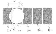
図1に、溶媒制御装置100の一例を上面から見た図を示す。図2に、溶媒制御装置100の一例の側面の断面図を示す。 FIG. 1 shows a view of an example of the solvent control device 100 as viewed from above. FIG. 2 shows a side sectional view of an example of the solvent control device 100.
図1及び図2に示す溶媒制御装置100は、基板204と、複数の電極201と、誘電体205と、撥水膜206とを備える。なお、図1では、誘電体205及び撥水膜206を省略している。実際は、少なくとも複数の電極201の上に、誘電体205及び撥水膜206が配置されている。
The solvent control apparatus 100 shown in FIGS. 1 and 2 includes a
溶媒制御装置100は、複数の電極201に電圧を印加することで、撥水膜206の上に配置される溶媒203の位置を制御する。以下、各構成について説明する。
The solvent control apparatus 100 controls the position of the
<基板204>
基板204は、公知の絶縁性を有する材料が用いられる。絶縁性を有する材料の例は、ガラス、サファイアなどである。
<
A known insulating material is used for the
基板204として、導電性を有する材料、若しくは、シリコン又は金属を含む半導体材料の上に、SiO2、Al2O3、又は高分子材料などの絶縁性材料を被覆した基板を用いてもよい。
As the
<電極201>
複数の電極201は、後述する誘電体205の内部に配置される。又は、複数の電極201は、基板204の上に配置され、かつ、上部を誘電体205が覆うように配置される。
<Electrode 201>
The plurality of
図2に示すように、複数の電極201のそれぞれは、互いに離れた位置に配置される。2つの電極201の間の距離は、電極201の幅より小さい。2つの電極201の間の距離の例は、1mm以下であることが望ましい。複数の電極201におけるそれぞれの電極を、電極201a、電極201b、電極201c、電極201d、電極201eとも表記する。電極201a、電極201b、電極201c、電極201d、電極201eを総称して、電極201とも表記する。
As shown in FIG. 2, each of the plurality of
複数の電極201は、電圧が印加される。図1及び図2に示すように、例えば、複数の電極201のそれぞれには、電極配線202が電気的に接続されている。例えば、電極201a、電極201b、電極201c、電極201d、電極201eに、電極配線202a、電極配線202b、電極配線202c、電極配線202d、電極配線202eのそれぞれが、電気的に接続されている。
A voltage is applied to the plurality of
電源(電圧印加部)207は、電極配線202を介して、複数の電極201の少なくとも1つに電圧を印加することで、溶媒203の位置を制御する。詳細は後述する。
The power source (voltage application unit) 207 controls the position of the
電極201は、電気伝導性を有する公知の材料を用いることができる。電極201の材料の例は、Au、Pt、Cu、Al、及びAgから選択される少なくとも1種類の金属である。
For the
また、溶媒制御装置100を表示装置などに用いることにより、光透過性を有する電極が必要な場合には、電極201として、ITO(Indium Tin Oxide)又はZnOを含む透明導電性材料を用いることが望ましい。
When the solvent control device 100 is used for a display device or the like and an electrode having optical transparency is required, a transparent conductive material containing ITO (Indium Tin Oxide) or ZnO is used as the
また、電極201の材料として、Cr又はTiなどの用いることにより、電極201と、基板204又は誘電体205との密着性を向上させることができる。
In addition, by using Cr or Ti as the material of the
電極201は、蒸着法又はスパッタ法などの公知の成膜方法を用いることにより、形成され得る。
The
電極201は、0.01μm以上2μm以下の厚みを有することが望ましい。
The
例えば、基板204の上に、2μmよりも大きい厚みを有する電極201を形成した場合、基板204に表面における、電極201が形成されている領域の高さと、電極201が形成されていない領域の高さとの差が大きい。その結果、誘電体205及び撥水膜206を形成する際に、誘電体205及び撥水膜206の中で高さの異なる領域が形成される可能性があるため、溶媒203の移動させる際に影響ができる可能性がある。
For example, when the
0.01μmよりも小さい厚みを有する電極201は、電気抵抗が高くなり、電極201及び電極配線202の電気抵抗が高くなる。つまり、電圧が印加される部分(電極201及び電極配線202)の電気抵抗が高くなるため、電圧印加部207から印加した電圧が損失するため、電極201に所望の電圧を印加することが難しくなる。
The
<誘電体205>
誘電体205は、電極201の上に配置される。また、誘電体205は、基板204の上にも配置されても良い。誘電体205は、公知の絶縁材料を用いることができる。誘電体205の例は、高分子化合物、無機化合物の各種酸化物、複合酸化物、又は窒化物などの絶縁材料である。
<
The dielectric 205 is disposed on the
電極201に電圧を印加された場合において、誘電体205は、大きい静電容量を有することが望ましい。よって、誘電体205は、1μm以下の厚みを有する膜を形成することが可能な誘電体材料、又は高い比誘電率を有する材料を用いることができる。
When a voltage is applied to the
誘電体205が高分子化合物で構成される場合には、ディッピング法、スプレーコート法、又はスピンコート法などの公知の方法を用いて、誘電体205を形成することができる。誘電体205が無機化合物で構成される場合には、スパッタ法、スプレーコート法、又はスピンコート法などの公知の方法を用いて、誘電体205を形成することができる。 In the case where the dielectric 205 is made of a polymer compound, the dielectric 205 can be formed using a known method such as a dipping method, a spray coating method, or a spin coating method. In the case where the dielectric 205 is made of an inorganic compound, the dielectric 205 can be formed using a known method such as a sputtering method, a spray coating method, or a spin coating method.
<撥水膜206>
誘電体205の上に配置される。撥水膜の材料の例は、ポリテトラフルオロエチレン(polytetrafluoroethylene:PTFE)又はAF1600(デュポン社製)などフルオロアルキル鎖を有する化合物である。
<
It is disposed on the dielectric 205. An example of the material of the water-repellent film is a compound having a fluoroalkyl chain such as polytetrafluoroethylene (PTFE) or AF1600 (manufactured by DuPont).
一般的に、撥水膜206は、フルオロアルキル鎖を有することにより、高い撥水性能を有する。
In general, the
フルオロアルキル鎖を有する化合物のうち、シランカップリング剤を有する化合物は、誘電体205とカップリング反応することで共有結合するため、誘電体205と撥水膜206との剥離が防止できるため、望ましい。
Among compounds having a fluoroalkyl chain, a compound having a silane coupling agent is desirable because it can be covalently bonded by a coupling reaction with the dielectric 205, thus preventing peeling of the dielectric 205 and the
誘電体205とシランカップリングが可能なフルオロアルキル鎖を有する化合物の例は、トリフルオロプロピルトリメトキシシラン、パーフルオロオクチルトリメトキシシラン、パーフルオロデシルトリメトキシシラン、パーフルオロオクチルトリクロロシラン、パーフルオロデシルトリクロロシラン、サイトップ(登録商標)(旭ガラス製)、又はオプツール(ダイキン工業製)である。 Examples of the compound having a fluoroalkyl chain capable of silane coupling with dielectric 205 are trifluoropropyltrimethoxysilane, perfluorooctyltrimethoxysilane, perfluorodecyltrimethoxysilane, perfluorooctyltrichlorosilane, perfluorodecyl. It is trichlorosilane, Cytop (registered trademark) (manufactured by Asahi Glass), or OPTOOL (manufactured by Daikin Industries).
撥水膜206は、その表面上で溶媒を動作させるため、溶媒に対して付着力が弱いほうが望ましい。より具体的な一例は、溶媒203に対して、滑落角が30°以下である。
Since the
<溶媒203>
溶媒203の例は、アミド、グリコール、グリセリン、アミノアルコール、ヒドロキシアミン、及び多価アルコールから選択される少なくとも1種類を含む材料である。
<Solvent 203>
An example of the solvent 203 is a material including at least one selected from amide, glycol, glycerin, aminoalcohol, hydroxyamine, and polyhydric alcohol.
溶媒203の具体的な例は、ホルムアミド、エチレングリコールモノエチルエーテル、及びテトラブロモエタンから選択される少なくとも1つを含む。 Specific examples of the solvent 203 include at least one selected from formamide, ethylene glycol monoethyl ether, and tetrabromoethane.
溶媒203は、3.1(mN/m)以上28.8(mN/m)以下の極性力成分を有する。 The solvent 203 has a polar force component of 3.1 (mN / m) or more and 28.8 (mN / m) or less.
より望ましくは、ホルムアミド、エチレングリコールモノエチルエーテルから選択される少なくとも1つを含み、かつ、極性力成分が3.1(mN/m)以上28.8(mN/m)以下である。 More desirably, it contains at least one selected from formamide and ethylene glycol monoethyl ether, and the polar force component is 3.1 (mN / m) or more and 28.8 (mN / m) or less.
さらに望ましくは、ホルムアミド、エチレングリコールモノエチルエーテルから選択される少なくとも1つを含み、かつ、極性力成分が3.1(mN/m)以上22.0(mN/m)以下である。 More preferably, it contains at least one selected from formamide and ethylene glycol monoethyl ether, and the polar force component is 3.1 (mN / m) or more and 22.0 (mN / m) or less.
実施例において、上述の具体的な内容を詳細に説明する。 In the embodiment, the specific contents described above will be described in detail.
なお、ホルムアミドは、所定以上に高い極性力成分、及び高い沸点を有することにより、エレクトロウェッティングによる液滴動作が安定して起きるので、特に好ましく用いることができる。 Formamide can be used particularly preferably because it has a polar force component higher than a predetermined value and a high boiling point, so that droplet operation by electrowetting occurs stably.
なお、エチレングリコールモノエチルエーテルは、所定以上の極性力成分を有し、かつ、融点が低く沸点が高いことから、特に低温動作が必要なエレクトロウェッティングによる液滴動作において好ましく用いることができる。 In addition, ethylene glycol monoethyl ether has a polar force component of a predetermined value or more and has a low melting point and a high boiling point. Therefore, ethylene glycol monoethyl ether can be preferably used in a droplet operation by electrowetting that requires a low temperature operation.
<溶媒制御方法>
次に、図3A〜図3Dを用いて、溶媒制御装置100における液滴制御方法を説明する。
<Solvent control method>
Next, a droplet control method in the solvent control apparatus 100 will be described with reference to FIGS. 3A to 3D.
図3A〜図3Dは、図1と同様に、誘電体205及び撥水膜206を省略しているが、実際は、電極201の上に、誘電体205及び撥水膜206が配置されている。
3A to 3D, the dielectric 205 and the
<図3A>
図3Aに示すように、撥水膜206の上に、溶媒203を配置する。溶媒203は、少なくとも2つの電極201の上に位置する。図3Aにおいては、溶媒203は、電極201a及び電極201bの上に位置する。
<FIG. 3A>
As shown in FIG. 3A, a solvent 203 is disposed on the
<図3B>
図3Aの状態から電極201bのみに電圧が印加されるように、電圧を印加する。例えば、電極201bが、図示しない電極配線202b及び電圧印加部207と電気的に接続されている場合には、電圧印加部207により電極配線202bを介して電極201bに電圧を印加する。溶媒203のうち電極201bの上に位置する部分は、濡れ性の変化により接触角が小さくなり、撥水膜206との接触面積が拡大する。その結果、溶媒203は、現在の位置から電極201bの上方に向かって、移動する。
<FIG. 3B>
A voltage is applied so that a voltage is applied only to the
具体的には、図3Bに示すように、矢印Aの方向に、溶媒203は移動する。 Specifically, as shown in FIG. 3B, the solvent 203 moves in the direction of arrow A.
<図3C>
図3Bの状態から電極201cのみに電圧が印加されるように、電圧を印加する。その結果、図3Cに示すように、矢印Aの方向に、溶媒203は移動する。
<FIG. 3C>
A voltage is applied so that a voltage is applied only to the
なお、電極201b及び電極201cに対して、電圧を印加しても良い。電極201b及び電極201cの両方に電圧を印加した後に、電極201cのみに電圧を印加することにより、図3Cに示すように、溶媒203を電極201cの上方に移動させることができる。
Note that a voltage may be applied to the
<図3D>
図3Cの状態から電極201cのみに電圧が印加されるように、電圧を印加する。その結果、図3Dに示すように、矢印Aの方向に、溶媒203は移動する。
<FIG. 3D>
A voltage is applied so that a voltage is applied only to the
このように、溶媒203の少なくとも一部が上部に位置する電極201に電圧を印加することにより、その電極201の上部に位置する溶媒203の濡れ性が変化する。その結果、溶媒203は、撥水膜206の上で、位置が移動する。
As described above, when a voltage is applied to the
溶媒203を図3A〜図3Dに示す矢印Aの方向だけではなく、電圧を電極の位置を制御することで、矢印Aの反対方向にも溶媒203の位置を移動(制御)することができる。 The position of the solvent 203 can be moved (controlled) not only in the direction of the arrow A shown in FIGS. 3A to 3D but also in the opposite direction of the arrow A by controlling the position of the electrode with the voltage.
以下、実施例により、本開示をより詳細に教示する。 The following examples teach the present disclosure in more detail.
(実施例1)
基板204として、ガラス基板を準備した。
Example 1
A glass substrate was prepared as the
ガラス基板上に、フォトリソグラフィを用いて、クロム及び金からなる電極201及び電極配線202を形成した。
An
具体的には、説明する。ガラス基板の上面全体に、クロム及び金を蒸着した。クロム及び金の上面にレジストを塗布した。レジストを塗布した後に、フォトマスクを用いて、露光した。露光後、レジストを除去し、エッチングすることで、クロム及び金を所望の形状に形成した。 Specifically, it will be described. Chromium and gold were deposited on the entire top surface of the glass substrate. A resist was applied to the upper surface of chrome and gold. After applying the resist, exposure was performed using a photomask. After exposure, the resist was removed and etched to form chromium and gold in desired shapes.
図1に示すように、電極201及び電極配線202の形状を形成した。電極201は、幅方向に0.5mmであり、縦方向3mmであった。ここで、幅方向とは、図1に示す左右の方向であり、後述する溶媒203が移動する方向である。縦方向は、幅方向に対して、垂直な方向である。幅方向に、40個の電極201が並ぶように形成された。各電極201の間は、50μmであった。40個の電極201は、幅方向に41mmの長さを有していた。
As shown in FIG. 1, the shape of the
誘電体205として、スパッタ法を用いて、ガラス基板と、クロム及び金からなる電極201及び電極配線202との上に、150nmの厚みを有するSiO2を形成した。
As the dielectric 205, SiO 2 having a thickness of 150 nm was formed on the glass substrate, the
撥水膜206として、スピンコート法を用いて、SiO2の上に、アモルファスフッ素化高分子薄膜(CYTOP(登録商標)旭硝子(株)製)を形成した。撥水膜206の膜厚はおよそ2μmであった。
As the
溶媒203は、ホルムアミドを用いた。溶媒203の量は、3μL、5μL、及び10μLの3種類であった。 As the solvent 203, formamide was used. The amount of the solvent 203 was three types: 3 μL, 5 μL, and 10 μL.
ホルムアミドを撥水膜206の上に滴下した後、電極配線202を介して、電極201に電圧150Vを印加して、溶媒203が動くか否かについて、実験を行った。
After formamide was dropped on the water-
ホルムアミドを撥水膜206の上に滴下と同時に、電極201への電圧の印加と、電圧を印加する電極201の切替(以下、電圧印加の切替とも表記する。)を開始した。0.1秒ごとに、各電極201への電圧印加を切替えた。4秒間で、40個の電極201の端から端まで電圧が印加される条件とし、4秒ごとに電圧の印加方向を逆になるようにして、溶媒203が4秒ごとに左右に往復動作する条件とした。溶媒203の滴下直後、滴下から5分後、滴下から10分後のそれぞれの時刻に、ホルムアミドが動作するか否かの実験を行った。
At the same time when formamide was dropped onto the water-
(実施例2)
溶媒203として、エチレングリコールモノエチルエーテルを用いた以外は、実施例1と同様に実験が行われた。表1に、実験結果を示す。
(Example 2)
The experiment was performed in the same manner as in Example 1 except that ethylene glycol monoethyl ether was used as the solvent 203. Table 1 shows the experimental results.
(実施例3)
溶媒として、テトラブロモエタン(Tetrabromoethane:TBE)を用いたこと以外は実施例1と同様に実験が行われた。表1に、実験結果を示す。
(Example 3)
The experiment was performed in the same manner as in Example 1 except that tetrabromoethane (TBE) was used as the solvent. Table 1 shows the experimental results.
(比較例1)
溶媒として、水を用いたこと以外は、実施例1と同様に実験が行われた。表1に、実験結果を示す。
(Comparative Example 1)
The experiment was performed in the same manner as in Example 1 except that water was used as the solvent. Table 1 shows the experimental results.
(比較例2)
溶媒として、エタノールを用いたこと以外は、実施例1と同様に実験が行われた。表1に、実験結果を示す。
(Comparative Example 2)
The experiment was performed in the same manner as in Example 1 except that ethanol was used as the solvent. Table 1 shows the experimental results.
(比較例3)
溶媒として、非極性溶媒のn−ヘキサデカンを用いたこと以外は、実施例1と同様に実験が行われた。表1に、実験結果を示す。
(Comparative Example 3)
The experiment was performed in the same manner as in Example 1 except that n-hexadecane, which is a nonpolar solvent, was used as the solvent. Table 1 shows the experimental results.
<表1の実験結果>
表1に、実施例1から3、及び比較例1から3の実験結果を示す。
<Experimental results in Table 1>
Table 1 shows the experimental results of Examples 1 to 3 and Comparative Examples 1 to 3.

表1に示すように、実施例1及び実施例2の溶媒を用いた場合、溶媒の体積及び時刻に依存せず、溶媒は動作した。なお、本実施例において、溶媒が動作したか否かは、溶媒203がその時刻を過ぎて最初に動作方向が切り替わった場所を起点に、4秒経過した後、20mm以上動作したものを「動作する」と判断し、動作が20mmに満たないものを「動作しない」と判断した。溶媒が動作したか否かを判断できる方法としては、公知の方法を用いても同様の結果が得られると考えられる。 As shown in Table 1, when the solvents of Example 1 and Example 2 were used, the solvent operated regardless of the volume and time of the solvent. In this embodiment, whether or not the solvent has operated is determined by determining whether or not the solvent 203 has operated for 20 mm or more after 4 seconds have elapsed since the time when the operation direction was switched first after that time. When the operation is less than 20 mm, it was determined that “does not work”. It is considered that the same result can be obtained by using a known method as a method for determining whether or not the solvent has been operated.
実施例3のTBEは、3μLで、滴下直後、滴下から5分後、及び滴下から10分後の時に、液滴は動作した。また、実施例3のTBEは、5μLで、滴下直後、滴下から5分後、及び滴下から10分後の時に、液滴は動作した。 The TBE of Example 3 was 3 μL, and the droplets operated immediately after dropping, 5 minutes after dropping, and 10 minutes after dropping. The TBE of Example 3 was 5 μL, and the droplet operated immediately after dropping, 5 minutes after dropping, and 10 minutes after dropping.
しかし、TBEが5μLで、かつ、滴下直後、滴下から5分後、及び滴下から10分後の時、及びTBEが10μLで、滴下直後、滴下から5分後、及び滴下から10分後の時は、TBEは動作しなかった。5μL及び10μLを有するTBEは、電圧が印加された時に、濡れ性が変化する様子は観察されたが、動かなかった。 However, when TBE is 5 μL and immediately after dropping, 5 minutes after dropping, and 10 minutes after dropping, and when TBE is 10 μL, immediately after dropping, 5 minutes after dropping, and 10 minutes after dropping. TBE did not work. TBEs with 5 μL and 10 μL were observed to change wettability when voltage was applied, but did not move.
比較例1に水は、いずれの体積においても、滴下直後は、動作した。しかし、滴下直後から水は蒸発を始め、水の体積が減少した。滴下から5分後には、3μL及び5μLの体積を有する水は蒸発し、およそ全ての水がなくなったため、動作しないと判断した。10μLの体積を有する水の場合は、5分後に数μLに満たない体積となり、動作しない状態となった。同じ体積にもかかわらず数μLで動作しなかったのは、水が蒸発したあとに撥水膜206上に汚れ(又は水垢)が付着したためと考えられる。比較例1の水は、いずれの体積においても10分後には水がなくなり、動作しないと判断した。
In Comparative Example 1, water operated immediately after dropping in any volume. However, water started to evaporate immediately after dropping, and the volume of water decreased. Five minutes after the dropping, the water having a volume of 3 μL and 5 μL was evaporated, and it was judged that it did not operate because almost all of the water was lost. In the case of water having a volume of 10 μL, the volume became less than several μL after 5 minutes, and the device became inoperative. The reason why the device did not operate at several μL despite the same volume is thought to be that dirt (or scale) adhered to the water-
比較例2のエタノールは、いずれの体積及び時間においても、動作しなかった。電圧を印加した際、電極の上で、エタノールの濡れ性が変化する様子が確認できたが、動かなかった。これは、エタノールの極性力成分が小さいためと考えられる。また、いずれの体積を有するエタノールは、滴下から5分経過後、又は10分経過後に、蒸発した。 The ethanol of Comparative Example 2 did not work at any volume and time. When voltage was applied, it was confirmed that ethanol wettability changed on the electrode, but it did not move. This is probably because ethanol has a small polar force component. In addition, ethanol having any volume was evaporated after 5 minutes or 10 minutes from dropping.
比較例3のn−ヘキサデカンは、いずれの体積及び時間においても、動作しなかった。電圧を印加した状態でも、n−ヘキサデカンの濡れ性が変化した様子は確認できず、n−ヘキサデカンは動作しなかった。 The n-hexadecane of Comparative Example 3 did not operate at any volume and time. Even when a voltage was applied, it was not possible to confirm a change in the wettability of n-hexadecane, and n-hexadecane did not operate.
以上の結果から、実施例1から実施例3では、溶媒を滴下から所定時間後でも、溶媒が動作するのに対して、比較例1から3では、溶媒を滴下から所定時間後は、動作しなかった。言い換えると、ホルムアミド、エチレングリコールモノエチルエーテル、又はTBEを溶媒として用いることにより、溶媒を滴下から所定時間後でも、溶媒が動作することがわかった。 From the above results, in Examples 1 to 3, the solvent operates even after a predetermined time from the dropping of the solvent, whereas in Comparative Examples 1 to 3, the solvent operates after the predetermined time from the dropping of the solvent. There wasn't. In other words, by using formamide, ethylene glycol monoethyl ether, or TBE as a solvent, it was found that the solvent operates even after a predetermined time from the dropping of the solvent.
さらに、実施例1及び2は、溶媒の体積が大きい場合でも、溶媒が動作した。言い換えると、ホルムアミド、又はエチレングリコールモノエチルエーテルを溶媒として用いることにより、溶媒の体積が大きい場合でも、溶媒が動作することがわかった。 Furthermore, in Examples 1 and 2, the solvent operated even when the volume of the solvent was large. In other words, it has been found that by using formamide or ethylene glycol monoethyl ether as a solvent, the solvent operates even when the volume of the solvent is large.
次に、実施例4及び5により、ホルムアミド及びエチレングリコールモノエチルエーテルを混合した場合でも同様に効果が得られるか否かについて、実験を行った。 Next, according to Examples 4 and 5, an experiment was conducted to determine whether or not the same effect can be obtained even when formamide and ethylene glycol monoethyl ether are mixed.
(実施例4)
電極201及び電極配線202の材料は、ITOを用いた。
Example 4
ITO was used as the material of the
基板上に、電極201及び電極配線202を形成した。
An
誘電体205として、スパッタ法により、ガラス基板と、ITOからなる電極201及び電極配線202との上に、150nmの厚みを有するSiO2を形成した。
As the dielectric 205, SiO 2 having a thickness of 150 nm was formed on the glass substrate, the
撥水膜206として、スピンコートにより、SiO2の上に、およそ2μmの厚みを有するCYTOP(登録商標)旭硝子(株)製)を塗布した。
As the
実施例3の溶媒203として、ホルムアミド及びエチレングリコールモノエチルエーテルを混合した溶媒を用いた。表2に示すように、具体的な比率は、ホルムアミドが36.5%であり、エチレングリコールモノエチルエーテルが63.5%であった。混合割合は体積分率を示している。 As the solvent 203 of Example 3, a solvent in which formamide and ethylene glycol monoethyl ether were mixed was used. As shown in Table 2, the specific ratio was 36.5% for formamide and 63.5% for ethylene glycol monoethyl ether. The mixing ratio indicates the volume fraction.
10μLの溶媒203を撥水膜206の上に滴下した直後、及び滴下から30分後のそれぞれの時刻に、溶媒が動作するか否かの実験を行った。実験環境は、大気中であった。表3に、実験結果を示す。
An experiment was conducted to determine whether or not the solvent operates immediately after dropping 10 μL of the solvent 203 on the water-
(実施例5)
溶媒として、ホルムアミド及びエチレングリコールモノエチルエーテルの混合比率が異なること以外は、実施例4と同様に実験が行われた。表2に示すように、具体的な比率は、ホルムアミドが90.7%であり、エチレングリコールモノエチルエーテルが9.3%であった。混合割合は体積分率を示している。
(Example 5)
The experiment was performed in the same manner as in Example 4 except that the mixing ratio of formamide and ethylene glycol monoethyl ether was different as the solvent. As shown in Table 2, the specific ratio was 90.7% for formamide and 9.3% for ethylene glycol monoethyl ether. The mixing ratio indicates the volume fraction.
次に、実施例6により、ホルムアミド及び水を混合した場合でも同様に効果が得られるか否かについて、実験を行った。表3に、実験結果を示す。 Next, an experiment was conducted on whether or not the effect was obtained in the same manner as in Example 6 even when formamide and water were mixed. Table 3 shows the experimental results.
(実施例6)
溶媒として、水及びホルムアミドの混合比率を用いた以外は、実施例3と同様に実験が行われた。具体的な比率は、水が20%であり、ホルムアミドが80%であった。混合割合は体積分率を示している。
(Example 6)
The experiment was performed in the same manner as in Example 3 except that the mixing ratio of water and formamide was used as the solvent. The specific ratio was 20% for water and 80% for formamide. The mixing ratio indicates the volume fraction.
なお、実施例4から6に用いた溶媒のそれぞれの材料は、JIS K6768に定められている表面張力30mN/m、40mN/m、50mN/m、60mN/mを有する材料に相当する。表3に、実験結果を示す。 In addition, each material of the solvent used in Examples 4 to 6 corresponds to a material having a surface tension of 30 mN / m, 40 mN / m, 50 mN / m, or 60 mN / m as defined in JIS K6768. Table 3 shows the experimental results.
表2に、実施例4から6の具体的な比率を示す。 Table 2 shows specific ratios of Examples 4 to 6.
<表3の実験結果>
実施例4から6に加えて、実施例2についても、10μLの溶媒203を撥水膜206の上に滴下した直後、及び滴下から30分後のそれぞれの時刻に、溶媒が動作するか否かの実験を行った。表3に、実験結果を示す。
<Experimental results in Table 3>
In addition to Examples 4 to 6, also in Example 2, whether or not the solvent operates immediately after dropping 10 μL of the solvent 203 on the water-
実施例2、及び4から6の溶媒に対する実験結果によると、滴下した直後、及び滴下から30分後のそれぞれの時刻で、溶媒が動作することがわかった。電極201をITOとで構成した場合、実施例1よりも電極201の抵抗は高くなる。つまり、電圧の印加の際には不利な条件となるが、実施例1の場合と溶媒の動作に変化はなく、実施例1及び実施例2における電極201の種類が異なることに依存した、溶媒203の動作への影響は少ないと考えられる。
According to the experimental results for the solvents of Examples 2 and 4 to 6, it was found that the solvent was operated immediately after the dropping and at each
なお、実施例6は、滴下から30分後の時刻において、溶媒の体積が減少していることが観察された。溶媒に含まれる水が蒸発したと考えられる。溶媒に含まれる水が蒸発した場合でも、実施例6の溶媒は動作した。
In Example 6, it was observed that the volume of the solvent decreased at the
実施例4及び5の結果から、ホルムアミド及びエチレングリコールモノエチルエーテルの混合物を溶媒に用いた時に、電圧を印加することにより溶媒が動作することがわかった。
この結果から、実施例1から3の材料の混合物は、電圧が印加されることにより、溶媒は動作すると考えられる。
From the results of Examples 4 and 5, it was found that when a mixture of formamide and ethylene glycol monoethyl ether was used as the solvent, the solvent operated by applying a voltage.
From this result, it is considered that the solvent of the mixture of the materials of Examples 1 to 3 operates when a voltage is applied.
実施例6の結果から、エチレングリコールモノエチルエーテル及び水の混合物を溶媒として用いた時、滴下から30分後でも、電圧を印加することにより溶媒が動作することがわかった。溶媒を水で構成した場合、滴下から30分後において、電圧を印加することにより溶媒は動作しない。つまり、実施例1から3の材料と、溶媒として用いられた場合に動作しない材料との混合物は、滴下から30分後でも、電圧を印加することにより溶媒が動作すると考えられる。溶媒として用いられた場合に動作しない材料を混合する割合は、所定以下であることが望ましいと考えられる。所定より多い割合で、溶媒として用いられた場合に動作しない材料を混合することで、溶媒が動作しづらくなると考えられるからである。実施例6の結果から、所定の割合の例は、20%である。
From the results of Example 6, it was found that when a mixture of ethylene glycol monoethyl ether and water was used as a solvent, the solvent was operated by applying a voltage even 30 minutes after dropping. When the solvent is composed of water, the solvent does not operate by applying a
表4に、上述の実施例1〜6、及び比較例1〜3について、表面張力(γ)と極性力成分(γP)とを示す。また、表4に、溶媒を滴下した直後、及び滴下から30分後に、電圧を印加することにより、溶媒が動作したか否かを示した。 Table 4 shows the surface tension (γ) and the polar force component (γ P ) for Examples 1 to 6 and Comparative Examples 1 to 3 described above. Table 4 shows whether the solvent was operated by applying a voltage immediately after dropping the solvent and 30 minutes after dropping.
溶媒の体積は、3μLであった。実施例1〜3及び比較例1〜3については、表1の結果から、滴下から30分後に溶媒が動作するか否かの結果を追加している。実施例1〜3及び比較例1〜3の滴下から30分後の結果は、滴下から10分後の結果と同様であった。
The solvent volume was 3 μL. For Examples 1 to 3 and Comparative Examples 1 to 3, the result of Table 1 adds the result of whether or not the solvent operates 30 minutes after dropping. The
極性力成分の算出方法を説明する。(式1)に拡張Fowkes式を示す。表面張力(γ)は、(式2)に示される分散成分(γd)、極性成分(γp)、水素結合成分(γh)の和として表される。極性力成分は、極性成分と水素結合成分との和で表される。(式1)と(式2)とを用いて、γpを算出した。 A method for calculating the polar force component will be described. (Expression 1) shows an extended Fowkes expression. The surface tension (γ) is expressed as the sum of the dispersion component (γ d ), the polar component (γ p ), and the hydrogen bond component (γ h ) shown in (Equation 2). The polar force component is represented by the sum of the polar component and the hydrogen bond component. Γ p was calculated using (Equation 1) and (Equation 2).
ここで、cosθは、接触角を示す。γSは、撥水膜の表面張力を示す。γS dは、撥水膜の分散成分を示す。γS pは、撥水膜の極性成分を示す。γS hは、撥水膜の水素結合成分を示す。γLは、溶媒の表面張力を示す。γL dは、溶媒の分散成分を示す。γL pは、溶媒の極性成分を示す。γL hは、溶媒の水素結合成分を示す。本実施例の溶媒の極性力成分)は、溶媒の極性成分と溶媒の水素結合成分との和で表される。 Here, cos θ represents a contact angle. γ S indicates the surface tension of the water repellent film. γ S d represents a dispersed component of the water-repellent film. γ S p represents a polar component of the water repellent film. γ S h represents a hydrogen bond component of the water repellent film. γ L indicates the surface tension of the solvent. γ L d represents a dispersed component of the solvent. γ L p represents the polar component of the solvent. γ L h represents a hydrogen bond component of the solvent. The polar force component of the solvent in this example is represented by the sum of the polar component of the solvent and the hydrogen bonding component of the solvent.
接触角計(協和界面化学社製「DM500」)を用いて、溶媒の接触角を測定した。 The contact angle of the solvent was measured using a contact angle meter (“DM500” manufactured by Kyowa Interface Chemical Co., Ltd.).
表面張力(γS)、分散成分(γS d)、極性成分(γS p)、及び水素結合成分(γS h)が既知の撥水膜を2種類用意した。2種類の撥水膜に、表面張力(γL)が既知の溶媒を滴下し、2種類の撥水膜のそれぞれについて、接触角cosθ(つまり、2種類の接触角)を得た。 Two types of water-repellent films with known surface tension (γ S ), dispersion component (γ S d ), polar component (γ S p) , and hydrogen bond component (γ S h ) were prepared. A solvent having a known surface tension (γ L ) was dropped onto the two types of water-repellent films to obtain contact angles cos θ (that is, two types of contact angles) for each of the two types of water-repellent films.
2種類の撥水膜により得られた2つの(式1)と(式2)により、溶媒の極性成分(γL p)と溶媒の水素結合成分(γL h)とを求めた。次に、極性成分(γL p)と水素結合成分(γL h)の和で表される溶媒の極性力成分を算出した。 From the two (Formula 1) and (Formula 2) obtained by the two types of water-repellent films, the polar component (γ L p ) of the solvent and the hydrogen bond component (γ L h ) of the solvent were determined. Next, the polar force component of the solvent represented by the sum of the polar component (γ L p ) and the hydrogen bond component (γ L h ) was calculated.
<表1及び表4の実験結果>
表4に示すように、実施例1から6は、アミド、グリコール、グリセリン、アミノアルコール、ヒドロキシアミン、及び多価アルコールから選択される少なくとも1種類であり、かつ、3.1(mN/m)以上28.8(mN/m)以下の極性力成分を有する。より具体的には、実施例1から6の材料は、ホルムアミド、エチレングリコールモノエチルエーテル、及びテトラブロモエタンから選択される少なくとも1つを含む。これにより、溶媒を滴下して所定時間後においても、溶媒を動作させることができる。
<Experimental results of Table 1 and Table 4>
As shown in Table 4, Examples 1 to 6 are at least one selected from amide, glycol, glycerin, aminoalcohol, hydroxyamine, and polyhydric alcohol, and 3.1 (mN / m) It has a polar force component of 28.8 (mN / m) or less. More specifically, the materials of Examples 1 to 6 include at least one selected from formamide, ethylene glycol monoethyl ether, and tetrabromoethane. Thereby, the solvent can be operated even after a predetermined time since the solvent was dropped.
なお、表4に示すように、実施例3に係るテトラブロモエタンの体積は、3μLの時は、溶媒は動作した。しかし、表1に示すように、テトラブロモエタンの体積の5μL及び10μLの時は、溶媒は動作しなかった。つまり、ホルムアミド、エチレングリコールモノエチルエーテル、及びテトラブロモエタンから選択される少なくとも1つを含み、かつ、極性力成分が3.1(mN/m)以上28.8(mN/m)であっても、溶媒の体積に依存して、溶媒を動作させることができなかった。 In addition, as shown in Table 4, when the volume of tetrabromoethane according to Example 3 was 3 μL, the solvent operated. However, as shown in Table 1, the solvent did not work when the volume of tetrabromoethane was 5 μL and 10 μL. That is, it contains at least one selected from formamide, ethylene glycol monoethyl ether, and tetrabromoethane, and the polar force component is 3.1 (mN / m) or more and 28.8 (mN / m). However, depending on the volume of the solvent, the solvent could not be operated.
実施例3の極性力成分は、3.2(mN/m)であった。一方、実施例2の極性成分は、実施例3の極性力成分とほぼ同様である、3.3(mN/m)であった。しかし、表1に示すように、実施例2の溶媒は、体積に依存せず、溶媒は動作したが、実施例3では、体積に依存して、溶媒の動作する否かに変化があった。つまり、本発明者らは、極性力成分だけではなく、溶媒の材料等に依存して、溶媒が動作するか否かには、違いがあることを見出した。 The polar force component of Example 3 was 3.2 (mN / m). On the other hand, the polar component of Example 2 was 3.3 (mN / m) which is substantially the same as the polar force component of Example 3. However, as shown in Table 1, the solvent of Example 2 did not depend on the volume and the solvent operated, but in Example 3, there was a change in whether or not the solvent operated depending on the volume. . That is, the present inventors have found that there is a difference in whether or not the solvent operates depending on not only the polar force component but also the solvent material or the like.
実施例1、2、4から6のように、ホルムアミド、エチレングリコールモノエチルエーテルから選択される少なくとも1つを含み、かつ、極性力成分が3.1(mN/m)以上28.8(mN/m)以下の場合に、溶媒の体積の依存を低減し、かつ、溶媒を滴下して所定時間後においても、溶媒を動作させることができる
また、実施例6では、滴下から30分後でも溶媒を動作することができたが、溶媒の体積が減少した。この結果は、溶媒は、水を含むことにより、所定以上の極性成分を有することになるが、体積の低減を引き起こしていることを示す。体積が低減することにより、複数の電極の上に配置されることが難しくなる可能性がある。よって、溶媒が滴下された後に、溶媒の体積の低減を抑制することが望ましい。
As in Examples 1, 2, 4 to 6, it contains at least one selected from formamide and ethylene glycol monoethyl ether, and the polar force component is 3.1 (mN / m) or more and 28.8 (mN / M) In the following cases, the dependency of the volume of the solvent is reduced, and the solvent can be operated even after a predetermined time after the solvent is dropped. In Example 6, even after 30 minutes from the dropping, The solvent could be operated but the solvent volume was reduced. This result shows that the solvent has a polar component of a predetermined value or more by containing water, but causes a reduction in volume. By reducing the volume, it may be difficult to arrange on the plurality of electrodes. Therefore, it is desirable to suppress a reduction in the volume of the solvent after the solvent has been dropped.
したがって、実施例1、2、4、及び5のように、ホルムアミド、エチレングリコールモノエチルエーテルから選択される少なくとも1つを含み、かつ、極性力成分が3.1(mN/m)以上22.0(mN/m)以下であることがより望ましい。これにより、溶媒の体積低減を抑制し、かつ、溶媒の体積の依存を低減し、かつ、溶媒を滴下して所定時間後においても溶媒を動作させることができる。実施例1、2、4、及び5の溶媒の体積は、少なくとも3μL以上10μL以下で同様の効果を得られることがわかった。 Therefore, as in Examples 1, 2, 4, and 5, it contains at least one selected from formamide and ethylene glycol monoethyl ether, and the polar force component is 3.1 (mN / m) or more and 22. More preferably, it is 0 (mN / m) or less. Thereby, the volume reduction of the solvent can be suppressed, the dependency on the volume of the solvent can be reduced, and the solvent can be operated even after a predetermined time by dropping the solvent. It was found that the same effects can be obtained when the volume of the solvent in Examples 1, 2, 4, and 5 is at least 3 μL or more and 10 μL or less.
<駆動電圧の結果>
図3に、実施例1〜6で、溶媒を動作できる最低駆動電圧を測定した結果を示す。図3の縦軸は、最低駆動電圧(V)であり、横軸は、溶媒の極性力成分(mN/m)である。
<Results of drive voltage>
In FIG. 3, the result of having measured the minimum drive voltage which can operate | move a solvent in Examples 1-6 is shown. The vertical axis in FIG. 3 is the minimum driving voltage (V), and the horizontal axis is the polar force component (mN / m) of the solvent.
溶媒203を撥水膜に滴下した後、印加電圧を徐々に増加させ、溶媒203が動き始める電圧を、最低駆動電圧とした。 After the solvent 203 was dropped on the water repellent film, the applied voltage was gradually increased, and the voltage at which the solvent 203 started to move was defined as the minimum driving voltage.
図2に示すように、最低駆動電圧は、γPが小さいほど低くなる。よって、低電圧で溶媒を動作させることができるため、γPが小さいことが望ましい。 As shown in FIG. 2, the minimum drive voltage decreases as γ P decreases. Therefore, it is desirable that γ P is small because the solvent can be operated at a low voltage.
<その他の物性>
実施例1のホルムアミドは、比重1.13(g/cm3)であり、沸点は210℃であり、融点は2℃から3℃であり、蒸気圧0.11hPaであった。実施例2のエチレングリコールモノエチルエーテルは、比重0.93(g/cm3)であり、沸点は135℃であり、融点は−70℃であり、蒸気圧は0.5kPaであった。
<Other physical properties>
The formamide of Example 1 had a specific gravity of 1.13 (g / cm 3), a boiling point of 210 ° C., a melting point of 2 ° C. to 3 ° C., and a vapor pressure of 0.11 hPa. The ethylene glycol monoethyl ether of Example 2 had a specific gravity of 0.93 (g / cm 3), a boiling point of 135 ° C., a melting point of −70 ° C., and a vapor pressure of 0.5 kPa.
比較例1の水の比重は1であり、沸点は100℃であり、融点は0℃であり、蒸気圧は23hPaであった。実施例1及び2の材料は、水よりも高い沸点を有し、かつ、低い蒸気圧を有することにより、蒸発しにくく、かつ、体積変化も小さいので、湿度が低いなどの屋外などの環境条件で用いる溶媒に望ましく用いられる。 The specific gravity of water of Comparative Example 1 was 1, the boiling point was 100 ° C., the melting point was 0 ° C., and the vapor pressure was 23 hPa. Since the materials of Examples 1 and 2 have a boiling point higher than that of water and have a low vapor pressure, they are difficult to evaporate and have a small volume change. It is desirably used as a solvent used in the above.
以上のように、本実施形態に係る溶媒は、溶媒を滴下した後に長時間動作させることができるため、バイオチップや屋外などの環境で用いる溶媒制御方法(例えば、部品の搬送など)において、好適に用いられる。 As described above, since the solvent according to this embodiment can be operated for a long time after the solvent is dropped, it is suitable for a solvent control method (for example, transportation of parts) used in an environment such as a biochip or outdoors. Used for.
本開示に係る溶媒制御方法は、安定的に溶媒を制御するために有用であり、特に、屋外環境における溶媒除去又は部品搬送の分野などで活用できる。 The solvent control method according to the present disclosure is useful for stably controlling the solvent, and can be used particularly in the field of solvent removal or component transportation in an outdoor environment.
201、201a、201b、201c、201d、201e 電極
202、202a、202b、202c、202d、202e 電極配線
203 溶媒
204 基板
205 誘電体
206 撥水膜
201, 201a, 201b, 201c, 201d,
Claims (10)
前記溶媒制御装置は、
基板と、
前記基板上に配置される複数の電極と、
前記基板及び前記複数の電極を覆うように配置されている誘電体と、
前記誘電体の上に配置され、かつ、撥水性を有する撥水膜とを備え、
前記複数の電極に電圧を印加することにより、前記撥水膜の上の溶媒の位置を制御し、
前記溶媒は、アミド、グリコール、グリセリン、アミノアルコール、ヒドロキシアミン、多価アルコールのうち少なくとも1つを含み、かつ、3.1(mN/m)以上28.8(mN/m)以下の極性力成分を有する、溶媒制御方法。 A solvent control method for controlling the position of a solvent using a solvent control device,
The solvent control device includes:
A substrate,
A plurality of electrodes disposed on the substrate;
A dielectric disposed to cover the substrate and the plurality of electrodes;
A water-repellent film disposed on the dielectric and having water repellency;
By applying a voltage to the plurality of electrodes, the position of the solvent on the water repellent film is controlled,
The solvent contains at least one of amide, glycol, glycerin, aminoalcohol, hydroxyamine, and polyhydric alcohol, and has a polar power of 3.1 (mN / m) or more and 28.8 (mN / m) or less. A solvent control method comprising a component.
請求項1に記載の溶媒制御方法。 The solvent includes at least one selected from formamide, ethylene glycol monoethyl ether, and tetrabromoethane.
The solvent control method according to claim 1.
請求項1に記載の溶媒制御方法。 The solvent includes at least one selected from formamide and ethylene glycol monoethyl ether.
The solvent control method according to claim 1.
請求項3に記載の溶媒制御方法。 The solvent has a polar force component of 3.1 (mN / m) or more and 22.0 (mN / m) or less,
The solvent control method according to claim 3.
請求項4に記載の溶媒制御方法。 The solvent has a volume of 3 μL or more and 10 μL or less;
The solvent control method according to claim 4.
前記溶媒制御装置は、
基板と、
前記基板上に配置される複数の電極と、
前記基板及び前記複数の電極を覆うように配置されている誘電体と、
前記誘電体の上に配置され、かつ、撥水性を有する撥水膜とを備え、
前記溶媒制御方法は、前記複数の電極に電圧を印加することにより、前記撥水膜の上の溶媒の位置を制御し、
前記溶媒は、アミド、グリコール、グリセリン、アミノアルコール、ヒドロキシアミン、多価アルコールのうち少なくとも1つを含み、かつ、3.1(mN/m)以上28.8(mN/m)以下の極性力成分を有する、溶媒。 A solvent used in a solvent control method for controlling the position of a solvent by a solvent control device,
The solvent control device includes:
A substrate,
A plurality of electrodes disposed on the substrate;
A dielectric disposed to cover the substrate and the plurality of electrodes;
A water-repellent film disposed on the dielectric and having water repellency;
The solvent control method controls the position of the solvent on the water repellent film by applying a voltage to the plurality of electrodes,
The solvent contains at least one of amide, glycol, glycerin, aminoalcohol, hydroxyamine, and polyhydric alcohol, and has a polar power of 3.1 (mN / m) or more and 28.8 (mN / m) or less. A solvent having components.
請求項6に記載の溶媒。 The solvent contains at least one selected from formamide, ethylene glycol monoethyl ether, and tetrabromoethane in a predetermined ratio or more.
The solvent according to claim 6.
請求項6に記載の溶媒。 The solvent includes at least one selected from formamide and ethylene glycol monoethyl ether.
The solvent according to claim 6.
請求項8に記載の溶媒。 The solvent has a polar force component of 3.1 (mN / m) or more and 22.0 (mN / m) or less,
The solvent according to claim 8.
請求項9に記載の溶媒。 The solvent has a volume of 3 μL or more and 10 μL or less;
The solvent according to claim 9.
Priority Applications (1)
| Application Number | Priority Date | Filing Date | Title |
|---|---|---|---|
| PCT/JP2014/002052 WO2014167858A1 (en) | 2013-04-12 | 2014-04-09 | Solvent control method and solvent for electrowetting |
Applications Claiming Priority (2)
| Application Number | Priority Date | Filing Date | Title |
|---|---|---|---|
| JP2013083533 | 2013-04-12 | ||
| JP2013083533 | 2013-04-12 |
Publications (1)
| Publication Number | Publication Date |
|---|---|
| JP2016116248A true JP2016116248A (en) | 2016-06-23 |
Family
ID=56142537
Family Applications (1)
| Application Number | Title | Priority Date | Filing Date |
|---|---|---|---|
| JP2013121520A Pending JP2016116248A (en) | 2013-04-12 | 2013-06-10 | Solvent control method, and solvent for use in solvent control method |
Country Status (1)
| Country | Link |
|---|---|
| JP (1) | JP2016116248A (en) |
Cited By (2)
| Publication number | Priority date | Publication date | Assignee | Title |
|---|---|---|---|---|
| CN112136205A (en) * | 2018-02-28 | 2020-12-25 | 沃尔塔实验室公司 | Initiating Droplet Motion Using Differential Wetting |
| WO2021045000A1 (en) * | 2019-09-02 | 2021-03-11 | 株式会社エンプラス | Droplet removal device and droplet removal method |
-
2013
- 2013-06-10 JP JP2013121520A patent/JP2016116248A/en active Pending
Cited By (4)
| Publication number | Priority date | Publication date | Assignee | Title |
|---|---|---|---|---|
| CN112136205A (en) * | 2018-02-28 | 2020-12-25 | 沃尔塔实验室公司 | Initiating Droplet Motion Using Differential Wetting |
| JP2021515693A (en) * | 2018-02-28 | 2021-06-24 | ヴォルタ ラブズ,インク. | Directing the movement of droplets using differential wetting |
| JP7449233B2 (en) | 2018-02-28 | 2024-03-13 | ヴォルタ ラブズ,インク. | Directing droplet motion using differential wetting |
| WO2021045000A1 (en) * | 2019-09-02 | 2021-03-11 | 株式会社エンプラス | Droplet removal device and droplet removal method |
Similar Documents
| Publication | Publication Date | Title |
|---|---|---|
| WO2014167858A1 (en) | Solvent control method and solvent for electrowetting | |
| Liu et al. | Dielectric materials for electrowetting-on-dielectric actuation | |
| JP4773360B2 (en) | System for manipulating fluids | |
| US7791815B2 (en) | Dielectric coatings for electrowetting applications | |
| US7791814B2 (en) | Optical electrowetting device | |
| Hu et al. | Electrowetting devices with transparent single-walled carbon nanotube electrodes | |
| TWI360244B (en) | Laminated structure, production method of the same | |
| US11325127B2 (en) | Methods for fluid manipulation by electrodewetting | |
| US20180059056A1 (en) | Electrowetting on dielectric device including surfactant containing siloxane group | |
| WO2012108463A1 (en) | Hydrophobic dielectric film for electrowetting | |
| KR20060009295A (en) | Electrowetting Module | |
| US20170356086A1 (en) | Atomic layer deposition-inhibiting material | |
| JP2016153725A (en) | Drive method of droplet transport device | |
| JP4310704B2 (en) | Optical element | |
| JP2016050951A (en) | Concave Fresnel lens and control method of concave Fresnel lens | |
| t Mannetje et al. | Electrically assisted drop sliding on inclined planes | |
| WO2018066527A1 (en) | Composition containing fluorinated polymer, and method for producing substrate having fluorinated polymer film coated thereon | |
| JP2016116248A (en) | Solvent control method, and solvent for use in solvent control method | |
| TWI658536B (en) | Conductor composition ink, laminated wiring member, semiconductor element and electronic device, and manufacturing method of laminated wiring member | |
| JP2000347005A (en) | Variable focus lens device | |
| TW201423153A (en) | Method and apparatus for manufacturing an electrowetting element | |
| Lee et al. | Dielectrically stabilized electrowetting on AF1600/Si3N4/TiO2 dielectric composite film | |
| TWI338790B (en) | Optical device | |
| JP2009076529A (en) | PATTERN FORMING METHOD, WIRING BOARD AND ELECTRONIC DEVICE | |
| Geng et al. | Anti-biofouling droplet manipulation by slippery liquid infused porous surface (SLIPS) integrated with electrowetting and liquid-dielectrophoresis |