JP2016010911A - Ink container and inkjet recording device comprising the same - Google Patents
Ink container and inkjet recording device comprising the same Download PDFInfo
- Publication number
- JP2016010911A JP2016010911A JP2014133622A JP2014133622A JP2016010911A JP 2016010911 A JP2016010911 A JP 2016010911A JP 2014133622 A JP2014133622 A JP 2014133622A JP 2014133622 A JP2014133622 A JP 2014133622A JP 2016010911 A JP2016010911 A JP 2016010911A
- Authority
- JP
- Japan
- Prior art keywords
- ink
- ink pack
- pack
- storage case
- paper
- Prior art date
- Legal status (The legal status is an assumption and is not a legal conclusion. Google has not performed a legal analysis and makes no representation as to the accuracy of the status listed.)
- Pending
Links
Images


Landscapes
- Ink Jet (AREA)
Abstract
Description
本発明は、用紙等の記録媒体にインクを吐出することによって記録を行うインクジェット記録装置に用いられ、インクパックとインクパックを収納する収納ケースを備えるインクコンテナ、及びそれを備えたインクジェット記録装置に関するものである。 The present invention relates to an ink container including an ink pack and a storage case for storing the ink pack, and an ink jet recording apparatus including the ink pack, which is used in an ink jet recording apparatus that performs recording by discharging ink onto a recording medium such as paper. Is.
ファクシミリ、複写機、プリンター等の記録装置は、紙、OHP用シート等の記録媒体に画像を記録するように構成されているが、記録を行う方式により、インクジェット式、ワイヤードット式、サーマル式等に分類することができる。また、インクジェット記録方式は、記録ヘッドが記録媒体上を走査しながら記録を行うシリアル型と、記録装置本体に固定された記録ヘッドにより記録を行うラインヘッド型に分類することができる。 Recording devices such as facsimiles, copiers, and printers are configured to record an image on a recording medium such as paper or an OHP sheet. Depending on the recording method, ink jet, wire dot, thermal, etc. Can be classified. The ink jet recording method can be classified into a serial type in which recording is performed while the recording head scans the recording medium, and a line head type in which recording is performed by a recording head fixed to the recording apparatus main body.
例えばラインヘッド型のインクジェット記録装置は、記録媒体の搬送方向に対し直交する印字領域幅全域に亘って吐出ノズルが所定の間隔で並んでいるラインヘッド型のインクジェットヘッド(記録ヘッド)を色毎に備えている。そして、記録媒体の搬送に合わせて印字位置に対応した吐出ノズルからインクを吐出することにより、記録媒体全体の印字を可能としたものである。 For example, a line head type ink jet recording apparatus uses a line head type ink jet head (recording head) for each color in which ejection nozzles are arranged at predetermined intervals over the entire width of the print area orthogonal to the conveyance direction of the recording medium. I have. The entire recording medium can be printed by discharging ink from the discharge nozzle corresponding to the printing position in accordance with the conveyance of the recording medium.
このようなインクジェット記録装置では、記録ヘッドにインクを供給するために、内部にインクが充填された可撓性のインクパックと、インクパックを収納する収納ケースとを有するインクコンテナが使用される。 In such an ink jet recording apparatus, an ink container having a flexible ink pack filled with ink and a storage case for storing the ink pack is used to supply ink to the recording head.
例えば特許文献1には、インクパックの周縁部に固定用の穴部を形成し、ベース部とカバー部で構成されるケースのベース部にインクパックの穴部に挿入される凸形状部を形成し、カバー部に、ベース部の凸形状部に対応する位置に凸形状部が嵌合方向を長手方向とした長穴形状の凹形状部を備えた記録液収納容器が開示されている。 For example, in Patent Document 1, a fixing hole is formed in the peripheral portion of the ink pack, and a convex shape portion that is inserted into the hole portion of the ink pack is formed in the base portion of the case constituted by the base portion and the cover portion. In addition, a recording liquid storage container is disclosed in which a cover portion is provided with a concave portion having a long hole shape with the fitting direction as a longitudinal direction at a position corresponding to the convex portion of the base portion.
ところで、上述したようなインクコンテナにおいて、インクパックから記録ヘッドへのインク供給を行うと、インクパック内のインクが排出されるにつれ、インクパックの外観形状が膨らんだ状態から次第につぶれて偏平な状態へと変化していく。インクパックがつぶれていく過程において、インクパックが側面の折り目に沿ってつぶれていく場合は、概ね偏平な形状へと推移するが、インクパックがつぶれていく過程で偶然に発生する、折り目とは異なるシワに沿ってつぶれていった場合などにおいて、最終的な形状が偏平とはならず、一部分が盛り上がった形状のままつぶれずに残ってしまうことがある。 By the way, in the ink container as described above, when ink is supplied from the ink pack to the recording head, the outer shape of the ink pack gradually collapses and becomes flat as the ink in the ink pack is discharged. It will change to. If the ink pack collapses along the side crease in the process of collapsing the ink pack, it will transition to a generally flat shape, but what happens to the crease by chance in the process of collapsing the ink pack? In the case of crushing along different wrinkles, the final shape may not be flat, and a part of the shape may rise and remain uncrushed.
インクパックの一部分がつぶれずに残った場合においては、インクパック内に記録ヘッドへ供給できずに残る、無駄になってしまうインクが多くなることが判っている。特に、内部にインクが充填されたインクパックと、インクパックを内包するケースとの2重構造となるインクコンテナの場合、インクパックが外部から見えにくいこともあり、インクパック内のインクが多量に残った状態でインクコンテナを廃棄してしまうという問題点があった。 It has been found that when a part of the ink pack remains without being crushed, more ink is wasted and cannot be supplied to the recording head in the ink pack. In particular, in the case of an ink container having a double structure of an ink pack filled with ink and a case containing the ink pack, the ink pack may be difficult to see from the outside, and a large amount of ink is contained in the ink pack. There was a problem that the ink container was discarded in the state of remaining.
特許文献1の構成では、インクパックの供給口側がベース部とカバー部に挟み込まれ、供給口と反対側の辺部に形成された穴部に凸形状部が挿入されることでインクパックの両端がケースに保持されている。そのため、インクパックがつぶれていく過程でインクパックの変形が規制されてしまい、折り目とは異なる箇所にシワが発生し易くなるおそれがあった。 In the configuration of Patent Document 1, the supply port side of the ink pack is sandwiched between the base portion and the cover portion, and convex portions are inserted into holes formed in the side portion on the opposite side to the supply port, whereby both ends of the ink pack are inserted. Is held in the case. Therefore, the deformation of the ink pack is restricted in the process of collapsing the ink pack, and there is a possibility that wrinkles are likely to occur at a location different from the fold.
本発明は、上記問題点に鑑み、インクパックのつぶれ性を改善することで、インクパックの交換が必要となった際のインクパック内の残インクの量を低減可能なインクコンテナ及びそれを備えたインクジェット記録装置を提供することを目的とする。 In view of the above problems, the present invention includes an ink container that can reduce the amount of ink remaining in an ink pack when the ink pack needs to be replaced by improving the collapseability of the ink pack, and the ink container Another object of the present invention is to provide an ink jet recording apparatus.
上記目的を達成するために本発明の第1の構成は、インクパックと、収納ケースと、を備えたインクコンテナである。インクパックは、可撓性フィルムで形成され、内部にインクを収納する収納部と、該収納部に連通するインク供給口と、を有する。収納ケースは、インクパックを収納する。収納ケースは、インクパックのインク供給口に嵌合する嵌合部と、収納ケースと前記インクパックとの間に連結され、インクパックに嵌合部から離間する方向の付勢力を付与する付勢部材と、を有する。付勢部材は、インクが充填された状態のインクパックを収納ケース内の所定位置に保持するとともに、インクの消費に伴うインクパックの伸びに応じて収縮することによりインクパックへの付勢力の付与を継続する。 In order to achieve the above object, a first configuration of the present invention is an ink container including an ink pack and a storage case. The ink pack is formed of a flexible film, and includes a storage unit that stores ink therein, and an ink supply port that communicates with the storage unit. The storage case stores the ink pack. The storage case is connected between the fitting portion that fits into the ink supply port of the ink pack and the storage case and the ink pack, and the biasing force that applies a biasing force in the direction away from the fitting portion to the ink pack. And a member. The biasing member holds the ink pack filled with ink at a predetermined position in the storage case, and applies a biasing force to the ink pack by contracting according to the expansion of the ink pack as the ink is consumed. Continue.
本発明の第1の構成によれば、インクが充填された状態のインクパックにおいてはインクパックに連結された付勢部材の付勢力によってインクパックの長手方向に張力が加えられるため、インクパックの長手方向への移動が規制され、振動や衝撃によってインクパックが収納ケースの内部で動き回るのを抑制する。また、インクパック内のインクの消費が進んだ状態では、インクパックは所定方向に徐々に伸びていくが、インクパックの長手方向(伸び方向)の一端側においてはインク供給口と嵌合部との嵌合で位置規制するとともに、インクパックの長手方向の他端側においてはインクパックと収納ケースとの間に連結された付勢部材の収縮によりインクパックの長手方向への伸びの影響を吸収することができる。従って、インクパックの自由な変形を規制しない構成となり、インクパックが折り線に沿って平坦状につぶれていくため、インクパックの交換が必要となった際のインクパック内の残インク量を極力低減可能となる。 According to the first configuration of the present invention, in the ink pack filled with ink, tension is applied in the longitudinal direction of the ink pack by the biasing force of the biasing member connected to the ink pack. Movement in the longitudinal direction is restricted, and the ink pack is prevented from moving around inside the storage case due to vibration or impact. In addition, when the ink consumption in the ink pack is advanced, the ink pack gradually extends in a predetermined direction, but at one end side in the longitudinal direction (extension direction) of the ink pack, the ink supply port and the fitting portion In the other end of the ink pack in the longitudinal direction, the impact of the expansion in the longitudinal direction of the ink pack is absorbed by the contraction of the urging member connected between the ink pack and the storage case. can do. Therefore, the free deformation of the ink pack is not restricted, and the ink pack is flattened along the fold line, so that the remaining ink amount in the ink pack when the ink pack needs to be replaced is reduced as much as possible. It can be reduced.
以下、図面を参照しながら本発明の実施形態について説明する。図1は、本発明のインクコンテナ21C〜21Kが搭載されるインクジェット記録装置の一例である、インクジェット式プリンター100の構成を示す図、図2は、図1における第1ベルト搬送部5、記録部9、第2ベルト搬送部12付近の図、図3は、図1に示すプリンター100の第1ベルト搬送部5及び記録部9を上方から見た図である。
Hereinafter, embodiments of the present invention will be described with reference to the drawings. FIG. 1 is a diagram showing a configuration of an
図1に示すように、プリンター100は、プリンター本体1の内部下方に用紙収容部である給紙カセット2aが配置されている。給紙カセット2aの内部には、記録媒体の一例である印字前のカットペーパーなどの用紙Pが所定枚数(例えば500枚程度)積載して収容されている。給紙カセット2aの用紙搬送方向下流側、すなわち図1における給紙カセット2aの右側の上方には給紙装置3aが配置されている。この給紙装置3aにより、用紙Pは図1において給紙カセット2aの右上方に向け、1枚ずつ分離されて送り出される。給紙カセット2aはプリンター本体1の正面側から水平に引き出して用紙Pを補充することが可能である。
As shown in FIG. 1, the
プリンター本体1の右側面外部には手差し給紙トレイ2bが備えられている。手差し給紙トレイ2bには給紙カセット2a内の用紙Pとは異なるサイズの用紙や、厚紙、OHPシート、封筒、ハガキ、送り状のように屈曲した搬送経路を通過するのが困難な記録媒体、1枚ずつ手で送り込みたい記録媒体などが載置される。手差し給紙トレイ2bの用紙搬送方向下流側、すなわち図1における手差し給紙トレイ2bの左側には給紙装置3bが配置されている。この給紙装置3bにより、手差し給紙トレイ2b上の用紙は図1において左方に向け、1枚ずつ分離されて送り出される。
A manual
また、プリンター100はその内部に第1用紙搬送路4aを備えている。第1用紙搬送路4aは、給紙カセット2aに関して言えばその給紙方向である右上方に位置し、手差し給紙トレイ2bに関して言えばその左方に位置する。給紙カセット2aから送り出された用紙Pは第1用紙搬送路4aを通ってプリンター本体1の側面に沿って垂直上方に、手差し給紙トレイ2bから送り出された用紙は略水平左方に向けて搬送される。
Further, the
用紙搬送方向に対し第1用紙搬送路4aの下流端にはレジストローラー対13が備えられている。さらにレジストローラー対13の下流側直近には第1ベルト搬送部5及び記録部9が配置されている。給紙カセット2a(または手差し給紙トレイ2b)から送り出された用紙Pは第1用紙搬送路4aを通ってレジストローラー対13に到達する。レジストローラー対13は用紙Pの斜め送りを矯正しつつ記録部9が実行するインク吐出動作とのタイミングを計り、第1ベルト搬送部5に向かって用紙Pを送り出す。なお、第1用紙搬送路4aには用紙Pを搬送するための搬送ローラー対が適所に設けられている。
A
第1ベルト搬送部5は、第1駆動ローラー6と、第1従動ローラー7とに巻き掛けられた無端状の第1搬送ベルト8を備えている。第1搬送ベルト8は第1駆動ローラー6により図2において反時計回り方向に回転する。レジストローラー対13によって送り出された用紙Pは第1搬送ベルト8の搬送面8a(図2において上面)に保持され、図2の矢印X方向(右方から左方)へと搬送される。なお、第1駆動ローラー6及び第1従動ローラー7に加えて、第1搬送ベルト8に内接する1つ以上のテンションローラーを必要に応じて設けても良い。
The first belt conveyance unit 5 includes an endless
第1搬送ベルト8の内側であって第1搬送ベルト8の搬送面8aの裏側に対向する箇所には第1用紙吸引部30が備えられている。第1用紙吸引部30は、上面に多数の空気吸引用の孔30aが設けられ、内部にはファン30bを備えており、上面から下方に向かって空気を吸引することができる。また、第1搬送ベルト8にも多数の空気吸引用の通気孔(図示せず)が設けられている。上記の構成により、第1ベルト搬送部5は第1搬送ベルト8の搬送面8aに用紙Pを吸着保持しながら搬送する。
A first
記録部9は、ヘッドハウジング10と、ヘッドハウジング10に保持されたラインヘッド11C、11M、11Y、及び11Kを備えている。これらのラインヘッド11C〜11Kは、第1搬送ベルト8の搬送面8aに対して所定の間隔(例えば1mm)が形成されるような高さに支持され、図3に示すように、用紙搬送方向と直交する用紙幅方向(図3の上下方向)に沿って複数(ここでは3個)の記録ヘッド17a〜17cが千鳥状に配列されている。ラインヘッド11C〜11Kは、用紙Pの幅以上の記録領域を有しており、外部コンピューター等から受信した画像データの情報に対応して、第1搬送ベルト8の搬送面8aに吸着保持されて搬送される用紙Pに対して、各色のインクを印字位置に対応したインク吐出ノズル18から吐出する。これにより、用紙Pにはイエロー、マゼンタ、シアン、ブラックの4色のインクが重ね合わされたフルカラー画像が記録される。なお、プリンター100ではモノクロ画像を記録することも可能である。
The recording unit 9 includes a
記録部9の上方にはコンテナ装着部20が配置されている。コンテナ装着部20には、シアン(C)、マゼンタ(M)、イエロー(Y)、ブラック(K)のインクをそれぞれ収容した複数のインクコンテナ21C、21M、21Y、21Kが着脱可能に装着されている。インクコンテナ21C〜21Kは、それぞれ各色のインク供給チューブ23を介してラインヘッド11C〜11Kに連結されており、コンテナ装着部20とラインヘッド11C〜11Kとの高低差により発生するインク圧によってインクコンテナ21C〜21Kから対応する色のインクがラインヘッド11C〜11Kに補充供給される。
A
なお、ここではコンテナ装着部20とラインヘッド11C〜11Kとの高低差によってインクコンテナ21C〜21K内のインクを送液しているが、コンテナ装着部20にインクコンテナ21C〜21K内のインクを送液するための供給ポンプユニットを設けても良い。
Here, the ink in the
また、記録部9は、記録ヘッドの乾燥や目詰まりによるインクの吐出不良を防止するために、長期間停止後の印字開始時は全ての記録ヘッドのインク吐出ノズル18から、また印字動作の合間にはインク吐出量が規定値以下のインク吐出ノズル18から、ノズル内の粘度が高くなったと推測できるインクを吐出するパージを実行して、次の印字動作に備える。
In addition, the recording unit 9 prevents the ink discharge failure due to the drying or clogging of the recording head, from the
なお、記録ヘッド17a〜17cからのインクの吐出方式としては、例えば、図示しないピエゾ素子を用いてインクを押し出すピエゾ方式や、発熱体によって気泡を発生させ、圧力をかけてインクを吐出するサーマルインクジェット方式など、各種方式を適用することができる。 In addition, as a method for ejecting ink from the recording heads 17a to 17c, for example, a piezo method in which ink is ejected using a piezo element (not shown), or a thermal ink jet in which bubbles are generated by a heating element and ink is ejected by applying pressure. Various methods such as a method can be applied.
用紙搬送方向に対し第1ベルト搬送部5の下流側(図1の左側)には第2ベルト搬送部12が配置されている。記録部9にてインク画像が記録された用紙Pは第2ベルト搬送部12へと送られ、第2ベルト搬送部12を通過する間に用紙P表面に吐出されたインクが乾燥される。
A second
第2ベルト搬送部12は、第2駆動ローラー41と、第2従動ローラー42とに巻き掛けられた無端状の第2搬送ベルト40を備えている。第2搬送ベルト40は第2駆動ローラー41により図2において反時計回り方向に回転する。記録部9によって画像が記録され、第1ベルト搬送部5によって矢印X方向へ搬送された用紙Pは第2搬送ベルト40に受け渡され、図2の矢印Z方向へと搬送される。なお、第2駆動ローラー41及び第2従動ローラー42に加えて、第2搬送ベルト40に内接する1つ以上のテンションローラーを必要に応じて設けても良い。
The second
第2搬送ベルト40の内側であって第2搬送ベルト40の搬送面40aの裏側に対向する箇所には第2用紙吸引部43が備えられている。第2用紙吸引部43は、上面に多数の空気吸引用の孔43aが設けられ、内部にはファン43bを備えており、上面から下方に向かって空気を吸引することができる。また、第2搬送ベルト40にも多数の空気吸引用の通気孔(図示せず)が設けられている。上記の構成により、第2ベルト搬送部12は第2搬送ベルト40の搬送面40aに用紙Pを吸着保持しながら搬送する。
A second
用紙搬送方向に対し第2ベルト搬送部12の下流側であってプリンター本体1の左側面近傍にはデカーラー部14が備えられている。第2ベルト搬送部12にてインクが乾燥された用紙Pはデカーラー部14へと送られ、用紙幅方向に並んだ複数のローラーを用いて用紙Pのカールが矯正される。
A
用紙搬送方向に対しデカーラー部14の下流側(図1の上方)には第2用紙搬送路4bが備えられている。デカーラー部14を通過した用紙Pは両面記録を行わない場合、第2用紙搬送路4bから排出ローラー対を介してプリンター100の左側面外部に設けられた用紙排出トレイ15に排出される。
A second
また、第2ベルト搬送部12の下方にはメンテナンスユニット19が配置されている。メンテナンスユニット19は、上述したパージを実行する際に記録部9の下方に移動し、記録ヘッド17のインク吐出ノズル18(図3参照)から吐出されたインクを拭き取り、拭き取られたインクを回収する。
A
プリンター本体1の上部であって記録部9及び第2ベルト搬送部12の上方には両面記録を行うための反転搬送路16が備えられている。両面記録を行う場合には第一面への記録が終了して第2ベルト搬送部12及びデカーラー部14を通過した用紙Pが第2用紙搬送路4bを通って反転搬送路16へと送られる。反転搬送路16へ送られた用紙Pは、続いて第二面の記録のために搬送方向が切り替えられ、プリンター本体1の上部を通過して右側に向かって送られ、第1用紙搬送路4a、及びレジストローラー対13を経て第二面を上向きにした状態で再度第1ベルト搬送部5へと送られる。なお、第2用紙搬送路4b、反転搬送路16には、第1用紙搬送路4aと同様に、用紙Pを搬送するための搬送ローラー対が適所に設けられている。
A
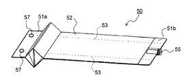
図4は、ラインヘッド11Kにブラックのインクを供給する本発明の第1実施形態に係るインクコンテナ21Kを分解した状態を示す図、図5は、インク充填前のインクパック50の平面図、図6は、インクコンテナ21Kの側面断面図である。インクコンテナ21Kは、内部にインクを収納 したインクパック50と、インクパックを収納する収納ケース60とから構成されている。なお、インクコンテナ21C〜21Yはインクコンテナ21Kと同一の形状及び構成であるため、ここでは説明を省略する。
FIG. 4 is a diagram illustrating a state in which the
インクパック50は、1枚の可撓性フィルムであるラミネートフィルムの両端部(図4〜図6では不図示)を貼り合わせて筒状にした後、筒状の一端をヒートシールして第1シール部51aを形成し、収納部52内にインクを充填した後、筒状の他端をヒートシールして第2シール部51bを形成したものである。インクパック50は、収納部52に厚みを持たせるために収納部52の側面に折り線53に沿ってマチ(折り込み)を入れた、いわゆるガゼット袋である。4方の周縁部のうち第2シール部51bには、収納部52内に連通する円筒状のインク供給口55が取り付けられている。インク供給口55はポリエチレン製であり、先端部の近傍には周方向に沿って環状の溝部55aが形成されている。
The
図4及び図6に示すように、収納部52にインクが充填されたインクパック50は、収納部52の側面に折り込まれたマチが伸びた状態となっている。そのため、インクパック50の長手方向の寸法L1は、収納部52に厚みができる分だけインク充填前のインクパック50の長手方向の寸法Lよりも短くなっている。
As shown in FIGS. 4 and 6, the
また、インクパック50の第1シール部51aには、引っ張りバネ58の一端が係合する2つの係合穴57が形成されている。
The
収納ケース60は、例えばポリスチレン製のベース部70と、カバー部80とから構成されている。ベース部70とカバー部80とは組み合わされて偏平直方体形状の箱体となり、内部にインクパック50が収納される。
The
ベース部70は、方形状の底面部71と、底面部71の周縁に立設された第1周壁部72とを備えている。第1周壁部72には、インクパック50のインク供給口55に形成された溝部55aが嵌合する半円形の第1嵌合部73が形成されている。また、第1嵌合部73の反対側に位置する第1周壁部72の内側には、カバー部80との結合用の2個所の係合部74が形成されている。底面部71には、内周面に雌ネジが形成された2個所のビス穴75と、引っ張りバネ58の他端が係止される2箇所のボス部76とが形成されている。
The
カバー部80は、方形状の上面部81と、上面部81の周縁に立設された第2周壁部82とを備えている。第2周壁部82の第1嵌合部73と対向する位置には、インクパック50のインク供給口55の溝部55aが嵌合する半円形の第2嵌合部83が形成されている。また、第2嵌合部83の反対側に位置する第2周壁部82の内側には、ベース部70の係合部74と係合する2個所の係合爪84が形成されている。上面部81には、2個所のビス挿通穴85と、ベース部70のボス部76が挿入される凹状のボス穴部86が形成されている。
The
ベース部70とカバー部80の組み立てに際しては、先ず、ベース部70の底面部71にインクパック50を配置する。インクパック50は、第1シール部51aに形成された係合穴57に引っ張りバネ58の一端が係合され、引っ張りバネ58の他端がボス部76に係止される。また、第2シール部51bに設けられたインク供給口55の溝部55aがベース部70の第1嵌合部73に嵌合するように配置される。
In assembling the
次に、第2周壁部82と第1周壁部72とが接合するようにカバー部80をベース部70に重ね合わせることにより、底面部71と上面部81とが相対向して配置される。ベース部70の係合部74とカバー部80の係合爪84とを係合するとともに、ボス部76をボス孔部86に挿入することによりベース部70とカバー部80とが水平方向に位置決めされた後、2本のビス90をビス挿通穴85に挿入し、ビス挿通穴85を介してビス穴75に螺入することによりベース部70とカバー部80とが固定される。
Next, the
インクパック50は、第2シール部51bに設けられたインク供給口55の溝部55aがベース部70の第1嵌合部73とカバー部80の第2嵌合部83との間に挟持されるとともに、第1シール部51aに形成された係合穴57とボス部76との間に引っ張りバネ58が連結される。以上のようにして、インクが充填されて収納部52が膨らんだ状態のインクパック50は、第1嵌合部73及び第2嵌合部83、及び引っ張りバネ58によって長手方向の両端部(第1シール部51a及び第2シール部51b)が確実に保持された状態で収納ケース60内に収納される。
In the
従って、輸送中などにインクコンテナ21Kの外部からインクコンテナ21Kに振動や衝撃が加えられた場合でも、収納ケース60の内部でのインクパック50の動きが規制されるため、インクパック50に折り線53以外のシワが生じ難くなる。その結果、インクパック50内のインク量が減少したとき、インクパック50の内圧の低下に応じてインクパック50が折り線53に沿って平坦につぶれることができる。また、ボス部76がボス孔部86に挿入されることで引っ張りバネ58がボス部76から外れるおそれがなくなる。
Therefore, even when vibration or impact is applied to the
ところで、上述したインクコンテナ21C〜を21Kコンテナ装着部20に装着し、インクがラインヘッド11C〜11Kに供給されると、インクパック50内のインク量が減少するにつれ、インクパック50の内圧が低下することでインクパック50は厚み方向にしぼみ、その分だけインクパック50の長手方向の寸法が長くなっていく。
By the way, when the
具体的には、図8及び図9に示すように、インク充填時(図4、図6参照)には伸ばされた状態であった収納部52の側面のマチ(折り込み)が再び折り線53に沿って収納部52の内側に折り込まれ、インクパック50の厚み方向の寸法が小さくなる。その結果、インクパック50の長手方向の寸法L2は、インク充填時の長手方向の寸法L1(図6参照)に比べて長くなる。例えば、インク容量が1Lのガゼット型のインクパック50の場合、インクが充填された状態とインクが空の状態とで2〜3cmの寸法差が生じる。
Specifically, as shown in FIGS. 8 and 9, the gusset (folding) on the side surface of the
このとき、図6に示したインク充填状態でインクパック50の長手方向の両端部(第1シール部51a及び第2シール部51b)を収納ケース60内に固定してしまうと、インクパック50内のインクの減少に伴うインクパック50の伸びを吸収できず、インクパック50が厚み方向に湾曲する。その結果、インクパック50が平坦状につぶれるとともに長手方向の寸法が長くなるというインクパック50の自然な変形を阻害してしまい、インクパック50が折り線53と異なる位置で不規則に変形する原因となる。
At this time, if both end portions (
そこで、本実施形態では、インクパック50の第1シール部51aと収納ケース60のボス部76との間に、インクパック50の伸び方向(長手方向)に沿って伸縮可能な引っ張りバネ58を連結している。この構成により、インクが充填された状態のインクパック50においては係合穴57に連結された引っ張りバネ58の付勢力によってインクパックの長手方向に張力が加えられるため、インクパック50の長手方向への移動が規制され、振動や衝撃によってインクパック50が収納ケース60の内部で動き回らない。従って、インクパックに不規則な折りぐせがつくのを防止することができる。
Therefore, in the present embodiment, a
また、インクコンテナ21C〜21Kがコンテナ装着部20に装着され、インクパック50内のインクの消費が進んだ状態では、インクパック50は長手方向に徐々に伸びていくが、インクパック50の長手方向(伸び方向)の一端側である第2シール部51bにおいてはインク供給口55の溝部と収納ケース60との嵌合で位置規制するとともに、インクパック50の長手方向の他端側である第1シール部51aにおいては係合穴57とボス部76との間に連結された引っ張りバネ58の収縮によりインクパック50の長手方向への伸びの影響を吸収することができる。従って、インクパック50の自由な変形を規制しない構成となり、インクパック50が折り線53に沿って平坦状につぶれていくため、インクパック50の交換が必要となった際のインクパック50内の残インク量を極力低減可能となる。
In addition, in a state where the
また、インクパック50が最大限伸びた状態においても引っ張りバネ58からの付勢力が作用するように、引っ張りバネ58の収縮可能量(図6のように引き伸ばされた状態から自然長までの収縮量)は、インクパック50の最大伸び量(L2−L1)以上としておくことが好ましい。
Further, the contractible amount of the tension spring 58 (the contraction amount from the stretched state to the natural length as shown in FIG. 6) so that the biasing force from the
なお、ここではインクパック50の第1シール部51aとベース部70のボス部76との間に2本の引っ張りバネ58を連結したが、連結する引っ張りバネ58は1本であっても良いし、引っ張りバネ58を3本以上連結しても良い。即ち、収納ケース60内でのインクパック50の保持性とインクパック50のつぶれ易さとを考慮し、状況に応じて引っ張りバネ58の本数を増減させることができる。また、引っ張りバネ58に代えて、ゴム等の弾性部材を連結しても上記実施形態と同様の効果が得られる。
Here, two tension springs 58 are connected between the
その他、本発明は上記実施形態に限定されるものではなく、本発明の趣旨を逸脱しない範囲で種々の変更が可能である。例えば、上記実施形態では、収納部52の側面に折り線53に沿ってマチ(折り込み)を入れた、いわゆるガゼット袋形状のインクパック50を用いたが、インクパック50の形状はガゼット袋に限らず、2枚の可撓性フィルムの3方をシールした3方シール袋や4方をシールした4方シール袋を用いることも可能である。
In addition, the present invention is not limited to the above embodiment, and various modifications can be made without departing from the spirit of the present invention. For example, in the above-described embodiment, the so-called gusset bag-shaped
インクパック50として3方シール袋や4方シール袋を用いる場合、引っ張りバネ58を連結する係合穴57をインクパック50の側端縁のシール部に形成することも可能である。しかし、インクの消費に伴うインクパック50の長手方向への伸びの影響を最大限吸収するためには、インクパック50のインク供給口と反対側の周縁部を封止するシール部に係合穴57を形成することが好ましい。
When a three-way seal bag or a four-way seal bag is used as the
また、上記実施形態においては、記録装置本体に固定された記録ヘッドにより記録を行うラインヘッド型のインクジェットプリンター100に搭載されるインクコンテナ21C〜21Kについて説明したが、記録ヘッドが記録媒体上を走査しながら記録を行うシリアル型のインクジェットプリンターにも全く同様に適用可能である。
In the above embodiment, the
また、上記実施形態では、フルカラー画像を得るためにイエロー、マゼンタ、シアン及びブラックの4色のインクを用いたインクジェット記録装置について説明を行ったが、別の色相の着色インクを備えたインクジェット記録装置や、色数が異なるインクジェット記録装置にも利用することができる。 In the above embodiment, an inkjet recording apparatus using four colors of ink of yellow, magenta, cyan, and black has been described in order to obtain a full-color image. However, an inkjet recording apparatus including colored inks of different hues has been described. It can also be used for ink jet recording apparatuses having different colors.
本発明は、ファクシミリ、複写機、プリンター等の記録装置において、用紙等の記録媒体にインクを吐出することによって記録を行うインクジェット記録装置に利用することができる。本発明の利用により、インクパックのつぶれ性を改善することで、インクパックの交換が必要となった際のインクパック内の残インク量を低減可能なインクコンテナ及びそれを備えたインクジェット記録装置を提供することができる。 INDUSTRIAL APPLICABILITY The present invention can be used in an inkjet recording apparatus that performs recording by ejecting ink onto a recording medium such as paper in a recording apparatus such as a facsimile, a copying machine, and a printer. An ink container capable of reducing the amount of residual ink in an ink pack when the ink pack needs to be replaced by improving the crushability of the ink pack by using the present invention, and an ink jet recording apparatus including the ink container Can be provided.
5 第1ベルト搬送部
9 記録部
11C〜11K ラインヘッド
12 第2ベルト搬送部
17a〜17c 記録ヘッド
19 メンテナンスユニット
20 コンテナ装着部
21C〜21K インクコンテナ
50 インクパック
51a、51b シール部
55 インク供給口
57 係合穴
58 引っ張りバネ(付勢部材)
60 収納ケース
70 ベース部
71 底面部
72 第1周壁部
76 ボス部
80 カバー部
81 上面部
82 第2周壁部
86 ボス穴部
90 ビス
100 プリンター(インクジェット記録装置)
P 用紙(記録媒体)
DESCRIPTION OF SYMBOLS 5 1st belt conveyance part 9
60
P paper (recording medium)
Claims (6)
該インクパックを収納する収納ケースと、
を備えたインクコンテナにおいて、
前記収納ケースは、前記インクパックの前記インク供給口に嵌合する嵌合部と、前記収納ケースと前記インクパックとの間に連結され、前記インクパックに前記嵌合部から離間する方向の付勢力を付与する付勢部材と、を有し、
前記付勢部材は、インクが充填された状態の前記インクパックを前記収納ケース内の所定位置に保持するとともに、インクの消費に伴う前記インクパックの伸びに応じて収縮することにより前記インクパックへの前記付勢力の付与を継続することを特徴とするインクコンテナ。 An ink pack formed of a flexible film and having a storage portion for storing ink therein, and an ink supply port communicating with the storage portion;
A storage case for storing the ink pack;
In an ink container with
The storage case is connected between a fitting portion that fits into the ink supply port of the ink pack, and the storage case and the ink pack, and is attached to the ink pack in a direction away from the fitting portion. A biasing member for applying a force,
The urging member holds the ink pack filled with ink at a predetermined position in the storage case, and contracts in accordance with the expansion of the ink pack as the ink is consumed, to the ink pack. The ink container is characterized in that the application of the urging force is continued.
Priority Applications (1)
| Application Number | Priority Date | Filing Date | Title |
|---|---|---|---|
| JP2014133622A JP2016010911A (en) | 2014-06-30 | 2014-06-30 | Ink container and inkjet recording device comprising the same |
Applications Claiming Priority (1)
| Application Number | Priority Date | Filing Date | Title |
|---|---|---|---|
| JP2014133622A JP2016010911A (en) | 2014-06-30 | 2014-06-30 | Ink container and inkjet recording device comprising the same |
Publications (1)
| Publication Number | Publication Date |
|---|---|
| JP2016010911A true JP2016010911A (en) | 2016-01-21 |
Family
ID=55227948
Family Applications (1)
| Application Number | Title | Priority Date | Filing Date |
|---|---|---|---|
| JP2014133622A Pending JP2016010911A (en) | 2014-06-30 | 2014-06-30 | Ink container and inkjet recording device comprising the same |
Country Status (1)
| Country | Link |
|---|---|
| JP (1) | JP2016010911A (en) |
Cited By (2)
| Publication number | Priority date | Publication date | Assignee | Title |
|---|---|---|---|---|
| JP2023005872A (en) * | 2021-06-29 | 2023-01-18 | ブラザー工業株式会社 | cartridge case |
| JP2024517275A (en) * | 2021-11-02 | 2024-04-19 | エルジー エナジー ソリューション リミテッド | Pouch for secondary battery comprising multiple pouches and secondary battery including the same |
Citations (5)
| Publication number | Priority date | Publication date | Assignee | Title |
|---|---|---|---|---|
| US5699936A (en) * | 1995-09-08 | 1997-12-23 | Sercomp Corporation | Liquid dispensing system |
| JP2003159811A (en) * | 2001-11-29 | 2003-06-03 | Seiko Epson Corp | Ink jet recording device |
| JP2011016348A (en) * | 2009-06-08 | 2011-01-27 | Seiko I Infotech Inc | Ink jet recording device |
| JP2012016825A (en) * | 2010-07-06 | 2012-01-26 | Seiko Epson Corp | Liquid storage body and liquid storage container |
| JP2012183714A (en) * | 2011-03-04 | 2012-09-27 | Seiko I Infotech Inc | Ink bag, ink bag storage case, and ink cartridge |
-
2014
- 2014-06-30 JP JP2014133622A patent/JP2016010911A/en active Pending
Patent Citations (5)
| Publication number | Priority date | Publication date | Assignee | Title |
|---|---|---|---|---|
| US5699936A (en) * | 1995-09-08 | 1997-12-23 | Sercomp Corporation | Liquid dispensing system |
| JP2003159811A (en) * | 2001-11-29 | 2003-06-03 | Seiko Epson Corp | Ink jet recording device |
| JP2011016348A (en) * | 2009-06-08 | 2011-01-27 | Seiko I Infotech Inc | Ink jet recording device |
| JP2012016825A (en) * | 2010-07-06 | 2012-01-26 | Seiko Epson Corp | Liquid storage body and liquid storage container |
| JP2012183714A (en) * | 2011-03-04 | 2012-09-27 | Seiko I Infotech Inc | Ink bag, ink bag storage case, and ink cartridge |
Cited By (3)
| Publication number | Priority date | Publication date | Assignee | Title |
|---|---|---|---|---|
| JP2023005872A (en) * | 2021-06-29 | 2023-01-18 | ブラザー工業株式会社 | cartridge case |
| JP7690792B2 (en) | 2021-06-29 | 2025-06-11 | ブラザー工業株式会社 | Cartridge case |
| JP2024517275A (en) * | 2021-11-02 | 2024-04-19 | エルジー エナジー ソリューション リミテッド | Pouch for secondary battery comprising multiple pouches and secondary battery including the same |
Similar Documents
| Publication | Publication Date | Title |
|---|---|---|
| JP5141348B2 (en) | Recording liquid storage container and image forming apparatus | |
| JP5887295B2 (en) | Ink container and ink jet image forming apparatus | |
| JP5176967B2 (en) | Ink cartridge and image forming apparatus | |
| JP4306756B2 (en) | Image recording device | |
| JP6269351B2 (en) | Ink container and ink jet recording apparatus including the same | |
| JP5359722B2 (en) | Image forming apparatus | |
| JP5065918B2 (en) | Drying apparatus and ink jet recording apparatus provided with the drying apparatus | |
| JP2016010911A (en) | Ink container and inkjet recording device comprising the same | |
| JP6954058B2 (en) | Liquid discharge head protection member, liquid discharge head and liquid discharge unit | |
| JP2010208095A (en) | Recording agent storage container and image forming apparatus | |
| JP5821611B2 (en) | Liquid container | |
| JP6287758B2 (en) | Inkjet recording device | |
| JP5561574B2 (en) | Waste liquid container and image forming apparatus | |
| JP4762001B2 (en) | Apparatus for ejecting liquid droplets and image forming apparatus | |
| JP5630323B2 (en) | Shipment method of image forming apparatus | |
| JP7081304B2 (en) | Ink container and inkjet recording device equipped with it | |
| JP6287746B2 (en) | Ink container and ink jet recording apparatus including the same | |
| JP4799447B2 (en) | Method for enclosing liquid for preserving head in image forming apparatus, and method for transporting and storing image forming apparatus | |
| JP2021084379A (en) | Ink pack, ink container comprising the same, and ink jet recording device | |
| JP2010036438A (en) | Inkjet recorder | |
| JP4919653B2 (en) | Image forming apparatus | |
| JP4662841B2 (en) | Recording liquid storage bag, recording liquid storage container, image forming apparatus, and recording liquid storage bag manufacturing method | |
| CN100457464C (en) | Ink cartridge and casing thereof, ink bag and inkjet recording device | |
| JP5201078B2 (en) | Recording agent container and image forming apparatus | |
| JP4688189B2 (en) | Liquid supply apparatus and image forming apparatus |
Legal Events
| Date | Code | Title | Description |
|---|---|---|---|
| A621 | Written request for application examination |
Free format text: JAPANESE INTERMEDIATE CODE: A621 Effective date: 20160721 |
|
| A977 | Report on retrieval |
Free format text: JAPANESE INTERMEDIATE CODE: A971007 Effective date: 20170517 |
|
| A131 | Notification of reasons for refusal |
Free format text: JAPANESE INTERMEDIATE CODE: A131 Effective date: 20170704 |
|
| A521 | Request for written amendment filed |
Free format text: JAPANESE INTERMEDIATE CODE: A523 Effective date: 20170823 |
|
| RD03 | Notification of appointment of power of attorney |
Free format text: JAPANESE INTERMEDIATE CODE: A7423 Effective date: 20170823 |
|
| A131 | Notification of reasons for refusal |
Free format text: JAPANESE INTERMEDIATE CODE: A131 Effective date: 20171024 |
|
| A02 | Decision of refusal |
Free format text: JAPANESE INTERMEDIATE CODE: A02 Effective date: 20180417 |