JP2015518681A - camera - Google Patents
camera Download PDFInfo
- Publication number
- JP2015518681A JP2015518681A JP2015504821A JP2015504821A JP2015518681A JP 2015518681 A JP2015518681 A JP 2015518681A JP 2015504821 A JP2015504821 A JP 2015504821A JP 2015504821 A JP2015504821 A JP 2015504821A JP 2015518681 A JP2015518681 A JP 2015518681A
- Authority
- JP
- Japan
- Prior art keywords
- camera
- image capture
- capture module
- module
- image
- Prior art date
- Legal status (The legal status is an assumption and is not a legal conclusion. Google has not performed a legal analysis and makes no representation as to the accuracy of the status listed.)
- Pending
Links
Images


Classifications
-
- H—ELECTRICITY
- H04—ELECTRIC COMMUNICATION TECHNIQUE
- H04N—PICTORIAL COMMUNICATION, e.g. TELEVISION
- H04N23/00—Cameras or camera modules comprising electronic image sensors; Control thereof
- H04N23/50—Constructional details
- H04N23/51—Housings
-
- G—PHYSICS
- G03—PHOTOGRAPHY; CINEMATOGRAPHY; ANALOGOUS TECHNIQUES USING WAVES OTHER THAN OPTICAL WAVES; ELECTROGRAPHY; HOLOGRAPHY
- G03B—APPARATUS OR ARRANGEMENTS FOR TAKING PHOTOGRAPHS OR FOR PROJECTING OR VIEWING THEM; APPARATUS OR ARRANGEMENTS EMPLOYING ANALOGOUS TECHNIQUES USING WAVES OTHER THAN OPTICAL WAVES; ACCESSORIES THEREFOR
- G03B17/00—Details of cameras or camera bodies; Accessories therefor
- G03B17/02—Bodies
- G03B17/12—Bodies with means for supporting objectives, supplementary lenses, filters, masks, or turrets
- G03B17/14—Bodies with means for supporting objectives, supplementary lenses, filters, masks, or turrets interchangeably
-
- G—PHYSICS
- G03—PHOTOGRAPHY; CINEMATOGRAPHY; ANALOGOUS TECHNIQUES USING WAVES OTHER THAN OPTICAL WAVES; ELECTROGRAPHY; HOLOGRAPHY
- G03B—APPARATUS OR ARRANGEMENTS FOR TAKING PHOTOGRAPHS OR FOR PROJECTING OR VIEWING THEM; APPARATUS OR ARRANGEMENTS EMPLOYING ANALOGOUS TECHNIQUES USING WAVES OTHER THAN OPTICAL WAVES; ACCESSORIES THEREFOR
- G03B17/00—Details of cameras or camera bodies; Accessories therefor
- G03B17/55—Details of cameras or camera bodies; Accessories therefor with provision for heating or cooling, e.g. in aircraft
-
- G—PHYSICS
- G03—PHOTOGRAPHY; CINEMATOGRAPHY; ANALOGOUS TECHNIQUES USING WAVES OTHER THAN OPTICAL WAVES; ELECTROGRAPHY; HOLOGRAPHY
- G03B—APPARATUS OR ARRANGEMENTS FOR TAKING PHOTOGRAPHS OR FOR PROJECTING OR VIEWING THEM; APPARATUS OR ARRANGEMENTS EMPLOYING ANALOGOUS TECHNIQUES USING WAVES OTHER THAN OPTICAL WAVES; ACCESSORIES THEREFOR
- G03B17/00—Details of cameras or camera bodies; Accessories therefor
- G03B17/56—Accessories
- G03B17/561—Support related camera accessories
-
- H—ELECTRICITY
- H04—ELECTRIC COMMUNICATION TECHNIQUE
- H04N—PICTORIAL COMMUNICATION, e.g. TELEVISION
- H04N23/00—Cameras or camera modules comprising electronic image sensors; Control thereof
- H04N23/50—Constructional details
- H04N23/52—Elements optimising image sensor operation, e.g. for electromagnetic interference [EMI] protection or temperature control by heat transfer or cooling elements
-
- H—ELECTRICITY
- H04—ELECTRIC COMMUNICATION TECHNIQUE
- H04N—PICTORIAL COMMUNICATION, e.g. TELEVISION
- H04N23/00—Cameras or camera modules comprising electronic image sensors; Control thereof
- H04N23/50—Constructional details
- H04N23/53—Constructional details of electronic viewfinders, e.g. rotatable or detachable
-
- H—ELECTRICITY
- H04—ELECTRIC COMMUNICATION TECHNIQUE
- H04N—PICTORIAL COMMUNICATION, e.g. TELEVISION
- H04N23/00—Cameras or camera modules comprising electronic image sensors; Control thereof
- H04N23/50—Constructional details
- H04N23/54—Mounting of pick-up tubes, electronic image sensors, deviation or focusing coils
-
- H—ELECTRICITY
- H04—ELECTRIC COMMUNICATION TECHNIQUE
- H04N—PICTORIAL COMMUNICATION, e.g. TELEVISION
- H04N23/00—Cameras or camera modules comprising electronic image sensors; Control thereof
- H04N23/50—Constructional details
- H04N23/55—Optical parts specially adapted for electronic image sensors; Mounting thereof
-
- H—ELECTRICITY
- H04—ELECTRIC COMMUNICATION TECHNIQUE
- H04N—PICTORIAL COMMUNICATION, e.g. TELEVISION
- H04N23/00—Cameras or camera modules comprising electronic image sensors; Control thereof
- H04N23/57—Mechanical or electrical details of cameras or camera modules specially adapted for being embedded in other devices
-
- H—ELECTRICITY
- H04—ELECTRIC COMMUNICATION TECHNIQUE
- H04N—PICTORIAL COMMUNICATION, e.g. TELEVISION
- H04N23/00—Cameras or camera modules comprising electronic image sensors; Control thereof
- H04N23/60—Control of cameras or camera modules
- H04N23/62—Control of parameters via user interfaces
-
- H—ELECTRICITY
- H04—ELECTRIC COMMUNICATION TECHNIQUE
- H04N—PICTORIAL COMMUNICATION, e.g. TELEVISION
- H04N23/00—Cameras or camera modules comprising electronic image sensors; Control thereof
- H04N23/70—Circuitry for compensating brightness variation in the scene
- H04N23/75—Circuitry for compensating brightness variation in the scene by influencing optical camera components
Landscapes
- Engineering & Computer Science (AREA)
- Multimedia (AREA)
- Signal Processing (AREA)
- Physics & Mathematics (AREA)
- General Physics & Mathematics (AREA)
- Electromagnetism (AREA)
- Aviation & Aerospace Engineering (AREA)
- Human Computer Interaction (AREA)
- Studio Devices (AREA)
- Cameras Adapted For Combination With Other Photographic Or Optical Apparatuses (AREA)
- Camera Bodies And Camera Details Or Accessories (AREA)
- Structure And Mechanism Of Cameras (AREA)
- Indication In Cameras, And Counting Of Exposures (AREA)
- Accessories Of Cameras (AREA)
Abstract
画像取込モジュールおよび少なくとも1つの他のモジュールを含むカメラ。画像取込モジュールは、シールされたモジュールであり、ハウジングと、光を電気信号に変換する少なくとも1つの画像センサと、画像センサに関連付けられ、光をハウジングを通して少なくとも1つの画像センサに伝送するように配置された光学システムとを含み、画像取込モジュールおよび少なくとも1つの他のモジュールは、互いに直接的または間接的に装着され、画像を取り込むために互いに相互作動可能である。画像取込モジュールおよびカメラの構造法もまた説明される。 A camera including an image capture module and at least one other module. The image capture module is a sealed module that is associated with the housing, at least one image sensor that converts light into an electrical signal, and that transmits light through the housing to the at least one image sensor. An image capture module and at least one other module are mounted directly or indirectly to each other and are interoperable with each other to capture an image. An image capture module and camera construction method is also described.
Description
本発明は、カメラおよびその構造に関する。本発明は、ビデオカメラの構造に関連して説明されるが、デジタルスチルカメラの製造における適用を追加的に見出すことができる。 The present invention relates to a camera and its structure. Although the present invention will be described in connection with the structure of a video camera, it can additionally find application in the manufacture of digital still cameras.
カメラの製造は、特定の課題を呈する複雑なプロセスである。これらの一部は以下を含む。 Camera manufacturing is a complex process that presents particular challenges. Some of these include:
センサの清潔性を維持する必要性の結果、しばしば、製品全体をクリーンルーム内で作り上げる必要がある。カメラの本体用の部品は、多数の異なる供給源からのものであることにより、カメラの本体部品は、しばしば、センサーが組み立てられるべきクリーンルームに入るのに十分清潔でない。現在、これに対する唯一の解決策は、すべての構成要素が、費用がかかることが多く、または実現不能である一定の清潔性基準に合わせて製造されることである。 As a result of the need to maintain the cleanliness of the sensor, it is often necessary to build up the entire product in a clean room. Because the camera body parts are from a number of different sources, the camera body parts are often not clean enough to enter the clean room in which the sensor is to be assembled. Currently, the only solution to this is that all components are manufactured to a certain cleanliness standard that is often expensive or not feasible.
製品を厳密な公差で組み立てることは、非常に難しくなる可能性があり、その理由は、それぞれが独自の製造公差を有する複数の機械的部品の組み合わせが、公差累積を増大させるためである。このため、センサ位置をレンズ装着体に対して較正することが難しくなり得る。そのような複雑な装置それ自体を較正するプロセスは、難しく、また時間がかかるものになり得る。さらに、ステップの多くは、機械的な性質のものであり、反復されなければならない。これは、組み立てプロセスにおいて障害を生み出す可能性がある。 Assembling products with tight tolerances can be very difficult because the combination of multiple mechanical parts, each with its own manufacturing tolerances, increases tolerance accumulation. For this reason, it can be difficult to calibrate the sensor position with respect to the lens mounting body. The process of calibrating such a complex device itself can be difficult and time consuming. Furthermore, many of the steps are mechanical in nature and must be repeated. This can create obstacles in the assembly process.
製造および較正問題の一部は、ジグを用いて特定の製造ステップにおいて支援する、たとえばセンサが、組み立て前にその基板に位置合わせされ、次いで所定位置に糊付けされることを確実にすることによって対処され得る。しかし、そのようなジグは、位置合わせの作業の半分しか完了せず、センサは、レンズと位置合わせすることを確実にするためにカメラの本体に対する物理的位置合わせを依然として必要としており、これは、かなりの組み立て時間を付加し得る長く骨の折れるプロセスである。米国特許出願公開第2004/0121503号明細書はこのタイプのシステムを説明した。 Some manufacturing and calibration issues are addressed by using jigs to assist in specific manufacturing steps, for example by ensuring that the sensor is aligned to its substrate before assembly and then glued in place. Can be done. However, such jigs only complete half of the alignment work, and the sensor still requires physical alignment to the camera body to ensure alignment with the lens, which is A long and painstaking process that can add considerable assembly time. U.S. Patent Application Publication No. 2004/0121503 described this type of system.
これらの問題は便乗昇給的効果をもたらす。たとえば、異なるレンズシステムなどを支持するために製品の代替的バージョンを作り出すには、完全な製品および生産システムの再設計が必要となる。 These problems have the effect of raising a piggyback. For example, creating alternative versions of a product to support different lens systems, etc. requires a complete product and production system redesign.
高度な技術者もまた、製品全体の組み立てに必要とされ、これはコストを増大させる。 Advanced technicians are also required to assemble the entire product, which increases costs.
完成間近である製品に影響を与える製造の誤りは、解決するのに製品全体の完全な分解を必要とし得る。 Manufacturing errors that affect a product that is nearing completion can require complete disassembly of the entire product to resolve.
さらに、装置の固有の複雑性が修理を難しくする。たとえば、現在、カメラのセンサ組立体を修理するには、カメラ全体が分解されなければならない。カメラの分解は、センサの汚染を招く可能性があり、そのため非常に管理された状況下で実施されなければならない。理想的な状況では、これはクリーンルームとなる。たいていの場合、現場で使用されているカメラは、クリーンルームで作業するほど十分に清潔にはできず、そのためこれは実用的ではない。 Furthermore, the inherent complexity of the device makes repair difficult. For example, currently, to repair a camera sensor assembly, the entire camera must be disassembled. The disassembly of the camera can lead to sensor contamination and must therefore be performed under very controlled conditions. In an ideal situation, this will be a clean room. In most cases, cameras used in the field cannot be clean enough to work in a clean room, so this is not practical.
したがって、従来技術の前述の欠点の少なくとも1つに対処し、カメラ構造に対する従来の手法の有用な代替策を少なくとも提供するカメラ設計が必要とされている。 Therefore, what is needed is a camera design that addresses at least one of the aforementioned shortcomings of the prior art and at least provides a useful alternative to conventional approaches to camera construction.
本明細書におけるいかなる従来技術の参照も、この従来技術が、オーストラリアまたはあらゆる他の司法権の一般的な共通認識の一部を形成すること、またはこの従来技術が、当業者によって関連物として確認され、理解され、みなされるように当然求められ得ることの承認またはいかなる形の示唆としてとらえられず、またとらえられてはならない。 Any prior art reference herein may form that this prior art forms part of the general common understanding of Australia or any other jurisdiction, or that this prior art will be recognized as relevant by those skilled in the art. It should not be taken, nor should it be taken as an acknowledgment or any form of suggestion that it can of course be sought to be understood, understood and considered.
広い概念では、本発明の実施形態によって作製されるカメラは、各々が別個のハウジングを有する複数のモジュールを含む。モジュールは、一緒に結合され、データ、電気的または熱的接続の少なくとも1つが、隣り合うモジュール間に施されてカメラを完成させる。モジュールの少なくとも1つは、画像センサと、そのハウジングに装着された光学システムとを含み、シールされたユニットを形成する画像取込モジュールである。他のモジュール(複数可)は、主要本体ユニットを含むことができ、この主要本体ユニットは、データ処理、電源供給、データ記憶、熱的制御および/またはユーザインターフェース機能などの他の機能を完成したカメラに提供するための構成要素を含む。 In broad terms, a camera made according to an embodiment of the present invention includes a plurality of modules, each having a separate housing. The modules are coupled together and at least one of data, electrical or thermal connections is made between adjacent modules to complete the camera. At least one of the modules is an image capture module that includes an image sensor and an optical system mounted in its housing to form a sealed unit. The other module (s) may include a main body unit that completes other functions such as data processing, power supply, data storage, thermal control and / or user interface functions. Includes components for providing to the camera.
有利には、画像取込モジュールは、カメラの他のモジュール(複数可)に別個に組み付けられることが可能である。モジュールは、一緒に接続されてカメラ本体の構造を完成することができる。最も好ましくは、画像取込モジュールは、他のモジュールの組み立て中にカメラに組み入れられ、カメラハウジングの少なくとも一部をもたらす。 Advantageously, the image capture module can be assembled separately to the other module (s) of the camera. The modules can be connected together to complete the structure of the camera body. Most preferably, the image capture module is incorporated into the camera during assembly of the other modules, resulting in at least a portion of the camera housing.
このモジュラー構造は、各々のモジュールを、必要とされる場合、異なる製造条件下で製造することを可能にし得る。有利には、画像取込モジュールは、他のモジュール(複数可)より比較的良好な(たとえばより清潔、より低静電気、より高精度である)状態で製造され得る。たとえば、画像取込モジュールは、クリーンルーム環境内で組み立て可能であり、一方で主要本体モジュールは、慣例的な電子装置組み立て環境内で組み立て可能である。画像取込モジュールはシールされたユニットであるため、これは、最終組み立て時にクリーンルーム環境の外で主要本体モジュール(または他のモジュール)に組み付けられ得る。したがって、一形態では、画像取込モジュールと、少なくとも1つの他のモジュールとを含むカメラであって、前記画像取込モジュールは、シールされたモジュールであり、ハウジングと、光を電気信号に変換する少なくとも1つの画像センサと、画像センサに関連付けられ、光をハウジングを通して少なくとも1つの画像センサに伝送するように配置された光学システムとを含み、前記画像取込モジュールおよび前記少なくとも1つの他のモジュールが、互いに直接的または間接的に装着され、画像を取り込むために互いに相互作動可能である、カメラが説明される。 This modular structure may allow each module to be manufactured under different manufacturing conditions if required. Advantageously, the image capture module may be manufactured in a relatively better (eg, cleaner, less static, more accurate) than the other module (s). For example, the image capture module can be assembled in a clean room environment, while the main body module can be assembled in a conventional electronic device assembly environment. Since the image capture module is a sealed unit, it can be assembled to the main body module (or other module) outside the clean room environment during final assembly. Thus, in one form, a camera including an image capture module and at least one other module, wherein the image capture module is a sealed module and converts a housing and light into an electrical signal. At least one image sensor and an optical system associated with the image sensor and arranged to transmit light through the housing to the at least one image sensor, wherein the image capture module and the at least one other module are Cameras are described that are directly or indirectly attached to each other and that are interoperable with each other to capture images.
本発明の第1の態様では、本体ハウジングと、画像取込モジュールとを含む本体モジュールを含むカメラが提供される。画像取込モジュールは、シールされたモジュールであり、
ハウジングと、
光を電気信号に変換する少なくとも1つの画像センサと、
画像センサに関連付けられ、光をハウジングを通して少なくとも1つの画像センサに伝送するように配置された光学システムと、
レンズまたは他の光学モジュールを画像取込モジュールに連結させるためにレンズまたは他の光学モジュールと解放可能に係合する連結器を含むレンズ装着体とを含み、
前記画像取込モジュールは、本体ハウジングに直接的または間接的に装着され、画像を取り込むために本体モジュールと相互作動可能である。
In a first aspect of the invention, a camera is provided that includes a body module that includes a body housing and an image capture module. The image capture module is a sealed module,
A housing;
At least one image sensor for converting light into an electrical signal;
An optical system associated with the image sensor and arranged to transmit light through the housing to the at least one image sensor;
A lens mount including a coupler that releasably engages the lens or other optical module to couple the lens or other optical module to the image capture module;
The image capture module is directly or indirectly mounted on the body housing and is interoperable with the body module to capture an image.
好ましくは、画像取込モジュールは、画像取込モジュールと本体モジュールとの間の熱的接続を可能にするように配置された熱インターフェースを含む。 Preferably, the image capture module includes a thermal interface arranged to allow thermal connection between the image capture module and the body module.
好ましい形態では、前記少なくとも1つの他のモジュールは、ハウジングを有し、このハウジングには、
電力を画像取込モジュールに供給するように配置された電力供給サブシステム、
画像取込モジュールの画像センサから受け入れられた画像データを処理するデータ処理システム(複数可)、
画像取込モジュール内で生成された熱を消散するように配置された熱制御サブシステム、
画像取込モジュールのユーザ制御を可能にするユーザインターフェースサブシステム、
画像取込モジュールの画像センサから導かれたデータを記憶するデータ記憶サブシステム、
別の装置とのデータまたは電気的接続を可能にする入力および/または出力サブシステム
の任意の1つ以上が装着される。
In a preferred form, the at least one other module has a housing, which includes:
A power supply subsystem arranged to supply power to the image capture module;
A data processing system (s) for processing image data received from the image sensor of the image capture module;
A thermal control subsystem, arranged to dissipate the heat generated in the image capture module,
A user interface subsystem that allows user control of the image capture module;
A data storage subsystem for storing data derived from the image sensor of the image capture module;
Any one or more of the input and / or output subsystems that allow data or electrical connection with another device are mounted.
好ましい形態では、カメラは、画像取込モジュールと別のモジュールの間に電気的接続を含んで、電力を画像取込モジュールに送出する。 In a preferred form, the camera delivers electrical power to the image capture module, including an electrical connection between the image capture module and another module.
好ましい形態では、カメラは、画像取込モジュールと別のモジュールの間にデータ通信接続を含んで、画像取込モジュールと他のモジュールの間でデータを交換する。前記データは、限定されないが、画像取込モジュールの画像センサから受け入れられた画像データ、画像取込モジュールまたは光学モジュールもしくはこれに連結されたレンズの作動を制御するための制御データ、画像取込モジュール、または光学モジュールもしくはこれに連結されたレンズ内に装着されたセンサから導かれた感知データであることができる。 In a preferred form, the camera includes a data communication connection between the image capture module and another module to exchange data between the image capture module and the other module. The data includes, but is not limited to, image data received from an image sensor of the image capture module, control data for controlling the operation of the image capture module or the optical module or a lens connected thereto, an image capture module Or sensing data derived from a sensor mounted in an optical module or a lens connected thereto.
好ましい形態では、カメラは、画像取込モジュールと別のモジュールの間に熱的接続を含んで、画像取込モジュール内で生成された熱を、他のモジュールから消散させるために伝送する。熱的接続は、好ましくは、熱を画像取込モジュールから外に引き出す少なくとも1つの熱交換要素を含む。熱交換要素は、ペルチェ冷却子(もしくは他の能動的冷却子)またはヒートパイプなどの1つ以上を含むことができる。 In a preferred form, the camera includes a thermal connection between the image capture module and another module to transmit heat generated in the image capture module to dissipate from the other module. The thermal connection preferably includes at least one heat exchange element that draws heat out of the image capture module. The heat exchange element may include one or more such as a Peltier cooler (or other active cooler) or a heat pipe.
画像取込モジュールは、好ましくは、その一方の端部上にレンズ装着体を含み、前記レンズ装着体は、レンズまたはこれに連結された他の光学モジュールと解放可能に係合する連結器を含む。レンズ装着体は、レンズの対合表面がそれに対して当接する装着面を有することができる。 The image capture module preferably includes a lens mount on one end thereof, the lens mount including a coupler that releasably engages the lens or other optical module coupled thereto. . The lens mounting body can have a mounting surface against which the mating surface of the lens abuts.
画像取込モジュールは、各々が像平面を有する少なくとも1つの画像センサを含むことができる。画像センサ(複数可)は、好ましくは、像平面が、レンズ装着体の装着面の平面から所定距離のところに位置するように画像取込モジュール内に装着される。所定距離は、レンズ装着体のタイプに対応する。 The image capture module can include at least one image sensor each having an image plane. The image sensor (s) are preferably mounted in the image capture module such that the image plane is located at a predetermined distance from the plane of the mounting surface of the lens mounting body. The predetermined distance corresponds to the type of lens mounting body.
画像センサは、調整可能な装着構造体を介して画像取込モジュールのハウジングに装着される。調整可能な装着構造体は、ハウジングおよびレンズ装着体に対する画像センサ位置の位置調整を可能にする。 The image sensor is mounted on the housing of the image capture module via an adjustable mounting structure. The adjustable mounting structure allows position adjustment of the image sensor position relative to the housing and the lens mounting body.
好ましくは、少なくとも1つの画像センサは、基板上に装着される。調整可能な装着構造体は、基板をハウジングに保持する一連の調整ねじを含むことができる。前記調整可能な装着は、基板とハウジングの間に配置されて像平面とレンズ装着体の装着面の平面との間に所定距離を設定する1つ以上のスペーサを任意選択で含むことを意味する。 Preferably, at least one image sensor is mounted on the substrate. The adjustable mounting structure can include a series of adjustment screws that hold the substrate to the housing. Said adjustable mounting means optionally including one or more spacers arranged between the substrate and the housing and setting a predetermined distance between the image plane and the plane of the mounting surface of the lens mounting body. .
画像取込モジュールの光学システムは、画像センサの正面にこれを覆う1つ以上の光透過性要素を含む。1つ以上の光透過性要素は、それだけに限定されないが、
1つ以上のレンズ、
1つ以上のフィルタ、
1つ以上の偏光子、
光透過性カバーを含む、光透過性要素の任意のタイプであることができる。
The optical system of the image capture module includes one or more light transmissive elements covering the front of the image sensor. The one or more light transmissive elements are not so limited,
One or more lenses,
One or more filters,
One or more polarizers,
It can be any type of light transmissive element, including a light transmissive cover.
好ましくは、画像センサを覆う光学素子は、画像センサから離間され、ハウジングにシールされる。 Preferably, the optical element covering the image sensor is spaced apart from the image sensor and sealed to the housing.
画像取込モジュールは、追加的に、少なくとも1つまたはその基板および/または画像センサをハウジングにシールする後部シールを含むことができる。 The image capture module may additionally include a rear seal that seals at least one or its substrate and / or image sensor to the housing.
この場合、画像センサを覆う光学素子、画像センサの少なくとも像平面、およびその間のハウジングの内壁は、画像取込モジュール内のシールされた容積部を画定する。 In this case, the optical element covering the image sensor, at least the image plane of the image sensor, and the inner wall of the housing therebetween define a sealed volume within the image capture module.
カメラは、追加的に、画像センサを冷却するように配置された冷却システムを含むことができる。好ましくは、冷却システムは、画像取込モジュールの一部であるが、別のモジュールの一部でよく、またはモジュール間の接続部を形成してもよい。冷却システムは、能動的冷却システムであることができる。一形態では、能動的冷却は、熱を画像センサから外方に伝達するように配置された、画像センサと熱接触して画像取込モジュールに装着されたペルチェ冷却子を含むことができる。熱接触は、直接的または間接的であることができる。冷却システムは、画像取込モジュールと他のモジュールの間の熱的接続の少なくとも一部を形成することができる。 The camera can additionally include a cooling system arranged to cool the image sensor. Preferably, the cooling system is part of an image capture module, but may be part of another module or may form a connection between modules. The cooling system can be an active cooling system. In one form, the active cooling can include a Peltier cooler mounted on the image capture module in thermal contact with the image sensor, arranged to transfer heat away from the image sensor. Thermal contact can be direct or indirect. The cooling system can form at least part of a thermal connection between the image capture module and other modules.
画像取込モジュールは、好ましくは、構成要素が中に装着された略管状の本体を含むことができる。たとえば、レンズ装着体が、好ましくは、一方の端部に装着され、画像センサを担持する基板は、その他方の端部上またはこれに隣接して装着される。好ましい形態では、本体ハウジングは、金属であり、最も好ましくはアルミニウムであるが、他の金属製および非金属製の材料が使用可能である。最も好ましくは、金属ハウジングは、一体型構造のものであり、材料の単一のブロックから機械加工される。 The image capture module may preferably include a generally tubular body having components mounted therein. For example, a lens mounting body is preferably mounted on one end, and the substrate carrying the image sensor is mounted on or adjacent to the other end. In a preferred form, the body housing is metal, most preferably aluminum, although other metallic and non-metallic materials can be used. Most preferably, the metal housing is of unitary construction and is machined from a single block of material.
金属ハウジングは、好ましくは、直接的にまたは熱伝送器(たとえばヒートパイクなど)を介して画像取込モジュールに熱的に接続され、それにより、画像取込モジュール内に生成された熱は、消散のために金属ハウジングに伝送される。 The metal housing is preferably thermally connected to the image capture module, either directly or via a heat transmitter (eg, heatpike, etc.) so that the heat generated in the image capture module is dissipated. For transmission to the metal housing.
理解されるように、熱伝送という文脈での直接接触は、熱グリースなどのような、構成要素間の熱伝送を助ける中間物質または材料を介した接触を含むことができる。 As will be appreciated, direct contact in the context of heat transfer can include contact via an intermediate material or material that aids heat transfer between components, such as thermal grease.
画像取込モジュールおよび他のモジュール内に生成された熱を消散するように配置された熱制御サブシステムは、好ましくは、空気を他のモジュールのハウジングを通って移動させるファンおよび換気開口部を含む。 The thermal control subsystem arranged to dissipate the heat generated in the image capture module and other modules preferably includes a fan and a ventilation opening that moves air through the housing of the other module .
ユーザインターフェスサブシステムは、好ましくは、タッチスクリーンおよび/またはボタンを含む。 The user interface subsystem preferably includes a touch screen and / or buttons.
少なくとも、画像取込モジュールの画像センサから導かれたデータを記憶するデータ記憶サブシステムは、取り外し可能なメモリモジュールを含むことができる。好ましくは、取り外し可能なメモリモジュールは、ソリッドステートドライブである。 At least the data storage subsystem that stores data derived from the image sensor of the image capture module may include a removable memory module. Preferably, the removable memory module is a solid state drive.
特に好ましい形態では、画像取込モジュールのハウジングは、カメラの外部ハウジングの一部を形成する。 In a particularly preferred form, the housing of the image capture module forms part of the outer housing of the camera.
一部の実施形態のカメラは、1つ以上の第2の画像取込モジュールを含むことができる。そのような構成は、3次元ビデオ画像を生み出すために行われるような、2つ以上の視点からの画像の取り込みを容易にすることができる。好ましくは、画像取込モジュールおよび1つ以上の第2の画像取込モジュール(複数可)は、ほぼ同じである。前記画像取込モジュールおよび第2の画像取込モジュール(複数可)は、互いに対して予め決められた位置および配向で装着され得る。あるいは、これらは、予め決められた相対位置および/または配向が、画像取り込みの要件に適合するように調整され得るようにして装着され得る。 Some embodiments of the camera can include one or more second image capture modules. Such a configuration can facilitate the capture of images from more than one viewpoint, such as is done to produce a 3D video image. Preferably, the image capture module and the one or more second image capture module (s) are substantially the same. The image capture module and the second image capture module (s) can be mounted in a predetermined position and orientation relative to each other. Alternatively, they can be mounted such that the predetermined relative position and / or orientation can be adjusted to suit the requirements of image capture.
本発明はまた、カメラを組み立てる方法であって、画像取込モジュールを別個に組立てることと、事前に組み立てられた画像取込モジュールを含むカメラの残りを組み立てることとを含む、方法も提供する。画像取込モジュールは、好ましくは、組み立てられたカメラの構造的ハウジングの一部を含む。 The present invention also provides a method of assembling a camera, comprising assembling an image capture module separately and assembling the rest of the camera including a pre-assembled image capture module. The image capture module preferably includes a portion of the structural housing of the assembled camera.
組み立てプロセスは、好ましくは、事前に組み立てられた画像取込モジュールをカメラの主要ハウジングに機械的に装着することを含む。方法は、好ましくは、画像取込モジュールとカメラの別のモジュールとの間の以下の接続;
データ接続
電力接続
熱的接続
の少なくとも1つを施すことを含む。
The assembly process preferably includes mechanically mounting a pre-assembled image capture module to the main housing of the camera. The method preferably includes the following connection between the image capture module and another module of the camera;
Data connection power connection including making at least one of the thermal connections.
事前に組み立てられた画像取込モジュールを含むカメラの残りを組み立てるプロセスは、別のモジュールを事前に組み立て、その後それらのモジュールを組み立ててカメラを形成すること、または事前に組み立てられた画像取込モジュールを、他のモジュールの組み立て中に別のモジュールに組み入れることを含むことができる。 The process of assembling the rest of the camera including a pre-assembled image capture module can be done by pre-assembling another module and then assembling those modules to form a camera, or a pre-assembled image capture module Can be incorporated into another module during assembly of the other module.
方法は、画像取込モジュールと、画像取込モジュールによって生成された熱を消散させるためのカメラの少なくとも1つの他の構成要素との間に熱的接続を施すことを含むことができる。好ましくは、熱的接続は、画像取込モジュールの少なくとも1つの画像センサとカメラのハウジングの間に施される。 The method can include providing a thermal connection between the image capture module and at least one other component of the camera for dissipating heat generated by the image capture module. Preferably, the thermal connection is made between at least one image sensor of the image capture module and the housing of the camera.
方法は、画像取込モジュールを含むカメラの残りを組立てる前に、画像取込モジュールの少なくとも1つの画像センサの像平面の位置決めを、レンズ装着体の装着平面に対して予め決められた位置に較正することを含むことができる。少なくとも1つの画像センサが、調整可能な装着構造体を介して画像取込モジュールに装着されて、レンズ装着体に対する少なくとも1つの画像センサ位置の位置調整を可能にする場合、方法は、さらに、調整可能な装着構造体の位置を固定して予め決められた位置を達成することを含むことができる。方法は、追加的にまたは代替的に、1つ以上のスペーサを挿入して少なくとも1つの画像センサの所定位置を設定することを含むことができる。 The method calibrates the positioning of the image plane of at least one image sensor of the image capture module to a predetermined position relative to the mounting plane of the lens mount prior to assembling the rest of the camera including the image capture module. Can include. If the at least one image sensor is mounted to the image capture module via an adjustable mounting structure to allow position adjustment of the at least one image sensor position relative to the lens mount, the method further includes adjusting It may include fixing the position of the possible mounting structure to achieve a predetermined position. The method may additionally or alternatively include inserting one or more spacers to set the predetermined position of the at least one image sensor.
1つ以上の第2の画像取込モジュールが、同じまたは類似の方法で、事前に組み立てられ、かつ/または(画像取込モジュールを含む)別のモジュールに装着されることが可能である。 One or more second image capture modules can be pre-assembled and / or attached to another module (including the image capture module) in the same or similar manner.
別の態様では、本発明は、ビデオカメラなどのカメラ用の画像取込モジュールであって、シールされたモジュールであり、ハウジングと、光を電気信号に変換する少なくとも1つの画像センサと、熱を少なくとも1つの画像センサから外方に伝送することを可能にするように構成された熱インタフェースとを含む、画像取込モジュールを提供する。 In another aspect, the invention is an image capture module for a camera, such as a video camera, which is a sealed module, and includes a housing, at least one image sensor that converts light into an electrical signal, and heat. An image capture module is provided that includes a thermal interface configured to allow outward transmission from at least one image sensor.
最も好ましくは、熱インターフェースは、カメラの要素または構造体に、熱をそこに伝送するために(直接的または間接的に)結合されるように適合される。画像取込モジュールは、画像センサに関連付けられ、光をハウジングを通して少なくとも1つの画像センサに伝送するように配置された光学システムと、レンズまたは他の光学モジュールを画像取込モジュールに連結させるためにレンズまたは他の光学モジュールと解放可能に係合する連結器を含むレンズ装着体とを含むことができる。画像取込モジュールは、好ましくは、カメラ本体に直接的または間接的に装着され、画像を取り込むためにカメラ本体と相互作動可能であるように配置される。 Most preferably, the thermal interface is adapted to be coupled (directly or indirectly) to a camera element or structure to transfer heat thereto. An image capture module is associated with the image sensor and arranged to transmit light through the housing to the at least one image sensor and a lens for coupling the lens or other optical module to the image capture module. Or a lens mount including a coupler that releasably engages with another optical module. The image capture module is preferably mounted directly or indirectly on the camera body and arranged to be interoperable with the camera body to capture images.
別の態様では、シールされたモジュールである画像取込モジュールであって、ハウジングと、光を電気信号に変換する少なくとも1つの画像センサと、画像センサに関連付けられ、光をハウジングを通して少なくとも1つの画像センサに伝送するように配置された光学システムと、レンズまたは他の光学モジュールを画像取込モジュールに連結させるためにレンズまたは他の光学モジュールと解放可能に係合する連結器を含むレンズ装着体とを含み、前記画像取込モジュールは、取り込むべき画像を録画するためにカメラ内に組み入れられるように適合される、画像取込モジュールが提供される。 In another aspect, an image capture module that is a sealed module, the housing, at least one image sensor that converts light into an electrical signal, and at least one image associated with the image sensor, the light passing through the housing. An optical system arranged to transmit to the sensor, and a lens mount including a coupler that releasably engages the lens or other optical module to couple the lens or other optical module to the image capture module; The image capture module is provided, wherein the image capture module is adapted to be incorporated into a camera for recording an image to be captured.
本発明の上記の態様のいずれにおいても、画像取込モジュールは、少なくとも1つの画像センサを含むことができ、この場合、各々の画像センサは像平面を有し、前記画像センサは、像平面が、レンズ装着体の装着面の平面から所定距離のところに位置するように画像取込モジュール内に装着される。少なくとも1つの画像センサは、調整可能な装着構造体を介して画像取込モジュールに装着されて、ハウジングおよびレンズ装着体に対する少なくとも1つの画像センサ位置の位置調整を可能にすることができる。少なくとも1つの画像センサは、基板上に装着されてよく、この場合、調整可能な装着構造体は、基板をハウジングに保持する一連の調整ねじを含む。前記調整可能な装着手段は、さらに、基板とハウジングの間に配置されて像平面とレンズ装着体の装着面の平面との間に所定距離を設定する1つ以上のスペーサを含むことができる。画像取込モジュールの光学システムは、少なくとも1つの画像センサの正面にこれを覆う1つ以上の光透過性要素を含むことができる。画像センサを覆う光透過性要素は、画像センサから離間され、ハウジンングにシールされ得る。画像取込モジュールは、追加的に、少なくとも1つまたはその基板および/または画像センサをハウジングにシールする後部シールを含んでよい。画像取込モジュールは、追加的に、画像センサを冷却し、カメラの別の部分、好ましくはカメラの本体またはその中に装着された熱消散構成部との熱インターフェースをもたらすように配置された冷却システムを含むことができる。冷却システムは、画像センサに熱的に結合され、熱を画像センサから外方に伝達するように配置された能動的冷却システムでよい。画像取込モジュールは略管状の本体を含むことができ、このとき前記レンズ装着体はその一方の端部に位置し、画像センサを担持する基板は、その他方の端部上にまたはこれに隣接して装着されている。画像取込モジュールの熱インターフェースは、カメラの本体またはカメラの本体モジュールに接続されて、画像取込モジュール内で生成された熱を、本体または本体モジュールによる消散のために伝送することができる。 In any of the above aspects of the invention, the image capture module can include at least one image sensor, wherein each image sensor has an image plane, and the image sensor has an image plane. The lens is mounted in the image capturing module so as to be located at a predetermined distance from the plane of the mounting surface of the lens mounting body. The at least one image sensor can be mounted to the image capture module via an adjustable mounting structure to allow position adjustment of the at least one image sensor position relative to the housing and the lens mounting body. At least one image sensor may be mounted on the substrate, in which case the adjustable mounting structure includes a series of adjustment screws that hold the substrate to the housing. The adjustable mounting means may further include one or more spacers disposed between the substrate and the housing to set a predetermined distance between the image plane and the plane of the mounting surface of the lens mounting body. The optical system of the image capture module can include one or more light transmissive elements covering the front of at least one image sensor. The light transmissive element covering the image sensor can be spaced from the image sensor and sealed to the housing. The image capture module may additionally include a rear seal that seals at least one or its substrate and / or image sensor to the housing. The image capture module additionally cools the image sensor and is arranged to provide a thermal interface to another part of the camera, preferably the body of the camera or a heat dissipation component mounted therein. System can be included. The cooling system may be an active cooling system that is thermally coupled to the image sensor and arranged to transfer heat away from the image sensor. The image capture module can include a generally tubular body, wherein the lens mount is located at one end thereof and the substrate carrying the image sensor is on or adjacent to the other end. It is installed. The thermal interface of the image capture module can be connected to the camera body or the camera body module to transfer heat generated in the image capture module for dissipation by the body or body module.
本発明の別の態様では、前記画像取込モジュールの少なくとも1つを含むカメラが提供される。 In another aspect of the invention, a camera is provided that includes at least one of the image capture modules.
本明細書では、文脈において明記する場合を除いて、用語「備える」、ならびに「備えている」、「備える」、および「備えられた」などのその用語の変形は、別の付加物、構成要素、整数またはステップを排除するようには意図されない。 In this specification, unless stated otherwise in the context, the term “comprising” and variations of that term such as “comprising”, “comprising”, and “comprising” It is not intended to exclude elements, integers or steps.
本発明のさらなる態様、および前述の段落で説明した態様のさらなる実施形態は、例としてあげられた以下の説明から、添付の図を参照することによって明確になるであろう。 Further aspects of the invention and further embodiments of the aspects described in the preceding paragraphs will become apparent from the following description, given by way of example, with reference to the accompanying drawings.
本発明の実施形態は、添付の図を参照することによって非限定的な例としてのみ説明される。 Embodiments of the present invention will now be described by way of non-limiting example only with reference to the accompanying figures.
図1は、カメラ100の概略図を示している。カメラ100は、2つの主要モジュール、すなわち画像取込モジュール102および本体モジュール104から形成される。画像取込モジュール102は、シールされた光学の画像取込システムを形成し、このシステムは、光を受け入れ、画像取込センサ内で画像を形成するように構成される。本体モジュール104は、カメラ100の残りの機能サブシステムを収容する。
FIG. 1 shows a schematic diagram of the
最初に、光学システム108、撮像センサ118、および支援する電子装置システムが中に装着された画像取込モジュールハウジング106から形成された画像取込モジュール102を見る。光学システム108は、カバーレンズ、および任意選択で1つ以上の焦点レンズ112および114を含む。光は、アパーチャ116を通ってカメラに入り、光学システム108を通り抜け、画像センサ118において受け入れられる。画像センサ118は、受け入れられた光を電気信号に変換する、たとえば電荷結合素子(CCD)または相補型金属酸化膜半導体(CMOS)ピクセルセンサなどの1つ以上の装置を含むことができる。理解されるように、当業者は、要件に適合させるのに適した作動パラメータ(たとえばセンササイズ、解像度など)を有する画像センサを選択することができる。
First, look at the
画像取込モジュールは、加えて、メモリ120の形態の搭載式データ記憶装置を含み、この記憶装置は、画像センサ118に関連する作動パラメータを記憶する。 The image capture module additionally includes an on-board data storage device in the form of a memory 120 that stores operating parameters associated with the image sensor 118.
他の光学システムおよびレンズの取り付けを容易にするために、画像取込モジュール102は、追加的に、レンズ装着体122を含む。レンズ装着体122は、アパーチャ116に隣接して位置し、レンズの取り付けを容易にして光学システム108のパフォーマンス作動を拡張する。レンズ装着体は、追加的に、レンズまたはこれに取り付けられたシステムとの電気的またはデータインターフェースをもたらすための電気接点(この図では図示せず)を含むことができる。
In order to facilitate the mounting of other optical systems and lenses, the
画像取込モジュール102は、この場合はカバーレンズ110の面124である、光学システム108内の最も外側の要素の後面と、画像センサ118の光を受け入れる面126との間にシールされたユニットを形成する。このため、画像光学装置108、および最も重要にはセンサ118が、埃または他の汚染物資によって汚れないことが確実にされる。
The
一例では、シールされた領域130の内面128は、略管状であることができ、光学システム内での漂遊反射を最小限に抑えるために反射防止コーティングでコーティングすることができる。領域130の第一端部には、カバーレンズ110が装着され、Oリング132を用いてチャンバ130の内側表面128にシールされる。領域130の他方の端部には、シール134を用いてチャンバ130の壁にこれもまたシールされたセンサ118が装着される。
In one example, the
画像取込モジュール102は、追加的に、センサの正しい作動を維持するために、撮像センサ118から外方に熱を引き出す冷却システム136を含む。好ましい形態では、撮像センサ118の温度は、一定のレベルで維持され、故に、ペルチェ冷却子などの、撮像センサ118の温度レベルの変動に適合するようにその冷却効果性を変えることができる能動的冷却子を使用することが好ましい。
The
使用においては、画像取込モジュール102は、主要本体モジュール104に機械的に連結される。また、2つのモジュール102と104の間にはデータ、電力および熱的接続も存在する。
In use, the
主要本体モジュール104は、さまざまなサブシステムが中に装着されたハウジング138を含み、これらのサブシステムは、互いに相互作用して、以下のようにカメラ100の機能の大部分を実施する。
The
モジュール104は、電力供給モジュール140を収容し、この電力供給モジュール140は、通常、適切な電力供給回路を通して電力をもたらす電池であるが、追加的にまたは代替的に、AC電力アダプタまたは外部電池または他の外部電源などの外部供給源から電力を受け入れることもできる。
データ処理サブシステム142は、カメラの作動を全般的に制御すると共に画像取込モジュール102の画像プロセッサ120から受け入れられた画像データを処理するために設けられる。
A data processing subsystem 142 is provided to generally control the operation of the camera and process image data received from the image processor 120 of the
データ処理システム142に接続されるのは、データ記憶システム144である。データ記憶システム144は、データ処理システム142によって使用されるためのプログラムおよびデータを記憶するワーキングメモリを提供するメモリ146と、カメラによって取り込まれた画像データ、および関連付けられたデータ、たとえばメタデータなどを受け入れ記憶するためのデータ記憶システム148とを含む。一部の形態では、データ記憶システム148は、1つ以上の取り外し可能なデータ記憶ユニットを含むことができる。
Connected to the data processing system 142 is a
主要本体モジュール104はまた、カメラ100の作動を制御するための複数のユーザ作動可能な制御装置を備えるユーザインターフェースサブシステム150を含むさまざまなインターフェースサブシステムも収容する。この例では、主要なユーザインターフェースはタッチスクリーンであるが、カメラ100は、追加的に、カメラ100のユーザ制御を可能にする複数のボタンまたは他の制御装置を含むことができる。また、入力および/または出力サブシステム152が設けられ、このサブシステムは、データを外部装置におよび外部装置から伝達するための1つ以上の入力および/または出力ポートを備える。
The
主要本体モジュール104は、追加的に、熱制御サブシステム154を含む。熱制御サブシステム154は、主に、主要本体モジュール104のハウジング138内の換気開口部158および160を通して空気を引き出すファン156を含む。熱制御サブシステム154はまた、換気システムを通過する空気への伝導性熱伝達を向上させるための1つ以上のヒートシンク、ラジエータ、または他の熱伝導性要素162を含むこともできる。撮像センサ118は、安定的な温度で最適に作動される。したがって、熱制御サブシステム154は、ヒートパイプ164などの伝熱要素を介して、画像取込モジュール102、したがって撮像センサ118と熱接触状態で維持される。追加的に、熱消散要素162は、主要本体モジュール104の外部ハウジング138に連結可能であり、それにより、ハウジング138自体を、熱をカメラの周囲に消散させるために使用することができる。
The
図2から2Cは、図1に関連して説明した全般的な構造で作製されたカメラのさまざまな斜視図を示す線画である。図2は、参照番号200として全体的に示したカメラの上方からの前部斜視図を示している。カメラ200は、撮像モジュール202および主要本体モジュール204を含む。図1に関連して説明したように、その低い姿勢の略円筒状形態により「タレット」と本明細書では呼ばれる、画像取込モジュール202は、カメラの主要光学システムおよび撮像センサを収容する。タレット202は、その前方端部に、レンズ装着体206を含み、このレンズ装着体206は、装着体206に嵌合されるレンズ上の機械的連結器を受け入れるように構成された機械的構造体を含む。一形態では、機械的構造体は、バイヨネットスタイル装着体を受け入れるように配置される。レンズ装着体206は、追加的に、一連の電気的およびデータ接点208を含む。ボタン210がまた、レンズをレンズ装着体206から係合解除するために設けられる。このカメラの例では、レンズ装着体は、EF装着体(図2から11に示すものなど)、図12から17に示すMFT装着体の実施形態、または他のレンズ装着体などの標準的なレンズ装着体構成にしたがって作製され得る。
2 to 2C are line drawings illustrating various perspective views of a camera made with the general structure described in connection with FIG. FIG. 2 shows a front perspective view from the top of the camera, shown generally as
タレット202はまた、その中に装着された光学システムに光を入れるための中央孔212も含む。孔212の内壁は、一連のリブを含んで、孔の内面214からの軸を外れた焦点が定まらない反射が画像センサに到達することを防止する。また、この図では見ることができないが、タレット202の繊細な部分をシールするために、光学フィルタの形態の外側カバーも設けられる。
カメラ200の主要本体204は、前部は略矩形であり、側面は台形である。タレット202は、本体204の前面216上の中央に装着される。本体の一方側218には、複数のドア、たとえばドア220Aが設けられ、このドアは、ユーザ制御装置または入力/出力ポート、電力入力ポートなどを露出させるために開かれ得る。本体204の上部222には、運搬用ストラップが取り付けられ得るループの対224が設けられる。上面222はまた、一連のくぼみ226も含み、これらのくぼみ226は、ねじ切りされた孔または類似のものでよく、補助装置を受け入れカメラ本体204に装着するように適合される。前面216は、追加的に、ユーザインターフェースボタン228を含む。この例では、ユーザインターフェ−スボタン228は、カメラによる録画を作動させる「録画」ボタンである。
The
図2Bは、カメラ200の前部の下方の斜視図を示している。図2に関連してすでに説明したこれらの特徴に加えて、本体204の側部232上にはアクセスパネル230を見ることができる。本体204の下面234は、追加的に、カメラがその上に載置され得る脚部236の対を含む。また、空気が通り抜けて本体モジュール204の内側内を循環することができる一連のアパーチャを含む換気パネル238が設けられる。装着構造体240もまた設けられる。装着構造体240は、カメラ200を標準的な三脚架に連結するための孔の対を含む。それにしたがって、孔の一方はねじ切りされ、他方は、三脚架上のピンを受け入れるように適合される。
FIG. 2B shows a perspective view below the front of the
図2Cは、カメラ200の後部斜視図を示し、この図で見ることができる追加のユーザインターフェース制御装置を示している。この後面図は、本体204の後側242を示している。後側242内の中央に位置するのは、ディスプレイスクリーン244である。ディスプレイスクリーン244には、好ましくは、ユーザがカメラ200にデータを入力することができるタッチセンサインターフェースが嵌合され得る。後面242は、追加的に、追加のユーザ制御をもたらすボタン246および248、ならびにボタンの列250を含む。
FIG. 2C shows a rear perspective view of the
この例では、カメラを構成するモジュールの各々、すなわちタレット202および本体204は、主要ハウジングを含む。ハウジングは、この例ではアルミニウムから機械加工されるが、それだけに限定されないが、鋳造マグネシウムまたはプラスチックを含む代替策もまた使用され得る。タレット202の場合、ハウジングは、略円筒状の形態であり、一方で本体モジュール204用のハウジングは、曲線状の角を備えた略矩形の外部形状を有する。詳細を以下で説明するこれらのハウジングは、機械的に剛性の構造体をもたらし、この構造体には、内部構成要素が装着され、これもまた頑丈な外部表面をもたらすことができる。追加的に、本体204のハウジングは、追加的に、ヒートシンクおよび熱消散装置として使用されて、廃熱をカメラから環境に伝達することを助けることができる。
In this example, each of the modules that make up the camera, namely the
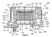
図3および4は、図2から2Cに示されたカメラの画像取込モジュールまたはタレット202を貫通する断面図であり、図5および6は、画像取込モジュール202の前部および後部の分解図であり、図3は、タレット202を貫通する垂直断面図であり、図4は、図3に示した線6−6において、上方向に見た水平断面図である。図3から6は、同様の番号を用いて一緒に説明される。
FIGS. 3 and 4 are cross-sectional views through the image capture module or
タレット202は、外部ハウジング300を含む。外部ハウジングは、アルミニウムから機械加工されるが、鋳造マグネシウムまたはプラスチックなどの代替の構造が使用されてもよい。ハウジング300は、半径部304を介してテーパ部306内に合流する略円筒状の前方向部分302を含む。テーパ部306は、その後縁において別の円筒状部分308に移行し、その後ハウジングは、短いショルダ310へとそれる。ハウジング300は、中央孔312を有し、この中央孔312は、その前部から後部にかけて半径が低減するように一連の段を含む。孔312の長さに沿った中間部には、ねじ切りされたセクション314が存在し、ねじ山は、略円筒状のねじ切りされた外面318と、テーパにされた内面320とを有する挿入体316と係合するために使用される。テーパにされた内面320は、複数の畝部または溝を含んで、カメラの画像中心に至る反射防止内部面を形成する。
本体300の前部には、レンズ装着体322が配置される。レンズ装着体322は、これに嵌合されたレンズに当接する前方を向く装着表面324を有する。レンズ装着体322はまた、さまざまな機械的詳細部、たとえば326を含み、この詳細部は、レンズ装着体322に取り付けられたレンズ上のバイヨネット継手と係合するために使用される。
A
孔312の深さに沿った約4分の3のところでは、孔は、328において内方向に入り込む。ショルダ328は、使用時に光の非可視波長を除去する光学フィルタ330を支持する。フィルタ330は、溝335内に受け入れられるOリングシール332によって所定場所に保持される。Oリング332は、その溝内に保持され、フィルタ330は、所定場所に保持され、ねじ切りされた挿入体316が孔312内にねじ込まれることによってOリング332にシールされる。フィルタ330の後続に空隙334が存在する。空隙334は、段付きプロファイルを有し、ショルダ328から外方向に開く。空隙の周囲壁336は、後方向に突出するフランジ338によって画定される。
At about three quarters along the depth of
タレット202の最も後方向の端部には、画像センサ組立体340が存在する。画像センサ組立体340は、この例では、画像感知チップ344を担持する印刷回路板の基板である基板342を含む。画像センサ組立体340は、一連のねじ348を介してハウジング300に装着される。ねじは、画像センサ組立体340をタレットハウジング300に装着する際に画像センサ組立体340の調整可能な装着をもたらすために使用される。装着は、追加的に、薄金のシムなどのような1つ以上のスペーサを含むことができ、このスペーサは、ハウジング300に対するセンサ組立体340の位置決めを調整するために使用され得る。特に、撮像センサ344が、アパーチャ312の中央軸に対して正しく位置すること、および前方向および後方向のその位置が、レンズ装着体322の前部装着面324に対して正確に設定されることが重要である。EF装着体の場合、装着面324と像平面の間の間隔は、公称で44mmである。この長さは、レンズを含むことで距離が長くなりまたは短くなることがあるため、レンズ装着体と画像センサ344の間に配置された光学システムの構成によって大きく変わり得る。さらに、異なるレンズ装着体または外部レンズシステムを使用しようとすれば、異なる予め決められた間隔が要求され得る。ハウジング300およびセンサ組立体340の製造公差は、センサ組立体340の位置を数ミリメートルで、たとえば0.2mm未満で調整可能にすることを必要とし得る。しかし、より良好な精度が望ましい。この場合、使用されるスペーサは、約0.025mmの厚さの金属シムであることができる。しかし、他のサイズが使用されてよい。
An
撮像センサ344の構造により、センサの像平面は、撮像センサの前表面でないことがある。そうではなく、これは、撮像センサの深さ内へといくらか戻る距離で設定され得る。この場合、機械的方法またはジグを使用して装着深さをセンサの像平面に合わせて直接的に較正することは可能でない。したがって、像平面の位置を推測するためにレンズ装着体322の前部装着面324と、撮像センサの像平面に対して知られている位置に位置する撮像センサ上の地点との間の距離を決定すること、または光学手段によって、たとえば画像センサ位置が、投影されたテスト画像がセンサ上に正しく焦点合わせされるように調整される後側焦点較正を実施するなどによって像平面の位置を決定することが必要となる。
Depending on the structure of the
たとえば、センサの構造により、センサの像平面を画定するセンサの成形表面は、センサの前面の下方の特定の深さ、たとえば1mmから2mmに位置することができる。これは、EFレンズ装着体の44mmの公称焦点距離では、レンズ装着体表面から撮像センサの面までの距離は、このオフセットによって44mmから低減される必要があることを意味する。 For example, depending on the structure of the sensor, the molding surface of the sensor that defines the image plane of the sensor may be located at a certain depth below the front surface of the sensor, for example 1 mm to 2 mm. This means that at a nominal focal length of 44 mm for the EF lens mount, the distance from the lens mount surface to the surface of the imaging sensor needs to be reduced from 44 mm by this offset.
撮像組立体の後側上にシールをもたらすために、U字形状のチャネルを間に画定する直立シーリングフランジの対を備えたシール350が存在する。シール350の最も内側の縁は、撮像センサ344を取り囲み、直立フランジは、ハウジング300のフランジ338に対するシールを形成する。このシールは、フィルタ330の最も後部の壁と撮像センサ344の間にシールされた空隙を画定する。この空間は、汚れ、埃、水分、および他の汚染物質に対してシールされる。撮像組立体340の後面は、追加的に、コネクタ352を含み、このコネクタ352は、撮像センサ344から本体204内に位置するデータ処理システムにデータを読み出すために、多導体コネクタを受け入れるように構成される。図3に最適に見ることができるように、ハウジング300は、追加的に、角度付けされたチャネル354を含み、この角度付けされたチャネル354は、レンズ装着体322の電気的およびデータ接点をカメラのデータ処理システムに接続するための一連のワイヤを受け入れるように配置される。図4に最適に見ることができるように、ハウジングは、追加的に、ボタン構成部360を含み、このボタン構成部360は、レンズ装着体322に取り付けられたレンズのための解放機構の一部を形成する。ボタンは、ハウジング300内のアパーチャ364から突出し、ピン366に連結された、ばね負荷されたボタン部材362を含む。ピン366は、拡張されたとき、レンズ装着体322に取り付けられたレンズ内の適合可能な受け入れ穴と係合し、レンズがレンズ装着体322に対して回転することを防止して、レンズの予期せぬ取り外しを防止する。ボタン362は、押されたときにこれを誘導するために相補的に成形された空洞364内で摺動するように配置される。
To provide a seal on the rear side of the imaging assembly, there is a
画像取込モジュール202の構造を良好に示すために、前部および後部の分解図が、図5および6としてそれぞれ提供される。図3および4に示す構成要素に加えて、この図はまた、構成要素に装着されて熱を撮像センサから外方に伝達することができる冷却システムも示している。構成要素は、モジュール202の前部から、レンズ装着体322から始めて簡潔に説明される。
To better illustrate the structure of the
レンズ装着体322は、レンズが装着された機械的構造をもたらす機械的装着リング322Aを備える。ばね323は、レンズをボタン組立体360と一緒に保持するために使用される。接点組立体329は、レンズとの電気的およびデータ接続を施すために使用される。接点組立体329は、ねじ325によってハウジング300に装着される。機械的装着リング322Aが、ねじ321を用いてハウジング300に装着される。
The
フィルタ330が、ハウジング300に挿入され、Oリング332によってこれにシールされる。Oリングは、挿入物316によって所定位置に保持される。
A
ハウジング300の後側に移ると、最初に、ハウジング300の内側と基板342上に装着された画像センサ344とを係合するシール350が位置する。センサの位置は、製造および較正中、ハウジング300と基板342の対向面341との間にシム351などの1つ以上のスペーサを置くことによって調整可能である。基板342は、ねじ348によってハウジングに保持される。要素355は、本体ハウジング内に装着されたマイクロホン(図示せず)の背部を覆うシールである。次に、受け板351が、冷却システム500の構成要素用の機械的装着体をもたらすために設けられる。冷却システムは、画像センサ344と熱接触状態で装着されたペルチェ冷却子1000およびヒートパイプ1004を含む。受け板351は、ここを貫通する穴357を有して、冷却子1000を画像センサ344に直接的に接触させることを可能にする。ヒートパイプ1004は、ねじ1008およびばね1009によって所定場所に固定された装着プレート1006によって、冷却子1000の高温側に保持される。
Moving to the rear side of the
図7および8は、図3および4に示すタレット202の断面図に対応する断面図を示すが、代わりにカメラ200の本体204を示している。側面図では、本体204は、略台形の形状であり、一方で水平断面図では、略矩形である。本体モジュール204は、使用時にタレット202を受け入れる大きい円の凹部702、その前面を含む。本体モジュール204のハウジング700を形成する主要本体は、円周方向ハウジングを備える。ハウジングは、上壁703、底壁704、側壁706および708(この断面の位置により、またその中にドアが設けられることによりあまり詳細には示されない)を含む。ハウジング700は、追加的に、一体的に形成された前壁710を含み、ハウジング700の前部および後部の表面には、カバー712および714がそれぞれ設けられる。カバー712および714は、その中に形成されたボタンおよび他のインターフェース要素を有する。
7 and 8 show a cross-sectional view corresponding to the cross-sectional view of the
図7に最適に見ることができるように、ハウジング700の底面は、換気がそこを通ってもたらされるパネル714を含む。ハウジング700の後面は、ディスプレイ718およびタッチ感知式インターフェース720を含む、中央に装着されたディスプレイスクリーン716を含む。これは、ハウジング700に固着され、ハウジング700の後部を閉じる装着プレート基板722上に装着される。図8に見ることができるように、ハウジング700の各側は、短い隠し凹部724を含む。これらの凹部は、サンシェードなどのような外部補助装置のための装着点として設けられる。
As best seen in FIG. 7, the bottom surface of
次に、前に述べたようにアルミニウムなどの材料のソリッドブロックから機械加工され得るハウジング700、およびタレット組立体202の斜視図を示す図9を見る。
Next, see FIG. 9 which shows a perspective view of
この時点において、タレット組立体202は、ほぼ完成状態であるものとして示されているが、一方では本体モジュール204のハウジング700は、比較すると相対的に不完全な状態であることに注目すべきである。これらの2つのモジュール間の組立体の段階におけるこうした相違は、本発明の好ましい実施形態の重要な利点を示す。すなわち、タレットは、本体モジュール204から完全に別個に製造され得る。これは、本体が提供された後、すべての光学構成要素がその中に別個に装着される必要があり、カメラが本体周りで作り上げられる必要がある、従来のカメラ製造と比較してさまざまな利点を有する。代わりに、本発明の好ましい実施形態は、タレット202だけを組み付けてその最終形態にすることができる。タレット202は、これがカメラの他の構成要素と一緒にされる前に較正され正しく作動するように試験され得る。
At this point, it should be noted that while the
一部の形態では、タレット202には、画像センサに関連する較正データを記憶するためのメモリ(たとえば図1のメモリ120)が設けられる。画像センサ118の応答は、製造時には不完全であり、その結果、センサのピクセルは異なる光変換効率を有する。
In some forms, the
したがって、カメラは、パフォーマンスにおけるこの変動を考慮するように較正される必要がある。較正の結果、たとえばセンサ上のピクセルごとに較正データが生み出される。画像の読み出しまたは処理において、この較正データは、整合した画像を生み出すためにセンサからの生データを補正するために使用される。 Therefore, the camera needs to be calibrated to account for this variation in performance. As a result of the calibration, for example, calibration data is generated for each pixel on the sensor. In image readout or processing, this calibration data is used to correct the raw data from the sensor to produce a matched image.
較正データはセンサ毎に独自のものであり、また本発明の好ましい実施形態では、センサを、カメラ全体ではなく画像取込モジュールに関連付けるので、このデータを、タレット202内に収容されたメモリ内のチップと一緒に記憶することが有利になり得る。これは、完全に組み立てられたカメラに対するタレットの別個の較正を容易にし、タレットの取り替えも可能にする。カメラの電源が入れられるたびに、主要プロセッサは、それ自体のメモリからそれ自体の構成を読み出し、次いで、タレット202のメモリから較正情報を読み出す。
The calibration data is unique for each sensor, and in the preferred embodiment of the present invention, the sensor is associated with the image capture module rather than the entire camera, so this data is stored in a memory contained within the
さらに、タレット202内の画像センサの像平面は、タレット202の製造の完了後にシールされるため、その製造中に必要とされるやり方で取り扱われることをもはや必要としない。その製造中、理想的には、タレットは、クリーンルーム設備内にあり、極めて埃の無い、汚染物質の無い環境下で製造される。これは、費用のかかるプロセスであり、実施するのに十分に訓練を積んだ技術者を必要とする。それに反して、本体モジュール204およびタレット202の本体モジュール204への装着は、従来の電子装置製造設備内で実施可能である。これらは清潔であり、比較的静電気および汚染物質が無いものであるが、クリーンルームの状態に等しいものではない。したがって、このタイプの環境内での組み立ては、クリーンルーム設備内で実施される等価の組み立てよりかなり安い。
Further, the image plane of the image sensor in the
画像取込モジュール202の別個の製造および本体モジュール204への組み付けの追加の利点は、画像取込モジュール202の別個の試験が実施可能であることである。この事前の試験は、不良製品が製造される可能性を低減し、またはタレット組立体202はカメラへのその組み込み前にすでに試験されているため、完成した製品の不良の形態を本体またはタレット202へのその連結に少なくとも狭める。さらに、カメラが修理される、もしくは解体される必要がある場合、または撮像システムの完全な故障の場合、これは、タレット202を本体モジュール204から取り外すことによって実施され得る。損傷したまたは故障したタレット202は、機能ユニットおよび実施される残りの構成要素の再組み立てによって取り代えられ得る。カメラが従来の製造技術によって作製される場合、カメラ全体は、カメラの繊細な光学構成要素を取り扱うために適合された環境内で分解されおよび再組み立てされる必要がある。理想的には、これは、クリーンルーム状態を意味する。しかし、現場に出た中古カメラの場合、このカメラを保全のためにクリーンルーム内に入ることを可能にする清潔性の状態までもっていくことができる可能性は低い。本発明の特定の実施形態は、タレットのみが、これが保全目的または改修のために作業される場合、清潔性のそのような厳しい基準を満たせばよいため、この問題を軽減する。
An additional advantage of separate manufacture of the
次に図9に戻ると、画像取込モジュール202を主要本体モジュール204のハウジング700に装着するために、組み立てられた画像取込モジュール202は、後方からアパーチャ702を通って挿入されることを見ることができる。この例で使用される組み立てプロセスは、事前に組み立てられた画像取込モジュールを、組み立ての初期段階で主要本体204のハウジング内に組み入れることを含む。主要本体モジュール204の残りは、次いで、画像取込モジュール202の周りに組み立てられ、それにより、画像取込モジュール202は完成したカメラ内に組み込まれる。あるいは、事前に組み立てられた画像取込モジュール202は、事前に組み立てられた主要本体モジュール(または他のモジュール)に装着され得る。これらの例ではいずれも、画像取込モジュール202とカメラの他の構成要素との間に必要な電気、データおよび/または熱的接続を施す必要がある。この場合、熱的接続は、ヒートパイプ1004の上面1005を画像取込モジュール202用の熱インターフェースとして用いて、熱インターフェースを本体モジュール204の構成要素と接触させることによって施され、それにより、熱は、画像取込モジュール202から外にこうして伝導される。この場合、熱は、本体モジュール204の本体ハウジング700に伝導される。
Returning now to FIG. 9, it will be seen that the assembled
図10および11は、組み立てられたカメラ200を貫通する断面図を示す。図10の断面は、図3および7に示す断面に対応する垂直断面である。図11に示す水平断面は、図4および8の水平断面に対応する。明確にするために、先に図示しない構成要素のみが、読手に対して図を混乱させないためにこれらの図において番号付けされる。
10 and 11 show cross-sectional views through the assembled
図10および11に見ることができるように、画像取込組立体またはタレット202は、主要本体モジュール204に機械的に装着される。
As can be seen in FIGS. 10 and 11, the image capture assembly or
理解されるように、本体モジュール204は、完成したカメラ200内に追加の構成要素を担持する。これらの要素の選択されたものが、便宜上図示される。しかし、追加の構成要素は、本発明の他の実施形態において存在する。これもまた理解されるように、タレット202は、本体204内に装着された電力供給装置に電気的に接続され、画像取込システムもまた、本体内のデータ処理システムに接続される。図1に関連して予示したように、熱的接続がまた、画像取込モジュール202と主要本体204の間に施される。この実施形態では、熱的接続は、ペルチェ冷却装置1000の組合わせによって形成され、このペルチェ冷却装置1000は、基板342内の穴345を通って撮像センサ344の後面に装着される。ペルチェ冷却子1000は、画像センサ344に装着された面からその後面1002に熱を引き出す。ヒートパイプ1004は、ペルチェ冷却子1000の面1002と物理的に接触して装着される。ヒートパイプ1004は、逆L字形状であり、ペルチェ冷却子1000から上方向に延び、ハウジング700の上壁703に接触する。ヒートパイプ1004はまた、熱を、環境への消散のために、ペルチェ冷却子1000の高温側1002から表面1005を介してハウジング700に伝達するように作用する。既に論じたように、ハウジングによって実施されるこの熱消散機能は、金属ハウジングを有することによって向上される。ヒートパイプ1004は、ばね付きのねじ1008の対によって所定場所に締め付けられた装着プレート1006によってペルチェ冷却子と接触して保持される。ハウジングモジュール204は、追加的に、カメラの主要な電子装置および処理システムを含む主要回路板1010を収容する。回路板1010の後方に装着されるのは、ソリッドステートドライブなどの取り外し可能な記憶装置を受け入れるように構成された略矩形のベイ1012である。ソリッドステートドライブは、ハウジング700の側部に装着された(先に図3で示した)ドア230を開くことによってベイ1010に挿入され、そこから取り外される。一連のコネクタおよび他の入力/出力ポートは、1012に位置し、ドア1014を介してアクセスされる。図11は、追加的に、この実施形態における電池1016の位置を示している。
As will be appreciated, the
図12から17は、第2の画像取込モジュールおよびこの画像取込モジュールを用いて作製されたカメラの実施形態を示してる。図12から17では、図1から11の実施形態において対応する要素を有する第2の実施形態の要素が、「A」を加える以外は共通である参照番号で標識され、共通の構成要素は、理解を助けるために同様に番号付けされる。図12および13は、画像取込モジュールまたはタレット202Aを貫通する断面図であり、図14および15は、画像取込モジュール202Aの前部および後部の分解図である。
FIGS. 12 to 17 show an embodiment of a second image capture module and a camera made using this image capture module. 12 to 17, elements of the second embodiment having corresponding elements in the embodiments of FIGS. 1 to 11 are labeled with a reference number that is common except for adding “A”, and the common components are: Numbered as well to aid understanding. 12 and 13 are cross-sectional views through the image capture module or
図12は、タレット202Aを貫通する垂直の断面図であり、図13は、図12に示す線13−13における、上方向に見た水平断面図である。図12から15は、同様の番号を用いて一緒に説明される。
12 is a vertical cross-sectional view passing through the
最初に見て理解されるように、タレット202Aは、図1から11のタレット202と比較して相対的に短い。タレット202Aは、外部ハウジング300Aを含む。外部ハウジングは、アルミニウムから機械加工されるが、鋳造マグネシウムまたはプラスチックなどの代替の構造が使用されてもよい。ハウジング300Aは、半径部304Aを介してテーパ部306A内に合流する、短い、略円筒状の前方部分302Aを含む。テーパ部306Aは、その後縁において別の円筒状部分308Aに移行し、その後ハウジングは、短いフランジ310Aへとそれる。ハウジング300Aは、中央孔312Aを有し、この中央孔312Aは、その前部から後部にかけて半径が低減するように一連の段を含む。孔312Aの内面320Aは、複数の畝部または溝を含んで、カメラの画像中心に至る反射防止内部面を形成する。
As initially seen and understood, the
本体300Aの前部には、レンズ装着体322Aが配置される。レンズ装着体322Aは、これに嵌合されたレンズに当接する前方を向く装着表面324Aを有する。レンズ装着体322Aはまた、さまざまな機械的詳細部、たとえば326Aを含み、この詳細部は、レンズ装着体322Aに取り付けられたレンズ上のバイヨネット継手と係合するために使用される。
A
孔312Aの後方端部に向かって、使用時、光の非可視波長を除去する光学フィルタ330Aを支持するショルダ328Aが設けられる。たいていの実施形態では、これは赤外線フィルタである。フィルタ330Aは、溝335A内に受け入れられるOリングシール332Aによって所定場所に保持される。フィルタ330Aの後ろに空隙334Aが存在する。空隙334Aの周囲壁336Aは、後方向に突出するフランジ338Aによって画定される。
A shoulder 328A that supports an optical filter 330A that removes invisible wavelengths of light in use is provided toward the rear end of the hole 312A. In most embodiments this is an infrared filter. Filter 330A is held in place by O-
タレット202Aの最も後方向の端部には、画像センサ組立体340Aが存在する。画像センサ組立体340Aは、この例では、画像感知チップ344Aを担持する印刷回路板の基板である基板342Aを含む。画像センサ組立体340Aは、一連のねじ348Aを介してハウジング300Aに装着される。ねじは、画像センサ組立体340Aをタレットハウジング300Aに装着する際に画像センサ組立体340Aの調整可能な装着をもたらすために使用される。装着は、追加的に、薄金のシム351Aなどのような1つ以上のスペーサを含むことができ、このスペーサは、ハウジング300Aに対するセンサ組立体340Aの位置決めを調整するために使用され得る。特に、撮像センサ344Aが、アパーチャ312Aの中央軸に対して正しく位置すること、および前方向および後方向のその位置が、レンズ装着体322Aの前部装着面324Aに対して正確に設定されることが重要である。この場合では、タレット202Aは、マイクロフォーサーズ装着体(MFT装着体)を有し、したがって、装着面324Aと像平面の間の間隔は、公称で19.2mmである。この長さは、レンズを含むことで距離が長くなりまたは短くなることがあるため、レンズ装着体と画像センサ344Aの間に配置された光学システムの構成によって大きく変わり得る。ハウジング300Aおよびセンサ組立体340Aの製造公差は、センサ組立体340Aの位置を数ミリメートルで、たとえば0.2mm未満で調整可能にすることを必要とし得る。しかし、より良好な精度が望ましい。この場合、使用されるスペーサは、約0.025mmの厚さの金属シムであることができる。しかし、他のサイズが使用されてよい。
An
撮像組立体の後側上にシールをもたらすために、U字形状のチャネルを間に画定する直立シーリングフランジの対を備えたシール350Aが存在する。シール350Aの最も内側の縁は、撮像センサ344Aを取り囲み、直立フランジは、ハウジング300Aのフランジ338Aに対するシールを形成する。このシールは、フィルタ330Aの最も後部の壁と撮像センサ344Aの間にシールされた空隙を画定する。この空間は、汚れ、埃、水分、および他の汚染物質に対してシールされる。撮像組立体340Aの後面は、追加的に、コネクタ352Aを含み、このコネクタ352Aは、撮像センサ344Aから、タレット202Aが中に組み込まれるカメラの本体内に位置するデータ処理システムにデータを読み出すために、多導体コネクタを受け入れるように構成される。図15に最適に見ることができるように、ハウジング300Aは、追加的に、チャネル354Aを含み、このチャネル354Aは、レンズ装着体322Aの電気的およびデータ接点をカメラのデータ処理システムに接続するための一連のワイヤ1202を受け入れるように配置される。図13に最適に見ることができるように、ハウジングは、追加的に、ボタン構成部360Aを含み、このボタン構成部360Aは、レンズ装着体322Aに取り付けられたレンズのための解放機構の一部を形成する。ボタンは、ハウジング300A内のアパーチャ364Aから突出し、ピン366Aに連結された、ばね負荷されたボタン部材362Aを含む。ピン366Aは、拡張されたとき、レンズ装着体322Aに取り付けられたレンズ内の適合可能な受け入れ穴と係合し、レンズがレンズ装着体322Aに対して回転することを防止して、レンズの予期せぬ取り外しを防止する。ボタン362Aは、押されたときにこれを誘導するために相補的に成形された空洞364A内で摺動するように配置される。
To provide a seal on the back side of the imaging assembly, there is a
画像取込モジュール202Aの構造をより良好に示すために、前部および後部の分解図が、図14および15としてそれぞれ提供される。これらの図は、図5および6に関連して示した冷却システムを省いているが、同一の冷却システムは、このタレット202Aに装着されて熱を撮像センサから外方に伝達することができる。あるいは、冷却機構は、画像センサ344Aに後で熱的に接続される本体モジュール204Aの一部を形成することができる。一部の実施形態では、能動的冷却子は必要でなく、十分な熱消散がこれ無しで達成され得る。
To better illustrate the structure of
レンズ装着体322Aは、レンズが装着された機械的構造をもたらす機械的装着リング322AAを備える。ばね323Aは、レンズをボタン組立体360Aと一緒に保持するために使用される。接点組立体329Aは、レンズとの電気的およびデータ接続を施すために使用される。機械的装着リング322AAは、ねじ(図示せず)を用いてハウジング300Aに装着される。
The
フィルタ330Aが、ハウジング300Aに挿入され、Oリング332Aによってこれにシールされる。
Filter 330A is inserted into
ハウジング300Aの後側に移ると、最初に、ハウジング300Aの内側、詳細にはフランジ336と基板342A上に装着された画像センサ344Aと係合するシール350Aが位置する。センサの位置は、製造および較正中、ハウジング300Aと基板342Aの対向面341Aとの間にシム351Aなどの1つ以上のスペーサを置くことによって調整可能である。基板342Aは、ねじ348Aによってハウジングに保持される。次に、受け板351Aが、冷却システムの構成要素用の機械的装着体をもたらすために設けられる。
Moving to the rear side of the
図16および17は、組み立てられたカメラ200Aを貫通する断面図を示す。図16の断面は、図12に示す断面に対応する垂直断面である。図13に示す水平断面は、図13の水平断面に対応する。明確にするために、先に図示しない構成要素のみが、読手に対して図を混乱させないためにこれらの図において番号付けされる。カメラ本体204は、図10および11に示したカメラ本体と同一であり、詳細に説明される必要はない。画像取込組立体またはタレット202Aは、前述の実施形態と同じやり方で主要本体モジュール204に機械的に装着される。
16 and 17 show cross-sectional views through the assembled camera 200A. The cross section of FIG. 16 is a vertical cross section corresponding to the cross section shown in FIG. The horizontal cross section shown in FIG. 13 corresponds to the horizontal cross section of FIG. For clarity, only those components not previously shown are numbered in these figures to avoid confusing the figures to the reader. The
本明細書にあげた例は、1つが画像取込モジュールである2つのモジュールを含む。しかし、カメラが、3つ以上のモジュールから形成可能であることが理解されよう。単なる一例として、カメラの1つ以上の他のモジュールとインターフェースする別個の電力供給モジュールが設けられてよい。一部の実施形態では、カメラは、1つ以上の第2の画像取込モジュールを含むことができる。第2の画像取込モジュールは、第1のものと同一でよく、または異なってもよい。第2の画像取込モジュール(複数可)は、第1の画像取込モジュールと共通の本体モジュールに装着され得る。そのような構成部は、複数の視点から画像(ビデオまたはスチル)を取り込むために使用されてよく、画像の取り込みにおいて特定の用途を見出して、3次元ビデオを作製する上で実施され得るような立体的画像の作製を可能にすることができる。 The examples given here include two modules, one of which is an image capture module. However, it will be appreciated that the camera can be formed from more than two modules. By way of example only, a separate power supply module may be provided that interfaces with one or more other modules of the camera. In some embodiments, the camera can include one or more second image capture modules. The second image capture module may be the same as the first or different. The second image capture module (s) may be mounted on a body module that is common with the first image capture module. Such a component may be used to capture images (video or still) from multiple viewpoints, such as can be implemented in finding specific applications in image capture and creating 3D video. It is possible to create a stereoscopic image.
図18は、第2の画像取込モジュールを有するカメラの主要機能ブロックを示す概略ブロック図である。カメラ1800は、3つの主要モジュール、すなわち2つの画像取込モジュール102および本体モジュール104から形成される。画像取込モジュール102の各々は、シールされた光学システムおよび画像取込システムを形成し、これらのシステムは、光を受け入れ、そのそれぞれの画像取込センサ内で画像を独立的に形成するように構成される。本体モジュール104は、カメラ1800の残りの機能サブシステムを収容する。
FIG. 18 is a schematic block diagram showing the main functional blocks of a camera having a second image capture module.
最初に、図1に関連して説明した画像取込モジュール102と各々が同じである、画像取込モジュール102を見ると、構成要素は、同じ参照番号で番号付けされており、再度説明されない。全般的に言えば、各々の画像取込モジュール102は、光学システム108、撮像センサ118、および支援する電子装置システムが中に装着された画像取込モジュールハウジング106から形成される。
Initially, looking at the
画像取込モジュール102は、主要本体モジュール104に機械的に連結される。また、画像取込モジュールと本体モジュール104の間(および場合によっては他の実施形態では画像取込モジュール間)に、データ、電力、および熱的接続も存在する。画像取込モジュールの互いにおよび本体ハウジングに対する機械的装着は、画像取込モジュール102間に予め決められた分離および位置合わせが存在するようにして行われる。最も好ましくは、装着は、画像取込モジュールの光学システムが、相対的に配置および位置合わせされ、それにより、各々によって取り込まれた画像が、3次元ビデオを作り出すように組み合わされ得るようなものである。装着機構は、相対的位置決めの調整を可能にするように調整可能になり得る。
The
これもまた理解されるように、立体的画像はまた、複数の画像取込センサまたは特化された光学システムを備えた画像取込モジュールを用いて取り込まれ得る。
前述で理解することができるように、好ましい実施形態によって作製されたカメラは、モジュールのハウジング内に装着された画像センサおよび光学システムを含む画像取込モジュール(複数可)を含む。このタイプの別個のモジュール(複数可)の使用は、カメラの製造性、試験、および保全を向上させることができるが、これは、カメラの残りの部分、たとえば1つ以上の追加のモジュールまたは構成要素が、画像取込モジュールと同じ公差または同じ状態で製造される必要はないためである。
As will also be appreciated, stereoscopic images can also be captured using an image capture module with multiple image capture sensors or specialized optical systems.
As can be seen above, a camera made according to a preferred embodiment includes an image capture module (s) that includes an image sensor and an optical system mounted within the housing of the module. The use of this type of separate module (s) can improve the manufacturability, testing and maintenance of the camera, but this may affect the rest of the camera, eg, one or more additional modules or configurations This is because the elements need not be manufactured with the same tolerances or the same conditions as the image capture module.
本明細書において開示し、規定した本発明は、本文または図に述べたまたはそれらから明確である個々の特徴の2つ以上のすべての代替的組み合わせに及ぶことが理解されよう。これらの異なる組み合わせのすべては、本発明のさまざまな代替的態様を構成する。 It will be understood that the invention disclosed and defined herein extends to all alternative combinations of two or more of the individual features described in or apparent from the text or figures. All of these different combinations constitute various alternative aspects of the invention.
Claims (32)
本体ハウジングを含む本体モジュールと、
シールされたモジュールである画像取込モジュールであって、
ハウジングと、
光を電気信号に変換する少なくとも1つの画像センサと、
前記画像センサに関連付けられ、光を前記ハウジングを通して前記少なくとも1つの画像センサに伝送するように配置された光学システムと、
レンズまたは他の光学モジュールを前記画像取込モジュールに連結させるために前記レンズまたは他の光学モジュールと解放可能に係合する連結器を含むレンズ装着体とを含む、画像取込モジュールとを含み、
前記画像取込モジュールが、前記本体ハウジングに直接的または間接的に装着され、画像を取り込むために前記本体モジュールと相互作動可能である、カメラ。 A camera,
A body module including a body housing;
An image capture module that is a sealed module,
A housing;
At least one image sensor for converting light into an electrical signal;
An optical system associated with the image sensor and arranged to transmit light through the housing to the at least one image sensor;
An image capture module, including a lens mount that includes a coupler that releasably engages the lens or other optical module to couple a lens or other optical module to the image capture module;
The camera, wherein the image capture module is mounted directly or indirectly on the body housing and is interoperable with the body module to capture an image.
電力を前記画像取込モジュールに供給するように配置された電力供給サブシステム、
前記画像取込モジュールの画像センサから受け入れられた画像データを処理するデータ処理システム、
前記画像取込モジュール内で生成された熱を消散させるように配置された熱制御サブシステム、
前記画像取込モジュールのユーザ制御を可能にするユーザインターフェースサブシステム、
前記画像取込モジュールの画像センサから導かれたデータを記憶するデータ記憶サブシステム、
別の装置とのデータまたは電気的接続を可能にする入力および/または出力サブシステム
のいずれか1つ以上が、前記本体モジュールの前記ハウジング内に装着される、請求項1または2のいずれか一項に記載のカメラ。 The following subsystems:
A power supply subsystem arranged to supply power to the image capture module;
A data processing system for processing image data received from an image sensor of the image capture module;
A thermal control subsystem arranged to dissipate heat generated in the image capture module;
A user interface subsystem enabling user control of the image capture module;
A data storage subsystem for storing data derived from an image sensor of the image capture module;
3. Any one or more of input and / or output subsystems that allow data or electrical connection with another device are mounted within the housing of the body module. The camera according to item.
1つ以上のレンズ、
1つ以上のフィルタ、
1つ以上の偏光子、
光透過性カバー
を含む群から選択されたものを含む光透過性要素を含む、請求項8に記載のカメラ。 The one or more light transmissive elements are:
One or more lenses,
One or more filters,
One or more polarizers,
The camera of claim 8, comprising a light transmissive element comprising a member selected from the group comprising a light transmissive cover.
データ接続、
電力接続、
熱的接続
の少なくとも1つを施すことをさらに含む、請求項21または22のいずれかに記載の方法。 The following connections between the image capture module and another module of the camera:
Data connection,
Power connection,
23. A method according to any of claims 21 or 22, further comprising applying at least one of the thermal connections.
Applications Claiming Priority (3)
| Application Number | Priority Date | Filing Date | Title |
|---|---|---|---|
| AU2012901461A AU2012901461A0 (en) | 2012-04-13 | Camera | |
| AU2012901461 | 2012-04-13 | ||
| PCT/AU2013/000381 WO2013152402A1 (en) | 2012-04-13 | 2013-04-12 | Camera |
Related Child Applications (1)
| Application Number | Title | Priority Date | Filing Date |
|---|---|---|---|
| JP2019000223A Division JP2019071656A (en) | 2012-04-13 | 2019-01-04 | camera |
Publications (1)
| Publication Number | Publication Date |
|---|---|
| JP2015518681A true JP2015518681A (en) | 2015-07-02 |
Family
ID=49326957
Family Applications (2)
| Application Number | Title | Priority Date | Filing Date |
|---|---|---|---|
| JP2015504821A Pending JP2015518681A (en) | 2012-04-13 | 2013-04-12 | camera |
| JP2019000223A Withdrawn JP2019071656A (en) | 2012-04-13 | 2019-01-04 | camera |
Family Applications After (1)
| Application Number | Title | Priority Date | Filing Date |
|---|---|---|---|
| JP2019000223A Withdrawn JP2019071656A (en) | 2012-04-13 | 2019-01-04 | camera |
Country Status (5)
| Country | Link |
|---|---|
| US (3) | US9661235B2 (en) |
| EP (1) | EP2837171A4 (en) |
| JP (2) | JP2015518681A (en) |
| CN (1) | CN104471923A (en) |
| WO (1) | WO2013152402A1 (en) |
Cited By (1)
| Publication number | Priority date | Publication date | Assignee | Title |
|---|---|---|---|---|
| JP2020181846A (en) * | 2019-04-23 | 2020-11-05 | 京セラ株式会社 | Electronic apparatus, imaging device, and movable body |
Families Citing this family (45)
| Publication number | Priority date | Publication date | Assignee | Title |
|---|---|---|---|---|
| WO2012058641A2 (en) * | 2010-10-29 | 2012-05-03 | The Regents Of The University Of California | Cellscope apparatus and methods for imaging |
| JP6199014B2 (en) * | 2012-07-26 | 2017-09-20 | 株式会社ザクティ | Lens unit and image pickup apparatus having the same |
| WO2015035229A2 (en) | 2013-09-05 | 2015-03-12 | Cellscope, Inc. | Apparatuses and methods for mobile imaging and analysis |
| KR20150072899A (en) * | 2013-12-20 | 2015-06-30 | 삼성전자주식회사 | Lens mounting module and interchangeable lens system photographing apparatus having the same |
| US9258465B2 (en) * | 2014-01-09 | 2016-02-09 | Omnivision Technologies, Inc. | Image device having efficient heat transfer, and associated systems |
| CN106999994B (en) | 2014-10-17 | 2020-12-22 | 妮玛·纳巴维 | Self-cleaning optical sensor assembly |
| EP3068125A1 (en) * | 2015-03-09 | 2016-09-14 | Delphi Technologies, Inc. | A method of manufacturing a multiple view camera system and multiple view camera system |
| KR102100340B1 (en) * | 2015-03-31 | 2020-04-13 | 캐논 가부시끼가이샤 | Apparatus body of image pickup apparatus |
| JP6176283B2 (en) * | 2015-04-17 | 2017-08-09 | トヨタ自動車株式会社 | Electrical connector and board mounting method of electrical connector |
| US9769361B2 (en) * | 2015-08-31 | 2017-09-19 | Adlink Technology Inc. | Assembly structure for industrial cameras |
| US9995990B2 (en) | 2015-12-15 | 2018-06-12 | Gopro, Inc. | Removable camera lens cover |
| FR3051616B1 (en) * | 2016-05-23 | 2019-06-07 | Institut National De L'information Geographique Et Forestiere (Ign) | DIGITAL VIEWING APPARATUS |
| CN206542527U (en) * | 2017-03-09 | 2017-10-03 | 中磊电子(苏州)有限公司 | Network monitor |
| JP6919242B2 (en) * | 2017-03-16 | 2021-08-18 | 株式会社リコー | Voice acquisition device |
| US10694085B2 (en) * | 2017-09-01 | 2020-06-23 | Mtd Products Inc | Optical sensor housing |
| CN112689447A (en) * | 2017-10-12 | 2021-04-20 | 深圳市大疆灵眸科技有限公司 | Heat radiation structure, camera and moving platform |
| US10855890B2 (en) | 2017-10-23 | 2020-12-01 | Magna Electronics Inc. | Camera for vehicle vision system with enhanced heat removal |
| WO2020043116A1 (en) * | 2018-08-28 | 2020-03-05 | Zhejiang Dahua Technology Co., Ltd. | Systems and methods for adjusting position of photosensitive chip of image acquisition device |
| US11683911B2 (en) | 2018-10-26 | 2023-06-20 | Magna Electronics Inc. | Vehicular sensing device with cooling feature |
| US10911647B2 (en) | 2018-11-12 | 2021-02-02 | Magna Electronics Inc. | Vehicular camera with thermal compensating means |
| EP3751973B1 (en) * | 2019-04-28 | 2021-12-15 | SZ DJI Technology Co., Ltd. | Heat dissipation assembly and motion camera |
| US12078694B2 (en) | 2019-07-30 | 2024-09-03 | Google Llc | Sensor-based tamper detection for mounted electronic devices |
| JP7379018B2 (en) * | 2019-08-20 | 2023-11-14 | キヤノン株式会社 | Imaging device |
| US11533415B2 (en) * | 2019-09-16 | 2022-12-20 | Gopro, Inc. | Anti-fog measures for image capture device |
| US11425286B2 (en) * | 2020-03-31 | 2022-08-23 | Gopro, Inc. | Housing assembly for image capture devices |
| US11630376B2 (en) | 2020-06-18 | 2023-04-18 | Gopro, Inc. | Removable lens accessories for image capture devices |
| US11474417B2 (en) | 2020-08-07 | 2022-10-18 | Lineage Logistics, LLC | Lens heater assembly for camera |
| USD974450S1 (en) | 2020-08-28 | 2023-01-03 | Gopro, Inc. | Camera lens attachment |
| USD967890S1 (en) | 2020-08-28 | 2022-10-25 | Gopro, Inc. | Camera lens attachment |
| US11600023B2 (en) | 2020-08-31 | 2023-03-07 | Gopro, Inc. | Optical center calibration |
| US11528417B2 (en) | 2020-08-31 | 2022-12-13 | Gopro, Inc. | Calibrating an image capture device with a detachable lens |
| US11852957B2 (en) | 2020-09-22 | 2023-12-26 | Google Llc | Thermal-control system for a security camera and associated security camera |
| US11277941B1 (en) | 2020-10-02 | 2022-03-15 | Google Llc | Thermal-control system of a video-recording doorbell and associated video-recording doorbells |
| DE102020007881B3 (en) | 2020-12-11 | 2022-06-15 | Baumer Optronic Gmbh | Camera and method for producing a camera with a housing with a temperature control channel |
| US11477352B1 (en) * | 2021-04-09 | 2022-10-18 | Microsoft Technology Licensing, Llc | Accessory device heat dissipation by parent device |
| US11647270B2 (en) * | 2021-06-15 | 2023-05-09 | Gopro, Inc. | Bayonet connecting an optical system with a split lens to an image capture device |
| US11606488B2 (en) | 2021-06-15 | 2023-03-14 | Gopro, Inc. | Integrated sensor and lens assembly mount |
| US11503194B1 (en) * | 2021-07-21 | 2022-11-15 | Logitech Europe S.A. | Coupling system for a peripheral device |
| JP7759231B2 (en) * | 2021-10-21 | 2025-10-23 | キヤノン株式会社 | Imaging device, control method and program thereof |
| JP2023163923A (en) * | 2022-04-28 | 2023-11-10 | キヤノン株式会社 | Imaging device |
| JP1769831S (en) * | 2022-09-07 | 2024-05-07 | camera | |
| US11899349B1 (en) | 2023-05-10 | 2024-02-13 | Quick Quack Car Wash Holdings, LLC | Systems for image projection |
| US12429752B2 (en) | 2023-07-21 | 2025-09-30 | Gopro, Inc. | Replaceable lens module having a spring plate |
| USD1104115S1 (en) | 2024-06-26 | 2025-12-02 | Gopro, Inc. | Camera lens |
| USD1104116S1 (en) | 2024-06-26 | 2025-12-02 | Gopro, Inc. | Camera lens |
Citations (8)
| Publication number | Priority date | Publication date | Assignee | Title |
|---|---|---|---|---|
| JPH08172561A (en) * | 1994-12-19 | 1996-07-02 | Olympus Optical Co Ltd | Camera, plug-in unit and camera system |
| JP2006086752A (en) * | 2004-09-15 | 2006-03-30 | Fuji Photo Film Co Ltd | Lens interchangeable camera integral with imaging element and interchangeable lens unit integral with imaging element |
| JP2009100374A (en) * | 2007-10-18 | 2009-05-07 | Olympus Imaging Corp | Image sensor cooling unit, photographing lens unit, and electronic apparatus |
| JP2010060976A (en) * | 2008-09-05 | 2010-03-18 | Nikon Corp | Camera and guide member |
| JP2011078073A (en) * | 2008-11-26 | 2011-04-14 | Ricoh Co Ltd | Camera body, image pickup unit, imaging system, attachment/detachment method of image pickup unit to/from camera body, mounting method of image pickup unit to camera body, and demounting method of image pickup unit from camera body |
| JP2011139138A (en) * | 2009-12-25 | 2011-07-14 | Toshiba Teli Corp | Small industrial electronic imaging camera |
| WO2011101928A1 (en) * | 2010-02-22 | 2011-08-25 | パナソニック株式会社 | Three-dimensional image capturing adopter, hybrid image-capturing system, and electronic camera |
| JP2012075078A (en) * | 2010-08-31 | 2012-04-12 | Panasonic Corp | Camera body, imaging apparatus, camera body control method, program, and recording medium with program recorded thereon |
Family Cites Families (28)
| Publication number | Priority date | Publication date | Assignee | Title |
|---|---|---|---|---|
| JP3284585B2 (en) * | 1992-04-10 | 2002-05-20 | ソニー株式会社 | Electronic equipment cooling device |
| US5839284A (en) * | 1995-10-04 | 1998-11-24 | Raytheon Ti Systems, Inc. | Image intensifier tv integral thermal control system |
| US6483101B1 (en) * | 1999-12-08 | 2002-11-19 | Amkor Technology, Inc. | Molded image sensor package having lens holder |
| DE60129831T2 (en) * | 2000-09-25 | 2008-04-30 | Sensovation Ag | Apparatus and method for optical measurement |
| FR2832917B1 (en) * | 2001-11-30 | 2004-09-24 | Spine Next Sa | ELASTICALLY DEFORMABLE INTERVERTEBRAL IMPLANT |
| DE10218313B4 (en) * | 2002-04-24 | 2018-02-15 | Arnold & Richter Cine Technik Gmbh & Co. Betriebs Kg | Digital motion picture camera |
| US20040169771A1 (en) * | 2003-01-02 | 2004-09-02 | Washington Richard G | Thermally cooled imaging apparatus |
| JP4225860B2 (en) * | 2003-07-29 | 2009-02-18 | Hoya株式会社 | Digital camera |
| JP2005181630A (en) * | 2003-12-18 | 2005-07-07 | Konica Minolta Photo Imaging Inc | Camera |
| JP4270455B2 (en) * | 2004-03-26 | 2009-06-03 | 富士フイルム株式会社 | Solid-state imaging device |
| JP4448009B2 (en) | 2004-11-11 | 2010-04-07 | キヤノン株式会社 | Surveillance camera |
| CN100470349C (en) * | 2005-06-28 | 2009-03-18 | 华硕电脑股份有限公司 | Image acquisition module |
| US20060291853A1 (en) * | 2005-06-24 | 2006-12-28 | Asustek Computer Inc. | Electronic device and image capture module thereof |
| US7632023B2 (en) | 2005-12-19 | 2009-12-15 | Fujifilm Corporation | Camera |
| KR100828943B1 (en) * | 2006-12-19 | 2008-05-13 | (주)실리콘화일 | A 3T-4S step & repeat unit cell and an image sensor having the unit cell, a data storage device, a semiconductor process mask, a semiconductor wafer |
| US8556807B2 (en) * | 2006-12-21 | 2013-10-15 | Intuitive Surgical Operations, Inc. | Hermetically sealed distal sensor endoscope |
| US8411192B2 (en) * | 2007-11-15 | 2013-04-02 | Sharp Kabushiki Kaisha | Image capturing module, method for manufacturing the image capturing module, and electronic information device |
| US7933515B2 (en) | 2008-09-11 | 2011-04-26 | Panasonic Corporation | Camera body and imaging device equipped with same |
| JP5333250B2 (en) | 2009-01-23 | 2013-11-06 | 株式会社ニコン | Imaging device |
| US8194136B1 (en) * | 2009-01-26 | 2012-06-05 | Amazon Technologies, Inc. | Systems and methods for lens characterization |
| SE534271C2 (en) | 2009-03-30 | 2011-06-21 | Niklas Barringer | Radiation resistant camera |
| JP5287627B2 (en) * | 2009-09-15 | 2013-09-11 | ソニー株式会社 | Imaging device |
| JP2011174816A (en) | 2010-02-24 | 2011-09-08 | Sony Corp | Electronic apparatus and method of controlling electronic apparatus |
| JPWO2012104929A1 (en) * | 2011-01-31 | 2014-07-03 | パナソニック株式会社 | Imaging device |
| US8878976B2 (en) * | 2011-06-08 | 2014-11-04 | Omnivision Technologies, Inc. | Image capture systems with focusing capabilities |
| CN202103756U (en) | 2011-06-29 | 2012-01-04 | 潘育晓 | Infrared ball-type monitoring camera |
| CN202135216U (en) | 2011-07-18 | 2012-02-01 | 潘育晓 | Waterproof protective cover monitoring camera beneficial for heat radiation |
| US8914317B2 (en) * | 2012-06-28 | 2014-12-16 | International Business Machines Corporation | Detecting anomalies in real-time in multiple time series data with automated thresholding |
-
2013
- 2013-04-12 JP JP2015504821A patent/JP2015518681A/en active Pending
- 2013-04-12 WO PCT/AU2013/000381 patent/WO2013152402A1/en not_active Ceased
- 2013-04-12 CN CN201380031174.8A patent/CN104471923A/en active Pending
- 2013-04-12 US US14/391,982 patent/US9661235B2/en active Active
- 2013-04-12 EP EP13775089.9A patent/EP2837171A4/en not_active Withdrawn
-
2017
- 2017-04-18 US US15/490,214 patent/US10154180B2/en active Active
-
2018
- 2018-11-19 US US16/195,609 patent/US20190158709A1/en not_active Abandoned
-
2019
- 2019-01-04 JP JP2019000223A patent/JP2019071656A/en not_active Withdrawn
Patent Citations (8)
| Publication number | Priority date | Publication date | Assignee | Title |
|---|---|---|---|---|
| JPH08172561A (en) * | 1994-12-19 | 1996-07-02 | Olympus Optical Co Ltd | Camera, plug-in unit and camera system |
| JP2006086752A (en) * | 2004-09-15 | 2006-03-30 | Fuji Photo Film Co Ltd | Lens interchangeable camera integral with imaging element and interchangeable lens unit integral with imaging element |
| JP2009100374A (en) * | 2007-10-18 | 2009-05-07 | Olympus Imaging Corp | Image sensor cooling unit, photographing lens unit, and electronic apparatus |
| JP2010060976A (en) * | 2008-09-05 | 2010-03-18 | Nikon Corp | Camera and guide member |
| JP2011078073A (en) * | 2008-11-26 | 2011-04-14 | Ricoh Co Ltd | Camera body, image pickup unit, imaging system, attachment/detachment method of image pickup unit to/from camera body, mounting method of image pickup unit to camera body, and demounting method of image pickup unit from camera body |
| JP2011139138A (en) * | 2009-12-25 | 2011-07-14 | Toshiba Teli Corp | Small industrial electronic imaging camera |
| WO2011101928A1 (en) * | 2010-02-22 | 2011-08-25 | パナソニック株式会社 | Three-dimensional image capturing adopter, hybrid image-capturing system, and electronic camera |
| JP2012075078A (en) * | 2010-08-31 | 2012-04-12 | Panasonic Corp | Camera body, imaging apparatus, camera body control method, program, and recording medium with program recorded thereon |
Cited By (2)
| Publication number | Priority date | Publication date | Assignee | Title |
|---|---|---|---|---|
| JP2020181846A (en) * | 2019-04-23 | 2020-11-05 | 京セラ株式会社 | Electronic apparatus, imaging device, and movable body |
| JP7117266B2 (en) | 2019-04-23 | 2022-08-12 | 京セラ株式会社 | Electronic devices, imaging devices, and mobile objects |
Also Published As
| Publication number | Publication date |
|---|---|
| US20190158709A1 (en) | 2019-05-23 |
| US9661235B2 (en) | 2017-05-23 |
| CN104471923A (en) | 2015-03-25 |
| EP2837171A1 (en) | 2015-02-18 |
| US20170223239A1 (en) | 2017-08-03 |
| US10154180B2 (en) | 2018-12-11 |
| EP2837171A4 (en) | 2016-02-17 |
| JP2019071656A (en) | 2019-05-09 |
| US20150070557A1 (en) | 2015-03-12 |
| WO2013152402A1 (en) | 2013-10-17 |
Similar Documents
| Publication | Publication Date | Title |
|---|---|---|
| JP2015518681A (en) | camera | |
| US10855870B2 (en) | Digital video camera | |
| JP5995106B2 (en) | Imaging unit | |
| KR101455124B1 (en) | Image pickup apparatus having imaging sensor package | |
| JP2017044795A (en) | Imaging device | |
| JP2012195931A (en) | Camera head and camera device | |
| CN103119685A (en) | Housing mounted image intensifier tube | |
| CN106663182B (en) | Imager-type linear optical information reader and method for aligning imager-type optical information reader | |
| US11119397B2 (en) | Diagnostic camera apparatus and method for inspection of an enclosed tube system | |
| CN222802943U (en) | Integrated sensor-lens assembly for image capture device | |
| US12439140B2 (en) | Integrated sensor-lens assembly alignment in image capture systems | |
| CN113132603A (en) | Novel camera lens, mobile terminal host and mobile terminal | |
| US20250142191A1 (en) | Reduced printed circuit board expansion in integrated sensor-lens assemblies | |
| CN101923269A (en) | Exposure condition switching unit and camera unit | |
| US10663843B2 (en) | Projector | |
| JP3163759U (en) | Optical unit and stereo imaging system | |
| JP2018084716A (en) | Imaging apparatus | |
| JP5237737B2 (en) | Digital camera | |
| CN114244991A (en) | Apparatus and method for image acquisition and analysis | |
| JP2013187834A (en) | Digital camera | |
| KR100946087B1 (en) | Imaging module manufacturing device and imaging module manufacturing method | |
| JP2011257697A (en) | Electronic apparatus | |
| JP2013200321A (en) | Three-dimensional (3d) conversion lens |
Legal Events
| Date | Code | Title | Description |
|---|---|---|---|
| A621 | Written request for application examination |
Free format text: JAPANESE INTERMEDIATE CODE: A621 Effective date: 20160408 |
|
| A977 | Report on retrieval |
Free format text: JAPANESE INTERMEDIATE CODE: A971007 Effective date: 20170518 |
|
| A131 | Notification of reasons for refusal |
Free format text: JAPANESE INTERMEDIATE CODE: A131 Effective date: 20170523 |
|
| A601 | Written request for extension of time |
Free format text: JAPANESE INTERMEDIATE CODE: A601 Effective date: 20170818 |
|
| A601 | Written request for extension of time |
Free format text: JAPANESE INTERMEDIATE CODE: A601 Effective date: 20171018 |
|
| A521 | Request for written amendment filed |
Free format text: JAPANESE INTERMEDIATE CODE: A523 Effective date: 20171122 |
|
| A131 | Notification of reasons for refusal |
Free format text: JAPANESE INTERMEDIATE CODE: A131 Effective date: 20180220 |
|
| A601 | Written request for extension of time |
Free format text: JAPANESE INTERMEDIATE CODE: A601 Effective date: 20180518 |
|
| A521 | Request for written amendment filed |
Free format text: JAPANESE INTERMEDIATE CODE: A523 Effective date: 20180720 |
|
| A02 | Decision of refusal |
Free format text: JAPANESE INTERMEDIATE CODE: A02 Effective date: 20180905 |
|
| A521 | Request for written amendment filed |
Free format text: JAPANESE INTERMEDIATE CODE: A523 Effective date: 20190104 |
|
| A911 | Transfer to examiner for re-examination before appeal (zenchi) |
Free format text: JAPANESE INTERMEDIATE CODE: A911 Effective date: 20190117 |
|
| A912 | Re-examination (zenchi) completed and case transferred to appeal board |
Free format text: JAPANESE INTERMEDIATE CODE: A912 Effective date: 20190215 |