JP2015223012A - Solar cell module - Google Patents
Solar cell module Download PDFInfo
- Publication number
- JP2015223012A JP2015223012A JP2014105768A JP2014105768A JP2015223012A JP 2015223012 A JP2015223012 A JP 2015223012A JP 2014105768 A JP2014105768 A JP 2014105768A JP 2014105768 A JP2014105768 A JP 2014105768A JP 2015223012 A JP2015223012 A JP 2015223012A
- Authority
- JP
- Japan
- Prior art keywords
- solar cell
- submodule
- support
- cell module
- panel member
- Prior art date
- Legal status (The legal status is an assumption and is not a legal conclusion. Google has not performed a legal analysis and makes no representation as to the accuracy of the status listed.)
- Pending
Links
Images


Classifications
-
- Y—GENERAL TAGGING OF NEW TECHNOLOGICAL DEVELOPMENTS; GENERAL TAGGING OF CROSS-SECTIONAL TECHNOLOGIES SPANNING OVER SEVERAL SECTIONS OF THE IPC; TECHNICAL SUBJECTS COVERED BY FORMER USPC CROSS-REFERENCE ART COLLECTIONS [XRACs] AND DIGESTS
- Y02—TECHNOLOGIES OR APPLICATIONS FOR MITIGATION OR ADAPTATION AGAINST CLIMATE CHANGE
- Y02E—REDUCTION OF GREENHOUSE GAS [GHG] EMISSIONS, RELATED TO ENERGY GENERATION, TRANSMISSION OR DISTRIBUTION
- Y02E10/00—Energy generation through renewable energy sources
- Y02E10/50—Photovoltaic [PV] energy
Landscapes
- Photovoltaic Devices (AREA)
Abstract
Description
本発明は、太陽電池モジュールに関する。 The present invention relates to a solar cell module.
従来例としては、例えば特許文献1に記載された太陽電池モジュールがある。図14は太陽電池モジュールを示す断面図である。図14に示すように、太陽電池モジュール100は、受光面ガラス101の裏面側に、受光面側封止樹脂層102、太陽電池セル131、裏面側封止樹脂層104及び裏面封止耐侯性フィルム105が順次積層された状態で封止加工を行うことにより一体化されている。太陽電池セル131は、複数がマトリックス状に配列されかつ電気的に直列接続されている。太陽電池モジュール100の周辺部は周辺枠材106により支持されている。太陽電池モジュール100は、長期間使用後において、周辺枠材106を取り外し、裏面封止耐侯性フィルム105を剥離した後、裏面側封止樹脂層104上に、新規の裏面側封止樹脂層及び裏面封止耐候性フィルム(不図示)を積層して封止加工を行うことにより一体化する再生処理を行うことによって、太陽電池モジュール100の寿命を延長させる。また、特許文献2に記載された太陽電池モジュールもある。特許文献2では、複数の太陽電池素子を配列してなる太陽電池モジュールの内枠が外枠に対してスライドによって出し入れ可能に嵌合されている。
As a conventional example, there is a solar cell module described in Patent Document 1, for example. FIG. 14 is a cross-sectional view showing a solar cell module. As shown in FIG. 14, the
従来例(図14参照)によると、受光面ガラス101に対して、受光面側封止樹脂層102、太陽電池セル131(本明細書でいう「太陽電池素子」に相当する)、裏面側封止樹脂層104及び裏面封止耐侯性フィルム105が積層した状態で一体化されている。また、受光面ガラス101に受光面側封止樹脂層102が接着されている。このため、受光面ガラス101(同、「パネル部材」)と、それ以外の積層部分(同、「太陽電池サブモジュール」)とを分離することができない。したがって、受光面ガラス101とは別に、積層部分をサブモジュール化してリサイクルすることは考えられていなかった。また、特許文献2によると、太陽電池素子を封止する表面材及び裏面材を備えておらず、太陽電池素子をサブモジュール化してリサイクルすることは考えられていなかった。
According to the conventional example (see FIG. 14), with respect to the light receiving
本発明が解決しようとする課題は、太陽電池素子を表面材と裏面材との間に封止してサブモジュール化してなる太陽電池サブモジュールのリサイクル性を向上することのできる太陽電池モジュールを提供することにある。 The problem to be solved by the present invention is to provide a solar cell module capable of improving the recyclability of a solar cell submodule formed by sealing a solar cell element between a front surface material and a back surface material into a submodule. There is to do.
第1の発明は、太陽電池素子を表面材と裏面材との間に封止してサブモジュール化してなる板形状の太陽電池サブモジュールと、太陽電池サブモジュールにその表面側を覆うように配置される透光性を有する板形状のパネル部材とを備え、パネル部材には、太陽電池サブモジュールの端縁部を嵌合可能な嵌合部を有する複数の支持部材が設けられ、複数の支持部材の嵌合部に太陽電池サブモジュールの端縁部を嵌合することによりパネル部材に太陽電池サブモジュールが着脱可能に支持されている太陽電池モジュールである。この構成によると、太陽電池サブモジュールをリサイクルしたい場合には、太陽電池サブモジュールをパネル部材の複数の支持部材の嵌合部から取り外すことにより容易に回収することができる。回収した太陽電池サブモジュールは、新規の太陽電池モジュールの太陽電池サブモジュールとして再利用することができる。これにより、太陽電池サブモジュールのリサイクル性を向上することができる。 1st invention arrange | positions so that the surface side may be covered to the plate-shaped solar cell submodule which seals a solar cell element between a surface material and a back surface material, and is made into a submodule, and a solar cell submodule A plurality of support members having fitting portions capable of fitting the edge portions of the solar cell submodule are provided on the panel member. It is a solar cell module in which the solar cell submodule is detachably supported by the panel member by fitting the edge portion of the solar cell submodule to the fitting portion of the member. According to this configuration, when the solar cell submodule is to be recycled, the solar cell submodule can be easily recovered by removing it from the fitting portions of the plurality of support members of the panel member. The collected solar cell submodule can be reused as a solar cell submodule of a new solar cell module. Thereby, the recyclability of the solar cell submodule can be improved.
第2の発明は、第1の発明において、太陽電池サブモジュールは撓み変形可能に形成されている。この構成によると、パネル部材の複数の支持部材の嵌合部に対する太陽電池サブモジュールの取付け(嵌合)及び取り外しに際して、太陽電池サブモジュールの撓み変形を利用することができる。 In a second aspect based on the first aspect, the solar cell submodule is formed so as to be able to bend and deform. According to this configuration, when the solar cell submodule is attached (fitted) to and removed from the fitting portions of the plurality of support members of the panel member, the bending deformation of the solar cell submodule can be used.
第3の発明は、第2の発明において、パネル部材は表面側に凸となる湾曲形状に形成され、太陽電池サブモジュールは撓み変形によりパネル部材に密着又は近接されている。この構成によると、太陽電池サブモジュールの中央部の自重による垂れ下がりを抑制することができる。 According to a third aspect, in the second aspect, the panel member is formed in a curved shape that is convex on the surface side, and the solar cell sub-module is in close contact with or close to the panel member by bending deformation. According to this configuration, it is possible to suppress sagging due to the weight of the center portion of the solar cell submodule.
第4の発明は、第1〜3のいずれかの発明において、太陽電池サブモジュールは矩形形状に形成され、支持部材は、太陽電池サブモジュールの一対の端縁部を支持するように配置され、支持部材の嵌合部には、太陽電池サブモジュールがスライド可能に嵌合されている。この構成によると、矩形形状に形成された太陽電池サブモジュールを支持部材に対してスライド操作によって容易に脱着することができる。 According to a fourth invention, in any one of the first to third inventions, the solar cell submodule is formed in a rectangular shape, and the support member is arranged to support a pair of edge portions of the solar cell submodule, The solar cell submodule is slidably fitted to the fitting portion of the support member. According to this configuration, the solar cell submodule formed in a rectangular shape can be easily detached from the support member by a sliding operation.
第5の発明は、第4の発明において、支持部材は、太陽電池サブモジュールの一対の端縁部に沿って延びる嵌合部を有する支持レールである。この構成によると、支持レールの嵌合部に沿って太陽電池サブモジュールの端縁部を容易にかつスムーズに嵌合させることができる。 According to a fifth invention, in the fourth invention, the support member is a support rail having a fitting portion extending along a pair of edge portions of the solar cell submodule. According to this structure, the edge part of a solar cell submodule can be easily and smoothly fitted along the fitting part of a support rail.
第6の発明は、第5の発明において、太陽電池サブモジュールは支持レールの長手方向に複数並置され、支持レールの嵌合部には、パネル部材とは反対側に開口する開口部が形成され、支持レールの嵌合部に対して、スライド方向に隣接する両太陽電池サブモジュールを開口部を通じて出し入れ可能としている。この構成によると、支持レールの長手方向に並置されかつスライド方向に隣接する両太陽電池サブモジュールを支持レールの開口部を通じて嵌合部に対して出し入れすることができる。このことは、支持レールの両端部側から太陽電池サブモジュールの出し入れができない又はその出し入れが難しい場合等に有効である。 In a sixth aspect based on the fifth aspect, a plurality of solar cell sub-modules are juxtaposed in the longitudinal direction of the support rail, and an opening that opens to the opposite side of the panel member is formed in the fitting portion of the support rail. Both solar cell submodules adjacent in the sliding direction with respect to the fitting portion of the support rail can be taken in and out through the opening. According to this configuration, both solar cell submodules juxtaposed in the longitudinal direction of the support rail and adjacent in the slide direction can be taken in and out of the fitting portion through the opening of the support rail. This is effective when the solar cell sub-module cannot be taken in or out from both ends of the support rail, or when it is difficult to take in and out.
第7の発明は、第1〜6のいずれかの発明において、パネル部材には支持部材が一体成形により形成されている。この構成によると、パネル部材に支持部材を固定するための固定手段を省略することができる。 According to a seventh invention, in any one of the first to sixth inventions, a support member is formed on the panel member by integral molding. According to this structure, the fixing means for fixing the support member to the panel member can be omitted.
第8の発明は、第7の発明において、一体成形は二色成形又はアウトサート成形であり、支持部材は有色樹脂により形成されている。この構成によると、支持部材を有色樹脂により一体形成することができる。 In an eighth aspect based on the seventh aspect, the integral molding is two-color molding or outsert molding, and the support member is formed of a colored resin. According to this configuration, the support member can be integrally formed of the colored resin.
第9の発明は、第1〜8のいずれかの発明の太陽電池モジュールの支持構造において、支持部材は、パネル部材を装着する枠状部材により支持されている、または、枠状部材に架設された補強部材により支持されている。この構成によると、枠状部材または枠状部材架設された補強部材によって支持部材を支持することで補強し、支持部材による太陽電池モジュールの支持を確実に行うことができる。 According to a ninth invention, in the support structure for a solar cell module according to any one of the first to eighth inventions, the support member is supported by a frame-like member on which the panel member is mounted, or is laid on the frame-like member. It is supported by a reinforcing member. According to this structure, it can reinforce by supporting a support member with the frame-shaped member or the reinforcement member erected by the frame-shaped member, and the solar cell module can be reliably supported by the support member.
第10の発明は、第1〜9のいずれかの発明の太陽電池モジュールの支持構造において、パネル部材の周縁部は、車両のルーフに設けられた窓枠体に装着されている。この構成によると、車両のルーフに太陽電池モジュールを設置することができる。一般的に太陽電池素子の寿命(概ね30年)に比べて車両の寿命(概ね10年)は短い。このように、車両のルーフに設置された太陽電池モジュールによると、太陽電池サブモジュールのリサイクルに好都合である。 According to a tenth aspect of the present invention, in the solar cell module support structure according to any one of the first to ninth aspects, the peripheral portion of the panel member is attached to a window frame provided on the roof of the vehicle. According to this configuration, the solar cell module can be installed on the roof of the vehicle. In general, the lifetime of a vehicle (approximately 10 years) is shorter than the lifetime of a solar cell element (approximately 30 years). Thus, according to the solar cell module installed on the roof of the vehicle, it is convenient for recycling of the solar cell sub-module.
以下、本発明を実施するための形態について図面を用いて説明する。 Hereinafter, embodiments for carrying out the present invention will be described with reference to the drawings.
[実施形態1]
実施形態1を説明する。本実施形態では自動車等の車両のルーフに設置した太陽電池モジュールを例示する。図1は太陽電池モジュールを設置した車両のルーフを示す平面図、図2は図1のII−II線矢視断面図、図3は図1のIII−III線矢視断面図、図4は図1のIV−IV線矢視断面図、図5は図1のV−V線矢視断面図である。なお、各部材の前後左右は車両の前後左右に対応する。
[Embodiment 1]
Embodiment 1 will be described. In this embodiment, the solar cell module installed in the roof of vehicles, such as a car, is illustrated. 1 is a plan view showing a roof of a vehicle on which a solar cell module is installed, FIG. 2 is a cross-sectional view taken along line II-II in FIG. 1, FIG. 3 is a cross-sectional view taken along line III-III in FIG. 4 is a cross-sectional view taken along line IV-IV in FIG. 1, and FIG. 5 is a cross-sectional view taken along line VV in FIG. Note that the front, rear, left, and right of each member correspond to the front, rear, left, and right of the vehicle.
図1に示すように、自動車等の車両における車体のルーフ12には太陽電池モジュール14が設置されている。ルーフ12の構成を説明する。図6は太陽電池モジュールを装着する前のルーフを示す平面図である。図6に示すように、ルーフ12には、前後方向を長くする長四角形状の窓開口部17を形成する窓枠体16が設けられている。窓枠体16は、車両前後方向に延びる左右一対のルーフサイドレール18と、車両左右方向に延びるフロントヘッダ20及びリヤヘッダ22とにより矩形枠状に形成されている。なお、窓枠体16は本明細書でいう「枠状部材」に相当する。
As shown in FIG. 1, a
図2に示すように、両ルーフサイドレール18は左右対称状をなしている。ルーフサイドレール18は閉断面構造を有している。両ルーフサイドレール18の窓開口部17側にはフランジ状のパネル支持部18aがそれぞれ形成されている。両ルーフサイドレール18の相互間にはリインフォース24が架設されている。リインフォース24は、例えば角パイプ材からなる。リインフォース24の両端部は、両ルーフサイドレール18のパネル支持部18aの下側において両ルーフサイドレール18にそれぞれブラケット19を介して連結されている。詳しくは、両ルーフサイドレール18の窓開口部17側にそれぞれブラケット19の一端部(外端部)がボルト・ナット19aにより締結されている。リインフォース24の両端部は平板状に形成されている。そのリインフォース24の両端部が両ブラケット19の他端部(内端部)上においてそれぞれボルト・ナット19bにより締結されている。また、リインフォース24は、前後方向に等間隔で複数本(例えば4本)配置されている(図6参照)。なお、リインフォース24は本明細書でいう「補強部材」に相当する。
As shown in FIG. 2, both the roof side rails 18 are symmetrical. The
図3に示すように、フロントヘッダ20は閉断面構造を有している。フロントヘッダ20の上面側にはパネル支持部20aが形成されている。フロントヘッダ20の上面側の前端部上には、フロントウィンドウシールド26の上縁部が接着材27を介して接着されている。フロントヘッダ20の上面側の後端部にはレール支持部20bが形成されている。レール支持部20bと最前部のリインフォース24との間隔は、前後に隣接するリインフォース24の相互間の間隔と同等又は略同等に設定されている(図6参照)。なお、レール支持部20bを有するフロントヘッダ20は本明細書でいう「補強部材」を兼用する。
As shown in FIG. 3, the
図4に示すように、リヤヘッダ22は閉断面構造を有している。リヤヘッダ22の上面側にはパネル支持部22aが形成されている。リヤヘッダ22の上面側の前端部にはレール支持部22bが形成されている。レール支持部22bと最後部のリインフォース24との間隔は、前後に隣接するリインフォース24の相互間の間隔と同等又は略同等に設定されている(図6参照)。なお、レール支持部22bを有するリヤヘッダ22は本明細書でいう「補強部材」を兼用する。また、両ルーフサイドレール18、フロントヘッダ20及びリヤヘッダ22は本明細書でいう「枠材」にそれぞれ相当する。
As shown in FIG. 4, the
次に、太陽電池モジュール14を説明する。図7は太陽電池モジュールを示す下面図である。図7に示すように、太陽電池モジュール14は、複数枚(例えば5枚)の太陽電池サブモジュール30、及び、それらの太陽電池サブモジュール30の表面側(図7において紙面裏側)を覆うとともにそれらの太陽電池サブモジュール30を支持する1枚のルーフパネル40を備えている。図8は太陽電池サブモジュールを示す平面図である。図8に示すように、太陽電池サブモジュール30は、左右方向を長くする矩形板形状に形成されている。
Next, the
図9は太陽電池サブモジュールの構成部材を分解して示す側断面図である。図9に示すように、太陽電池サブモジュール30は、下から上へ向かって、保持シート34、裏面側緩衝材35、太陽電池素子36、表面側緩衝材37及び表面フィルム38が順に積層されてなる。保持シート34は、例えばPETシートからなるバックシートである。裏面側緩衝材35及び表面側緩衝材37は、例えばEVAシートからなる封止材である。太陽電池素子36は、例えば平板状の薄膜太陽電池素子で、複数が受光面側(表面側)を上向きとしてマトリックス状に配列されかつ電気的に直列接続されている。表面フィルム38は、例えばポリカーボネイトフィルムからなる。また、表面側緩衝材37及び表面フィルム38は表面材31を構成している。また、保持シート34及び裏面側緩衝材35は裏面材32を構成している。また、表面側緩衝材37及び裏面側緩衝材35のうちの少なくとも一方の緩衝材は省略される場合もある。なお、本明細書では太陽電池素子36の受光面側を表面側といい、その反対側を裏面側という。
FIG. 9 is an exploded side sectional view showing components of the solar cell submodule. As shown in FIG. 9, the
保持シート34、裏面側緩衝材35、太陽電池素子36、表面側緩衝材37及び表面フィルム38による積層体を真空ラミネート法により一体化することにより、表面側緩衝材37及び表面フィルム38と保持シート34及び裏面側緩衝材35との間に太陽電池素子36を密閉状に封止してなる太陽電池サブモジュール30が形成されている。太陽電池サブモジュール30は板厚方向(上下方向)に撓み変形可能に形成されている。すなわち、太陽電池サブモジュール30は可撓性を有している。
The laminated body of the holding
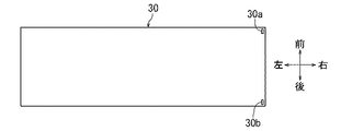
図8に示すように、太陽電池サブモジュール30の長手方向(左右方向)の一端側(例えば右端側)の前後の両端部には、前後一対の端子30a、30bが配置されている。例えば、前側の端子30aは−側端子であり、後側の端子30bは+側端子である。太陽電池サブモジュール30の長手方向の両端縁部は相互に平行をなし、その短手方向の両端縁部は相互に平行をなしている。
As shown in FIG. 8, a pair of front and
図7に示すように、ルーフパネル40は、その主体をなすパネル部材42と、パネル部材42の裏面側(下面側)に設けられた支持レール44とを有している。パネル部材42は、透光性を有する透明の樹脂、例えばポリカーボネート樹脂あるいはアクリル樹脂等により前後方向を長くする矩形板形状に形成されている。パネル部材42は、前後方向及び左右方向に関して表面側(上面側)に凸となる緩やかな湾曲形状に形成されている。パネル部材42は、太陽電池サブモジュール30の表面側(上面側)を覆うように配置されている。パネル部材42は、ルーフ12の窓開口部17(図6参照)を閉鎖するもので、ルーフ12の窓枠体16に嵌合可能に形成されている。なお、ルーフパネル40は本明細書でいう「パネル体」に相当する。
As shown in FIG. 7, the
支持レール44は、不透明性の着色樹脂、例えばガラス繊維やカーボンブラックが配合された黒色のポリカーボネート樹脂等により左右方向に延びる長尺状に形成されている。支持レール44は、パネル部材42の裏面(下面)に沿って形成されている。このため、支持レール44は、上側に凸となる緩やかな湾曲形状に形成されている。支持レール44は、前後方向に等間隔で複数本(例えば6本)配置されている。これにより、前後一対をなす両支持レール44を1組として計5組のレール対が構成されている。6本の支持レール44は、前後に平行又は略平行をなすように配置されている。
The
図5に示すように、支持レール44は、前後両側面に嵌合溝45を有する断面横向きH字状に形成されている。支持レール44は、上壁部44aと下壁部44bと両壁部44a,44bの中央部相互間を連結する連結壁44cとを有している。最前部の支持レール44は前側の嵌合溝45が省略されている(図3参照)。また、最後部の支持レール44は後側の嵌合溝45が省略されている(図4参照)。なお、支持レール44は本明細書でいう「支持部材」に相当する。また、嵌合溝45は本明細書でいう「嵌合部」に相当する。また、上壁部44aは嵌合溝45の上側の溝壁部に相当する。また、下壁部44bは嵌合溝45の下側の溝壁部に相当する。
As shown in FIG. 5, the
図7に示すように、ルーフパネル40のパネル部材42及び支持レール44は、一体成形、詳しくは二色成形により一体形成されている。また、パネル部材42が透明樹脂で成形されているとともに支持レール44が着色樹脂で一体成形されている。なお、支持レール44と同じ樹脂によりパネル部材42の裏面側の周縁部を縁取りすることでその周辺部をブラックアウト化してもよい。
As shown in FIG. 7, the
ルーフパネル40の各組の前後の両支持レール44の間には、それぞれ太陽電池サブモジュール30が配置されている。すなわち、両支持レール44の嵌合溝45には、太陽電池サブモジュール30の短手方向の両端縁部がスライドによって嵌合されている(図2〜図5参照)。これにより、計5組の両支持レール44の間にそれぞれ太陽電池サブモジュール30が支持されている。これにともない、太陽電池サブモジュール30は、上側に凸となる緩やかな湾曲形状に撓み変形されることにより、パネル部材の裏面側(下面側)に密着又は近接されている。また、隣接する太陽電池サブモジュール30の端子30a、30b(図8参照)は電気的に直列接続されている。最前部の太陽電池サブモジュール30の端子30a及び最後部の太陽電池サブモジュール30の端子30bは外部接続端子となる。このようにして、ルーフパネル40に太陽電池サブモジュール30がスライド方向に交差する方向(車両前後方向)に5個並置された太陽電池モジュール14が構成されている。
次に、車両のルーフ12に対する太陽電池モジュール14の設置について説明する。図1に示すように、太陽電池モジュール14のルーフパネル40のパネル部材42をルーフ12の窓枠体16の窓開口部17内にその上方から嵌合する。これにより、パネル部材42の周縁部(左右の両側縁部、前縁部及び後縁部)は、窓枠体16の両ルーフサイドレール18のパネル支持部18a、フロントヘッダ20のパネル支持部20a及びリヤヘッダ22のパネル支持部22a上に支持される(図2〜図4参照)。
Next, installation of the
パネル部材42の左右の両側縁部は、両ルーフサイドレール18のパネル支持部18a上に接着材47を介して接着されている(図2参照)。また、パネル部材42の前縁部は、ルーフ12のフロントヘッダ20のパネル支持部20a上に接着材48を介して接着されている(図3参照)。また、パネル部材42の後縁部は、ルーフ12のリヤヘッダ22のパネル支持部22a上に接着材49を介して接着されている(図4参照)。このようにして、パネル部材42の周縁部が車両のルーフ12の窓枠体16に装着されている。なお、パネル部材42の前縁部とフロントウィンドウシールド26の上縁部との対向端縁間には、その間の隙間を埋めるモール51が装着されている(図3参照)。
The left and right side edges of the
ルーフパネル40の最前部の支持レール44及び最後部の支持レール44を除いた中間部の支持レール44は、ルーフ12の各リインフォース24上に帯板状の緩衝材53を介して支持されている(図2及び図5参照)。また、ルーフパネル40の最前部の支持レール44は、フロントヘッダ20のレール支持部20b上に帯板状の緩衝材54を介して支持されている(図3参照)。また、ルーフパネル40の最後部の支持レール44は、リヤヘッダ22のレール支持部22b上に帯板状の緩衝材55を介して支持されている(図4参照)。各緩衝材53,54,55は、例えばゴム等の弾性材により形成されている。また、太陽電池モジュール14の前出の外部接続端子は車両の電気回路に電気的に接続されている。
The intermediate support rails 44 excluding the
前記した車両の太陽電池モジュール14において、車両の長期間(概ね10年)の使用後において、寿命の残存する太陽電池サブモジュール30をリサイクルしたい場合には、例えば、車両のルーフ12に対する太陽電池モジュール14の取付時とは逆順により、ルーフ12の窓枠体16から太陽電池モジュール14を取り外す。このとき、窓枠体16のルーフサイドレール18、フロントヘッダ20及びリヤヘッダ22とルーフパネル40のパネル部材42とを接着している接着材47,48,49は、カッターナイフ、回転カッター等の切断具(不図示)により切断する。又は、パネル部材42の周辺部を回転カッター等の切断具(不図示)により切断してもよい。
In the above-described vehicle
次に、太陽電池モジュール14から各太陽電池サブモジュール30をスライドによって取り外す(抜き外す)。これにより、各太陽電池サブモジュール30を容易に回収することができる。回収した太陽電池サブモジュール30は、新規の太陽電池モジュール14の太陽電池サブモジュール30として再利用することができる。なお、太陽電池モジュール14は、太陽電池サブモジュール30に損傷を与えることなく取り外せればよく、ルーフ12からの太陽電池モジュール14の取り外し方、太陽電池モジュール14からの太陽電池サブモジュール30の取り外し方は限定されない。
Next, each
前記した太陽電池モジュール14によると、太陽電池サブモジュール30を回収して新規の太陽電池モジュール14の太陽電池サブモジュール30として再利用することができる。これにより、太陽電池サブモジュール30のリサイクル性を向上することができる。また、太陽電池サブモジュール30は、太陽電池素子36を封止したものであるから、太陽電池素子36に対する防水性を有する。このため、太陽電池素子36に対する水分、汚れ等の異物の付着を考慮しなくて済むため、太陽電池サブモジュール30の取り扱い性がよい。
According to the
また、太陽電池サブモジュール30は撓み変形可能に形成されている。したがって、パネル部材42の各組の両支持レール44の嵌合溝45に対する太陽電池サブモジュール30の取付け(嵌合)及び取り外しに際して、太陽電池サブモジュール30の撓み変形を利用することができる。
Moreover, the
また、パネル部材42は表面側に凸となる湾曲形状に形成され、太陽電池サブモジュール30は撓み変形によりパネル部材42に密着又は近接されている。したがって、太陽電池サブモジュール30の中央部の自重による垂れ下がりを抑制することができる。
In addition, the
また、太陽電池サブモジュール30は矩形形状に形成され、各組の両支持レール44は、太陽電池サブモジュール30の一対の端縁部を支持するように配置され、支持レール44の嵌合溝45には、太陽電池サブモジュール30の一対の端縁部がスライド可能に嵌合されている。したがって、矩形形状に形成された太陽電池サブモジュール30を各組の両支持レール44に対してスライド操作によって容易に脱着することができる。また、太陽電池サブモジュール30の一対の端縁部に沿って延びる支持レール44の嵌合溝45に沿って太陽電池サブモジュール30の端縁部を容易にかつスムーズに嵌合させることができる。また、太陽電池サブモジュール30の撓み変形による弾性復元力により、支持レール44に対する太陽電池サブモジュール30のスライド方向への位置ずれを抑制することができる。
Further, the
また、パネル部材42には支持レール44が一体成形により形成されている。したがって、パネル部材42に支持レール44を固定するための固定手段(例えば、接着材、ねじ等)を省略することができる。
Further, a
また、ルーフパネル40の一体成形は二色成形又はアウトサート成形であり、支持レール44は不透光性の有色樹脂により形成されている。したがって、支持レール44を有色樹脂により一体形成することができる。これにより、パネル部材42の外観上に支持レール44を見え難くすることができる。
Further, the integral molding of the
前記した太陽電池モジュール14の支持構造において、ルーフパネル40のパネル部材42の周縁部は、車両のルーフ12の窓枠体16に装着されている。したがって、車両のルーフ12に太陽電池モジュール14を設置することができる。一般的に太陽電池素子36の寿命(概ね30年)に比べて車両の寿命(概ね10年)は短い。このように、車両のルーフ12に設置された太陽電池モジュール14によると、太陽電池サブモジュール30のリサイクルに好都合である。なお、窓枠体16にパネル部材42の周縁部をねじ止め、クリップ止め等の着脱可能な着脱手段を介して装着するとよい。
In the support structure of the
また、支持レール44は、パネル部材42を装着する窓枠体16に架設されたリインフォース24により下方より支持されている。したがって、窓枠体16に架設されたリインフォース24によって、窓枠体16を補強するとともに支持レール44を補強することができる。また、窓枠体16のフロントヘッダ20によって最前部の支持レール44が下方より支持されているとともにリヤヘッダ22によって最後部の支持レール44が下方より支持されているため、支持レール44を補強することができる。これにより、支持レール44による太陽電池モジュール14の支持を確実におこなうことができる。
Further, the
[実施形態2]
実施形態2を説明する。本実施形態は、実施形態1に変更を加えたものであるから、その変更部分について説明し、重複する説明は省略する。図10は太陽電池モジュールを設置した車両のルーフを示す平面図である。図10に示すように、本実施形態は、実施形態1における太陽電池サブモジュール30を、長手方向(左右方向)に2分割した太陽電池サブモジュール(符号、60を付す)としたものである。すなわち、ルーフパネル40に太陽電池サブモジュール60がスライド方向(車両左右方向)に2個ずつ並置されるとともにスライド方向に交差する方向(車両前後方向)に5列並置された計10個の太陽電池サブモジュール60を備える太陽電池モジュール14が構成されている。
[Embodiment 2]
A second embodiment will be described. Since the present embodiment is a modification of the first embodiment, the changed portion will be described and redundant description will be omitted. FIG. 10 is a plan view showing a roof of a vehicle in which a solar cell module is installed. As shown in FIG. 10, the present embodiment is a solar cell submodule (indicated by reference numeral 60) obtained by dividing the
図13は太陽電池サブモジュールを示す平面図である。図13に示すように、太陽電池サブモジュール60の長手方向(左右方向)の一端側(例えば左端側)の前後の両端部には一方の端子60aが配置されているとともにその他端側(例えば右端側)の前後の両端部には他方の端子60bが配置されている。一方の端子60aは例えば−側端子であり、他方の端子60bは例えば+側端子である。また、計10個の太陽電池サブモジュール60は電気的に直列接続されている。また、最前部の一方(例えば左側)の太陽電池サブモジュール30の端子30a及び最後部の他方(例えば右側)の太陽電池サブモジュール30の端子30bは外部接続端子となる。
FIG. 13 is a plan view showing the solar cell submodule. As shown in FIG. 13, one
図11は図10のXI−XI線矢視断面図、図12は図11のXII−XII線矢視断面図である。図11及び図12に示すように、支持レール44の嵌合溝45の下壁部44bには、太陽電池サブモジュール60の相互間すなわち支持レール44の長手方向の中央部において太陽電池サブモジュール60の端縁部の出し入れを可能とする切欠溝62が形成されている。なお、切欠溝62は本明細書でいう「開口部」に相当する。また、下壁部44bの上面は支持レール44の嵌合溝45の下側の嵌合面を形成している。
11 is a cross-sectional view taken along line XI-XI in FIG. 10, and FIG. 12 is a cross-sectional view taken along line XII-XII in FIG. As shown in FIGS. 11 and 12, the
本実施形態によると、支持レール44の長手方向に並置されかつスライド方向に隣接する両太陽電池サブモジュール60の対向端縁部を支持レール44の切欠溝62を通じて嵌合溝45に対して出し入れすることができる(図11中、矢印参照)。このことは、支持レール44の両端部側から太陽電池サブモジュール60の出し入れができない又はその出し入れが難しい場合等に有効である。例えば、ルーフ12にルーフパネル40を取付けたまま、そのルーフパネル40から太陽電池サブモジュール60を出し入れすることができる。また、太陽電池サブモジュール60の出し入れに際して、補強部材(フロントヘッダ20及びリヤヘッダ22並びにリインフォース24)及び緩衝材53,54,55が邪魔になる場合には、補強部材及び緩衝材53,54,55にも支持レール44の切欠溝62に対応する開口凹部を形成するか、嵌合溝45を補強部材に重ならないように外側に延出する位置に設ければよい。また、緩衝材53,54,55は弾性変形するため、その弾性変形により開口凹部を形成可能であれば、緩衝材に対する開口凹部の形成は不要である。また、太陽電池サブモジュール60は、スライド方向(左右方向)に3個以上並置してもよく、この場合、支持レール44の下壁部44bには、スライド方向に隣接する両太陽電池サブモジュール60の端縁部の出し入れを可能とする複数の切欠溝を形成すればよい。また、支持レール44を分割し、太陽電池サブモジュール60の端縁部の出し入れを可能とするだけの距離をおいて配置することで開口部を形成してもよい。
According to the present embodiment, the opposing edge portions of the
[他の技術的事項]
本発明は実施形態に限定されるものではなく、本発明の要旨を逸脱しない範囲における変更が可能である。例えば、パネル部材にはガラス板を用いてもよい。また、パネル部材は、半透明色でもよい。また、パネル部材は、単なる平板状に形成されたものでもよい。また、支持部材は、黒色以外の色でもよいし、半透明色あるいは透明でもよい。また、支持部材は、パネル部材にそのパネル部材と同一樹脂により一体成形により形成してもよい。また、パネル部材に支持レールを接着等の取付手段により取付けてもよい。また、パネル部材を支持レールの上壁部の代用とすれば、その上壁部を省略してもよい。また、支持レールに代えて、所定間隔毎に断続的に複数配置された支持部材を用いてもよい。また、フロントヘッダ20のレール支持部20bに代えて、フロントヘッダ20とは別に専用の補強部材を設定してもよい。また、リヤヘッダ22のレール支持部22bに代えて、リヤヘッダ22とは別に専用の補強部材を設定してもよい。また、補強部材はフロントヘッダ20及びリヤヘッダ22との間に架設されていてもよい。また、補強部材は省略してもよい。
[Other technical matters]
The present invention is not limited to the embodiments, and can be modified without departing from the gist of the present invention. For example, a glass plate may be used for the panel member. The panel member may be a translucent color. Further, the panel member may be formed in a simple flat plate shape. Further, the support member may be a color other than black, or may be a translucent color or transparent. Further, the support member may be formed on the panel member by integral molding with the same resin as the panel member. Moreover, you may attach a support rail to a panel member by attachment means, such as adhesion | attachment. Further, if the panel member is substituted for the upper wall portion of the support rail, the upper wall portion may be omitted. Moreover, it may replace with a support rail and may use the support member arrange | positioned intermittently for every predetermined space | interval. Further, instead of the
また、太陽電池サブモジュールは、少なくとも1つの太陽電池素子を備えていればよい。また、太陽電池サブモジュールは、1枚のパネル部材に対して少なくとも1枚設けられていればよい。また、太陽電池サブモジュールの表面材及び裏面材の層数、各層の材質等は適宜変更してもよい。また、支持部材の嵌合部に対する太陽電池サブモジュールの端縁部の嵌合は、実施形態のようなスライドによる嵌合に代え、パネル部材、支持部材及び太陽電池サブモジュールのうちの少なくとも1つの部材の弾性変形を利用して嵌合に対向する方向に着脱可能に嵌合してもよい。また、太陽電池サブモジュールは、撓み変形しない又は撓み変形しにくいものでもよい。また、太陽電池サブモジュールは、車両のルーフ以外の車体部分(例えばラッゲージコンパートメントドア、箱型トラックの荷台屋根等)、あるいは、車両以外の場所に設置してもよい。 Moreover, the solar cell submodule should just be provided with the at least 1 solar cell element. Further, it is sufficient that at least one solar cell submodule is provided for one panel member. Further, the number of layers of the surface material and the back material of the solar cell submodule, the material of each layer, and the like may be changed as appropriate. In addition, the fitting of the edge portion of the solar cell submodule to the fitting portion of the support member is replaced by the slide fitting as in the embodiment, and at least one of the panel member, the support member, and the solar cell submodule. You may detachably fit in the direction which opposes fitting using the elastic deformation of a member. Further, the solar cell submodule may be one that does not bend or hardly bend. Further, the solar cell sub-module may be installed in a vehicle body part other than the vehicle roof (for example, luggage compartment door, box truck roof, etc.), or in a place other than the vehicle.
12…ルーフ
14…太陽電池モジュール
16…窓枠体
18…ルーフサイドレール(枠材)
20…フロントヘッダ(枠材、補強部材)
22…リヤヘッダ(枠材、補強部材)
24…リインフォース(補強部材)
30…太陽電池サブモジュール
31…表面材
32…裏面材
36…太陽電池素子
42…パネル部材
44…支持レール(支持部材)
45…嵌合溝(嵌合部)
60…太陽電池サブモジュール
62…切欠溝(開口部)
12 ...
20 ... Front header (frame material, reinforcement member)
22 ... Rear header (frame material, reinforcement member)
24 ... Reinforce (Reinforcement member)
30 ...
45 ... Fitting groove (fitting part)
60 ...
Claims (10)
前記太陽電池サブモジュールにその表面側を覆うように配置される透光性を有する板形状のパネル部材と
を備え、
前記パネル部材には、前記太陽電池サブモジュールの端縁部を嵌合可能な嵌合部を有する複数の支持部材が設けられ、
前記複数の支持部材の嵌合部に前記太陽電池サブモジュールの端縁部を嵌合することにより前記パネル部材に前記太陽電池サブモジュールが着脱可能に支持されている
ことを特徴とする太陽電池モジュール。 A plate-shaped solar cell submodule formed by sealing a solar cell element between a front surface material and a back surface material into a submodule;
A plate-shaped panel member having translucency arranged so as to cover the surface side of the solar cell sub-module, and
The panel member is provided with a plurality of support members having fitting portions capable of fitting the edge portions of the solar cell submodule.
The solar cell submodule is detachably supported on the panel member by fitting an edge portion of the solar cell submodule to the fitting portions of the plurality of support members. .
前記太陽電池サブモジュールは撓み変形可能に形成されていることを特徴とする太陽電池モジュール。 The solar cell module according to claim 1,
The solar cell submodule is formed so as to be able to bend and deform.
前記パネル部材は表面側に凸となる湾曲形状に形成され、
前記太陽電池サブモジュールは撓み変形により前記パネル部材に密着又は近接されている
ことを特徴とする太陽電池モジュール。 The solar cell module according to claim 2, wherein
The panel member is formed in a curved shape that is convex on the surface side,
The solar cell submodule is in close contact with or close to the panel member by bending deformation.
前記太陽電池サブモジュールは矩形形状に形成され、
前記支持部材は、前記太陽電池サブモジュールの一対の端縁部を支持するように配置され、
前記支持部材の嵌合部には、前記太陽電池サブモジュールがスライド可能に嵌合されている
ことを特徴とする太陽電池モジュール。 It is a solar cell module according to any one of claims 1 to 3,
The solar cell submodule is formed in a rectangular shape,
The support member is arranged to support a pair of edge portions of the solar cell submodule,
The solar cell module, wherein the solar cell submodule is slidably fitted to the fitting portion of the support member.
前記支持部材は、前記太陽電池サブモジュールの一対の端縁部に沿って延びる嵌合部を有する支持レールであることを特徴とする太陽電池モジュール。 The solar cell module according to claim 4,
The solar cell module, wherein the support member is a support rail having a fitting portion extending along a pair of edge portions of the solar cell submodule.
前記太陽電池サブモジュールは前記支持レールの長手方向に複数並置され、
前記支持レールの嵌合部には、前記パネル部材とは反対側に開口する開口部が形成され、
前記支持レールの嵌合部に対して、スライド方向に隣接する前記両太陽電池サブモジュールを前記開口部を通じて出し入れ可能としている
ことを特徴とする太陽電池モジュール。 The solar cell module according to claim 5, wherein
A plurality of the solar cell submodules are juxtaposed in the longitudinal direction of the support rail,
The fitting portion of the support rail is formed with an opening that opens to the opposite side of the panel member,
The solar cell module, wherein the solar cell sub-modules adjacent to each other in the sliding direction with respect to the fitting portion of the support rail can be taken in and out through the opening.
前記パネル部材には前記支持部材が一体成形により形成されていることを特徴とする太陽電池モジュール。 The solar cell module according to any one of claims 1 to 6,
The solar cell module, wherein the panel member is formed with the support member by integral molding.
前記一体成形は二色成形又はアウトサート成形であり、前記支持部材は有色樹脂により形成されていることを特徴とする太陽電池モジュール。 The solar cell module according to claim 7, wherein
The integral molding is two-color molding or outsert molding, and the support member is formed of a colored resin.
前記支持部材は、前記パネル部材を装着する枠状部材により支持されている、または、前記枠状部材に架設された補強部材により支持されていることを特徴とする太陽電池モジュールの支持構造。 A support structure for a solar cell module according to any one of claims 1 to 8,
The support structure of the solar cell module, wherein the support member is supported by a frame-shaped member on which the panel member is mounted, or is supported by a reinforcing member laid on the frame-shaped member.
前記パネル部材の周縁部は、車両のルーフに設けられた窓枠体に装着されていることを特徴とする太陽電池モジュールの支持構造。 A support structure for a solar cell module according to any one of claims 1 to 9,
The peripheral structure of the panel member is attached to a window frame provided on a roof of a vehicle.
Priority Applications (1)
| Application Number | Priority Date | Filing Date | Title |
|---|---|---|---|
| JP2014105768A JP2015223012A (en) | 2014-05-22 | 2014-05-22 | Solar cell module |
Applications Claiming Priority (1)
| Application Number | Priority Date | Filing Date | Title |
|---|---|---|---|
| JP2014105768A JP2015223012A (en) | 2014-05-22 | 2014-05-22 | Solar cell module |
Publications (1)
| Publication Number | Publication Date |
|---|---|
| JP2015223012A true JP2015223012A (en) | 2015-12-10 |
Family
ID=54785765
Family Applications (1)
| Application Number | Title | Priority Date | Filing Date |
|---|---|---|---|
| JP2014105768A Pending JP2015223012A (en) | 2014-05-22 | 2014-05-22 | Solar cell module |
Country Status (1)
| Country | Link |
|---|---|
| JP (1) | JP2015223012A (en) |
Cited By (3)
| Publication number | Priority date | Publication date | Assignee | Title |
|---|---|---|---|---|
| WO2018101193A1 (en) * | 2016-11-29 | 2018-06-07 | 京セラ株式会社 | Solar cell device |
| WO2018150794A1 (en) * | 2017-02-17 | 2018-08-23 | パナソニックIpマネジメント株式会社 | Solar cell module |
| CN111614311A (en) * | 2020-05-23 | 2020-09-01 | 宁波锦锐能源科技有限公司 | A solar panel mounting frame for home roof photovoltaic engineering |
Citations (10)
| Publication number | Priority date | Publication date | Assignee | Title |
|---|---|---|---|---|
| JPS6285743A (en) * | 1985-10-12 | 1987-04-20 | Nissan Motor Co Ltd | Solar cell plate setting structure for automobile |
| JPS6444216U (en) * | 1987-09-11 | 1989-03-16 | ||
| JPH0520348U (en) * | 1991-08-23 | 1993-03-12 | 三洋電機株式会社 | Solar cell generator |
| JPH0575016U (en) * | 1992-03-18 | 1993-10-12 | 矢崎総業株式会社 | Mounting structure for automobile solar cell sheet |
| JPH10317622A (en) * | 1997-05-22 | 1998-12-02 | Sekisui Chem Co Ltd | Panel roof structure with solar cells, roof panel used for the roof structure, and connecting member |
| WO2010106767A1 (en) * | 2009-03-17 | 2010-09-23 | ダイキョーニシカワ株式会社 | Sunshade structure |
| JP2012033573A (en) * | 2010-07-28 | 2012-02-16 | Mazda Motor Corp | On-vehicle solar cell panel and mounting structure thereof |
| US20120255596A1 (en) * | 2011-04-05 | 2012-10-11 | General Electric Company | Photovoltaic mounting system with grounding bars and method of installing same |
| JP2013177088A (en) * | 2012-02-29 | 2013-09-09 | Yachiyo Industry Co Ltd | Mounting structure for film-shaped electric device |
| WO2013182399A1 (en) * | 2012-06-05 | 2013-12-12 | Saint-Gobain Glass France | Sunroof comprising an integrated photovoltaic module |
-
2014
- 2014-05-22 JP JP2014105768A patent/JP2015223012A/en active Pending
Patent Citations (10)
| Publication number | Priority date | Publication date | Assignee | Title |
|---|---|---|---|---|
| JPS6285743A (en) * | 1985-10-12 | 1987-04-20 | Nissan Motor Co Ltd | Solar cell plate setting structure for automobile |
| JPS6444216U (en) * | 1987-09-11 | 1989-03-16 | ||
| JPH0520348U (en) * | 1991-08-23 | 1993-03-12 | 三洋電機株式会社 | Solar cell generator |
| JPH0575016U (en) * | 1992-03-18 | 1993-10-12 | 矢崎総業株式会社 | Mounting structure for automobile solar cell sheet |
| JPH10317622A (en) * | 1997-05-22 | 1998-12-02 | Sekisui Chem Co Ltd | Panel roof structure with solar cells, roof panel used for the roof structure, and connecting member |
| WO2010106767A1 (en) * | 2009-03-17 | 2010-09-23 | ダイキョーニシカワ株式会社 | Sunshade structure |
| JP2012033573A (en) * | 2010-07-28 | 2012-02-16 | Mazda Motor Corp | On-vehicle solar cell panel and mounting structure thereof |
| US20120255596A1 (en) * | 2011-04-05 | 2012-10-11 | General Electric Company | Photovoltaic mounting system with grounding bars and method of installing same |
| JP2013177088A (en) * | 2012-02-29 | 2013-09-09 | Yachiyo Industry Co Ltd | Mounting structure for film-shaped electric device |
| WO2013182399A1 (en) * | 2012-06-05 | 2013-12-12 | Saint-Gobain Glass France | Sunroof comprising an integrated photovoltaic module |
Cited By (4)
| Publication number | Priority date | Publication date | Assignee | Title |
|---|---|---|---|---|
| WO2018101193A1 (en) * | 2016-11-29 | 2018-06-07 | 京セラ株式会社 | Solar cell device |
| JPWO2018101193A1 (en) * | 2016-11-29 | 2019-10-24 | 京セラ株式会社 | Solar cell device |
| WO2018150794A1 (en) * | 2017-02-17 | 2018-08-23 | パナソニックIpマネジメント株式会社 | Solar cell module |
| CN111614311A (en) * | 2020-05-23 | 2020-09-01 | 宁波锦锐能源科技有限公司 | A solar panel mounting frame for home roof photovoltaic engineering |
Similar Documents
| Publication | Publication Date | Title |
|---|---|---|
| US9278617B2 (en) | Solar battery mounting structure for vehicle | |
| JP5907150B2 (en) | Vehicle roof structure and vehicle, and method for manufacturing vehicle roof unit | |
| JP5494334B2 (en) | In-vehicle solar panel mounting structure | |
| US6034320A (en) | Sunshine roof panel for a vehicle | |
| JP5835375B2 (en) | Solar cell mounting structure | |
| US20110226312A1 (en) | Vehicle surface component having a solar cell arrangement | |
| JP6491071B2 (en) | In-vehicle solar cell module | |
| US9242554B2 (en) | Vehicle roof structure | |
| US8952236B2 (en) | Hybrid type roof panel having solar cell | |
| WO2003041980A3 (en) | Glass cover for a vehicle roof and production method therefor | |
| JP2015223012A (en) | Solar cell module | |
| KR101437438B1 (en) | Solarcell module for weight lightening | |
| CN110691699A (en) | Vehicle sunroof with covered lighting | |
| JP6391929B2 (en) | Solar cell module | |
| JP6365896B2 (en) | Solar cell module | |
| JP2019047631A (en) | Method for loading resin solar roof module | |
| JP6985133B2 (en) | Solar cell module | |
| JPH0580379B2 (en) | ||
| JP2021016278A (en) | On-vehicle solar cell module | |
| JP6325898B2 (en) | Solar cell module and frame for solar cell module | |
| JP2015120429A (en) | Vehicle solar battery mounting structure | |
| JP7247789B2 (en) | double glazing structure for vehicle | |
| JP6835610B2 (en) | Body superstructure | |
| JP2019043377A (en) | Mounting structure of resin solar roof module | |
| JP2025073316A (en) | Solar panel fixing structure |
Legal Events
| Date | Code | Title | Description |
|---|---|---|---|
| A621 | Written request for application examination |
Free format text: JAPANESE INTERMEDIATE CODE: A621 Effective date: 20160907 |
|
| A977 | Report on retrieval |
Free format text: JAPANESE INTERMEDIATE CODE: A971007 Effective date: 20170517 |
|
| A131 | Notification of reasons for refusal |
Free format text: JAPANESE INTERMEDIATE CODE: A131 Effective date: 20170606 |
|
| A521 | Request for written amendment filed |
Free format text: JAPANESE INTERMEDIATE CODE: A523 Effective date: 20170802 |
|
| A131 | Notification of reasons for refusal |
Free format text: JAPANESE INTERMEDIATE CODE: A131 Effective date: 20170912 |
|
| A02 | Decision of refusal |
Free format text: JAPANESE INTERMEDIATE CODE: A02 Effective date: 20180306 |