JP2015142325A - Distortion compensation apparatus and distortion compensation method - Google Patents
Distortion compensation apparatus and distortion compensation method Download PDFInfo
- Publication number
- JP2015142325A JP2015142325A JP2014015581A JP2014015581A JP2015142325A JP 2015142325 A JP2015142325 A JP 2015142325A JP 2014015581 A JP2014015581 A JP 2014015581A JP 2014015581 A JP2014015581 A JP 2014015581A JP 2015142325 A JP2015142325 A JP 2015142325A
- Authority
- JP
- Japan
- Prior art keywords
- signal
- frequency band
- component
- power amplifier
- lpf
- Prior art date
- Legal status (The legal status is an assumption and is not a legal conclusion. Google has not performed a legal analysis and makes no representation as to the accuracy of the status listed.)
- Pending
Links
Images


Classifications
-
- H—ELECTRICITY
- H03—ELECTRONIC CIRCUITRY
- H03F—AMPLIFIERS
- H03F1/00—Details of amplifiers with only discharge tubes, only semiconductor devices or only unspecified devices as amplifying elements
- H03F1/32—Modifications of amplifiers to reduce non-linear distortion
- H03F1/3241—Modifications of amplifiers to reduce non-linear distortion using predistortion circuits
- H03F1/3247—Modifications of amplifiers to reduce non-linear distortion using predistortion circuits using feedback acting on predistortion circuits
-
- H—ELECTRICITY
- H03—ELECTRONIC CIRCUITRY
- H03F—AMPLIFIERS
- H03F1/00—Details of amplifiers with only discharge tubes, only semiconductor devices or only unspecified devices as amplifying elements
- H03F1/32—Modifications of amplifiers to reduce non-linear distortion
- H03F1/3241—Modifications of amplifiers to reduce non-linear distortion using predistortion circuits
- H03F1/3258—Modifications of amplifiers to reduce non-linear distortion using predistortion circuits based on polynomial terms
-
- H—ELECTRICITY
- H03—ELECTRONIC CIRCUITRY
- H03F—AMPLIFIERS
- H03F3/00—Amplifiers with only discharge tubes or only semiconductor devices as amplifying elements
- H03F3/189—High-frequency amplifiers, e.g. radio frequency amplifiers
- H03F3/19—High-frequency amplifiers, e.g. radio frequency amplifiers with semiconductor devices only
-
- H—ELECTRICITY
- H03—ELECTRONIC CIRCUITRY
- H03F—AMPLIFIERS
- H03F3/00—Amplifiers with only discharge tubes or only semiconductor devices as amplifying elements
- H03F3/20—Power amplifiers, e.g. Class B amplifiers, Class C amplifiers
- H03F3/24—Power amplifiers, e.g. Class B amplifiers, Class C amplifiers of transmitter output stages
- H03F3/245—Power amplifiers, e.g. Class B amplifiers, Class C amplifiers of transmitter output stages with semiconductor devices only
-
- H—ELECTRICITY
- H03—ELECTRONIC CIRCUITRY
- H03F—AMPLIFIERS
- H03F2200/00—Indexing scheme relating to amplifiers
- H03F2200/102—A non-specified detector of a signal envelope being used in an amplifying circuit
-
- H—ELECTRICITY
- H03—ELECTRONIC CIRCUITRY
- H03F—AMPLIFIERS
- H03F2200/00—Indexing scheme relating to amplifiers
- H03F2200/451—Indexing scheme relating to amplifiers the amplifier being a radio frequency amplifier
-
- H—ELECTRICITY
- H03—ELECTRONIC CIRCUITRY
- H03F—AMPLIFIERS
- H03F2201/00—Indexing scheme relating to details of amplifiers with only discharge tubes, only semiconductor devices or only unspecified devices as amplifying elements covered by H03F1/00
- H03F2201/32—Indexing scheme relating to modifications of amplifiers to reduce non-linear distortion
- H03F2201/3227—Adaptive predistortion based on amplitude, envelope or power level feedback from the output of the main amplifier
Landscapes
- Engineering & Computer Science (AREA)
- Power Engineering (AREA)
- Physics & Mathematics (AREA)
- Nonlinear Science (AREA)
- Algebra (AREA)
- General Physics & Mathematics (AREA)
- Mathematical Analysis (AREA)
- Mathematical Optimization (AREA)
- Pure & Applied Mathematics (AREA)
- Amplifiers (AREA)
Abstract
Description
本発明は歪補償装置および歪補償方法に関する。 The present invention relates to a distortion compensation apparatus and a distortion compensation method.
無線通信システムにおいて無線信号を送信する無線送信装置では、送信信号を増幅するために電力増幅器が用いられる。電力増幅器は、入力信号の振幅が小さい領域では、入力信号の振幅と出力信号の振幅とが概ね線形な関係になるという線形特性を有する。一方、電力増幅器は、入力信号の振幅が大きい領域では、入力信号の振幅と出力信号の振幅とが非線形な関係になるという非線形特性を有する。電力増幅器を効率的に利用するために、線形領域だけでなく非線形領域でも電力増幅器を動作させることが多い。 In a wireless transmission device that transmits a wireless signal in a wireless communication system, a power amplifier is used to amplify the transmission signal. The power amplifier has a linear characteristic that the amplitude of the input signal and the amplitude of the output signal have a substantially linear relationship in a region where the amplitude of the input signal is small. On the other hand, the power amplifier has a nonlinear characteristic that the amplitude of the input signal and the amplitude of the output signal have a nonlinear relationship in a region where the amplitude of the input signal is large. In order to use the power amplifier efficiently, the power amplifier is often operated not only in the linear region but also in the nonlinear region.
しかし、電力増幅器の非線形な増幅特性によって発生する送信信号の非線形歪は、所望の周波数帯域から隣接周波数帯域への電力漏洩を生じさせるなど、無線通信品質を低下させる原因となり得る。そこで、無線送信装置は、電力増幅器の非線形な増幅特性を線形化(リニアライズ)する1つの方法として、前置歪(プリディストーション)方式の歪補償を行うことがある。プリディストーション方式の歪補償では、無線送信装置に、線形化器(リニアライザ)として前置歪器(プリディストータ)を設ける。 However, the non-linear distortion of the transmission signal generated by the non-linear amplification characteristic of the power amplifier can cause the wireless communication quality to deteriorate, for example, power leakage from a desired frequency band to an adjacent frequency band occurs. Therefore, the wireless transmission apparatus may perform predistortion type distortion compensation as one method for linearizing the nonlinear amplification characteristics of the power amplifier. In predistortion type distortion compensation, a predistorter (predistorter) is provided as a linearizer in a wireless transmission device.
プリディストータは、電力増幅器に入力する入力信号に、電力増幅器の非線形特性とは逆の非線形歪を付与する。例えば、プリディストータは、各入力信号に対して当該入力信号のレベルに応じた利得を与える。逆特性の非線形歪が付与された入力信号を電力増幅器に通すことで、増幅された送信信号の非線形歪を抑制できる。ただし、電力増幅器の逆特性を予め正確に推定することは容易でない。そこで、電力増幅器を動作させながら、プリディストータが使用する補償係数を学習する(補償係数を更新する)ことがある。 The predistorter imparts non-linear distortion opposite to the non-linear characteristic of the power amplifier to the input signal input to the power amplifier. For example, the predistorter gives a gain corresponding to the level of the input signal to each input signal. By passing the input signal to which the nonlinear distortion having the reverse characteristic is passed through the power amplifier, the nonlinear distortion of the amplified transmission signal can be suppressed. However, it is not easy to accurately estimate the inverse characteristics of the power amplifier in advance. Therefore, there is a case where the compensation coefficient used by the predistorter is learned (the compensation coefficient is updated) while operating the power amplifier.
プリディストータの実装方法としては、多項式法やLUT(Lookup Table)法が提案されている。多項式法では、電力増幅器の逆特性が、入力信号のレベルを示す変数と複数の係数とを含む多項式として表現される。LUT法では、電力増幅器の逆特性が、入力信号のレベルと当該入力信号に与える利得とを対応付けたテーブルとして表現される。 As a predistorter mounting method, a polynomial method or a LUT (Lookup Table) method has been proposed. In the polynomial method, the inverse characteristic of the power amplifier is expressed as a polynomial including a variable indicating a level of an input signal and a plurality of coefficients. In the LUT method, the inverse characteristic of the power amplifier is expressed as a table in which the level of the input signal is associated with the gain applied to the input signal.
プリディストータで使用する補償係数の学習方法としては、直接学習法や間接学習法やモデル−インバース法が提案されている。直接学習法では、電力増幅器からのフィードバック信号と歪補償を行う前の入力信号とを比較し、両者の誤差が小さくなるように補償係数を更新する。間接学習法では、電力増幅器からのフィードバック信号に対して補償係数を適用するトレーニング用ディストータを設け、歪補償を行った後の入力信号とトレーニング用ディストータの出力との誤差が小さくなるように補償係数を更新する。トレーニング用ディストータで学習された補償係数がプリディストータにコピーされる。モデル−インバース法では、歪補償を行った後の入力信号に対して電力増幅器のモデルを適用するモデリング部を設け、電力増幅器からのフィードバック信号とモデリング部の出力との誤差が小さくなるようにモデルを更新する。そして、モデリング部で学習されたモデルの逆特性(逆モデル)を示す補償係数を算出し、プリディストータに設定する。 As a learning method of the compensation coefficient used in the predistorter, a direct learning method, an indirect learning method, and a model-inverse method have been proposed. In the direct learning method, the feedback signal from the power amplifier is compared with the input signal before distortion compensation, and the compensation coefficient is updated so that the error between the two becomes small. In the indirect learning method, a training distorter that applies a compensation coefficient to the feedback signal from the power amplifier is provided, so that the error between the input signal after distortion compensation and the output of the training distorter is reduced. Update. The compensation coefficient learned by the training distorter is copied to the predistorter. In the model-inverse method, a modeling unit that applies a power amplifier model to the input signal after distortion compensation is provided, and the model is configured so that the error between the feedback signal from the power amplifier and the output of the modeling unit is reduced. Update. Then, a compensation coefficient indicating the inverse characteristic (inverse model) of the model learned by the modeling unit is calculated and set in the predistorter.
ところで、電力増幅器からフィードバック信号を得るフィードバックパスには、アナログデジタル変換器(ADC:Analog to Digital Converter)などの各種の信号処理ユニットが含まれ得る。フィードバックパスを通過するフィードバック信号の帯域幅が大きいと、補償係数を学習するときの負荷が高くなる、高性能な信号処理ユニットを使用するためにコストが大きくなるなどの不利益が生じ得る。そこで、フィードバックパスに低域通過フィルタ(LPF:Low Pass Filter)を設けたリニアライザが提案されている。このリニアライザは、LPFを用いて高周波成分をカットすることで、電力増幅器が出力する送信信号と比べてフィードバック信号の帯域幅を制限し、帯域幅が制限されたフィードバック信号に基づいて電力増幅器の逆特性を示す補償係数を学習する。 By the way, the feedback path for obtaining the feedback signal from the power amplifier may include various signal processing units such as an analog-to-digital converter (ADC). If the bandwidth of the feedback signal passing through the feedback path is large, there may be disadvantages such as a high load when learning the compensation coefficient and a high cost for using a high-performance signal processing unit. Thus, a linearizer has been proposed in which a low pass filter (LPF) is provided in the feedback path. This linearizer uses LPF to cut high-frequency components, thereby limiting the bandwidth of the feedback signal compared to the transmission signal output from the power amplifier, and reverses the power amplifier based on the feedback signal with the bandwidth limited. A compensation coefficient indicating characteristics is learned.
上記のように、高周波成分をカットしたフィードバック信号を用いて補償係数を学習する学習方法が提案されている。しかし、帯域幅を制限するために単純に一部の周波数帯域の成分をカットしてしまうと、その周波数帯域に存在する歪が考慮されなくなってしまう。よって、上記の学習方法では、補償係数の学習精度に改善の余地がある。 As described above, a learning method for learning a compensation coefficient using a feedback signal from which a high-frequency component has been cut has been proposed. However, if a component of a part of the frequency band is simply cut to limit the bandwidth, the distortion existing in that frequency band will not be considered. Therefore, in the above learning method, there is room for improvement in the learning accuracy of the compensation coefficient.
1つの側面では、本発明は、フィードバック信号の帯域幅を制限した場合の学習精度を向上させる歪補償装置および歪補償方法を提供することを目的とする。 In one aspect, an object of the present invention is to provide a distortion compensation apparatus and a distortion compensation method that improve learning accuracy when the bandwidth of a feedback signal is limited.
1つの態様では、プリディストータと帯域制限部と学習部とを有する歪補償装置が提供される。プリディストータは、電力増幅器に入力する入力信号に補償係数に応じた歪を付与する。帯域制限部は、電力増幅器からフィードバックされるフィードバック信号のうち第1の周波数帯域以外の第2の周波数帯域の成分を制限し、また、制限される第2の周波数帯域の成分に応じて第1の周波数帯域の成分を変形する。学習部は、変形されたフィードバック信号に基づいて補償係数を更新する。 In one aspect, a distortion compensation apparatus having a predistorter, a band limiting unit, and a learning unit is provided. The predistorter imparts distortion corresponding to the compensation coefficient to the input signal input to the power amplifier. The band limiting unit limits the component of the second frequency band other than the first frequency band in the feedback signal fed back from the power amplifier, and also sets the first according to the component of the second frequency band to be limited. The frequency band component of is deformed. The learning unit updates the compensation coefficient based on the transformed feedback signal.
また、1つの態様では、プリディストータを用いて電力増幅器で生じる歪を補償する歪補償方法が提供される。歪補償方法では、電力増幅器からフィードバックされるフィードバック信号のうち第1の周波数帯域以外の第2の周波数帯域の成分を制限し、また、制限される第2の周波数帯域の成分に応じて第1の周波数帯域の成分を変形する。変形されたフィードバック信号に基づいて、電力増幅器に入力する入力信号に対してプリディストータが使用する補償係数を更新する。 In one aspect, a distortion compensation method for compensating for distortion generated in a power amplifier using a predistorter is provided. In the distortion compensation method, the component of the second frequency band other than the first frequency band in the feedback signal fed back from the power amplifier is limited, and the first frequency is determined according to the component of the second frequency band to be limited. The frequency band component of is deformed. Based on the transformed feedback signal, the compensation coefficient used by the predistorter is updated for the input signal input to the power amplifier.
1つの側面では、フィードバック信号の帯域幅を制限した場合の学習精度が向上する。 In one aspect, learning accuracy is improved when the bandwidth of the feedback signal is limited.
以下、本実施の形態を図面を参照して説明する。
[第1の実施の形態]
図1は、第1の実施の形態の歪補償装置の例を示す図である。
Hereinafter, the present embodiment will be described with reference to the drawings.
[First Embodiment]
FIG. 1 is a diagram illustrating an example of the distortion compensation apparatus according to the first embodiment.
第1の実施の形態の歪補償装置10は、電力増幅器2の非線形歪を補償する。この非線形歪は、電力増幅器2の入力信号のレベルと出力信号のレベルとの関係(増幅特性)が非線形であるために、電力増幅器2の出力信号に生じる歪である。電力増幅器2は、高出力増幅器(HPA:High Power Amplifier)と呼ばれるものでもよい。電力増幅器2および歪補償装置10は、例えば、無線信号を送信する無線送信装置に搭載される。無線送信装置としては、例えば、無線基地局、無線中継装置、無線端末装置などが挙げられる。
The
歪補償装置10は、プリディストータ11と帯域制限部12と学習部13を有する。
プリディストータ11は、電力増幅器2に入力される入力信号に補償係数に応じた歪を付与する。プリディストータ11が付与する歪は、好ましくは、電力増幅器2で生じる非線形歪を打ち消すような電力増幅器2の逆特性をもつ歪である。プリディストータ11が使用する補償係数は、後述するように、学習部13による学習を通じて算出される。補償係数は、多項式に含まれる係数であってもよく、入力信号のレベルと対応付けてルックアップテーブル(LUT)に記憶される係数であってもよい。電力増幅器2の逆特性を示す多項式は、電力増幅器2がもつメモリ効果を考慮してもよいし考慮しなくてもよい。
The
The
帯域制限部12は、電力増幅器2から学習部13へフィードバック信号を伝送するフィードバックパス上に設けられ、フィードバック信号の帯域幅を電力増幅器2の出力信号よりも小さくなるように制限する。帯域制限部12は、周波数帯域14(第1の周波数帯域)の成分は制限せず、周波数帯域15(第2の周波数帯域)の成分を制限する。例えば、周波数帯域14は所定周波数以下の低周波帯域であり、周波数帯域15は周波数帯域14から外れた高周波帯域である。周波数帯域15の成分は、できる限りフィードバック信号からカットされることが好ましい。例えば、帯域制限部12は、低域通過フィルタ(LPF)を用いて、フィードバック信号から周波数帯域15の成分をカットする。
The
また、帯域制限部12は、周波数帯域15の成分に応じて周波数帯域14の成分を変形する。例えば、帯域制限部12は、フィードバック信号に含まれる周波数帯域15の成分を周波数帯域14に属する信号に変換し、フィードバック信号に含まれる元の周波数帯域14の成分と合成する。変換前の周波数帯域15の成分と変換後の周波数帯域14の信号との間には、相関があることが好ましい。この異なる周波数間の変換は、非線形変換であり、包絡線検波器や絶対値関数などの非線形ユニットを用いて実現できる。
Further, the
これにより、帯域制限部12を通過するフィードバック信号には、電力増幅器2の出力信号に含まれる周波数帯域14の成分の特徴に加えて、帯域制限部12により制限された周波数帯域15の成分の特徴が反映される。帯域制限部12は、周波数帯域14の成分を通過させ周波数帯域15の成分を制限するフィルタと、周波数帯域15から周波数帯域14に信号を変換する非線形ユニットとを有していてもよい。例えば、帯域制限部12は、LPFと、高周波帯域から低周波帯域に信号を変換する包絡線検波器を有する。
As a result, the feedback signal passing through the
学習部13は、帯域制限部12を通過したフィードバック信号を取得し、取得したフィードバック信号に基づいてプリディストータ11が使用する補償係数を更新する。補償係数の学習方法として、モデル−インバース法を用いてもよい。モデル−インバース法によれば、学習部13は、以下のようにして補償係数を学習することができる。
The
例えば、歪補償装置10は、プリディストータ11で歪が付与された入力信号から、フィードバック信号と比較される参照信号を生成するフォワードパスを有する。参照信号は、電力増幅器2の増幅特性のモデルに基づいて入力信号を変換することで生成される。学習部13は、フィードバック信号と参照信号とを比較し、誤差が小さくなるようにモデルを更新していく。学習部13は、更新されたモデルの逆特性(逆モデル)を示す補償係数を算出することで、プリディストータ11が使用する補償係数を更新する。
For example, the
フィードバック信号と参照信号とを比較するにあたり、フォワードパス上に帯域制限部12に対応する他の帯域制限部を設けてもよい。例えば、他の帯域制限部は、参照信号のうち周波数帯域14の成分を制限せず周波数帯域15の成分を制限する。また、他の帯域制限部は、制限される周波数帯域15の成分に応じて、参照信号のうち周波数帯域14の成分を変形する。この場合、学習部13は、帯域制限部12により変形されたフィードバック信号と他の帯域制限部により変形された参照信号とを比較して誤差を判定する。
In comparing the feedback signal and the reference signal, another band limiting unit corresponding to the
第1の実施の形態の歪補償装置10によれば、電力増幅器2から学習部13へフィードバックされるフィードバック信号の帯域幅が、帯域制限部12によって制限される。これにより、歪補償装置10の負荷を削減でき、また、ADCなどの各種の信号処理ユニットのコストを抑えることができる。また、歪補償装置10によれば、帯域制限部12によって制限される周波数帯域15の成分に応じて、帯域制限部12を通過する周波数帯域14の成分が変形される。これにより、学習部13は、周波数帯域15で生じた歪など、帯域制限部12によってカットされ得る周波数帯域15の成分の特徴も考慮して、補償係数を学習することができる。よって、補償係数の学習精度が向上する。
According to the
[第2の実施の形態]
図2は、第2の実施の形態の無線通信システムの例を示す図である。
第2の実施の形態の無線通信システムは、無線送信装置100および無線受信装置200を有する。無線送信装置100は、アンテナ111を有し、アンテナ111を用いて無線受信装置200に対して無線信号を送信する。無線受信装置200は、アンテナ211を有し、アンテナ211を用いて無線送信装置100から無線信号を受信する。
[Second Embodiment]
FIG. 2 is a diagram illustrating an example of a wireless communication system according to the second embodiment.
The wireless communication system according to the second embodiment includes a
第2の実施の形態では、主に無線送信装置100の送信処理について説明する。ただし、無線送信装置100に相当する無線通信装置が更に受信処理を行ってもよいし、無線受信装置200に相当する無線通信装置が更に送信処理を行ってもよい。また、この無線通信システムは、無線基地局が複数の無線端末装置と通信する1対多接続型のシステムであってもよい。その場合、例えば、無線送信装置100が無線基地局であり、無線受信装置200が無線端末装置であってもよい。また、例えば、無線送信装置100が無線端末装置であり、無線受信装置200が無線基地局であってもよい。また、無線送信装置100と無線受信装置200の少なくとも一方が、無線中継装置であってもよい。
In the second embodiment, transmission processing of the
後述するように、無線送信装置100は、送信信号を増幅する電力増幅器と電力増幅器で生じる非線形歪を補償するプリディストータとを有する。プリディストータは、電力増幅器に入力される入力信号に対して電力増幅器とは逆の非線形歪を付与する。このとき、プリディストータでは電力増幅器の逆の非線形性を示す補償係数が使用される。無線送信装置100は、電力増幅器から取得するフィードバック信号に基づいて、プリディストータの補償係数を適応的に変更することができる。次に、電力増幅器の非線形な増幅特性およびプリディストータが入力信号に付与する非線形歪について説明する。
As will be described later, the
図3は、電力増幅器およびプリディストータの特性例を示すグラフである。
電力増幅器の増幅特性は、入力信号の振幅が小さい領域ではほぼ線形になる(線形領域)。すなわち、入力信号の振幅が小さいうちは増幅率がほぼ一定となり、入力信号の振幅と出力信号の振幅とが線形の関係になる。一方、電力増幅器の増幅特性は、入力信号の振幅が大きい領域では非線形になる(非線形領域)。すなわち、入力信号の振幅が大きくなると、増幅率が一定とならずに入力信号の振幅に応じて変化し、入力信号の振幅と出力信号の振幅とが非線形の関係になる。通常、非線形領域では線形領域よりも増幅率が小さくなり、入力信号の振幅が大きいほど増幅率が減少する。無線送信装置100が備える電力増幅器には、非線形領域に属するような入力信号も入力され得る。
FIG. 3 is a graph showing an example of characteristics of the power amplifier and the predistorter.
The amplification characteristic of the power amplifier is almost linear in a region where the amplitude of the input signal is small (linear region). That is, while the amplitude of the input signal is small, the amplification factor is substantially constant, and the amplitude of the input signal and the amplitude of the output signal have a linear relationship. On the other hand, the amplification characteristic of the power amplifier is non-linear in a region where the amplitude of the input signal is large (non-linear region). That is, when the amplitude of the input signal increases, the amplification factor does not become constant but changes according to the amplitude of the input signal, and the amplitude of the input signal and the amplitude of the output signal have a non-linear relationship. Usually, the amplification factor is smaller in the nonlinear region than in the linear region, and the amplification factor decreases as the amplitude of the input signal increases. An input signal belonging to the nonlinear region can also be input to the power amplifier included in the
プリディストータは、好ましくは、電力増幅器の増幅率の非線形性を打ち消して線形化するように入力信号を歪ませる。プリディストータの利得は、入力信号の振幅が小さい領域では、電力増幅器と同様にほぼ線形になる(線形領域)。線形領域では、出力信号の振幅は入力信号の振幅とほぼ同じでもよい。一方、プリディストータの利得は、入力信号の振幅が大きい領域では、電力増幅器の増幅率の変化に合わせて非線形になる(非線形領域)。非線形領域では、電力増幅器とは逆に線形領域よりも利得が大きくなり、入力信号の振幅が大きいほど利得が増加する。すなわち、プリディストータは、非線形領域における電力増幅器の増幅率の低下を補うように、入力信号に利得を与える。 The predistorter preferably distorts the input signal so as to cancel and linearize the nonlinearity of the amplification factor of the power amplifier. The gain of the predistorter is substantially linear (linear region) in the region where the amplitude of the input signal is small, like the power amplifier. In the linear region, the amplitude of the output signal may be approximately the same as the amplitude of the input signal. On the other hand, the gain of the predistorter becomes nonlinear (nonlinear region) in accordance with the change in the amplification factor of the power amplifier in a region where the amplitude of the input signal is large. In the non-linear region, contrary to the power amplifier, the gain is larger than that in the linear region, and the gain increases as the amplitude of the input signal increases. That is, the predistorter gives a gain to the input signal so as to compensate for the decrease in the amplification factor of the power amplifier in the nonlinear region.
図4は、無線送信装置の例を示すブロック図である。
無線送信装置100は、デジタルプリディストータ(DPD:Digital Predistorter)112、電力増幅器113、減衰器114、複合LPF115,117、HPAモデリング部116、減算器118および逆モデル算出部119を有する。なお、DPD112は、第1の実施の形態のプリディストータ11の一例である。電力増幅器113は、第1の実施の形態の電力増幅器2の一例である。複合LPF115は、第1の実施の形態の帯域制限部12の一例である。HPAモデリング部116、減算器118および逆モデル算出部119の集合は、第1の実施の形態の学習部13の一例である。
FIG. 4 is a block diagram illustrating an example of a wireless transmission device.
The
DPD112は、電力増幅器113に入力する入力信号に対して、デジタル方式で歪補償を行うプリディストータである。DPD112は、歪補償に用いる補償係数の集合を保持している。DPD112は、補償係数を記憶する揮発性または不揮発性のメモリを有してもよい。例えば、DPD112は、元の入力信号のレベル(振幅や電力値など)と歪補償後のレベル(振幅や電力値など)との対応関係を表した多項式を用いて、各入力信号に与える利得を決定する。多項式は、入力信号のレベルを示す変数と補償係数とを含む。電力増幅器113のメモリ効果が顕著である場合、すなわち、電力増幅器113の増幅率が現在の入力信号のレベルに加えて過去の入力信号のレベルにも依存する場合、多項式は、所定個数前の入力信号のレベルを示す変数を含んでもよい。ただし、DPD112は、補償係数を格納したルックアップテーブル(LUT)を用いて歪補償を行ってもよい。
The
歪補償に用いる補償係数は、トレーニングを通じて算出される。トレーニングでは、補償係数の学習(補償係数の更新)が複数回繰り返される。学習1回毎に、複数のサンプル信号がDPD112に入力される。DPD112は、無線受信装置200にデータ信号を送信するときと同様に、各サンプル信号に対して歪補償を行う。すると、サンプル信号の集合を用いた学習1回毎に、逆モデル算出部119で算出された補償係数がDPD112にコピーされる。DPD112は、トレーニングを継続する場合、更新された補償係数を用いて、次に入力されるサンプル信号の集合に対して歪補償を行う。
The compensation coefficient used for distortion compensation is calculated through training. In the training, learning of the compensation coefficient (update of the compensation coefficient) is repeated a plurality of times. A plurality of sample signals are input to the
このようにして、トレーニング中はサンプル信号を用いた学習が繰り返され、補償係数が繰り返し更新される。学習の繰り返し回数が多いほど、補償係数の精度が高くなる。なお、1回目の学習では、DPD112は、補償係数として初期値を用いてもよい。補償係数の初期値は、サンプル信号を補正しないような値であってもよい。学習1回分のサンプル信号の数は、例えば、無線フレーム1つ分(例えば、10ms相当)とする。1回の学習で使用するサンプル信号が多いほど、学習の精度が高くなる。サンプル信号はランダムに生成された信号であってもよいし、トレーニング用に予め用意された信号であってもよい。複数回の学習で使用するサンプル信号の集合は、互いに異なってもよい。
In this way, during training, learning using the sample signal is repeated, and the compensation coefficient is repeatedly updated. The greater the number of learning iterations, the higher the accuracy of the compensation coefficient. In the first learning, the
電力増幅器113は、DPD112によって歪補償が行われた入力信号を増幅する。DPD112と電力増幅器113との間に、デジタルアナログ変換器(DAC:Digital Analog Converter)が設けられてもよい。電力増幅器113は、高出力増幅器(HPA)と呼ばれるものであってもよい。無線送信装置100が無線受信装置200と無線通信を行うときは、電力増幅器113で増幅された送信信号がアンテナ111から出力される。DPD112のトレーニング中は、電力増幅器113は、DPD112によって歪補償が行われたサンプル信号を増幅する。このとき、電力増幅器113は非線形な増幅特性を有するため、DPD112による歪補償を行わない場合は出力信号に非線形歪が生じ得る。
The
減衰器114は、トレーニング中、電力増幅器113の出力信号を減衰し、減衰した出力信号をフィードバック信号として提供する。減衰器114では、電力増幅器113の出力信号の振幅が実数倍される。減衰器114の減衰率は、予め固定的に設定されていてもよい。例えば、電力増幅器113の増幅特性を線形化した場合の理想的な増幅率をGとすると、減衰器114の利得を1/Gに固定することが考えられる。
The
複合LPF115は、減衰器114から取得したフィードバック信号の帯域幅を制限する。複合LPF115の後段には、例えば、ADCが設けられる。フィードバック信号の帯域幅が小さくなるため、信号処理能力の低いADCを使用することが可能となる。複合LPF115は、例えば、LPFを用いてフィードバック信号に含まれる高周波成分をカットする。ただし、後述するように、複合LPF115は、単に高周波成分をカットするだけではなく、カットした高周波成分に含まれる歪の特徴が後段に伝達されるように、高周波成分に応じた特徴をフィードバック信号の低周波成分に付加する。
The
HPAモデリング部116は、推定した電力増幅器113の非線形性を示すモデルを保持する。モデルは、例えば、サンプル信号のレベルを示す変数と係数とを含む多項式を用いて表現される。このモデルはメモリ効果を考慮しても考慮しなくてもよい。HPAモデリング部116は、モデルを記憶する揮発性または不揮発性のメモリを有してもよい。
The
トレーニング中、HPAモデリング部116は、DPD112によって歪補償が行われ電力増幅器113に入力される前のサンプル信号を取得する。すると、HPAモデリング部116は、取得したサンプル信号に対してモデルを適用することで、当該サンプル信号を参照信号に変換する。モデルがメモリ効果を反映している場合は、過去のサンプル信号のレベルも考慮される。モデルが電力増幅器113の非線形性を正確に表している場合、HPAモデリング部116が出力する参照信号は、減衰器114が出力するフィードバック信号と一致する。一方、モデルの精度が低い場合、HPAモデリング部116が出力する参照信号と減衰器114が出力するフィードバック信号との間に誤差が生じる。
During training, the
また、トレーニング中、HPAモデリング部116は、減算器118から誤差信号を取得する。HPAモデリング部116は、誤差信号に基づいてモデルを更新する。例えば、HPAモデリング部116は、フィードバック信号と参照信号との間の誤差ができる限り小さくなる(誤差がゼロに近付く)ように、多項式の係数を更新する。係数の算出には、最小二乗平均アルゴリズムなどの統計的手法を用いることができる。
Further, during training, the
複合LPF117は、フィードバックパス上に設けた複合LPF115と対応するように、フォワードパス上に設けられたものである。複合LPF117は、複合LPF115と同様の信号処理によって、HPAモデリング部116から取得した参照信号の帯域幅を制限する。例えば、複合LPF117は、LPFを用いて参照信号に含まれる高周波成分をカットする。ただし、複合LPF117は、カットする高周波成分に応じた特徴を参照信号の低周波成分に付加する。HPAモデリング部116から出力される参照信号が、減衰器114から出力されるフィードバック信号と同じであれば、参照信号の低周波成分にはフィードバック信号と同じ特徴が付加されることになる。
The
減算器118は、トレーニング中、フォワードパスの複合LPF117から参照信号を取得し、フィードバックパスの複合LPF115からフィードバック信号を取得する。すると、減算器118は、参照信号からフィードバック信号を引いた誤差を算出し、算出した誤差を示す誤差信号をHPAモデリング部116に出力する。
The
逆モデル算出部119は、サンプル信号の集合に基づいてHPAモデリング部116がモデルを更新し終えると、モデルが示す電力増幅器113の非線形性とは逆の非線形性を表すための補償係数を算出する。例えば、逆モデル算出部119は、モデルが示す関数の逆関数に相当する多項式に含まれる補償係数を算出する。モデルが電力増幅器113の非線形性を正確に表している場合、その逆の非線形性は理想的な歪補償を表している。
When the
モデルの定義から逆モデルを直接的に求めることが容易である場合、逆モデル算出部119は、HPAモデリング部116からモデルを示す情報(例えば、多項式の係数)を取得して逆モデルを算出してもよい。一方、モデルの定義から逆モデルを直接的に求めることが容易でない場合、逆モデル算出部119は、後述するように、当該モデルを適用して変換されたサンプル信号に基づいて、間接的に逆モデルを算出してもよい。そして、逆モデル算出部119は、逆モデルとして算出した補償係数をDPD112にコピーする。
When it is easy to directly obtain the inverse model from the definition of the model, the inverse
上記の補償係数の学習方法は、モデル−インバース法と呼ばれることがある。モデル−インバース法では、補償係数の学習1回毎に、モデルを算出する第1フェーズとモデルから逆モデルを算出する第2フェーズとが実行される。第1フェーズでは、HPAモデリング部116が所定数のサンプル信号に対応する誤差信号に基づいて、全体の誤差が最小になるようにモデルを更新する。モデルを更新し終えて第1フェーズが完了すると、第2フェーズでは、逆モデル算出部119が逆モデルを算出する。
The compensation coefficient learning method is sometimes called a model-inverse method. In the model-inverse method, the first phase for calculating the model and the second phase for calculating the inverse model from the model are executed every time the compensation coefficient is learned. In the first phase, the
なお、減衰器114、複合LPF115,117、HPAモデリング部116、減算器118および逆モデル算出部119は、トレーニング中のみ動作させ、無線送信装置100が無線受信装置200と無線通信を行う間は停止しておいてもよい。
The
上記のように、逆モデル算出部119が逆モデルを算出する方法としては、モデルの定義から直接的に算出する方法と間接的に算出する方法とが考えられる。次に、逆モデルを間接的に算出する場合の逆モデル算出部119の実装例を説明する。
As described above, as a method for the inverse
図5は、無線送信装置の例を示す他のブロック図である。
逆モデル算出部119は、トレーニングDPD121および減算器122を有する。この実装例では、第2フェーズの間もDPD112にサンプル信号の集合が入力される。第2フェーズで使用するサンプル信号の集合は第1フェーズと異なっていてもよい。
FIG. 5 is another block diagram illustrating an example of a wireless transmission device.
The inverse
トレーニングDPD121は、第2フェーズの間、DPD112と同様の歪補償を実行することで補償係数を学習する。具体的には、トレーニングDPD121は、第2フェーズの開始時点で、DPD112が保持するものと同じ補償係数を保持している。トレーニングDPD121は、HPAモデリング部116から出力され複合LPF117に入力される前の参照信号を、理想フィードバック信号として取得する。理想フィードバック信号は、フィードバックパスで生じる歪を含まない。このため、第1フェーズで算出したモデルが電力増幅器113の非線形性を正確に表している場合、理想フィードバック信号は、電力増幅器113から取得されるフィードバック信号よりも精度が高いと言える。
The
すると、トレーニングDPD121は、補償係数を用いて理想フィードバック信号に対して歪補償を行い、歪補償後の理想フィードバック信号を減算器122に出力する。トレーニングDPD121は、電力増幅器113のモデルを適用したサンプル信号に対して歪補償を行っているため、ポストディストータとして動作すると言うこともできる。
Then, the
また、トレーニングDPD121は、減算器122から誤差信号を取得し、誤差信号に基づいて補償係数を更新する。例えば、トレーニングDPD121は、歪補償後のサンプル信号と歪補償後の理想フィードバック信号との間の誤差ができる限り小さくなる(誤差がゼロに近付く)ように、多項式に含まれる補償係数を更新する。補償係数の算出には、最小二乗法などの統計的手法を用いることができる。トレーニングDPD121は、第2フェーズの最後に、更新した補償係数をDPD112にコピーする。
In addition, the
減算器122は、第2フェーズの間、トレーニングDPD121から歪補償が行われた理想フィードバック信号を取得し、当該理想フィードバック信号と対応するように、DPD112から歪補償が行われたサンプル信号を取得する。サンプル信号と理想フィードバック信号のタイミングを合わせるため、DPD112と減算器122との間にバッファメモリを設けてもよい。減算器122は、サンプル信号から理想フィードバック信号を引いた誤差を算出し、誤差を示す誤差信号をトレーニングDPD121に出力する。
During the second phase, the
図6は、無線送信装置における信号の流れの例を示す図である。
第1フェーズにおいて、DPD112にN個のサンプル信号として信号x(n)が入力されるとする(nは1以上N以下の整数)。DPD112は、x(n)に補償係数を適用して信号z(n)を出力する。電力増幅器113は、z(n)を増幅して信号y(n)を出力する。電力増幅器113の増幅特性を線形化したときの理想的な増幅率をGとする。減衰器114は、y(n)の振幅を1/Gに減衰して信号y(n)/Gを出力する。複合LPF115は、y(n)/Gの帯域幅を制限して信号yFB(n)を出力する。
FIG. 6 is a diagram illustrating an example of a signal flow in the wireless transmission device.
In the first phase, it is assumed that the signal x (n) is input to the
また、フィードバックパスの動作と並列に、HPAモデリング部116は、z(n)にモデルを適用して信号y* FB(n)を出力する。複合LPF117は、y* FB(n)の帯域幅を制限して信号y^FB(n)を出力する。減算器118は、y^FB(n)とyFB(n)の誤差を算出して信号ε(n)を出力する。HPAモデリング部116は、N個のサンプル信号分のε(n)から、全体の誤差が最小になるようにモデルを更新する。
In parallel with the operation of the feedback path, the
ここで、複合LPF115と複合LPF117の関係について補足する。フィードバックパスで生成されるyFB(n)とフォワードパスで生成されるy^FB(n)とは、式(1)のように定義できる。LPF( )は低周波成分をカットする関数を表す。δ(n)は複合LPF115を通過するときにyFB(n)に生じる歪であるシンボル間干渉(ISI:Inter Symbol Interference)を表し、δ^(n)は複合LPF117を通過するときにy^FB(n)に生じる歪であるシンボル間干渉を表す。
Here, the relationship between the
減算器118で算出されるε(n)は、y^FB(n)からyFB(n)を引いたものであり、式(2)のように定義できる。HPAモデリング部116によるモデル学習が良好に行われることで、理想的にはε(n)がゼロに近付く。この場合、式(3)に示すように、y^FB(n)とyFB(n)がほぼ一致し、δ^(n)とδ(n)がほぼ一致する。すなわち、δ^(n)−δ(n)はゼロに近付く。このように、フィードバックパスに複合LPF115を設け、フォワードパスに複合LPF115と対応する複合LPF117を設けることで、複合LPF115,117で生じるシンボル間干渉を相殺できる。理想的には、HPAモデリング部116はシンボル間干渉を無視することが可能となる。
Is calculated by the
![]()
![]()
第2フェーズにおいて、DPD112にN個のサンプル信号として第1フェーズと同一または異なるx(n)が入力されるとする。DPD112は、x(n)に補償係数を適用してz(n)を出力する。HPAモデリング部116は、z(n)に第1フェーズで更新したモデルを適用してy* FB(n)を出力する。ただし、第1フェーズにおいてz(n)をバッファメモリに保存しておき、第2フェーズではDPD112にx(n)を入力する代わりにバッファメモリに保存されたz(n)を利用するようにしてもよい。
In the second phase, it is assumed that x (n) that is the same as or different from that in the first phase is input to the
トレーニングDPD121は、第1フェーズが開始された時点においてDPD112と同じ補償係数を有している。トレーニングDPD121は、y* FB(n)に補償係数を適用して信号z^(n)を出力する。減算器122は、z(n)とz^(n)の誤差を算出して信号ε*(n)を出力する。トレーニングDPD121は、N個のサンプル信号分のε*(n)から、全体の誤差が最小になるように補償係数を更新する。そして、トレーニングDPD121は、更新した補償係数をDPD112にコピーする。
The
ここで、トレーニングDPD121による補償係数の算出について補足する。DPD112は、電力増幅器113におけるメモリ効果を考慮した多項式を用いて、x(n)をz(n)に変換することができる。例えば、式(4)に示すように、z(n)はakq・x(n−q)・|x(n−q)|k-1という項の和として定義される。kは1以上K以下の整数であり、qは0以上Q以下の整数である(K,Qは所定の整数)。
Here, it supplements about calculation of the compensation coefficient by training DPD121. The
z(n)を示す多項式は、直近のQ+1個の入力信号に対応する変数を含む。この多項式はK次の多項式であり、Q+1個の入力信号それぞれについて第1次から第K次までの項を含む。akqは各項の重みを示す補償係数であり、多項式はK×(Q+1)個の補償係数を含んでいる。すなわち、多項式は最新の入力信号であるx(n)について、a10・x(n),a20・x(n)・|x(n)|,a30・x(n)・|x(n)|2,…,aK0・x(n)・|x(n)|K-1という項を含む。また、多項式はQ個前の入力信号であるx(n−Q)について、a1Q・x(n−Q),a2Q・x(n−Q)・|x(n−Q)|,…,aKQ・x(n−Q)・|x(n−Q)|K-1という項を含む。 The polynomial representing z (n) includes variables corresponding to the most recent Q + 1 input signals. This polynomial is a Kth order polynomial and includes terms from the first order to the Kth order for each of Q + 1 input signals. a kq is a compensation coefficient indicating the weight of each term, and the polynomial includes K × (Q + 1) compensation coefficients. In other words, the polynomial is a 10 · x (n), a 20 · x (n) · | x (n) |, a 30 · x (n) · | x ( n) | 2, ..., a K0 · x (n) · | includes a term called K-1 | x (n) . In addition, the polynomial is a 1Q · x (n−Q), a 2Q · x (n−Q) · | x (n−Q) |,. , A KQ · x (n−Q) · | x (n−Q) | K−1 .
トレーニングDPD121は、DPD112と同様の多項式を用いて、y* FB(n)をz^(n)に変換することができる。例えば、式(4)に示すように、z^(n)はakq・y* FB(n−q)・|y* FB(n−q)|k-1という項の和として定義される。この多項式は、z(n)を示す多項式と同じK×(Q+1)個の補償係数を含んでいる。
The
式(5)に示すように、減算器122が出力するε*(n)は、z(n)とz^(n)の間の誤差として定義される。式(4)と式(5)から、z(n)は式(6)のように定義されることになる。トレーニングDPD121は、例えば、最小二乗法などの統計的手法を用いて、ε*(n)の二乗和が最小になるようなakqを算出する。このとき、y* FB(n−q),y* FB(n−q)・|y* FB(n−q)|,y* FB(n−q)・|y* FB(n−q)|2,…,y* FB(n−q)・|y* FB(n−q)|K-1という次数の異なる項目は、互いに異なる独立変数として取り扱って重回帰分析を行えばよい。
As shown in Expression (5), ε * (n) output from the
![]()
![]()
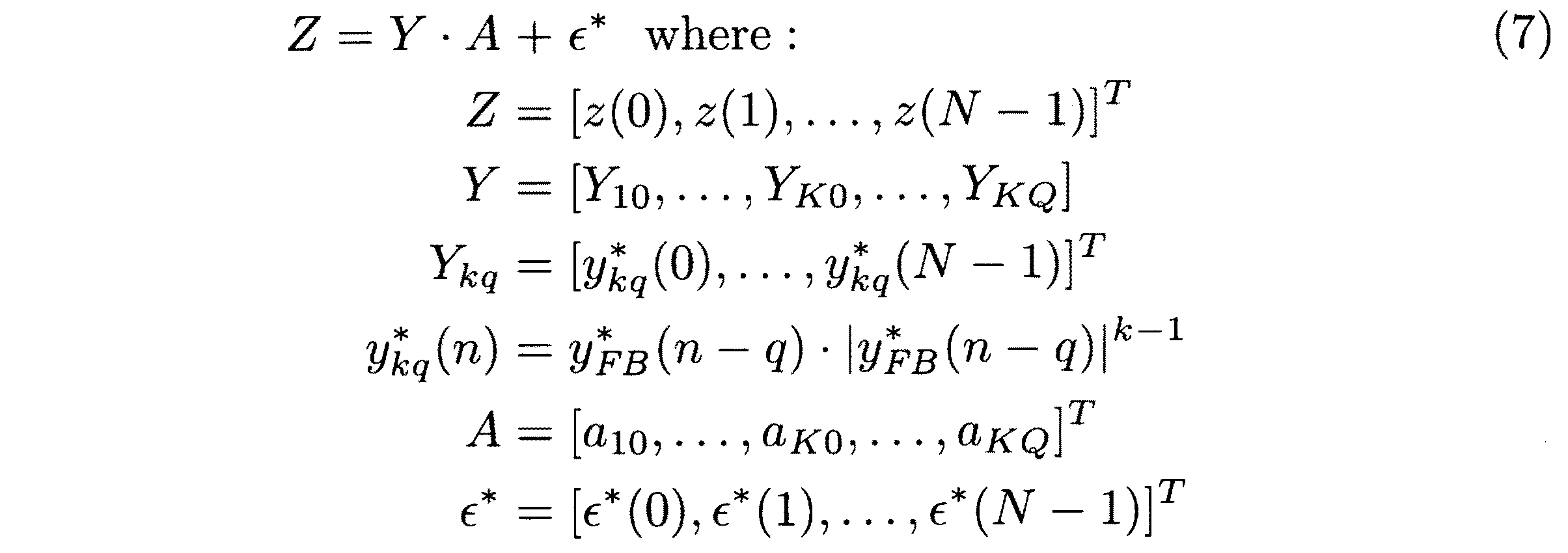
n=0,1,…,N−1を式(6)に代入したものは、式(7)に示すように行列形式でまとめて表現することができる。Zはz(n)を列挙したN行の列ベクトルであり、Aは補償係数を列挙したK×(Q+1)行の列ベクトルであり、ε*はε*(n)を列挙したN行の列ベクトルである。YはN行K×(Q+1)列の行列である。YはK×(Q+1)個の列ベクトルYkqに分解することができ、Ykqはあるk,qについてy* FB(n−q)・|y* FB(n−q)|k-1を列挙したN行の列ベクトルである。なお、最小二乗法によってε*を最小化する場合、Aは式(8)のように解くことができる。 Those obtained by substituting n = 0, 1,..., N−1 into Expression (6) can be collectively expressed in matrix form as shown in Expression (7). Z is a column vector of N rows listing z (n), A is a column vector of K × (Q + 1) rows listing compensation coefficients, and ε * is an N row listing ε * (n). Is a column vector. Y is a matrix of N rows and K × (Q + 1) columns. Y can be decomposed into K × (Q + 1) column vectors Y kq, Y kq is k, the q y * FB (n-q ) · | y * FB (n-q) | k-1 Are N-row column vectors. When ε * is minimized by the method of least squares, A can be solved as shown in Equation (8).
![]()
![]()
次に、複合LPF115,117の信号処理について説明する。
図7は、複合LPFの例を示すブロック図である。
複合LPF115は、LPF131,135、減算器132、包絡線検波器133および加算器134を有する。複合LPF117も複合LPF115と同様の構造を有する。ただし、複合LPF115はy(n)/Gを取得してyFB(n)を出力するのに対し、複合LPF117はy* FB(n)を取得してy^FB(n)を出力する。
Next, signal processing of the composite LPFs 115 and 117 will be described.
FIG. 7 is a block diagram illustrating an example of a composite LPF.
The
LPF131は、減衰器114からフィードバック信号としてy(n)/Gを取得する。すると、LPF131は、フィードバック信号のうち所定の周波数以下の低周波成分を通過させそれ以外の高周波成分をカットすることで、フィードバック信号の帯域幅を制限する。ただし、複合LPF115は、帯域通過フィルタ(BPF:Band Pass Filter)などの他の種類のフィルタを用いて、帯域制限を行ってもよい。
The
減算器132は、LPF131に入力されるフィードバック信号から、LPF131によって帯域幅が制限されたフィードバック信号を引く。これにより、元のフィードバック信号に含まれる高周波成分を抽出することができる。ただし、複合LPF115は、他の方法によってフィードバック信号の高周波成分を抽出してもよい。
The
包絡線検波器133は、減算器132が抽出した高周波数帯の信号を、所定の変換方法に従って、LPF131,135を通過することができる低周波数帯の信号に変換する非線形変換部の一例である。包絡線検波器133は、減算器132が抽出した信号の包絡線を検出し、減算器132が抽出した信号より周波数の低い信号を生成する。
The
包絡線検波器133が取得する高周波数帯の信号と包絡線検波器133が生成する低周波数帯の信号との間には相関がある。すなわち、異なる特徴をもつ高周波数帯の信号は、異なる特徴をもつ低周波数帯の信号に変換される。ただし、複合LPF115は、包絡線検波以外の方法で、高周波数帯の信号を低周波数帯の信号に変換してもよい。例えば、非線形変換部として、各信号の絶対値を算出する絶対値関数を用いることもできる。なお、周波数スペクトルをそのまま高周波数帯から低周波数帯にシフトする周波数シフタと比べて、包絡線検波器や絶対値関数の方が、回路の規模や複雑性を低減できる。
There is a correlation between the high frequency band signal acquired by the
加算器134は、LPF131を通過したフィードバック信号に、包絡線検波器133が生成した信号を合成する。これにより、LPF131によってカットされた高周波成分に応じた特徴が、LPF131,135を通過する低周波成分に付加される。
The
LPF135は、信号合成によって生じた高周波帯への漏洩電力をカットする。LPF135の通過帯域は、LPF131の通過帯域と同一でよい。ただし、信号合成によって生じる漏洩電力が十分に小さい場合は、LPF135を省略してもよい。
The
図8は、複合LPFにおける周波数スペクトルの変化例を示す図である。
ここでは、負の周波数も考慮し、正負対称の周波数スペクトルを記載している。減衰器114が出力する信号s1の周波数スペクトルには、データ通信に用いられる所望の周波数帯域の外に相互変調歪(IMD:Inter Modulation Distortion)が含まれている。複合LPF115を通過する通過帯域は、周波数の絶対値が閾値以下であって、データ通信に用いられる所望の周波数帯域よりも広い周波数帯域に設定されている。ここでは、通過帯域に含まれる相互変調歪を低周波IMDと呼ぶことがあり、複合LPF115によってカットされる遮断帯域に含まれる相互変調歪を高周波IMDと呼ぶことがある。
FIG. 8 is a diagram illustrating a change example of the frequency spectrum in the composite LPF.
Here, in consideration of negative frequencies, a frequency spectrum with positive and negative symmetry is shown. The frequency spectrum of the signal s 1 output from the
複合LPF115は、信号s1から、低周波IMDを含む通過帯域の信号s2と、高周波IMDを含む遮断帯域の信号s3とを抽出する。複合LPF115は、抽出した信号s3を、信号s3の周波数スペクトルと相関のある通過帯域の信号s4に変換する。そして、複合LPF115は、信号s2に信号s4を合成して信号s5を生成する。複合LPF117でも、参照信号に対して複合LPF115と同様の処理が実行される。
The
HPAモデリング部116のモデルが収束する前は、フィードバック信号と参照信号との間に大きな誤差がある。このとき、帯域制限されたフィードバック信号および参照信号には低周波IMDに加えて高周波IMDに応じた特徴も付加されているため、HPAモデリング部116は高周波IMDの違いも考慮してモデルを更新することになる。一方、モデルが収束すると、フィードバック信号と参照信号との間の誤差はゼロに近くなる。このとき、フィードバック信号に付加された高周波IMDに応じた特徴と参照信号に付加された高周波IMDに応じた特徴とが相殺されるため、複合LPF115,117による処理はHPAモデリング部116に影響を与えなくなる。このように、複合LPF115,117を挿入することで、HPAモデリング部116のモデルの精度が向上する。
Before the model of the
次に、DPD112のトレーニングの手順について説明する。
図9は、DPDトレーニングの手順例を示すフローチャートである。
(S1)無線送信装置100は、DPD112へのサンプル信号の入力を開始する。サンプル信号は、例えば、ランダムに生成された1無線フレーム分の信号とする。DPD112は、入力されたサンプル信号それぞれに対して歪補償を行う。電力増幅器113は、歪補償が行われたサンプル信号それぞれを増幅する。減衰器114は、電力増幅器113の出力を所定の減衰率で減衰してフィードバック信号を生成する。
Next, a procedure for training the
FIG. 9 is a flowchart showing an example of the procedure of DPD training.
(S1) The
(S2)第1フェーズとして、HPAモデリング部116は電力増幅器113のモデルを算出する。第1フェーズは、以下のステップS21〜S24の処理を含む。
(S21)複合LPF115は、減衰器114から取得したフィードバック信号の帯域幅を制限する。このとき、複合LPF115は、遮断帯域(高周波帯域)に含まれる高周波IMDに応じた特徴を通過帯域(低周波帯域)の信号に付加する。
(S2) As a first phase, the
(S21) The
(S22)HPAモデリング部116は、DPD112から取得したサンプル信号に対して、HPAモデリング部116が現在保持するモデルを適用して参照信号を生成する。
(S23)複合LPF117は、HPAモデリング部116から取得した参照信号の帯域幅を制限する。このとき、複合LPF117は、遮断帯域(高周波帯域)に含まれる高周波IMDに応じた特徴を通過帯域(低周波帯域)の信号に付加する。
(S22) The
(S23) The
(S24)減算器118は、複合LPF117から帯域幅が制限された参照信号を取得し、複合LPF115から帯域幅が制限されたフィードバック信号を取得する。減算器118は、取得した参照信号と取得したフィードバック信号との間の誤差を示す誤差信号を生成する。以上のフィードバック信号の生成、参照信号の生成および誤差信号の生成は、第1フェーズで使用するサンプル信号の数分(N回)実行される。HPAモデリング部116は、N個の誤差信号および最小二乗平均アルゴリズムなどの統計的手法を用いて、全体の誤差が最小になるように電力増幅器113のモデルを更新する。
(S24) The
(S3)第2フェーズとして、トレーニングDPD121は上記モデルの逆モデルを示す補償係数を算出する。第2フェーズは、以下のステップS31〜S33の処理を含む。
(S31)HPAモデリング部116は、DPD112から取得したサンプル信号に対して、第1フェーズで更新したモデルを適用して理想フィードバック信号を生成する。
(S3) As the second phase, the
(S31) The
(S32)トレーニングDPD121は、HPAモデリング部116から取得した理想フィードバック信号に対して、トレーニングDPD121が現在保持する補償係数(DPD112が現在使用する補償係数と同じもの)を適用して歪補償を行う。
(S32) The
(S33)減算器122は、DPD112から歪補償が行われたサンプル信号を取得し、トレーニングDPD121から歪補償が行われた理想フィードバック信号を取得する。減算器122は、取得したサンプル信号と取得した理想フィードバック信号との間の誤差を示す誤差信号を生成する。以上の理想フィードバック信号の生成や誤差信号の生成は、第2フェーズで使用するサンプル信号の数分(N回)実行される。トレーニングDPD121は、N個の誤差信号および最小二乗法などの統計的手法を用いて、全体の誤差が最小になるようにトレーニングDPD121がもつ補償係数を更新する。
(S33) The
(S4)トレーニングDPD121は、補償係数をDPD112にコピーする。
(S5)無線送信装置100は、トレーニングの終了条件が具備されたか判断する。トレーニングの終了条件としては、例えば、ステップS1〜S4の学習を所定回数繰り返したことなどの回数条件や、減算器122で算出される誤差が閾値以下になったことなどの品質条件が挙げられる。トレーニングの終了条件を具備した場合はDPDトレーニングが終了し、具備していない場合はステップS1に処理が進む。
(S4) The
(S5) The
図10は、帯域フィルタリングの手順例を示すフローチャートである。
この帯域フィルタリングは、上記のステップS21において複合LPF115によって実行され、また、上記のステップS23において複合LPF117によって実行される。以下では、複合LPF115が実行するものとして帯域フィルタリングを説明する。
FIG. 10 is a flowchart illustrating a procedure example of band filtering.
This band filtering is executed by the
(S61)LPF131は、複合LPF115に入力された信号s1(フィードバック信号)から、周波数の絶対値が閾値以下である低周波帯域の信号s2を抽出し、それ以外の高周波帯域の信号をカットする。LPF131を通過する低周波帯域は、データ通信に用いられる所望の周波数帯域よりも広く、抑制されるべき低周波IMDを含んでいる。
(S61) The
(S62)減算器132は、信号s1から信号s2を引くことで、LPF131によってカットされた高周波帯域の信号s3を抽出する。減算器132から出力される高周波帯域の信号s3は、抑制されるべき高周波IMDを含んでいる。
(S62) The
(S63)包絡線検波器133は、高周波帯域の信号s3を、信号s3の周波数スペクトルと相関のある低周波帯域の信号s4に変換する。この高周波数帯域から低周波数帯域への信号変換は非線形変換である。複合LPF115は、包絡線検波器133に代えて、絶対値関数などの他の種類の非線形変換部を備えていてもよい。
(S63)
(S64)加算器134は、信号s3から変換された低周波帯域の信号s4を、LPF131が抽出した信号s2に合成して信号s5を生成する(例えば、信号s2を示す複素数と信号s4を示す複素数とを加算する)。これにより、LPF131によってカットされる高周波IMDの特徴が、複合LPF115を通過する信号s5に反映される。
(S64)
(S65)LPF135は、信号s5から高周波帯域の信号をカットする。LPF135を通過する周波数帯域はLPF131と同じでよい。
図11は、周波数スペクトルの例を示すグラフである。
(S65)
FIG. 11 is a graph showing an example of a frequency spectrum.
この周波数スペクトルのグラフは、電力増幅器113の出力信号のシミュレーション結果を示している。ここでは、フィードバックパスおよびフォワードパスに、LPFも複合LPFも設けなかった場合(LPFなし)、単純なLPFを設けた場合(LPF)、複合LPFを設けた場合(複合LPF)の3通りについてシミュレーションを行っている。
This graph of the frequency spectrum shows the simulation result of the output signal of the
「LPFなし」では、隣接周波数帯域に現れる相互変調歪が3通りの中で最も小さい。しかし、フィードバック信号の帯域幅を制限しないと、ADCなどの信号処理ユニットの負荷や要求される信号処理能力が大きくなってしまう。「LPF」では、フィードバック信号の帯域幅を制限できるものの、隣接周波数帯域に現れる相互変調歪が非常に大きくなっている。これに対し、「複合LPF」では、フィードバック信号の帯域幅を制限しつつ、隣接周波数帯域に現れる相互変調歪を「LPF」の場合よりも抑制できている。 In “no LPF”, the intermodulation distortion appearing in the adjacent frequency band is the smallest among the three types. However, unless the bandwidth of the feedback signal is limited, the load on the signal processing unit such as the ADC and the required signal processing capability will increase. In “LPF”, although the bandwidth of the feedback signal can be limited, the intermodulation distortion appearing in the adjacent frequency band is very large. On the other hand, in the “composite LPF”, the intermodulation distortion appearing in the adjacent frequency band can be suppressed more than in the case of “LPF” while limiting the bandwidth of the feedback signal.
図12は、隣接チャネル漏洩電力比の例を示すグラフである。
この隣接チャネル漏洩電力比(ACLR:Adjacent Channel Leakage Ratio)のグラフは、電力増幅器113の出力信号のシミュレーション結果を示している。ここでは、フィードバックパスおよびフォワードパスに、単純なLPFを設けた場合(LPF)、複合LPFを設けた場合(複合LPF)の2通りについてシミュレーションを行っている。
FIG. 12 is a graph showing an example of adjacent channel leakage power ratio.
This adjacent channel leakage power ratio (ACLR) graph shows the simulation result of the output signal of the
シミュレーション結果によれば、LPFを通過する通過帯域の幅を40MHz以上に広げた場合、「LPF」の場合も「複合LPF」の場合もACLRに差はない。一方、通過帯域の幅を40MHz未満に制限すると、「複合LPF」の場合の方が「LPF」の場合よりもACLRが小さく、通過帯域が狭いほど両者の差が大きくなる。例えば、通過帯域の幅を15MHz程度に制限した場合、「LPF」ではACLRが約−56dBcであるのに対し、「複合LPF」ではACLRが約−58dBcに抑制される。 According to the simulation result, there is no difference in ACLR in both cases of “LPF” and “composite LPF” when the width of the passband passing through the LPF is expanded to 40 MHz or more. On the other hand, when the width of the pass band is limited to less than 40 MHz, the ACLR is smaller in the case of “composite LPF” than in the case of “LPF”, and the difference between the two becomes larger as the pass band is narrower. For example, when the width of the pass band is limited to about 15 MHz, the ACLR in “LPF” is approximately −56 dBc, whereas the ACLR is suppressed to approximately −58 dBc in “composite LPF”.
第2の実施の形態の無線送信装置100によれば、電力増幅器113から減算器118へフィードバックされるフィードバック信号の帯域幅がLPFを用いて制限される。よって、無線送信装置100の負荷を削減でき、また、ADCなどの各種の信号処理ユニットのコストを抑えることができる。また、無線送信装置100によれば、フィードバック信号および参照信号それぞれについて、LPFによってカットされる高周波成分に応じて、LPFを通過する低周波成分が変形される。よって、HPAモデリング部116は、帯域幅が制限されても高周波IMDを考慮して電力増幅器113のモデルを算出することができ、トレーニングDPD121で算出される補償係数の精度を向上させることができる。その結果、電力増幅器113による隣接チャネルへの電力漏洩を削減できる。
According to the
2 電力増幅器
10 歪補償装置
11 プリディストータ
12 帯域制限部
13 学習部
14,15 周波数帯域
2
Claims (5)
前記電力増幅器からフィードバックされるフィードバック信号のうち第1の周波数帯域以外の第2の周波数帯域の成分を制限し、また、制限される前記第2の周波数帯域の成分に応じて前記第1の周波数帯域の成分を変形する帯域制限部と、
前記変形されたフィードバック信号に基づいて前記補償係数を更新する学習部と、
を有する歪補償装置。 A predistorter for applying distortion corresponding to a compensation coefficient to an input signal input to the power amplifier;
Of the feedback signal fed back from the power amplifier, the second frequency band component other than the first frequency band is limited, and the first frequency is determined according to the limited second frequency band component. A band limiter for transforming the band components;
A learning unit that updates the compensation coefficient based on the transformed feedback signal;
A distortion compensation device.
前記学習部は、前記変形されたフィードバック信号と前記変形された参照信号とに基づいて前記補償係数を更新する、請求項1記載の歪補償装置。 The component of the second frequency band in the reference signal corresponding to the feedback signal is limited, and the component of the first frequency band in the reference signal according to the component of the second frequency band to be limited And further having another band limiting unit that transforms
The distortion compensation apparatus according to claim 1, wherein the learning unit updates the compensation coefficient based on the modified feedback signal and the modified reference signal.
前記電力増幅器からフィードバックされるフィードバック信号のうち第1の周波数帯域以外の第2の周波数帯域の成分を制限し、また、制限される前記第2の周波数帯域の成分に応じて前記第1の周波数帯域の成分を変形し、
前記変形されたフィードバック信号に基づいて、前記電力増幅器に入力する入力信号に対して前記プリディストータが使用する補償係数を更新する、
歪補償方法。 A distortion compensation method for compensating for distortion generated in a power amplifier using a predistorter,
Of the feedback signal fed back from the power amplifier, the second frequency band component other than the first frequency band is limited, and the first frequency is determined according to the limited second frequency band component. Transform the band components,
Updating a compensation factor used by the predistorter for an input signal input to the power amplifier based on the transformed feedback signal;
Distortion compensation method.
Priority Applications (2)
| Application Number | Priority Date | Filing Date | Title |
|---|---|---|---|
| JP2014015581A JP2015142325A (en) | 2014-01-30 | 2014-01-30 | Distortion compensation apparatus and distortion compensation method |
| US14/490,200 US9397619B2 (en) | 2014-01-30 | 2014-09-18 | Distortion compensation apparatus and distortion compensation method |
Applications Claiming Priority (1)
| Application Number | Priority Date | Filing Date | Title |
|---|---|---|---|
| JP2014015581A JP2015142325A (en) | 2014-01-30 | 2014-01-30 | Distortion compensation apparatus and distortion compensation method |
Publications (1)
| Publication Number | Publication Date |
|---|---|
| JP2015142325A true JP2015142325A (en) | 2015-08-03 |
Family
ID=53680035
Family Applications (1)
| Application Number | Title | Priority Date | Filing Date |
|---|---|---|---|
| JP2014015581A Pending JP2015142325A (en) | 2014-01-30 | 2014-01-30 | Distortion compensation apparatus and distortion compensation method |
Country Status (2)
| Country | Link |
|---|---|
| US (1) | US9397619B2 (en) |
| JP (1) | JP2015142325A (en) |
Cited By (3)
| Publication number | Priority date | Publication date | Assignee | Title |
|---|---|---|---|---|
| CN107359864A (en) * | 2017-07-25 | 2017-11-17 | 中国工程物理研究院电子工程研究所 | The adaptive agile digital pre-distortion method of frequency agility power amplifier |
| WO2017217222A1 (en) * | 2016-06-16 | 2017-12-21 | 村田機械株式会社 | Positioning control device and mold-clamping apparatus |
| JP2024520937A (en) * | 2021-05-12 | 2024-05-27 | アナログ ディヴァイスィズ インク | Model architecture search and hardware optimization |
Families Citing this family (59)
| Publication number | Priority date | Publication date | Assignee | Title |
|---|---|---|---|---|
| CN103023842B (en) * | 2012-11-26 | 2016-08-24 | 大唐移动通信设备有限公司 | A kind of Multiband pre-distortion factor lookup table update method and system |
| US10231206B2 (en) | 2013-03-15 | 2019-03-12 | DGS Global Systems, Inc. | Systems, methods, and devices for electronic spectrum management for identifying signal-emitting devices |
| US12256233B2 (en) | 2013-03-15 | 2025-03-18 | Digital Global Systems, Inc. | Systems and methods for automated financial settlements for dynamic spectrum sharing |
| US10257727B2 (en) | 2013-03-15 | 2019-04-09 | DGS Global Systems, Inc. | Systems methods, and devices having databases and automated reports for electronic spectrum management |
| US10237770B2 (en) | 2013-03-15 | 2019-03-19 | DGS Global Systems, Inc. | Systems, methods, and devices having databases and automated reports for electronic spectrum management |
| US12356206B2 (en) | 2013-03-15 | 2025-07-08 | Digital Global Systems, Inc. | Systems and methods for automated financial settlements for dynamic spectrum sharing |
| US10244504B2 (en) | 2013-03-15 | 2019-03-26 | DGS Global Systems, Inc. | Systems, methods, and devices for geolocation with deployable large scale arrays |
| US10299149B2 (en) | 2013-03-15 | 2019-05-21 | DGS Global Systems, Inc. | Systems, methods, and devices for electronic spectrum management |
| US10257728B2 (en) | 2013-03-15 | 2019-04-09 | DGS Global Systems, Inc. | Systems, methods, and devices for electronic spectrum management |
| US10219163B2 (en) | 2013-03-15 | 2019-02-26 | DGS Global Systems, Inc. | Systems, methods, and devices for electronic spectrum management |
| US9622041B2 (en) | 2013-03-15 | 2017-04-11 | DGS Global Systems, Inc. | Systems, methods, and devices for electronic spectrum management |
| US11646918B2 (en) | 2013-03-15 | 2023-05-09 | Digital Global Systems, Inc. | Systems, methods, and devices for electronic spectrum management for identifying open space |
| US10257729B2 (en) | 2013-03-15 | 2019-04-09 | DGS Global Systems, Inc. | Systems, methods, and devices having databases for electronic spectrum management |
| US10271233B2 (en) | 2013-03-15 | 2019-04-23 | DGS Global Systems, Inc. | Systems, methods, and devices for automatic signal detection with temporal feature extraction within a spectrum |
| US9484962B1 (en) * | 2015-06-05 | 2016-11-01 | Infineon Technologies Ag | Device and method for adaptive digital pre-distortion |
| US10862529B2 (en) | 2015-08-18 | 2020-12-08 | Wilson Electronics, Llc | Separate uplink and downlink antenna repeater architecture |
| US10673517B2 (en) | 2016-11-15 | 2020-06-02 | Wilson Electronics, Llc | Desktop signal booster |
| CA3043878A1 (en) | 2016-11-15 | 2018-05-24 | Wilson Electronics, Llc | Desktop signal booster |
| US12183213B1 (en) | 2017-01-23 | 2024-12-31 | Digital Global Systems, Inc. | Unmanned vehicle recognition and threat management |
| US10529241B2 (en) | 2017-01-23 | 2020-01-07 | Digital Global Systems, Inc. | Unmanned vehicle recognition and threat management |
| US12205477B2 (en) | 2017-01-23 | 2025-01-21 | Digital Global Systems, Inc. | Unmanned vehicle recognition and threat management |
| US10459020B2 (en) | 2017-01-23 | 2019-10-29 | DGS Global Systems, Inc. | Systems, methods, and devices for automatic signal detection based on power distribution by frequency over time within a spectrum |
| US10700794B2 (en) | 2017-01-23 | 2020-06-30 | Digital Global Systems, Inc. | Systems, methods, and devices for automatic signal detection based on power distribution by frequency over time within an electromagnetic spectrum |
| US10498951B2 (en) | 2017-01-23 | 2019-12-03 | Digital Global Systems, Inc. | Systems, methods, and devices for unmanned vehicle detection |
| US10581469B1 (en) * | 2017-04-17 | 2020-03-03 | DeepSig Inc. | Machine learning-based nonlinear pre-distortion system |
| US10943461B2 (en) | 2018-08-24 | 2021-03-09 | Digital Global Systems, Inc. | Systems, methods, and devices for automatic signal detection based on power distribution by frequency over time |
| US11133834B2 (en) | 2019-03-07 | 2021-09-28 | Samsung Electronics Co., Ltd. | Device and method of compensating for nonlinearity of power amplifier |
| US11424767B2 (en) * | 2020-01-14 | 2022-08-23 | The Regents Of The University Of Colorado, A Body Corporate | Out-of-band compensation of active electronic device |
| US12302113B2 (en) | 2020-05-01 | 2025-05-13 | Digital Global Systems, Inc. | System, method, and apparatus for providing dynamic, prioritized spectrum management and utilization |
| US12177679B2 (en) | 2020-05-01 | 2024-12-24 | Digital Global Systems, Inc. | System, method, and apparatus for providing dynamic, prioritized spectrum management and utilization |
| US11395149B2 (en) | 2020-05-01 | 2022-07-19 | Digital Global Systems, Inc. | System, method, and apparatus for providing dynamic, prioritized spectrum management and utilization |
| US12294866B2 (en) | 2020-05-01 | 2025-05-06 | Digital Global Systems, Inc. | System, method, and apparatus for providing dynamic, prioritized spectrum management and utilization |
| US12212974B2 (en) | 2020-05-01 | 2025-01-28 | Digital Global Systems, Inc. | System, method, and apparatus for providing dynamic, prioritized spectrum management and utilization |
| US11638160B2 (en) | 2020-05-01 | 2023-04-25 | Digital Global Systems, Inc. | System, method, and apparatus for providing dynamic, prioritized spectrum management and utilization |
| US12219365B2 (en) | 2020-05-01 | 2025-02-04 | Digital Global Systems, Inc. | System, method, and apparatus for providing dynamic, prioritized spectrum management and utilization |
| US12413984B2 (en) | 2020-05-01 | 2025-09-09 | Digital Global Systems, Inc. | System, method, and apparatus for providing dynamic, prioritized spectrum management and utilization |
| US12262213B2 (en) | 2020-05-01 | 2025-03-25 | Digital Global Systems, Inc. | System, method, and apparatus for providing dynamic, prioritized spectrum management and utilization |
| US12256225B2 (en) | 2020-05-01 | 2025-03-18 | Digital Global Systems, Inc. | System, method, and apparatus for providing dynamic, prioritized spectrum management and utilization |
| US12262211B2 (en) | 2020-05-01 | 2025-03-25 | Digital Global Systems, Inc. | System, method, and apparatus for providing dynamic, prioritized spectrum management and utilization |
| US12323812B2 (en) | 2020-05-01 | 2025-06-03 | Digital Global Systems, Inc. | System, method, and apparatus for providing dynamic, prioritized spectrum management and utilization |
| US12192777B2 (en) | 2020-05-01 | 2025-01-07 | Digital Global Systems, Inc. | System, method, and apparatus for providing dynamic, prioritized spectrum management and utilization |
| US11653213B2 (en) | 2020-05-01 | 2023-05-16 | Digital Global Systems. Inc. | System, method, and apparatus for providing dynamic, prioritized spectrum management and utilization |
| US11665547B2 (en) | 2020-05-01 | 2023-05-30 | Digital Global Systems, Inc. | System, method, and apparatus for providing dynamic, prioritized spectrum management and utilization |
| US11700533B2 (en) | 2020-05-01 | 2023-07-11 | Digital Global Systems, Inc. | System, method, and apparatus for providing dynamic, prioritized spectrum management and utilization |
| US12096230B2 (en) | 2020-05-01 | 2024-09-17 | Digital Global Systems, Inc. | System, method, and apparatus for providing dynamic, prioritized spectrum management and utilization |
| US11849332B2 (en) | 2020-05-01 | 2023-12-19 | Digital Global Systems, Inc. | System, method, and apparatus for providing dynamic, prioritized spectrum management and utilization |
| US12133082B2 (en) | 2020-05-01 | 2024-10-29 | Digital Global Systems, Inc. | System, method, and apparatus for providing dynamic, prioritized spectrum management and utilization |
| US12309599B2 (en) | 2020-05-01 | 2025-05-20 | Digital Global Systems, Inc. | System, method, and apparatus for providing dynamic, prioritized spectrum management and utilization |
| US12513528B2 (en) | 2020-05-01 | 2025-12-30 | Digital Global Systems, Inc. | System, method, and apparatus for providing dynamic, prioritized spectrum management and utilization |
| US12324037B1 (en) * | 2020-11-04 | 2025-06-03 | Sprint Spectrum Lp | Ensuring quality of service for relay nodes |
| US11751064B1 (en) | 2022-08-02 | 2023-09-05 | Digital Global Systems, Inc. | System, method, and apparatus for providing optimized network resources |
| US12294865B2 (en) | 2022-08-02 | 2025-05-06 | Digital Global Systems, Inc. | System, method, and apparatus for providing optimized network resources |
| US11843953B1 (en) | 2022-08-02 | 2023-12-12 | Digital Global Systems, Inc. | System, method, and apparatus for providing optimized network resources |
| US12483898B2 (en) | 2022-08-02 | 2025-11-25 | Digital Global Systems, Inc. | System, method, and apparatus for providing optimized network resources |
| US12156037B2 (en) | 2022-08-02 | 2024-11-26 | Digital Global Systems, Inc. | System, method, and apparatus for providing optimized network resources |
| US12250558B2 (en) | 2022-08-02 | 2025-03-11 | Digital Global Systems, Inc. | System, method, and apparatus for providing optimized network resources |
| US11570627B1 (en) | 2022-08-02 | 2023-01-31 | Digital Global Systems, Inc. | System, method, and apparatus for providing optimized network resources |
| US11659400B1 (en) | 2022-08-02 | 2023-05-23 | Digital Global Systems, Inc. | System, method, and apparatus for providing optimized network resources |
| US12262212B2 (en) | 2022-08-02 | 2025-03-25 | Digital Global Systems, Inc. | System, method, and apparatus for providing optimized network resources |
Family Cites Families (9)
| Publication number | Priority date | Publication date | Assignee | Title |
|---|---|---|---|---|
| US7409007B1 (en) | 1999-09-14 | 2008-08-05 | Lucent Technologies Inc. | Method and apparatus for reducing adjacent channel power in wireless communication systems |
| JP2002290166A (en) | 2001-03-28 | 2002-10-04 | Hitachi Kokusai Electric Inc | Amplifier |
| JP4071526B2 (en) * | 2002-04-10 | 2008-04-02 | 松下電器産業株式会社 | Nonlinear distortion compensation apparatus and transmission apparatus |
| JP4342425B2 (en) | 2004-11-12 | 2009-10-14 | 富士通株式会社 | Wireless communication device |
| CN100576724C (en) | 2005-05-18 | 2009-12-30 | 株式会社Ntt都科摩 | Power Series Type Predistorter and Its Control Method |
| JP2009111958A (en) * | 2007-11-01 | 2009-05-21 | Hitachi Kokusai Electric Inc | Predistorter |
| JP5205182B2 (en) * | 2008-09-09 | 2013-06-05 | 株式会社日立国際電気 | Distortion compensation amplifier |
| JP5834804B2 (en) | 2011-11-16 | 2015-12-24 | 富士通株式会社 | Adaptive linearizer with narrowband feedback path. |
| JP5958324B2 (en) * | 2012-12-19 | 2016-07-27 | 富士通株式会社 | Distortion compensation apparatus and distortion compensation method for power amplification apparatus |
-
2014
- 2014-01-30 JP JP2014015581A patent/JP2015142325A/en active Pending
- 2014-09-18 US US14/490,200 patent/US9397619B2/en not_active Expired - Fee Related
Cited By (6)
| Publication number | Priority date | Publication date | Assignee | Title |
|---|---|---|---|---|
| WO2017217222A1 (en) * | 2016-06-16 | 2017-12-21 | 村田機械株式会社 | Positioning control device and mold-clamping apparatus |
| JPWO2017217222A1 (en) * | 2016-06-16 | 2019-02-14 | 村田機械株式会社 | Positioning control device and mold clamping device |
| US10935956B2 (en) | 2016-06-16 | 2021-03-02 | Murata Machinery, Ltd. | Positioning control device and mold-clamping apparatus |
| CN107359864A (en) * | 2017-07-25 | 2017-11-17 | 中国工程物理研究院电子工程研究所 | The adaptive agile digital pre-distortion method of frequency agility power amplifier |
| CN107359864B (en) * | 2017-07-25 | 2020-08-21 | 中国工程物理研究院电子工程研究所 | Self-adaptive agile digital predistortion method for frequency agile power amplifier |
| JP2024520937A (en) * | 2021-05-12 | 2024-05-27 | アナログ ディヴァイスィズ インク | Model architecture search and hardware optimization |
Also Published As
| Publication number | Publication date |
|---|---|
| US9397619B2 (en) | 2016-07-19 |
| US20150214904A1 (en) | 2015-07-30 |
Similar Documents
| Publication | Publication Date | Title |
|---|---|---|
| JP2015142325A (en) | Distortion compensation apparatus and distortion compensation method | |
| CN101911477B (en) | Predistorter | |
| JP5637065B2 (en) | Amplifier circuit and wireless communication device | |
| JP5071370B2 (en) | Distortion compensation apparatus and method | |
| EP1560329A1 (en) | Digital predistorter using power series model | |
| US8903015B2 (en) | Apparatus and method for digital predistortion of non-linear amplifiers | |
| US20120126898A1 (en) | Amplifying apparatus | |
| JP5664116B2 (en) | Power amplification apparatus, distortion compensation coefficient updating method thereof, and transmission apparatus | |
| JP2009111958A (en) | Predistorter | |
| Le Duc et al. | An adaptive cascaded ILA-and DLA-based digital predistorter for linearizing an RF power amplifier | |
| KR101386239B1 (en) | Predistorter for compensating of nonlinear distortion and method for the same | |
| US20120154041A1 (en) | Predistortion apparatuses and methods | |
| US9276533B2 (en) | Distortion compensation apparatus and method | |
| US9444412B2 (en) | Distortion compensation apparatus and method therefor | |
| JP2005117613A (en) | Digital feedback linearizing apparatus and method for linearizing power amplifier | |
| US8804872B1 (en) | Dynamic determination of volterra kernels for digital pre-distortion | |
| US8712345B2 (en) | Distortion compensation device, distortion compensation method, and radio transmitter | |
| US9712121B2 (en) | Circuits for linearizing an output signal of a non-linear component and related devices and methods | |
| CN101765187B (en) | A digital predistortion method and system | |
| Tikhonov et al. | Correction of non-linear signal distortion on the equipment NI USRP-2943R with OFDM transmission technology | |
| JP6182973B2 (en) | Signal amplification device, distortion compensation method, and wireless transmission device | |
| US9628305B2 (en) | Systems and methods to compensate for memory effects using enhanced memory polynomials | |
| JP2014116691A (en) | High frequency amplification device and distortion compensation method | |
| KR20120054369A (en) | Predistorter using memory polynomial model, predistorting method thereof, and system including the predistorter | |
| Harmon et al. | Iterative approach to the indirect learning architecture for baseband digital predistortion |
Legal Events
| Date | Code | Title | Description |
|---|---|---|---|
| A621 | Written request for application examination |
Free format text: JAPANESE INTERMEDIATE CODE: A621 Effective date: 20161004 |
|
| A977 | Report on retrieval |
Free format text: JAPANESE INTERMEDIATE CODE: A971007 Effective date: 20170929 |
|
| A131 | Notification of reasons for refusal |
Free format text: JAPANESE INTERMEDIATE CODE: A131 Effective date: 20171107 |
|
| A02 | Decision of refusal |
Free format text: JAPANESE INTERMEDIATE CODE: A02 Effective date: 20180501 |