JP2015125601A - Step presentation device, method and program - Google Patents
Step presentation device, method and program Download PDFInfo
- Publication number
- JP2015125601A JP2015125601A JP2013269712A JP2013269712A JP2015125601A JP 2015125601 A JP2015125601 A JP 2015125601A JP 2013269712 A JP2013269712 A JP 2013269712A JP 2013269712 A JP2013269712 A JP 2013269712A JP 2015125601 A JP2015125601 A JP 2015125601A
- Authority
- JP
- Japan
- Prior art keywords
- work
- worker
- search
- unit
- knowledge
- Prior art date
- Legal status (The legal status is an assumption and is not a legal conclusion. Google has not performed a legal analysis and makes no representation as to the accuracy of the status listed.)
- Pending
Links
Images


Landscapes
- Management, Administration, Business Operations System, And Electronic Commerce (AREA)
Abstract
Description
本発明は、工程提示装置、工程提示方法および工程提示プログラムに関する。 The present invention relates to a process presentation device, a process presentation method, and a process presentation program.
従来から、それぞれ知識を有する複数の知識作業者がチームを組んで顧客からの要望に応える業務が存在する。この場合、顧客から直接依頼を受けた知識作業者が主担当者となり、主担当者が一緒に仕事を行う他の知識作業者を選定する。例えば、行政書士は、顧客から相続に関する申請の依頼を受けた場合、主担当者となって、税理士、弁護士、司法書士の3人を他メンバーとして選定し、4人のチームを組んで依頼された業務の各種の作業を遂行する。 Conventionally, there are operations in which a plurality of knowledge workers each having knowledge form a team and respond to customer requests. In this case, the knowledge worker who receives the request directly from the customer becomes the main person in charge, and the other person in charge who works together with the main person in charge is selected. For example, when an administrative scrivener receives a request for an inheritance application from a customer, it becomes the main person in charge and selects three members, a tax accountant, a lawyer, and a judicial scrivener, as members of a team of four. Perform various tasks in the business.
しかしながら、主担当者は、依頼された業務の各種の作業をメンバーの知識作業者に効率よく割り振ることができない場合がある。例えば、主担当者が未経験の業務を顧客から依頼された場合や、主担当者が複数の知識作業者で業務を分担した経験が乏しい場合、作業を効率よく割り振ることができない場合がある。 However, the main person in charge may not be able to efficiently allocate the various tasks of the requested work to the member knowledge workers. For example, when the main person in charge is requested by a customer for inexperienced work, or when the main person in charge has poor experience of sharing work among a plurality of knowledge workers, work may not be efficiently allocated.
なお、このような問題は、行政書士や、税理士、弁護士、司法書士などの複数の知識作業者がチームを組んで業務を遂行する場合に限ったものではなく、例えば、複数の作業者がチームを組んで業務を遂行する場合、全般に該当する問題である。 Such problems are not limited to cases where multiple knowledge workers such as administrative scriveners, tax accountants, lawyers, and judicial scriveners form a team to carry out their work. It is a problem that falls under the general rule when carrying out business with a group.
一側面では、効率のよい作業の割り振りを支援できる工程提示装置、工程提示方法および工程提示プログラムを提供することを目的とする。 An object of one aspect is to provide a process presentation device, a process presentation method, and a process presentation program that can support efficient work allocation.
本発明の一側面によれば、工程提示装置は、記憶部と、受付部と、検索部と、提示部とを有する。記憶部は、複数の作業者により作業を分担して成果物を生成した際に各作業者により実施された作業の工程を示す工程情報を記憶する。受付部は、工程を検索する対象の成果物の指定を受け付ける。検索部は、前記受付部により指定された成果物を生成する際に各作業者により実施された作業の工程を前記工程情報から検索する。提示部は、前記検索部により検索された各作業者の作業の工程を提示する。 According to one aspect of the present invention, the process presentation device includes a storage unit, a reception unit, a search unit, and a presentation unit. A memory | storage part memorize | stores the process information which shows the process of the work implemented by each worker, when a work was shared by several workers and the output was produced | generated. The accepting unit accepts designation of a product to be searched for a process. A search part searches the process of the work implemented by each worker from the said process information when producing | generating the deliverable designated by the said reception part. The presenting unit presents a work process of each worker searched by the search unit.
本発明の一側面によれば、作業を効率よく割り振ることを支援できる。 According to one aspect of the present invention, it is possible to support efficient allocation of work.
以下に、本発明にかかる工程提示装置、工程提示方法および工程提示プログラムの実施例を図面に基づいて詳細に説明する。なお、この実施例によりこの発明が限定されるものではない。そして、各実施例は、処理内容を矛盾させない範囲で適宜組み合わせることが可能である。 Hereinafter, embodiments of a process presentation device, a process presentation method, and a process presentation program according to the present invention will be described in detail based on the drawings. Note that the present invention is not limited to the embodiments. Each embodiment can be appropriately combined within a range in which processing contents are not contradictory.
[システムの構成]
実施例1に係るシステムについて説明する。図1は、工程提示装置を含んだシステムの全体の概略構成の一例を示す図である。図1に示すように、システム11は、工程提示装置10と、クライアント12とを有する。工程提示装置10とクライアント12は、各種の情報を交換することが可能とされている。例えば、工程提示装置10とクライアント12は、ネットワーク13を介して通信可能に接続され、各種の情報を交換することが可能とされている。かかるネットワーク13の一態様としては、有線または無線を問わず、LAN(Local Area Network)やVPN(Virtual Private Network)などの任意の通信網が挙げられる。なお、図1の例では、システム11は、クライアント12を1つ有する場合を例示したが、開示のシステムはこれに限定されず、クライアント12を任意の数とすることができる。
[System configuration]
A system according to the first embodiment will be described. FIG. 1 is a diagram illustrating an example of a schematic configuration of the entire system including a process presentation device. As illustrated in FIG. 1, the
クライアント12は、顧客から依頼された業務に関する各種の作業を行う作業者が用いるコンピュータである。クライアント12は、例えば、デスクトップ型PC(パーソナル・コンピュータ)、タブレット型PC、ノート型PCなどの情報処理装置等である。作業者は、それぞれ所定の知識を有し、知識を利用した作業を行う。なお、以下では、作業者を、それぞれ専門的な知識を有し、当該専門的な知識に関する資格を有する知識作業者とした場合を例に説明する。このような知識作業者としては、例えば、行政書士、税理士、弁護士、司法書士、公認会計士、弁理士などが挙げられる。なお、知識作業者は、これらに限定されるものではない。知識作業者は、専門的な知識を用いて、専門的な分野に関する各種の作業を行う。また、顧客から依頼された業務に応じて、複数の知識作業者がチームを組んで依頼された業務を行う場合がある。この場合、顧客から直接依頼を受けた知識作業者が主担当者となり、主担当者が一緒に仕事を行う他の知識作業者を選定する。例えば、行政書士は、顧客から相続に関する申請の依頼を受けた場合、主担当者となって、他メンバーを選定し、他メンバーとチームを組んで依頼された業務の各種の作業を遂行する。
The
工程提示装置10は、各知識作業者が有する知識を繋いで、依頼者から依頼された要望の解決を支援するサービスを提供するシステムが動作する装置である。工程提示装置10は、例えば、サーバコンピュータなどのコンピュータなどである。工程提示装置10は、1台のコンピュータとして実装してもよく、また、複数台のコンピュータによるクラウドとして実装することもできる。なお、本実施例では、工程提示装置10を1台のコンピュータとした場合を例として説明する。工程提示装置10は、クライアント12からアクセス可能とされている。知識作業者は、クライアント12を用いて工程提示装置10にアクセスし、工程提示装置10により、依頼された業務に関する各種の管理を行う。
The
[工程提示装置の構成]
次に、実施例1に係る工程提示装置10について説明する。図2は、工程提示装置の機能的な構成の一例を示す図である。図2に示すように、工程提示装置10は、通信I/F(インタフェース)部20と、記憶部21と、制御部22とを有する。
[Configuration of process presentation device]
Next, the
通信I/F部20は、他の装置との間で通信制御を行うインタフェースである。通信I/F部20は、ネットワーク13を介して他の装置と各種情報を送受信する。例えば、通信I/F部20は、知識作業者が有するクライアント12へ各種の画面の情報を送信する。また、通信I/F部20は、知識作業者が有するクライアント12から各種の画面に対する入力結果の情報を受信する。かかる通信I/F部20の一態様としては、LANカードなどのネットワークインタフェースカードを採用できる。
The communication I /
記憶部21は、ハードディスク、SSD(Solid State Drive)、光ディスクなどの記憶装置である。なお、記憶部21は、RAM(Random Access Memory)、フラッシュメモリ、NVSRAM(Non Volatile Static Random Access Memory)などのデータを書き換え可能な半導体メモリであってもよい。
The
記憶部21は、制御部22で実行されるOS(Operating System)や各種プログラムを記憶する。さらに、記憶部21は、制御部22で実行されるプログラムで用いられる各種データを記憶する。例えば、記憶部21は、作業者テーブル30と、顧客情報テーブル31と、作業者プロフィールテーブル32と、仕事分野テーブル33と、業務情報テーブル34と、作業工程テーブル35とを有する。
The
作業者テーブル30は、作業者に関する各種の情報を記憶したテーブルである。例えば、作業者テーブル30には、作業者毎に、所持する資格が記憶されている。 The worker table 30 is a table that stores various types of information related to workers. For example, the worker table 30 stores the qualifications possessed for each worker.
図3は、作業者テーブルのデータ構成の一例を示す図である。図3に示すように、作業者テーブル30は、「知識作業者ID」、「所持資格1」、「所持資格2」の各項目を有する。知識作業者ID(identification)の項目は、知識作業者を識別する識別情報を記憶する領域である。各知識作業者には、数字や文字などを組み合わせて、それぞれを識別する識別情報が付与される。知識作業者IDの項目には、知識作業者に付与された知識作業者IDが格納される。所持資格1および所持資格2の項目は、知識作業者が所持する資格を記憶する領域である。知識作業者は、複数の資格を所持する場合がある。このため、本実施例では、作業者テーブル30に資格を記憶する領域を2つ設けているが、資格を記憶する領域を1または3つ以上設けてもよい。
FIG. 3 is a diagram illustrating an example of the data configuration of the worker table. As shown in FIG. 3, the worker table 30 has items of “knowledge worker ID”, “
図3の例では、知識作業者IDが「A1」の知識作業者は、行政書士の資格を有することを示す。 In the example of FIG. 3, the knowledge worker whose knowledge worker ID is “A1” has the qualification of administrative scrivener.
図2に戻り、顧客情報テーブル31は、業務を依頼する依頼者に関する各種の情報を記憶したテーブルである。例えば、顧客情報テーブル31には、依頼者の氏名や連絡先などの情報が格納される。 Returning to FIG. 2, the customer information table 31 is a table that stores various types of information related to the requester who requests the business. For example, the customer information table 31 stores information such as the requester's name and contact information.
図4は、顧客情報テーブルのデータ構成の一例を示す図である。図4に示すように、顧客情報テーブル31は、「顧客ID」、「顧客名」、「連絡先」の各項目を有する。顧客IDの項目は、依頼者を識別する識別情報を記憶する領域である。各依頼者には、それぞれを識別する識別情報が付与される。顧客IDの項目には、依頼者に付与された顧客IDが格納される。顧客名の項目は、依頼者の氏名などの名称を記憶する領域である。連絡先の項目は、依頼者の住所や電話番号、メールなど、依頼者と連絡を取る際の連絡先を記憶する領域である。 FIG. 4 is a diagram illustrating an example of a data configuration of the customer information table. As shown in FIG. 4, the customer information table 31 has items of “customer ID”, “customer name”, and “contact”. The item of customer ID is an area for storing identification information for identifying the client. Each requester is given identification information for identifying each client. The customer ID assigned to the client is stored in the item of customer ID. The item of customer name is an area for storing a name such as the name of the client. The item of contact address is an area for storing a contact address when contacting the client, such as the client's address, telephone number, and mail.
図4の例では、顧客ID「X1」の依頼者は、顧客名が「XX」であり、連絡先が「xxxx−xx−xxxx」であることを示す。 In the example of FIG. 4, the requester of the customer ID “X1” indicates that the customer name is “XX” and the contact information is “xxxx-xxx-xxxx”.
図2に戻り、作業者プロフィールテーブル32は、知識作業者のプロフィールに関する各種の情報が記憶されるテーブルである。例えば、作業者プロフィールテーブル32には、知識作業者の氏名や連絡先などの情報が格納される。なお、本実施例では、作業者テーブル30と作業者プロフィールテーブル32は、1つのテーブルとして構成してもよい。 Returning to FIG. 2, the worker profile table 32 is a table in which various information related to the profile of the knowledge worker is stored. For example, the worker profile table 32 stores information such as the name and contact information of knowledge workers. In the present embodiment, the worker table 30 and the worker profile table 32 may be configured as one table.
図5は、作業者プロフィールテーブルのデータ構成の一例を示す図である。図5に示すように、作業者プロフィールテーブル32は、「知識作業者ID」、「氏名」、「連絡先」の各項目を有する。知識作業者IDの項目は、知識作業者を識別する識別情報として知識作業者IDを記憶する領域である。氏名の項目は、知識作業者の氏名を記憶する領域である。連絡先の項目は、知識作業者の住所や電話番号、メールなど、知識作業者と連絡を取る際の連絡先を記憶する領域である。 FIG. 5 is a diagram illustrating an example of a data configuration of the worker profile table. As shown in FIG. 5, the worker profile table 32 has items of “knowledge worker ID”, “name”, and “contact”. The knowledge worker ID item is an area for storing a knowledge worker ID as identification information for identifying the knowledge worker. The name item is an area for storing the name of the knowledge worker. The item of the contact address is an area for storing a contact address for contacting the knowledge worker, such as the knowledge worker's address, telephone number, and mail.
図5の例では、知識作業者ID「A1」の知識作業者は、氏名が「AA」であり、連絡先が「xxxx−xx−xxxx」であることを示す。 In the example of FIG. 5, the knowledge worker with the knowledge worker ID “A1” indicates that the name is “AA” and the contact is “xxxx-xxx-xxxx”.
図2に戻り、仕事分野テーブル33は、知識作業者が担当可能な業務の分野に関する情報を記憶したテーブルである。例えば、顧客情報テーブル31には、知識作業者が得意とする業務の分野が格納される。 Returning to FIG. 2, the work field table 33 is a table that stores information on fields of work that can be handled by knowledge workers. For example, the customer information table 31 stores business fields that the knowledge worker is good at.
図6は、仕事分野テーブルのデータ構成の一例を示す図である。図6に示すように、仕事分野テーブル33は、「知識作業者ID」、「タグ1」、「タグ2」、「タグ3」の各項目を有する。知識作業者IDの項目は、知識作業者を識別する識別情報として知識作業者IDを記憶する領域である。タグ1、タグ2およびタグ3の各項目は、知識作業者IDの項目に知識作業者IDが格納された知識作業者が担当可能な業務の分野を格納する領域である。知識作業者は、担当可能な業務の分野が複数ある場合がある。このため、本実施例では、仕事分野テーブル33に担当可能な業務の分野を記憶する領域を3つ設けているが、担当可能な業務の分野を記憶する領域を1、2または4つ以上設けてもよい。
FIG. 6 is a diagram illustrating an example of a data configuration of the work field table. As illustrated in FIG. 6, the work field table 33 includes items of “knowledge worker ID”, “
図6の例では、知識作業者ID「A1」の知識作業者は、「相続」、「企業法務」が担当可能な業務の分野であることを示す。 In the example of FIG. 6, the knowledge worker with the knowledge worker ID “A1” indicates that “inheritance” and “corporate legal” are fields of work that can be handled.
図2に戻り、業務情報テーブル34は、依頼された業務に関する各種の情報を記憶したテーブルである。例えば、業務情報テーブル34には、業務を依頼した依頼主に関する情報や、依頼された業務に関する情報、業務を担当する知識作業者に関する情報などの情報が格納される。なお、本実施例では、業務情報テーブル34に、依頼を受けて作業中の業務および遂行済みの業務の情報を共に記憶させている。 Returning to FIG. 2, the business information table 34 is a table that stores various types of information related to the requested business. For example, the business information table 34 stores information on the client who requested the business, information on the requested business, and information on the knowledge worker in charge of the business. In the present embodiment, the business information table 34 stores both information on the business being worked on and the business that has been performed upon receipt of the request.
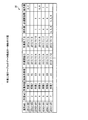
図7は、業務情報テーブルのデータ構成の一例を示す図である。図7に示すように、業務情報テーブル34は、「案件NO」、「相談分野」、「顧客ID」、「顧客依頼日」、「仕事検収日」、「成果物」、「コスト」の各項目を有する。また、業務情報テーブル34は、「メンバー1」、「メンバー1役割」、「メンバー2」、「メンバー2役割」、「メンバー3」、「メンバー3役割」、「メンバー4」、「メンバー4役割」の各項目を有する。案件NOの項目は、依頼された業務を識別する識別情報を記憶する領域である。依頼された各業務には、それぞれを識別する識別情報として案件NOが付与される。案件NOの項目には、依頼された業務に付与された案件NOが格納される。相談分野の項目は、依頼された業務の分野を記憶する領域である。顧客IDの項目は、業務を依頼した依頼主の顧客IDを記憶する領域である。顧客依頼日の項目は、業務が依頼された日付を記憶する領域である。仕事検収日の項目は、依頼された業務に関する検収が行われた日付を記憶する領域である。この仕事検収日の項目に日付が格納された業務は、遂行済みの業務である。成果物の項目は、依頼された業務についての成果物に関する情報を記憶する領域である。コストの項目は、依頼された業務でかかった費用に関する情報を記憶する領域である。メンバー1、メンバー2、メンバー3およびメンバー4の各項目は、業務を担当するメンバーとなる知識作業者の知識作業者IDを記憶する領域である。メンバー1の項目には、主担当者となる知識作業者の知識作業者IDが格納される。メンバー1役割、メンバー2役割、メンバー3役割およびメンバー4役割の各項目は、それぞれの知識作業者が担当する役割を記憶する領域である。知識作業者は、複数の資格を所持する場合がある。このため、知識作業者が業務において、どの資格の作業を行うかを、役割として記憶させるものとしている。本実施例では、業務情報テーブル34に、業務を担当するメンバーに関する領域を4つ設けているが、当可能な業務の分野を記憶する領域を2、3、または5つ以上設けてもよい。
FIG. 7 is a diagram illustrating an example of a data configuration of the business information table. As shown in FIG. 7, the business information table 34 includes “case No.”, “consultation field”, “customer ID”, “customer request date”, “work acceptance date”, “delivery product”, and “cost”. Have items. The business information table 34 includes “
図7の例では、案件NO「i2013−001」の業務は、相談分野が「相続相談」であり、顧客IDが「X1」であり、顧客依頼日が「2013/11/1」であり、仕事検収日が「2013/11/19」であり、成果物が「成果物1」であることを示す。また、案件NO「i2013−001」の業務は、業務でかかった費用が「XXX」円であり、仕事検収日が格納されていることから遂行済みの業務であり、メンバー1に記憶された知識作業者ID「A1」の知識作業者が主担当であることを示す。また、案件NO「i2013−001」の業務は、知識作業者ID「B1」、「C1」の知識作業者が他のメンバーとして案件を担当したことを示す。また、案件NO「i2013−001」の業務は、知識作業者ID「A1」の知識作業者の役割が「行政書士」であり、知識作業者ID「B1」の知識作業者の役割が「税理士」であることを示す。また、案件NO「i2013−001」の業務は、知識作業者ID「C1」の知識作業者の役割が「司法書士」であることを示す。
In the example of FIG. 7, the work of the case number “i2013-001” is that the consultation field is “inheritance consultation”, the customer ID is “X1”, the customer request date is “2013/11/1”, The job acceptance date is “2013/11/19”, and the deliverable is “deliverable 1”. In addition, the work of the case No. “i2013-001” is a work that has been completed because the work cost is “XXX” yen and the work acceptance date is stored, and the knowledge work stored in the
図2に戻り、作業工程テーブル35は、業務で実施された作業に関する各種の情報を記憶したテーブルである。例えば、作業工程テーブル35には、各作業を実施した工程や期間などの作業に関する情報や、各作業の知識作業者への割り当て状況などの情報が格納される。 Returning to FIG. 2, the work process table 35 is a table that stores various types of information related to work performed in business. For example, the work process table 35 stores information related to work such as a process and a period in which each work is performed, and information such as an assignment status of each work to a knowledge worker.
図8は、作業工程テーブルのデータ構成の一例を示す図である。図8に示すように、作業工程テーブル35は、「案件NO」、「作業NO」、「作業内容」、「担当作業者」、「作業開始日」、「作業終了日」、「前作業」、「必須前作業」、「後作業」の各項目を有する。案件NOの項目は、依頼された業務を識別する識別情報として案件NOを記憶する領域である。作業NOの項目は、依頼された業務の各作業を識別する識別情報を記憶する領域である。業務の各作業には、業務毎に、識別情報として1から順にユニークな作業NOが付与される。作業NOの項目には、作業に付与された作業NOが格納される。作業内容の項目は、作業内容に関する情報を記憶する領域である。担当作業者の項目は、作業を担当する知識作業者の知識作業者IDを記憶する領域である。作業開始日の項目は、作業を開始した日付を記憶する領域である。作業終了日の項目は、作業を終了した日付を記憶する領域である。前作業の項目は、前に実施される作業の作業NOを記憶する領域である。必須前作業の項目は、前に実施される作業のうち、終了していなければ作業を開始できない作業の作業NOを記憶する領域である。後作業の項目は、後で実施される作業の作業NOを記憶する領域である。前作業の項目、必須前作業の項目および後作業の項目は、該当する作業がある場合、作業の作業NOが格納され、該当する作業がない場合、空白とされる。 FIG. 8 is a diagram illustrating an example of a data structure of the work process table. As shown in FIG. 8, the work process table 35 includes “Matter NO”, “Work NO”, “Work contents”, “Worker in charge”, “Work start date”, “Work end date”, and “Previous work”. , “Required pre-work” and “post-work”. The item of item NO is an area for storing item NO as identification information for identifying the requested business. The item of work NO is an area for storing identification information for identifying each work of the requested work. A unique work NO is assigned to each work in order from 1 as identification information for each work. The work NO assigned to the work is stored in the work NO item. The work content item is an area for storing information on the work content. The field of the worker in charge is an area for storing the knowledge worker ID of the knowledge worker in charge of the work. The item of work start date is an area for storing the date on which work is started. The work end date item is an area for storing a date when the work is finished. The item of the previous work is an area for storing the work NO of the work performed before. The required pre-operation item is an area for storing a work NO of a work that cannot be started unless the work is completed among the work performed before. The post-work item is an area for storing work NO of work to be performed later. The item of the previous work, the item of the required pre-work, and the item of the post-work are stored when the corresponding work is present, and are blank when there is no corresponding work.
図8の例では、案件NO「i2013−001」は、作業NO「1」〜「7」の各作業が実施されたことを示す。作業NO「1」の作業は、作業内容が「作業1」であり、担当する知識作業者の知識作業者IDが「A1」であり、作業開始日が「2013/11/1」であり、作業終了日が「2013/11/3」であることを示す。また、作業NO「1」の作業は、前作業の項目が空白であることから前に実施される作業がなく、必須前作業の項目が空白であることから、終了していなければ作業を開始できない作業がなく、後で実施される作業の作業NOが「3」、「4」であることを示す。作業NO「2」の作業は、作業内容が「作業2」であり、担当する知識作業者の知識作業者IDが「B1」であり、作業開始日が「2013/11/1」であり、作業終了日が「2013/11/2」であることを示す。また、作業NO「2」の作業は、前作業の項目が空白であることから前に実施される作業がなく、必須前作業の項目が空白であることから、終了していなければ作業を開始できない作業がなく、後作業の項目が空白であることから、後で実施される作業がないことを示す。作業NO「3」の作業は、作業内容が「作業3」であり、担当する知識作業者の知識作業者IDが「C1」であり、作業開始日が「2013/11/4」であり、作業終了日が「2013/11/10」であることを示す。また、作業NO「3」の作業は、前に実施される作業の作業NOが「1」であり、終了していなければ作業を開始できない作業の作業NOが「1」であり、後で実施される作業の作業NOが「7」であることを示す。作業NO「4」の作業は、作業内容が「作業4」であり、担当する知識作業者の知識作業者IDが「A1」であり、作業開始日が「2013/11/4」であり、作業終了日が「2013/11/8」であることを示す。また、作業NO「4」の作業は、前に実施される作業の作業NOが「1」であり、終了していなければ作業を開始できない作業の作業NOが「1」であり、後で実施される作業の作業NOが「5、6」であることを示す。作業NO「5」の作業は、作業内容が「作業5」であり、担当する知識作業者の知識作業者IDが「A1」であり、作業開始日が「2013/11/9」であり、作業終了日が「2013/11/12」であることを示す。また、作業NO「5」の作業は、前に実施される作業の作業NOが「4」であり、終了していなければ作業を開始できない作業の作業NOが「4」であり、後で実施される作業の作業NOが「7」であることを示す。作業NO「6」の作業は、作業内容が「作業6」であり、担当する知識作業者の知識作業者IDが「B1」であり、作業開始日が「2013/11/9」であり、作業終了日が「2013/11/11」であることを示す。また、作業NO「6」の作業は、前に実施される作業の作業NOが「4」であり、終了していなければ作業を開始できない作業の作業NOが「4」であり、後で実施される作業の作業NOが「7」であることを示す。作業NO「7」の作業は、作業内容が「作業7」であり、担当する知識作業者の知識作業者IDが「A1」であり、作業開始日が「2013/11/12」であり、作業終了日が「2013/11/16」であることを示す。また、作業NO「7」の作業は、前に実施される作業の作業NOが「3、5、6」であり、終了していなければ作業を開始できない作業の作業NOが「3、5、6」であり、後作業の項目が空白であることから、後で実施される作業がないことを示す。
In the example of FIG. 8, the case number “i2013-001” indicates that the work numbers “1” to “7” are performed. The work of work NO “1” has the work content “
図2に戻り、制御部22は、工程提示装置10を制御するデバイスである。例えば、制御部22としては、CPU(Central Processing Unit)やMPU(Micro Processing Unit)等の電子回路や、ASIC(Application Specific Integrated Circuit)やFPGA(Field Programmable Gate Array)等の集積回路を採用できる。
Returning to FIG. 2, the control unit 22 is a device that controls the
制御部22は、各種の処理手順を規定したプログラムや制御データを格納するための内部メモリを有し、これらによって種々の処理を実行する。制御部22は、各種のプログラムが動作することにより各種の処理部として機能する。例えば、制御部22は、受付部40と、格納部41と、検索部42と、提示部43とを有する。
The control unit 22 has an internal memory for storing programs defining various processing procedures and control data, and executes various processes using these. The control unit 22 functions as various processing units by operating various programs. For example, the control unit 22 includes a
受付部40は、各種の操作を受け付ける処理部である。受付部40は、クライアント12へ各種の画面の情報を送信して端末装置に画面を表示させ、当該画面から各種の操作を受け付ける。例えば、受付部40は、知識作業者に関する情報を登録する登録画面をクライアント12に表示させ、知識作業者から所持する資格や、氏名、連絡先、得意とする業務の分野などの登録を受け付ける。また、受付部40は、業務の依頼主に関する情報を登録する登録画面をクライアント12に表示させ、依頼主の氏名や連絡先などの登録を受け付ける。また、受付部40は、依頼された業務に関する情報を登録する登録画面をクライアント12に表示させ、依頼された業務の分野や依頼した依頼主などの登録を受け付ける。また、受付部40は、依頼された業務の各作業を登録する登録画面をクライアント12に表示させ、各作業の登録を受け付ける。また、受付部40は、過去の作業の工程を検索する検索画面をクライアント12に表示させ、過去の作業の工程の検索の要求を受け付ける。また、受付部40は、作業の工程を登録する工程登録画面をクライアント12に表示させ、作業の工程の登録を受け付ける。また、受付部40は、作業を担当する知識作業者を登録する作業者登録画面をクライアント12に表示させ、作業を担当する知識作業者の登録を受け付ける。
The receiving
格納部41は、各種のデータの格納を行う処理部である。格納部41は、受付部40により受け付けた操作に応じて各種のデータの格納を行う。
The
知識作業者は、クライアント12を用いて工程提示装置10にアクセスし、表示された画面に対して各種の操作を行う。例えば、知識作業者は、知識作業者に関する情報を登録する登録画面から、知識作業者から所持する資格や、氏名、連絡先、得意とする業務の分野などを登録する。格納部41は、知識作業者に関する情報を登録する登録画面から登録された所持する資格や、氏名、連絡先、得意とする業務の分野などを作業者テーブル30、作業者プロフィールテーブル32および仕事分野テーブル33に格納する。また、知識作業者は、依頼主に関する情報を登録する登録画面から、依頼主の氏名や連絡先などを登録する。格納部41は、依頼主に関する情報を登録する登録画面から登録された依頼主の氏名や連絡先などを顧客情報テーブル31に格納する。また、知識作業者は、業務を依頼された場合、業務に関する情報を登録する登録画面から依頼された業務の分野や依頼した依頼主などを登録する。格納部41は、依頼された業務に関する情報を登録する登録画面から登録された依頼された業務の分野や依頼した依頼主などを業務情報テーブル34に格納する。また、知識作業者は、依頼された業務の各作業を登録する登録画面から、依頼された業務の各作業を登録する。格納部41は、依頼された業務の各作業を登録する登録画面から登録された各作業に関する情報を作業工程テーブル35に格納する。知識作業者は、業務を複数の知識作業者で分担して担当する場合、知識作業者に割り当てる作業の工程を登録する工程登録画面から業務で実施される各作業を担当する知識作業者を登録する。格納部41は、作業の工程を登録する登録画面から登録された各作業を担当する知識作業者を作業工程テーブル35に格納する。
The knowledge worker accesses the
ここで、業務を登録する流れの一例を説明する。案件NO「i2013−001」から「i2013−003」の業務は、既に登録され、遂行済みの業務であるものとする。また、業務の依頼を受けた知識作業者は、行政書士であり、知識作業者IDが「A1」であるものとする。 Here, an example of a flow for registering a job will be described. It is assumed that the tasks with the project numbers “i2013-001” to “i2013-003” have already been registered and executed. In addition, it is assumed that the knowledge worker who has received the job request is an administrative scrivener and the knowledge worker ID is “A1”.
知識作業者は、業務の依頼を受け付けると、クライアント12を用いて工程提示装置10にアクセスし、業務の依頼主の氏名や連絡先などを登録する。また、知識作業者は、相談分野、顧客名、顧客依頼日を登録し、主担当者を示すメンバー1に自身の知識作業者IDを登録する。例えば、業務の依頼を受けた行政書士は、クライアント12を用いて工程提示装置10にアクセスし、業務の依頼主の氏名や連絡先などを登録する。業務の依頼を受けた行政書士は、相談分野、顧客名、顧客依頼日を登録し、メンバー1に自身の知識作業者ID「A1」を登録する。工程提示装置10は、新規の案件NOを採番し、登録内容を業務情報テーブル34に格納する。
When the knowledge worker accepts the business request, the knowledge worker accesses the
業務を依頼された知識作業者は、主担当者として、依頼された業務に関する作業を把握し、業務の遂行に必要なメンバーの選定し、選定したメンバーへ依頼された業務の各作業の割り当てを行う。 The knowledge worker who requested the work, as the main person in charge, grasps the work related to the requested work, selects the members necessary for the execution of the work, and assigns each work of the requested work to the selected members. Do.
ところで、主担当者となった知識作業者は、依頼された業務の各種の作業を効率よく割り振ることができない場合がある。例えば、主担当者が未経験の業務を顧客から依頼された場合や、主担当者が複数の知識作業者で業務を分担した経験が乏しい場合、作業を効率よく割り振ることができない場合がある。 By the way, the knowledge worker who has become the main person in charge may not be able to efficiently allocate the various tasks of the requested work. For example, when the main person in charge is requested by a customer for inexperienced work, or when the main person in charge has poor experience of sharing work among a plurality of knowledge workers, work may not be efficiently allocated.
この場合、主担当者である知識作業者は、クライアント12を用いて工程提示装置10にアクセスし、過去の作業の工程を検索する検索画面から、過去の作業の工程の検索を行う。図9は、検索画面の一例を示す図である。検索画面50には、検索条件を指定する領域が設けられている。本実施例では、検索条件として、成果物と作業期間を指定することが可能とれている。本実施例では、検索画面50に、成果物を指定する成果物指定領域51と、作業期間を指定する作業期間指定領域52が設けられている。成果物指定領域51は、必須の指定領域とされている。作業期間指定領域52は、任意の指定領域とされている。主担当者である知識作業者は、検索画面50の成果物指定領域51から、依頼された業務に関する成果物を指定する。例えば、主担当者である知識作業者は、成果物1を生成した過去の作業の工程の検索する場合、成果物指定領域51で「成果物1」を指定する。また、主担当者である知識作業者は、作業期間を指定する場合、作業期間指定領域52に生成期間を指定する。図9の例では、作業期間を20日と指定した場合を示している。そして、主担当者である知識作業者は、検索ボタン53を指定して過去の作業の工程の検索を行う。
In this case, the knowledge worker who is the main person in charge accesses the
図2に戻り、検索部42は、各種の検索を行う処理部である。検索部42は、検索画面50で指定された成果物を生成する際に各知識作業者により実施された作業の工程を検索する。例えば、検索部42は、業務情報テーブル34から、指定された成果物を生成した案件NOを検索する。そして、検索部42は、作業工程テーブル35から、検索された案件NO毎に、案件NOの各作業のレコードを読み出す。例えば、成果物として「成果物1」が指定された場合、検索部42は、業務情報テーブル34から、成果物の項目に「成果物1」が格納された案件NO「i2013−001」を検索により特定する。そして、検索部42は、作業工程テーブル35から、検索された案件NO「i2013−001」の各作業のレコードを読み出す。なお、検索部42は、作業期間が指定された場合、各作業のうち、最も早い作業開始日から最も遅い作業終了日までの作業期間が指定された作業期間内とならない案件NOのデータを除外する。
Returning to FIG. 2, the
提示部43は、各種の提示を行う処理部である。提示部43は、検索部42により検索された各作業者の作業の工程を、検索結果として示した検索結果画面を検索要求元のクライアント12に提示する。図10は、検索結果画面の一例を示す図である。検索結果画面60には、検索された検索された案件NO毎に、案件NOの各作業の工程がパターンとして表示されている。また、検索結果画面60には、パターン毎に、作業の工程が実施された期間に沿って提示されている。図10の例では、担当した知識作業者ごとに、実施された各作業が、実施された期間に沿って、作業に要した期間に応じた長さの図形により表示されている。図10の例は、成果物として「成果物1」が指定された場合の検索結果の一例であり、パターン1〜パターン3が表示されている。このパターン1として、案件NO「i2013−001」の各作業が提示されている。また、検索結果画面60には、パターンの表示順序を指定する表示順序指定領域61が設けられている。本実施例では、生成期間順またはコスト順が指定可能とされている。提示部43は、表示順序指定領域61でコスト順が指定された場合、案件NOの各作業の工程のパターンを、業務情報テーブル34の当該案件NOのコストの小さい順に表示させる。また、提示部43は、表示順序指定領域61で生成期間順が指定された場合、案件NOの各作業の工程のパターンを、作業期間の短い順に表示させる。また、検索結果画面60には、作業を割り振りで参考にするパターンを選択する選択領域62が設けられている。
The
主担当者である知識作業者は、検索結果画面60に表示された各パターンの各作業の工程から、依頼された業務について、各知識作業者によりどのように作業が実施されたかを把握できる。これにより、主担当者である知識作業者は、各作業をどのように割り振るとどの程度で業務が完了するかを把握でき、効率のよい作業の割り振りを行うことができる。
The knowledge worker, who is the main person in charge, can grasp how each knowledge worker has performed the work for the requested task from the process steps of each pattern displayed on the
主担当者である知識作業者は、作業を割り振りで参考にするパターンがある場合、選択領域62から該当するパターンを選択する。受付部40は、パターンが選択された場合、選択されたパターンの各作業の工程を登録する工程登録画面をクライアント12に表示させる。主担当者である知識作業者は、工程登録画面から、業務の各作業の割り当てを行う。図11は、工程登録画面の一例を示す図である。工程登録画面70には、各作業が表示されている。また、工程登録画面70には、作業毎に、作業開始日を入力する領域71と、作業終了日を入力する領域72と、担当する作業者を指定する領域73が設けられている。ここで、工程登録画面70では、担当する作業者として、例えば、「A」〜「C」などと仮の作業者を指定させる。また、工程登録画面70には、作業に関して必要とする資格やスキルを表示する領域74と、先行作業を表示する領域75とが設けられている。主担当者である知識作業者は、工程登録画面70から、業務の各作業の割り当てを行う。なお、工程登録画面70は、作業の追加、削除が行えるようにしてもよい。例えば、工程登録画面70は、作業追加や、作業削除を指定するボタンを設けて、作業に関するレコードの追加や、レコードの削除を行えるものとしてもよい。
The knowledge worker, who is the main person in charge, selects a corresponding pattern from the
主担当者である知識作業者は、業務の遂行に必要なメンバーの選定を行う。例えば、主担当者である知識作業者は、作業を担当する知識作業者を登録する作業者登録画面から、作業を担当する知識作業者を登録する。図12は、作業者登録画面の一例を示す図である。作業者登録画面80には、作業期間を表示する領域81と、作業全体の作業開始日を表示する領域82と、作業全体の作業終了日を表示する領域83が設けられている。また、作業者登録画面80には、仮の作業者名が表示され、作業を担当する知識作業者を入力する入力領域84と、それぞれの作業者の作業の開始日を表示する領域85が設けられている。作業者登録画面80では、作業全体の作業開始日を表示する領域82の日付の変更が可能とされている。作業者登録画面80では、作業全体の作業開始日が変更された場合、変更された作業開始日に応じて、作業全体の作業終了日および作業者の作業の開始日が更新される。主担当者である知識作業者は、作業者登録画面80から、作業を担当する知識作業者を登録する。格納部41は、作業者登録画面80から登録された情報を業務情報テーブル34および作業工程テーブル35に格納する。
The knowledge worker, who is the main person in charge, selects members necessary for the performance of the work. For example, the knowledge worker who is the main person in charge registers the knowledge worker in charge of the work from the worker registration screen for registering the knowledge worker in charge of the work. FIG. 12 is a diagram illustrating an example of the worker registration screen. The
これにより、主担当者である知識作業者は、未経験の業務を顧客から依頼された場合や、主担当者が複数の知識作業者で業務を分担した経験が乏しい場合でも、依頼された業務に関する作業をメンバーの知識作業者に割り振ることができる。 As a result, the knowledge worker who is the main person in charge is in charge of the requested work even when the inexperienced work is requested by the customer, or even when the main person is inexperienced in sharing the work among multiple knowledge workers. Work can be allocated to member knowledge workers.
[処理の流れ]
次に、本実施例に係る工程提示装置10が、過去の作業の工程を提示する工程提示処理の流れについて説明する。図13は、工程提示処理の手順の一例を示すフローチャートである。この工程提示処理は、所定のタイミング、例えば、検索画面50の表示を要求する所定の操作が行われたタイミングで実行される。
[Process flow]
Next, the flow of the process presentation process in which the
図13に示すように、受付部40は、過去の作業の工程を検索する検索画面50をクライアント12に表示させる(S10)。受付部40は、検索画面50で検索ボタン53を指定されたか否かを判定する(S11)。検索ボタン53を指定されていない場合(S11否定)、再度、S11へ移行して、検索ボタン53の指定待ちを行う。検索ボタン53を指定された場合(S11肯定)、検索部42は、指定された成果物で業務情報テーブル34を検索し、指定された成果物を生成した案件NOを特定する(S12)。検索部42は、作業工程テーブル35から、検索された案件NO毎に、案件NOの各作業のレコードを読み出す(S13)。提示部43は、案件NO毎に、案件NOの各作業の工程をパターンとして表示した検索結果画面60をクライアント12に提示し(S14)、処理を終了する。
As illustrated in FIG. 13, the receiving
[効果]
上述してきたように、本実施例に係る工程提示装置10は、複数の作業者により作業を分担して成果物を生成した際に各作業者により実施された作業の工程を作業工程テーブル35に記憶する。工程提示装置10は、工程を検索する対象の成果物の指定を受け付ける。工程提示装置10は、指定された成果物を生成する際に各作業者により実施された作業の工程を作業工程テーブル35から検索する。工程提示装置10は、検索された各作業者の作業の工程を提示する。これにより、工程提示装置10は、効率のよい作業の割り振りを支援できる。
[effect]
As described above, the
また、本実施例に係る工程提示装置10は、作業工程テーブル35に、実施された作業に要した期間が記憶されている。工程提示装置10は、作業の工程を実施された期間に沿って提示する。これにより、工程提示装置10は、実施された作業が、どのような作業期間で実施されたかを把握しやすく提示できる。
In the
また、本実施例に係る工程提示装置10は、成果物を生成するまでの生成期間の指定をさらに受け付ける。工程提示装置10は、指定された生成期間内で成果物を生成した作業の工程を検索する。これにより、工程提示装置10は、指定された生成期間で成果物を生成した作業の流れを提示できる。
Moreover, the
また、本実施例に係る工程提示装置10は、成果物を生成した際の費用を示す費用情報を記憶する。工程提示装置10は、作業の工程を提示する順序として、生成期間の順または費用の順の指定をさらに受け付ける。工程提示装置10は、成果物の生成に実施された作業の工程が複数のパターン検索された場合、指定された順に、各パターンの作業の工程を提示する。これにより、検索を行った知識作業者は、費用の少ない作業の工程のパターンや、生成期間の短い作業の工程のパターンを把握できる。
Moreover, the
さて、これまで開示の装置に関する実施例について説明したが、開示の技術は上述した実施例以外にも、種々の異なる形態にて実施されてよいものである。そこで、以下では、本発明に含まれる他の実施例を説明する。 Although the embodiments related to the disclosed apparatus have been described so far, the disclosed technology may be implemented in various different forms other than the above-described embodiments. Therefore, another embodiment included in the present invention will be described below.
例えば、上記の実施例では、作業者を知識作業者とし、複数の知識作業者がチームを組んで業務を行う場合について説明したが、これに限定されない。例えば、ソフトウェアの開発のように複数の作業者がチームを組んで業務に適用してもよい。この場合、例えば、作業者の資格は、作業者のスキルを用いてもよい。図14〜図17には、ソフトウェアの開発作業に適用した場合の画面の一例が示されている。 For example, in the above-described embodiment, a case has been described in which the worker is a knowledge worker, and a plurality of knowledge workers form a team to perform work. However, the present invention is not limited to this. For example, as in software development, a plurality of workers may form a team and apply to work. In this case, for example, the worker's skill may be used as the worker's qualification. 14 to 17 show examples of screens when applied to software development work.
図14は、検索画面の他の例を示す図である。図14に示す検索画面50には、成果物として、「システム方式設計書」、「システム環境設計書」、「システム環境構築手順書」、「システム基盤テスト仕様書」、「システム基盤テスト手順書」、「システム運用・保守設計書」が表示されている。また、図14の例では、検索条件とする追加登録する成果物を入力する入力領域54と、追加登録を指示する追加登録ボタン55が設けられている。入力領域54に、成果物の名称が入力されて追加登録ボタン55が指定された場合、検索画面50には、入力領域54に入力された成果物が成果物指定領域51に追加される。作業者は、成果物指定領域51で成果物を指定した後、検索ボタン53を指定して過去の作業の工程の検索を行う。
FIG. 14 is a diagram illustrating another example of the search screen. In the search screen 50 shown in FIG. 14, “system method design document”, “system environment design document”, “system environment construction procedure document”, “system infrastructure test specification document”, “system infrastructure test procedure document” are output as the deliverables. “System Operation / Maintenance Design Document” is displayed. In the example of FIG. 14, an input area 54 for inputting a product to be additionally registered as a search condition and an additional registration button 55 for instructing additional registration are provided. When the product name is input to the input area 54 and the additional registration button 55 is specified, the product input to the input area 54 is added to the
図15および図16は、検索結果画面の他の例を示す図である。図15および図16に示す検索結果画面60には、指定された成果物を生成した際の各作業の工程がパターンとして表示されている。図15の例では、作業期間順に各作業の工程のパターンが表示されている。図16の例では、コスト順に各作業の工程のパターンが表示されている。また、図15および図16に示す検索結果画面60には、表示条件として、「全体」と「自分」とを指定する領域63が設けられている。「全体」は、検索された全てのパターンの表示を指定するものである。「自分」は、検索を行っている作業者自身がメンバーとなったパターンのみの表示を指定するものである。提示部43は、領域63で「全体」が指定された場合、検索された全てのパターンを表示させる。また、提示部43は、領域63で「自分」が指定された場合、検索を行っている作業者自身がメンバーとなったパターンのみを表示させる。これにより、例えば、ソフトウェアの開発のように複数の作業者がチームを組んで作業を行う場合でも、作業者は、検索結果画面60から各作業者によりどのように作業が実施されたかを把握できる。これにより、作業者は、表示された各パターンの各作業の工程から、各作業をどのように割り振るとどの程度で業務が完了するかを把握でき、効率のよい作業の割り振りを行うことができる。
15 and 16 are diagrams showing another example of the search result screen. The
図17は、割当画面の他の一例を示す図である。例えば、作業者は、図17に示す工程登録画面70から、ソフトウェアの開発に関する各作業の割り当てを行う。 FIG. 17 is a diagram illustrating another example of the assignment screen. For example, the worker assigns each work related to software development from the process registration screen 70 shown in FIG.
また、図示した各装置の各構成要素は機能概念的なものであり、必ずしも物理的に図示の如く構成されていることを要しない。すなわち、各装置の分散・統合の具体的状態は図示のものに限られず、その全部または一部を、各種の負荷や使用状況などに応じて、任意の単位で機能的または物理的に分散・統合して構成することができる。例えば、工程提示装置10の受付部40、格納部41、検索部42および提示部43の各処理部が適宜統合されてもよい。また、各処理部の処理が適宜複数の処理部の処理に分離されてもよい。さらに、各処理部にて行なわれる各処理機能は、その全部または任意の一部が、CPUおよび当該CPUにて解析実行されるプログラムにて実現され、あるいは、ワイヤードロジックによるハードウェアとして実現され得る。
Further, each component of each illustrated apparatus is functionally conceptual, and does not necessarily need to be physically configured as illustrated. In other words, the specific state of distribution / integration of each device is not limited to the one shown in the figure, and all or a part thereof may be functionally or physically distributed or arbitrarily distributed in arbitrary units according to various loads or usage conditions. Can be integrated and configured. For example, the processing units of the
[工程提示プログラム]
また、上記の実施例で説明した各種の処理は、あらかじめ用意されたプログラムをパーソナルコンピュータやワークステーションなどのコンピュータシステムで実行することによって実現することもできる。そこで、以下では、上記の実施例と同様の機能を有するプログラムを実行するコンピュータシステムの一例を説明する。図18は、工程提示プログラムを実行するコンピュータを示す図である。
[Process presentation program]
The various processes described in the above embodiments can also be realized by executing a program prepared in advance on a computer system such as a personal computer or a workstation. Therefore, in the following, an example of a computer system that executes a program having the same function as in the above embodiment will be described. FIG. 18 is a diagram illustrating a computer that executes a process presentation program.
図18に示すように、コンピュータ300は、CPU(Central Processing Unit)310、HDD(Hard Disk Drive)320、RAM(Random Access Memory)340を有する。これら300〜340の各部は、バス400を介して接続される。
As illustrated in FIG. 18, the
HDD320には上記の工程提示装置10の受付部40、格納部41、検索部42および提示部43と同様の機能を発揮する工程提示プログラム320aが予め記憶される。なお、工程提示プログラム320aについては、適宜分離しても良い。
The
また、HDD320は、各種情報を記憶する。例えば、HDD320は、OSや範囲選択の工程提示に用いる各種データを記憶する。
The
そして、CPU310が、工程提示プログラム320aをHDD320から読み出して実行することで、実施例の各処理部と同様の動作を実行する。すなわち、工程提示プログラム320aは、受付部40、格納部41、検索部42および提示部43と同様の動作を実行する。
Then, the CPU 310 reads out and executes the process presentation program 320a from the
なお、上記した工程提示プログラム320aについては、必ずしも最初からHDD320に記憶させることを要しない。
The process presentation program 320a described above does not necessarily need to be stored in the
例えば、コンピュータ300に挿入されるフレキシブルディスク(FD)、CD−ROM、DVDディスク、光磁気ディスク、ICカードなどの「可搬用の物理媒体」にプログラムを記憶させておく。そして、コンピュータ300がこれらからプログラムを読み出して実行するようにしてもよい。
For example, the program is stored in a “portable physical medium” such as a flexible disk (FD), a CD-ROM, a DVD disk, a magneto-optical disk, or an IC card inserted into the
さらには、公衆回線、インターネット、LAN、WANなどを介してコンピュータ300に接続される「他のコンピュータ(またはサーバ)」などにプログラムを記憶させておく。そして、コンピュータ300がこれらからプログラムを読み出して実行するようにしてもよい。
Furthermore, the program is stored in “another computer (or server)” connected to the
10 工程提示装置
11 システム
12 クライアント
13 ネットワーク
21 記憶部
22 制御部
30 作業者テーブル
31 顧客情報テーブル
32 作業者プロフィールテーブル
33 仕事分野テーブル
34 業務情報テーブル
35 作業工程テーブル
40 受付部
41 格納部
42 検索部
43 提示部
DESCRIPTION OF
Claims (6)
工程を検索する対象の成果物の指定を受け付ける受付部と、
前記受付部により指定された成果物を生成する際に各作業者により実施された作業の工程を前記工程情報から検索する検索部と、
前記検索部により検索された各作業者の作業の工程を提示する提示部と、
を有することを特徴とする工程提示装置。 A storage unit that stores process information indicating a process of work performed by each worker when the work is shared by a plurality of workers to generate a product;
A reception unit that accepts designation of deliverables to be searched for processes;
A search unit that searches the process information for a process of work performed by each worker when generating the deliverable specified by the reception unit;
A presenting unit that presents the work process of each worker searched by the search unit;
The process presentation apparatus characterized by having.
前記提示部は、作業の工程を実施された期間に沿って提示する
ことを特徴とする請求項1に記載の工程提示装置。 The process information stores a period required for the work performed,
The process presenting apparatus according to claim 1, wherein the presenting unit presents a work process along a period during which the process is performed.
前記検索部は、前記受付部により指定された生成期間内で成果物を生成した作業の工程を検索する
ことを特徴とする請求項2に記載の工程提示装置。 The reception unit further receives specification of a generation period until a product is generated,
The process presentation device according to claim 2, wherein the search unit searches for a process of work that has generated a product within a generation period specified by the reception unit.
前記受付部は、作業の工程を提示する順序として、生成期間の順または費用の順の指定をさらに受け付け、
前記提示部は、前記工程情報から成果物の生成に実施された作業の工程が複数のパターン検索された場合、前記受付部により指定された順に、各パターンの作業の工程を提示する
ことを特徴とする請求項3に記載の工程提示装置。 The storage unit stores cost information indicating a cost when the product is generated,
The accepting unit further accepts designation of the order of generation periods or the order of expenses as the order of presenting work processes,
The presenting unit presents the work process of each pattern in the order specified by the accepting unit when a plurality of patterns are searched for the process of the work performed for generating the product from the process information. The process presentation device according to claim 3.
工程を検索する対象の成果物の指定を受け付け、
複数の作業者により作業を分担して成果物を生成した際に各作業者により実施された作業の工程を示す工程情報から、指定された成果物を生成する際に各作業者により実施された作業の工程を検索し、
検索された各作業者の作業の工程を提示する
処理を実行することを特徴とする工程提示方法。 Computer
Accept the designation of deliverables to search for processes,
Performed by each worker when generating the specified deliverable from the process information indicating the process of the work performed by each worker when the work was shared by multiple workers and the product was generated Search the process of work,
A process presentation method characterized by executing a process of presenting a work process of each searched worker.
工程を検索する対象の成果物の指定を受け付け、
複数の作業者により作業を分担して成果物を生成した際に各作業者により実施された作業の工程を示す工程情報から、指定された成果物を生成する際に各作業者により実施された作業の工程を検索し、
検索された各作業者の作業の工程を提示する
処理を実行させることを特徴とする工程提示プログラム。 On the computer,
Accept the designation of deliverables to search for processes,
Performed by each worker when generating the specified deliverable from the process information indicating the process of the work performed by each worker when the work was shared by multiple workers and the product was generated Search the process of work,
A process presentation program for executing a process of presenting a work process of each searched worker.
Priority Applications (1)
| Application Number | Priority Date | Filing Date | Title |
|---|---|---|---|
| JP2013269712A JP2015125601A (en) | 2013-12-26 | 2013-12-26 | Step presentation device, method and program |
Applications Claiming Priority (1)
| Application Number | Priority Date | Filing Date | Title |
|---|---|---|---|
| JP2013269712A JP2015125601A (en) | 2013-12-26 | 2013-12-26 | Step presentation device, method and program |
Publications (1)
| Publication Number | Publication Date |
|---|---|
| JP2015125601A true JP2015125601A (en) | 2015-07-06 |
Family
ID=53536262
Family Applications (1)
| Application Number | Title | Priority Date | Filing Date |
|---|---|---|---|
| JP2013269712A Pending JP2015125601A (en) | 2013-12-26 | 2013-12-26 | Step presentation device, method and program |
Country Status (1)
| Country | Link |
|---|---|
| JP (1) | JP2015125601A (en) |
Citations (5)
| Publication number | Priority date | Publication date | Assignee | Title |
|---|---|---|---|---|
| JPH11345259A (en) * | 1998-06-03 | 1999-12-14 | Hitachi Ltd | Deliverable management method and management system, and information storage medium |
| JP2001202408A (en) * | 2000-01-19 | 2001-07-27 | Fuji Xerox Co Ltd | Device and method for assisting element composition and recording medium |
| JP2003223486A (en) * | 2002-01-30 | 2003-08-08 | Fujitsu Ltd | Process control system |
| JP2004070783A (en) * | 2002-08-08 | 2004-03-04 | Oki Electric Ind Co Ltd | Translation mediation system and method |
| JP2004126848A (en) * | 2002-10-01 | 2004-04-22 | Hitachi Ltd | Similar case search method |
-
2013
- 2013-12-26 JP JP2013269712A patent/JP2015125601A/en active Pending
Patent Citations (5)
| Publication number | Priority date | Publication date | Assignee | Title |
|---|---|---|---|---|
| JPH11345259A (en) * | 1998-06-03 | 1999-12-14 | Hitachi Ltd | Deliverable management method and management system, and information storage medium |
| JP2001202408A (en) * | 2000-01-19 | 2001-07-27 | Fuji Xerox Co Ltd | Device and method for assisting element composition and recording medium |
| JP2003223486A (en) * | 2002-01-30 | 2003-08-08 | Fujitsu Ltd | Process control system |
| JP2004070783A (en) * | 2002-08-08 | 2004-03-04 | Oki Electric Ind Co Ltd | Translation mediation system and method |
| JP2004126848A (en) * | 2002-10-01 | 2004-04-22 | Hitachi Ltd | Similar case search method |
Similar Documents
| Publication | Publication Date | Title |
|---|---|---|
| US9195724B2 (en) | Associating objects in multi-tenant systems | |
| US20120144332A1 (en) | Systems and methods for generating a dashboard in a multi-tenant database system environment | |
| US8566740B2 (en) | Interactive data forecasting features for a graphical user interface | |
| CN103226747A (en) | Diagram generation method, and diagram generation apparatus | |
| US20140059519A1 (en) | Enabling multi-tenancy for a commerce server | |
| US11580472B2 (en) | Systems and methods for state machine management | |
| US9652203B1 (en) | Application development framework using configurable data types | |
| JP2008197765A (en) | Generation method for electronic tag | |
| US11151088B2 (en) | Systems and methods for verifying performance of a modification request in a database system | |
| CN104951861A (en) | Production plan display method, production plan support method, production plan display apparatus, and production plan support apparatus | |
| US11475064B2 (en) | System and method in a database system for creating a field service work order | |
| CN104950833A (en) | Production plan creation support method and production plan creation support apparatus | |
| JP2015212881A (en) | Shift management device, shift management method, and program | |
| JP2015191633A (en) | Production plan creation support program, production plan creation support method, and production plan creation support device | |
| CN114612073A (en) | Shift management method, device, computer equipment and storage medium | |
| JP2004054779A (en) | Access right management system | |
| JP2015204086A (en) | Management system and management method | |
| JP2016099806A (en) | License management server, method, and program | |
| US20250110650A1 (en) | Orphan bucket scanner | |
| JP2015125601A (en) | Step presentation device, method and program | |
| US20150169729A1 (en) | Data storage device and data storing method | |
| JP6442139B2 (en) | Work support device, work support method, and work support program | |
| Vanhove et al. | Kameleo: Design of a new platform-as-a-service for flexible data management | |
| US11593226B2 (en) | System and method for ensuring compliance of protection policy requirements using visual representation of backups | |
| JP2018041283A (en) | Schedule editing program, schedule editing method, and schedule editing device |
Legal Events
| Date | Code | Title | Description |
|---|---|---|---|
| A621 | Written request for application examination |
Free format text: JAPANESE INTERMEDIATE CODE: A621 Effective date: 20161220 |
|
| A977 | Report on retrieval |
Free format text: JAPANESE INTERMEDIATE CODE: A971007 Effective date: 20171220 |
|
| A131 | Notification of reasons for refusal |
Free format text: JAPANESE INTERMEDIATE CODE: A131 Effective date: 20180109 |
|
| A521 | Request for written amendment filed |
Free format text: JAPANESE INTERMEDIATE CODE: A523 Effective date: 20180312 |
|
| A02 | Decision of refusal |
Free format text: JAPANESE INTERMEDIATE CODE: A02 Effective date: 20180828 |