JP2015063270A - Control device of steering-by-wire type steering device - Google Patents
Control device of steering-by-wire type steering device Download PDFInfo
- Publication number
- JP2015063270A JP2015063270A JP2013199406A JP2013199406A JP2015063270A JP 2015063270 A JP2015063270 A JP 2015063270A JP 2013199406 A JP2013199406 A JP 2013199406A JP 2013199406 A JP2013199406 A JP 2013199406A JP 2015063270 A JP2015063270 A JP 2015063270A
- Authority
- JP
- Japan
- Prior art keywords
- sensor
- steering
- output
- control device
- steer
- Prior art date
- Legal status (The legal status is an assumption and is not a legal conclusion. Google has not performed a legal analysis and makes no representation as to the accuracy of the status listed.)
- Pending
Links
Images


Landscapes
- Steering Control In Accordance With Driving Conditions (AREA)
- Power Steering Mechanism (AREA)
Abstract
Description
この発明は、転舵用の転舵軸と機械的に連結されていないステアリングホイールで操舵する自動車のステアバイワイヤ式操舵装置の制御装置に関する。 The present invention relates to a control device for a steer-by-wire steering device for an automobile that is steered by a steering wheel that is not mechanically connected to a steered turning shaft.
自動車のステアリングホイールと、前輪を転舵する転舵装置とが機械的に連結されていないステアバイワイヤ方式の車両操舵装置が知られている。ステアバイワイヤ方式は、ステアリングホイールに操舵反力を与える反力アクチュエータ(反力付与部)と転舵装置から構成され、自動車の挙動に応じてステアリングホイールに操舵反力を与えるとともに、転舵装置内のアクチュエータを制御して前輪を転舵する。 There is known a steer-by-wire vehicle steering device in which a steering wheel of an automobile and a steering device that steers a front wheel are not mechanically connected. The steer-by-wire system is composed of a reaction force actuator (reaction force imparting part) that applies steering reaction force to the steering wheel and a steering device, and applies steering reaction force to the steering wheel according to the behavior of the vehicle. The front wheel is steered by controlling the actuator.
ステアバイワイヤ方式は、車速に応じた車輪転舵の自動制御ができることから、車両の安定走行や運動性能の向上を可能とするものとして期待されているが、万一、反力アクチュエータ(反力付与部)や転舵装置に不具合が発生した場合の対策が重要になっている。この対策として、正常時はステアリングホイールと転舵装置とが完全に切り離された状態で、電子制御により転舵されるが、異常時にはステアリングホイールと転舵装置とを機械的に接続するクラッチを備えたステアバイワイヤシステムがある。 The steer-by-wire system can automatically control wheel steering according to the vehicle speed, so it is expected to enable stable driving and improved performance of the vehicle. ) And countermeasures in the event of a malfunction in the steering device. As a countermeasure, the steering wheel and the steering device are normally separated from each other under normal conditions, and the steering is electronically controlled. However, when there is an abnormality, a clutch that mechanically connects the steering wheel and the steering device is provided. There is a steer-by-wire system.
前記の通り、その利点を活かすため、何らかの不具合が発生してもできるだけ冗長性能を確保することが望まれるうえ、安全面を最優先に考える必要があり、経済面を配慮しつつ、確実に不具合を検知し、速やかにバックアップ機構へ切り替えるための工夫も必要である。
例えば、反力アクチュエータや転舵装置に装備されるモータ、そのモータを制御するための回転角検出センサのうち、回転角検出センサの異常を検知する方法として、少なくとも二つの回転角検出装置を装備し、それぞれの出力を比較することで異常を検知する手段が知られている。これらの場合、いずれか一つの回転角検出装置が破損した場合、所望の機能を継続できる手段がなければ、冗長性は確保できない。
As mentioned above, in order to take advantage of the advantages, it is desirable to ensure redundancy performance as much as possible even if some kind of trouble occurs, and it is necessary to consider safety as the top priority. It is also necessary to devise a mechanism to detect this and quickly switch to the backup mechanism.
For example, among the motors installed in the reaction force actuator and the steering device, and among the rotation angle detection sensors for controlling the motor, at least two rotation angle detection devices are installed as a method for detecting an abnormality in the rotation angle detection sensor. A means for detecting an abnormality by comparing respective outputs is known. In these cases, if any one of the rotation angle detection devices is broken, redundancy cannot be ensured unless there is a means capable of continuing the desired function.
複数のセンサを搭載した例として、特許文献1では、少なくとも二つの回転角検出装置を備え、操舵角の誤検出を防止する異常診断装置が提案されている。この特許文献1では、その手段に限定しており、回転角検出機能が少なくとも一つ失陥した際の解決策に関する記述がない。
特許文献2では、二つの回転角検出手段で、軸方向の絶対位置を算出する手段が提供されているが、特許文献1と同様に、ひとつの回転角検出手段が機能失陥した際の冗長機能についての記述がない。
As an example of mounting a plurality of sensors, Patent Document 1 proposes an abnormality diagnosis device that includes at least two rotation angle detection devices and prevents erroneous detection of the steering angle. In this patent document 1, it is limited to the means and there is no description about the solution when at least one rotation angle detection function fails.
In
また、複数のセンサを装備し、冗長性を確保する構造を考えた場合、センサの検出値に対する機械誤差などによる誤差分があるため、冗長機能切替タイミングにおいては、その誤差が、制御の挙動に影響を及ぼす恐れがあり、これに対する解決策が必要になる。 In addition, when considering a structure that is equipped with multiple sensors and ensures redundancy, there is an error due to a mechanical error with respect to the detection value of the sensor. There is a risk of impact, and a solution to this will be required.
特許文献3では、回転角検出器とコントローラを各々三つ装備することによりロバスト性を確保しつつ、より確実な異常検出を提供する手段が提案されている。同文献3では、センサの検出値についての、機械誤差、読み込みタイミングなどによる誤診断対策を盛り込んでいるが、センサを切り替える際の検出差に対する具体的な対策については記述されていない。
ステアバイワイヤ式操舵装置の制御装置においては、前述のように、何らかの不具合が発生してもできるだけ冗長性能を確保することが望まれるうえ、安全面を最優先に考える必要があり、かつ経済面を配慮しつつ、確実に不具合を検知し、速やかにバックアップ機構へ切り替えるための工夫も必要である。
特許文献1,2では、二つの回転角検出手段を設けて操舵角の誤検出の防止や、絶対位置の算出を可能にする技術が提案されているが、いずれも、前述のように一つの回転検出手段が機能失陥した際の対策となる冗長機能については提案されていない。
As described above, in a control device for a steer-by-wire steering system, it is desired to ensure redundancy performance as much as possible even if some trouble occurs, and it is necessary to give top priority to safety and to reduce the economy. In consideration, it is also necessary to devise in order to detect a defect reliably and switch to a backup mechanism promptly.
In
この発明の目的は、センサの異常発生時における確実な診断が行え、かつ一部が失陥しても回転検出機能が続行可能な冗長機能を備え、この冗長機能の切替え時の電気的な位相ずれ等の問題がなく、さらにこれら確実な診断、冗長機能、およびその冗長機能切替え時の問題解消が経済的に行えるステアバイワイヤ式操舵装置の制御装置を提供することである。 An object of the present invention is to provide a redundant function that can perform a reliable diagnosis when a sensor abnormality occurs and can continue the rotation detection function even if a part of the sensor malfunctions. It is an object of the present invention to provide a control device for a steer-by-wire type steering apparatus that is free from problems such as deviation, and that can reliably solve these problems in diagnosis, redundancy function, and switching of the redundancy function.
この発明のステアバイワイヤ式操舵装置の制御装置は、車両のステアリングホイール2に操舵反力を与える反力付与部3と、転舵角を可変とする転舵装置6と、前記ステアリングホイール2の操作量を前記転舵装置6に機械的に伝達する連結とこの連結の解除が可能なクラッチ80を備えるステアバイワイヤ式操舵装置を制御する車両操舵用制御装置において、
前記ステアリングホイール2の操舵軸11、または前記転舵装置6が有する転舵用駆動伝達体25aの回転角を検出し、絶対位置が検出可能で二系統の出力部を有する二系統出力センサ7,31を有し、
前記二系統出力センサ7,31の二系統の出力値は、前記操舵軸11または前記転舵軸連動体25aの回転領域において、互いに同一の増加率で直線的に変化し、それぞれの増減方向が前記回転領域の基準位置を起点に正反対な出力値を有し、
前記二系統出力センサ7,31のセンサ信号の二系統の出力値を比較演算することで、前記二系統出力センサ7,31の信号異常を診断する異常診断部53を有することを特徴とする。
なお、前記「転舵用駆動伝達体」は、転舵の駆動源となるモータのロータから、転舵軸までの駆動伝達系のいずれの部品であっても良く、転舵軸自体、またはモータロータであっても良い。
The control device for the steer-by-wire steering device according to the present invention includes a reaction
A dual-
The output values of the two systems of the two-
It has an
The “steering drive transmission body” may be any part of the drive transmission system from the rotor of the motor serving as the driving source of the steering to the steered shaft, and may be the steered shaft itself or the motor rotor. It may be.
上記構成によると、操舵軸11または転舵軸連動体25aに、絶対位置検出可能な回転角検出センサとして二系統出力センサ7,31を設け、この二系統出力センサ7,31は、その二系統の出力として、前記操舵軸11または前記転舵軸連動体25aの回転領域において、互いに同一の増加率で直線的に変化し、それぞれの増減方向が前記回転領域の基準位置を起点に正反対な出力値を有するものとしたため、前記異常診断部53により、二系統の出力値を比較演算することで、前記二系統出力センサのニ系統の各信号の異常と、センサ7,31自体の異常を確実に検知することが可能である。仮に一系統の信号を失陥しても他の一系統が正常であれば機能は続行可能となる。
また、前記二系統出力センサ7,31は、一つの検出機構に対しニ系統の出力回路を装備するため、機械的な要因による位相のズレは発生せず、ニ系統の出力を切り替えて使用しても電気的な位相にもズレは発生しない。
このように、センサの異常発生時における確実な診断が行え、かつ仮に一系統が失陥しても残りの系統で回転検出機能が続行可能な冗長機能を備え、この冗長機能の切替え時の電気的な位相ずれ等の問題がなく、さらに二系統出力センサ7,31の使用により、確実な診断、冗長機能、およびその冗長機能切替え時の問題解消が、センサ個数の増大を抑えて、簡易な構成の異常診断部53で経済的に行える。
According to the above configuration, the two-
Further, since the two-
In this way, it is possible to perform a reliable diagnosis when a sensor abnormality occurs, and even if one system fails, the remaining system is equipped with a redundant function that allows the rotation detection function to continue. There is no problem such as phase shift, and the use of dual-
この発明において、前記ステアリングホイール2の操舵軸11または前記転舵軸連動体25aの回転角を検出する第2のセンサ17,26を有し、
前記異常診断部53は、この異常診断部53に入力される前記二系統出力センサである第1のセンサ7,31の二系統の出力値と前記第2のセンサ17,26の出力値の組み合わせによって異常であるか否かを定めた診断テーブル54aと、この診断テーブル54aを用いて前記第1のセンサ7,31の二系統の出力信号の一方の異常か、第一のセンサ7,31自体の異常か、を判定するテーブル使用判定部54bとからなる診断テーブル部54を備える構成としても良い。
前記診断テーブル部54を備えることで、前記第1のセンサ7,31の二系統の出力信号の一方の異常であるか、センサ7,31自体の異常であるかを判定することができる。
In this invention, it has the
The
By providing the
この発明において、前記異常診断部53は、前記二系統出力センサである前記第1のセンサ7,31の二系統の出力信号のうち一系統の信号が異常と判断した場合に、前記二系統の出力信号のうちの異常と判断されていない方の信号である正常な信号を選択するようにしても良い。
これにより、前記二系統出力センサ7,31の正常な信号を用いて回転検出機能を続行し、操舵およびその操舵による転舵を続行することができる。
In this invention, when the
Thereby, the rotation detection function can be continued using the normal signals of the two-
この発明において、前記異常診断部53は、前記二系統出力センサである前記第1のセンサ7,31自体の異常と判断した場合に、前記クラッチ80を接続する指令を出力する構成としても良い。これにより、センサ7,31自体の異常があった場合に、ステアバイワイヤ式操舵とはならないが、操舵およびその操舵による転舵を続行することができる。
In the present invention, the
この発明において、前記ステアバイワイヤ式操舵装置がトー角を調整するトー角調整部34を有する場合に、前記トー角調整部34に設けられたトー角調整系回転体41aの回転角を検出し、絶対位置が検出可能で二系統の出力部を有するトー角調整部側の二系統出力センサ44を設け、
前記トー角調整部34側の二系統出力センサ44の二系統の出力値は、前記トー角調整系回転体41aの回転領域において、互いに同一の増加率で直線的に変化し、それぞれの増減方向が前記回転領域の基準位置を起点に正反対な出力値を有し、
前記トー角調整部側の二系統出力センサ44のセンサ信号の二系統の出力値を比較演算することで、前記二系統出力センサ44の信号異常を診断する異常診断部53を設けても良い。
この構成の場合、トー角の制御についても、操舵、転舵の場合と同様に、センサ44の異常発生時における確実な診断が行え、かつ仮に一系統が失陥しても残りの系統で回転検出機能が続行可能な冗長機能を備え、この冗長機能の切替え時の電気的な位相ずれ等の問題がなく、さらに二系統出力センサ44の使用により、確実な診断、冗長機能、およびその冗長機能切替え時の問題解消が経済的に行える。
In this invention, when the steer-by-wire type steering apparatus has a toe
The output values of the two systems of the two-
An
In the case of this configuration, the toe angle control can be performed with a reliable diagnosis when an abnormality occurs in the
この発明のステアバイワイヤ式操舵装置の制御装置は、車両のステアリングホイールに操舵反力を与える反力付与部と、転舵角を可変とする転舵装置と、前記ステアリングホイールの操作量を前記転舵装置に機械的に伝達する連結とこの連結の解除が可能なクラッチを備えるステアバイワイヤ式操舵装置を制御する車両操舵用制御装置において、前記ステアリングホイールの操舵軸、または前記転舵装置が有する転舵軸連動体の回転角を検出し、絶対位置が検出可能で二系統の出力部を有する二系統出力センサを有し、前記二系統出力センサの二系統の出力値は、前記操舵軸または前記転舵軸連動体の回転領域において、互いに同一の増加率で直線的に変化し、それぞれの増減方向が前記回転領域の基準位置を起点に正反対な出力値を有し、前記二系統出力センサのセンサ信号の二系統の出力値を比較演算することで、前記二系統出力センサの信号異常を診断する異常診断部を有するため、センサの異常発生時における確実な診断が行え、かつ仮に一系統が失陥しても残りの系統で回転検出機能が続行可能な冗長機能を備え、この冗長機能の切替え時の電気的な位相ずれ等の問題がなく、さらに二系統出力センサの使用により、確実な診断、冗長機能、およびその冗長機能切替え時の問題解消が経済的に行える。 A control device for a steer-by-wire steering device according to the present invention includes a reaction force applying unit that applies a steering reaction force to a steering wheel of a vehicle, a turning device that makes a turning angle variable, and an operation amount of the steering wheel. In a vehicle steering control device that controls a steer-by-wire steering device having a connection that mechanically transmits to a rudder device and a clutch that can release the connection, a steering shaft of the steering wheel or a turning device that the steering device has. The rotation angle of the rudder shaft interlocking body is detected, the absolute position can be detected, and a two-system output sensor having two-system output units is provided, and the output values of the two systems of the two-system output sensor are the steering shaft or the In the rotation region of the steered shaft interlocking body, it changes linearly at the same increase rate with each other, and each increase / decrease direction has an output value opposite to the reference position of the rotation region, Since it has an abnormality diagnosis unit that diagnoses the signal abnormality of the two-system output sensor by comparing and calculating the output values of the two systems of the sensor signal of the two-system output sensor, reliable diagnosis can be performed when the sensor abnormality occurs In addition, even if one system fails, it has a redundant function that can continue the rotation detection function in the remaining system, and there is no problem such as electrical phase shift at the time of switching this redundant function. By using this, reliable diagnosis, redundant function, and problem solving at the time of switching the redundant function can be economically performed.
この発明の第1の実施形態を図1ないし図8と共に説明する。図1に、車両用操舵装置であるステアバイワイヤ式操舵装置とその制御装置の概略構成図を示す。ステアバイワイヤ式操舵装置1は、自動車をステアバイワイヤで操舵するもので、異常時には機械的に接続して手動による操舵が可能なようにバックアップ機能を備える。
このステアバイワイヤ式操舵装置1の主な構成は、運転者が操舵するステアリングホイール2と、このステアリングホイール2に操舵反力を与える反力付与部3と、転舵輪である一対の前輪4,5を転舵させる転舵装置6と、異常時にステアリングホイール2の回転力を転舵装置6に伝達するクラッチ80と、それらを制御する電子制御ユニット50から構成される。
反力付与部3には、反力用モータ8、二系統出力を持つ絶対位置検出器である第1のセンサ7、および回転角検出器である第2のセンサ17を備える。
転舵装置6には、転舵用モータ25、二系統出力を持つ絶対位置検出器である第1のセンサ31、回転角検出器である第2のセンサ26を備える。
A first embodiment of the present invention will be described with reference to FIGS. FIG. 1 shows a schematic configuration diagram of a steer-by-wire type steering device that is a vehicle steering device and its control device. The steer-by-wire steering apparatus 1 steers an automobile with steer-by-wire, and has a backup function so that it can be mechanically connected and manually steered in the event of an abnormality.
The main structure of the steer-by-wire type steering apparatus 1 includes a
The reaction
The steering device 6 includes a
このステアバイワイヤ式操舵装置1を制御するための電子制御ユニット50は、車両の全体を制御するメインの電子制御ユニット(ECU)の一部として、または、メインの電子制御ユニットとは別に設けられる。また、この電子制御ユニット50は、反力付与部3に係る制御を行う第1の制御装置51と、転舵装置6に係る制御を行う第2の制御装置52から構成され、これら第1,第2の制御装置51,52は互いに通信し合う。
The
図2に、反力付与部3の構造図を示す。反力付与部3は、ステアリングホイール2に操舵反力を与える反力用モータ8と、この反力用モータ8の回転を減速する第1の遊星歯車減速機9と、ステアリングホイール2の回転数を制限するリミッタ10から構成される。ステアリングホイール2は操舵軸11に連結され、リミッタ10によってステアリングホイール2の回転数が制限される。なお、この明細書で言う「回転数」は、単位時間当たりの回転数であり、回転速度と同義である。リミッタ10は、第2の遊星歯車減速機12で構成され、操舵軸11は第2の遊星歯車減速機12のサンギヤ12aと接続される。サンギヤ12aと噛合する遊星歯車12bは遊星キャリア12cに回転自在に支持され、遊星キャリア12cは回転を拘束される。ステアリングホイール2を回転してサンギヤ12aを回転させると、サンギヤ12aと内歯車12dの歯数に応じて内歯車12dが減速されて回転する。
FIG. 2 shows a structural diagram of the reaction
内歯車12dにはピン13が固定され、反力付与部3のケースにはストッパ14が固定される。ステアバイワイヤではない一般の自動車のステアリングホイール2の最大操舵角に合わせ、ステアリングホイール2の回転を左右1.5回転程度に制限すると仮定すると、操舵軸11は最大±1.5回転(全体で3回転)で、内歯車12dが1回転未満になるような減速比に設定される。最大操舵位置ではピン13がストッパ14に当接して回転を制限する。
A
ステアリングホイール2の操舵角の絶対位置検出器として、内歯車12dの回転角を検出する舵角検出器となる第1のセンサ7を備える。第1のセンサ7は回転型のポテンショメータであり、第1歯車15aと第2歯車15bを介して1/1でポテンショメータに接続され、絶対位置を検出する。
As an absolute position detector for the steering angle of the
ステアリングホイール2に反力を与える反力用モータ8のステータ8aはケースに固定され、ロータ8bには第1連結軸16が固定される。第1連結軸16には回転検出器である第2のセンサ17が固定され、反力用モータ8の制御に使用する。第2のセンサ17として、例えばレゾルバを使用する。レゾルバのロータ17aを第1連結軸16に固定し、レゾルバのステータ17bをケースに固定する。
The
第1連結軸16は、第1の遊星歯車減速機9のサンギヤ9aと接続される。遊星歯車9bは遊星キャリア9cに回転自在に支持され、内歯車9dはケースに固定される。反力用モータ8のロータ8bを回転させることで第1連結軸16と連結するサンギヤ9aが回転し、遊星歯車9bを介して遊星キャリア9cが減速して回転する。遊星キャリア9cは操舵軸11と接続されるため、反力用モータ8のトルクを増幅してステアリングホイール2に操舵反力を付与する。
The first connecting
正常時にはクラッチ80が開放され、第1連結軸16と第2連結軸18とは分離されてステアバイワイヤ動作となる。また、異常時にはクラッチ80が締結され、第1連結軸16と第2連結軸18とが接続されて、ステアリングホイール2により直接転舵装置6を転舵する。
During normal operation, the clutch 80 is disengaged, and the first connecting
図3に転舵装置6の構造図を示す。転舵装置6は、その回転を拘束した転舵軸19の一部に形成したねじ部20と、このねじ部20とボールを介して螺合するボールナット21からなるボールねじ機構22を含む。ボールナット21は軸受23によって回転自在に支持される。また、ボールナット21には第1歯車24が固定される。
FIG. 3 shows a structural diagram of the steering device 6. The steered device 6 includes a
転舵用モータ25のロータの一端部には、回転角を検出する回転検出器である第2のセンサ26が固定される。第2のセンサ26は、例えばレゾルバである。転舵用モータ25のロータの他端には第2歯車27が固定され、第1歯車と第2歯車が噛合する。転舵用モータ25が回転することで、第1,第2歯車を介してボールナット21が回転し、転舵軸19が軸方向に移動することで前輪を転舵する。
転舵用モータ25のロータには、さらに第3歯車28(たとえば傘歯車)が固定され、第3歯車28に噛合するように第4歯車29を備える。第4歯車29には入力軸30が固定され、入力軸30は転舵装置6の外側に突出する。
A
A third gear 28 (for example, a bevel gear) is further fixed to the rotor of the
入力軸30は、図示しない連結器(ジョイント)により第2連結軸18と接続される。第2連結軸18は、図1のクラッチ80で断続される転舵装置6側の軸である。
The
図3において、転舵用モータ25のロータには、このロータと一体の転舵軸連動体25aを介して、転舵軸19の絶対位置を検出する絶対位置検出器である第1のセンサ31が接続される。第1のセンサ31の内部には減速機(図示なし)とポテンショメータ(図示なし)を備える。転舵用モータ25のフル転舵時の回転数を1回転以下に減速し、減速後の出力を回転型のポテンショメータに入力することで転舵軸19の絶対位置を検出する。ここでは、間接的に転舵軸19の絶対位置を検出しているが、転舵軸19を直接絶対位置検出の方法は問わない。
In FIG. 3, the rotor of the
図1において、正常時にはクラッチ80が遮断されているため、ステアリングホイール2の回転は転舵装置6の入力軸30には伝達されず、ステアバイワイヤでの走行が可能とされる。異常時にはクラッチ80が接続され、ステアリングホイール2の回転は第1の遊星歯車減速機9で増速されて、クラッチ80を介して入力軸30に伝達される。その後、図3に示す転舵装置6の第3、第4歯車28、29から第2、第1歯車27、24に動力が伝達されて、最終的にボールナット21が回転することで転舵軸19が軸方向に移動し、前輪4,5を手動で転舵することが可能となる。
In FIG. 1, since the clutch 80 is disengaged in the normal state, the rotation of the
このとき、図1のステアリングホイール2の操舵回転数は最大でも左右に1.5回転程度しかないが、第1の遊星歯車減速機9が増速器として機能する。例えば、第1の遊星歯車減速機9の減速比を1/16と仮定した場合、ステアリングホイール2の操舵を左右に1.5回転すると、第1連結軸16は左右にそれぞれ24回転する。第1連結軸16の回転はクラッチ80を介して転舵装置6の入力軸30に伝達されるので、入力軸30も左右にそれぞれ24回転させることが可能となる。第1、第2歯車24、27の歯数比を1/2、第3、第4歯車28、29の歯数比を1/1と仮定すると、ボールナット21は±12回転する。ねじ部20のリードを5mmと仮定すれば、転舵軸19は±60mm移動できるため、異常時でもステアリングホイール2の回転を機械的に伝達することで前輪4,5のフル転舵が可能となる。
At this time, the maximum number of steering rotations of the
なお、異常時には、反力用モータ8と転舵用モータ25が外部から回転されて発電機として機能するため、これらが負荷にならないよう、これらモータ8,25のパワー線を解放することが可能な遮断機70,71(図2,図3)を備えるモータドライバ回路72、73にすれば、反力用モータ8と転舵用モータ25がステアリングホール2の回転負荷になることを抑制する。
In an abnormal state, the
次に、このステアバイワイヤ式操舵装置の制御装置の構成を示す。
図1において、電子制御ユニット50は、反力アクチュエータである反力用モータ8を制御する第1の制御装置51と、転舵軸19の駆動用の転舵用モータ25を制御する第2の制御装置52で構成される。
Next, the configuration of the control device of this steer-by-wire type steering device will be shown.
In FIG. 1, an
第1の制御装置51は、反力付与部3に装備されたステアリングホイール2に操舵反力を与える反力用モータ8と、ステアリングホイール2の操舵角を絶対位置検出するための第1のセンサ7と、回転角検出器である第2のセンサ17が接続される。
第2の制御装置52は、転舵角を制御するための転舵用モータ25と、転舵軸19の絶対位置を検出する第1のセンサ31と、回転角を検出する第2のセンサ26とが接続される。
The
The
この実施形態では、反力付与部3および転舵装置6における絶対位置を検出するための各第1センサ7,31を、ニ系統の出力を備えた二系統出力センサとしており、これらの出力系統において、万一、一系統の出力に異常が発生しても、他の正常な一系統の出力に異常がないことを診断し、操舵機能を続行可能にすることを目的としており、以下にその構成と診断フローについて説明する。
この診断フローにおいては、第1の制御装置51と第2の制御装置52は、同じ構成となるため、第1の制御装置51を例に説明する。
In this embodiment, each
In this diagnosis flow, the
図4に、第1の制御装置51の内部構成を示す。
第1の制御装置51は、この制御装置51に入力されるニ系統の出力を備えた絶対位置検出器(二系統出力センサ)である第1のセンサ7の、ニ系統の信号を比較するための異常診断部53を備える。
FIG. 4 shows an internal configuration of the
The
第1のセンサ7の出力を図5に示す。ニ系統の出力値S11、S12は、操舵軸の回転領域において、互いに同一の増加率で直線的に変化し、それぞれの増減方向が前記回転領域の基準位置Oを起点に正反対な出力値を有し、この実施形態の場合、ギア比の関係から、操舵軸の3回転に対して、図5に示す出力値となる。ここでは第1のセンサ7からのアナログ信号をA/D変換器を介して制御手段に入力し、例えばA/D変換器の分解能が12bitの場合0〜4096の値を直線的に変化する。
The output of the
異常診断部53では、出力比較部56でニ系統の出力を備えた第1のセンサ7の信号S11とS12の比較演算を実施する。センサ出力がニ系統ともに正常な場合は、例えばニ系統の出力値を加算すると、その結果は一定値を示す。この一定値に対し、許容可能な基準公差を設け、その公差内であればセンサは正常と判断できる。もし、公差内にない場合、いずれかの信号の異常か、又はセンサ自体の破損などにより2出力ともに異常を発している可能性がある。この判断をするために診断テーブル部54による判断を実施する。
In the
診断テーブル部54は、表1に設定内容を示す診断テーブル54aと、この診断テーブル54aを使用して所定の判定を行うテーブル使用判定部54bとでなる。
診断テーブル部54では、二系統出力センサである第1のセンサ7のニ系統の出力値S11及びS12と、回転角検出器である第2のセンサ17の出力値S2を比較する。ここで第2のセンサ17は、レゾルバであり、この実施形態において、例えば1倍角のレゾルバを使用すると、ステアリングホイール2と第一連結軸16との減速比1/16から、第1のセンサ7の測定範囲内において48周期分の出力値が得られる。第2のセンサ17の出力値S2と第1のセンサ7のニ系統の出力値S11及びS12の出力値を診断テーブル部54の診断テーブル54aにメモリする。
The
In the
表1に、第2のセンサ17が12bit位置信号の場合の診断テーブルデータを示す。
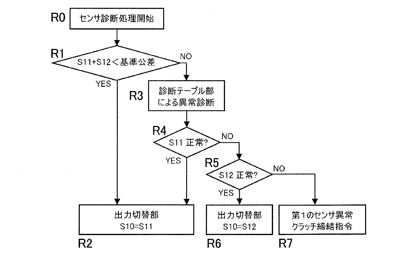
図6に、表1の診断テーブル54aのデータを利用した第1のセンサ7の診断フローを示す。この診断フローを図7と共に説明する。
まず、第1のセンサ7のニ系統の出力値S11,S12を図4の比較出力部53で加算し、その加算値と基準公差とを比較する(図6のステップR1)。
加算値が基準公差内である場合は、ニ系統の出力値S11,S12のうち、定められた出力値(図6の例では出力S11)を制御信号として選択する(R2。)
図7に示すように、第1のセンサ7の出力S11=S11nにおいて、出力比較部56での演算結果が基準公差内でない場合、直ちに診断テーブル部54の診断テーブル54aにメモリされた診断テーブルパターンでS12n,S2nの値を参照する(R3)。その結果、S11nの出力パターンが診断テーブルパターンから逸脱していなければ、その正常なS11の信号が制御信号として選択される(R4,R2)。診断テーブルパターンから逸脱しているか否かは、表1に診断テーブル54aの内容例を示すように、二系統出力センサである第1のセンサ7のニ系統の出力値S11及びS12と、回転角検出器である第2のセンサ17の出力値S2の比較によって行う。
FIG. 6 shows a diagnosis flow of the
First, the output values S11 and S12 of the two systems of the
When the added value is within the reference tolerance, a predetermined output value (output S11 in the example of FIG. 6) is selected as a control signal among the two system output values S11 and S12 (R2).
As shown in FIG. 7, in the output S11 = S11n of the
S11の出力パターンが診断テーブルパターンから逸脱していて、S12の出力パターンが診断テーブルパターンから逸脱いなければ、その正常なS12の信号が制御信号として選択される(R4,R5,R6)。また、S11nとS12nとS2nの出力値の関係が診断テーブルパターンから逸脱していれば、第1のセンサ7自体が異常と判断し、全機能を停止しクラッチ80を締結する(R4,R5,R7)。なお、フロー図では出力S11,S12のうち、S11の出力が正常であるか否かを先に判断したが、出力S12が正常であるか否かを先に判断しても良い。
If the output pattern of S11 deviates from the diagnostic table pattern and the output pattern of S12 does not deviate from the diagnostic table pattern, the normal S12 signal is selected as a control signal (R4, R5, R6). If the relationship between the output values of S11n, S12n, and S2n deviates from the diagnostic table pattern, the
図4に示す出力切替部55は、診断テーブル部54の診断結果に基づき、第1のセンサ7のニ系統の出力S11とS12のうち正常な系統を選択する。どちらも正常時な時は、たとえばS11を選択するものとする。
The
第2の制御装置52においても、第1の制御装置51と同様の構成となるため、第1の制御装置51の異常診断部53と同様にして転舵角の絶対位置を検出するセンサの異常を診断することが可能である。ただし、第1の制御装置51では、図4に示すように、第1センサ7,第2のセンサ17が用いられ、出力切替部55の出力先は、反力用モータ8を制御する反力制御部3aであるで、第2の制御装置52では、図8に示すように、第1センサ31,第2のセンサ26が用いられる。出力切替部55の出力先は、転舵用モータ25を制御する転舵制御部6aである。異常診断部53の処理は、第1の制御装置51と第2の制御装置52とで同じとなるため、対応部分に同一符号を付してその重複する説明を省略する。
Since the
上記構成によると、操舵軸11または転舵軸連動体25aに、絶対位置検出可能な回転角検出センサとして二系統出力センサ7,31を設け、この二系統出力センサ7,31は、その二系統の出力として、前記操舵軸11または前記転舵軸連動体25aの回転領域において、互いに同一の増加率で直線的に変化し、それぞれの増減方向が前記回転領域の基準位置を起点に正反対な出力値を有するものとしたため、前記異常診断部53により、二系統の出力値を比較演算することで、前記二系統出力センサのニ系統の各信号の異常と、センサ7,31自体の異常を確実に検知することが可能である。仮に一系統の信号を失陥しても他の一系統が正常であれば機能は続行可能となる。
また、前記二系統出力センサ7,31は、一つの検出機構に対しニ系統の出力回路を装備するため、機械的な要因による位相のズレは発生せず、ニ系統の出力を切り替えて使用しても電気的な位相にもズレは発生しない。
このように、センサの異常発生時における確実な診断が行え、かつ仮に一系統が失陥しても残りの系統で回転検出機能が続行可能な冗長機能を備え、この冗長機能の切替え時の電気的な位相ずれ等の問題がなく、さらに二系統出力センサ7,31の使用により、確実な診断、冗長機能、およびその冗長機能切替え時の問題解消が、センサ個数の増大を抑えて、簡易な構成の異常診断部53で経済的に行える。
According to the above configuration, the two-
Further, since the two-
In this way, it is possible to perform a reliable diagnosis when a sensor abnormality occurs, and even if one system fails, the remaining system is equipped with a redundant function that allows the rotation detection function to continue. There is no problem such as phase shift, and the use of dual-
また、前記診断テーブル部54を備えることで、前記第1のセンサ7,31の二系統の出力信号の一方の異常であるか、センサ自体の異常であるかを判定することができる。
In addition, by providing the
また、前記異常診断部53は、前記二系統出力センサである前記第1のセンサ7,31の二系統の出力信号のうち一系統の信号が異常と判断した場合に、前記二系統の出力信号のうちの異常と判断されていない方の信号である正常な信号を選択する。そのため、二系統出力センサである第1のセンサ7,31の正常な信号を用いて回転検出機能を続行し、操舵およびその操舵による転舵を続行することができる。
Further, when the
さらに、前記異常診断部53は、前記二系統出力センサである前記第1のセンサ7,31自体の異常と判断した場合に、前記クラッチ80を接続する指令を出力する構成としたため、センサ自体の異常があった場合に、ステアバイワイヤ式操舵とはならないが、操舵およびその操舵による転舵を続行することができる。
Further, since the
つぎに、この発明の他の実施形態を図9,図10と共に説明する。この実施形態は、
トー角調整機能を有するステアバイワイヤ式操舵装置に適用した例である。図9にトー角調整機能の例を示す。転舵装置32は転舵調整部33とトー角調整部34からなり、転舵機能とトー角制御機能を有する。転舵調整部33では、転舵軸19Aの一端部に雄ねじ部35が形成される点を除き、図3に示す転舵軸19と構成は同じである。
Next, another embodiment of the present invention will be described with reference to FIGS. This embodiment is
This is an example applied to a steer-by-wire steering device having a toe angle adjustment function. FIG. 9 shows an example of the toe angle adjustment function. The
トー角調整部34は、トー角調整軸であるスプライン軸36と、このスプライン軸36に挿入されるスプラインナット37が主要部品とされる。スプライン軸36の一端部には雌ねじ部36aが形成され、転舵軸19Aの一端部に形成した雄ねじ部35と螺合してねじ機構38が形成される。スプライン軸36は、例えばボールスプライン軸であり、その外周には軸方向に複数の溝36bが形成され、スプラインナット37には図示しない転動体の循環機構が形成される。溝36bを図示しない転動体(ボール)が転がることで直動案内と回転トルクを伝達可能とされる。
The toe
スプラインナット37は軸受39によって回転自在に支持される。また、スプラインナット37には第5歯車40が固定される。トー角制御用モータ41のロータの一端部には、回転角を検出する回転検出器である第2のセンサ42が固定される。第2のセンサ42は、たとえばレゾルバである。レゾルバのロータ42aをトー角制御用モータ41のロータに固定し、ゾゾルバのステータ42bをケースに固定する。
The
トー角調整用モータ41のロータの他端には第6歯車43が固定され、第5歯車40と第6歯車43が噛合する。トー角調整用モータ41が回転すると、第5、第6歯車40、43を介してスプラインナット37が回転する。それに合わせてねじ機構38の雌ねじ部36aが回転することで、スプライン軸36が転舵軸19Aに対して軸方向に移動してトー角を調整する。
トー角調整用モータ41を回転させると、スプライン軸36側に装着される片側の前輪のみトー角が調整される。左右の前輪4、5のトー角を変更する場合には、転舵用モータ25とトー角調整用モータ41の2つのモータを調整して、転舵軸19Aと、スプライン軸36の軸方向位置をそれぞれ調整することで、トーイン、トーアウトの制御が可能となる。
A
When the toe
トー角調整用モータ41のロータには、スプライン軸36の絶対位置を検出する位置検出器である二系統出力センサからなる第1のセンサ44が接続される。具体的には、トー角調整用モータ41のロータと一体のトー角調整系回転体41aに対して第1のセンサ44が設けられる。第2のセンサ44の内部には減速機(図示なし)とポテンショメータ(図示なし)を備える。トー角調整用モータ41のフル転舵時の回転数を1回転以下に減速し、減速後の出力を回転型のポテンショメータに入力することでスプライン軸36の絶対位置を検出する。ここでは、間接的にスプライン軸36の絶対位置を検出しているが、スプライン軸36を直接絶対位置検出の方法は問わない。
The rotor of the toe
この構成のトー角調整機能を有するステアバイワイヤ式操舵装置において、トー角調整部34を制御する第3の制御装置57を図1の電子制御ユニット50に設ける。第1の制御装置51と第2の制御装置52は、第2の制御装置52の制御の対象が図9のステアバイワイヤ式操舵装置の転舵調整部33になる他は同じであり、第1の制御装置51および第2の制御装置52における異常診断部53およびセンサ類は、第1の実施形態と同様に設ける。
In the steer-by-wire type steering apparatus having the toe angle adjusting function of this configuration, a
トー角調整用の第3の制御装置57においても、第1の制御装置51の異常診断部53と同様にしてトー角の絶対位置を検出するセンサの異常を診断することが可能である。ただし、第1の制御装置51では、図4に示すように、第1センサ7,第2のセンサ17が用いられ、出力切替部55の出力先は、反力用モータ8を制御する反力制御部3aであるが、第3の制御装置57では、図10に示すように、第1センサ44,第2のセンサ42が用いられ、出力切替部55の出力先は、トー角を制御するトー角制御部58である。異常診断部53の処理は、第1の制御装置51と第2の制御装置52とで同じとなるため、対応部分に同一符号を付してその重複する説明を省略する。
このように、第1の実施形態と同様の構成の第3の制御装置57をトー角制御用として付加することでトー角調整部34の二系統出力センサからなる絶対位置センサである第1のセンサ44の異常診断が可能となる。
In the
As described above, the
1…ステアバイワイヤ式操舵装置
2…ステアリングホイール
3…反力付与部
6…転舵装置
11…操舵軸
7…第1のセンサ(二系統出力センサ)
17…第2のセンサ
19…転舵軸
25a…モータロータ軸(転舵用駆動伝達体)
26…第2のセンサ
31…第1のセンサ(二系統出力センサ)
33…転舵調整部
34…トー角調整部
42…第2のセンサ
41a…モータロータ軸(トー角調整系回転体)
44…第1のセンサ(二系統出力センサ)
53…異常診断部
54…診断テーブル部
54a…診断テーブル
54b…テーブル使用判定部
80…クラッチ
DESCRIPTION OF SYMBOLS 1 ... Steer-by-wire
17 ...
26 ...
33 ...
44. First sensor (dual output sensor)
53 ...
Claims (5)
前記ステアリングホイールの操舵軸、または前記転舵装置が有する転舵軸連動体の回転角を検出し、絶対位置が検出可能で二系統の出力部を有する二系統出力センサを有し、
前記二系統出力センサの二系統の出力値は、前記操舵軸または前記転舵軸連動体の回転領域において、互いに同一の増加率で直線的に変化し、それぞれの増減方向が前記回転領域の基準位置を起点に正反対な出力値を有し、
前記二系統出力センサのセンサ信号の二系統の出力値を比較演算することで、前記二系統出力センサの信号異常を診断する異常診断部を有するステアバイワイヤ式操舵装置の制御装置。 A reaction force applying unit that applies a steering reaction force to a steering wheel of a vehicle, a turning device that makes a turning angle variable, a connection that mechanically transmits an operation amount of the steering wheel to the turning device, and In a vehicle steering control device that controls a steer-by-wire steering device including a clutch that can be released,
Detecting the rotation angle of the steering shaft of the steering wheel, or the turning shaft interlocking body of the turning device, and having a two-system output sensor that can detect the absolute position and has two systems of output units;
The output values of the two systems of the two-system output sensor change linearly at the same increase rate in the rotation region of the steering shaft or the steered shaft interlocking body, and the respective increasing / decreasing directions are the reference of the rotation region. It has the opposite output value from the position as the starting point,
A control device for a steer-by-wire steering apparatus having an abnormality diagnosis unit that diagnoses a signal abnormality of the two-system output sensor by comparing and calculating output values of two systems of sensor signals of the two-system output sensor.
前記異常診断部は、この異常診断部に入力される前記二系統出力センサである第1のセンサの二系統の出力値と前記第2センサの出力値の組み合わせによって異常であるか否かを定めた診断テーブルと、この診断テーブルを用いて前記第1のセンサの二系統の出力信号の一方の異常か、センサ自体の異常か、を判定するテーブル使用判定部とからなる診断テーブル部を備えたステアバイワイヤ式操舵装置の制御装置。 The control device for the steer-by-wire type steering apparatus according to claim 1, further comprising a second sensor that detects a rotation angle of the steering shaft of the steering wheel or the turning shaft interlocking body,
The abnormality diagnosing unit determines whether or not an abnormality is caused by a combination of output values of the two systems of the first sensor and the output values of the second sensor that are the two-system output sensors input to the abnormality diagnosing unit. A diagnostic table unit including a diagnostic table and a table usage determining unit that determines whether one of the two output signals of the first sensor or the sensor itself is abnormal using the diagnostic table. Control device for steer-by-wire steering system.
前記トー角調整部側の二系統出力センサの二系統の出力値は、前記トー角調整系回転体の回転領域において、互いに同一の増加率で直線的に変化し、それぞれの増減方向が前記回転領域の基準位置を起点に正反対な出力値を有し、
前記トー角調整部側の二系統出力センサのセンサ信号の二系統の出力値を比較演算することで、前記二系統出力センサの信号異常を診断する異常診断部を設けたステアバイワイヤ式操舵装置の制御装置。 5. The control device for the steer-by-wire type steering apparatus according to claim 1, wherein the steer-by-wire type steering apparatus includes a toe angle adjustment unit that adjusts a toe angle, A toe angle adjusting system rotating body provided on the toe angle adjusting system rotator is detected, the absolute position can be detected and a toe angle adjusting unit side two-system output sensor having a two-system output unit is provided,
The output values of the two systems of the two-system output sensor on the toe angle adjusting unit side change linearly at the same increase rate in the rotation region of the toe angle adjusting system rotating body, and the respective increasing / decreasing directions are the rotations. Has the opposite output value starting from the reference position of the area,
A steer-by-wire type steering apparatus provided with an abnormality diagnosis unit for diagnosing signal abnormality of the two-system output sensor by comparing and calculating the output values of the two systems of the sensor signal of the two-system output sensor on the toe angle adjusting unit side Control device.
Priority Applications (1)
| Application Number | Priority Date | Filing Date | Title |
|---|---|---|---|
| JP2013199406A JP2015063270A (en) | 2013-09-26 | 2013-09-26 | Control device of steering-by-wire type steering device |
Applications Claiming Priority (1)
| Application Number | Priority Date | Filing Date | Title |
|---|---|---|---|
| JP2013199406A JP2015063270A (en) | 2013-09-26 | 2013-09-26 | Control device of steering-by-wire type steering device |
Publications (1)
| Publication Number | Publication Date |
|---|---|
| JP2015063270A true JP2015063270A (en) | 2015-04-09 |
Family
ID=52831549
Family Applications (1)
| Application Number | Title | Priority Date | Filing Date |
|---|---|---|---|
| JP2013199406A Pending JP2015063270A (en) | 2013-09-26 | 2013-09-26 | Control device of steering-by-wire type steering device |
Country Status (1)
| Country | Link |
|---|---|
| JP (1) | JP2015063270A (en) |
Cited By (27)
| Publication number | Priority date | Publication date | Assignee | Title |
|---|---|---|---|---|
| JP2018518412A (en) * | 2015-05-26 | 2018-07-12 | ロベルト・ボッシュ・ゲゼルシャフト・ミト・ベシュレンクテル・ハフツングRobert Bosch Gmbh | Apparatus and method for driving a car |
| CN108698637A (en) * | 2016-02-12 | 2018-10-23 | 日本精工株式会社 | Steering controller for vehicle |
| EP3626584A1 (en) | 2018-09-18 | 2020-03-25 | KNORR-BREMSE Systeme für Nutzfahrzeuge GmbH | Steering system for a vehicle |
| JP2020125997A (en) * | 2019-02-05 | 2020-08-20 | 日本電産モビリティ株式会社 | Electric motor control device and electric motor control method |
| CN113269952A (en) * | 2020-02-14 | 2021-08-17 | 美光科技公司 | Drive-by-wire sensor monitoring in a vehicle |
| US11361552B2 (en) | 2019-08-21 | 2022-06-14 | Micron Technology, Inc. | Security operations of parked vehicles |
| US11409654B2 (en) | 2019-09-05 | 2022-08-09 | Micron Technology, Inc. | Intelligent optimization of caching operations in a data storage device |
| US11436076B2 (en) | 2019-09-05 | 2022-09-06 | Micron Technology, Inc. | Predictive management of failing portions in a data storage device |
| US11435946B2 (en) | 2019-09-05 | 2022-09-06 | Micron Technology, Inc. | Intelligent wear leveling with reduced write-amplification for data storage devices configured on autonomous vehicles |
| US11498388B2 (en) | 2019-08-21 | 2022-11-15 | Micron Technology, Inc. | Intelligent climate control in vehicles |
| US11586943B2 (en) | 2019-08-12 | 2023-02-21 | Micron Technology, Inc. | Storage and access of neural network inputs in automotive predictive maintenance |
| US11586194B2 (en) | 2019-08-12 | 2023-02-21 | Micron Technology, Inc. | Storage and access of neural network models of automotive predictive maintenance |
| US11635893B2 (en) | 2019-08-12 | 2023-04-25 | Micron Technology, Inc. | Communications between processors and storage devices in automotive predictive maintenance implemented via artificial neural networks |
| US11650746B2 (en) | 2019-09-05 | 2023-05-16 | Micron Technology, Inc. | Intelligent write-amplification reduction for data storage devices configured on autonomous vehicles |
| CN116161110A (en) * | 2023-03-10 | 2023-05-26 | 浙江吉利控股集团有限公司 | Steering-by-wire system, redundancy backup method and device thereof, storage medium and vehicle |
| US11693562B2 (en) | 2019-09-05 | 2023-07-04 | Micron Technology, Inc. | Bandwidth optimization for different types of operations scheduled in a data storage device |
| US11702086B2 (en) | 2019-08-21 | 2023-07-18 | Micron Technology, Inc. | Intelligent recording of errant vehicle behaviors |
| US11709625B2 (en) | 2020-02-14 | 2023-07-25 | Micron Technology, Inc. | Optimization of power usage of data storage devices |
| US11748626B2 (en) | 2019-08-12 | 2023-09-05 | Micron Technology, Inc. | Storage devices with neural network accelerators for automotive predictive maintenance |
| US11775816B2 (en) | 2019-08-12 | 2023-10-03 | Micron Technology, Inc. | Storage and access of neural network outputs in automotive predictive maintenance |
| US11830296B2 (en) | 2019-12-18 | 2023-11-28 | Lodestar Licensing Group Llc | Predictive maintenance of automotive transmission |
| US11853863B2 (en) | 2019-08-12 | 2023-12-26 | Micron Technology, Inc. | Predictive maintenance of automotive tires |
| US12061971B2 (en) | 2019-08-12 | 2024-08-13 | Micron Technology, Inc. | Predictive maintenance of automotive engines |
| US12210401B2 (en) | 2019-09-05 | 2025-01-28 | Micron Technology, Inc. | Temperature based optimization of data storage operations |
| US12249189B2 (en) | 2019-08-12 | 2025-03-11 | Micron Technology, Inc. | Predictive maintenance of automotive lighting |
| US12443387B2 (en) | 2019-08-21 | 2025-10-14 | Micron Technology, Inc. | Intelligent audio control in vehicles |
| US12497055B2 (en) | 2019-08-21 | 2025-12-16 | Micron Technology, Inc. | Monitoring controller area network bus for vehicle control |
-
2013
- 2013-09-26 JP JP2013199406A patent/JP2015063270A/en active Pending
Cited By (34)
| Publication number | Priority date | Publication date | Assignee | Title |
|---|---|---|---|---|
| JP2018518412A (en) * | 2015-05-26 | 2018-07-12 | ロベルト・ボッシュ・ゲゼルシャフト・ミト・ベシュレンクテル・ハフツングRobert Bosch Gmbh | Apparatus and method for driving a car |
| CN108698637A (en) * | 2016-02-12 | 2018-10-23 | 日本精工株式会社 | Steering controller for vehicle |
| CN108698637B (en) * | 2016-02-12 | 2021-02-26 | 日本精工株式会社 | Vehicle steering control device |
| US11993306B2 (en) | 2018-09-18 | 2024-05-28 | Knorr-Bremse Systeme Fuer Nutzfahrzeuge Gmbh | Steering system for a vehicle |
| EP3626584A1 (en) | 2018-09-18 | 2020-03-25 | KNORR-BREMSE Systeme für Nutzfahrzeuge GmbH | Steering system for a vehicle |
| WO2020057970A1 (en) | 2018-09-18 | 2020-03-26 | Knorr-Bremse Systeme für Nutzfahrzeuge GmbH | Steering system for a vehicle |
| JP2020125997A (en) * | 2019-02-05 | 2020-08-20 | 日本電産モビリティ株式会社 | Electric motor control device and electric motor control method |
| US12061971B2 (en) | 2019-08-12 | 2024-08-13 | Micron Technology, Inc. | Predictive maintenance of automotive engines |
| US12249189B2 (en) | 2019-08-12 | 2025-03-11 | Micron Technology, Inc. | Predictive maintenance of automotive lighting |
| US11748626B2 (en) | 2019-08-12 | 2023-09-05 | Micron Technology, Inc. | Storage devices with neural network accelerators for automotive predictive maintenance |
| US11586943B2 (en) | 2019-08-12 | 2023-02-21 | Micron Technology, Inc. | Storage and access of neural network inputs in automotive predictive maintenance |
| US11586194B2 (en) | 2019-08-12 | 2023-02-21 | Micron Technology, Inc. | Storage and access of neural network models of automotive predictive maintenance |
| US11635893B2 (en) | 2019-08-12 | 2023-04-25 | Micron Technology, Inc. | Communications between processors and storage devices in automotive predictive maintenance implemented via artificial neural networks |
| US11853863B2 (en) | 2019-08-12 | 2023-12-26 | Micron Technology, Inc. | Predictive maintenance of automotive tires |
| US11775816B2 (en) | 2019-08-12 | 2023-10-03 | Micron Technology, Inc. | Storage and access of neural network outputs in automotive predictive maintenance |
| US12443387B2 (en) | 2019-08-21 | 2025-10-14 | Micron Technology, Inc. | Intelligent audio control in vehicles |
| US11498388B2 (en) | 2019-08-21 | 2022-11-15 | Micron Technology, Inc. | Intelligent climate control in vehicles |
| US11361552B2 (en) | 2019-08-21 | 2022-06-14 | Micron Technology, Inc. | Security operations of parked vehicles |
| US12497055B2 (en) | 2019-08-21 | 2025-12-16 | Micron Technology, Inc. | Monitoring controller area network bus for vehicle control |
| US11702086B2 (en) | 2019-08-21 | 2023-07-18 | Micron Technology, Inc. | Intelligent recording of errant vehicle behaviors |
| US11650746B2 (en) | 2019-09-05 | 2023-05-16 | Micron Technology, Inc. | Intelligent write-amplification reduction for data storage devices configured on autonomous vehicles |
| US11409654B2 (en) | 2019-09-05 | 2022-08-09 | Micron Technology, Inc. | Intelligent optimization of caching operations in a data storage device |
| US11693562B2 (en) | 2019-09-05 | 2023-07-04 | Micron Technology, Inc. | Bandwidth optimization for different types of operations scheduled in a data storage device |
| US12450010B2 (en) | 2019-09-05 | 2025-10-21 | Lodestar Licensing Group Llc | Intelligent wear leveling with reduced write-amplification for data storage devices configured on autonomous vehicles |
| US11436076B2 (en) | 2019-09-05 | 2022-09-06 | Micron Technology, Inc. | Predictive management of failing portions in a data storage device |
| US12210401B2 (en) | 2019-09-05 | 2025-01-28 | Micron Technology, Inc. | Temperature based optimization of data storage operations |
| US11435946B2 (en) | 2019-09-05 | 2022-09-06 | Micron Technology, Inc. | Intelligent wear leveling with reduced write-amplification for data storage devices configured on autonomous vehicles |
| US11830296B2 (en) | 2019-12-18 | 2023-11-28 | Lodestar Licensing Group Llc | Predictive maintenance of automotive transmission |
| US12518570B2 (en) | 2019-12-18 | 2026-01-06 | Lodestar Licensing Group Llc | Predictive maintenance of automotive transmission |
| US11531339B2 (en) | 2020-02-14 | 2022-12-20 | Micron Technology, Inc. | Monitoring of drive by wire sensors in vehicles |
| US11709625B2 (en) | 2020-02-14 | 2023-07-25 | Micron Technology, Inc. | Optimization of power usage of data storage devices |
| CN113269952B (en) * | 2020-02-14 | 2023-10-10 | 美光科技公司 | Method for predictive maintenance of a vehicle, data storage device and vehicle |
| CN113269952A (en) * | 2020-02-14 | 2021-08-17 | 美光科技公司 | Drive-by-wire sensor monitoring in a vehicle |
| CN116161110A (en) * | 2023-03-10 | 2023-05-26 | 浙江吉利控股集团有限公司 | Steering-by-wire system, redundancy backup method and device thereof, storage medium and vehicle |
Similar Documents
| Publication | Publication Date | Title |
|---|---|---|
| JP2015063270A (en) | Control device of steering-by-wire type steering device | |
| JP5816019B2 (en) | Control device for steer-by-wire steering system with redundancy function | |
| US9975572B2 (en) | In-vehicle device controller and power steering device | |
| US10214235B2 (en) | Power steering device and power steering device control unit | |
| WO2015040961A1 (en) | Power steering device and control device for vehicle-mounted instrument | |
| US9643642B2 (en) | Vehicle steering apparatus | |
| US9228910B2 (en) | Abnormality diagnosis apparatus and abnormality diagnosis method for torque sensor | |
| CN101353051A (en) | Power steering device with fault detection device for rotation angle sensor | |
| US20170341679A1 (en) | Vehicle steering device | |
| US20200062293A1 (en) | Steering control apparatus | |
| WO2016194885A1 (en) | Rear wheel turning control apparatus | |
| JP2015093535A (en) | Rear wheel steering control device with abnormality monitor function | |
| KR20130098815A (en) | Reducer of electric power steering apparatus | |
| JP6437238B2 (en) | Rear wheel steering control device | |
| JP6282452B2 (en) | Vehicle steering control device | |
| JP2010214978A (en) | Steer-by-wire steering device | |
| CN112955366B (en) | Method for determining a state value of a wheel drive module | |
| KR101784751B1 (en) | Finding method for locked steering apparatus and navigation method by the same and unlocking process for the locked steering apparatus by the same | |
| JP3729015B2 (en) | Vehicle steering device | |
| JP5076564B2 (en) | Drive control device and steering control device using the same | |
| JP6407564B2 (en) | Rear wheel steering control device | |
| JP6591283B2 (en) | Vehicle steering device | |
| KR20230091623A (en) | Experimental apparatus for controllability evaluation of the fail-safe electric power steering device | |
| JP5332213B2 (en) | Steer-by-wire system diagnosis apparatus and steer-by-wire system diagnosis method | |
| JP6214984B2 (en) | Control device for rear wheel steering device |