JP2015054603A - Object detection device - Google Patents
Object detection device Download PDFInfo
- Publication number
- JP2015054603A JP2015054603A JP2013188763A JP2013188763A JP2015054603A JP 2015054603 A JP2015054603 A JP 2015054603A JP 2013188763 A JP2013188763 A JP 2013188763A JP 2013188763 A JP2013188763 A JP 2013188763A JP 2015054603 A JP2015054603 A JP 2015054603A
- Authority
- JP
- Japan
- Prior art keywords
- point
- alarm
- position information
- moving object
- determination
- Prior art date
- Legal status (The legal status is an assumption and is not a legal conclusion. Google has not performed a legal analysis and makes no representation as to the accuracy of the status listed.)
- Pending
Links
Images


Landscapes
- Traffic Control Systems (AREA)
Abstract
【課題】所定の車両状況において移動物と静止物を判別可能な対象物検知装置を提供すること。
【解決手段】対象物から反射するレーダーに基づき対象物を検知する対象物検知装置100であって、対象物の位置情報を記録する位置記録手段22と、位置情報取得手段が取得した自車両の現在の位置が予め定めた場所である場合に、前記位置記録手段が記録した同じ対象物の過去の位置情報に基づき、対象物が静止物か否かを判定する判定手段232と、 前記判定手段の判定結果に基づき警報手段14を制御する警報制御手段233と、を有することを特徴とする。
【選択図】図11An object detection apparatus capable of discriminating a moving object and a stationary object in a predetermined vehicle situation.
An object detection apparatus 100 for detecting an object based on radar reflected from the object, the position recording means 22 for recording the position information of the object, and the own vehicle acquired by the position information acquisition means. When the current position is a predetermined place, based on past position information of the same object recorded by the position recording means, a determination means 232 for determining whether the object is a stationary object; and the determination means And alarm control means 233 for controlling the alarm means 14 based on the determination result.
[Selection] Figure 11
Description
本発明は、対象物から反射するレーダーに基づき対象物を検知する対象物検知装置に関する。 The present invention relates to an object detection device that detects an object based on radar reflected from the object.
自車両周辺の移動物を検出して運転者に注意喚起する運転支援が知られている。車両の進行方向の障害物をレーダやカメラなどで検出するだけでなく、運転者の死角となる方向の移動物を検出して警報などを出力する技術も実用化されつつある(例えば、特許文献1参照。)。特許文献1には、自車両の位置と自車両の移動方向を検知して、障害物を検知すると方向を変更する車両用障害物検出装置が開示されている。自車位置を検出することで、例えば交差点や高速道路の合流地点等のように自車両の走行道路に対して交差する交差道路を検出し、検知した道路構成に対する自車両の位置および移動方向に基づき、例えばミリ波やレーザ等の物体検知手段の検知方向を設定する。
Driving assistance that detects moving objects around the host vehicle and alerts the driver is known. In addition to detecting obstacles in the traveling direction of a vehicle with a radar or a camera, a technique for detecting a moving object in a direction that becomes a driver's blind spot and outputting an alarm or the like is being put into practical use (for example, Patent Literature 1).
しかしながら、従来の障害物の検知方法では、移動物と静止物を判別できない場合があり、適切な注意喚起が困難な状況があるという問題がある。 However, in the conventional obstacle detection method, there is a case where it is difficult to distinguish between a moving object and a stationary object, and there is a problem that it is difficult to appropriately call attention.
例えば、合流地点では自車両のレーンと隣接したレーンに合流車両が進入するが、自車両の後側方に合流車両が合流した場合、後側方の合流車両を静止物として検知してしまう場合がある。 For example, when a merging vehicle enters a lane adjacent to the lane of the host vehicle at the merging point, but the merging vehicle joins the rear side of the host vehicle, the merging vehicle on the rear side is detected as a stationary object. There is.
本発明は、上記課題に鑑み、移動物と静止物の判別精度が向上した対象物検知装置を提供することを目的とする。 An object of this invention is to provide the target object detection apparatus with which the discrimination | determination precision of a moving object and a stationary object improved in view of the said subject.
本発明は、対象物から反射するレーダーに基づき対象物を検知する対象物検知装置であって、対象物の位置情報を記録する位置記録手段と、位置情報取得手段が取得した自車両の現在の位置が予め定めた場所である場合に、前記位置記録手段が記録した同じ対象物の過去の位置情報に基づき、対象物が静止物か否かを判定する判定手段と、前記判定手段の判定結果に基づき警報手段を制御する警報制御手段と、を有することを特徴とする。 The present invention is an object detection device that detects an object based on radar reflected from the object, and includes a position recording unit that records position information of the object, and a current vehicle acquired by the position information acquisition unit. When the position is a predetermined place, based on past position information of the same object recorded by the position recording unit, a determination unit that determines whether or not the object is a stationary object, and a determination result of the determination unit And alarm control means for controlling the alarm means based on the above.
移動物と静止物の判別精度が向上した対象物検知装置を提供することができる。 It is possible to provide a target object detection apparatus with improved accuracy of discrimination between moving objects and stationary objects.
以下、本発明を実施するための形態について図面を参照しながら説明する。しかしながら、本発明の技術的範囲が、本実施の形態に限定されるものではない。 Hereinafter, embodiments for carrying out the present invention will be described with reference to the drawings. However, the technical scope of the present invention is not limited to this embodiment.
〔課題について〕
まず、対象物検知装置は、BSM(Blind Spot Monitoring−System)とLCA(Lane Change Assist)という2つの検知機能を有している。
BSM:死角に存在する車両を検出する。検知エリアは車両の後側方の近距離範囲であり、この検知エリアをBSMエリアという場合がある。
LCA:相対速度の大きい移動物を検出する。検知エリアはBSMよりも遠方の車両の後側方であり、この検知エリアをLCAエリアという場合がある。
[About assignment]
First, the object detection apparatus has two detection functions of BSM (Blind Spot Monitoring-System) and LCA (Lane Change Assist).
BSM: Detects a vehicle in a blind spot. The detection area is a short distance range on the rear side of the vehicle, and this detection area may be referred to as a BSM area.
LCA: A moving object with a high relative speed is detected. The detection area is the rear side of the vehicle farther than the BSM, and this detection area may be referred to as an LCA area.
図1を用いて、本実施形態の対象物検知装置が解決する課題等について説明する。図1(a)は移動物を静止物と判断してしまう状況を示している。自車両は左後側方の対象物をレーダで周期的に検出する対象物検知装置を搭載している。白丸は静止物の過去の予測点であり、黒丸は静止物の最新の予測点である。予測点については後述する。 The problem etc. which the target object detection apparatus of this embodiment solves are demonstrated using FIG. FIG. 1A shows a situation where a moving object is determined as a stationary object. The host vehicle is equipped with an object detection device that periodically detects an object on the left rear side with a radar. White circles are past prediction points for stationary objects, and black circles are the latest prediction points for stationary objects. The prediction points will be described later.
対象物検知装置の静止物又は移動物の認識手順として、BSMでは、連続して真横で反射し続ける対象物を静止物として認識している。 As a procedure for recognizing a stationary object or a moving object of the object detection apparatus, BSM recognizes an object that continues to be reflected directly beside it as a stationary object.
しかしながら、このように合流地点の手前に壁などの静止物が敷設されている場合、静止物と移動物の判別が困難になるおそれがある。自車両は連続して真横で反射し続ける静止物(壁)を静止物と認識しているが、この判定状態のまま合流地点で自車両とほぼ同じ速度の合流車両が合流した場合、自車両は真横点を静止物と認識したままになる。これは、短時間では移動物の特徴量が出にくいためと、頻繁な警報を抑制するため静止物と認識した過去の判定状態が維持される傾向にあるためである。したがって、合流車を移動物と認識するのが遅れ警報されない場合がある。 However, when a stationary object such as a wall is laid in front of the junction point in this way, it may be difficult to distinguish between the stationary object and the moving object. The host vehicle recognizes a stationary object (wall) that continues to be reflected directly beside it as a stationary object. However, if a merging vehicle at approximately the same speed as the host vehicle merges at this merging point, Remains to recognize the right side point as a stationary object. This is because the feature amount of the moving object is difficult to appear in a short time, and the past determination state recognized as a stationary object tends to be maintained in order to suppress frequent alarms. Therefore, there is a case where it is not delayed for recognizing the merged vehicle as a moving object.
図1(b)は、静止物を移動物と判断してしまう状況の一例を示している。白三角は移動物の過去の予測点であり、黒三角は移動物の最新の予測点である。道路に沿ってガードレールが存在するが、LCAによりカーブ進入前は後方の他車両を検出している。車両が右旋回のカーブに進入すると、遠方でのガードレールの反射点が存在するため、ガードレールをそれまで検出していた他車両として検出する場合がある。また、車両がカーブ出口に向かうにつれて、ガードレールの反射点を相対速度が大きい移動物(自車両に接近してくる移動物)として検知する場合がある。すなわち、ガードレール等からの反射波は、図の点線の枠内に示すように、自車両から見ると後側方から徐々に接近する移動物として検出されてしまう。このため、対象物検知装置は、移動物が存在しないのにガードレールや壁の静止物を、移動物と判定して警報する場合がある。 FIG. 1B shows an example of a situation where a stationary object is determined as a moving object. The white triangle is the past prediction point of the moving object, and the black triangle is the latest prediction point of the moving object. There are guardrails along the road, but other vehicles behind are detected by LCA before entering the curve. When the vehicle enters a right turn curve, there is a reflection point of the guard rail at a distance, so the guard rail may be detected as another vehicle that has been detected so far. In addition, as the vehicle heads toward the curve exit, the reflection point of the guardrail may be detected as a moving object with high relative speed (moving object approaching the host vehicle). That is, a reflected wave from a guardrail or the like is detected as a moving object that gradually approaches from the rear side when viewed from the host vehicle, as shown in a dotted frame in the figure. For this reason, the object detection device may determine that a stationary object such as a guardrail or a wall is a moving object and alerts it even when there is no moving object.
本実施形態の対象物検知装置は、図1(a)(b)のような状況で静止物と移動物とをより高精度に判別することを可能にする。 The object detection device of the present embodiment makes it possible to discriminate between a stationary object and a moving object with higher accuracy in the situation as shown in FIGS.
〔対象物検知装置の概略〕
本実施形態の対象物検知装置は、以下のようにして移動物を静止物として認識したり、静止物を移動物として認識することを抑制する。まず、図1(a)のように移動物を静止物と判断してしまう場合について説明する。
(1)対象物検知装置は、GNSS(Global Navigation Satellite System)などで自車両の位置情報を取得しておく。
(2)図1(a)のような合流部においては壁が途切れるため観測点は検出されない。このため、予測点が不連続に検出されるか、予測点の位置にばらつきが生じる。一方、合流車が自車両とほぼ等速で合流した場合、対象物検知装置は自車両の真横で静止物を検出し始める。対象物検知装置は、位置情報から合流地点であることを検出して、予測点の特徴量(不連続時間、ばらつきなど)を用いて、静止物と判定されていた対象物(他車両)を移動物に切り替える。
(3)対象物が移動物であると判定されることで、BSMエリア内に移動物が検出されるため、対象物検知装置は運転者に警報を出力することができる。
[Outline of object detection device]
The object detection apparatus of this embodiment suppresses recognizing a moving object as a stationary object or recognizing a stationary object as a moving object as follows. First, a case where a moving object is determined to be a stationary object as shown in FIG.
(1) The target object detection apparatus acquires the position information of the host vehicle using a GNSS (Global Navigation Satellite System) or the like.
(2) The observation point is not detected because the wall is interrupted at the junction as shown in FIG. For this reason, the prediction points are detected discontinuously or the positions of the prediction points vary. On the other hand, when the merging vehicle merges with the host vehicle at a substantially constant speed, the object detection device starts detecting a stationary object directly beside the host vehicle. The target object detection device detects a target point (another vehicle) that has been determined to be a stationary object by detecting that it is a merging point from position information and using the feature amount (discontinuous time, variation, etc.) of the predicted point. Switch to moving objects.
(3) Since the moving object is detected in the BSM area by determining that the object is a moving object, the object detection device can output an alarm to the driver.
このように合流地点で後側方に他車両が合流した場合、予測点の特徴量に基づき静止物から移動物への入れ替わりを判断するので、警報遅れ等を抑制してBSMエリアを走行する合流車両の存在を警報できる。 In this way, when another vehicle joins to the rear side at the joining point, the switching from the stationary object to the moving object is judged based on the feature value of the predicted point, so the joining of traveling in the BSM area while suppressing alarm delay etc. The presence of a vehicle can be warned.
次に、図1(b)のように静止物を移動物と判断してしまう場合について説明する。
(1)対象物検知装置は、対象物検知装置はGNSSなどで自車両の位置情報を取得しておく。
(2)自車の現在位置がカーブ付近の場合、対象物検知装置はLCAによる警報を禁止する。
(3)ガードレール等からの反射波が後側方から徐々に接近する移動物として判定された場合、警報が禁止されているので警報することを抑制できる。
Next, a case where a stationary object is determined as a moving object as shown in FIG.
(1) The object detection device acquires the position information of the host vehicle using GNSS or the like.
(2) When the current position of the vehicle is near a curve, the object detection device prohibits an alarm by LCA.
(3) When a reflected wave from a guardrail or the like is determined as a moving object that gradually approaches from the rear side, an alarm can be suppressed because an alarm is prohibited.
一方、LCAエリアで検知された移動体が実際に、後側方から徐々に接近する場合がある。この場合、警報すべきなので、対象物検知装置は以下のように動作する。
(1)対象物検知装置は、対象物検知装置はGNSSなどで自車両の位置情報を取得しておく。
(2´)自車の現在位置がカーブ付近の場合、対象物検知装置はLCAによる警報を禁止する。対象物検知装置はLCAエリアで対象物を検知したことを記録しておく。
(3´)対象物がBSMエリアで検知された場合、該対象物がLCAエリアで検知された対象物であれば移動体であると判定して警報する。
On the other hand, the mobile body detected in the LCA area may actually approach gradually from the rear side. In this case, since an alarm should be given, the object detection device operates as follows.
(1) The object detection device acquires the position information of the host vehicle using GNSS or the like.
(2 ′) When the current position of the vehicle is near the curve, the object detection device prohibits an alarm by LCA. The object detection device records that the object is detected in the LCA area.
(3 ′) When an object is detected in the BSM area, if the object is an object detected in the LCA area, it is determined that the object is a moving body and an alarm is issued.
このように、カーブで移動物が静止物に入れ替わった場合には静止物に対し警報することを抑制でき、移動物がそのまま接近した場合はLCAエリアからBSMエリアで連続的に対象物が検知されるか否かにより警報することができる。 In this way, when a moving object is replaced with a stationary object by a curve, it is possible to suppress alarming the stationary object, and when the moving object approaches as it is, the object is continuously detected from the LCA area to the BSM area. An alarm can be issued depending on whether or not.
〔構成例〕
図2は、対象物検知装置のシステム構成図の一例を示す。対象物検知装置100では、レーダー装置11、運転支援ECU(Electronic Control Unit)13、ナビECU12、作動デバイス14、及び、センサ類(ヨーレートセンサ15、車輪速センサ16、操舵角センサ17)がCAN(Controller Area Network)などの車載ネットワークを介して接続されている。レーダー装置11は、後述するように、対象物までの距離、相対速度、方位及び反射電力(以下、これらをまとめて物標情報という場合がある)を周期的に(例えば100ミリ秒)検出し運転支援ECU13に送信している。距離と方位から自車両に対するターゲットの相対的な位置が求められる。
[Configuration example]
FIG. 2 shows an example of a system configuration diagram of the object detection apparatus. In the
また、本実施形態のレーダー装置11は側方から後側方の対象物を検知する。レーダー装置11の電波の送受信部は、樹脂など電波を通過させる素材で作成されている車両の後方バンパの左端コーナーと右端コーナーの内側にそれぞれ配置されている。レーダーの送信方向の中心は、車軸と平行な方向に対し例えば45〜70度程度となるように配置されている。照射角度(レーダーの検出範囲)は例えば90〜120度など、設計できる。仰角はほぼゼロ(路面に平行)である。このようなレーダーの照射範囲により並走走行車両を検出できる。なお、自車両の前方の対象物を検知するレーダー装置11がさらに取り付けられていてもよい。
Further, the
レーダー装置11は、例えばFMCW(Frequency Modulated Continuous Wave)レーダーやパルスレーダーである。レーダー装置11は、送信信号と受信信号をミキサーでミキシングすることで、受信アンテナ毎にビート信号を生成する。送信信号が送信されてから受信信号が受信されるまでの時間は対象物との距離に比例し、またビート信号の周波数は相対速度によりシフトする。よって、ビート信号を例えばFFT解析することで距離及び相対速度が得られる。なお、レーダー装置11は、BSMとLCAに適した周波数や周波数分布のレーダーを自動的に切り替えながら送信している。これにより、運転者としては意識することなく、BSMエリアとLCAエリアのそれぞれから移動物が検出される。
The
対象物障害物の(方位θ)は、モノパルス方式、DBF(Digital Beam Forming)処理、MUSIC(Multiple Signal Classification)解析、又は、Capon解析などにより求めることができる。 The (direction θ) of the target obstacle can be obtained by a monopulse method, DBF (Digital Beam Forming) processing, MUSIC (Multiple Signal Classification) analysis, Capon analysis, or the like.
センサ類は、例えば、ヨーレートセンサ15、車輪速センサ16、及び、操舵角センサ17などである。ヨーレートセンサ15は、車両の車軸に垂直な方向が路面に対し水平に回転する回転速度を検出する。また、回転速度を累積することで進行方向を検出することができる。車輪速センサ16は各輪に配置され、各車輪の回転速度を検出する。操舵角センサ17は運転者によるステアリングホイールの操舵角を検出する。この他、車載される一般的なセンサを有している。
Examples of the sensors include a
ナビECU12は、GNSSを利用して自車両の位置を検出する。GNSSにより自車両の位置情報(緯度、経度、標高)が検出され、その位置を起点に車速センサにより検出された走行距離を累積して現在位置を特定する。また、ヨーレートセンサやジャイロセンサにより自車両の進行方向を検出している。ナビECU12は不図示のディスプレイに道路地図と自車位置を表示して、目的地までの経路を案内する。道路地図は予め車両内に記憶されていてもよいし、通信装置でサーバと通信して外部からダウンロードしてもよい。
Navi ECU12 detects the position of the own vehicle using GNSS. The position information (latitude, longitude, altitude) of the host vehicle is detected by GNSS, and the current position is specified by accumulating the travel distance detected by the vehicle speed sensor from that position. Further, the traveling direction of the host vehicle is detected by a yaw rate sensor or a gyro sensor. The
運転支援ECU13は物標情報に基づきBSMやLCAなど各種の運転支援を提供する。BSM、LCAは対象物検知装置100の動作モードということができ、それぞれを制御するプログラムをBSMアプリ、LCAアプリと称する。
The driving
作動デバイス14は、対象物との異常接近を回避するために警報を出力する運転支援用の各種の車載装置である。作動デバイス14として、例えば、警報ブザー、警告ランプ、音声出力装置、及び、ステアリングモータなどがある。BSMとLCAでは作動する作動デバイス14が異なったり、作動デバイス14が同じでも警告方法が異なることが一般的である。BSMとLCAでは以下の1つ以上の作動デバイス14で警報すればよく、本実施形態では警報方法は限定されない。なお、LCAではウィンカスイッチのONや運転者がステアリングホイールを移動物の方向に操舵したことを、警報の条件とすることができる。
The
警報ブザーは、メータパネルのブザーを吹鳴することで対象物と異常接近するおそれがあることを注意喚起し、警告ランプはメータパネルの警告灯を点灯・点滅されることで対象物と異常接近するおそれがあることを注意喚起する。また、警告ランプをサイドミラーなど、運転者が後側方を確認する際に視線を向ける場所に配置してもよい。 The alarm buzzer warns that there is a possibility of abnormally approaching the object by blowing the buzzer on the meter panel, and the warning lamp abnormally approaches the object by turning on / flashing the warning light on the meter panel. Call attention to the dangers. Moreover, you may arrange | position a warning lamp in the place which turns a line of sight when a driver | operator confirms a rear side, such as a side mirror.
音声出力装置はメッセージ(例えば「後側方に他車両が存在します」など)をスピーカから出力する。ステアリングモータは、運転者に振動を伝えることで警報する。LCAでは、警報の一形態として、運転者が対象物の存在方向にステアリングホイールを操舵すると、ステアリングシャフトに操舵方向と逆方向に回転トルクを与えて警報してもよい。 The audio output device outputs a message (for example, “There is another vehicle behind the vehicle”) from the speaker. The steering motor alerts the driver by transmitting vibrations. In the LCA, as one form of alarm, when the driver steers the steering wheel in the direction in which the object is present, an alarm may be given by applying rotational torque to the steering shaft in a direction opposite to the steering direction.
図3は、レーダー装置11により検出される物標情報を説明する図の一例である。図では左端コーナーのレーダー装置11のみを示している。レーダー装置11は、レーダーが対象物に反射して得られる反射波を受信し解析して、周期的に観測点の位置(図の三角)を測定する。しかし、レーダーにより検出されるターゲットの位置(観測点)は若干、ばらつくことが知れており、観測点を追尾フィルタに入力して予測点や平滑点を生成し、予測点又は平滑点を対象物の位置として扱い、警報等を出力している。追尾フィルタが生成する予測点や平滑点は過去の観測点と予測点から作成されるので、観測点よりもばらつきにくい。
FIG. 3 is an example of a diagram illustrating target information detected by the
追尾フィルタでは、最後に生成した予測点を、観測点を用いて更新する。レーダーの散乱などにより観測点が複数、検出される場合があるが、その場合は、例えば予測点から所定距離内で最も近い観測点を用いて予測点を更新する。このような最後に生成した予測点に対し、適切な観測点を抽出することをペアリングと称する。図では時刻t4の予測点○と観測点△がペアリングされる。 In the tracking filter, the prediction point generated last is updated using the observation point. A plurality of observation points may be detected due to radar scattering or the like. In this case, for example, the prediction point is updated using the observation point closest to the prediction point within a predetermined distance. Extracting an appropriate observation point for such a finally generated prediction point is called pairing. In the figure, the prediction point ○ and the observation point Δ at time t4 are paired.
図4は、運転支援ECU13の機能ブロック図の一例を示す。運転支援ECU13は、検波部21、追尾部22、及び、警報部23を有する。検波部21は、レーダー装置11が検出した物標情報を取得して観測点を出力する。検波部21は観測点算出部212を有している。観測点算出部212は、物標情報を自車両の例えばレーダー位置を原点とする2次元平面の座標(x、y)に変換する。
FIG. 4 shows an example of a functional block diagram of the driving
追尾部22は、追尾フィルタや運動方程式に基づき観測点を追尾して対象物データを出力する。対象物データについては図6にて説明する。追尾部22は、ペアリング部221、重複判定部222、及び、追尾フィルタ223を有している。ペアリング部221は、予測点と観測点をペアリングする。ペアリングするのは、追尾フィルタ223で予測点を算出するために対となる観測点が必要なためである。例えば、予測点と最も近い観測点がペアリング対象に決定される。また、レーダーの照射範囲に複数の対象物が存在する場合、観測点も複数検出されるので、観測点を選択して予測点とペアリングする必要がある。
The
重複判定部222は、1つの観測点とペアリングされた予測点が複数ある場合に、観測点とのペアリングを解消する予測点を決定する。例えば、ペアリング組Aで予測点aと観測点1がペアリングされており、ペアリング組Bで予測点bと観測点1がペアリングされている場合、後述する評価値に基づき、観測点1とペアリングする予測点を決定する(ペアリングを解消する予測点を決定する)。
When there are a plurality of prediction points paired with one observation point, the
追尾フィルタ223は、例えばカルマンフィルタ、αβフィルタ、αβγフィルタ、又は、粒子フィルタなど、物体追跡に好適なフィルタであればよい。また、追尾フィルタ223は、対象物が等速直線運動するという前提で観測点のみを追尾してもよい。
The tracking
警報部23は、移動物と静止物を判別したり、移動物と判別された対象物に対し警報する。警報部23はアプリケーション切替部231、移動物・静止物判別部232、及び、警報判定部233を有する。
The
アプリケーション切替部231は、BSMアプリとLCAアプリを切り替える。上記のように、BSMとLCAはそれぞれが1つのアプリケーションとして提供されるが(BSMアプリ、LCAアプリ)、1つのプログラムがBSMとLCAの機能を提供してもよい。なお、アプリを切り替えることで動作モードが切り替わる。
The
アプリケーション切替部231が、BSMアプリに切り替えた場合、警報判定部233はBSMの警報判定条件に基づき警報するか否かを判定し、LCAアプリに切り替えた場合、警報判定部233はLCAの警報判定条件に基づき警報するか否かを判定する。アプリケーションの切り換えは、例えば1つのサイクルで予測点が算出される毎にBSMからLCAに、(又はLCAを先にしてLCAからBSMに)のように行う。
When the
移動物・静止物判別部232は、自車両の位置情報と、予測点又は平滑点の特徴量に基づき対象物が移動物か静止物かを判別する。特徴量は、例えば予測点・平滑点のばらつき、連続性、及び、反射強度など、またはこれらから算出された値である。予測点・平滑点のばらつきは、例えば、同じ予測点の位置を時系列に取り出し、そのX軸方向又はY軸方向の分散や標準偏差で評価される。X軸方向又はY軸方向の位置のばらつきは、合流点で壁を対象物として検出していた状態から、壁がなくなり観測点が見つからなくなる場合に、大きくなることが推定される。
The moving object / stationary
連続性とは、同じ対象物の予測点とペアリングされる観測点が連続して生成された回数である。予測点から所定距離内に観測点がない場合、観測点は過去の予測点などから等速直線運動などの運動モデルに基づき作成される。つまり、観測点が検出されない場合、レーダー装置11が外濫などの影響で観測点を受信できなかったことを考慮して、追尾フィルタ223はすぐには予測点を破棄しない。例えば、所定の測定回数以上、ペアリングできる観測点が見つからないとその予測点は破棄される。
Continuity is the number of times that observation points that are paired with prediction points of the same object are successively generated. When there is no observation point within a predetermined distance from the prediction point, the observation point is created based on a motion model such as a constant velocity linear motion from a past prediction point or the like. That is, when the observation point is not detected, the tracking
したがって、所定の測定回数までは観測点が見つからなくても予測点が継続して存在する。例えば、合流点で壁を対象物として検出していた状態から、壁がなくなり観測点が見つからなくなる場合がある。そして、合流車が並走走行車となった場合、予測点とペアリング可能な観測点が、再度、検出される。しかし、このように観測点が途切れて観測されることは、予測点の信頼性が低いと(静止物から移動物に入れ替わったこと)推定できる。 Therefore, predicted points continue to exist until an observation point is not found up to a predetermined number of measurements. For example, there may be a case where a wall disappears and an observation point cannot be found from a state where a wall is detected as an object at a junction. When the merged vehicle becomes a parallel running vehicle, an observation point that can be paired with the predicted point is detected again. However, it can be estimated that the observation point is interrupted in this way when the reliability of the prediction point is low (ie, the stationary object is replaced with the moving object).
反射強度は、上記の対象物からの反射波を含むビート信号をFFT解析した時の電力の強度である。対象物が存在するとFFT解析の結果(時間 vs 電力強度)において電力強度がピークを示す。このピークが閾値以上の場合、レーダー装置11は観測点ありと判断するが、電力強度が高いほど対象物が存在することが明瞭であるといえる。例えば、静止物から移動物に入れ替わる過程では、電力強度が低下するはずなので、電力強度に基づき静止物と移動物とを判別できる。
The reflection intensity is the intensity of electric power when an FFT analysis is performed on a beat signal including a reflected wave from the object. When the object exists, the power intensity shows a peak in the result of FFT analysis (time vs. power intensity). When this peak is equal to or greater than the threshold, the
移動物・静止物判別部232は、例えば
(i)予測点・平滑点のばらつきが閾値以上、
(ii) 過去のn回のうち観測できなかった回数が閾値以上
(iii)反射の明瞭度が閾値以下の状態がn回以上連続したこと
の1つ以上を満たす場合に、移動物に切り替わったと判定する。
The moving object / stationary
(i) Prediction point / smooth point variation is greater than threshold,
(ii) Of the past n times, the number of times that observation was not possible exceeds the threshold
(iii) It is determined that the object has been switched to a moving object when one or more of the states where the clarity of reflection is equal to or less than the threshold value continues n times or more are satisfied.
また、移動物・静止物判別部232は、自車位置がカーブを走行している場合に、対象物が連続して測定されることに加え、LCAエリアで検知された対象物がBSMエリアにて検出された場合に、移動物であると判定する。これは、対象物が壁(静止物)の場合、移動物が静止物に置き換わってもBSMエリアでは検出されにくいことを利用している。詳しくは後述する。
In addition, the moving object / stationary
なお、移動物・静止物判別部232は、ナビECU12の位置情報だけでなく、ヨーレート及び操舵角度等を用いて、カーブを走行していることを推定できる。また、路車間通信などからカーブ付近であることや合流地点であることを検出できる。
Note that the moving object / stationary
警報判定部233は、LCAとBSMのそれぞれの警報判定条件に応じて、警報するか否かを判定する。BSMにおいてもLCAにおいても警報の対象は移動物である。
The
BSMの場合、警報判定部233は、自車両から所定処理距離内(例えば2〜3メートル以内)の死角に存在する移動物に対し警報すると判定する。警報部23は例えば警告ランプを点灯するなどにより運転者に注意喚起する。聴覚的な警報を伴わないので、運転者に煩わしさを感じさせずに死角の他車両の存在を警報できる。
In the case of BSM, the
LCAの場合、警報判定部233は、例えば5メートル以内の相対速度の大きい移動物を検出した場合に警報すると判定する。そして、警報部23は、運転者がウィンカスイッチを移動物の方向に操作したり、ステアリングホイールの操舵角が所定以上になると、警報音を吹鳴したり、警告ランプを点灯するなどにより運転者に注意喚起する。
In the case of LCA, the
〔追尾フィルタの例〕
図5は、カルマンフィルタの構成を模式的に説明する図の一例である。カルマンフィルタは、最適制御のために状態変数xの最も確からしい推定値を求める手法である。カルマンフィルタでは式(1)の状態方程式と式(2)の観測方程式により系の状態を記述する。
[Example of tracking filter]
FIG. 5 is an example of a diagram schematically illustrating the configuration of the Kalman filter. The Kalman filter is a method for obtaining the most probable estimated value of the state variable x for optimal control. In the Kalman filter, the state of the system is described by the equation of state (1) and the observation equation (2).

zは観測値を示すベクトルであり、本実施形態では2次元平面上の位置(x、y)を要素とする。vtはプロセスのノイズであり、カルマンフィルタではノイズはガウス分布に従うと仮定されている。wtは観測値のノイズであり、同じくガウス分布に従うと仮定されている。なお、vの分散行列をQ、wの分散行列をRとする。 z is a vector indicating the observed value, and in this embodiment, the position (x, y) on the two-dimensional plane is used as an element. v t is the noise of the process, and the Kalman filter assumes that the noise follows a Gaussian distribution. w t is the noise of the observed value and is also assumed to follow a Gaussian distribution. Note that the variance matrix of v is Q, and the variance matrix of w is R.
Fは時刻tにおける系の状態と時刻t+1の系の状態を関係づける行列である。Hは、状態変数xと観測値zとを結びつける行列である。微小時間内のターゲットの運動モデルを例えば等速直線運動などと仮定することでF,Hを求めることができる。
F is a matrix relating the state of the system at time t and the state of the system at
カルマンフィルタでは、2つの予測点が得られる。1つは、時刻tにおける観測値が得られる前に推定された時刻tの予測点である。これを、次サイクルの予測点と称し、xの上に「−」がある記号で表す。もう1つは、時刻tにおける観測値から推定された時刻t+1の予測点である。これを、現在の予測点と称し、xの上に「^」がある記号で表す。 In the Kalman filter, two prediction points are obtained. One is a prediction point at time t estimated before the observation value at time t is obtained. This is called a prediction point of the next cycle, and is represented by a symbol having “−” on x. The other is a prediction point at time t + 1 estimated from the observed value at time t. This is called the current prediction point and is represented by a symbol with “^” on x.
図5に示したように、次サイクルの予測点が式(B−1)(B−2)により算出され、現在の予測点が式(A−1)〜(A−3)により算出される。なお、Pは予測点の誤差の共分散行列である。 As shown in FIG. 5, the predicted point of the next cycle is calculated by equations (B-1) and (B-2), and the current predicted point is calculated by equations (A-1) to (A-3). . Note that P is a covariance matrix of errors of prediction points.
まず、Pt+1に適当な初期値を与えると式(A−1)によりカルマンゲインKを算出できる。観測点が検出されると式(A−2)により、適当な初期値が与えられた次サイクルの予測点とカルマンゲインKから、現在の予測点が求められる。また、式(A−3)により現在の予測点の誤差の共分散行列Ptを更新しておく。 First, when an appropriate initial value is given to P t + 1 , the Kalman gain K can be calculated by equation (A-1). When the observation point is detected, the current prediction point is obtained from the prediction point of the next cycle to which an appropriate initial value is given and the Kalman gain K, according to the equation (A-2). Further, the covariance matrix Pt of the error at the current prediction point is updated by the equation (A-3).
そして、現在の予測点等から、次サイクルの予測点等が算出される。式(B−1)により、現在の予測点と状態方程式から次サイクルの予測点の値が算出される。式(B−2)により、次サイクルの予測点の誤差の共分散行列Pt+1が算出される。式(B−1)の次サイクルの予測点が警報判定に用いられる予測点である。式(B−1)(B−2)により算出された値は、次回の観測点に対し、式(A−1)〜(A−3)で現在の予測点を算出するために用いられる。 Then, the predicted point of the next cycle is calculated from the current predicted point. The value of the predicted point of the next cycle is calculated from the current predicted point and the state equation by equation (B-1). The equation (B-2) is used to calculate the error covariance matrix Pt + 1 of the prediction point of the next cycle. The prediction point of the next cycle of Formula (B-1) is a prediction point used for warning determination. The values calculated by the equations (B-1) and (B-2) are used to calculate the current predicted point by the equations (A-1) to (A-3) for the next observation point.
また、追尾フィルタ223は、過去の複数の予測点を用いて、現時点の対象物の平滑点を算出する。平滑点は時刻tにおける対象物の位置であり、予測点は時刻t+1における対象物の位置である。平滑点を求めることで、予測点よりもさらに安定的な状態推定が可能になる。
The tracking
図6は、ある対象物の対象物データを示す図の一例である。同様の時系列データが対象物毎に記録されている。予測点と平滑点は追尾フィルタ223が算出したものである。平滑点は時刻tの値であるが予測点は時刻tに予測された時刻t+1の値である。相対速度は過去の予測点から求めたx方向、y方向の相対速度である。反射強度は観測点の電力の強度である。静止物/移動物は、各時刻で対象物が静止物と判定されたか、移動物と判定されたかを示す。なお、警報部23が観測点に基づきバラツキを評価する場合、対象物データにペアリングされた観測点を含めてもよい。
FIG. 6 is an example of a diagram illustrating object data of a certain object. Similar time-series data is recorded for each object. The prediction point and the smooth point are calculated by the tracking
〔動作手順〕
図7、8は、対象物検知装置100が対象物を検出して警報する手順を示すフローチャート図の一例である。図9、10は、対象物の予測点、観測点等を模式的に説明する図の一例である。図7の手順は、レーダー装置11が作動している間、繰り返し実行される。
S10:レーダー装置11が物標情報を出力すると、観測点算出部212が観測点を算出する。図9(a)は観測点を模式的に示している。レーダー装置11の検出範囲を自転車が走行しており、車両の進行方向に沿ってガードレールが敷設されている。ここでは3つの観測点1〜3が検出されている。3つの観測点1〜3は自転車から散乱したものであり、実在する対象物と対応付いているとは限らない。また、ガードレールの影響受ける場合もある。
[Operation procedure]
7 and 8 are examples of flowcharts illustrating a procedure in which the
S10: When the
次に、追尾部22は、全ての予測点についてS20〜S60の処理を繰り返す。
S20:ペアリング部221は、予測点のペアリングエリア内に観測点があるか否かを判定する。図9(b)はペアリングエリアを説明する図の一例である。また、すでに1サイクル前の予測点が算出されているので、現在時刻をtとすると図9(b)で算出されている予測点は時刻t-1のものである。ガードレールで2個、自転車で1つの合計3つの予測点t-1が算出されている。ペアリングエリアは、例えば各予測点から所定距離以内のエリアである。図9(b)ではペアリングエリア内に観測点がある例を示している。
Next, the tracking
S20: The pairing unit 221 determines whether or not there is an observation point within the pairing area of the prediction points. FIG. 9B is an example for explaining the pairing area. In addition, since the prediction point one cycle before has already been calculated, if the current time is t, the prediction point calculated in FIG. 9B is that at time t-1. A total of three prediction points t-1 are calculated, two for the guardrail and one for the bicycle. The pairing area is, for example, an area within a predetermined distance from each prediction point. FIG. 9B shows an example in which there are observation points in the pairing area.
S30:ペアリングエリア内に観測点がある場合、ペアリング部221はペアリングエリア内に複数の観測点が存在するか否かを判定する。図9(b)(c)に示すように、ペアリングエリア内の複数の観測点1〜3が検出されている。
S30: When there is an observation point in the pairing area, the pairing unit 221 determines whether or not there are a plurality of observation points in the pairing area. As shown in FIGS. 9B and 9C, a plurality of
S40:複数の観測点が存在する場合、ペアリング部221は評価値が閾値より大きいか否かを判定する。
評価値=α×自車速+β×予測点相対速度
評価値は、自車速、及び、自車速と対象物の相対速度がどの程度かを評価するための値である。α、βは重み付けである。自車速又は相対速度が大きい場合、評価値は大きくなる傾向になる。
S40: When there are a plurality of observation points, the pairing unit 221 determines whether or not the evaluation value is larger than the threshold value.
The evaluation value = α × own vehicle speed + β × predicted point relative speed evaluation value is a value for evaluating the own vehicle speed and the relative speed between the own vehicle speed and the object. α and β are weightings. When the host vehicle speed or the relative speed is large, the evaluation value tends to increase.
評価値が小さい場合は(自車速が遅い、相対速度が小さい)、静止物からの反射点が多いため、自車線に最も近い予測点を信頼してペアリングの対象とする。このようなペアリング方針を「自車線方向優先」と称する。一方、評価値が大きい場合(自車速が速い、相対速度が大きい)、静止物からの反射点はあるものの相対速度に有意差があることを利用して、相対速度の大きい予測点をペアリングの対象とする。このようなペアリング方針を「移動物優先」と称する。 When the evaluation value is small (the own vehicle speed is slow and the relative speed is small), since there are many reflection points from a stationary object, the prediction point closest to the own lane is trusted to be paired. Such a pairing policy is referred to as “own lane direction priority”. On the other hand, if the evaluation value is large (the vehicle speed is fast and the relative speed is large), a prediction point with a large relative speed is paired by using the fact that there is a reflection point from a stationary object but there is a significant difference in the relative speed. The target of. Such a pairing policy is referred to as “moving object priority”.
S50:評価値が閾値以下の場合、ペアリング部221は「自車線方向優先」で、予測点と観測点をペアリングする。図9(d)は自車線方向優先のペアリング例を説明する図の一例である。時刻t−1の自転車の予測点は観測点1とペアリングされている。すなわち、自車線に最も近い観測点1とペアリングされている。
S50: When the evaluation value is less than or equal to the threshold value, the pairing unit 221 pairs the predicted point and the observation point with “own lane direction priority”. FIG. 9D is an example of a diagram illustrating an example of pairing with priority in the own lane direction. The predicted point of the bicycle at time t-1 is paired with
S60:評価値が閾値より大の場合、ペアリング部221は「移動物優先」で、予測点との相対速度が最も大きい観測点をペアリングする。 S60: When the evaluation value is larger than the threshold value, the pairing unit 221 performs “moving object priority” and pairs the observation point having the highest relative speed with the predicted point.
S70:次に、重複判定部222は複数の予測点とペアリングされている観測点があるか否かを判定する。図10(a)は複数の予測点とペアリングされた観測点の一例を示す図である。観測点1が、予測点だけでなくガードレールの予測点とペアリングされているので、観測点1は複数の予測点とペアリングされていると判定される。
S70: Next, the
S80:複数の予測点とペアリングされている観測点がある場合、重複判定部222は評価値が閾値より大きいか否かを判定する。
S80: When there is an observation point paired with a plurality of prediction points, the
S90:評価値が閾値未満の場合、重複判定部222は「自車線方向優先」方針に基づき、自車線に最も近い予測点を優先して、それ以外の予測点とのペアリングを解消する。図10(b)はペアリングの解消について説明する図の一例である。ここでは「自車線方向優先」に基づき解消される予測点を示している。観測点1は、自転車の予測点とガードレールの予測点とペアリングされていたが、自車線に最も近い自転車の予測点を残して、ガードレールの予測点とのペアリングが解消されている。
S90: When the evaluation value is less than the threshold value, the
S100:評価値が閾値より大きい場合、重複判定部222は「移動物優先」方針に基づき、相対速度が最も大きい予測点を残してそれ以外の予測点とのペアリングを解消する。
S100: When the evaluation value is larger than the threshold value, the
S110:重複判定部222により、重複のない予測点と観測点のペアリング組が作成される。
S110: The
S120:次に、追尾フィルタ223は予測点と平滑点を算出する。なお、ステップS20で過去のペアリングエリア内に観測点がないと判定された場合、予測点と予測追尾履歴の組が追尾フィルタ223に入力される。予測追尾履歴は、図6の対象物データの過去の予測点又は平滑点である。
S120: Next, the tracking
S130:追尾フィルタ223により時刻tの新たな予測点が算出される。この予測点tは次のサイクルで観測点とペアリングされる。
S130: A new prediction point at time t is calculated by the tracking
S140:また、追尾フィルタ223により新たな平滑点が算出される。図10(c)は予測点と平滑点を説明する図の一例である。時刻t-1の予測点と観測点1から現在時刻tの予測点tと、現在時刻tの平滑値が算出されている。平滑点tは星で示されている。
S140: Also, a new smooth point is calculated by the tracking
次に警報部23は、全ての予測点についてS20〜S60の処理を繰り返す。なお、BSM又はLCAで警報の対象となるか否かは平滑点に基づき判定されるとして説明するが、予測点に基づき判定してもよい。
Next, the
S150:アプリケーション切替部231は、アプリケーションをLCAに切り替える。これにより、LCAエリア内の平滑点が警報対象となる。
S150: The
S160:移動物・静止物判別部232は、自車情報として現在位置を用いて、現在位置がカーブ付近か否かを判定する。
S160: The moving object / stationary
S170:現在位置がカーブ付近でない場合、警報判定部233はLCAアプリの警報判定条件に従って警報する。
S170: When the current position is not near the curve, the
S180:現在位置がカーブ付近の場合、移動物・静止物判別部232は平滑点にLCAエリアで追尾が開始されたことを記録する。これにより、アプリケーションがBSMに切り替えられた場合に、LCAエリアからBSMエリアに平滑点が連続して検出されたか否かを判定できる。なお、移動物・静止物判別部232はこの対象物に対する警報を禁止する。
S180: When the current position is near the curve, the moving object / stationary
S190:次に、アプリケーション切替部231は、アプリケーションをBSMに切り替える。これにより、BSMエリア内の平滑点が警報対象となる。なお、S150とS190は、BSMとLCAが切り替えられるタイミングに応じて実行される。
S190: Next, the
S200:移動物・静止物判別部232は、場所に応じてそれぞれに適切な判定を行う。このため、まず合流地点か否かを判定する。
S200: The moving object / stationary
S210:現在位置が合流地点の場合、移動物・静止物判別部232は、観測点・平滑点のバラツキ、連続性、及び、反射の明瞭度を特徴量として、平滑点が移動物か静止物かを判別する。移動物・静止物判別部232は上記(i)〜(iii)の判定条件に基づき移動物か静止物かを判定する。
S210: When the current position is a merging point, the moving object / stationary
S220:静止物の場合、警報部23は警報しない。
S220: In the case of a stationary object, the
S230:静止物でない場合、警報部23はBSMアプリの警報判定条件に従って警報する。
S230: If the object is not a stationary object, the
S240:現在位置が合流地点でない場合、移動物・静止物判別部232はBSMエリア内の平滑点がLCAから追尾されていたか否かを判定する。すなわち、平滑点にLCAエリアで追尾が開始されたことが記録されているか否かを判定する。ここで、再度、現在位置がカーブ付近か否かを判定してもよい。
S240: If the current position is not a merging point, the moving object / stationary
S230:平滑点がLCAから追尾されており、さらにBSMエリア内で検出された場合、移動物と推定できるので、警報部23はBSMアプリに基づき警報する。
S230: If a smooth point is tracked from the LCA and further detected in the BSM area, it can be estimated as a moving object, so the
S250:対象物がLCAから追尾されていない場合、BSMエリアで検知される場合とされない場合がある。BSMエリアで検知されない場合、BSMエリアでは警報の対象とならない。例えば、壁が移動物として検知されていてもBSMエリアには入らないので警報されない。また、LCAによる警報が禁止されているので静止物を移動物と判定して警報することを抑制できる。LCAから追尾されていない対象物がBSMエリアで検知された場合、BSMの警報判定条件で警報すればよい。 S250: When the object is not tracked from the LCA, it may or may not be detected in the BSM area. If it is not detected in the BSM area, it will not be alarmed in the BSM area. For example, even if a wall is detected as a moving object, it does not enter the BSM area, so there is no alarm. Moreover, since the warning by LCA is prohibited, it can suppress that a stationary object is judged to be a moving object and alarmed. If an object that is not tracked from the LCA is detected in the BSM area, an alarm may be issued under the BSM alarm determination condition.
〔具体例〕
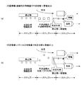
図11は、合流地点におけるアプリケーションの切り替えを説明する図の一例である。なお、すでにアプリケーション切替部231はBSMアプリに切り替えているとする。図11(a)では、壁を静止物と判定していたが、合流車両の合流により静止物を移動物であるという判定に切り替えている。
〔Concrete example〕
FIG. 11 is an example of a diagram illustrating application switching at a junction. It is assumed that the
ステップi
対象物検知装置100は壁を静止物として検知している。また、対象物検知装置100は自車両の位置情報を継続的に取得しているため、合流地点付近を走行していることを検出済である。
Step i
The
ステップii
合流地点の壁がなくなると、レーダー装置11は予測点(又は平滑点)とペアリング可能な観測点を検出しなくなる。この場合、追尾フィルタ223は単に予測点が等速直線運動していると仮定して観測点を補間する。この間に、合流地点に並走走行車が合流する。移動物・静止物判別部232は、観測点が連続して検出されない予測追尾の不連続時間を特徴量にして静止物か移動物かを判定する。
Step ii
When there is no wall at the merge point, the
ステップiii
ステップi及びステップiiの情報から、移動物・静止物判別部232は、静止物と判定していた対象物と移動物と判定する。これにより、警報部23が合流車両に対し警報を出力することができる。
Step iii
From the information of step i and step ii, the moving object / stationary
図11(b)でも同様に、壁を静止物と判定していたが移動物であるという判定に切り替えているが、位置情報と予測点のばらつきから判定を切り替えている。 Similarly in FIG. 11B, although the wall is determined to be a stationary object, it is switched to a determination that it is a moving object, but the determination is switched based on variations in position information and prediction points.
ステップi
図11(a)と同様に、対象物検知装置100は、壁を静止物として検知し、合流地点付近を走行していることを検出済である。
Step i
Similar to FIG. 11A, the
ステップii
合流地点の壁がなくなると、レーダー装置11は観測点を検出するが誤差が大きくなり、予測点のばらつきが大きくなる。この間に、合流地点に並走走行車が合流する。この場合、移動物・静止物判別部232は、予測点の位置情報のばらつきを特徴量にして静止物か移動物かを判定する。
Step ii
If the wall at the merge point disappears, the
ステップiii
ステップi及びステップiiの情報から、移動物・静止物判別部232は、静止物と判定していた対象物と移動物と判定する。これにより、警報部23が合流車両に対し警報を出力することができる。
Step iii
From the information of step i and step ii, the moving object / stationary
図12は、カーブ走行時におけるアプリケーションの切り替えを説明する図の一例である。図12(a)では自車両の後方車両が、レーダー装置11により補足されなくなり、壁が補足されている。アプリケーション切替部231はLCAアプリに切り替えている。
FIG. 12 is an example of a diagram illustrating application switching during curve driving. In FIG. 12A, the vehicle behind the host vehicle is not supplemented by the
ステップi
対象物検知装置100は自車両の位置情報を継続的に取得しているため、カーブ付近を走行していることを検出済である。また、LCAエリアで追尾が開始されたことを記録しておく。
Step i
Since the
ステップii
また、対象物検知装置100は、LCAエリア内の後方車両を検知しているが、カーブ付近なので警報を一時無効にする。車両がカーブ出口に進むことで、対象物は移動物から壁に入れ替わる。しかし、この壁はBSMエリアにて検出されないので警報の対象にならず、また、警報が禁止されているのでLCAによっても警報されない。このため、移動物が静止物に入れ替わった場合に警報を出力することを抑制できる。
Step ii
Moreover, although the target
図12(b)では自車両の後方車両が、自車両と共にカーブを走行している。アプリケーション切替部231はLCAアプリに切り替えている。
In FIG. 12B, the vehicle behind the host vehicle is traveling along a curve together with the host vehicle. The
ステップi
図12(a)と同様である。
Step i
This is the same as FIG.
ステップii
また、対象物検知装置100は、LCAエリア内の後方車両を検知しているが、カーブ付近なので警報を一時無効にする。
Step ii
Moreover, although the target
ステップiii
アプリケーション切替部231はBSMアプリに切り替える。BSMエリアに対象物が検出されているが、LCAエリアから継続して追尾されている対象物なので、移動物・静止物判別部232は移動物であると判定する。これにより、警報部23は警報できる。
Step iii
The
以上説明したように、本実施形態の対象物検知装置100は、現在位置と対象物の過去の位置情報の特徴から、所定の場所における移動物から静止物への切り替わり、移動物から静止物への切り替わりを検出して、警報するか否かを適切に制御することができる。
As described above, the
11 レーダー装置
12 ナビECU
13 運転支援ECU
14 作動デバイス
21 検波部
22 追尾部
23 警報部
100 対象物検知装置
11
13 Driving assistance ECU
DESCRIPTION OF
Claims (5)
対象物の位置情報を記録する位置記録手段と、
位置情報取得手段が取得した自車両の現在の位置が予め定めた場所である場合、前記位置記録手段が記録した同じ対象物の過去の位置情報に基づき、対象物が移動物か否かを判定する判定手段と、
前記判定手段の判定結果に基づき警報手段を制御する警報制御手段と、
を有することを特徴とする対象物検知装置。 An object detection device that detects an object based on radar reflected from the object,
Position recording means for recording position information of the object;
When the current position of the host vehicle acquired by the position information acquisition unit is a predetermined location, it is determined whether the target object is a moving object based on past position information of the same target object recorded by the position recording unit. Determination means to perform,
Alarm control means for controlling the alarm means based on the determination result of the determination means;
The object detection apparatus characterized by having.
前記判定手段は、前記位置記録手段が記録した位置情報に基づき静止物と判定されていた対象物について、位置情報が連続して測定されないこと又は位置情報が所定値以上変動することの少なくとも一方が生じた場合に、対象物が静止物から移動物に切り替わったと判定する、
ことを特徴とする請求項1記載の対象物検知装置。 If the current position of the host vehicle acquired by the position information acquisition means is a merging point,
The determination means has at least one of position information not continuously measured or position information fluctuating by a predetermined value or more with respect to an object that has been determined to be a stationary object based on the position information recorded by the position recording means. When it occurs, it is determined that the object has been switched from a stationary object to a moving object.
The object detection device according to claim 1.
前記位置情報取得手段が取得した自車両の現在の位置がカーブの場合、
前記判定手段は、前記位置記録手段が記録した位置情報が前記第1の範囲に含まれる対象物について移動物か静止物かの判定を保留し、
前記警報制御手段は、前記第1の範囲に移動物が存在しても警報を行わない、
ことを特徴とする請求項1記載の対象物検知装置。 The alarm control means warns a moving object existing in a second range closer to the host vehicle than the first range, and a first operation mode for alarming a moving object existing in the first range. A second operating mode;
When the current position of the host vehicle acquired by the position information acquisition unit is a curve,
The determination unit suspends the determination of whether the position information recorded by the position recording unit is a moving object or a stationary object for an object included in the first range;
The alarm control means does not issue an alarm even if there is a moving object in the first range.
The object detection device according to claim 1.
前記位置記録手段が記録した位置情報に基づき前記第1の範囲で移動物と判定されていた対象物について、現在の位置情報が前記第2の範囲に含まれる場合は対象物が移動物であると判定し、
前記警報制御手段は、前記第2の範囲の対象物に対し警報する、
ことを特徴とする請求項3記載の対象物検知装置。 The determination means includes
For an object that has been determined as a moving object in the first range based on the position information recorded by the position recording means, if the current position information is included in the second range, the object is a moving object. And
The alarm control means warns the object in the second range;
The object detection device according to claim 3.
自車両の位置を検出する位置検出手段と、
対象物の位置情報を記録する位置記録手段と、
前記位置検出手段が取得した自車両の現在の位置が予め定めた場所である場合に、前記位置記録手段が記録した同じ対象物の過去の位置情報に基づき、対象物が移動物か否かを判定する判定手段と、
警報を出力する警報手段と、
前記判定手段の判定結果に基づき前記警報手段を制御する警報制御手段と、
を有することを特徴とする対象物検知装置。 An object detection device that detects an object based on radar reflected from the object,
Position detecting means for detecting the position of the host vehicle;
Position recording means for recording position information of the object;
If the current position of the host vehicle acquired by the position detection means is a predetermined place, whether or not the object is a moving object is determined based on past position information of the same object recorded by the position recording means. Determination means for determining;
An alarm means for outputting an alarm;
Alarm control means for controlling the alarm means based on the determination result of the determination means;
The object detection apparatus characterized by having.
Priority Applications (1)
| Application Number | Priority Date | Filing Date | Title |
|---|---|---|---|
| JP2013188763A JP2015054603A (en) | 2013-09-11 | 2013-09-11 | Object detection device |
Applications Claiming Priority (1)
| Application Number | Priority Date | Filing Date | Title |
|---|---|---|---|
| JP2013188763A JP2015054603A (en) | 2013-09-11 | 2013-09-11 | Object detection device |
Publications (1)
| Publication Number | Publication Date |
|---|---|
| JP2015054603A true JP2015054603A (en) | 2015-03-23 |
Family
ID=52819294
Family Applications (1)
| Application Number | Title | Priority Date | Filing Date |
|---|---|---|---|
| JP2013188763A Pending JP2015054603A (en) | 2013-09-11 | 2013-09-11 | Object detection device |
Country Status (1)
| Country | Link |
|---|---|
| JP (1) | JP2015054603A (en) |
Cited By (3)
| Publication number | Priority date | Publication date | Assignee | Title |
|---|---|---|---|---|
| JP2018066716A (en) * | 2016-10-14 | 2018-04-26 | 国立大学法人金沢大学 | Object tracking device |
| WO2021229704A1 (en) * | 2020-05-13 | 2021-11-18 | 三菱電機株式会社 | Object recognition device, route generation device, parking assistance device, object recognition system, route generation system, and parking assistance system |
| WO2025262850A1 (en) * | 2024-06-19 | 2025-12-26 | Astemo株式会社 | Driving assistance system and driving assistance method |
-
2013
- 2013-09-11 JP JP2013188763A patent/JP2015054603A/en active Pending
Cited By (6)
| Publication number | Priority date | Publication date | Assignee | Title |
|---|---|---|---|---|
| JP2018066716A (en) * | 2016-10-14 | 2018-04-26 | 国立大学法人金沢大学 | Object tracking device |
| WO2021229704A1 (en) * | 2020-05-13 | 2021-11-18 | 三菱電機株式会社 | Object recognition device, route generation device, parking assistance device, object recognition system, route generation system, and parking assistance system |
| JPWO2021229704A1 (en) * | 2020-05-13 | 2021-11-18 | ||
| JP7490054B2 (en) | 2020-05-13 | 2024-05-24 | 三菱電機株式会社 | Object recognition device, path generation device, parking assistance device, object recognition system, path generation system, and parking assistance system |
| US12275394B2 (en) | 2020-05-13 | 2025-04-15 | Mitsubishi Electric Corporation | Object recognition device, path planning device, parking support device, object recognition system, path planning system and parking support system |
| WO2025262850A1 (en) * | 2024-06-19 | 2025-12-26 | Astemo株式会社 | Driving assistance system and driving assistance method |
Similar Documents
| Publication | Publication Date | Title |
|---|---|---|
| JP6318864B2 (en) | Driving assistance device | |
| US10710632B2 (en) | Automatic driving control device | |
| JP4990424B2 (en) | Driving support device | |
| US10302760B2 (en) | Vehicle water detection system | |
| CN105799700B (en) | Avoid collision control system and control method | |
| JP5267570B2 (en) | Driving assistance device | |
| US20150353078A1 (en) | Driving assistance apparatus | |
| JP6323063B2 (en) | Traveling lane identification device, lane change support device, traveling lane identification method | |
| JP6323064B2 (en) | Traveling lane identification device, lane change support device, traveling lane identification method | |
| WO2017042089A1 (en) | Automated detection of hazardous drifting vehicles by vehicle sensors | |
| US11628860B2 (en) | Autonomous driving system that can eliminate a system distrust state of the driver | |
| US11999370B2 (en) | Automated vehicle system | |
| JP2014241115A (en) | Peripheral object detection device | |
| CN111708016A (en) | A vehicle forward collision warning method based on the fusion of millimeter-wave radar and lidar | |
| JP2014227000A (en) | Vehicle control device, method and program | |
| JP2015055541A (en) | Surrounding object detection apparatus | |
| JP2019028841A (en) | Outside alarm system | |
| KR102022539B1 (en) | Lane departure warning system | |
| WO2020137747A1 (en) | Driving assistance apparatus | |
| WO2020084805A1 (en) | Notification device and notification method | |
| JP2015054603A (en) | Object detection device | |
| JP2006024103A (en) | Vehicle travel support device | |
| JP2015072636A (en) | Information processing device | |
| JP7606308B2 (en) | Vehicle moving object detection device | |
| JPH11144198A (en) | Object identifying device for vehicle |