JP2015001411A - Electronic device and charging system - Google Patents
Electronic device and charging system Download PDFInfo
- Publication number
- JP2015001411A JP2015001411A JP2013125156A JP2013125156A JP2015001411A JP 2015001411 A JP2015001411 A JP 2015001411A JP 2013125156 A JP2013125156 A JP 2013125156A JP 2013125156 A JP2013125156 A JP 2013125156A JP 2015001411 A JP2015001411 A JP 2015001411A
- Authority
- JP
- Japan
- Prior art keywords
- power supply
- voltage
- built
- increase
- electronic device
- Prior art date
- Legal status (The legal status is an assumption and is not a legal conclusion. Google has not performed a legal analysis and makes no representation as to the accuracy of the status listed.)
- Pending
Links
- 238000007600 charging Methods 0.000 title claims abstract description 88
- 238000001514 detection method Methods 0.000 claims abstract description 40
- 230000006866 deterioration Effects 0.000 claims description 112
- 238000000034 method Methods 0.000 claims description 74
- 230000008569 process Effects 0.000 claims description 64
- 238000010277 constant-current charging Methods 0.000 claims description 34
- 230000015556 catabolic process Effects 0.000 abstract description 4
- 238000006731 degradation reaction Methods 0.000 abstract description 4
- 230000005855 radiation Effects 0.000 description 32
- 230000004048 modification Effects 0.000 description 28
- 238000012986 modification Methods 0.000 description 28
- 238000003384 imaging method Methods 0.000 description 21
- 230000006870 function Effects 0.000 description 16
- 238000012545 processing Methods 0.000 description 11
- 239000000758 substrate Substances 0.000 description 8
- 239000003990 capacitor Substances 0.000 description 6
- 238000010586 diagram Methods 0.000 description 6
- HBBGRARXTFLTSG-UHFFFAOYSA-N Lithium ion Chemical compound [Li+] HBBGRARXTFLTSG-UHFFFAOYSA-N 0.000 description 5
- 230000009286 beneficial effect Effects 0.000 description 5
- 229910001416 lithium ion Inorganic materials 0.000 description 5
- 230000007246 mechanism Effects 0.000 description 5
- 238000010280 constant potential charging Methods 0.000 description 4
- 230000008859 change Effects 0.000 description 3
- 238000004891 communication Methods 0.000 description 3
- 230000002441 reversible effect Effects 0.000 description 3
- 230000004397 blinking Effects 0.000 description 2
- 230000002596 correlated effect Effects 0.000 description 2
- 230000000875 corresponding effect Effects 0.000 description 2
- 230000007423 decrease Effects 0.000 description 2
- 230000000694 effects Effects 0.000 description 2
- 238000011160 research Methods 0.000 description 2
- 238000005070 sampling Methods 0.000 description 2
- 230000002159 abnormal effect Effects 0.000 description 1
- 230000008901 benefit Effects 0.000 description 1
- 239000003086 colorant Substances 0.000 description 1
- 230000001276 controlling effect Effects 0.000 description 1
- 230000003247 decreasing effect Effects 0.000 description 1
- 238000005516 engineering process Methods 0.000 description 1
- 239000011521 glass Substances 0.000 description 1
- 239000000463 material Substances 0.000 description 1
- 239000011159 matrix material Substances 0.000 description 1
- 230000002265 prevention Effects 0.000 description 1
- 238000002601 radiography Methods 0.000 description 1
- 230000003068 static effect Effects 0.000 description 1
- 230000001360 synchronised effect Effects 0.000 description 1
- 239000010409 thin film Substances 0.000 description 1
- 230000007704 transition Effects 0.000 description 1
Images


Landscapes
- Tests Of Electric Status Of Batteries (AREA)
- Charge And Discharge Circuits For Batteries Or The Like (AREA)
Abstract
Description
本発明は、電子機器および充電システムに係り、特に電子機器の使用中に電子機器の内蔵電源を充電可能な電子機器および充電システムに関する。 The present invention relates to an electronic device and a charging system, and more particularly to an electronic device and a charging system that can charge a built-in power source of the electronic device while the electronic device is being used.
電子機器は、キャパシターやバッテリー、二次電池、蓄電デバイス等からなる内蔵電源を内蔵しているものが多い。そして、このような内蔵電源を充電する際には、例えば内蔵電源に一定の電流を供給して定電流充電を行ったり、或いは、一定の電圧を供給して定電圧充電を行ったり、或いはそれらの充電の仕方を組み合わせて充電が行われるように構成されることも少なくない(例えば特許文献1、2等参照)。
Many electronic devices have a built-in power source including a capacitor, a battery, a secondary battery, a power storage device, and the like. When charging such a built-in power supply, for example, a constant current is supplied to the built-in power supply to perform a constant current charge, or a constant voltage is supplied to perform a constant voltage charge. In many cases, the charging is performed by combining the charging methods (see, for example,
そして、例えば携帯電話等のように、電子機器を充電装置に装填して内蔵電源の充電を行うように構成されている電子機器もあるが、電子機器を外部電源に接続した状態でユーザーが電子機器を使用している間に内蔵電源の充電を行うことができるように構成されている電子機器も少なくない。 Some electronic devices, such as mobile phones, are configured to charge an internal power supply by loading the electronic device into a charging device. However, a user can connect an electronic device with the electronic device connected to an external power supply. Many electronic devices are configured so that the built-in power supply can be charged while the device is being used.
ところで、このような内蔵電源の劣化が進んで内蔵電源から正常な値の電力が出力できなくなると、電子機器の動作が異常になったり、或いは、電子機器が動作しなくなったりする。そこで、内蔵電源を充電している間の時間を利用して、内蔵電源の劣化判定を行う技術が種々開発されている。 By the way, when the deterioration of the built-in power supply progresses and normal power cannot be output from the built-in power supply, the operation of the electronic device becomes abnormal or the electronic device does not work. Therefore, various techniques for determining deterioration of the built-in power supply using the time during which the built-in power supply is charged have been developed.
特許文献3には、例えば内蔵電源に対する定電流充電を行っている間に、充電を途中で一時的に中断する。すると、内蔵電源の電圧は、充電を中断する直前の電圧から少し低下する。これは、充電時に内部抵抗を有する内蔵電源に電流を流すことによって内部抵抗による電圧上昇が生じていたが、電流の供給を一時的に中断したことにより、この内部抵抗による電圧上昇分がなくなったためである。
In
そして、この電圧の変化量を、充電時に流していた電流の値で除算することで、内蔵電源の内部抵抗の値を算出する等し、算出した内部抵抗の値等と内部抵抗値の限界値等とを比較して劣化判定を行うことが記載されている。 Then, the internal resistance value of the internal power supply is calculated by dividing the amount of voltage change by the value of the current flowing during charging, and the calculated internal resistance value and the limit value of the internal resistance value. It is described that the deterioration is determined by comparing with the above.
また、特許文献4には、例えば内蔵電源に対する定電流充電を行う間に、内蔵電源の電圧が所定の電圧値から所定の電圧値まで上昇するのに要する時間を測定したり、時間を横軸にとり内蔵電源の電圧を縦軸にとったばあいの内蔵電源の電圧の上昇の傾きを算出する等して、内蔵電源の劣化判定を行うことが記載されている。
In
そして、これらは、車両に搭載された主電源(すなわちいわゆる車両のバッテリー)の電圧が低下した場合等に電力を出力して、バッテリーの電圧低下分を補う補助電源としての内蔵電源に関する技術として記載されているが、上記の劣化判定は、通常の電子機器の内蔵電源に対する劣化判定法として採用することができる技術である。 These are described as technologies related to a built-in power source as an auxiliary power source that outputs power when the voltage of a main power source (that is, a so-called vehicle battery) mounted on the vehicle decreases, and compensates for the voltage drop of the battery. However, the above-described deterioration determination is a technique that can be employed as a deterioration determination method for a built-in power source of a normal electronic device.
しかしながら、本発明者らの研究によれば、上記のような劣化判定法を、通常の電子機器(例えば後述する放射線画像撮影装置等)に対して採用して内蔵電源の劣化を判定すると、判定処理を行うごと(すなわち内蔵電源に対して充電を行うごと)に、劣化の判定結果が異なる結果になる場合があることが分かってきた。 However, according to the study by the present inventors, when the deterioration determination method as described above is adopted for a normal electronic device (for example, a radiographic imaging apparatus described later), the deterioration of the built-in power supply is determined. It has been found that each time a process is performed (that is, every time the built-in power supply is charged), the deterioration determination result may be different.
すなわち、内蔵電源に対する充電の際に判定処理を行うごとに、判定された内蔵電源の劣化の度合にばらつきが生じるために、内蔵電源の劣化の度合を正確に判定することが難しい場合があることが分かってきた。 In other words, every time the determination process is performed when charging the built-in power supply, the determined degree of deterioration of the built-in power supply varies, so it may be difficult to accurately determine the degree of deterioration of the built-in power supply. I understand.
そして、このように判定された内蔵電源の劣化の度合にばらつきがあると、内蔵電源の劣化が相当進んでいるにもかかわらず、劣化が進んでいないと判定して内蔵電源を使い続けてしまい、内蔵電源から正常な値の電力が出力できなくなってしまったり、或いは、逆に、内蔵電源の劣化があまり進んでいないにもかかわらず、劣化が進んでいると判定してしまい、まだ使える内蔵電源を交換する等して廃棄してしまう等の問題が生じ得る。 If the degree of deterioration of the internal power source determined in this way varies, the internal power source will continue to be used by determining that the deterioration has not progressed even though the internal power source has deteriorated considerably. The built-in power supply can no longer output normal power, or conversely, the built-in power supply has not progressed much, but it is determined that the deterioration has progressed, and the built-in power supply is still usable. There may be a problem that the power supply is replaced and discarded.
本発明は、上記の点を鑑みてなされたものであり、電子機器の内蔵電源の劣化度合を的確に推定することが可能な電子機器および充電システムを提供することを目的とする。 The present invention has been made in view of the above points, and an object thereof is to provide an electronic device and a charging system that can accurately estimate the degree of deterioration of a built-in power source of the electronic device.
前記の問題を解決するために、本発明の電子機器は、
充電可能な内蔵電源と、
外部電源からの電力の供給を受けて前記内蔵電源に対する充電を行う充電回路と、
前記内蔵電源の電圧を検出する電圧検出回路と、
前記内蔵電源の劣化度合を推定する推定回路と、
を備え、
前記推定回路は、
前記充電回路による前記内蔵電源に対する定電流充電が行われている際に、
初期状態において制御部が各機能部を制御して前記内蔵電源から放電される負荷電流が一定になる状態を形成させた状態と同じ状態で制御部に各機能部を制御させて、前記内蔵電源から放電される負荷電流が一定になる状態を形成させ、
その状態の下で所定時間の間に前記電圧検出回路が検出する前記内蔵電源の電圧の増加分を算出し、算出した前記電圧の増加分と、予め記憶されている前記初期状態における前記電圧の増加分とを比較して前記内蔵電源の劣化度合を推定することを特徴とする。
In order to solve the above problem, the electronic device of the present invention
Rechargeable built-in power supply,
A charging circuit that receives power from an external power source and charges the internal power source;
A voltage detection circuit for detecting the voltage of the internal power supply;
An estimation circuit for estimating the degree of deterioration of the built-in power supply;
With
The estimation circuit includes:
When constant current charging is performed on the built-in power supply by the charging circuit,
In the initial state, the control unit controls each function unit to cause the control unit to control each function unit in the same state as the state where the load current discharged from the built-in power source becomes constant, and the built-in power source Form a state in which the load current discharged from becomes constant,
Under this state, an increase in the voltage of the built-in power supply detected by the voltage detection circuit during a predetermined time is calculated, and the calculated increase in the voltage and the voltage in the initial state stored in advance are calculated. The degree of deterioration of the built-in power supply is estimated by comparing with the increase.
また、本発明の充電システムは、
充電可能な内蔵電源と、
外部電源からの電力の供給を受けて前記内蔵電源に対する充電を行う充電回路と、
前記内蔵電源の電圧を検出する電圧検出回路と、
を備える電子機器と、
前記内蔵電源の劣化度合を推定する推定装置と、
を備え、
前記電子機器は、
前記充電回路による前記内蔵電源に対する定電流充電が行われている際に、
初期状態において制御部が各機能部を制御して前記内蔵電源から放電される負荷電流が一定になる状態を形成させた状態と同じ状態で制御部に各機能部を制御させて、前記内蔵電源から放電される負荷電流が一定になる状態を形成させ、
その状態の下で所定時間の間に前記電圧検出回路が検出する前記内蔵電源の電圧の増加分を算出し、算出した前記電圧の増加分を前記推定装置に送信し、
前記推定装置は、前記電子機器から送信されてきた前記電圧の増加分と、予め記憶されている前記初期状態における前記電圧の増加分とを比較して前記電子機器の前記内蔵電源の劣化度合を推定することを特徴とする。
The charging system of the present invention is
Rechargeable built-in power supply,
A charging circuit that receives power from an external power source and charges the internal power source;
A voltage detection circuit for detecting the voltage of the internal power supply;
An electronic device comprising:
An estimation device for estimating the degree of deterioration of the internal power supply;
With
The electronic device is
When constant current charging is performed on the built-in power supply by the charging circuit,
In the initial state, the control unit controls each function unit to cause the control unit to control each function unit in the same state as the state where the load current discharged from the built-in power source becomes constant, and the built-in power source Form a state in which the load current discharged from becomes constant,
Under the state, the increase in the voltage of the built-in power supply detected by the voltage detection circuit during a predetermined time is calculated, and the calculated increase in the voltage is transmitted to the estimation device,
The estimation device compares the increase in the voltage transmitted from the electronic device with the increase in the voltage in the initial state stored in advance to determine the degree of deterioration of the built-in power source of the electronic device. It is characterized by estimating.
本発明のような方式の電子機器および充電システムによれば、内蔵電源に対する定電流充電が行われている際に、電子機器の制御部に電子機器の各機能部を制御させて内蔵電源から放電される負荷電流が一定になる状態を形成させる。その際、電子機器の工場出荷時等の初期状態において、制御部が各機能部を制御して負荷電流が一定になる状態を形成させた状態と同じ状態で制御部に各機能部を制御させて、負荷電流が一定になる状態を形成させる。 According to the electronic device and the charging system of the system as in the present invention, when constant current charging is performed on the built-in power source, the control unit of the electronic device controls each function unit of the electronic device to discharge from the built-in power source. A state in which the applied load current is constant. At that time, in the initial state such as when the electronic device is shipped from the factory, the control unit controls each function unit in the same state as that in which the control unit controls each function unit to form a state in which the load current is constant. Thus, a state in which the load current becomes constant is formed.
そのため、内蔵電源から放電され一定になった際の負荷電流の値が、初期状態において内蔵電源から放電され一定になった際の負荷電流の値と同じ値になり、内蔵電源内を流れる電流が、初期状態の際も、その後の電子機器の内蔵電源の劣化度合の推定処理を行う際も、同じ電流値になる。 Therefore, the value of the load current when the internal power supply is discharged and becomes constant becomes the same value as the load current when the internal power supply is discharged and becomes constant in the initial state, and the current flowing through the internal power supply In the initial state, the same current value is obtained when estimating the degree of deterioration of the built-in power source of the electronic device thereafter.
そのため、内蔵電源の劣化度合の推定処理において算出した内蔵電源の電圧の増加分と、予め記憶されている初期状態における内蔵電源の電圧の増加分とを比較することで、内蔵電源の劣化度合を的確に精度良く推定することが可能となる。 Therefore, the degree of deterioration of the internal power supply can be determined by comparing the increase in the internal power supply voltage calculated in the estimation process of the internal power supply deterioration with the increase in the internal power supply voltage in the initial state stored in advance. It becomes possible to estimate accurately and accurately.
以下、本発明に係る電子機器および充電システムの実施の形態について、図面を参照して説明する。 Embodiments of an electronic device and a charging system according to the present invention will be described below with reference to the drawings.
なお、以下では、電子機器が放射線画像撮影装置(Flat Panel Detector:FPD)である場合について説明するが、本発明は、この形態に限定されない。 In the following, a case where the electronic device is a radiographic imaging device (Flat Panel Detector: FPD) will be described, but the present invention is not limited to this mode.
[第1の実施の形態]
[電子機器の例としての放射線画像撮影装置の構成例について]
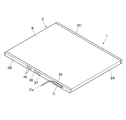
以下、本発明の第1の実施形態に係る電子機器の例として、放射線画像撮影装置1の構成例について簡単に説明する。図1は、放射線画像撮影装置の外観を示す斜視図であり、図2は、図1のX−X線に沿う断面図である。
[First Embodiment]
[Configuration example of radiation imaging apparatus as an example of electronic equipment]
Hereinafter, a configuration example of the radiation
放射線画像撮影装置1は、図1や図2に示すように、筐体状のハウジング2内にシンチレーター3や基板4等で構成されるセンサーパネルSPが収納されて構成されている。本実施形態では、筐体2は、放射線入射面Rを有する中空の角筒状のハウジング本体部2Aの両側の開口部を蓋部材2B、2Cで閉塞することで形成されている。
As shown in FIGS. 1 and 2, the radiation
図1に示すように、筐体2の一方側の蓋部材2Bには、電源スイッチ37や切替スイッチ38、コネクター39、内蔵電源24(図2や後述する図4参照)の状態や放射線画像撮影装置1の稼働状態等を表示するLED等で構成されたインジケーター40等が配置されている。
As shown in FIG. 1, the
なお、後述するように、本実施形態では、電子機器としての放射線画像撮影装置1は、図3に示すように、コネクター39に、ケーブルCaの先端に設けられたコネクターCを接続し、図示しない外部電源から電力を供給して内蔵電源24の充電が行われるようになっている。なお、図示を省略するが、放射線画像撮影装置1等の電子機器を、クレードル等の充電装置に装填して充電する場合にも本発明を適用することが可能である。
As will be described later, in this embodiment, the
また、図示を省略するが、本実施形態では、筐体2の反対側の蓋部材2Cに、放射線画像撮影装置1が外部装置と信号等の送受信を無線方式で行うための図示しないアンテナ装置が、例えば蓋部材2Cに埋め込まれるようにして設けられている。
Although not shown, in this embodiment, an antenna device (not shown) is provided on the
図2に示すように、筐体2の内部には、基板4の下方側に図示しない鉛の薄板等を介して基台31が配置され、基台31には、電子部品32等が配設されたPCB基板33や内蔵電源24等が取り付けられている。また、基板4やシンチレーター3の放射線入射面Rには、それらを保護するためのガラス基板34が配設されており、センサーパネルSPと筐体2の側面との間に緩衝材35が設けられている。
As shown in FIG. 2, a
図示を省略するが、基板4の検出部P上には、フォトダイオード等からなる複数の放射線検出素子7が二次元状(マトリクス状)に配列されており、各放射線検出素子7にスイッチ手段としての薄膜トランジスター(Thin Film Transistor。以下、TFTという。)8や走査線5、信号線6、バイアス線9等が接続されている。また、シンチレーター3が、基板4の検出部Pに対向するように設けられるようになっている。
Although not shown, a plurality of
放射線画像撮影装置1の回路構成を、図4に示すブロック図を用いて説明する。本実施形態では、複数の放射線検出素子7が基板4上に二次元状に配列されて検出部Pが形成されている。また、各放射線検出素子7の第2電極7bにはそれぞれバイアス線9が接続されており、各バイアス線9は結線10に接続されてバイアス電源14に接続されている。そして、結線10および各バイアス線9を介して各放射線検出素子7の第2電極7bにそれぞれバイアス電源14から逆バイアス電圧が印加されるようになっている。
The circuit configuration of the radiation
走査駆動手段15では、電源回路15aからゲートドライバー15bに配線15cを介してオン電圧やオフ電圧が供給され、ゲートドライバー15bで走査線5の各ラインL1〜Lxに印加する電圧をオン電圧とオフ電圧との間で切り替えて、各TFT8のオン状態とオフ状態とを切り替えることで、各放射線検出素子7からの画像データの読み出し処理等を行うようになっている。
In the scanning driving means 15, an ON voltage or an OFF voltage is supplied from the
各信号線6は、読み出しIC16内に形成された各読み出し回路17にそれぞれ接続されており、読み出し回路17は、増幅回路18と相関二重サンプリング回路19(図4ではCDSと記載されている。)等で構成されている。読み出しIC16内には、さらに、アナログマルチプレクサー21と、A/D変換器20とが設けられている。
Each
そして、例えば、各放射線検出素子7からの画像データの読み出し処理の際には、ゲートドライバー15bからオン電圧が印加された走査線5に接続されているTFT8がオン状態になり、オン状態になったTFT8に接続されている放射線検出素子7から信号線6に電荷が放出され、放出された電荷が読み出し回路17の増幅回路18で電荷電圧変換される。
Then, for example, in the process of reading the image data from each
そして、増幅回路18の出力側に設けられた相関二重サンプリング回路19で、放射線検出素子7から電荷が放出される前後の増幅回路18からの出力値の差分を算出し、算出した差分をアナログ値の画像データとして出力する。そして、出力されたアナログ値の画像データが、アナログマルチプレクサー21を介して順次A/D変換器20に送信され、A/D変換器20で順次デジタル値の画像データに変換されて出力され、記憶手段23に順次保存される。このようにして、各放射線検出素子7からの画像データの読み出し処理が順次行われる。
Then, the correlated
制御部22は、図示しないCPU(Central Processing Unit)やROM(Read Only Memory)、RAM(Random Access Memory)、入出力インターフェース等がバスに接続されたマイクロコンピュータや、FPGA(Field Programmable Gate Array)等により構成されている。そして、制御部22は、放射線画像撮影装置1の走査駆動手段15や読み出し回路17、バイアス電源14等の各機能部の動作等を制御するようになっている。
The
また、制御部22には、SRAM(Static RAM)やSDRAM(Synchronous DRAM)等で構成される記憶手段23が接続されている。また、図4では図示を省略するが、本実施形態では、制御部22には、前述した電源スイッチ37や切替スイッチ38、コネクター39、インジケーター40(図1参照)等やアンテナ装置等も接続されている。
The
また、制御部22には、制御部22や走査駆動手段15、読み出し回路17、バイアス電源14等の各機能部に電力を供給するための内蔵電源24が接続されている。本実施形態では、内蔵電源24として、リチウムイオンキャパシター(LiC)が用いられているが、本発明はこれに限定されず、充電可能な内蔵電源であれば、電気二重層キャパシター等の蓄電デバイスやリチウムイオンバッテリー等のバッテリーや二次電池等であってもよい。
The
[電子機器の内蔵電源の充電にかかわる構成等について]
次に、本実施形態に係る電子機器(放射線画像撮影装置1)の推定回路における内蔵電源24の劣化度合の推定処理について説明する前に、上記の放射線画像撮影装置1等の電子機器の内蔵電源24の充電にかかわる構成等について説明する。なお、以下では、放射線画像撮影装置1等の電子機器を電子機器1として一般的な形で説明する。
[About the configuration related to charging the built-in power supply of electronic devices]
Next, before describing the estimation process of the degree of deterioration of the built-in
図5は、電子機器1の内蔵電源24の充電にかかわる構成等を説明するブロック図である。なお、図5や後述する図10では、図3に示したように、電子機器1のコネクター39にコネクターCが接続され、ケーブルCaを介して外部電源(図5では「AC」と記載)から電力が供給される場合が示されている。
FIG. 5 is a block diagram illustrating a configuration related to charging of the built-in
前述したように、電子機器1内では、内蔵電源24と制御部22等の各機能部とが電気的に接続されている。なお、図5では、制御部22以外の走査駆動手段15、読み出し回路17、バイアス電源14(図4参照)等の各機能部が、センサーパネルSPとしてまとめて記載されている。そして、内蔵電源24から制御部22等の各機能部に電力が供給されるが、この内蔵電源24からの電力の供給が、内蔵電源24の放電に相当し、また、その際に内蔵電源24から各機能部に供給される電流が、負荷電流ということになる。
As described above, in the
コネクター39から内蔵電源24に至る充電用の電力供給経路30上には、内蔵電源24の充電を行うための充電回路25が設けられている。なお、図示を省略するが、充電回路25とコネクター39との間に、例えば充電回路25側からコネクター39側に電流が逆流しないようにするための逆流防止回路等を設けることも可能である。
A charging
そして、充電回路25は、コネクターC、39を介して外部電源から充電用の電力が供給されてもすぐには内蔵電源24の充電を開始せず、電子機器1の制御部22から充電開始を指示する制御信号を受信した時点で初めて内蔵電源24に電力を供給して内蔵電源24の充電を行うようになっている。
The charging
本実施形態では、充電回路25は、内蔵電源24を充電する際に、例えば図6(A)、(B)に示すように、内蔵電源24の電圧Vが設定された電圧値V1に達するまでは、内蔵電源24に所定の電流値Isの定電流を供給して定電流充電を行う。そして、内蔵電源24の電圧Vが設定された電圧値V1に達した後は、今度は、内蔵電源24に目標電圧V2の定電圧を供給して定電圧充電を行うようにして、内蔵電源24の充電を行うようになっている。
In the present embodiment, when the charging
そして、充電回路25は、定電圧充電の際に内蔵電源24に供給する電流の値が充電終了値Ieまで低下した時点で、内蔵電源24に対する充電を終了するように構成されている。
The charging
しかし、充電回路25は、このように、定電流充電の後に定電圧充電を行うように構成されているものに限定されず、少なくとも定電流充電を行うものであればよい。そして、本発明は、充電回路25が内蔵電源24を充電する際に少なくとも定電流充電を行う期間を有するものであれば、どのような電子機器1にも適用することが可能である。
However, the charging
本実施形態では、電子機器1は、内蔵電源24の充電にかかわる構成として、さらに、電圧検出回路26と推定回路27とを備えている。なお、図5では、電圧検出回路26と推定回路27が電子機器1の制御部22とは別々に記載されているが、それらのうちのいずれか一方或いは両方を制御部22内に構築するように構成することも可能である。すなわち、電子機器1の制御部22が、電圧検出回路26や推定回路27として機能するように構成することも可能である。
In the present embodiment, the
電圧検出回路26は、内蔵電源24の電圧Vを検出するようになっている。なお、上記の充電回路25の内部にも内蔵電源24の電圧Vを検出する回路が形成されているため、その回路を電圧検出回路26とし、その回路が検出した内蔵電源24の電圧Vの情報を用いるように構成することも可能である。
The
[電子機器の推定回路における内蔵電源の劣化度合の推定処理について]
次に、電子機器1の推定回路27における内蔵電源24の劣化度合の推定処理について説明する。また、本実施形態に係る電子機器1の作用についてもあわせて説明する。
[Estimation of deterioration level of built-in power supply in electronic device estimation circuit]
Next, processing for estimating the degree of deterioration of the built-in
前述した特許文献3や特許文献4に記載された技術と同様に、本実施形態においても、推定回路27は、充電回路25が内蔵電源24に対して定電流充電(図6参照)を行っている間に電圧検出回路26が検出した内蔵電源24の電圧Vに基づいて、内蔵電源24の劣化度合を推定するように構成されている。
Similar to the techniques described in
[従来の内蔵電源の劣化度合の推定処理の問題点について]
しかし、単に内蔵電源24の電圧Vに基づいて内蔵電源24の劣化度合を推定すると、前述したように、推定結果にばらつきが生じてしまう場合がある。そして、本発明者らの研究では、例えば図3に示したように、電子機器1のコネクター39にケーブルCaを接続する等して、外部電源から電力を供給した状態で電子機器1の使用中に内蔵電源24を充電する場合に、特に上記の推定結果のばらつきが発生し易くなることが分かってきた。
[Problems of estimation processing of deterioration level of conventional built-in power supply]
However, if the degree of deterioration of the built-in
このような現象が生じる原因について本発明者らが研究を重ねた結果、電子機器1の内蔵電源24に対して定電流充電を行う際に、内蔵電源24から電子機器1の制御部22等の各機能部に供給される電流すなわち負荷電流Iloadが必ずしも一定でないことが、上記の現象が生じる1つの原因であることが分かってきた。
As a result of the present inventors' research on the cause of such a phenomenon, when constant current charging is performed on the built-in
具体的に説明すると、電子機器1が稼動中である場合には、内蔵電源24から電子機器1の制御部22等の各機能部(すなわち例えば走査駆動手段15、読み出し回路17、バイアス電源14等(図4参照))に、各機能部が必要とする量の電力が各機能部に必要とされるタイミングで供給される。そのため、例えば図7に示すように、内蔵電源24の負荷電流Iloadが時間ごとに変化する状態になる。
More specifically, when the
なお、図7において、負荷電流Iloadが一定の時間間隔でパルス状に大きな値になっているのは、例えば、電子機器1としての放射線画像撮影装置1(図1等参照)が撮影室等に持ち込まれて放射線撮影に使用される際に、放射線画像撮影装置1の図示しないアンテナ装置が、撮影室の図示しないアクセスポイントとの間で定期的に信号のやり取りを行っているためである。
In FIG. 7, the load current Iload has a large value in a pulse shape at a constant time interval. For example, the radiographic image capturing apparatus 1 (see FIG. 1 or the like) as the
そして、上記のように内蔵電源24に定電流充電を行って、充電回路25(図5参照)から一定値Is(図6(B)参照)の電流Iを内蔵電源24に供給しても、内蔵電源24が放電される負荷電流Iload(図7参照)の値が時間的に一定の値にならないため、内蔵電源24の電圧Vの上昇率が一定にならない。
Then, even if constant current charging is performed on the built-in
すなわち、充電により内蔵電源24に入ってくる電流Iが一定(すなわち図6(B)の場合はIs)であっても、放電により負荷電流Iloadとして内蔵電源24から出て行く電流が多ければ、内蔵電源24に蓄えられる電力は少なくなり、内蔵電源24の電圧Vの上昇率は小さくなる。また、放電により負荷電流Iloadとして内蔵電源24から出て行く電流が少なければ、内蔵電源24に蓄えられる電力が多くなり、内蔵電源24の電圧Vの上昇率は大きくなる。
That is, even if the current I entering the built-in
そのため、上記のように内蔵電源24に定電流充電を行って充電回路25から一定値Isの電流Iを内蔵電源24に供給しても、内蔵電源24が放電される負荷電流Iloadの値が時間的に一定の値にならなければ、内蔵電源24の電圧Vの上昇率も一定にならない。
Therefore, even if constant current charging is performed on the built-in
なお、図6(A)では、定電流充電を行っている間、内蔵電源24の電圧Vが一定の上昇率で上昇するように記載されているが、実際には、負荷電流Iloadが時間的に増加したり減少したりするため(図7参照)、内蔵電源24の電圧Vの上昇率は一定にはならず、実際には、電圧Vの上昇率が大きくなったり小さくなったりしている。すなわち、図6(A)の定電流充電時のグラフの傾きは実際には一定ではなく、大きくなったり小さくなったりしている。
In FIG. 6A, the voltage V of the built-in
そして、上記のように、負荷電流Iloadが時間的に変化することで内蔵電源24の電圧Vの上昇率が一定にならないため、例えば前述した特許文献3に記載されているように、内蔵電源24に対する定電流充電を行っている間に、充電を途中で一時的に中断した際に検出される内蔵電源24の電圧Vの変化量が、内蔵電源24の容量や内部抵抗の値等が同じであっても必ずしも一定の値にならない。
As described above, since the rate of increase of the voltage V of the built-in
また、負荷電流Iloadが時間的に変化することで内蔵電源24の電圧Vの上昇率が一定にならないため、例えば前述した特許文献4に記載されているように、内蔵電源24に対する定電流充電を行う間に、内蔵電源24の電圧Vが所定の電圧値から所定の電圧値まで上昇するのに要する時間が、内蔵電源24の状態が同じであっても必ずしも一定の時間にならない。
Further, since the rate of increase of the voltage V of the built-in
そして、このように、内蔵電源24の状態が仮に全く同じであっても、負荷電流Iloadが時間的に変化することで内蔵電源24の電圧Vの上昇率が一定にならず、内蔵電源24の電圧Vの変化量(特許文献3の場合)や時間(特許文献4の場合)が必ずしも一定にならないため、それに基づいて推定される内蔵電源24の劣化度合の推定結果が同じにならずにばらつきが生じてしまうのである。
As described above, even if the state of the built-in
[本発明に特有の構成等について]
そこで、上記のように、本実施形態に係る電子機器1においても、推定回路27(図5参照)は、内蔵電源24の定電流充電中に、電圧検出回路26が検出した内蔵電源24の電圧Vに基づいて内蔵電源24の劣化度合の推定処理を行うように構成されているが、その際、図8に示すように、内蔵電源24の負荷電流Iloadが一定になる状態(図中Aで示される期間参照)にしたうえで、電圧検出回路26に内蔵電源24の電圧Vを検出させるようになっている。
[Configurations Specific to the Present Invention]
Therefore, as described above, also in the
すなわち、推定回路27は、電子機器1の制御部22(図4や図5参照)に電子機器1の各機能部を制御させて内蔵電源24から放電される負荷電流Iloadが一定になる状態を形成させる。
That is, the
この場合、例えば、制御部22は、電子機器1の走査駆動手段15、読み出し回路17、バイアス電源14等の各機能部がそれぞれ行っている動作を停止させるように制御し、そのうえで各機能部にそれぞれ予め設定した一定の電流を供給する状態にして、内蔵電源24から放電される負荷電流Iloadが一定になる状態を形成する。
In this case, for example, the
そして、本実施形態では、推定回路27は、その状態の下で、図8に示すように、所定時間Δtの間に電圧検出回路26が検出する内蔵電源24の電圧Vの増加分ΔVを算出する。すなわち、負荷電流Iloadを一定にした時点から所定時間Δtが経過する前後に電圧検出回路26が検出した内蔵電源24の電圧Vの差分を、内蔵電源24の電圧Vの増加分ΔVとして算出する。
In this embodiment, the
一方、推定回路27は、例えば電子機器1の工場出荷時等の初期状態で、予め上記と同じ条件で内蔵電源24の電圧Vの増加分ΔV0を算出しておくようになっており、この初期状態における内蔵電源24の電圧Vの増加分ΔV0をメモリー28(図5参照)内に保持している。
On the other hand, the
そして、推定回路27は、今回の内蔵電源24の劣化度合の推定処理で上記のようにして算出した内蔵電源24の電圧Vの増加分ΔVと、予め記憶されている初期状態における電圧Vの増加分ΔV0とを比較して内蔵電源24の劣化度合を推定するようになっている。
Then, the
なお、上記の説明では、内蔵電源24の劣化度合の推定処理で内蔵電源24の電圧Vの増加分ΔVを算出したのと同じ条件で、初期状態において内蔵電源24の電圧Vの増加分ΔV0を算出しておくように記載したが、実際には、その逆で、初期状態において内蔵電源24の電圧Vの増加分ΔV0を算出したのと同じ条件で、その後の内蔵電源24の劣化度合の推定処理において内蔵電源24の電圧Vの増加分ΔVを算出するように構成される。
In the above description, the increase ΔV 0 of the voltage V of the built-in
すなわち、電子機器1の工場出荷時等の初期状態において、内蔵電源24から放電される負荷電流Iloadが一定になる状態を形成するために、電子機器1の制御部22が、各機能部の動作を停止させて、各機能部にそれぞれ予め設定した一定の電流を供給した状態と同じ状態を、その後の電子機器1の内蔵電源24の劣化度合の推定処理を行う際に、電子機器1の制御部22が再現するようになっている。
That is, in order to form a state in which the load current Iload discharged from the built-in
このように構成すると、電子機器1の内蔵電源24の劣化度合の推定処理を行う際に、内蔵電源24から放電され一定になった際の負荷電流Iloadの値が、初期状態において内蔵電源24から放電され一定になった際の負荷電流Iloadの値と同じ値になる。
With this configuration, when the process of estimating the degree of deterioration of the built-in
そのため、初期状態においても、また、電子機器1の内蔵電源24の劣化度合の推定処理を行う際も、定電流充電により内蔵電源24に入ってくる電流Iは同じ値Is(図6(B)参照)であり、放電により負荷電流Iloadとして内蔵電源24から出て行く電流の値も同じ値になる。
For this reason, even in the initial state and when estimating the degree of deterioration of the built-in
そのため、このような状態で内蔵電源24内を流れる電流(すなわち入ってくる電流Isと出て行く電流Iloadとの差分)は、初期状態においても、また、電子機器1の内蔵電源24の劣化度合の推定処理を行う際も、同じ電流値になる。
Therefore, the current flowing in the
そして、例えば、初期状態と、電子機器1の内蔵電源24の劣化度合の推定処理時で、内蔵電源24の容量Cの大きさが同じであれば、
ΔV=(Is−Iload)・Δt/C …(1)
の関係から、所定時間Δtの間の内蔵電源24の電圧Vの増加分ΔVは同じ大きさになる。
For example, if the capacity C of the built-in
ΔV = (Is−Iload) · Δt / C (1)
Therefore, the increase ΔV of the voltage V of the built-in
また、内蔵電源24が劣化して容量Cの大きさが変われば、所定時間Δtの間の内蔵電源24の電圧Vの上昇分ΔVは、初期状態と、電子機器1の内蔵電源24の劣化度合の推定処理時で、異なる大きさになる。
Further, if the built-in
そのため、本実施形態のように、内蔵電源24の劣化度合の推定処理において算出した内蔵電源24の電圧Vの増加分ΔVと、予め記憶されている初期状態における電圧Vの増加分ΔV0とを比較することで、内蔵電源24の劣化度合を推定することが可能となるのである。
Therefore, as in the present embodiment, the increment ΔV of the voltage V of the built-in
内蔵電源24が劣化すると、通常、内蔵電源24の容量Cが小さくなるため、上記のように内蔵電源24内を流れる電流の大きさが初期状態と推定処理時で同じ電流値であれば、内蔵電源24が劣化するほど、算出した内蔵電源24の電圧Vの増加分ΔVが大きくなり、初期状態における増加分ΔV0との乖離が大きくなる。
When the built-in
そのため、本実施形態のように、算出した内蔵電源24の電圧Vの増加分ΔVと、予め記憶されている初期状態における電圧Vの増加分ΔV0とを比較することで、内蔵電源24の劣化度合を的確に推定することが可能となる。
Therefore, as in this embodiment, the increment [Delta] V of the voltage V of the calculated
[変形例1]
なお、本実施形態のように、推定回路27が、算出した内蔵電源24の電圧Vの増加分ΔVと、初期状態における電圧Vの増加分ΔV0とを比較するように構成する代わりに、或いはそれと並行して、算出した内蔵電源24の電圧Vの増加分ΔVの、初期状態における電圧Vの増加分ΔV0に対する比ΔV/ΔV0を算出し、算出した比ΔV/ΔV0に基づいて内蔵電源24の劣化度合を推定するように構成することも可能である。
[Modification 1]
Instead of the configuration in which the
上記のように、内蔵電源24が劣化するほど、算出した内蔵電源24の電圧Vの増加分ΔVが大きくなるため、初期状態における増加分ΔV0と比ΔV/ΔV0は、内蔵電源24の劣化が進むほど大きくなっていく。そのため、比ΔV/ΔV0を算出することで、内蔵電源24の劣化度合を数値(すなわちΔV/ΔV0)として評価することが可能となる。
As described above, as the built-in
[変形例2]
また、上記の電子機器1の内蔵電源24の劣化度合の推定処理は、内蔵電源24に対する定電流充電が行われている間に行われる必要がある。すなわち、定電流充電を行っている間に推定処理(すなわち内蔵電源24の電圧Vの増加分ΔVの算出処理)を開始したが、その途中で、図6(A)に示したように、充電の仕方が定電圧充電に切り替わる等して定電流充電が終わってしまうと、内蔵電源24の電圧Vの増加分ΔVを算出することができなくなり、推定処理を行うことができなくなる。
[Modification 2]
In addition, the estimation process of the deterioration degree of the built-in
そこで、例えば、定電流充電を行っているが、内蔵電源24の電圧Vがまだ十分に低く、上記のように、所定時間Δtの間、内蔵電源24から放電される負荷電流Iloadを一定にしても(図8参照)、その所定時間Δtが経過する間に定電流充電が終わることがないと判断される場合に、推定回路27による上記の推定処理を行うように構成することが可能である。
Thus, for example, constant current charging is performed, but the voltage V of the built-in
すなわち、推定回路27は、電圧検出回路26が検出した内蔵電源24の電圧Vに基づいて、充電回路25(図5参照)による内蔵電源24に対する定電流充電が、少なくとも上記の所定時間Δtの間継続するか否かを判定し、定電流充電が少なくとも所定時間Δtの間継続すると判定した場合に、上記の内蔵電源24の劣化度合の推定処理を行うように構成すること可能である。
That is, the
このように構成すれば、内蔵電源24の劣化度合の推定処理を行っている間に定電流充電が終了してしまうことを的確に防止することが可能となり、内蔵電源24の劣化度合の推定処理を的確に行うことが可能となる。
If comprised in this way, it will become possible to prevent reliably that constant current charge will be complete | finished while performing the estimation process of the deterioration degree of the
[変形例3]
また、上記のように、外部電源から電力を供給した状態(図3や図5参照)でユーザーが電子機器1を使用している間に内蔵電源24の充電を行う際、内蔵電源24の劣化度合の推定処理を行っている最中にユーザーによる電子機器1に対する操作があった場合には、通常、内蔵電源24の劣化度合の推定処理よりも、ユーザーの操作の方が優先されるように構成される。
[Modification 3]
In addition, as described above, when charging the
このように、ユーザーが電子機器1を使用する場合には、基本的に、内蔵電源24の劣化度合の推定処理を行うことができない。
As described above, when the user uses the
そこで、推定回路27は、内蔵電源24の定電流充電時に、所定期間(上記の所定時間Δtではない。)の間、ユーザーによる電子機器1に対する操作が行われていない場合に、上記の内蔵電源24の劣化度合の推定処理を行うように構成することが可能である。また、ユーザーから指示があった場合に、上記の内蔵電源24の劣化度合の推定処理を行うように構成することも可能である。
Therefore, the
このように構成すれば、ユーザーが電子機器1を使っていない状態、或いは、推定処理のために電子機器1が使えなくなることをユーザーが認識している状態で、上記の内蔵電源24の劣化度合の推定処理を行うことが可能となる。
With this configuration, the degree of deterioration of the built-in
そのため、内蔵電源24の劣化度合の推定処理を行っている最中にユーザーによる電子機器1に対する操作がある可能性が低い状態、或いはその可能性がない状態で内蔵電源24の劣化度合の推定処理を行うことが可能となり、内蔵電源24の劣化度合の推定処理を的確に行うことが可能となる。
Therefore, the process of estimating the degree of deterioration of the built-in
[変形例4−1]
なお、上記の実施形態では、初期状態においても、また、実際に内蔵電源24の劣化度合の推定処理を行う場合においても、内蔵電源24から放電される負荷電流Iloadを一定にする所定時間Δt(図8参照)を同じ時間とすることを前提として説明した。
[Modification 4-1]
In the above-described embodiment, the predetermined time Δt () in which the load current Iload discharged from the built-in
しかし、実際に内蔵電源24の劣化度合の推定処理を行う場合において、内蔵電源24から放電される負荷電流Iloadを一定にする所定時間Δtを、初期状態における所定時間Δt0と同じ時間だけとれない場合もあり得る。
However, when the estimation process of the deterioration degree of the built-in
また、内蔵電源24の劣化度合の推定処理の際に、上記の[変形例2]で述べたように定電流充電が推定処理の途中で終わってしまったり、或いは、上記の[変形例3]で述べたように内蔵電源24の劣化度合の推定処理を行っている最中にユーザーによる電子機器1に対する操作があった場合、推定処理が中断されるまでの所定時間Δtが、推定処理を精度良く行うために十分な時間であれば、その所定時間Δtにおける電圧Vの増加分ΔVを用いて内蔵電源24の劣化度合の推定処理を行うことも可能である。
In addition, in the process of estimating the degree of deterioration of the built-in
そこで、内蔵電源24の劣化度合の推定処理における上記の所定時間Δt(図8参照)を、初期状態における上記の所定時間Δt0とは異なる時間とするように構成することも可能である。なお、この場合、推定回路27は、前述した初期状態における内蔵電源24の電圧Vの増加分ΔV0の他に、初期状態における上記の所定時間Δt0もメモリー28内に保持しておくように構成される。
Therefore, the predetermined time Δt (see FIG. 8) in the estimation process of the deterioration degree of the built-in
そして、本実施形態のように、推定回路27は、算出した内蔵電源24の電圧Vの増加分ΔVと、初期状態における電圧Vの増加分ΔV0とを用いて内蔵電源24の劣化度合の推定処理を行う代わりに、算出した内蔵電源24の電圧Vの増加分ΔV、当該電圧Vを検出した際の所定時間Δt、初期状態における電圧Vの増加分ΔV0、および初期状態における所定時間Δt0を用いて内蔵電源24の劣化度合の推定処理を行うように構成することが可能である。
Then, as in the present embodiment, the
具体的には、例えば、内蔵電源24の劣化度合の推定処理において、推定回路27が算出した、所定時間Δtの間の内蔵電源24の電圧Vの増加分ΔVをΔt0/Δt倍してΔV・Δt0/Δtを算出することで、電圧Vの増加分ΔVを、初期状態における所定時間Δt0に対応する値に換算することができる。
Specifically, for example, in the process of estimating the deterioration degree of the built-in
そして、このΔV・Δt0/Δtと、初期状態における電圧Vの増加分ΔV0とを比較することで、上記の実施形態の場合と同様に、内蔵電源24の劣化度合を的確に推定することが可能となる。
Then, by comparing this ΔV · Δt 0 / Δt with the increment ΔV 0 of the voltage V in the initial state, the degree of deterioration of the built-in
また、上記の[変形例1]で説明したように、上記のΔV・Δt0/Δtの、初期状態における電圧Vの増加分ΔV0に対する比((ΔV・Δt0/Δt)/ΔV0)を算出して、内蔵電源24の劣化度合を数値として評価することも可能である。
Further, as described in
[変形例4−2]
この場合、上記の比は、
(ΔV・Δt0/Δt)/ΔV0=(ΔV・Δt0)/(ΔV0・Δt)
=(ΔV/Δt)/(ΔV0/Δt0)…(2)
と変形することができる
[Modification 4-2]
In this case, the above ratio is
(ΔV · Δt 0 / Δt) / ΔV 0 = (ΔV · Δt 0 ) / (ΔV 0 · Δt)
= (ΔV / Δt) / (ΔV 0 / Δt 0 ) (2)
And can be transformed
そこで、上記のように、推定回路27が、算出した内蔵電源24の電圧Vの増加分ΔV、当該電圧Vを検出した際の所定時間Δt、初期状態における電圧Vの増加分ΔV0、および初期状態における所定時間Δt0を用いて内蔵電源24の劣化度合の推定処理を行うように構成する代わりに、算出した電圧Vの増加分ΔVと所定時間Δtから内蔵電源24の電圧Vの単位時間あたりの増加分ΔV/Δtを算出し、それと、予め算出しておいた初期状態における電圧Vの単位時間あたりの増加分ΔV0/Δt0とを比較して内蔵電源24の劣化度合の推定処理を行うように構成することも可能である。
Therefore, as described above, the
また、算出した内蔵電源24の電圧Vの単位時間あたりの増加分ΔV/Δtと、初期状態における電圧Vの単位時間あたりの増加分ΔV0/Δt0とを上記(2)式に代入し、それらの比(ΔV/Δt)/(ΔV0/Δt0)に基づいて内蔵電源24の劣化度合の推定処理を行うように構成することも可能である。
Further, the calculated increase ΔV / Δt per unit time of the voltage V of the built-in
[変形例5]
また、推定回路27が算出した内蔵電源24の電圧Vの増加分ΔVと初期状態における電圧Vの増加分ΔV0(上記の本実施形態の場合)や、それらの比ΔV/ΔV0(変形例1の場合)、電圧Vの単位時間あたりの増加分ΔV/ΔtとΔV0/Δt0(変形例4−1の場合)、或いは、電圧Vの単位時間あたりの増加分の比(ΔV/Δt)/(ΔV0/Δt0)(変形例4−2の場合)を報知する報知手段を電子機器1が備えるように構成することも可能である。
[Modification 5]
Further, the increase ΔV 0 of the voltage V of the built-in
例えば、電子機器1に図示しないディスプレイを設け、このディスプレイ上に上記の内容を表示して報知するように構成することが可能である。この場合は、このディスプレイが報知手段ということになる。
For example, a display (not shown) may be provided in the
また、例えば、報知手段に、推定回路27が推定した内蔵電源24の劣化度合を報知させるように構成することも可能である。
Further, for example, it is possible to configure the notifying means to notify the deterioration degree of the built-in
例えば、推定回路27が推定した内蔵電源24の劣化度合の大きさに応じて、電子機器1としての放射線画像撮影装置1のインジケーター40(図1や図5参照)を緑、黄、赤等に色分けして点灯させたり、所定の仕方で点滅させる等して、ユーザーに内蔵電源24の劣化度合を報知するように構成することも可能である。この場合は、インジケーター40が報知手段ということになる。
For example, the indicator 40 (see FIGS. 1 and 5) of the radiographic
なお、電子機器1に設けられた報知手段で、上記のように内蔵電源24の電圧Vの増加分ΔVと初期状態における電圧Vの増加分ΔV0等や、内蔵電源24の劣化度合等を報知する仕方は、上記の場合に限定されない。また、電子機器1から音声を発する等して報知するように構成することも可能であり、上記の内容をユーザーに的確に報知することが可能であれば、報知手段の構成や報知の仕方等は、電子機器1の構成や機能等に応じて適宜決められる。
The notification means provided in the
[変形例6]
また、上記に関連して、推定回路27が算出した上記の内蔵電源24の電圧Vの増加分ΔV等や、推定回路27が推定した内蔵電源24の劣化度合が、所定の閾値以上に大きく、内蔵電源24がもはや使えない状態になっているような場合に、ユーザーに警告する警告手段を電子機器1が備えるように構成することも可能である。
[Modification 6]
Further, in relation to the above, the increase ΔV of the voltage V of the built-in
特に、劣化が進んだ内蔵電源24を充電すると、ガスが発生したり、発熱したり、或いは発火する場合があるため、この場合も、電子機器1のディスプレイにその旨を表示したり、インジケーター40を点灯、点滅させたり、或いは、音声でその旨を発声して警告するように構成することで、上記のような事態が発生することを防止することが可能となる。
In particular, when the built-in
なお、この場合、例えば、内蔵電源24の劣化度合の推定処理の結果、内蔵電源24がもはや使えない状態になっていると推定回路27が判断した場合に、その時点で行っている内蔵電源24の充電処理を停止させるように、推定回路27から電子機器1の制御部22に指示を出すように構成することも可能である。
In this case, for example, when the
この場合、推定回路27から指示を受けた電子機器1の制御部22は、充電回路25(図5参照)に充電処理の停止信号を送信して、充電回路25による内蔵電源24の充電処理を停止させる。
In this case, the
[変形例7]
また、例えば、推定回路27は、算出した上記の内蔵電源24の電圧Vの増加分ΔV等の履歴や、推定した内蔵電源24の劣化度合の履歴を、メモリー28(図5参照)や記憶手段23(図4参照)等の記憶手段に保存するように構成することが可能である。
[Modification 7]
Further, for example, the
このように構成すれば、例えば、記憶手段に保存されている上記の内蔵電源24の電圧Vの増加分ΔV等の履歴や内蔵電源24の劣化度合の履歴を読み出して解析することで、内蔵電源24の電圧Vの増加分ΔV等や内蔵電源24の劣化度合が時系列的にどのように変化しているかを分析して、内蔵電源24の劣化の進み具合を認識したり、内蔵電源24が使えなくなる時期を推定したりすることが可能となる。
According to this configuration, for example, by reading and analyzing the history of the increase V of the voltage V of the built-in
[効果]
以上のように、本実施形態に係る電子機器1によれば、推定回路27は、充電回路25による内蔵電源24に対する定電流充電が行われている際に、電子機器1の制御部22に各機能部を制御させて内蔵電源24から放電される負荷電流Iloadが一定になる状態を形成させる。
[effect]
As described above, according to the
その際、推定回路27は、電子機器1の工場出荷時等の初期状態において、制御部22が各機能部を制御して内蔵電源24から放電される負荷電流Iloadが一定になる状態を形成させた状態と同じ状態で制御部22に各機能部を制御させて、内蔵電源24から放電される負荷電流Iloadが一定になる状態を形成させる。
At this time, the
そのため、内蔵電源24から放電され一定になった際の負荷電流Iloadの値が、初期状態において内蔵電源24から放電され一定になった際の負荷電流Iloadの値と同じ値になり、内蔵電源24内を流れる電流(すなわち電流Isと電流Iloadとの差分)が、初期状態の際も、その後の電子機器1の内蔵電源24の劣化度合の推定処理を行う際も、同じ電流値になる。
Therefore, the value of the load current Iload when the
そして、例えばΔV=I・Rの関係において、上記のように内蔵電源24内を流れる電流Iは初期状態の際もその後の電子機器1の内蔵電源24の劣化度合の推定処理を行う際も同じ電流値になるから、所定時間Δtの間の内蔵電源24の電圧Vの増加分ΔVを算出すれば、算出された電圧Vの増加分ΔVは、例えば内蔵電源24の容量Cを的確に反映したものとなる。
For example, in the relationship of ΔV = I · R, the current I flowing in the built-in
そのため、内蔵電源24の劣化度合の推定処理において算出した内蔵電源24の電圧Vの増加分ΔVと、予め記憶されている初期状態における内蔵電源24の電圧Vの増加分ΔV0とを比較することで、内蔵電源24の劣化度合を的確に精度良く推定することが可能となる。
Therefore, comparing the increment [Delta] V of the voltage V of the
なお、従来の推定処理では、内蔵電源24から放電される負荷電流Iloadを一定にする処理が行われていなかったため、上記(1)式の関係における内蔵電源24内を流れる電流Is−Iloadの値がばらついてしまったために、検出された電圧Vの増加分ΔVに対応して算出される内蔵電源24の容量Cの値がばらついてしまい、内蔵電源の劣化度合を必ずしも的確に推定することができなかった。
In the conventional estimation process, since the process of making the load current Iload discharged from the built-in
[変形例8]
なお、上記の実施形態では、特に電子機器1の使用中に内蔵電源24の充電を行う場合に、図7に示したように負荷電流Iloadが一定しない状態が発生し易いため、このように電子機器1の使用中に内蔵電源24の充電を行うことを前提として説明した。
[Modification 8]
In the above embodiment, particularly when the built-in
しかし、例えば、電子機器1を充電装置に装填して充電を行う場合等のように、電子機器1を使用していない状態で内蔵電源24を充電する際にも、充電中に電子機器1がその内部で各種の処理を行う場合があり、このような場合も、負荷電流Iloadが一定しない状態が生じ得る。
However, when charging the built-in
そのため、電子機器1を使用していない状態で内蔵電源24を充電する際にも本発明を適用することができる。そして、そのような場合に本発明を適用することで、上記と同様に有益な効果を得ることが可能となる。
Therefore, the present invention can also be applied when charging the built-in
[第2の実施の形態]
上記の第1の実施の形態では、[変形例5]〜[変形例7]で、電子機器1自体が、推定回路27が算出した内蔵電源24の電圧Vの増加分ΔV等や推定した内蔵電源24の劣化度合を報知したり(変形例5の場合)、ユーザーに警告したり(変形例6の場合)、或いは、それらの履歴を記憶手段に保存(変形例7の場合)するように構成することについて説明した。
[Second Embodiment]
In the first embodiment described above, in [Modification 5] to [Modification 7], the
しかし、例えば図9に示すように、電子機器1とは別体の報知装置51や警告装置52、記憶装置53を設け、それらの報知装置51等と電子機器1との間の有線方式や無線方式で行われる通信を、中継器70やアクセスポイント71で中継する充電システム100を構築するように構成することも可能である。
However, as shown in FIG. 9, for example, a notification device 51, a warning device 52, and a storage device 53 are provided separately from the
なお、中継器70やアクセスポイント71は、報知装置51等が内蔵するように構成されていてもよい。また、報知装置51や警告装置52、記憶装置53を別々の装置として構成することも可能であり、それらの全て或いは一部を一体の装置として構成することも可能である。また、報知装置51等を専用の装置として構成することも可能であり、汎用のコンピューター等を用いて構成することも可能である。
Note that the
また、報知装置51等を、電子機器1に充電用の電力を供給する充電装置や外部電源と一体的に設けるように構成することも可能である。推定回路27が算出した内蔵電源24の電圧Vの増加分ΔV等や推定した内蔵電源24の劣化度合を報知したり、ユーザーに警告したり、或いは、それらの履歴を保存できるものであれば、報知装置51等の構成等は特定の構成等に限定されない。
In addition, the notification device 51 or the like can be configured to be provided integrally with a charging device that supplies power for charging to the
このように構成することで、第1の実施形態で説明した有益な効果、すなわち、内蔵電源24の劣化度合を的確に精度良く推定することが可能となるといった有益な効果を奏することが可能となる。
With this configuration, it is possible to achieve the beneficial effect described in the first embodiment, that is, the beneficial effect that the degree of deterioration of the built-in
また、このように、報知装置51等を電子機器1とは別体の装置として構成することで、ユーザーが最も見易い場所に報知装置51等を配置したり、或いは、サーバーコンピューター等を記憶装置53として用いるなど、電子機器1や報知装置51等を含む充電システム100を、ユーザーの使い勝手がよいものとすることが可能となるといったメリットがある。
Further, by configuring the notification device 51 and the like as a device separate from the
[第3の実施の形態]
また、上記の第2の実施形態をさらに進めて、第1の実施形態で説明した電子機器1の推定回路27における内蔵電源24の劣化度合の推定処理を、電子機器1とは別体の推定装置60(図9参照)で行うように構成することも可能である。
[Third Embodiment]
Further, the above second embodiment is further advanced, and the estimation process of the deterioration degree of the built-in
この場合、電子機器1の推定回路27や制御部22は、上記の第1の実施形態と同様にして、内蔵電源24の定電流充電の間に、制御部22に各機能部を制御させて内蔵電源24から放電される負荷電流Iloadが一定になる状態を形成させ、その状態の下で所定時間Δtの間に電圧検出回路26が検出する内蔵電源24の電圧Vの増加分ΔVを算出する。そして、算出した内蔵電源24の電圧Vの増加分Δを、推定装置60に送信するように構成される。
In this case, the
そして、推定装置60は、第1の実施形態で電子機器1内の推定回路27が行った処理と同様に、電子機器1から送信されてきた内蔵電源24の電圧Vの増加分ΔVと、予め記憶されている初期状態における内蔵電源24の電圧Vの増加分ΔV0とを比較して当該電子機器1の内蔵電源24の劣化度合を推定するように構成される。
Then, the estimation device 60, in the same way as the processing performed by the
そのため、この場合も、例えば図9に示すように、電子機器1と推定装置60との間の有線方式や無線方式で行われる通信を、中継器70やアクセスポイント71で中継する充電システム100を構築するように構成される。
Therefore, also in this case, for example, as shown in FIG. 9, a
なお、その際、中継器70やアクセスポイント71を推定装置60が内蔵するように構成されていてもよい。また、推定装置60が、上記の第2の実施形態における報知装置51や警告装置52、記憶装置53としても機能するように構成することも可能である。
At this time, the
このように構成すれば、第1の実施形態における推定回路27と同じ推定処理を推定装置60で行うことになり、第1の実施形態で説明した有益な効果、すなわち、内蔵電源24の劣化度合を的確に精度良く推定することが可能となるといった有益な効果を奏することが可能となる。
With this configuration, the estimation device 60 performs the same estimation process as that of the
また、例えば、複数の電子機器1について、推定装置60が、各電子機器1の初期状態における内蔵電源24の電圧Vの増加分ΔV0をそれぞれ予め記憶しておくことで、複数の電子機器1に関する内蔵電源24の劣化度合の推定処理を1台の推定装置60で一元的に行い、各電子機器1の内蔵電源24の劣化度合を1台の推定装置60で一元的に管理することが可能となるといったメリットがある。
Further, for example, with respect to a plurality of
[変形例9]
なお、上記の各実施形態において、例えば、ユーザーが電子機器1を使用している間に電子機器1の内蔵電源24の充電を行う場合、ユーザーが電子機器1を使い続けていて内蔵電源24の充電を行うタイミングがとれない場合があり得る。そして、この状態が続くと、内蔵電源24がいわば空になり、内蔵電源24からの電力の供給ができなくなる。
[Modification 9]
In each of the above embodiments, for example, when charging the built-in
また、内蔵電源24の劣化度合の推定処理の結果、内蔵電源24の劣化が進み、もはや使えない状態になっており、例えば警告手段や警告装置52が警告しているにもかかわらず、ユーザーがそれに気付かずに(或いは気付いていても)電子機器1を使い続ける場合もあり得る。
Further, as a result of the estimation process of the degree of deterioration of the built-in
そして、例えば上記のように(変形例6参照)、電子機器1の制御部22が充電回路25(図5参照)による内蔵電源24の充電処理を停止させるように構成されていると、その場合も、いずれ内蔵電源24が空になってしまい、内蔵電源24からの電力の供給ができなくなる。
Then, for example, as described above (see Modification 6), when the
そして、いずれの場合も、結局、内蔵電源24から電子機器1の各機能部への電力の供給ができなくなるため、電子機器1が動作しなくなる。
In any case, the power supply from the built-in
例えば、電子機器1が前述した放射線画像撮影装置1である場合には、放射線画像撮影装置1が撮影中に動かなくなると、被写体を介して放射線画像撮影装置1に放射線を照射しても、放射線画像撮影装置1で画像データを読み出すことができなくなるため、放射線の照射が無駄になる。
For example, when the
また、放射線画像撮影装置1の内蔵電源24を充電したり交換したりした後で、再度、被写体を介して放射線画像撮影装置1に放射線を照射して再撮影を行うことが必要になるが、被写体に放射線を複数回照射することになるため、被写体である患者の被曝線量が増えてしまうという問題が生じる。
Further, after charging or replacing the built-in
そして、上記のように、内蔵電源24が空になっても、ユーザーが電子機器1を使ってその時点で行っている一連の動作が終了するまではその動作を継続することができるように電子機器1が構成されていれば、その電子機器1は、ユーザーにとって使い勝手がよいものとなる。
As described above, even if the built-in
そこで、内蔵電源24が空になっても一連の動作が終了するまでは電子機器1の動作を継続させることができるようにするために、例えば、図10に示すように、電子機器1に、内蔵電源24とは別体の電源24Aを設けるように構成することが可能である。
Therefore, in order to continue the operation of the
この場合、電源24Aとして、内蔵電源24と同様に、リチウムイオンキャパシターや、電気二重層キャパシター等の蓄電デバイスやリチウムイオンバッテリー等のバッテリーや二次電池等を用いることができる。また、電源24Aは、電子機器1から取り出して交換することができるように構成することが可能である。
In this case, as the built-in
また、この場合、図10に示すように、内蔵電源24と新たな電源24Aのいずれから電子機器1の制御部22等の各機能部に電力を供給するかを切り替える電源選択回路29を設けるように構成される。
Further, in this case, as shown in FIG. 10, a power
そして、例えば、電子機器1の使用により電圧検出回路26が検出する内蔵電源24の電圧Vが低下して、内蔵電源24を使用可能な下限電圧Vlowや、下限電圧Vlowより若干高い電圧に設定された保護電圧Vpに達した時点で、電子機器1の制御部22が、電源選択回路29を制御して、新たな電源24Aから電子機器1の各機能部に電力を供給するように切り替えるように構成することが可能である。
For example, the voltage V of the built-in
また、内蔵電源24の劣化度合の推定処理の結果、推定回路27が、内蔵電源24の劣化が進み、もはや使えない状態になったと判断したにもかかわらず、電子機器1がさらn継続して使用される場合も、推定回路27から報告を受けた電子機器1の制御部22が、電源選択回路29を制御して、新たな電源24Aから電子機器1の各機能部に電力を供給するように切り替えるように構成することが可能である。
Further, as a result of the estimation process of the degree of deterioration of the built-in
このように構成すれば、ユーザーが電子機器1を使い続けていて内蔵電源24の充電を行うことができず、内蔵電源24が空になった場合や、内蔵電源24の劣化度合の推定処理の結果、内蔵電源24の劣化が進み、もはや使えない状態になった場合等に、新たな電源24Aから電子機器1の各機能部に電力を供給することが可能となり、少なくとも電子機器1が行っている一連の動作が終了するまでは電子機器1がその動作を継続することが可能となる。
With this configuration, when the user continues to use the
そのため、電子機器1がユーザーにとって使い勝手がよいものとなる。また、例えば、電子機器1が放射線画像撮影装置1である場合に、放射線画像撮影装置1が撮影中に動かなくなり再撮影が必要になって患者の被曝線量が増えてしまう等の問題が生じることを的確に防止することが可能となる。
Therefore, the
なお、例えば、新たな電源24Aから電子機器1の各機能部に電力を供給している間に内蔵電源24の充電処理を行うように構成することも可能である。そして、例えば、内蔵電源24の充電がある程度行われて、内蔵電源24の電圧Vが所定の電圧まで増加した時点で、電子機器1の各機能部に電力を供給する電源を、新たな電源24Aから、再度、内蔵電源24に切り替えるように構成することも可能である。
Note that, for example, the built-in
また、新たな電源24Aの電圧Vを検出する等して、内蔵電源24に残存する電力と新たな電源24Aに残存する電力とで、電子機器1が行っている一連の動作を最後まで行わせることができるか否かを判定する機構を有するように構成することも可能である。
In addition, by detecting the voltage V of the
すなわち、当該機構で、例えば、電子機器1としての放射線画像撮影装置1が、現在行われている1回の撮影、すなわち画像データの読み出し処理等の一連の処理を、内蔵電源24に残存する電力と新たな電源24Aに残存する電力とを用いて行うことができるか否かを判定する。
That is, with this mechanism, for example, the radiographic
そして、当該機構が、当該撮影を行うことができると判定した場合には、内蔵電源24と新たな電源24Aの電力を用いて当該撮影を行わせる。また、当該機構が、内蔵電源24と新たな電源24Aの電力を用いても当該撮影における一連の処理を行うことができないと判定した場合は、例えば、被写体を介して放射線画像撮影装置1に放射線が照射される前に、表示や音声等でユーザーに内蔵電源24の充電や新たな電源24Aの交換を促す等するように構成することが可能である。
If the mechanism determines that the photographing can be performed, the photographing is performed using the power of the built-in
なお、上記のように構成する場合、図10では図示を省略したが、例えば、電源24Aを電子機器1に取り付けると電圧検出回路26とが接続され、電源24Aの電圧を電圧検出回路26で検出することができるように構成することが望ましい。また、図10では、新たな電源24Aを1つだけ設けるように記載したが、新たな電源24Aを複数設けるように構成することも可能である。
In the case of the above configuration, although not shown in FIG. 10, for example, when the
[変形例10]
また、上記の実施形態や変形例では、電子機器1のコネクター39にケーブルCaのコネクターCを接続し、外部電源から電子機器1の充電回路25に電力が供給される状態で電子機器1を使用したり内蔵電源24を充電したりする場合について説明した(図5や図10等参照)。
[Modification 10]
In the above-described embodiment or modification, the connector C of the cable Ca is connected to the
しかし、電子機器1をケーブルCa(すなわち外部電源)に接続しない状態で使用されることも多い。そして、このような場合には、内蔵電源24を充電しようとしても、電子機器1が外部電源に接続されていないため充電できず、上記の[変形例9]の場合と同様に、電子機器1が動かなくなってしまう可能性がある。
However, the
そして、この場合も、例えば電子機器1が前述した放射線画像撮影装置1である場合には、放射線画像撮影装置1が撮影中に動かなくなり、被写体を介して放射線画像撮影装置1に照射した放射線の照射が無駄になったり、再撮影が必要になって、患者の被曝線量が増えてしまう等の問題が生じる。
Also in this case, for example, when the
そして、この場合も、内蔵電源24を充電できずに内蔵電源24が空になっても、ユーザーが電子機器1を使ってその時点で行っている一連の動作が終了するまではその動作を継続することができるように電子機器1が構成されていれば、その電子機器1は、ユーザーにとって使い勝手がよいものとなる。
In this case, even if the built-in
そこで、内蔵電源24が空になっても内蔵電源24を適切に充電して一連の動作が終了するまでは電子機器1の動作を継続させることができるようにするために、例えば、図11に示すように、電子機器1に、内蔵電源24を充電するための新たな電源24Aを設けるように構成することが可能である。
Therefore, in order to continue the operation of the
この場合も、新たな電源24Aとして、リチウムイオンキャパシター等を用いることが可能であり、また、電源24Aを、電子機器1から取り出して交換することができるように構成することも可能である。
In this case as well, a lithium ion capacitor or the like can be used as the
また、この場合、図11に示すように、外部電源(図11では図示省略。図5や図10のAC参照)と新たな電源24Aのいずれから充電回路25に電力を供給するかを切り替える電源選択回路29が、例えば電子機器1のコネクター39と充電回路25との間に設けられる。
In this case, as shown in FIG. 11, a power supply that switches between the external power supply (not shown in FIG. 11; see AC in FIGS. 5 and 10) and the
そして、例えば、電子機器1の使用により電圧検出回路26が検出する内蔵電源24の電圧Vが所定の電圧まで低下した時点で、電子機器1の制御部22が、電源選択回路29を制御して、新たな電源24Aから充電回路25に電力を供給するように切り替えるように構成することが可能である。
For example, when the voltage V of the built-in
このように構成すれば、電子機器1が外部電源に接続されていなくても、新たな電源24Aで内蔵電源24を充電することが可能となり、電子機器1が、少なくともその時点で行っている一連の動作が終了するまでは電子機器1がその動作を継続することが可能となる。
If comprised in this way, even if the
そのため、電子機器1がユーザーにとって使い勝手がよいものとなる。また、例えば、電子機器1が放射線画像撮影装置1である場合に、放射線画像撮影装置1が撮影中に動かなくなり再撮影が必要になって患者の被曝線量が増えてしまう等の問題が生じることを的確に防止することが可能となる。
Therefore, the
なお、この場合も、新たな電源24Aの電圧Vを検出する等して、内蔵電源24に残存する電力と新たな電源24Aに残存する電力とで、電子機器1が行っている一連の動作を最後まで行わせることができるか否かを判定する機構を有するように構成することも可能である。
In this case as well, a series of operations performed by the
また、図11では、新たな電源24Aを1つだけ設けるように記載したが、新たな電源24Aを複数設けるように構成することも可能である。
In FIG. 11, only one
なお、本発明が上記の実施形態や変形例に限定されず、本発明の趣旨を逸脱しない限り、適宜変更可能であることは言うまでもない。 Needless to say, the present invention is not limited to the above-described embodiments and modifications, and can be appropriately changed without departing from the gist of the present invention.
1 電子機器、放射線画像撮影装置
14 バイアス電源(機能部)
15 走査駆動手段(機能部)
17 読み出し回路(機能部)
22 制御部
23 記憶手段
24 内蔵電源
25 充電回路
26 電圧検出回路
27 推定回路
28 メモリー(記憶手段)
40 インジケーター(報知手段、警告手段)
51 報知装置
52 警告装置
53 記憶装置
60 推定装置
100 充電システム
Iload 負荷電流
V 電圧
Δt 所定時間
Δt0 初期状態における所定時間
ΔV 電圧の増加分
ΔV0 初期状態における電圧の増加分
ΔV/Δt 電圧の単位時間あたりの増加分
ΔV0/Δt0 初期状態における電圧の単位時間あたりの増加分
1 Electronic equipment,
15 Scanning drive means (functional part)
17 Reading circuit (functional part)
22 control unit 23 storage means 24 built-in
40 Indicator (notification means, warning means)
51 Informing Device 52 Warning Device 53 Storage Device 60
Claims (13)
外部電源からの電力の供給を受けて前記内蔵電源に対する充電を行う充電回路と、
前記内蔵電源の電圧を検出する電圧検出回路と、
前記内蔵電源の劣化度合を推定する推定回路と、
を備え、
前記推定回路は、
前記充電回路による前記内蔵電源に対する定電流充電が行われている際に、
初期状態において制御部が各機能部を制御して前記内蔵電源から放電される負荷電流が一定になる状態を形成させた状態と同じ状態で制御部に各機能部を制御させて、前記内蔵電源から放電される負荷電流が一定になる状態を形成させ、
その状態の下で所定時間の間に前記電圧検出回路が検出する前記内蔵電源の電圧の増加分を算出し、算出した前記電圧の増加分と、予め記憶されている前記初期状態における前記電圧の増加分とを比較して前記内蔵電源の劣化度合を推定することを特徴とする電子機器。 Rechargeable built-in power supply,
A charging circuit that receives power from an external power source and charges the internal power source;
A voltage detection circuit for detecting the voltage of the internal power supply;
An estimation circuit for estimating the degree of deterioration of the built-in power supply;
With
The estimation circuit includes:
When constant current charging is performed on the built-in power supply by the charging circuit,
In the initial state, the control unit controls each function unit to cause the control unit to control each function unit in the same state as the state where the load current discharged from the built-in power source becomes constant, and the built-in power source Form a state in which the load current discharged from becomes constant,
Under this state, an increase in the voltage of the built-in power supply detected by the voltage detection circuit during a predetermined time is calculated, and the calculated increase in the voltage and the voltage in the initial state stored in advance are calculated. An electronic apparatus, wherein the degree of deterioration of the built-in power supply is estimated by comparing with an increase.
前記推定回路は、算出した前記電圧の増加分ΔVと、前記初期状態における前記電圧の増加分ΔV0とを用いる代わりに、算出した前記電圧の増加分ΔV、当該電圧を検出した際の前記所定時間Δt、前記初期状態における前記電圧の増加分ΔV0、および前記初期状態における前記所定時間Δt0を用いて前記内蔵電源の劣化度合の推定処理を行うことを特徴とする請求項1から請求項4のいずれか一項に記載の電子機器。 When the calculated increment of the voltage is ΔV, the predetermined time when the voltage is detected is Δt, the increment of the voltage in the initial state is ΔV 0 , and the predetermined time in the initial state is Δt 0 ,
Instead of using the calculated voltage increase ΔV and the voltage increase ΔV 0 in the initial state, the estimation circuit calculates the calculated voltage increase ΔV and the predetermined voltage when the voltage is detected. The estimation process of the degree of deterioration of the built-in power supply is performed using the time Δt, the increment ΔV 0 of the voltage in the initial state, and the predetermined time Δt 0 in the initial state. 5. The electronic device according to any one of 4.
前記推定回路は、算出した前記電圧の増加分ΔVと、前記初期状態における前記電圧の増加分ΔV0とを用いる代わりに、前記電圧の単位時間あたりの増加分ΔV/Δtと、前記初期状態における前記電圧の単位時間あたりの増加分ΔV0/Δt0を比較して、またはそれらの比に基づいて前記内蔵電源の劣化度合の推定処理を行うことを特徴とする請求項1から請求項5のいずれか一項に記載の電子機器。 When the calculated increment of the voltage is ΔV, the predetermined time when the voltage is detected is Δt, the increment of the voltage in the initial state is ΔV 0 , and the predetermined time in the initial state is Δt 0 ,
Instead of using the calculated voltage increase ΔV and the voltage increase ΔV 0 in the initial state, the estimation circuit calculates the voltage increase ΔV / Δt per unit time in the initial state. 6. The degree of deterioration of the built-in power supply is estimated by comparing the increase ΔV 0 / Δt 0 per unit time of the voltage or based on the ratio thereof. The electronic device as described in any one.
報知装置と、
を備え、
前記電子機器は、前記推定回路が算出した前記電圧の増加分、前記比、前記電圧の単位時間あたりの増加分、若しくは前記電圧の単位時間あたりの増加分の比、または、前記推定回路が推定した前記内蔵電源の劣化度合を前記報知装置に送信し、
前記報知装置は、前記電子機器から送信されてきた前記電圧の増加分、前記比、前記電圧の単位時間あたりの増加分、若しくは前記電圧の単位時間あたりの増加分の比、または、前記内蔵電源の劣化度合を報知することを特徴とする充電システム。 An electronic device according to any one of claims 1 to 6,
A notification device;
With
The electronic device may estimate the increase in the voltage calculated by the estimation circuit, the ratio, the increase in the voltage per unit time, or the ratio of the increase in the voltage per unit time, or the estimation circuit The degree of deterioration of the built-in power supply is transmitted to the notification device,
The notification device includes an increase in the voltage transmitted from the electronic device, the ratio, an increase in the voltage per unit time, or a ratio of the increase in the voltage per unit time, or the built-in power supply. A charging system characterized by notifying the degree of deterioration of the battery.
警告装置と、
を備え、
前記電子機器は、前記推定回路が算出した前記電圧の増加分、前記比、前記電圧の単位時間あたりの増加分、若しくは前記電圧の単位時間あたりの増加分の比、または、前記推定回路が推定した前記内蔵電源の劣化度合を前記警告装置に送信し、
前記警告装置は、前記電子機器から送信されてきた前記電圧の増加分、前記比、前記電圧の単位時間あたりの増加分、若しくは前記電圧の単位時間あたりの増加分の比が所定の値以下である場合、または、前記内蔵電源の劣化度合が閾値以上である場合に警告することを特徴とする充電システム。 An electronic device according to any one of claims 1 to 6,
A warning device;
With
The electronic device may estimate the increase in the voltage calculated by the estimation circuit, the ratio, the increase in the voltage per unit time, or the ratio of the increase in the voltage per unit time, or the estimation circuit Send the degree of deterioration of the built-in power supply to the warning device,
The warning device is configured such that an increase in the voltage transmitted from the electronic device, the ratio, an increase in the voltage per unit time, or a ratio of the increase in the voltage per unit time is a predetermined value or less. A charging system that warns when there is a case or when the degree of deterioration of the built-in power source is equal to or greater than a threshold value.
記憶装置と、
を備え、
前記電子機器は、前記推定回路が算出した前記電圧の増加分、前記比、前記電圧の単位時間あたりの増加分、若しくは前記電圧の単位時間あたりの増加分の比、または、前記推定回路が推定した前記内蔵電源の劣化度合を前記記憶装置に送信し、
前記記憶装置は、前記電子機器から送信されてきた前記電圧の増加分、前記比、前記電圧の単位時間あたりの増加分、若しくは前記電圧の単位時間あたりの増加分の比の履歴、または、推定した前記内蔵電源の劣化度合の履歴を保存することを特徴とする充電システム。 An electronic device according to any one of claims 1 to 6,
A storage device;
With
The electronic device may estimate the increase in the voltage calculated by the estimation circuit, the ratio, the increase in the voltage per unit time, or the ratio of the increase in the voltage per unit time, or the estimation circuit Send the degree of deterioration of the built-in power supply to the storage device,
The storage device is a history of an increase in the voltage transmitted from the electronic device, the ratio, an increase in the voltage per unit time, or a ratio of an increase in the voltage per unit time, or an estimate A charging system that stores a history of the degree of deterioration of the built-in power supply.
外部電源からの電力の供給を受けて前記内蔵電源に対する充電を行う充電回路と、
前記内蔵電源の電圧を検出する電圧検出回路と、
を備える電子機器と、
前記内蔵電源の劣化度合を推定する推定装置と、
を備え、
前記電子機器は、
前記充電回路による前記内蔵電源に対する定電流充電が行われている際に、
初期状態において制御部が各機能部を制御して前記内蔵電源から放電される負荷電流が一定になる状態を形成させた状態と同じ状態で制御部に各機能部を制御させて、前記内蔵電源から放電される負荷電流が一定になる状態を形成させ、
その状態の下で所定時間の間に前記電圧検出回路が検出する前記内蔵電源の電圧の増加分を算出し、算出した前記電圧の増加分を前記推定装置に送信し、
前記推定装置は、前記電子機器から送信されてきた前記電圧の増加分と、予め記憶されている前記初期状態における前記電圧の増加分とを比較して前記電子機器の前記内蔵電源の劣化度合を推定することを特徴とする充電システム。 Rechargeable built-in power supply,
A charging circuit that receives power from an external power source and charges the internal power source;
A voltage detection circuit for detecting the voltage of the internal power supply;
An electronic device comprising:
An estimation device for estimating the degree of deterioration of the internal power supply;
With
The electronic device is
When constant current charging is performed on the built-in power supply by the charging circuit,
In the initial state, the control unit controls each function unit to cause the control unit to control each function unit in the same state as the state where the load current discharged from the built-in power source becomes constant, and the built-in power source Form a state in which the load current discharged from becomes constant,
Under the state, the increase in the voltage of the built-in power supply detected by the voltage detection circuit during a predetermined time is calculated, and the calculated increase in the voltage is transmitted to the estimation device,
The estimation device compares the increase in the voltage transmitted from the electronic device with the increase in the voltage in the initial state stored in advance to determine the degree of deterioration of the built-in power source of the electronic device. A charging system characterized by estimating.
Priority Applications (1)
| Application Number | Priority Date | Filing Date | Title |
|---|---|---|---|
| JP2013125156A JP2015001411A (en) | 2013-06-14 | 2013-06-14 | Electronic device and charging system |
Applications Claiming Priority (1)
| Application Number | Priority Date | Filing Date | Title |
|---|---|---|---|
| JP2013125156A JP2015001411A (en) | 2013-06-14 | 2013-06-14 | Electronic device and charging system |
Publications (1)
| Publication Number | Publication Date |
|---|---|
| JP2015001411A true JP2015001411A (en) | 2015-01-05 |
Family
ID=52296027
Family Applications (1)
| Application Number | Title | Priority Date | Filing Date |
|---|---|---|---|
| JP2013125156A Pending JP2015001411A (en) | 2013-06-14 | 2013-06-14 | Electronic device and charging system |
Country Status (1)
| Country | Link |
|---|---|
| JP (1) | JP2015001411A (en) |
Cited By (4)
| Publication number | Priority date | Publication date | Assignee | Title |
|---|---|---|---|---|
| JPWO2018163262A1 (en) * | 2017-03-06 | 2019-03-22 | 日本たばこ産業株式会社 | Battery unit, flavor suction device, method of controlling battery unit, and program |
| US11559084B2 (en) | 2017-03-06 | 2023-01-24 | Japan Tobacco Inc. | Battery unit, flavor inhaler, method for controlling battery unit, and program |
| US11589420B2 (en) | 2017-03-06 | 2023-02-21 | Japan Tobacco Inc. | Battery unit, flavor inhaler, method of controlling battery unit, and program |
| WO2024053532A1 (en) * | 2022-09-06 | 2024-03-14 | キヤノン株式会社 | Radiation photographing device, radiation photographing device charging method, and program |
Citations (2)
| Publication number | Priority date | Publication date | Assignee | Title |
|---|---|---|---|---|
| JP2012151994A (en) * | 2011-01-19 | 2012-08-09 | Konica Minolta Medical & Graphic Inc | Charger and radiation image detection system |
| JP2012235551A (en) * | 2011-04-28 | 2012-11-29 | Konica Minolta Medical & Graphic Inc | Charging system and electronic apparatus |
-
2013
- 2013-06-14 JP JP2013125156A patent/JP2015001411A/en active Pending
Patent Citations (2)
| Publication number | Priority date | Publication date | Assignee | Title |
|---|---|---|---|---|
| JP2012151994A (en) * | 2011-01-19 | 2012-08-09 | Konica Minolta Medical & Graphic Inc | Charger and radiation image detection system |
| JP2012235551A (en) * | 2011-04-28 | 2012-11-29 | Konica Minolta Medical & Graphic Inc | Charging system and electronic apparatus |
Cited By (8)
| Publication number | Priority date | Publication date | Assignee | Title |
|---|---|---|---|---|
| JPWO2018163262A1 (en) * | 2017-03-06 | 2019-03-22 | 日本たばこ産業株式会社 | Battery unit, flavor suction device, method of controlling battery unit, and program |
| US11202342B2 (en) | 2017-03-06 | 2021-12-14 | Japan Tobacco Inc. | Battery unit, flavor inhaler, method of controlling battery unit, and program |
| US11412579B2 (en) | 2017-03-06 | 2022-08-09 | Japan Tobacco Inc. | Battery unit, flavor inhaler, method of controlling battery unit, and program |
| US11503670B2 (en) | 2017-03-06 | 2022-11-15 | Japan Tobacco Inc. | Battery unit, flavor inhaler, method of controlling battery unit, and program |
| US11559084B2 (en) | 2017-03-06 | 2023-01-24 | Japan Tobacco Inc. | Battery unit, flavor inhaler, method for controlling battery unit, and program |
| US11589420B2 (en) | 2017-03-06 | 2023-02-21 | Japan Tobacco Inc. | Battery unit, flavor inhaler, method of controlling battery unit, and program |
| US11729865B2 (en) | 2017-03-06 | 2023-08-15 | Japan Tobacco Inc. | Battery unit, flavor inhaler, method of controlling battery unit, and program |
| WO2024053532A1 (en) * | 2022-09-06 | 2024-03-14 | キヤノン株式会社 | Radiation photographing device, radiation photographing device charging method, and program |
Similar Documents
| Publication | Publication Date | Title |
|---|---|---|
| US8903048B2 (en) | Radiographic imaging apparatus and control method for the same | |
| JP5399444B2 (en) | Radiation image detection apparatus and radiation image detection method | |
| JP6056380B2 (en) | Radiation imaging system | |
| US8363786B2 (en) | Radiographic image capturing system | |
| JP6251147B2 (en) | Electronic cassette and method of operating electronic cassette | |
| JP5457320B2 (en) | Radiation image detection device | |
| JP6763186B2 (en) | Radiation imaging system | |
| JP2013138829A (en) | Radiographic device, radiographic system, control method and recording medium for radiographic device | |
| JP6485001B2 (en) | Electronic device, built-in power supply deterioration estimation system, and built-in power supply deterioration estimation method | |
| US20170290558A1 (en) | Radiographic image capturing apparatus and radiographic image capturing system | |
| JP2015001411A (en) | Electronic device and charging system | |
| JP2012235551A (en) | Charging system and electronic apparatus | |
| JP5644528B2 (en) | Charging apparatus and radiation image detection system | |
| US7486333B2 (en) | Battery remaining amount warning apparatus | |
| JP2010104230A (en) | Uninterruptible power supply system and method for charging battery | |
| JP2021500560A (en) | Equipment and methods for testing circuit boards included in battery management systems | |
| JP2014241664A (en) | Charging system, electronic apparatus and charging device | |
| JP2012227983A (en) | Charging system, electronic device and charging device | |
| JP2012165546A (en) | Charging system, electronic apparatus and charging apparatus | |
| JP4812368B2 (en) | Charger with life diagnosis function for power capacitors | |
| JP5824899B2 (en) | Electronic device for photographing and photographing system | |
| JP4914849B2 (en) | Radiation converter and radiation converter processing apparatus | |
| JP2010038775A (en) | Electronic device | |
| JP2005156303A (en) | Battery capacity determining apparatus | |
| JP2011147263A (en) | System and method for charging electric double-layer capacitor, and radiation image detecting device |
Legal Events
| Date | Code | Title | Description |
|---|---|---|---|
| A621 | Written request for application examination |
Free format text: JAPANESE INTERMEDIATE CODE: A621 Effective date: 20151221 |
|
| A977 | Report on retrieval |
Free format text: JAPANESE INTERMEDIATE CODE: A971007 Effective date: 20161021 |
|
| A131 | Notification of reasons for refusal |
Free format text: JAPANESE INTERMEDIATE CODE: A131 Effective date: 20161101 |
|
| A02 | Decision of refusal |
Free format text: JAPANESE INTERMEDIATE CODE: A02 Effective date: 20170425 |