JP2014529412A - Connective tissue treatment - Google Patents
Connective tissue treatment Download PDFInfo
- Publication number
- JP2014529412A JP2014529412A JP2014523380A JP2014523380A JP2014529412A JP 2014529412 A JP2014529412 A JP 2014529412A JP 2014523380 A JP2014523380 A JP 2014523380A JP 2014523380 A JP2014523380 A JP 2014523380A JP 2014529412 A JP2014529412 A JP 2014529412A
- Authority
- JP
- Japan
- Prior art keywords
- patch
- loop
- layer
- array
- tissue
- Prior art date
- Legal status (The legal status is an assumption and is not a legal conclusion. Google has not performed a legal analysis and makes no representation as to the accuracy of the status listed.)
- Pending
Links
Images


Classifications
-
- A—HUMAN NECESSITIES
- A61—MEDICAL OR VETERINARY SCIENCE; HYGIENE
- A61F—FILTERS IMPLANTABLE INTO BLOOD VESSELS; PROSTHESES; DEVICES PROVIDING PATENCY TO, OR PREVENTING COLLAPSING OF, TUBULAR STRUCTURES OF THE BODY, e.g. STENTS; ORTHOPAEDIC, NURSING OR CONTRACEPTIVE DEVICES; FOMENTATION; TREATMENT OR PROTECTION OF EYES OR EARS; BANDAGES, DRESSINGS OR ABSORBENT PADS; FIRST-AID KITS
- A61F2/00—Filters implantable into blood vessels; Prostheses, i.e. artificial substitutes or replacements for parts of the body; Appliances for connecting them with the body; Devices providing patency to, or preventing collapsing of, tubular structures of the body, e.g. stents
- A61F2/02—Prostheses implantable into the body
- A61F2/08—Muscles; Tendons; Ligaments
-
- A—HUMAN NECESSITIES
- A61—MEDICAL OR VETERINARY SCIENCE; HYGIENE
- A61F—FILTERS IMPLANTABLE INTO BLOOD VESSELS; PROSTHESES; DEVICES PROVIDING PATENCY TO, OR PREVENTING COLLAPSING OF, TUBULAR STRUCTURES OF THE BODY, e.g. STENTS; ORTHOPAEDIC, NURSING OR CONTRACEPTIVE DEVICES; FOMENTATION; TREATMENT OR PROTECTION OF EYES OR EARS; BANDAGES, DRESSINGS OR ABSORBENT PADS; FIRST-AID KITS
- A61F2/00—Filters implantable into blood vessels; Prostheses, i.e. artificial substitutes or replacements for parts of the body; Appliances for connecting them with the body; Devices providing patency to, or preventing collapsing of, tubular structures of the body, e.g. stents
- A61F2/0063—Implantable repair or support meshes, e.g. hernia meshes
-
- B—PERFORMING OPERATIONS; TRANSPORTING
- B29—WORKING OF PLASTICS; WORKING OF SUBSTANCES IN A PLASTIC STATE IN GENERAL
- B29C—SHAPING OR JOINING OF PLASTICS; SHAPING OF MATERIAL IN A PLASTIC STATE, NOT OTHERWISE PROVIDED FOR; AFTER-TREATMENT OF THE SHAPED PRODUCTS, e.g. REPAIRING
- B29C70/00—Shaping composites, i.e. plastics material comprising reinforcements, fillers or preformed parts, e.g. inserts
- B29C70/04—Shaping composites, i.e. plastics material comprising reinforcements, fillers or preformed parts, e.g. inserts comprising reinforcements only, e.g. self-reinforcing plastics
- B29C70/06—Fibrous reinforcements only
- B29C70/08—Fibrous reinforcements only comprising combinations of different forms of fibrous reinforcements incorporated in matrix material, forming one or more layers, and with or without non-reinforced layers
-
- A—HUMAN NECESSITIES
- A61—MEDICAL OR VETERINARY SCIENCE; HYGIENE
- A61F—FILTERS IMPLANTABLE INTO BLOOD VESSELS; PROSTHESES; DEVICES PROVIDING PATENCY TO, OR PREVENTING COLLAPSING OF, TUBULAR STRUCTURES OF THE BODY, e.g. STENTS; ORTHOPAEDIC, NURSING OR CONTRACEPTIVE DEVICES; FOMENTATION; TREATMENT OR PROTECTION OF EYES OR EARS; BANDAGES, DRESSINGS OR ABSORBENT PADS; FIRST-AID KITS
- A61F2/00—Filters implantable into blood vessels; Prostheses, i.e. artificial substitutes or replacements for parts of the body; Appliances for connecting them with the body; Devices providing patency to, or preventing collapsing of, tubular structures of the body, e.g. stents
- A61F2/02—Prostheses implantable into the body
- A61F2/08—Muscles; Tendons; Ligaments
- A61F2/0811—Fixation devices for tendons or ligaments
- A61F2002/0847—Mode of fixation of anchor to tendon or ligament
- A61F2002/087—Anchor integrated into tendons, e.g. bone blocks, integrated rings
-
- A—HUMAN NECESSITIES
- A61—MEDICAL OR VETERINARY SCIENCE; HYGIENE
- A61F—FILTERS IMPLANTABLE INTO BLOOD VESSELS; PROSTHESES; DEVICES PROVIDING PATENCY TO, OR PREVENTING COLLAPSING OF, TUBULAR STRUCTURES OF THE BODY, e.g. STENTS; ORTHOPAEDIC, NURSING OR CONTRACEPTIVE DEVICES; FOMENTATION; TREATMENT OR PROTECTION OF EYES OR EARS; BANDAGES, DRESSINGS OR ABSORBENT PADS; FIRST-AID KITS
- A61F2240/00—Manufacturing or designing of prostheses classified in groups A61F2/00 - A61F2/26 or A61F2/82 or A61F9/00 or A61F11/00 or subgroups thereof
- A61F2240/001—Designing or manufacturing processes
-
- B—PERFORMING OPERATIONS; TRANSPORTING
- B29—WORKING OF PLASTICS; WORKING OF SUBSTANCES IN A PLASTIC STATE IN GENERAL
- B29L—INDEXING SCHEME ASSOCIATED WITH SUBCLASS B29C, RELATING TO PARTICULAR ARTICLES
- B29L2031/00—Other particular articles
- B29L2031/753—Medical equipment; Accessories therefor
- B29L2031/7546—Surgical equipment
Landscapes
- Health & Medical Sciences (AREA)
- Engineering & Computer Science (AREA)
- Vascular Medicine (AREA)
- Veterinary Medicine (AREA)
- Cardiology (AREA)
- Oral & Maxillofacial Surgery (AREA)
- Transplantation (AREA)
- Public Health (AREA)
- Biomedical Technology (AREA)
- Heart & Thoracic Surgery (AREA)
- General Health & Medical Sciences (AREA)
- Life Sciences & Earth Sciences (AREA)
- Animal Behavior & Ethology (AREA)
- Orthopedic Medicine & Surgery (AREA)
- Rehabilitation Therapy (AREA)
- Rheumatology (AREA)
- Chemical & Material Sciences (AREA)
- Composite Materials (AREA)
- Mechanical Engineering (AREA)
- Prostheses (AREA)
- Materials For Medical Uses (AREA)
Abstract
本発明は、動物又はヒトの結合組織の治療のための埋め込み可能な補装具、パッチに関するものである。一実施形態では、ヒト又は動物の組織を治療する生体適合性の治療用パッチ(10)が開示されており、このパッチ(10)は、所望のパターンとして構成されるループ形状構成からなる予備形成アレイ(13)の形態の引張荷重支持要素であって、このループは少なくとも1つのループ戻り端部を含み、このアレイは細長いフィラメント材料から形成されている、引張荷重支持要素と、不織繊維材料のベース層(1)と、を備える。予備形成アレイは、この予備形成アレイがその構成を維持しながら手術中に操作されるようにベース層の片面に取り付けられている。少なくとも1のループ戻り端部は、縫合糸等を受容してパッチを組織に取り付けるように作用する。ベース層の繊維は、アレイをベース層に取り付けるとともに所望のパターンを実質的に維持するように、ループ形状構成に交絡される。The present invention relates to an implantable prosthesis, patch for the treatment of connective tissue in animals or humans. In one embodiment, a biocompatible therapeutic patch (10) for treating human or animal tissue is disclosed, the patch (10) being pre-formed in a loop configuration configured as a desired pattern. A tensile load bearing element in the form of an array (13), wherein the loop includes at least one loop return end, the array being formed from an elongated filament material and a nonwoven fibrous material A base layer (1). The preformed array is attached to one side of the base layer so that the preformed array is manipulated during surgery while maintaining its configuration. At least one loop return end serves to receive a suture or the like and attach the patch to the tissue. The fibers of the base layer are entangled in a loop-shaped configuration so as to attach the array to the base layer and substantially maintain the desired pattern.
Description
本発明は、動物又はヒトの結合組織を治療する埋め込み可能な補綴装置、パッチに関する。 The present invention relates to an implantable prosthetic device, patch for treating animal or human connective tissue.
生物学的な結合組織は、例えば過剰な引張力を受ける状態に置かれたときに、引き裂きの影響を受け易い。このような引き裂きは、腱又は靭帯が過度の使用によって弱体化している場合にスポーツのプロ選手に共通して起こるような問題である。典型的な例としては、(足首の)アキレス腱損傷や肩の腱板の引き裂きが含まれる。 Biological connective tissue is susceptible to tearing, for example when placed under conditions of excessive tensile force. Such tearing is a problem common to professional sports players when tendons or ligaments are weakened by overuse. Typical examples include Achilles tendon injury (ankle) and rotator cuff tear.
靭帯や腱の再建のための例示のデバイスが、特許文献1や、特許文献2、特許文献3、特許文献4、特許文献5、及び特許文献6に開示されている。 Exemplary devices for ligament and tendon reconstruction are disclosed in Patent Literature 1, Patent Literature 2, Patent Literature 3, Patent Literature 4, Patent Literature 5, and Patent Literature 6.
大規模な整形外科関連企業によって商品化されている多数の組織用パッチ製品によって明らかなように、引き裂かれた腱板を治療するための肩用パッチの関心が最近高まっている。しかしながら、このようなパッチは、それらパッチの強度不足のため、及びパッチを周囲組織に取り付けるために用いられる縫合糸によって容易に切断されるので、殆どが商業的に成功しておらず、失敗に終わっている。 Interest in shoulder patches for treating torn rotator cuffs has recently increased, as evidenced by the numerous tissue patch products that have been commercialized by large orthopedic companies. However, such patches are largely unsuccessful and unsuccessful because of their lack of strength and because they are easily cut by the sutures used to attach the patches to the surrounding tissue. It's over.
現在多くの関心は、合成材料で形成されるとともに腱板の信頼性のある治療のために十分な強度を有するようなパッチに焦点が当てられている。そのようなパッチには、Artimplant社(スウェーデン)によって製造され、Biomet社等によって市販されているArtelonパッチがある。このパッチは、良い結果をもたらすように見えるが、このパッチは、あまりユーザーフレンドリーではないいくつかの特質を有している。このパッチによる主な困難性は、Biomet社によって発行されたチラシや、Artelonパッチの販売代理店によれば、(i)そのパッチは硬く、ユーザーがそのパッチを折り畳み、外科医が関節鏡外科的アプローチに適合させてそのパッチをカニューレを通じて肩関節空間に導入することができるようになるまで30分間水に浸して置く必要があり、(ii)縫合糸を通すことが困難であり、(iii)パッチ構造は、一貫して良好な結果が必要とされる強度を有しておらず、マットレス縫合糸の引き抜き強さは、82Nである。この強度は、公開されている2つの強度図よりも高い。 Much interest is currently focused on patches that are made of synthetic material and have sufficient strength for reliable treatment of the rotator cuff. Such patches include Artelon patches manufactured by Artimplant (Sweden) and marketed by Biomet et al. Although this patch seems to give good results, this patch has several attributes that are not very user friendly. The main difficulty with this patch is that according to the flyer published by Biomet and the distributor of Artelon patch, (i) the patch is stiff, the user folds the patch, and the surgeon takes the arthroscopic surgical approach And (ii) it is difficult to thread the suture, and (iii) it is difficult to pass the suture through until the patch can be introduced into the shoulder joint space through the cannula. The structure does not have the strength for which consistently good results are required and the pullout strength of the mattress suture is 82N. This intensity is higher than the two published intensity diagrams.
そのため、生物学的な結合組織に便利且つ確実に固定されるような改良された結合組織の治療デバイスの継続的な必要性が存在する。 As such, there is a continuing need for improved connective tissue treatment devices that are conveniently and reliably secured to biological connective tissue.
従って、本発明は、典型的には縫合糸の形態の適当なアンカーを用いて、例えば肩関節の腱板等の結合組織に固定することができるような埋め込み可能な補綴パッチを提供しており、パッチの片側が骨に固定される場合に、この固定は、典型的には、縫合糸とアンカーとの組み合わせで実現される。 Accordingly, the present invention provides an implantable prosthetic patch that can be secured to connective tissue, such as the rotator cuff of a shoulder joint, using a suitable anchor, typically in the form of a suture. When one side of the patch is fixed to the bone, this fixation is typically achieved with a combination of sutures and anchors.
発明の好ましい実施形態は、(i)柔軟性を有しており、必要に応じて水中での浸漬を必要とせずに容易に折り畳む又はロールし易く、(ii)縫合糸を通すことが容易であり、(iii)市販品の強度よりもはるかに大きな強度を有するようにして、上述した問題又は潜在的な問題を是正することを目的とする。 Preferred embodiments of the invention are (i) flexible, easy to fold or roll without the need for immersion in water, and (ii) easy to pass sutures. Yes, and (iii) aim to correct the above mentioned problems or potential problems by having a strength much greater than that of commercial products.
パッチの構造と機能的特性
これらパッチの特性/利点は、エンドレスループからなる群と、このループに取り付けられた少なくとも1つの材料層によって維持され且つ安定化される空間構成とを含む好ましい実施形態として達成される。ループの末端は、縫合糸を通過させるような規定部位を提供する。全ての引張荷重力は、最初にこのループによって受け取られ、こうして2つの生物学的な組織部位の間で接続ブリッジを形成する。パッチの本体は、実質的な引張荷重を受け取るためのものではなく、異なる材料から様々な構造として製造される他のパッチとは異なり、このパッチは、縫合糸を通すような刺繍で補強されたアイレット(eyelets)を有している。あるいはまた、これらのパッチは、エンドレスループを含む様々な構成で配列された縫合糸/コードにステッチ刺繍が設けられ、施され又は適用されており、このようなステッチ刺繍が施され又は適用された特徴は、引張荷重に耐えるようにパッチを強化することを意図している。しかしながら、これらの特徴は、このアプリケーションに提案されるようなパッチデザインと同じ大きな強度を有するようなパッチを形成してしない。当然のことながら、ステッチ刺繍が施され又は適用される特徴部を増加させることによって、これら他の設計の強度を増加させることが可能になるが、このような設計は、手術中の取り扱いの点でユーザーフレンドリーとするには、厚すぎる及び/又は剛性があり過ぎるデバイスをもたらすことになろう。
Patch Structures and Functional Properties The characteristics / advantages of these patches are as a preferred embodiment comprising a group of endless loops and a spatial configuration maintained and stabilized by at least one material layer attached to the loops. Achieved. The end of the loop provides a defined site through which the suture can pass. All tensile loading forces are initially received by this loop, thus forming a connecting bridge between the two biological tissue sites. The body of the patch is not intended to receive substantial tensile loads, and unlike other patches manufactured in different structures from different materials, this patch is reinforced with embroidery to pass sutures It has eyelets. Alternatively, these patches are stitched embroidery applied, applied or applied to sutures / cords arranged in various configurations including endless loops, and such stitch embroidery applied or applied The feature is intended to strengthen the patch to withstand tensile loads. However, these features do not form a patch that has the same great strength as a patch design as proposed for this application. Of course, by increasing the features to which stitch embroidery is applied or applied, it is possible to increase the strength of these other designs, but such designs are not easy to handle during surgery. To be user friendly would result in a device that is too thick and / or too stiff.
5つのループを含む本設計のパッチは、これらのループに均等に分布する引張荷重を受けるときに、800Nを超える負荷で機能しなくなる。 A patch of this design containing five loops will fail at loads exceeding 800 N when subjected to tensile loads evenly distributed across these loops.
本発明の第1の態様によれば、ヒト又は動物の組織を治療するための生体適合性の治療用パッチが提供される。このパッチは、所望のパターンとして構成されるループ形状構成からなる予備形成アレイの形態の引張荷重支持要素であって、ループが少なくとも1つのループ戻り端部を含み、このアレイは細長いフィラメント材料から形成されている、引張荷重支持要素と、不織繊維材料のベース層とを備えており、
(A)予備形成アレイは、この予備形成アレイが、その構成を維持しながら手術中に操作されるようにベース層の片面に取り付けられており;
(B)少なくとも1つのループ戻り端部は、縫合糸等を受容してパッチを組織に取り付けるように作用し;
(C)ベース層の繊維は、アレイをベース層に取り付けるとともに所望のパターンを実質的に維持するように、ループ形状構成に交絡される。
According to a first aspect of the invention, a biocompatible therapeutic patch for treating human or animal tissue is provided. The patch is a tensile load bearing element in the form of a preformed array consisting of a loop-shaped configuration configured as a desired pattern, the loop including at least one loop return end, the array being formed from an elongated filament material A tensile load bearing element and a base layer of nonwoven fiber material,
(A) the preformed array is attached to one side of the base layer such that the preformed array is manipulated during surgery while maintaining its configuration;
(B) at least one loop return end acts to receive a suture or the like and attach the patch to the tissue;
(C) The fibers of the base layer are entangled in a loop configuration so as to attach the array to the base layer and substantially maintain the desired pattern.
本発明のさらなる態様によれば、ヒト又は動物の組織の治療を補助する生体適合性パッチが提供される。このパッチは、同パッチを組織に取り付けるべく少なくとも1つのループ戻り端部によって縫合糸等を受容するような、所望のパターンとして構成されたループ形状構成からなる予備形成アレイ形態の引張荷重支持要素であって、このアレイは細長いフィラメント材料から形成されている、引張荷重支持要素と;
所望のパターンを実質的に維持するように予備形成アレイが取り付けられたベース層と、
予備形成アレイの上に重なる別の層と、を備える。
According to a further aspect of the invention, a biocompatible patch is provided that assists in the treatment of human or animal tissue. This patch is a tensile load bearing element in the form of a preformed array consisting of a loop-shaped configuration configured as a desired pattern to receive sutures and the like by at least one loop return end to attach the patch to tissue. The array is formed from an elongated filament material, with a tensile load bearing element;
A base layer with a preformed array attached to substantially maintain the desired pattern;
Another layer overlying the preformed array.
本発明のさらに別の態様によれば、ヒト又は動物の組織を治療する生体適合性の治療用パッチの製造方法が提供される。この製造方法は、
パッチを組織に取り付けるべく少なくとも1つのループ戻り端部によって縫合糸等を受容するように、所望のパターンとして構成されたループ形状構成からなる引張荷重支持用アレイを予備成形するステップであって、このアレイは細長いフィラメント材料から形成されている、予備成形するステップと;
所望のパターンを維持するためにベース層の繊維をループ形状構成に交絡させることによって、不織繊維材料のベース層の表面に予め成形されたアレイを取り付けるステップと;を含む。
In accordance with yet another aspect of the invention, a method of manufacturing a biocompatible therapeutic patch for treating human or animal tissue is provided. This manufacturing method is
Preforming a tensile load bearing array comprising a loop-shaped configuration configured as a desired pattern so as to receive a suture or the like by at least one loop return end to attach the patch to tissue; The array is formed from an elongated filament material, preforming;
Attaching a preformed array to the surface of the base layer of nonwoven fibrous material by interlacing the base layer fibers in a loop-shaped configuration to maintain the desired pattern.
さらなる好ましい特徴は、従属請求項に記載されている。
随意に、パッチは四角形又は長方形である。理解されるように、六角形、円形、楕円形、菱形、又は台形形状を含む任意の形状が、適している。
Further preferred features are set forth in the dependent claims.
Optionally, the patch is square or rectangular. As will be appreciated, any shape is suitable including hexagonal, circular, elliptical, diamond-shaped, or trapezoidal shapes.
本発明の好ましい実施形態によれば、動物又はヒトの組織を治療する生体適合性の組織治療用複合パッチが提供される。このパッチは、同パッチが特定のアプリケーションに適するような所定の構成として正確に寸法決めされた予備成形ループからなる群を含んでおり、このループの空間構成は、例えば2つの材料層の間にループを挟み込むことによって維持され、これらの層(担体材料)は、ループの両側接着され、且つループ同士の間のスペースで互いに接着されるようなフィルムとすることができる。 According to a preferred embodiment of the present invention, a biocompatible tissue treatment composite patch for treating animal or human tissue is provided. This patch includes a group of preformed loops that are precisely dimensioned as a predetermined configuration such that the patch is suitable for a particular application, the spatial configuration of this loop being, for example, between two layers of material. Maintained by sandwiching the loops, these layers (carrier materials) can be films that are glued on both sides of the loop and glued together in the space between the loops.
あるいはまた、ループは、不織布ウェブの1層又は2層の繊維とそれらループを水流交絡によって所定の位置に保持することができる。このウェブは、多数のフィラメントから形成されており、このウェブは、ループとの水流交絡を容易にするために緩く形成されている。ループからなる群は、緩く構成された不織布ウェブの2つの層の間に挟み込まれてもよく、互いに水流交絡されるととともにループに水流交絡されるようなフィラメントによって、これらの予備成形された構成が保持される。 Alternatively, the loop can hold one or two layers of nonwoven web fibers and the loop in place by hydroentanglement. The web is formed from a number of filaments, and the web is loosely formed to facilitate hydroentanglement with the loop. The group of loops may be sandwiched between two layers of loosely structured nonwoven webs, and these preformed configurations by filaments that are hydroentangled with each other and hydroentangled with the loops. Is retained.
ループは、実質的に同一平面上にあり且つ個別に形成することが可能でありそして互いに分離されており、すなわち異なるパターンで巻回される又はループを形成するために巻付け順が決められているような単一の糸(yarn)で形成されている。好ましくは、ループは、それらループに縫合糸が通されるときに、それらループがほどけることなく引張力を伝達することができるような連続的な(又はエンドレス)ループである。用語「連続ループ」及び「エンドレスループ」は、フィラメントが複数のループのいずれかの領域において終端しないようなマルチフィラメントのループを指示するか、又は末端が存在する場合に、フィラメントの端部が、ループの隣接するフィラメントと摩擦接触することによって保持されるような、ループの本体に組み込まれて表面上はエンドレスに見えるループを指示する。 The loops are substantially coplanar and can be formed separately and are separated from each other, i.e. wound in different patterns or in a winding order to form a loop. It is formed of a single yarn (yarn). Preferably, the loops are continuous (or endless) loops such that when a suture is passed through the loops, the loops can transmit a tensile force without unwinding. The terms “continuous loop” and “endless loop” refer to a multifilament loop where the filament does not terminate in any region of the plurality of loops, or where the end of the filament is present, Indicates a loop that is incorporated into the body of the loop and that appears endless on the surface, as held by frictional contact with adjacent filaments of the loop.
随意に、細長いループは、互いに対して任意の方向に向けることができる。従って、各ループの軸線、つまり装置の他のループの軸線に対するあるループの軸線は、互いに対して平行であり、横方向を向いており又は角度が付けられており、或いは直角に、鋭角に又は鈍角に交差してもよい。 Optionally, the elongated loops can be oriented in any direction relative to each other. Thus, the axis of each loop, i.e. the axis of one loop relative to the axis of the other loop of the device, is parallel to each other, oriented transversely or angled, or at a right angle, at an acute angle or You may cross an obtuse angle.
随意に、ループは、パッチの境界内の担体材料の表面に亘って延びている。あるいはまた、ループは、パッチの境界を越えて担体材料の表面に亘って延びており、こうして、少なくともいくつかのループのそれぞれの端部は、層の境界を超えて延びている。 Optionally, the loop extends across the surface of the carrier material within the patch boundaries. Alternatively, the loops extend across the surface of the carrier material beyond the patch boundaries, and thus each end of at least some of the loops extends beyond the layer boundaries.
本明細書及び特許請求の範囲において、用語、予備形成アレイの「ループ形状構成」は、広範な意味に解釈されることを意図しており、少なくとも部分的に円形であるとともにこのループ形状構成の別の部品に接合されるような少なくとも1つのループ戻り端部を有する任意の適当なループ形状の構成を含んでいる。 In the present description and claims, the term “loop-shaped configuration” of a preformed array is intended to be interpreted in a broad sense, and is at least partly circular and of this loop-shaped configuration. It includes any suitable loop-shaped configuration having at least one loop return end that is joined to another part.
波形状、正弦波、蛇行曲線、及び平行に動く構成、及び/又はこれらの組み合わせを含むような任意の所望の予備形成アレイを提供してもよい。
ループ戻り端部は、概して半円形であるか、又は完全に円形であるか、例えばパッチに及び組織に縫合糸(複数可)を固定するために追加の引張強度が必要な場合に、引張荷重を受けている状態で楕円形状の閉じた形になる。
Any desired preformed array may be provided, including wave shapes, sinusoids, serpentine curves, and parallel moving configurations, and / or combinations thereof.
The loop return end is generally semi-circular or completely circular, for example when additional tensile strength is required to secure the suture (s) to the patch and to the tissue. It becomes an oval closed shape in the state of receiving.
さらに本明細書では、予備形成アレイ内のループ形状構成は、任意の適切な「細長いフィラメント材料」から形成されており、この用語は、天然材料又は合成材料で作られたモノフィラメントや、マルチフィラメント、撚り糸(yarn)を含むことを意図している。アレイは、単一長さの細長い材料から形成されてもよいし、複数の要素から形成されてもよい。 Further herein, the loop-shaped configuration within the preformed array is formed from any suitable "elongated filament material", which term includes monofilaments made from natural or synthetic materials, multifilaments, Intended to include yarn. The array may be formed from a single length of elongated material or may be formed from a plurality of elements.
材料及びこれら材料選択の論理的根拠
パッチの全ての構成要素は、生体適合性材料から作られる。
ループは、連続フィラメントを構成する糸(yarn)から作られており、この糸は、緩んで状態であり、メートル当たり30〜100回の撚りがかけられている。好ましくは、連続フィラメントは、20〜50ミクロンの範囲の直径を有している。上述した糸(yarn)材料は、縫合糸又はコードに優先して選択される。その理由は、コードの選択肢は、上述した緩んだ構造の糸のように不織層のフィラメントの交絡が可能にならないような緊密な構造を有しているからである。さらに、糸(yarn)は、ループをコードや縫合糸で作った場合(強度がより弱くなる)よりも、小さいバルクで強度を有するループを形成する。
Materials and rationale for these material selections All components of the patch are made from biocompatible materials.
The loop is made from a yarn that constitutes a continuous filament, which is in a loose state and is twisted 30-100 times per meter. Preferably, the continuous filament has a diameter in the range of 20-50 microns. The yarn material described above is selected in preference to the suture or cord. The reason is that the cord options have a tight structure that does not allow the filaments of the nonwoven layer to be entangled like the loosely structured yarn described above. Furthermore, the yarn forms a loop with strength in a small bulk than when the loop is made of cord or suture (becomes weaker).
随意に、1つの層がランダムに配向されたフィラメントから形成された不織材料である場合に、層のフィラメントは、安定した方法でその層の空間構成及び寸法を保持するようにループのフィラメントと交絡する。好ましくは、層の繊維又はフィラメントは、水流交絡によってループのフィラメントと交絡する。このプロセスは、代替的なニードルパンチ取り付けプロセスよりも、本発明で使用するために有利である。具体的には、このニードルパンチ取り付けプロセスで使用されるとげのある針は、ループ形状構成の分裂及び損傷の可能性を引き起こし、これはループ強度を弱める。これに対して、水流交絡プロセスは、このような分裂や損傷をループやその強度にもたらす原因にはならない。 Optionally, when one layer is a non-woven material formed from randomly oriented filaments, the filaments of the loop are arranged in a stable manner to maintain the spatial configuration and dimensions of the layers. Entangled. Preferably, the fibers or filaments of the layer are entangled with the filaments of the loop by hydroentanglement. This process is advantageous for use in the present invention over an alternative needle punch attachment process. Specifically, the barbed needle used in this needle punch attachment process causes the possibility of splitting and damaging the loop configuration, which weakens the loop strength. In contrast, hydroentanglement processes do not cause such splits and damage to the loop and its strength.
デバイスが不織布ウェブから形成され2つの層を含む場合に、ウェブの繊維がランダムに配向され、且つ緩く配置されており、2つのウェブは、水流交絡プロセスを介して互いに取り付けられ、ループを通じて取り付けられる。
随意に、不織材料は、生体吸収性又はパーマネント(非生体吸収性)である。
随意に、不織材料は、絹を含み、これは生体吸収性である。
When the device is formed from a nonwoven web and includes two layers, the fibers of the web are randomly oriented and loosely placed, the two webs attached to each other via a hydroentanglement process and attached through a loop .
Optionally, the nonwoven material is bioabsorbable or permanent (non-bioabsorbable).
Optionally, the nonwoven material comprises silk, which is bioabsorbable.
製造方法
このようなパッチを製造する1つの方法が、以下に説明される。
パッチは、様々な特定のアプリケーションに合わせた所定のループ形状構成をもたらすようなパターンとして多孔質プレートに固定されたピンの周囲に多数の連続ループを巻回して形成されている。緩く形成された不織材料のシートは、ループが材料シートの上部に所望の/所定の方法で巻回される前に、プレートの上部に置かれている。不織材料の別のシートが、形成されたループの上部に配置されており、このシートを形成するフィラメントは、第1のシートを形成するフィラメント及びループを形成する糸と共に機械的に交絡する。この交絡は、水流交絡として公知のプロセスのようにわずかな量のウォータージェットを用いて達成される。
Manufacturing Method One method of manufacturing such a patch is described below.
The patch is formed by winding a number of continuous loops around pins secured to the porous plate in a pattern that provides a predetermined loop shape configuration tailored to various specific applications. A sheet of loosely formed nonwoven material is placed on top of the plate before the loop is wound on the top of the material sheet in the desired / predetermined manner. Another sheet of nonwoven material is placed on top of the formed loop, and the filaments forming this sheet are mechanically entangled with the filaments forming the first sheet and the yarns forming the loops. This entanglement is accomplished using a small amount of water jet as in a process known as hydroentanglement.
パッチの不織コンポーネントは、パッチの領域の一部を占めており、ループ端部は、パッチの本体を越えて飛び出ており、こうして、縫合のための位置を明確に規定する。縫合のためのループ端部の数、及びそれらの位置は、製造プロセス中に容易に制御することができる。様々な方向のパッチの強度は、異なるループの投げ輪(throw)の数によって制御することができる。取扱い特性は、複数の不織層のうちの1つを織り層と交換することによって向上させることができ、パッチのアセンブリ内に追加のこのような層を含めることによって緩い状態の織り層とすることができる。緩い状態の織り層は、比較的低密度織りを有するものである。これは、具体的には(水流)交絡によって、織り層をパッチの別の構成要素に取り付ける際に有利になる。追加の層を、2つの不織層の間に設けてもよいし、不織層の一方に取り付けてもよい。例えば、織り層は、ベース層の外向きの対向面に取り付けられてもよく、又は予備形成アレイを重ねるような別の層の外向きの対向面に取り付けられてもよい。織り層は、本明細書に開示された方法のいずれかにより不織層(複数可)に取り付けられてもよいが、特に、その織り層は、水流交絡処理によって取り付けられてもよい。この目的のために、交絡プロセスを妨げないように、比較的目の粗い織り層を提供することが望ましいことがある。これは、組織の内部成長も促進する。パッチの全ての構成要素を同時に一緒に水流交絡することが好ましい。 The non-woven component of the patch occupies part of the area of the patch, and the loop ends protrude beyond the body of the patch, thus clearly defining the location for stitching. The number of loop ends for stitching and their position can be easily controlled during the manufacturing process. The strength of the patch in various directions can be controlled by the number of different loop throws. Handling characteristics can be improved by replacing one of the plurality of nonwoven layers with a woven layer, and including an additional such layer in the assembly of the patch results in a loose woven layer. be able to. The loosely woven layer has a relatively low density weave. This is advantageous when attaching the woven layer to another component of the patch, in particular by (water flow) entanglement. An additional layer may be provided between the two nonwoven layers or attached to one of the nonwoven layers. For example, the woven layer may be attached to the outwardly facing surface of the base layer, or it may be attached to the outwardly facing surface of another layer, such as overlaying a preformed array. The woven layer may be attached to the nonwoven layer (s) by any of the methods disclosed herein, but in particular, the woven layer may be attached by hydroentanglement processing. For this purpose, it may be desirable to provide a relatively coarse woven layer so as not to interfere with the confounding process. This also promotes organizational ingrowth. It is preferred that all components of the patch be hydroentangled together at the same time.
製造プロセスの上述した説明において、不織又は織り材料は、種々のピンによって容易に貫通される。しかしながら、予備成形されたループからなるアレイが、一緒に接着されるように2つのフィルムの間に閉じ込められたパッチを製造するときに、これらのフィルムは、プレート上でピンに対応するように穿孔される。製造プロセスは、フィルムの接着剤側をプレートから離れた方向に向くように、このような穿孔された1つのフィルムをプレート上に配置することを含む。ループからなるアレイは、次に所望される形態でピンの周りに巻回される。穿孔されたフィルムの第2層は、第1のフィルムに向けられる接着側対向面でプレート上に配置される。次に、2つのフィルムがループからなる予備成形アレイに接着され、ループ同士の間のスペースを通じて互いに接着されるように圧力が加えられる。 In the above description of the manufacturing process, the nonwoven or woven material is easily penetrated by various pins. However, when manufacturing a patch confined between two films so that an array of preformed loops are glued together, these films are perforated to correspond to pins on the plate. Is done. The manufacturing process involves placing one such perforated film on the plate so that the adhesive side of the film faces away from the plate. The array of loops is then wound around the pins in the desired form. A second layer of perforated film is placed on the plate with the adhesive facing surface facing the first film. Next, pressure is applied so that the two films are bonded to a preformed array of loops and bonded together through the space between the loops.
本発明の第3の態様によれば、動物又はヒトの組織を治療するための部品のキットが提供される。当該キットは、
前述したような生体適合性のパッチと、
細長いシャフトの先端に向けて位置決めされた保持手段を有する導入ツールであって、この保持手段は、手術が関節鏡によって行われる場合において、埋め込み施術の際にカニューレを通して患者の関節内に導入するために、折り畳まれた又はロール形状構成を保持することができる。
According to a third aspect of the present invention, a kit of parts for treating animal or human tissue is provided. The kit is
A biocompatible patch as described above,
An introduction tool having retention means positioned toward the tip of an elongate shaft for introducing into a patient's joint through a cannula during implantation when the surgery is performed by an arthroscope Can hold a folded or roll configuration.
本発明の第4の態様によれば、動物又はヒトの組織治療の方法が提供される。当該方法は、
コード止め/縫合糸を用いて上述したような生体適合性のパッチの第1側を第1の組織部位に固定するステップと;
コード止めを用いてパッチの第2側を第2の組織治療部位に固定して、パッチが第1及び第2の組織部位をブリッジする位置に固定されるステップと;を含み、
第1及び第2の組織部位におけるコード止め/縫合糸が、ループのそれぞれの第1及び第2の端部で少なくとも1つの同じループを通過する。
According to a fourth aspect of the present invention, there is provided a method of tissue treatment for animals or humans. The method is
Securing a first side of a biocompatible patch as described above to a first tissue site using a cord stop / suture;
Securing the second side of the patch to the second tissue treatment site using a cord stop and securing the patch in a position to bridge the first and second tissue sites;
Cord stops / sutures at the first and second tissue sites pass through at least one same loop at the first and second ends of the loop, respectively.
本発明の特定の実装は、ここで例としてのみ説明されており、添付の図面を参照して説明される。
図1〜図4aを参照すると、本発明の一実施形態によって、ランダムに配置された繊維から形成されたフェルト状材料等の不織繊維材料からなる少なくとも1つのベース層を有するような組織治療用複合パッチが提供される。引張荷重支持要素が、ベース層に取り付けられており、この要素は、所望のパターンとして構成されたループ形状構成の予備形成アレイを含んでいる。このアレイは、細長いフィラメント材料から形成されており、且つ少なくとも1つのループ戻り端部を有している。以下の例の説明では、ループ形状構成からなるアレイは、連続モノフィラメントを構成する糸(yarn)等の細長い要素を用いて任意の所望のパターンとして形成されており、これ以降「コード」として呼称される。
Particular implementations of the present invention will now be described by way of example only and will be described with reference to the accompanying drawings.
With reference to FIGS. 1-4 a tissue treatment according to one embodiment of the present invention having at least one base layer of non-woven fibrous material such as felt-like material formed from randomly placed fibers. A composite patch is provided. A tensile load bearing element is attached to the base layer, which element includes a preformed array in a loop-shaped configuration configured as a desired pattern. The array is formed from an elongated filament material and has at least one loop return end. In the following example description, an array of loop-shaped configurations is formed as any desired pattern using elongated elements such as yarns that make up a continuous monofilament, hereinafter referred to as a “code”. The
ループからなるアレイは、前述したように「エンドレス」とみなされるような実質的に平面的な細長いループを形成するために、不織層の片面の周りに且つ後ろにコードを巻回することにより形成される。ループ形状コードの単一片は、層の片面を横切って且つ層の境界に向かって又はこの境界を越えて延びるような細長い複数のループを提供するように配置されている。各ループの端部(ループ戻り端部)のそれぞれのペアが、従って、組織を受容するための取付領域を提供する、すなわち同じループの両端を通って及び内部にねじ込まれ、且つ治療するべくパッチを軟組織に接続するような医療縫合糸等の係留取り付け手段を提供する。特定の実装によれば、ループの引張強度は、コードを複数回通過させ又は投げ輪状(throw)に重ねることによって補強されてもよい。さらなる実施形態によれば、ループの端部は、層から張り出るとともに医療用コード/縫合糸の固定部を受容するような露出したループの端部領域を提示するように、層の境界を越えて延びている。 An array of loops is created by wrapping cords around and behind one side of the nonwoven layer to form a substantially planar elongated loop that is considered “endless” as described above. It is formed. A single piece of loop-shaped cord is arranged to provide a plurality of elongated loops that extend across one side of the layer and toward or beyond the layer boundary. Each pair of ends of each loop (loop return end) thus provides a mounting area for receiving tissue, i.e. threaded through and into both ends of the same loop and patched to treat A tether attachment means such as a medical suture is provided to connect the to the soft tissue. According to certain implementations, the tensile strength of the loop may be reinforced by passing the cord multiple times or by stacking it in a throw. According to a further embodiment, the end of the loop crosses the boundary of the layer so as to present an exposed end region of the loop that protrudes from the layer and receives the medical cord / suture fixation. It extends.
図1を参照すると、治療用複合パッチ10は、不織フィラメント材料の層11を含む。特定の実装によれば、この層11は、実質的に平面であり、パッチ境界12によって規定されるように概して矩形である。しかしながら、さらなる特定の実施形態によれば、層11は、円形、楕円形、概して三角形、台形又は任意の多角形等の実質的に平坦な任意の形状を有する。
Referring to FIG. 1, a therapeutic
不織フィラメントの片面において、層11は、連続マルチフィラメントを含む細長いコード13から予備形成されたループからなるアレイとして取り付けられている。ループ形状コード13は、パッチ境界12内で、パッチ長さ、幅、又は直径に亘って層11の片面の別個の領域上に延びている。図1の実施形態によれば、4つのループが層11上の長手方向に延びており、4つのループが層11を横切って幅方向に延びている。各ループの1つ以上のループ戻り端部は、縫合糸又は他の医療用コード止めを受け取るように構成された取付け領域を規定して、パッチ10を身体組織に取り付けるように使用することができる。図1の実施形態において、アレイは、複数の長さのコードから形成される。アレイを形成するループの数は、特定のアプリケーションに合わせて任意の方向で変化させることができる。
On one side of the nonwoven filaments, the
図2には、様々なパターンで巻回された単一長さのフィラメント材料(コード21)によって予備成形されるとともに、不織フィラメント材料のベース層22にも取り付けられたようなアレイを含む治療用複合パッチ20のさらなる実施形態が示されている。
FIG. 2 shows a treatment comprising an array as preformed by a single length of filament material (cord 21) wound in various patterns and attached to a
図5は、参照符号30によって概して指示されたパッチの組立プロセスの段階を示す分解図であり、ここで、このパッチは、2層構造であり、すなわち、ベース層31、コード33に続く経路によって決定される所望のパターンのループ形状構成からなる予備形成アレイ32、及び第2層34を含む。この実施形態によれば、細長いコード33は、層31の内向き(又は上向き)の対向面35に取り付けられている。第2層34は、ベース層31と同様の繊維状材料であり、且つ対向面35及び36の間に細長いコード33を挟み込むように第1層31上に重ねられるような同じ内向きの対向面36を有する。各層31及び34の外向きの対向面37は、こうして、パッチ30の外面を形成する。
FIG. 5 is an exploded view showing the steps of the patch assembly process generally indicated by
さらなる実施形態よれば、上層34の材料は、不織取付層31の材料とは異なっていてもよい。具体的には、第2層34は、織布、或いはループ形状又は織物構成を有するフィラメント系材料を含む。第2層34は、適当なポリマーから形成されたプラスチックフィルムも含む。ポリマーフィルムの下向きの対向面36は、下層31の反対側の上向きの対向面35に取り付けるための接着剤を含む。第2層34は、代替的に、ヒートシール処理によって、或いは第2層を形成する適当な材料を選択することによって、下層31の内向きの対向面35に取り付けらてもよい。上層34が不織繊維系材料から形成される場合に、層34の材料の密度は、第1層31の密度と同一又はより大きくてもよい。2つの層31,34が不織層である場合には、それら2つの層は、各層31,34のそれぞれの繊維を交絡させることによってそれら層の間でコードを挟み込むように取り付けられる。コード33を層31の面35に取り付けるのに好ましい技術は、水流ジェット交絡であり、こうしてコード33のフィラメントは、パッチの3つの構成要素(31,32,34)が配置される多孔質プレート(図示せず)を通じて高圧で放出される水の非常に微細なジェットを用いて、層31の繊維又はフィラメントに機械的に交絡される。このプレートは、アレイ(32)の必要なパターンに従って配置され、且つアレイ32のループ形状構成を予備形成するためのコード33によって係合されるような突出ピンを有する。
According to a further embodiment, the material of the
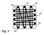
(単層31と、所望の方法でこの単層に取り付けられたコード33とを有する)単層パッチの1つの製造方法によれば、図3を参照すると、パッチ10は、共通の多孔質プレート(図示せず)に固定されたピン14の周りに(複数の連続フィラメントから形成された)コード13を巻回して形成される。不織材料の層12は、形成されたループ13の上部に配置されており、この層12は、次に、上述したような水流ジェット交絡を用いてコード13のループからなる群の様々な側の周りで機械的に交絡される。このプロセスによって、コード(例えば糸(yarn))13からなる強度を有するループで補強された複合パッチ10が提供される。図3には、ベース層12の境界16内に取り付けられた予備形成アレイ(13)を含むパッチ10が示されているが、図4には、ベース層12aの境界16aの外側に部分的に延びる予備形成アレイ(13a)を含むパッチ10aが示されている。
According to one method of manufacturing a single layer patch (having a
パッチ30(図5)が、2つの層31,34の間の中間に位置決めされたコード33を含む二層構造として形成される場合に、各層の繊維は、コード33を第1層31に取り付けるような同様の水流交絡プロセスを介して互いに交絡される。得られたパッチ30は、こうして、それぞれの構成要素の繊維をミクロンスケールで交絡させることによって、完全に接続し、一体化し、単一構造になる。
When the patch 30 (FIG. 5) is formed as a two-layer structure including a
コード33は、緩んだ(loose)構造を有する複合糸(yarn)を提供するように、フィラメントが単に軽く又は適度に撚り合わされたようなマルチフィラメントコードである。従って、個々のフィラメントは、層31の繊維との機械的交絡が可能になるように、複合糸の撚糸の一部としての独立した動きを可能にしている。具体的には、糸(yarn)33は、メートル当たり30から100回の撚りがかけられ、好ましくはメートル当たり約50回の撚りがかけられる。各フィラメントは、20〜50ミクロンの範囲の直径を含んでもよい。一実施態様では、糸(yarn)は、70〜100本のモノフィラメントから形成されている。
図4を参照すると、ループ形状コード13aは、長さ、幅、又は直径に亘って層12の表面上に延びており、それによって、ループ端部が境界13aを越えて延びており、完成したパッチにおいて、ループ端部がこの境界から張り出る又は飛び出る。すなわち、組立プロセス中に、図5の層31は、糸(yarn)がループを形成するために巻回されるようにピン14aのセット内に位置決めされる。図4aには、ループの構成を規定するピン14aの群が取り外された後のパッチ10aが説明されている。ループ端部15は、パッチ10の境界を越えて飛び出ており、様々なアプリケーションの目的に合わせて、約4ミリメートル(mm)〜15mmの間で変化するような長さであってもよい。このループは、所望の場合には、これらのループがパッチの境界をさらに越えて飛び出るような寸法にされる。狭いチャネルがループ端部15を受容するように調製された骨(図示せず)の形態として組織にパッチ10aを固定することが所望される。このような狭いチャネルは、直線状又は円形とすることができ、直線形状は、振動する鋸刃を用いて調製され、円形形状は、中空の薄肉リーマを用いて調製される。使用時には、ループ端部は、適当な器具を用いて環状チャンネル内に押し付けられ、そして時間と共に、ループを介した組織の内部成長によって、パッチ10aを骨に固定するであろう。ループをより長く形成することによって、ループ端部をこのチャネル内に配置するプロセスが容易になる。
Referring to FIG. 4, the loop-shaped
図6を参照すると、この複合パッチは、ピンの群を収容する大きな多孔質プレートを用いて何回かに分けて製造することができ、各ピンの群は、説明された複数のパッチのいずれかについてエンドレス群からなるアレイを巻回するためのものである。不織層61のより大きなシートが、プレートに押し付けられて、ピンによって貫通される。その後、このシートは、複数の領域、すなわちコード63のループからなる群62を支持しており、各群62は、より大きなシート61から適当に切断される。各群62は、パッチ60の異なる形状及び構成を提供するように、ループ形状コード63の同一又は異なる配置を含む。ループからなる群62は、領域63の間の横断糸によって一緒に接続されている。従って、治療用パッチからなるアレイは、時計回りの経路65,66,67,68及び69に従って単一の不織層64上の同じ糸(典型的には20〜50ミクロンの直径の連続的なモノフィラメントの群から構成される)を用いて形成されている。各パッチ領域70は、次に、パンチ又は同様のものを用いてより大きなシートから切断される。
Referring to FIG. 6, this composite patch can be manufactured in several batches using a large porous plate containing a group of pins, each group of pins being one of a plurality of the described patches. This is for winding an array of endless groups. A larger sheet of
理解されるように、図6に示される単一層構成は、図5を参照して説明された2層構造を形成するような別の層を含む。パッチの取り扱い特性を改善するために、複数の不織層のうちの1つを図5に示される層38等の緩い状態の織り層と交換する、又はこのような追加の層38を提供することが可能である。この緩い状態の織り層は、1つの不織層と組み合わせられる、又は2つの不織層の間に挟み込まれてもよい。例えば、織り層38を、(底面又は下面となりうる)ベース層31の外向きの対向面37に取り付けてもよく、及び/又は(上面又は外側面となりうる)層34の外向きの対向面37に取り付けてもよい。
As will be appreciated, the single layer configuration shown in FIG. 6 includes additional layers that form the two-layer structure described with reference to FIG. In order to improve the handling characteristics of the patch, one of the plurality of nonwoven layers is replaced with a loosely woven layer such as
この複合パッチは、腹腔鏡、関節鏡、胸腔鏡又は他の鍵穴手術技術に適している。図7a,7b及び図8を参照すると、好適な送達ツール40は、細長いシャフト41の一端部に存在するハンドルを含む。2つの平行な細長いピン43の形態の取外し可能な取り付け部材が、シャフト41の先端42から延びている。図7aを参照すると、パッチ45がピン43の間に挿入され、次に、フィンガ(finger)及びサム(thumb)を含むシャフト41を回転させることによって、パッチがピン43上及びこのピンの周りでロールされる。このロール形状構成において、パッチ45及び導入ツールの先端40は、切開部47を通して挿入される送達カニューレ46(図8参照)内の通路に適合しており、このカニューレは、その先端部を治療部位に位置決めされている。一旦ロール形状パッチ45がカニューレ46を介して治療部位に送達されると、シャフト41が、シャフトの先端においてパッチ45を展開するように反対方向に回転される。パッチが送達され、且つ生体内の所望の位置に正確に制御された方法で展開できるように、外科医は、次に、パッチのそれぞれの側を適切な位置に便利に固定することができる。
This composite patch is suitable for laparoscopic, arthroscopic, thoracoscopic or other keyhole surgical techniques. With reference to FIGS. 7 a, 7 b and 8, a
さらなる実施形態よれば、スリーブ又はシース(図示せず)は、このシースが、所望の方法で生体内で展開されるようにパッチ45から引き抜かれる又は切断されるように構成された状態で、ロール形状又は折り畳み構成としてパッチ45を取り囲むように位置決めされる。
According to a further embodiment, a sleeve or sheath (not shown) is rolled with the sheath configured to be withdrawn or cut from the
さらなる実施形態によれば、図5を参照すると、パッチは、いかなる不織繊維構造も利用せず、その代わりに、各層31,34は、表面35,36上に完全に又は部分的に延びる接着剤を含むフィルム状のポリマーシートを有する。従って、接着剤付き面35,36を一緒に押し付けることによって、両方の層31,34は、互いに強く接着され、且つそれら層の間に細長いコード33を挟み込む。コード33のループ形状構成は、従って、対向する接着面35,36の少なくとも一方又は両方に存在する接着剤によって保持される。あるいはまた上述したように、ヒートシール・プロセスを用いることができる。さらなる実施形態によれば、ポリマー層31,34は、生体吸収性又は非生体吸収性材料から形成されてもよい。
According to a further embodiment, referring to FIG. 5, the patch does not utilize any nonwoven fiber structure, instead each
重要なのは、コード33及び層31,34の材料が生体適合性を有することである。特定の実施形態によれば、コード33は、非生体吸収性であり、ポリエステルから形成される。特定の実施形態によれば、層31,34及び/又は糸33は、ループ形状コード33の周りの組織の内部成長を促進ために効果的な足場となるような、生体吸収性又はパーマネント(非生体吸収性)である。
What is important is that the material of the
一実施形態によれば、層31,34及び/又は糸31は、生体吸収性であり、絹又は絹ベースの材料を含む。別の特定の実施形態によれば、層31は、マルチフィラメント糸から形成された織物形態であり、このマルチフィラメント糸は、細長いコード33の糸と同一又は別の糸である。
According to one embodiment, layers 31, 34 and / or
Claims (27)
所望のパターンとして構成されるループ形状構成からなる予備形成アレイの形態の引張荷重支持要素であって、前記ループは少なくとも1つのループ戻り端部を含み、前記アレイは細長いフィラメント材料から形成されている、引張荷重支持要素と;
不織繊維材料のベース層と;を備えており、
(A)前記予備形成アレイは、該予備形成アレイがその構成を維持しながら手術中に操作されるように前記ベース層の片面に取り付けられており;
(B)前記少なくとも1つのループ戻り端部は、縫合糸等を受容して当該パッチを組織に取り付けるように作用し;
(C)前記ベース層の繊維は、前記アレイをベース層に取り付けるとともに前記所望のパターンを実質的に維持するように、前記ループ形状構成に交絡される、
パッチ。 A biocompatible therapeutic patch for treating human or animal tissue, the patch comprising:
A tensile load bearing element in the form of a preformed array configured in a loop-shaped configuration configured as a desired pattern, the loop including at least one loop return end, the array being formed from an elongated filament material A tensile load bearing element;
A base layer of non-woven fiber material;
(A) the preformed array is attached to one side of the base layer such that the preformed array is manipulated during surgery while maintaining its configuration;
(B) the at least one loop return end acts to receive a suture or the like and attach the patch to the tissue;
(C) The fibers of the base layer are entangled with the loop-shaped configuration to attach the array to the base layer and substantially maintain the desired pattern;
patch.
請求項1に記載のパッチ。 The fibers of the base layer are entangled in the loop shape configuration by a hydroentanglement process,
The patch according to claim 1.
請求項1又は2に記載のパッチ。 Another layer is attached to the preformed array;
The patch according to claim 1 or 2.
請求項3に記載のパッチ。 Said another layer is a non-woven fiber layer,
The patch according to claim 3.
請求項4に記載のパッチ。 The another layer is attached to the preformed array by hydroentangling the fibers of the other layer into the loop-shaped configuration.
The patch according to claim 4.
請求項1〜5のいずれかに一項に記載のパッチ。 Including at least one woven layer,
The patch according to any one of claims 1 to 5.
請求項6に記載のパッチ。 A woven layer is attached to the preformed array, and another nonwoven layer is attached to the woven layer such that the woven layer is effectively sandwiched between the nonwoven layers;
The patch according to claim 6.
請求項6又は7に記載のパッチ。 A woven layer is attached to the outward facing surface of the base layer;
The patch according to claim 6 or 7.
請求項6に記載のパッチ。 The patch comprises another nonwoven layer attached to the preformed array, and the woven layer is attached to an outwardly facing surface of the other nonwoven layer;
The patch according to claim 6.
請求項5〜9のいずれか一項に記載のパッチ。 The plurality of layers and the preformed array are entangled by a hydroentanglement process;
The patch according to any one of claims 5 to 9.
当該パッチを組織に取り付けるべく少なくとも1つのループ戻り端部によって縫合糸等を受容するような、所望のパターンとして構成されたループ形状構成からなる予備形成アレイの形態の引張荷重支持要素であって、前記アレイは細長いフィラメント材料から形成されている、引張荷重支持要素と;
前記所望のパターンを実質的に維持するように前記予備形成アレイが取り付けられたベース層と;
前記予備形成アレイの上に重なる別の層と;を備える、
パッチ。 A biocompatible patch that assists in the treatment of human or animal tissue, the patch comprising:
A tensile load bearing element in the form of a pre-formed array configured in a loop-shaped configuration configured as a desired pattern to receive sutures or the like by at least one loop return end to attach the patch to tissue, A tensile load bearing element formed from an elongated filament material;
A base layer to which the preformed array is attached to substantially maintain the desired pattern;
Another layer overlying the preformed array;
patch.
請求項11に記載のパッチ。 The base layer and the another layer are secured together with an adhesive;
The patch of claim 11.
請求項1〜12のいずれか一項に記載のパッチ。 The preformed array has a plurality of loop return ends;
The patch according to any one of claims 1 to 12.
請求項13に記載のパッチ。 The loop return end is disposed within a boundary of the base layer;
The patch according to claim 13.
請求項13に記載のパッチ。 At least one loop return end is disposed outside the boundary of the base layer;
The patch according to claim 13.
前記パッチを組織に取り付けるべく少なくとも1つのループ戻り端部によって縫合糸等を受容するように、所望のパターンとして構成されたループ形状構成からなる引張荷重支持用アレイを予備成形するステップであって、前記アレイは細長いフィラメント材料から形成される、予備成形するステップと;
所望のパターンを維持するために前記ベース層の繊維を前記ループ形状構成に交絡させることによって、不織繊維材料のベース層の表面に前記予備形成アレイを取り付けるステップと;を含む、
パッチ製造方法。 A method for producing a biocompatible therapeutic patch for treating human or animal tissue, the method comprising:
Preforming a tensile load bearing array comprising a loop-shaped configuration configured as a desired pattern to receive a suture or the like by at least one loop return end to attach the patch to tissue, Preforming the array from an elongated filament material;
Attaching the preformed array to a surface of a base layer of nonwoven fibrous material by entanglement of the base layer fibers in the loop-shaped configuration to maintain a desired pattern;
Patch manufacturing method.
請求項17に記載の製造方法。 The base layer fibers are entangled in the loop configuration by a hydroentanglement process;
The manufacturing method according to claim 17.
請求項17又は18に記載の製造方法。 The pre-formed array is formed by at least partially wrapping the array of elongate material around pins secured on a plate in an arrangement such that the array of desired patterns is provided.
The manufacturing method according to claim 17 or 18.
請求項19に記載の製造方法。 The plate is provided with a jet that operates to inject water through the base layer to entangle the fibers of the base layer into the loop-shaped configuration.
The manufacturing method according to claim 19.
請求項1〜15のいずれか一項に記載のパッチ。 The filaments of the array are in a relaxed state and 30-70 twists per meter are applied,
The patch according to any one of claims 1 to 15.
請求項1〜15又は請求項21のいずれか一項に記載のパッチ。 The filament diameter of the array is in the range of 20-50 microns,
The patch according to any one of claims 1 to 15 or claim 21.
請求項1〜15,請求項21又は請求項22のいずれか一項に記載のパッチ。 At least the base layer is bioabsorbable,
The patch according to any one of claims 1 to 15, claim 21, or claim 22.
請求項23に記載のパッチ。 Bioabsorbable silk forms the base layer;
24. A patch according to claim 23.
組織治療部位に少なくとも部分的に挿入することが可能なカニューレを含んでおり、該カニューレは、前記導入ツールの先端と折り畳まれた又はロール形状構成のパッチとが、前記カニューレの内部を基端から先端に貫通することを可能にするのに十分な大きさ及び/又は直径を有している、
キット。 A kit of parts according to claim 16, wherein the kit is
A cannula capable of being at least partially inserted into a tissue treatment site, wherein the cannula has a distal end of the introducer tool and a folded or rolled configuration patch from the proximal end to the interior of the cannula. Having a size and / or diameter sufficient to allow penetration through the tip;
kit.
コード止めを用いて、生体適合性パッチの第1側を第1の組織部位に固定するステップであって、前記パッチが:
第1面を有する不織材料の少なくとも1つの層と;
第1面に取り付けられたフィラメント状の細長いコードであって、該コードは、第1面上に延びるループとして配置されており、該ループのそれぞれの端部は、前記パッチを前記組織に取り付けるべくコード止めを受容することが可能な取付領域を規定する、細長いコードと;を備えており、
前記層の繊維は、前記層を前記コードに取り付けるとともに前記層の面に亘るループの位置を維持するために、前記コードのフィラメントに交絡される、前記固定するステップと;
前記コード止めを用いて前記パッチの第2側を第2の組織治療部位に固定して、前記パッチが第1及び第2の組織部位をブリッジする位置に固定されるステップと;を含み、
第1及び第2の組織部位における前記コード止めが、それぞれ第1及び第2の端部で少なくとも1つの同じループを通過する、
治療方法。 A method of tissue treatment for animals or humans, the method comprising:
Securing the first side of the biocompatible patch to the first tissue site using a cord stop, the patch comprising:
At least one layer of nonwoven material having a first side;
A filamentary elongated cord attached to a first surface, the cord being arranged as a loop extending on the first surface, each end of the loop being adapted to attach the patch to the tissue An elongated cord defining a mounting area capable of receiving a cord stop; and
The anchoring step wherein fibers of the layer are entangled with filaments of the cord to attach the layer to the cord and maintain the position of the loop across the face of the layer;
Securing the second side of the patch to a second tissue treatment site using the cord stop and securing the patch in a position to bridge the first and second tissue sites;
The cord stops at the first and second tissue sites pass through at least one same loop at the first and second ends, respectively.
Method of treatment.
カニューレの先端を組織治療部位に位置決めするステップと;
導入ツールを用いてカニューレを通じて基端から先端にパッチを通過させることによって、折り畳まれた又はロール形状構成のパッチを治療部位に導入するステップであって、前記パッチが:
第1面を有する不織材料の少なくとも1つの層と;
第1面に取り付けられたフィラメント状の細長いコードであって、該コードは、第1面上に延びるループとして配置されており、該ループのそれぞれの端部は、前記パッチを前記組織に取り付けるべくコード止めを受容することが可能な取付領域を規定する、細長いコードと;を備えており、
前記層の繊維は、前記層を前記コードに取り付けるとともに前記層の面に亘るループの位置を維持するために、前記コードのフィラメントに交絡される、前記導入するステップと;
前記コード止めを用いて生体適合性パッチの第1側を第1の組織部位に固定するステップと;
前記コード止めを用いて前記パッチの第2側を第2の組織治療部位に固定して、前記パッチが第1及び第2の組織治療部位をブリッジする位置に固定されるステップと;を含み、
第1及び第2の組織治療部位における前記コード止めが、それぞれ第1及び第2の端部において少なくとも1つの同じループを通過する、
方法。
An animal or human tissue treatment method comprising:
Positioning the tip of the cannula at the tissue treatment site;
Introducing a folded or rolled configuration patch into a treatment site by passing the patch from the proximal end to the distal end through a cannula using an introduction tool, the patch comprising:
At least one layer of nonwoven material having a first side;
A filamentary elongated cord attached to a first surface, the cord being arranged as a loop extending on the first surface, each end of the loop being adapted to attach the patch to the tissue An elongated cord defining a mounting area capable of receiving a cord stop; and
The introducing step wherein the fibers of the layer are entangled with the filaments of the cord to attach the layer to the cord and maintain the position of the loop across the face of the layer;
Securing the first side of the biocompatible patch to a first tissue site using the cord stop;
Securing the second side of the patch to a second tissue treatment site using the cord stop and securing the patch in a position to bridge the first and second tissue treatment sites;
The cord stops at the first and second tissue treatment sites pass through at least one and the same loop at the first and second ends, respectively.
Method.
Applications Claiming Priority (4)
| Application Number | Priority Date | Filing Date | Title |
|---|---|---|---|
| GBGB1113305.5A GB201113305D0 (en) | 2011-08-02 | 2011-08-02 | Connective tissue repair pad |
| GB1113305.5 | 2011-08-02 | ||
| GB201202241A GB201202241D0 (en) | 2012-02-09 | 2012-02-09 | Connective tissue repair |
| GB1202241.4 | 2012-02-09 |
Publications (1)
| Publication Number | Publication Date |
|---|---|
| JP2014529412A true JP2014529412A (en) | 2014-11-13 |
Family
ID=46598860
Family Applications (1)
| Application Number | Title | Priority Date | Filing Date |
|---|---|---|---|
| JP2014523380A Pending JP2014529412A (en) | 2011-08-02 | 2012-07-20 | Connective tissue treatment |
Country Status (4)
| Country | Link |
|---|---|
| US (1) | US20150127103A1 (en) |
| EP (1) | EP2739241B1 (en) |
| JP (1) | JP2014529412A (en) |
| WO (1) | WO2013017835A1 (en) |
Families Citing this family (12)
| Publication number | Priority date | Publication date | Assignee | Title |
|---|---|---|---|---|
| GB201113303D0 (en) | 2011-08-02 | 2011-09-14 | Xiros Ltd | Connective tissue repair pad |
| GB201301784D0 (en) * | 2013-02-01 | 2013-03-20 | Xiros Ltd | Connective tissue repair technology |
| GB201302114D0 (en) * | 2013-02-06 | 2013-03-20 | Xiros Ltd | Connective tissue repair |
| US10130457B2 (en) | 2014-03-05 | 2018-11-20 | Tela Bio, Inc. | Surgical attachment device |
| US9925035B2 (en) * | 2014-05-30 | 2018-03-27 | Oregon State University | Implanted passive engineering mechanisms and methods for their use and manufacture |
| US9670443B2 (en) | 2014-06-25 | 2017-06-06 | University Of Leeds | Tissue engineered constructs |
| EP3317448B1 (en) | 2015-06-30 | 2021-09-08 | Tela Bio, Inc. | Corner-lock stitch patterns |
| EP3324882B1 (en) | 2015-07-21 | 2023-10-25 | Tela Bio, Inc. | Compliance control stitching in substrate materials |
| US9820843B2 (en) | 2016-04-26 | 2017-11-21 | Tela Bio, Inc. | Hernia repair grafts having anti-adhesion barriers |
| EP3761963B1 (en) | 2018-03-09 | 2025-01-22 | Tela Bio, Inc. | Surgical repair graft |
| WO2020185688A1 (en) | 2019-03-08 | 2020-09-17 | Tela Bio, Inc. | Textured medical textiles |
| CN111419468B (en) * | 2020-04-24 | 2024-11-29 | 北京积水潭医院 | Medical artificial patch placement instrument under endoscope |
Family Cites Families (21)
| Publication number | Priority date | Publication date | Assignee | Title |
|---|---|---|---|---|
| DE3030972A1 (en) * | 1980-08-16 | 1982-04-01 | Institute für Textil- und Faserforschung Stuttgart, 7410 Reutlingen | SURGICAL SEWING THREAD |
| EP0145492A3 (en) | 1983-12-15 | 1987-01-21 | A.W.Showell (Surgicraft) Limited | Replacements for ligaments and tendons |
| CH665768A5 (en) | 1985-05-03 | 1988-06-15 | Sulzer Ag | ARTIFICIAL TAPE MADE OF TEXTILE HOSE. |
| US4839215A (en) * | 1986-06-09 | 1989-06-13 | Ceramed Corporation | Biocompatible particles and cloth-like article made therefrom |
| US5217495A (en) | 1989-05-10 | 1993-06-08 | United States Surgical Corporation | Synthetic semiabsorbable composite yarn |
| GB9306737D0 (en) * | 1993-03-31 | 1993-05-26 | Surgicarft Ltd | Ligament augmentation device |
| US8795332B2 (en) * | 2002-09-30 | 2014-08-05 | Ethicon, Inc. | Barbed sutures |
| GB9510624D0 (en) * | 1995-05-25 | 1995-07-19 | Ellis Dev Ltd | Textile surgical implants |
| GB9822775D0 (en) * | 1998-10-20 | 1998-12-16 | Surgicarft Ltd | Artificial ligament or biological tissue fixation devices |
| DE60035894T2 (en) * | 1999-12-03 | 2008-04-17 | The University Of Leeds | RECOVERY OF DAMAGED TISSUE |
| US8366787B2 (en) * | 2000-08-04 | 2013-02-05 | Depuy Products, Inc. | Hybrid biologic-synthetic bioabsorbable scaffolds |
| US6746458B1 (en) * | 2000-09-07 | 2004-06-08 | William G. Cloud | Mesh material to repair hernias |
| GB0024903D0 (en) | 2000-10-11 | 2000-11-22 | Ellis Dev Ltd | A textile prothesis |
| AU2002230941A1 (en) * | 2000-10-31 | 2002-05-15 | Prodesco, Inc. | Supported lattice for cell cultivation |
| EP1868534A4 (en) | 2005-02-18 | 2008-08-20 | Synthasome Inc | Synthetic structure for soft tissue repair |
| US20070041952A1 (en) * | 2005-04-18 | 2007-02-22 | Duke University | Three-dimensional fiber scaffolds for tissue engineering |
| WO2007027592A1 (en) * | 2005-08-29 | 2007-03-08 | Ams Research Corporation | System for positioning support mesh in a patient |
| US8591584B2 (en) * | 2007-11-19 | 2013-11-26 | Nuvasive, Inc. | Textile-based plate implant and related methods |
| GB2458878A (en) | 2008-03-04 | 2009-10-07 | Xiros Plc | An implantable prosthetic cord |
| US8579922B2 (en) * | 2009-10-05 | 2013-11-12 | Covidien Lp | Method of suture identification and mesh marking for orienting and locating a mesh during hernia repair |
| US8690960B2 (en) * | 2009-11-24 | 2014-04-08 | Covidien Lp | Reinforced tissue patch |
-
2012
- 2012-07-20 JP JP2014523380A patent/JP2014529412A/en active Pending
- 2012-07-20 US US14/235,885 patent/US20150127103A1/en not_active Abandoned
- 2012-07-20 WO PCT/GB2012/051747 patent/WO2013017835A1/en active Application Filing
- 2012-07-20 EP EP12741064.5A patent/EP2739241B1/en active Active
Also Published As
| Publication number | Publication date |
|---|---|
| WO2013017835A1 (en) | 2013-02-07 |
| US20150127103A1 (en) | 2015-05-07 |
| EP2739241A1 (en) | 2014-06-11 |
| EP2739241B1 (en) | 2017-09-06 |
Similar Documents
| Publication | Publication Date | Title |
|---|---|---|
| JP2014529412A (en) | Connective tissue treatment | |
| US11234807B2 (en) | Reinforced biological construct and method of reinforcing biological construct | |
| RU2535616C2 (en) | Suture filaments with notches and locks for tampons and methods for using them | |
| EP2995261B1 (en) | Soft anchor assembly with non-sliding flexible strand | |
| US9277918B2 (en) | Knotless suture system | |
| EP2774545B1 (en) | Knotless filamentary fixation devices | |
| JP6293522B2 (en) | Implant with adjustable filament ring | |
| JP6792929B2 (en) | Suture anchor with suture filament and suture tape | |
| US20110054524A1 (en) | Implantable prosthetic cord | |
| CN107072767B (en) | Implantable mesh and method of use | |
| CA2921342A1 (en) | Apparatus and method for syndesmosis fixation | |
| JP6290906B2 (en) | Adhesion system for fixing soft tissue to bone and insert used in soft tissue fixation system | |
| US20140222038A1 (en) | Connective tissue repair | |
| US20230056585A1 (en) | Anchoring device for soft tissue repair | |
| CN113825454B (en) | Felt material for use in a method for repairing or reinforcing human or animal soft tissue | |
| JP4670037B2 (en) | Surgical suture | |
| US20200178954A1 (en) | Flat surgical suture constructs with loops and methods of tissue fixation | |
| WO2009071984A1 (en) | Suturing device for a tendon or ligament | |
| US20250017720A1 (en) | Rotator Cuff Cable Reconstructions | |
| WO2024211557A1 (en) | Tape and suture construct assembly | |
| WO2024064058A1 (en) | Reinforced medical implant and method of use |