JP2014526086A - Storage gateway startup process - Google Patents
Storage gateway startup process Download PDFInfo
- Publication number
- JP2014526086A JP2014526086A JP2014519133A JP2014519133A JP2014526086A JP 2014526086 A JP2014526086 A JP 2014526086A JP 2014519133 A JP2014519133 A JP 2014519133A JP 2014519133 A JP2014519133 A JP 2014519133A JP 2014526086 A JP2014526086 A JP 2014526086A
- Authority
- JP
- Japan
- Prior art keywords
- gateway
- customer
- storage
- data
- service provider
- Prior art date
- Legal status (The legal status is an assumption and is not a legal conclusion. Google has not performed a legal analysis and makes no representation as to the accuracy of the status listed.)
- Granted
Links
Images


Classifications
-
- H—ELECTRICITY
- H04—ELECTRIC COMMUNICATION TECHNIQUE
- H04L—TRANSMISSION OF DIGITAL INFORMATION, e.g. TELEGRAPHIC COMMUNICATION
- H04L63/00—Network architectures or network communication protocols for network security
- H04L63/06—Network architectures or network communication protocols for network security for supporting key management in a packet data network
- H04L63/061—Network architectures or network communication protocols for network security for supporting key management in a packet data network for key exchange, e.g. in peer-to-peer networks
-
- H—ELECTRICITY
- H04—ELECTRIC COMMUNICATION TECHNIQUE
- H04L—TRANSMISSION OF DIGITAL INFORMATION, e.g. TELEGRAPHIC COMMUNICATION
- H04L63/00—Network architectures or network communication protocols for network security
- H04L63/08—Network architectures or network communication protocols for network security for authentication of entities
- H04L63/0823—Network architectures or network communication protocols for network security for authentication of entities using certificates
-
- H—ELECTRICITY
- H04—ELECTRIC COMMUNICATION TECHNIQUE
- H04L—TRANSMISSION OF DIGITAL INFORMATION, e.g. TELEGRAPHIC COMMUNICATION
- H04L63/00—Network architectures or network communication protocols for network security
- H04L63/10—Network architectures or network communication protocols for network security for controlling access to devices or network resources
-
- H—ELECTRICITY
- H04—ELECTRIC COMMUNICATION TECHNIQUE
- H04L—TRANSMISSION OF DIGITAL INFORMATION, e.g. TELEGRAPHIC COMMUNICATION
- H04L67/00—Network arrangements or protocols for supporting network services or applications
- H04L67/50—Network services
- H04L67/51—Discovery or management thereof, e.g. service location protocol [SLP] or web services
-
- H—ELECTRICITY
- H04—ELECTRIC COMMUNICATION TECHNIQUE
- H04L—TRANSMISSION OF DIGITAL INFORMATION, e.g. TELEGRAPHIC COMMUNICATION
- H04L63/00—Network architectures or network communication protocols for network security
- H04L63/08—Network architectures or network communication protocols for network security for authentication of entities
- H04L63/0807—Network architectures or network communication protocols for network security for authentication of entities using tickets, e.g. Kerberos
-
- H—ELECTRICITY
- H04—ELECTRIC COMMUNICATION TECHNIQUE
- H04L—TRANSMISSION OF DIGITAL INFORMATION, e.g. TELEGRAPHIC COMMUNICATION
- H04L63/00—Network architectures or network communication protocols for network security
- H04L63/20—Network architectures or network communication protocols for network security for managing network security; network security policies in general
-
- H—ELECTRICITY
- H04—ELECTRIC COMMUNICATION TECHNIQUE
- H04L—TRANSMISSION OF DIGITAL INFORMATION, e.g. TELEGRAPHIC COMMUNICATION
- H04L67/00—Network arrangements or protocols for supporting network services or applications
- H04L67/01—Protocols
- H04L67/10—Protocols in which an application is distributed across nodes in the network
- H04L67/1097—Protocols in which an application is distributed across nodes in the network for distributed storage of data in networks, e.g. transport arrangements for network file system [NFS], storage area networks [SAN] or network attached storage [NAS]
-
- H—ELECTRICITY
- H04—ELECTRIC COMMUNICATION TECHNIQUE
- H04L—TRANSMISSION OF DIGITAL INFORMATION, e.g. TELEGRAPHIC COMMUNICATION
- H04L67/00—Network arrangements or protocols for supporting network services or applications
- H04L67/50—Network services
- H04L67/56—Provisioning of proxy services
- H04L67/568—Storing data temporarily at an intermediate stage, e.g. caching
Landscapes
- Engineering & Computer Science (AREA)
- Computer Networks & Wireless Communication (AREA)
- Signal Processing (AREA)
- Computer Hardware Design (AREA)
- Computer Security & Cryptography (AREA)
- Computing Systems (AREA)
- General Engineering & Computer Science (AREA)
- Information Retrieval, Db Structures And Fs Structures Therefor (AREA)
- Information Transfer Between Computers (AREA)
Abstract
リモートサービスプロバイダへのゲートウェイを起動するための方法、装置、およびコンピュータがアクセス可能なストレージ媒体。ゲートウェイは、例えばリモートデータストアに顧客データを記憶するために、顧客ネットワーク上のプロセスとプロバイダと間のインターフェースとして機能する。ゲートウェイは、公開鍵、およびゲートウェイを説明するメタデータをプロバイダに送る。ゲートウェイは、プロバイダから起動鍵を受け取り、顧客ネットワーク上に該起動鍵を公表する。顧客は、鍵を取得し、該鍵を使用してプロバイダと通信して、ゲートウェイの名前を含む顧客情報を提供し、また、ゲートウェイの登録を許可する。プロバイダは、ゲートウェイに顧客情報を提供する。ゲートウェイは、顧客情報および鍵を使用して、プロバイダにセキュリティ証明書を要求する。プロバイダは、ゲートウェイにセキュリティ証明書を送る。ゲートウェイは、次いで、プロバイダを介して、顧客から構成情報を取得し得る。
【選択図】図16AA method, apparatus, and computer-accessible storage medium for activating a gateway to a remote service provider. The gateway serves as an interface between the process on the customer network and the provider, for example to store customer data in a remote data store. The gateway sends the public key and metadata describing the gateway to the provider. The gateway receives the activation key from the provider and publishes the activation key on the customer network. The customer obtains a key, communicates with the provider using the key, provides customer information including the name of the gateway, and authorizes gateway registration. The provider provides customer information to the gateway. The gateway uses the customer information and key to request a security certificate from the provider. The provider sends a security certificate to the gateway. The gateway may then obtain configuration information from the customer via the provider.
[Selection] Figure 16A
Description
多くの企業および他の組織は、コンピューティングシステムを(例えば、ローカルネットワークの一部として)同じ場所に配置するか、または代わりに(例えば1つ以上のプライベートもしくはパブリック中間ネットワークを介して接続される)複数の別々の地理的な場所に配置する等によって、それらの事業をサポートするために多数のコンピューティングシステムを相互接続する、コンピュータネットワークを運営する。例えば、膨大な数の相互接続されたコンピューティングシステムを収容するデータセンターは、単一の組織によって、およびそれを代表して運営されるプライベートデータセンター、ならびに顧客にコンピューティングリソースを提供する事業として事業体によって運営されるパブリックデータセンター等のように、一般化してきている。ネットワークアクセス、電力、および様々な顧客が所有するハードウェアの安全な導入設備を提供するパブリックデータセンターオペレータもあれば、ハードウェアリソースをそれらの顧客が利用できるようにすることも含む「フルサービス」設備を提供するパブリックデータセンターオペレータもある。しかしながら、標準的なデータセンターの規模および範囲が増大するにつれて、物理的コンピューティングリソースをプロビジョニング、監督、および管理する作業は、ますます複雑になってきている。 Many businesses and other organizations place computing systems in the same location (eg, as part of a local network) or alternatively (eg, connected through one or more private or public intermediate networks) ) Operate a computer network that interconnects multiple computing systems to support their business, such as by placing them in multiple separate geographical locations. For example, a data center that houses a vast number of interconnected computing systems is a private data center operated by and on behalf of a single organization, and a business that provides computing resources to customers. It has become commonplace, such as public data centers operated by business entities. Some public data center operators provide secure access to network access, power, and hardware owned by various customers, while others include making hardware resources available to those customers. Some public data center operators provide equipment. However, as standard data centers grow in size and scope, the task of provisioning, overseeing, and managing physical computing resources becomes increasingly complex.
商品ハードウェアのための仮想化技術の出現は、多様なニーズを伴う多数の顧客のための大規模なコンピューティングリソースを管理することに関して利益を提供しており、種々のコンピューティングリソースを複数の顧客が効率的かつ安全に共有することを可能にしている。例えば、仮想化技術は、単一の物理的コンピューティングマシンによってホストされる1つ以上の仮想マシンを各ユーザに提供することによって、単一の物理的コンピューティングマシンを複数のユーザの間で共有することを可能にし得、各仮想マシンは、ユーザが所与のハードウェアコンピューティングリソースの唯一のオペレータかつ管理者であるような幻想をユーザに提供する、別個の論理コンピューティングシステムとして作用するソフトウェアシミュレーションにする一方で、種々の仮想マシンの間でのアプリケーションの分離およびセキュリティも提供する。さらに、いくつかの仮想化技術は、複数の別個の物理的コンピューティングシステムに及ぶ複数の仮想プロセッサを伴う単一の仮想マシン等の、2つ以上の物理リソースに及ぶ仮想リソースを提供することができる。 The advent of virtualization technology for commodity hardware has provided benefits in managing large-scale computing resources for a large number of customers with diverse needs, and various computing resources It enables customers to share efficiently and securely. For example, virtualization technology shares a single physical computing machine among multiple users by providing each user with one or more virtual machines hosted by a single physical computing machine. Each virtual machine is a software that acts as a separate logical computing system that provides the user with the illusion that the user is the only operator and administrator of a given hardware computing resource While providing simulation, it also provides application isolation and security among the various virtual machines. In addition, some virtualization technologies may provide virtual resources that span two or more physical resources, such as a single virtual machine with multiple virtual processors that span multiple separate physical computing systems. it can.
別の例として、仮想化技術は、複数のデータストレージデバイスにわたって分散され得る仮想化データストアを各ユーザに提供することによって、データストレージハードウェアを、複数のユーザの間で共有することを可能にし得、各仮想化データストアは、ユーザがデータストレージリソースの唯一のオペレータおよび管理者であるような幻想をユーザに提供する、別個の論理データストアとして作用する。 As another example, virtualization technology allows data storage hardware to be shared among multiple users by providing each user with a virtualized data store that can be distributed across multiple data storage devices. In turn, each virtualized data store acts as a separate logical data store that provides the user with the illusion that the user is the only operator and administrator of the data storage resource.
ウェブサービス
従来のウェブモデルは、クライアントが、ウェブブラウザ等のHTTPクライアントプログラムを介して、ウェブリソース(例えば、アプリケーション、サービス、およびデータ)にアクセスすることを可能にする。ウェブサービスと称される技術が、ウェブリソースへのプログラム的アクセスを提供するために開発された。ウェブサービスは、ウェブサービスインターフェースを介したウェブサーバシステム等のウェブ接続されたコンピュータ上でホストされる、技術プラットフォーム(例えば、アプリケーションおよびサービス)およびデータ(例えば、製品カタログおよび他のデータベース)を含む、ウェブリソースへのプログラム的アクセスを提供するために使用され得る。概して、ウェブサービスインターフェースは、いくつかのサービスを行うように要求するクライアントとサービスプロバイダとの間の通信のために、標準クロスプラットフォームのAPI(アプリケーションプログラミングインターフェース)を提供するように構成され得る。いくつかの実現例において、ウェブサービスインターフェースは、サービス要求およびその要求に対する応答を説明する情報を含む文書またはメッセージの交換をサポートするように構成され得る。そのような文書またはメッセージは、例えばハイパーテキスト転送プロトコル(HTTP)等の標準化されたウェブプロトコルを使用して交換され得、また、例えば拡張マークアップ言語(XML)等のプラットフォームに依存しないデータフォーマットでフォーマットされ得る。
Web Services Traditional web models allow clients to access web resources (eg, applications, services, and data) via an HTTP client program such as a web browser. A technology called web services has been developed to provide programmatic access to web resources. Web services include technology platforms (eg, applications and services) and data (eg, product catalogs and other databases) hosted on a web-connected computer, such as a web server system via a web service interface, It can be used to provide programmatic access to web resources. In general, a web service interface may be configured to provide a standard cross-platform API (Application Programming Interface) for communication between a client and a service provider requesting to perform some services. In some implementations, the web service interface may be configured to support the exchange of documents or messages that include information describing service requests and responses to those requests. Such documents or messages can be exchanged using standardized web protocols such as hypertext transfer protocol (HTTP) and in a platform independent data format such as extensible markup language (XML). Can be formatted.
実施形態は、複数の実施形態および実例となる図面について一例として本明細書で説明されるが、当業者は、実施形態が、説明される実施形態または図面に限定されないことを認識するであろう。図面およびその詳細な説明は、実施形態を、開示される特定の形態に限定することを意図するものではなく、逆に、添付の特許請求の範囲によって定義される趣旨および範囲の範囲内に含まれる全ての修正物、均等物、および代替物を対象とすることを意図することを理解されたい。本明細書で使用される見出しは、編成目的のために過ぎず、説明または特許請求の範囲を限定するために使用されることを意味していない。本出願の全体を通して使用される「してもよい/し得る(may)」という用語は、義務的な意味(すなわち、「〜しなければならない」という意味)ではなく、許容的な意味(すなわち、「〜する可能性がある」という意味)で使用される。同様に、「含む(include)」、「含んでいる(including)」、および「含む(includes)」という用語は、「含むが、それらに限定されない」ことを意味する。 While embodiments are described herein by way of example for multiple embodiments and illustrative drawings, those skilled in the art will recognize that the embodiments are not limited to the described embodiments or drawings. . The drawings and detailed description thereof are not intended to limit the embodiments to the particular forms disclosed, but are instead encompassed within the spirit and scope as defined by the appended claims. It is to be understood that all modifications, equivalents, and alternatives intended are intended to be covered. The headings used herein are for organizational purposes only and are not meant to be used to limit the description or the claims. As used throughout this application, the term “may” is not an obligatory meaning (ie, meaning “must”), but an acceptable meaning (ie, , "May mean"). Similarly, the terms “include”, “including”, and “includes” mean “including but not limited to”.
ローカルゲートウェイをリモートストレージに提供するための方法、装置、およびコンピュータがアクセス可能なストレージ媒体の種々の実施形態の種々の実施形態が説明される。ストレージゲートウェイの実施形態は、インターネット等の中間ネットワークを通じて、ストレージサービスをサービスプロバイダの1人以上の顧客に提供する、サービスプロバイダに関連して本明細書で説明される。ストレージゲートウェイは、顧客のデータセンターで施設内に導入され、顧客のデータセンターとストレージサービスとの間のゲートウェイとして作用する、仮想または物理機器として実現され得る。ストレージゲートウェイは、ストレージサービスを介してリモートに提供される主ストレージへのインターフェースおよびそれのためのローカルキャッシュとして、ならびに/またはストレージサービスによって提供されるリモートストレージへの顧客のネットワーク上に実現される主ストレージをシャドウ化するインターフェースとして構成され得る。ストレージゲートウェイは、機器のフロントエンドで顧客のアプリケーションへの標準的なデータアクセスインターフェースを提示し、機器のバックエンドでデータアクセスをストレージサービス要求に変換し、そして、ストレージサービスインターフェースに従って、ネットワークを通じてデータをストレージサービスに転送し得る。少なくともいくつかの実施形態において、ストレージサービスインターフェースは、ウェブサービスインターフェースとして実現され得る。 Various embodiments of various embodiments of methods, apparatus, and computer accessible storage media for providing a local gateway to remote storage are described. Embodiments of storage gateways are described herein in connection with a service provider that provides storage services to one or more customers of the service provider over an intermediate network such as the Internet. The storage gateway may be implemented as a virtual or physical device that is installed in the facility at the customer's data center and acts as a gateway between the customer's data center and storage services. A storage gateway is implemented as an interface to the main storage provided remotely via the storage service and a local cache for it and / or on the customer's network to the remote storage provided by the storage service. It can be configured as an interface for shadowing storage. The storage gateway presents a standard data access interface to customer applications at the equipment front end, converts data access to storage service requests at the equipment back end, and then passes the data through the network according to the storage service interface. Can be transferred to storage service. In at least some embodiments, the storage service interface may be implemented as a web service interface.
ストレージゲートウェイの実施形態は、ストレージサービスを介して提供される本質的に無制限で、柔軟な、かつ拡張可能なリモートストレージへの施設内インターフェースを提供し得る。ストレージゲートウェイは、従来の施設内ストレージソリューションに対して、費用効果的で、柔軟な、かつより容易に拡張可能な代替物を提供し得る。ストレージデバイスの費用が削減され得るが、従来の施設内ストレージソリューションの管理費用、ならびに他のソフトウェアおよびハードウェア費用は、比較的一定のままであるか、または一部の場合では増加している。ストレージゲートウェイの実施形態は、サービスプロバイダの顧客が、ストレージ所有の総費用をより低減することを可能にし、少なくとも一部の管理費用および他の費用がサービスプロバイダにまわる。 Storage gateway embodiments may provide an in-house interface to an essentially unlimited, flexible, and scalable remote storage provided via storage services. Storage gateways can provide a cost-effective, flexible and more easily expandable alternative to traditional in-house storage solutions. While the cost of storage devices can be reduced, the management costs of traditional in-house storage solutions, as well as other software and hardware costs, remain relatively constant or in some cases have increased. Embodiments of storage gateways allow service provider customers to further reduce the total cost of storage ownership, with at least some administrative and other costs going to the service provider.
少なくともいくつかの実施形態において、ストレージサービスは、ブロックストレージ技術に従って、顧客のデータをリモートデータストアに記憶し得る。少なくともいくつかの実施形態において、ストレージゲートウェイは、フロントエンドで、ブロックストレージプロトコル(例えば、iSCSI、GNBD(グローバルネットワークブロックデバイス)等)、ファイルストレージプロトコル(例えば、NFS(ネットワークファイルストレージ)、CIFS(共通インターネットファイルシステム)等)、および/またはオブジェクトストレージプロトコル(例えば、REST(Representational State Transfer:表現可能な状態の転送))を顧客のアプリケーションに公表し得る。iSCSI等のブロックストレージプロトコルは、リモートデータストアの下層のデータブロックへの直接アクセスを可能にする。 In at least some embodiments, the storage service may store customer data in a remote data store according to block storage technology. In at least some embodiments, the storage gateway is a front-end, block storage protocol (eg, iSCSI, GNBD (Global Network Block Device), etc.), file storage protocol (eg, NFS (Network File Storage), CIFS (Common Internet file system), and / or object storage protocols (eg, REST (Representative State Transfer)) can be published to customer applications. Block storage protocols such as iSCSI allow direct access to data blocks below the remote data store.
ストレージゲートウェイによって公表されるNFSまたはCIFS等のファイルストレージプロトコルを介して、アプリケーションによってリモートデータストアに書き込まれるファイルは、ブロックストレージ技術に従って、リモートデータストアに記憶され得る。公表されたNFSおよびCIFS等のファイルストレージプロトコルを通して、ストレージゲートウェイは、ブロックストレージ技術に従ってリモートデータストアに記憶される顧客のデータが顧客のネットワークを通じてゲートウェイから顧客のアプリケーションに伝送される前に、該顧客のデータをファイルとして顧客のアプリケーションに提示する。公表されたブロックストレージプロトコル、例えばiSCSIは、ブロックを顧客のアプリケーションに転送し、したがって、アプリケーションは、データブロックをアプリケーションが求める何らかの形式に翻訳する処理を必要とする。 Files written to a remote data store by an application via a file storage protocol such as NFS or CIFS published by the storage gateway can be stored in the remote data store according to block storage technology. Through published file storage protocols such as NFS and CIFS, the storage gateway can store customer data stored in a remote data store according to block storage technology before it is transmitted from the gateway to the customer application through the customer network. Is presented to the customer's application as a file. A published block storage protocol, such as iSCSI, transfers the block to the customer's application, and thus the application requires processing to translate the data block into some form desired by the application.
iSCSI等のブロックストレージプロトコルは、低次ブロックストレージプロトコルであり、したがって、NFSおよびCIFS等のファイルストレージプロトコルよりも広い範囲の使用事例を可能にし得る。ブロックストレージプロトコルは、Microsoft(登録商標)、SharePoint(登録商標)、およびOracle(登録商標)データベース等の、一般的にブロックストアに書き込むアプリケーションに対するサポートを可能にし得、また、下層のストレージをCIFSまたはNFSファイルサーバに提供するようにも構成され得る。したがって、ストレージゲートウェイの少なくともいくつかの実施形態において、iSCSI等のブロックストレージプロトコルは、顧客のアプリケーションへの公表されたインターフェースとして利用され得る。 Block storage protocols such as iSCSI are low-order block storage protocols and may therefore allow a wider range of use cases than file storage protocols such as NFS and CIFS. The block storage protocol may allow support for applications that typically write to the block store, such as Microsoft®, SharePoint®, and Oracle® databases, and the underlying storage may be CIFS or It can also be configured to provide to an NFS file server. Thus, in at least some embodiments of the storage gateway, block storage protocols such as iSCSI can be utilized as a published interface to customer applications.
図1は、少なくともいくつかの実施形態による、例示的なサービスプロバイダおよび例示的なサービス顧客を含む、例示的なネットワーキング環境の高次ブロック図である。ストレージゲートウェイ84は、複数のリモートデータストレージ機能の1つ以上をクライアントネットワーク80上の顧客プロセス88(複数可)に提供するために、サービス顧客ローカルネットワークまたはデータセンター(例えば、クライアントネットワーク80)の中に仮想または物理機器として導入され、起動され、構成され得る。顧客プロセス88は、クライアントネットワーク80上に存在し、また、ゲートウェイ84のデータポートのデータプロトコル(例えば、iSCSIプロトコル)を介して、ストレージゲートウェイ84に接続し、それと通信することができる、任意のハードウェア、ソフトウェア、および/またはそれらの組み合わせであり得る。ストレージゲートウェイ84は、例えば、施設内ストレージデバイスとして機能し得、および/またはクライアントネットワーク80上の顧客プロセス(複数可)88とサービスプロバイダ60によって提供されるストレージサービス64との間のインターフェースとして機能し得る。ストレージサービス64に加えて、サービスプロバイダ60も、ハードウェア仮想化サービスが挙げられるが、それに限定されない、他のサービスをサービスプロバイダ60の顧客に提供し得ることに留意されたい。
FIG. 1 is a high-level block diagram of an example networking environment including an example service provider and an example service customer, according to at least some embodiments. The
サービスプロバイダ60の顧客は、本明細書において、サービス顧客または単に顧客と称され得、任意のエンティティであり得、該エンティティは、サービスプロバイダ60によってリモートに提供される1つ以上のサービスを含む、ネットワーク化されたコンピューティングサービスを、ローカルネットワークまたはネットワーク上の1人以上のユーザに提供するために、インターネット等の中間ネットワーク50に連結される、1つまたは複数のコンピュータネットワークを実現する。サービス顧客は、企業、教育機関、政府機関、または一般に、ネットワーク化されたコンピューティングサービスをユーザに提供する1つまたは複数のコンピュータネットワークを実現する任意の機関であり得る。図1は、単一のクライアントネットワーク80を示しているが、複数のクライアントネットワーク80があり得る。各クライアントネットワーク80は、異なるサービス顧客に対応し得、または2つ以上のクライアントネットワーク80が、同じサービス顧客の異なるデータセンターもしくは所在地、例えば企業の異なる支社もしくは学校組織の異なるキャンパスに対応し得る。少なくともいくつかの実施形態において、サービスプロバイダ60の各顧客は、サービスプロバイダ60とのアカウントを有し得、また、セキュリティ証明書(例えば、アカウント名および/または識別子、パスワード等)が提供され得、該セキュリティ証明書を介して、1人以上の顧客代表者(例えば、クライアントネットワーク管理者)は、サービスプロバイダ60へのインターフェース(例えば、ウェブページ)にログインして、サービスプロバイダ60によって提供される、ストレージサービスが挙げられるが、それに限定されない、1つ以上のサービスによって提供される、顧客のリソースを管理し得る。
A customer of
ストレージゲートウェイ84の実施形態は、ハードウェア、ソフトウェア、またはそれら組み合わせで実現され得る。少なくともいくつかの実施形態において、ストレージゲートウェイ84は、例えばホストシステム上でインスタンス化される仮想マシン内で実行し得る、仮想機器として実現され得る。少なくともいくつかの実施形態において、ストレージゲートウェイ84は、サービス顧客のデータセンターでローカルネットワークインフラストラクチャ(例えば、クライアントネットワーク80)に連結されるサーバシステム等の、1つ以上のコンピューティングデバイスにダウンロードまたは別様には導入され、起動され、そして構成され得る、仮想機器として実現され得る。あるいは、ストレージゲートウェイ84は、サービス顧客のデータセンターでローカルネットワークインフラストラクチャ(例えば、クライアントネットワーク80)に連結され得る、専用のデバイスまたは機器として実現され得、専用のデバイスまたは機器は、ストレージゲートウェイ84の機能を実現する、ソフトウェアおよび/またはハードウェアを含み得る。図26は、ストレージゲートウェイ84の実施形態が実現され得る、例示的なコンピュータシステムを図示する。少なくともいくつかの実現例において、ストレージゲートウェイ84は、ファイアウォール82技術を通して、中間ネットワーク50(例えば、インターネット)を介して、サービスプロバイダ60ネットワークと通信する。サービスプロバイダ60ネットワークはまた、中間ネットワーク50から、およびそれにネットワークトラフィックを渡す、フロントエンド62技術(例えば、ファイアウォール技術、境界ルータ技術、ロードバランサ技術等)も含み得ることに留意されたい。
Embodiments of
ストレージゲートウェイ84の少なくともいくつかの実施形態は、顧客に対するデータ保護、ならびに顧客または第三者によるゲートウェイ84の誤用および無許可の使用(例えば、権利の侵害)に対する保護を提供する、セキュリティモデルに従って実現され得る。ストレージゲートウェイ84とストレージサービス64との間の通信は、安全にされ、暗号化され得る。起動プロセスは、本文書において後で説明され、その中で、新たに導入されるストレージゲートウェイ84は、セキュリティ証明書を取得するために、サービスプロバイダ60のネットワークとの接続を開始し、それに識別される。少なくともいくつかの実施形態において、起動プロセス中に、顧客は、サービスプロバイダ60との顧客のアカウントにログインし、ゲートウェイ84を登録する際に使用される情報をサービスプロバイダ60に提供する。しかしながら、顧客は、ストレージゲートウェイ84にはログインせず、したがって、顧客のセキュリティ証明書および他のアカウント情報は、ゲートウェイ84上に公表されない。これは、顧客のセキュリティリスクを最小化し得る。
At least some embodiments of the
少なくともいくつかの実施形態において、セキュリティモデルの態様は、ストレージゲートウェイ84が、クライアントネットワーク80上の顧客プロセス(複数可)88に公表される1つ以上のデータポート(例えば、iSCSIポート)に対する、外部主導の接続だけを受け付ける。ストレージゲートウェイは、外部プロセスへの全ての他の接続を開始するが、外部プロセスは、ゲートウェイへの任意の他の接続を開始することができない。例えば、少なくともいくつかの実施形態において、ストレージゲートウェイ84は、ゲートウェイの管理およびサービスプロバイダ60への他の接続を開始するが、サービスプロバイダ60は、ゲートウェイ84への接続を開始しない。別の例として、クライアントネットワーク80のネットワーク管理者プロセス90は、ゲートウェイ84を較正および管理するために、ストレージゲートウェイ84に直接接続できない。代わりに、ネットワーク管理者プロセス90によるストレージゲートウェイ84の構成および管理は、例えばサービスプロバイダ60のネットワーク上のコンソールプロセス68を介して、サービスプロバイダ60を通して行われ得る。したがって、少なくともいくつかの実施形態において、クライアントネットワーク80上のユーザ、ネットワークマネージャ、またはプロセス(例えば、ネットワーク管理者プロセス90または顧客プロセス(複数可)88)は、ストレージゲートウェイ84に直接「ログインする」ことができず、また、サービスプロバイダ60のネットワーク上の、または他の何らかの外部ネットワーク上のユーザ、管理者、もしくはプロセス(例えば、コンソールプロセス68およびストレージサービス64)も、ストレージゲートウェイ84への接続を開始することができない。これは、ストレージゲートウェイ84関するセキュリティ証明書および他の操作情報が、クライアントネットワーク80上の人々もしくはプロセスによって、または外部の人々もしくはプロセスによって意図的に、または意図せずに危殆化されることから保護するのを補助する。
In at least some embodiments, an aspect of the security model is that the
ストレージゲートウェイ84の実施形態は、複数のデータストア66機能のうちの1つ以上を提供するために、ストレージサービス64とともに使用するように導入され、起動され、構成され得る。例えば、ストレージゲートウェイ84は、ストレージサービス64によって導入され、起動され、構成され、そして利用され得、次のように機能する。
● ファイルシステムゲートウェイ。この構成において、ストレージゲートウェイは、ストレージサービス64へのNASストレージインターフェース(例えば、CIFSまたはNFSプロトコルを使用する)として機能する。リモートデータストア66は、オブジェクトストア(例えば、REST)としてゲートウェイ84によって顧客に提示され得る一方で、データストア66は、ブロックストレージ技術に従って実現される。この構成において、リモートデータストア66は、顧客がファイルをそれに書き込むことができ、かつ顧客がそこからファイルを読み出すことができる仮想化ファイルシステムとして、顧客に提示され得る。
● クラウドボリュームゲートウェイ。この構成において、ストレージゲートウェイ84は、ストレージサービス64を介して、リモートデータストア66上に実現されるボリューム(複数可)へのインターフェースとして機能する。リモートデータストア66は、ブロックストレージ技術を使用して実現され得る。ゲートウェイ84は、ローカルネットワークアクセスポイントを提供し、リモートデータストア66上のボリューム(複数可)(クラウドボリュームとも称され得る)は、柔軟で本質的に無制限の主ストレージ容量を提供するバックエンドストレージとして機能する。この構成において、リモートデータストア66は、顧客がそこからデータを読み出し、書き込むためのボリュームをローカルにマウントすることができるクラウドボリュームシステムとして、顧客に提示され得る。
● シャドウ化ゲートウェイ。この構成において、ストレージゲートウェイ84は、顧客の書き込みデータ(例えば、iSCSI書き込み)のシャドウ化を、ストレージサービス84を介して、リモートデータストア66に提供するために、顧客のアプリケーション(例えば、顧客プロセス(複数可)88)と顧客のローカルデータストア86との間で、「バンプインザワイヤ」として作用する。リモートデータストア66は、ブロックストレージ技術を使用して実現され得る。この構成において、ストレージゲートウェイ84は、顧客のローカルデータストアをリモートデータストア66上のスナップショット(複数可)にシャドウ化する、シャドウ化機器としての役割を果たし得る。このシャドウ化は、ローカルネットワーク上のユーザの観点から透過的に行われ得る。必要であるかまたは所望されるときに、顧客は、例えば、スナップショット(複数可)からローカルストア86への顧客のデータの一部分または全てを回復、復元、またはコピーするために、リモートデータストア66上の顧客のデータのスナップショット(複数可)を要求し得、またはそれにアクセスし得る。
Embodiments of the
● File system gateway. In this configuration, the storage gateway functions as a NAS storage interface to the storage service 64 (eg, using CIFS or NFS protocol). The remote data store 66 may be presented to the customer by the
● Cloud volume gateway. In this configuration, the
● Shadowed gateway. In this configuration, the
ファイルシステムゲートウェイおよびクラウドボリュームゲートウェイは、どちらもリモートデータストアへのゲートウェイとしての役割を果たし得ること、およびどちらも、データ、例えば頻繁におよび/または最近使用されたデータをローカルにキャッシュし得ることが類似していることに留意されたい。ファイルシステムゲートウェイおよびクラウドボリュームゲートウェイの双方において、顧客プロセスからのデータ読み出しは、可能であれば、ローカルキャッシュから提供され得、可能でなければ、リモートデータストアから提供され得る。これに対して、シャドウ化ゲートウェイにおいて、データ読み出しは、ゲートウェイを通して顧客のローカルデータストアに渡される。この文書のために、ファイルシステムゲートウェイおよびクラウドボリュームゲートウェイは、これらの実現例とシャドウ化ゲートウェイを区別するために、集合的にキャッシュされたゲートウェイと称され得る。 Both file system gateways and cloud volume gateways can act as gateways to remote data stores, and both can cache data locally, for example frequently and / or recently used data Note that they are similar. In both the file system gateway and the cloud volume gateway, data retrieval from the customer process can be provided from a local cache if possible, or from a remote data store if not possible. In contrast, at the shadowing gateway, the data read is passed through the gateway to the customer's local data store. For the purposes of this document, file system gateways and cloud volume gateways may be referred to collectively as gateways to distinguish between these implementations and shadowed gateways.
例示的なストレージゲートウェイ機器のアーキテクチャ
図2は、少なくともいくつかの実施形態による、ストレージゲートウェイの例示的なアーキテクチャおよびその構成要素を図示する図である。図2で図示される構成要素のいくつかは、キャッシュされたゲートウェイの実現例と比較したときに、シャドウ化ゲートウェイの実現例では使用され得ず、または異なって使用もしくは実現され得ることに留意されたい。
Exemplary Storage Gateway Equipment Architecture FIG. 2 is a diagram illustrating an exemplary architecture of a storage gateway and its components, according to at least some embodiments. It is noted that some of the components illustrated in FIG. 2 may not be used in a shadowed gateway implementation or may be used or implemented differently when compared to a cached gateway implementation. I want.
ブロックドライバ10は、顧客プロセス88をストレージゲートウェイ84とインターフェースし、概して、ブロックドライバ10は、顧客プロセス88が(例えば、読み出し/書き込み要求を介して)ストレージゲートウェイ84と相互作用することを可能にする。ストレージゲートウェイ84は、顧客プロセス88とともにオンサイトであるので、プロセス88の観点から、データがローカルに記憶されるように見える。しかしながら、ストレージゲートウェイ84は、データをストレージサービス64によって提供されるリモートデータストア66に記憶するために、ストレージサービス64とインターフェースする。キャッシュされたゲートウェイについて、主データストアは、リモートデータストア66であるが、頻繁にアクセスされるデータは、ゲートウェイ84によってローカルにキャッシュされ得る。読み出しは、ローカルキャッシュから、または仮想データストレージ66から履行され得、書き込みは、ローカルキャッシュの中の、および/または仮想データストレージ66の中のデータブロックを適切に更新するように処理される。シャドウ化ゲートウェイについて、主データストアは、ローカルデータストア86であり、読み出しは、ローカルデータストア86に渡され、書き込みは、仮想データストレージ66にシャドウ化され、ならびに、ローカルデータストア86に送られる。
Block driver 10
ブロックドライバ10は、顧客プロセス88からの読み取り/書き込み要求をインターセプトし、該要求をストレージコントローラ12に渡す。少なくともいくつかの実施形態において、ブロックドライバ10は、顧客プロセス88へのインターフェースとして、ブロックストレージプロトコル(例えば、iSCSIまたはGMBD)を提供し得る。いくつかの実施形態において、ブロックストレージプロトコルインターフェースの代わりに、または代替例として、ブロックドライバ10は、ファイルストレージプロトコルインターフェース(例えば、NFSまたはCIFS)を提供し得、また、ストレージコントローラ12へのインターフェースとして、ファイルシステムセマンティクスを使用し得る。図2は、1つのブロックドライバ10を示しているが、2つ以上のブロックドライバがあり得ることに留意されたい。
The block driver 10 intercepts the read / write request from the
ストレージコントローラ12は、キャッシュマネージャ14を介して、ブロックドライバ10とストレージとの間のメディエータとして作用する。ストレージコントローラ12の責任としては、ブロックドライバ10からストレージに読み出しおよび書き込み要求を転送すること、およびストレージがデータで応答したときのブロックドライバ10へのコールバックが挙げられ得る。ブロックドライバ10はまた、進行中の要求の数等の統計も維持し得る。 The storage controller 12 acts as a mediator between the block driver 10 and the storage via the cache manager 14. Responsibilities of the storage controller 12 may include transferring read and write requests from the block driver 10 to the storage, and callbacks to the block driver 10 when the storage responds with data. Block driver 10 may also maintain statistics such as the number of requests in progress.
少なくともいくつかの実施形態において、一方のストレージゲートウェイ84上のストレージコントローラ12は、もう一方のストレージゲートウェイ84上のキャッシュマネージャ14と通信し得る。少なくともいくつかの実施形態において、各ストレージゲートウェイ84は、故障の発見および検出のためのハートビートメッセージを送り得る。所与のオブジェクトに対して責任を負うストレージゲートウェイ84を識別するために、コンシステントハッシングが使用され得、データを獲得するための要求は、ターゲットストレージゲートウェイ84上のキャッシュマネージャ14に転送され得る。キャッシュマネージャ14は、ストレージコントローラ12によって提供されるコールバックを起動することによって応答し得る。
In at least some embodiments, the storage controller 12 on one
キャッシュされたゲートウェイの実施形態において、キャッシュマネージャ14は、例えば頻繁にアクセスされるデータのためのストレージを提供する、ローカルキャッシュ28を管理し得る。ローカルキャッシュ28は、ストレージゲートウェイ84の内部揮発性および/または不揮発性メモリ上に実現され得るか、または代替として、顧客によって提供される外部ローカルデータストア86上に少なくとも部分的に実現され得る。少なくともいくつかの実施形態において、ローカルキャッシュ28は、仮想化データストレージ66に記憶されるデータを表し、顧客プロセス88からの書き込みは、ローカルキャッシュ28に直接的に影響を及ぼし得ない。
In a cached gateway embodiment, the cache manager 14 may manage a local cache 28 that provides storage for frequently accessed data, for example. The local cache 28 may be implemented on internal volatile and / or non-volatile memory of the
複数のゲートウェイ84を利用する少なくともいくつかの実施形態では、分散ローカルキャッシュが使用され得、所与の鍵を保持する責任を負うキャッシュを識別するために、鍵へのコンシステントハッシングが使用され得る。少なくともいくつかの実施形態では、さらなるロードバランシングを必要とし得る、ゲートウェイ84との間の通信を低減させるために、局所性を認識した要求の配信が使用され得る。
In at least some embodiments utilizing
リモートデータストア66の中の所与のボリュームへの全ての書き込み要求は、特定のゲートウェイ84ノードに進み得る。ボリュームに対する全ての書き込み要求が特定のゲートウェイ84ノードに転送されるので、ネットワークのパーティショニングは、問題になり得ない。
All write requests to a given volume in remote data store 66 may go to a
ステージング
少なくともいくつかの実施形態において、キャッシュマネージャ14は、ステージング16構成要素を含み得るか、またはそれとインターフェースし得る。ステージング16は、書き込みログ18へのアクセス含み得るか、または有し得る。少なくともいくつかの実施形態において、データ構造は、書き込みログ18を通じて構築され得、メタデータストア26として使用され得る。メタデータストア26は、特定のブロックに対する全ての書き込みへの高速アクセスを可能にすることができる。メタデータストア26は、例えば、変化をブロック内の異なるセグメントに適用する際に使用され得る。顧客プロセス88から書き込みデータを受け取ると、該データは、書き込みログ18に添付される。ブロックに関連する書き込みデータのメタデータ、例えばオフセットおよび長さは、メタデータストア26に記憶され得る。少なくともいくつかの実施形態において、書き込みログ18は、線形または循環どちらかのキューとして実現される、一次元のデータバッファとして実現され得る。少なくともいくつかの実施形態において、メタデータストア26は、例えばバークレーデータベースとして実現される、鍵/値ストアであり得る。いくつかの実施形態では、書き込みログ18およびメタデータストア26双方の他の実現例が使用され得る。
Staging In at least some embodiments, the cache manager 14 may include or interface with a staging 16 component. Staging 16 may include or have access to a write log 18. In at least some embodiments, the data structure can be built through the write log 18 and used as the metadata store 26. The metadata store 26 can allow fast access to all writes for a particular block. The metadata store 26 can be used, for example, in applying changes to different segments within a block. When write data is received from
キャッシュされたゲートウェイの実現例において、読み出しが行われたとき、元々のブロックは、ローカルキャッシュ28から、またはリモートデータストア66から取得され得、データをそれぞれの顧客プロセス88に返す前に、書き込みログ18によって示される任意の保留中の変化が適用され得る。
In a cached gateway implementation, when a read is performed, the original block may be obtained from the local cache 28 or from the remote data store 66 before writing data back to the
いくつかの実施形態において、ゲートウェイ84が故障(例えば、クラッシュ)した場合、インメモリ書き込みデータは、データが既にローカルデータストア86に書き込まれていない限り、失われ得る。いくつかの実施形態において、顧客サイトに複数のゲートウェイ84がある場合、別のゲートウェイ84は、クラッシュしたゲートウェイ84によって所有される鍵の責任を負い得、もしあれば、ローカルデータストア86上のスナップショットから書き込みを復旧し、そして、それぞれのボリュームに向けられた要求を受け付けることを開始し得る。いくつかの実施形態において、書き込みログ18および/またはメタデータストア26は、多重性およびより良い耐久性を提供するために、2つ以上のゲートウェイ84を通じて複製され得る。ゲートウェイ84が故障した場合、他のゲートウェイ84のうちの1つが、故障したゲートウェイの書き込みログ18およびメタデータストア26を引き継ぎ得る。しかしながら、少なくともいくつかの実施形態において、メタデータストア26は、所有者ゲートウェイ84上だけで維持され得る。これらの実施形態において、ゲートウェイ84が故障した場合、他のゲートウェイ84の1つは、メタデータストア26を再構築するために、主書き込みログ18を引き継ぎ、パースし得る。
In some embodiments, if the
キャッシュされたゲートウェイの実現例において、ブロックフェッチャ22は、ストレージサービス64を介して、リモートデータストア66から必要とされるブロックのセグメントをフェッチする。少なくともいくつかの実施形態において、ブロックフェッチャ22は、キャッシングのための完全なブロックをフェッチするために、遅延フェッチ手法を利用し得る。キャッシュされたゲートウェイおよびシャドウ化ゲートウェイの双方について、ブロックストア24は、ストレージサービス64を介して、ステージング16からリモートデータストア66にデータをプッシュする。少なくともいくつかの実施形態において、ブロックストア24は、ブロックをプッシュするために、遅延プッシュ手法を利用し得る。
In the cached gateway implementation, block fetcher 22 fetches the required segment of blocks from remote data store 66 via
少なくともいくつかの実施形態において、キャッシュされたゲートウェイの読み出し操作中に、ブロックドライバ10は、ボリュームID、開始オフセット、および長さを含む、読み出し要求をストレージコントローラ12に送る。少なくともいくつかの実施形態において、ストレージコントローラ12は、ボリュームIDおよびオフセットをオブジェクト鍵に変換し得る。ストレージコントローラ12は、読み出し要求情報をキャッシュコントローラ14に渡し、該キャッシュコントローラは、適切なローカルキャッシュ28から、読み出し要求を履行するよう試み得る。データがローカルキャッシュ28の中に存在しない場合、要求は、ブロックフェッチャ22に転送され、該ブロックフェッチャは、ストレージサービス64を介して、リモートデータストア66上の適切なボリュームからデータをフェッチする。データが取得されると、ローカルキャッシュ28が更新され、書き込みログ18から変化が適用され、読み出し応答が顧客プロセス88に返される。少なくともいくつかの実施形態において、複数のブロックが要求された場合は、それぞれが、それぞれのブロックの関連するオフセットを示す、複数の読み出し応答が返され得る。少なくともいくつかの実施形態では、逐次読み出しが検出された場合、逐次ブロックがプリフェッチされ得る。
In at least some embodiments, during a cached gateway read operation, the block driver 10 sends a read request to the storage controller 12, including the volume ID, starting offset, and length. In at least some embodiments, the storage controller 12 may convert the volume ID and offset into an object key. The storage controller 12 passes the read request information to the cache controller 14, which may attempt to fulfill the read request from the appropriate local cache 28. If the data is not present in the local cache 28, the request is forwarded to the block fetcher 22, which fetches the data from the appropriate volume on the remote data store 66 via the
少なくともいくつかの実施形態において、書き込み操作中に、ブロックドライバ10は、ボリュームIDおよび書き込みデータを含む書き込み要求を、ボリュームに対して責任を負う、ストレージコントローラ12に送る。書き込みデータは、書き込みログ18に書き込まれ、メタデータストア26は、バッファプール20の中の変化したデータへの参照を含むように更新される。 In at least some embodiments, during a write operation, the block driver 10 sends a write request including a volume ID and write data to the storage controller 12 responsible for the volume. Write data is written to the write log 18 and the metadata store 26 is updated to include references to changed data in the buffer pool 20.
バッファプール
少なくともいくつかの実施形態において、バッファプール20は、ストレージコントローラ12とローカルデータストア86との間に存在する。バッファプール20は、以下のタスクのうちの1つ以上を行い得るが、それらに限定されない。いくつかのタスクを、キャッシュされたゲートウェイだけに適用し得ることに留意されたい。
● ローカルデータストレージデバイス(複数可)上のそれらの物理的場所からの、書き込みログ18およびローカルキャッシュ28の論理オフセットのデータをキャッシュする。
● 読み出しおよび書き込み操作中に、バッファ上にロックを維持する。
● 追い出し手法、例えば最長未使用時間(LRU)追い出し手法を、ローカルキャッシュ28の物理ストレージに適用する。これは、ゲートウェイのシャドウ化には必要でないことに留意されたい。
● キャッシュされたゲートウェイにおける読み出しについて、要求されたデータがローカルキャッシュ28の中に見つからなかった場合は、バッファプール20がブロックフェッチャ22と通信して、リモートデータストア66からブロックをフェッチし得る。あるいは、いくつかの実施形態では、ブロックフェッチャ22がストレージサービス64と直接通信して、ブロックをフェッチし得る。
Buffer Pool In at least some embodiments, the buffer pool 20 exists between the storage controller 12 and the local data store 86. The buffer pool 20 may perform one or more of the following tasks, but is not limited to them. Note that some tasks may apply only to cached gateways.
Cache data at the logical offset of the write log 18 and local cache 28 from their physical location on the local data storage device (s).
● Maintain locks on the buffer during read and write operations.
• A eviction technique, such as a least recently used (LRU) eviction technique, is applied to the physical storage of the local cache 28. Note that this is not required for gateway shadowing.
For a read at the cached gateway, if the requested data is not found in the local cache 28, the buffer pool 20 may communicate with the block fetcher 22 to fetch a block from the remote data store 66. Alternatively, in some embodiments, block fetcher 22 may communicate directly with
少なくともいくつかの実施形態において、バッファプール20は、そのメタデータストア26として、データベース、例えばバークレーデータベース(BDB)を利用し得る。下で示される表1は、少なくともいくつかの実施形態による、メタデータストア26に記憶され得る情報を示す。表1のエントリは、内容または配設に従って制限することを意図しないことに留意されたい。 In at least some embodiments, the buffer pool 20 may utilize a database, such as a Berkeley database (BDB), as its metadata store 26. Table 1 shown below illustrates information that may be stored in the metadata store 26 according to at least some embodiments. Note that the entries in Table 1 are not intended to be limited according to content or arrangement.
少なくともいくつかの実施形態において、物理ディスクオフセットは、設定された境界、例えば4MB境界である。少なくともいくつかの実施形態において、これは、ボリュームおよび書き込みログ18の双方におけるデータの境界を含む。少なくともいくつかの実施形態において、特定のボリュームの書き込みは、逐次書き込みであり得、したがって、ディスク上の断片化を考慮することを必要とし得ない。「チャンク」は、1つのブロックまたは1つ以上のブロックに対応し得ることに留意されたい。 In at least some embodiments, the physical disk offset is a set boundary, eg, a 4MB boundary. In at least some embodiments, this includes data boundaries in both the volume and the write log 18. In at least some embodiments, the writing of a particular volume may be a sequential write and therefore may not require consideration for fragmentation on the disk. Note that a “chunk” can correspond to one block or more than one block.
メタデータストア26が、S(スナップショット)およびC(チャンク)エントリの双方を含み得ること、およびこれらを、ストレージコントローラ12がそれを介してブロックへのアクセスを試みるスキームによって、最新の状態に保つ必要があることに留意されたい。例えば、ブロックは、最初にスナップショットIDを使用して参照され得るが、その後は、毎回チャンクIDを使用して参照され得る。これは、メタデータストア26に保存され得る。スナップショットの完了時点で、ストレージコントローラ12は、スナップショットIDを使用して、スナップショットからブロックを参照し得、したがって、メタデータストア26の中のC(チャンク)エントリは、対応するS(スナップショット)エントリに変換され得る。 The metadata store 26 may contain both S (snapshot) and C (chunk) entries, and keep them up to date by the scheme through which the storage controller 12 attempts to access the block. Note that there is a need. For example, a block may first be referenced using a snapshot ID, but thereafter may be referenced using a chunk ID each time. This can be stored in the metadata store 26. At the completion of the snapshot, the storage controller 12 may reference the block from the snapshot using the snapshot ID, so the C (chunk) entry in the metadata store 26 will have a corresponding S (snapshot). Shot) entry.
キャッシュされたゲートウェイ操作
少なくともいくつかの実施形態では、読み出し要求を受け取ると、メタデータストア26において、ブロックの1つまたは複数の書き込みログ18エントリがルックアップされる。1つまたは複数の書き込みログ18エントリを使用して読み出し要求を履行することができる場合、メタデータストア26において、全ての必要とされるエントリがルックアップされ、バッファに読み出され、平坦化され、そして必要とされる部分が返される。1つまたは複数の書き込みログ18エントリを使用するだけでは読み出し要求を履行することができない場合、キャッシュデータブロック(例えば、4MBブロック)のオフセットが、読み出し要求のオフセットから計算される。メタデータストア26において、ブロックの場所がルックアップされる。ブロックがローカルキャッシュ28の中にある場合、ブロックは、ローカルキャッシュ28から読み出され、その中にない場合はリモートデータストア66からフェッチされる。必要とされる書き込みログ18エントリは、上で説明されるようにフェッチされ、ブロックで平坦化され、そして、必要とされる部分が返される。ブロックがリモートデータストア66からフェッチされる場合、ブロックは、ローカルキャッシュ28にキャッシュされ、メタデータストア26に記録される。ローカルキャッシュ28の中のブロックに対する最後のアクセス時間も更新される。
Cached gateway operations In at least some embodiments, upon receipt of a read request, one or more write log 18 entries of the block are looked up in the metadata store 26. If the read request can be fulfilled using one or more write log 18 entries, all required entries are looked up in the metadata store 26, read into a buffer and flattened. , And the required part is returned. If the read request cannot be fulfilled simply by using one or more write log 18 entries, the offset of the cache data block (eg, 4 MB block) is calculated from the offset of the read request. In the metadata store 26, the block location is looked up. If the block is in the local cache 28, the block is read from the local cache 28, otherwise it is fetched from the remote data store 66. The required write log 18 entries are fetched as described above, flattened in blocks, and the required portion is returned. When a block is fetched from the remote data store 66, the block is cached in the local cache 28 and recorded in the metadata store 26. The last access time for a block in the local cache 28 is also updated.
少なくともいくつかの実施形態では、書き込み要求を受け取ると、次の書き込みログ18オフセットで変化が記録され、メタデータ、すなわち、オフセットおよび長さがメタデータストア26に記録される。 In at least some embodiments, upon receiving a write request, the change is recorded at the next write log 18 offset, and the metadata, ie the offset and length, is recorded in the metadata store 26.
少なくともいくつかの実施形態では、ブロックのアップロードが完了すると、(変化が適用された)最新バージョンのブロックがローカルキャッシュ28に加えられ、メタデータストア26に記録される。以前のバージョンのブロックがローカルキャッシュ28に存在する場合、このブロックは、メタデータストア26の中で空きとしてマークされる。 In at least some embodiments, once the block upload is complete, the latest version of the block (with changes applied) is added to the local cache 28 and recorded in the metadata store 26. If a previous version block exists in the local cache 28, the block is marked as free in the metadata store 26.
少なくともいくつかの実施形態では、スナップショットが完了すると、上で説明されるように、メタデータストア26を再編成することが必要になり得る。すなわち、スナップショットに属するブロックエントリは、リモートデータストア66上の対応するスナップショットエントリに変換され得る。 In at least some embodiments, once the snapshot is complete, it may be necessary to reorganize the metadata store 26, as described above. That is, a block entry belonging to a snapshot can be converted into a corresponding snapshot entry on the remote data store 66.
シャドウ化ゲートウェイ操作
少なくともいくつかの実施形態において、読み出し要求は、ローカルデータストア86に渡される。
Shadowed gateway operation In at least some embodiments, the read request is passed to the local data store 86.
少なくともいくつかの実施形態では、書き込み要求を受け取ると、次の書き込みログ18オフセットで書き込みデータが記録され、書き込みの適切なメタデータがメタデータストア26に記録される。書き込み要求はまた、ローカルデータストア86にも渡される。 In at least some embodiments, upon receiving a write request, the write data is recorded at the next write log 18 offset and the appropriate metadata for the write is recorded in the metadata store 26. The write request is also passed to the local data store 86.
少なくともいくつかの実施形態では、ブロックをリモートデータストア66にアップロードするために、アップロードプロセスは、書き込みログ18を読み出すために、バッファプール20を呼び出す。バッファプール20は、メタデータストア26を使用して、論理書き込みログ18オフセットから物理オフセットへの変換を行い、次いで、データがメモリバッファに読み出される。バッファは、次いで、アップロードプロセスに提示される。アップロードプロセスは、ブロックをリモートデータストア66にアップロードし、ブロックをバッファプール20に発行する。 In at least some embodiments, to upload a block to the remote data store 66, the upload process calls the buffer pool 20 to read the write log 18. The buffer pool 20 uses the metadata store 26 to convert from the logical write log 18 offset to the physical offset, and then the data is read into the memory buffer. The buffer is then presented to the upload process. The upload process uploads the block to the remote data store 66 and issues the block to the buffer pool 20.
書き込みログのパージ
少なくともいくつかの実施形態では、書き込みログ18をパージする必要がある場合、バッファプール20は、書き込みログ18をパージすることができるボリュームのための書き込みログオフセットを取得する。少なくともいくつかの実施形態において、書き込みログオフセットは、例えば、各エントリのオフセットを確認する、データベース上のウォークを行うことによって、メタデータストア26から決定され得る。書き込みログ18をパージするために、ログのパージ可能な部分に対応する既存の書き込みログエントリが、空きエントリとしてマークされ得る。
Write Log Purging In at least some embodiments, when the write log 18 needs to be purged, the buffer pool 20 obtains a write log offset for the volume from which the write log 18 can be purged. In at least some embodiments, the write log offset may be determined from the metadata store 26, for example, by performing a walk on the database that checks the offset of each entry. To purge the write log 18, existing write log entries corresponding to the purgeable portion of the log can be marked as free entries.
例示的な実現例
図3は、ストレージゲートウェイの実施形態が実現され得る例示的なネットワーク環境の高次ブロック図である。中間ネットワーク100(例えば、インターネット)上のサービスプロバイダ110は、同じく中間ネットワーク100に連結される1つ以上のサービス顧客ネットワーク(例えば、クライアントネットワーク(複数可)150)に、ストレージサービス112を介してリモートデータストア116へのアクセスを提供する。各クライアントネットワーク150は、異なるサービス顧客に対応し得、または2つ以上のクライアントネットワーク150が、同じサービス顧客の異なるデータセンターまたは所在地、例えば企業の異なる支社もしくは学校組織の異なるキャンパスに対応し得る。サービス顧客は、企業、教育機関、政府機関、個人機関、または一般に、ネットワーク化されたコンピューティングサービスを1人以上のユーザに提供するために、インターネット等の中間ネットワーク100に連結される、1つまたは複数のコンピュータネットワークを実現する任意の機関であり得る。いくつかの実施形態において、ストレージサービス112は、インターフェース、例えばウェブサービスインターフェースを提供し得、それを介して、各サービス顧客のクライアントネットワーク(複数可)150は、ストレージサービス112によって提供される機能にアクセスし得る。
Exemplary Implementation Example FIG. 3 is a high-level block diagram of an exemplary network environment in which an embodiment of a storage gateway may be implemented. A service provider 110 on the intermediate network 100 (eg, the Internet) remotely communicates via a
顧客プロセス154Aおよび154Bは、サービス顧客のクライアントネットワーク150に接続される、物理マシンおよび/もしくは仮想マシンまたはシステムを表す。ストレージサービス112によって提供される機能の例として、ユーザは、顧客プロセス154を介して、データボリュームを作成し、ストレージサービス112を介して、リモートデータストア116にマウントすることができる。クライアントネットワーク150上のユーザの観点から、ストレージサービス112によって提供されるデータボリュームは、あたかもそれらがローカルストレージであるかのように現れ得、したがって、そのようなデータボリュームは、仮想データボリューム158と称され得る。仮想データボリューム158は、実際に、リモートデータストア116がインスタンス化される1つ以上の物理ストレージまたはストレージシステムにマップする。しかしながら、このマッピングは、ストレージサービス112によって処理され、したがって、クライアントネットワーク150上のユーザの観点からは透過的である。顧客プロセス154のユーザは、単にデスクトップ上にマウントされた、またはデバイスリストの中のボリュームだけが見え得る。顧客プロセス154のユーザは、あたかもボリューム158がローカルに取り付けられたストレージデバイス上に実現されたかのように、データを作成し、データを修正し、データを削除し得、また一般に、仮想データボリューム158に対して任意のデータ関連の機能を行い得る。
Customer processes 154A and 154B represent physical and / or virtual machines or systems connected to the service customer's
図4は、少なくともいくつかの実施形態による、クライアントネットワーク250とストレージサービス212との間のインターフェースとして機能する、サービス顧客のクライアントネットワーク250においてオンサイトのストレージゲートウェイ252を含む、例示的なネットワーク環境のブロック図である。少なくともいくつかの実施形態において、ストレージゲートウェイ252は、サービス顧客のデータセンターにおいてオンサイトで導入されるファイルおよび/またはブロックストレージ機器をしてもよい。
FIG. 4 illustrates an example network environment that includes an on-
ストレージゲートウェイ252は、例えば、ファイルシステムゲートウェイとしての、クラウドボリュームゲートウェイ(集合的にキャッシュされたゲートウェイと称される)としての、またはシャドウ化ゲートウェイとして機能するように、導入され、起動され、そして構成され得る。ファイルシステムゲートウェイは、(例えば、CIFSまたはNFSプロトコルを使用して)ストレージサービス212へのNASストレージインターフェースとして機能する。リモートデータストア216は、オブジェクトストア(例えば、REST)として顧客に提示され得るが、実際にはブロックストレージとして実現される。クラウドボリュームゲートウェイは、ストレージサービス212によって提供される仮想化ボリュームストレージへのインターフェースとして機能する。ボリュームストレージは、ブロックストレージとして実現され得る。ゲートウェイ252は、ローカルネットワークアクセスポイントを提供し、リモートデータストア216(クラウドボリュームとも称され得る)は、柔軟で本質的に無制限の主ストレージ容量を提供する、バックエンドストレージとして機能する。シャドウ化ゲートウェイは、顧客の書き込みデータ(例えば、iSCSI書き込み)のシャドウ化を、ストレージサービス212によって提供されるリモートストレージに提供するために、顧客のアプリケーションと顧客のローカルデータストアとの間の「バンプインザワイヤ」として作用する。リモートデータストア216は、ブロックストレージとして実現され得る。
The
キャッシュされたゲートウェイの実現例において、ストレージゲートウェイ252は、頻繁にアクセスされるデータのローカルキャッシュをローカルデータストア254に記憶し得る一方で、サービスプロバイダ210へ返すデータの移動を安全に暗号化し、迅速化する。同様に、シャドウ化ゲートウェイの実現例は、サービスプロバイダ210への書き込みデータの移動を安全に暗号化し、迅速化し得る。この迅速化されたデータの移動は、標準的なインターネット接続と比較して、例えば、データの重複排除、圧縮、並列化、およびTCPウインドウスケーリング手法のうちの1つ以上を使用して達成され得る。ストレージゲートウェイ252は、一般的に主ストレージまたはバックアップストレージとしてオンサイトストレージアレイを管理することと関連付けられる、費用、利用率、維持管理、およびプロビジョニングの問題を大幅に低減し得る。ストレージゲートウェイ252は、そうでない場合に顧客ごとに数100テラバイト〜ペタバイトのデータを社内で記憶させ得る、例えばNASまたはSANハードウェアといった、高価なハードウェアを、費用効果的な機器と置き換えることによってこれを達成し得る。ストレージゲートウェイ252によって、顧客は、オンサイトストレージ(キャッシュされたゲートウェイの実現例において、ゲートウェイ252によって維持されるローカルキャッシュによって提供される)の低アクセス待ち時間の利益を享受し得る一方で、サービスプロバイダ210によって提供される耐久性があり、有用で、かつ拡張可能な、分散ストレージインフラストラクチャを活用する。
In a cached gateway implementation, the
ストレージゲートウェイ252の実施形態は、顧客のオンサイトアプリケーションとともにシームレスに機能し得る。少なくともいくつかの実施形態において、顧客は、SAN(iSCSI)、NAS(NFS、Microsoft(登録商標)CIFS)、またはObject(REST)ストレージをサポートするように、ストレージゲートウェイ252を構成し得る。少なくともいくつかの実施形態において、ストレージゲートウェイ252によって提供されるiSCSIインターフェースは、Microsoft(登録商標)、SharePoint(登録商標)、およびOracle(登録商標)データベース等の、オンサイトのブロックストレージアプリケーションとの統合化を可能にし得る。少なくともいくつかの実施形態において、顧客は、Windows(登録商標)、Linux(登録商標)、およびUNIX(登録商標)環境が挙げられるが、それらに限定されない、環境全体にわたってファイルストレージを一元管理するために、ストレージゲートウェイ252によって提供されるNFSおよびCIFSインターフェースを利用し得る。少なくともいくつかの実施形態において、ストレージゲートウェイ252はまた、RESTに基づく要求をサポートするように構成され得る。
Embodiments of
少なくともいくつかの実施形態において、ストレージゲートウェイ252は、顧客のデータセンターでクライアントネットワーク250インフラストラクチャに連結されるサーバシステム等の、1つ以上のコンピューティングデバイスにダウンロードされ、または別様にはそれに導入され、起動され、そして構成され得る、仮想デバイスまたは機器として実現され得る。あるいは、ストレージゲートウェイ252は、クライアントネットワーク250インフラストラクチャに連結され得る、専用のデバイスまたは機器として実現され得、専用のデバイスまたは機器は、ゲートウェイの機能が実現され得る、ソフトウェアおよび/またはハードウェアを含み得る。
In at least some embodiments, the
少なくともいくつかの実現例において、ストレージゲートウェイ252は、中間ネットワーク200(例えば、インターネット)を介して、サービスプロバイダ210ネットワークと通信する。大量のデータが中間ネットワーク200を通じてストレージサービス212とストレージゲートウェイ252との間で転送され得るので、中間ネットワーク200へのストレージゲートウェイ252の連結は、一般に、サービス顧客のクライアントネットワーク250によって提供される広帯域の接続を介し得る。例えば、ピーク時間で、接続は、100メガビット/秒(100Mbit/s)以上の速度でのデータ転送をサポートする必要があり得る。しかしながら、少なくともいくつかの実施形態では、ストレージゲートウェイ252からストレージサービス212にデータをアップロードするときの帯域幅使用量を低減させるために、データ重複排除手法等の手法が利用され得、したがって、より多くの接続の帯域幅が他のアプリケーションで利用可能であり得る。少なくともいくつかの実施形態において利用され得る例示的なデータ重複排除手法は、米国特許出願第12/981,393号、名称「RECEIVER−SIDE DATA DEDUPLICATION IN DATA SYSTEMS」、および米国特許出願第第12/981,397号、名称「REDUCED BANDWIDTH DATA UPLOADING IN DATA SYSTEMS」で説明される。
In at least some implementations, the
少なくともいくつかの実施形態において、中間ネットワーク200を通じたクライアントネットワーク250とサービスプロバイダ210との間の接続に関する帯域幅は、例えばクライアントネットワーク250でネットワーク管理者プロセス260を介して、ストレージゲートウェイ252および他の顧客アプリケーションに割り当てられ得る。ストレージゲートウェイ252は、例えばデータ重複排除手法に従って、変化した(新しいまたは変更された)データをストレージサービス212に、連続的またはほぼ連続的にアップロードし得る。しかしながら、クライアントネットワーク250のデータの変化率は、経時的に変動し得、例えば、日中の顧客プロセスの書き込みスループットはより高くなり得るが、夜間の書き込みスループットはより低くなり得る。したがって、変化率が高い混雑時に、ストレージゲートウェイ252は、ストレージゲートウェイ252に割り当てられる帯域幅が、遅れを生じないよう十分高くない場合に、変化したデータをアップロードする際に遅れを生じ得、ストレージゲートウェイ252は、次いで、変化率がそれほど高くない非混雑時に、遅れを取り戻し得る。少なくともいくつかの実施形態において、ストレージゲートウェイ252が規定の閾値よりも遅れる場合、ストレージゲートウェイ252は、さらなる帯域幅の割り当てを要求し得る。少なくともいくつかの実施形態において、ストレージゲートウェイ252は、必要であれば、より多くの帯域幅を要求するために警報を発し得る。
In at least some embodiments, the bandwidth associated with the connection between the
図4は、ストレージゲートウェイ252とストレージサービス212との間の直接接続を示しているが、ストレージゲートウェイ252とストレージサービス212と間の接続は、ローカルネットワーク256を経由し得ることに留意されたい。
Although FIG. 4 illustrates a direct connection between the
ストレージゲートウェイ252の少なくともいくつかの実施形態では、要求に応じてリモートデータストア216からデータを取り出すのではなく、大きいデータのブロックまたはチャンク、さらにはデータのボリューム全体が、ローカルデータストア254にローカルにキャッシュされ得る。ストレージゲートウェイ252は、データのローカルキャッシュ、例えば頻繁にアクセスされるデータまたは重要なデータが維持され得る、物理データストレージおよび/またはメモリ(ローカルデータストア254)を含み得るか、またはそれへのアクセスを有し得る。ローカルデータストア254は、揮発性もしくは不揮発性ストレージもしくはメモリ、またはその組み合わせであり得る。頻繁にアクセスされるデータのローカルキャッシュを維持することは、リモートデータストア216からデータを取り出すのではなく、多数のまたは大部分のデータアクセスをローカルキャッシュから提供することができるので、一般に、顧客プロセス258のデータアクセス時間を改善し得る。しかしながら、リモートデータストア216は、サービス顧客のクライアントネットワーク250の主データストアとしての役割を果たし得、したがって、ストレージゲートウェイ252は、ローカルキャッシュからリモートデータストア216に新しいまたは修正されたデータを定期的に、非定期的に、または連続的にアップロードするために、および必要に応じて、リモートデータストア216から要求されたデータをダウンロードするために、中間ネットワーク200を介して、ストレージサービス212と通信し得る。
In at least some embodiments of the
図4において、リモートデータストア216のストレージ(218A、218B、218C、...)は、リモートデータストア216が、サービスプロバイダ210のローカルネットワーク214に接続される複数の記憶デバイスもしくはシステム上に、またはそれらの全体にわたって実現され得ることを示す。したがって、サービス顧客のデータは、「バックエンド」上の2つ以上の物理ストレージデバイスまたはシステムにわたって展開され得る。バックエンドストレージデバイスは、必ずではないが、他の顧客と共有されるマルチテナントデバイスであり得る。しかしながら、図3に関して述ベられるように、ユーザおよびクライアントネットワーク250上のプロセスの観点から、クライアントのデータは、仮想ボリュームまたはファイルとして提示され得る。
4, the storage (218A, 218B, 218C,...) Of the
少なくともいくつかの実施形態において、図3および図4を参照して説明されるサービスプロバイダはまた、ハードウェア仮想化技術および場合により他の仮想化技術を顧客に提供し得る。サービスプロバイダ200は、ブロックストレージ能力(すなわち、ブロックに基づくストレージシステム)を顧客に提供するブロックストレージ技術を含む、一連の仮想化コンピューティング技術および仮想化ストレージ技術を提供し得る。サービスプロバイダ200によって提供されるハードウェア仮想化技術に従って実現される、仮想コンピューティング環境またはシステムは、ブロックストレージ技術によってサポートされ得る。ブロックストレージ技術は、仮想化ストレージシステムを提供し得、該仮想化ストレージシステムは、例えば、標準化されたストレージコールを通して仮想コンピューティングシステムと相互作用することができ、該ストレージコールは、それがサポートするボリュームの構造的および機能的詳細を問わず、また、それがストレージの可用性を提供する仮想コンピューティングシステム(または他のシステム)上で実行するオペレーティングシステムを問わない、ブロックレベルのストレージ機能を提供する。
In at least some embodiments, the service provider described with reference to FIGS. 3 and 4 may also provide customers with hardware virtualization technologies and possibly other virtualization technologies. The
ストレージゲートウェイ252の実施形態は、サービスプロバイダ200によって提供されるオンサイトの顧客アプリケーションならびに仮想化コンピューティングおよびストレージ技術と統合し得、柔軟な「クラウドに基づく」コンピューティングおよびストレージリソースへのアクセスを顧客に提供する。例えば、SANストレージにストレージゲートウェイ252を使用する顧客は、それらのデータの一貫したポイントインタイムのブロックに基づくスナップショットを作成し得る。これらのスナップショットは、次いで、ブロックに基づくストレージシステムを提供する高I/Oおよび低待ち時間のデータアクセスを必要とする、ハードウェア仮想化技術アプリケーションおよびインスタンス(例えば、図5の仮想コンピューティングシステム(複数可)264を参照されたい)によって処理され得る。別の例として、顧客は、NFSまたはCIFSファイルプロトコルを介してNASストレージのストレージゲートウェイ252を構成し得、また、ハードウェア仮想化技術インスタンスからアクセス可能なそれらのファイルデータのポイントインタイムのスナップショットを作成し得る。
Embodiments of the
いくつかの実施形態において、ストレージゲートウェイ252によって提供されるRESTに基づくインターフェースを使用して書き込まれるオブジェクトは、HTTPまたは他のプロトコルを介してサービスプロバイダによって提供される仮想ストレージ技術から直接アクセスされ得るか、またはサービスプロバイダによって提供される統合したコンテンツ配信技術を使用して配信され得る。いくつかの実施形態において、顧客はまた、ハードウェア仮想化技術インスタンス上でこれらのオブジェクトを並列に処理するための仮想化ストレージ技術によって提供される、高い拡張可能性の分散型インフラストラクチャも利用し得る。
In some embodiments, objects written using a REST-based interface provided by the
図5は、少なくともいくつかの実施形態による、ストレージサービスおよびハードウェア仮想化サービスをサービスプロバイダの顧客に提供する、例示的なサービスプロバイダのブロック図である。サービス顧客のクライアントネットワーク250は、例えば図4を参照して説明されるように、クライアントネットワーク250とサービスプロバイダ210のストレージサービス212との間のインターフェースとして機能する、1つ以上のストレージゲートウェイ252を含み得る。サービスクライアント(複数可)は、管理者、ユーザ、またはサービスプロバイダ210によって提供されるサービスの1つにアクセスし得る任意のプロセスを表し得る。
FIG. 5 is a block diagram of an exemplary service provider that provides storage service and hardware virtualization services to service provider customers in accordance with at least some embodiments. The service customer's
ハードウェア仮想化技術は、複数のオペレーティングシステムが、ホストコンピュータ292上で並行して、すなわち、ホスト292上の仮想マシン(VM)296として動作することを可能にする。VM296は、例えば、サービスプロバイダ210の顧客に対して貸借され得る。ホスト292上のハイパーバイザーまたは仮想マシンモニタ(VMM)294は、仮想プラットフォームを伴うホスト292上のVM296を提示し、VM296の実行を監視する。各VM296には、1つ以上のIPアドレスが提供され得、ホスト292上のVMM294は、ホスト上のVM296のIPアドレスを認識し得る。サービスプロバイダ210のローカルネットワークは、パケットを、VM296からインターネットの宛先(例えば、クライアントネットワーク250上のサービスクライアント(複数可)262)に、およびインターネットソース(例えば、サービスクライアント(複数可)262)からVM296にルーティングするように構成され得る。
Hardware virtualization technology allows multiple operating systems to operate on the host computer 292 in parallel, ie, as a virtual machine (VM) 296 on the host 292. The VM 296 may be lent to a customer of the
サービスプロバイダ210は、ローカルネットワーク256を介して中間ネットワーク200に連結される、サービス顧客のクライアントネットワーク250に、中間ネットワーク200およびサービスプロバイダ210のローカルネットワークに連結されるハードウェア仮想化サービス290を介して、仮想コンピューティングシステム264を実現する能力を提供する。いくつかの実施形態において、ハードウェア仮想化サービス290は、インターフェース、例えばウェブサービスインターフェースを提供し得、サービスクライアント262は、それを介して、ハードウェア仮想化サービス290によって提供される機能にアクセスし得る。サービスプロバイダ210で、各仮想コンピューティングシステム264は、サービス顧客に対して貸借され、または別様には提供される、ホスト292システム上の仮想マシン(VM)296を表し得る。
The
仮想コンピューティングシステム264のインスタンスから、ユーザは、上で説明されるように、ストレージサービス212の機能にアクセスし得る。したがって、図5で示される仮想化システムの実施形態は、クライアントが、サービスプロバイダ210によって提供されるVM296上に実現される仮想コンピューティングシステム264のローカルインスタンスを作成すること、および仮想コンピューティングシステム264のローカルインスタンスから、サービスプロバイダ210によって実現されるリモートデータストア216からのデータにアクセスし、データをそれに記憶することを可能にし得る。
From an instance of the
上で説明されるように、1つ以上のストレージゲートウェイ252は、クライアントネットワーク250でインスタンス化され得る。ゲートウェイ252の少なくとも1つは、少なくともいくつかのデータ、例えば頻繁にアクセスされる、または重要なデータをローカルにキャッシュする、キャッシュされたゲートウェイの実現例であり得る。ストレージゲートウェイ(複数可)252は、例えば、キャッシュされたゲートウェイの実現例で、データの主ストア(リモートデータストア216)が維持されるように、ローカルキャッシュから新しいまたは修正されたデータをアップロードするために、またはシャドウ化ゲートウェイの実現例で、新しいまたは修正されたデータ(書き込みデータ)をリモートデータストア216上のローカル主データストアのスナップショットにアップロードするために、1つ以上の広帯域通信チャネルを介して、ストレージサービス212と通信し得る。
As described above, one or
キャッシュされたゲートウェイの実現例
図6は、ストレージゲートウェイの実施形態が、集合的にキャッシュされたゲートウェイと称される、ファイルシステムゲートウェイまたはクラウドボリュームゲートウェイとして構成される例示的なネットワーク環境のアーキテクチャおよびその中のデータフローを大まかに図示する、高次ブロック図である。少なくともいくつかの実施形態において、ストレージゲートウェイ252は、サービス顧客のデータセンターにおいてオンサイトで導入される、ファイルおよび/またはブロックストレージ機器であり得る。図6において、ストレージゲートウェイ252は、例えば、ファイルシステムゲートウェイとして、またはクラウドボリュームゲートウェイとして機能するように、導入され、起動され、そして構成され得る。ファイルシステムゲートウェイは、ストレージサービス212へのNASストレージインターフェース(例えば、CIFSまたはNFSプロトコルを使用する)として機能する。リモートデータストア216は、オブジェクトストア(例えば、REST)として顧客に提示され得る一方で、ブロックストレージとして実現される。クラウドボリュームゲートウェイは、ストレージサービス212によって提供される仮想化ボリュームストレージへのインターフェースとして機能する。仮想化ボリュームストレージは、ブロックストレージとして実現され得る。ゲートウェイ252は、ローカルネットワークアクセスポイントを提供し、リモートデータストア216(クラウドボリュームとも称され得る)は、柔軟で本質的に無制限の主ストレージ容量を提供する、バックエンドストレージとして機能する。
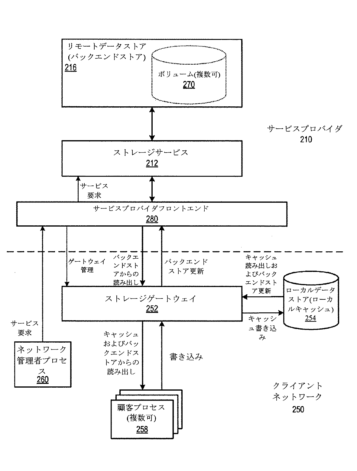
Cached Gateway Implementation Example FIG. 6 illustrates an exemplary network environment architecture in which an embodiment of a storage gateway is configured as a file system gateway or cloud volume gateway, collectively referred to as a cached gateway, and its FIG. 3 is a high-order block diagram that roughly illustrates the data flow within. In at least some embodiments, the
ストレージゲートウェイ252が導入され、起動され、そして構成されると、クライアントネットワーク250のネットワーク管理者プロセス260は、例えば、ストレージサービス212を介して、リモートデータストア216上に、新しいデータボリューム270を作成し得るか、または既存のデータボリューム270をマウントし得る。ボリューム要求および他のサービス要求の作成は、サービスプロバイダフロントエンド280を介して、サービス212に対して行われ得る。フロントエンド280はまた、ストレージゲートウェイ252への、およびそこからの接続および通信を管理し得る。フロントエンド280としては、ファイアウォール、境界ルータ、ロードバランサ、ゲートウェイサーバ、ゲートウェイプロキシ、コンソールプロセス、ならびに一般に、ストレージサービス212をクライアントネットワーク(複数可)250に公表するために、およびストレージサービス212をストレージゲートウェイ(複数可)252にインターフェースするために必要であり得る、任意のネットワーキングデバイスおよび/もしくはプロセスのうちの1つ以上が挙げられ得るが、それらに限定されない。
When the
少なくともいくつかの実施形態において、ストレージゲートウェイ252は、サービスプロバイダフロントエンド280を介して、サービスプロバイダ210への全ての接続を開始し、サービスプロバイダ210は、ゲートウェイ252への接続を開始しない。加えて、ネットワーク管理者プロセス260は、ゲートウェイ252への接続を直接開始せず、例えばゲートウェイ252を構成し、管理するための、ネットワーク管理者プロセス260によるゲートウェイ252へのアクセスは、サービスプロバイダフロントエンド280を介して、サービスプロバイダ210を通る。
In at least some embodiments, the
ストレージゲートウェイ252は、1つ以上のデータポート(例えば、iSCSIポート)をクライアントネットワーク250上の顧客プロセス258に公表する。顧客プロセス258は、クライアントネットワーク250上に存在し、また、ゲートウェイ252のデータポートのデータプロトコル(例えば、iSCSIプロトコル)を介して、ストレージゲートウェイ252に接続し、それと通信することができる、任意のハードウェア、ソフトウェア、および/またはそれらの組み合わせであり得る。顧客プロセス258は、例えば、Microsoft(登録商標)、SharePoint(登録商標)、およびOracle(登録商標)データベース等のストレージアプリケーション、サーバ(例えば、SQLサーバ、Microsoft(登録商標)Exchange(登録商標)サーバ等)、データベースアプリケーション(例えば、SQLデータベースアプリケーション、およびOracle(登録商標)データベースアプリケーション)、Microsoft(登録商標)Exchange(登録商標)アプリケーション、またはストレージゲートウェイ252データポート(複数可)と通信するように動作可能であるクライアントネットワーク250上の1つ以上のデバイス上で実行する、任意の他のアプリケーションまたはプロセスであり得る。顧客プロセスは、本明細書で使用されるときに、クライアントネットワーク250の中の1つ以上のデバイス上で実行され得る、任意のソフトウェアプロセスを包含する。しかしながら、プロセスを実行する下層のハードウェアは、プロセスを代表するストレージゲートウェイ252データポート(複数可)に対する接続および通信に関与し得るか、またはそれらを行い得ることに留意されたい。
マウントされたボリューム270は、ストレージゲートウェイ252によって顧客プロセス(複数可)258に提示され得る。顧客プロセス(複数可)258は、次いで、例えばiSCSIプロトコルに従って、ストレージゲートウェイ252によって公表されるデータポートを介した、ボリューム270からの読み出し、およびそれへの書き込みを行い得る。ストレージゲートウェイ252は、ボリューム270への全ての読み出しおよび書き込み要求を処理する。リモートデータストア216上のボリューム(複数可)270は、主データストアとして機能するが、ストレージゲートウェイ252はまた、頻繁にアクセスされるデータのローカルキャッシュをローカルデータストア254に記憶し得る。ローカルデータストア254は、ストレージゲートウェイ252の内部のストレージハードウェア上、サービス顧客によって提供されるストレージゲートウェイ252の外部のストレージハードウェア上、またはそれらの組み合わせ上に実現され得る。
Mounted volume 270 may be presented to customer process (es) 258 by
読み出しについて、ストレージゲートウェイ252は、最初に、キャッシュから所与の読み出しを履行することができるかどうか、ローカルキャッシュを確認し得る。ローカルキャッシュから読み出しを履行することができない場合、ストレージゲートウェイ252は、ストレージサービス212からデータを要求し得、該要求は、リモートデータストア216から要求されたデータ(または要求されたデータを含むデータのブロックまたはチャンク)を獲得し、要求されたデータをストレージゲートウェイ252に返す。ストレージゲートウェイ252は、ストレージサービス212から受け取られるデータのブロックまたはチャンクをローカルキャッシュに記憶し得る。
For reads, the
書き込みについて、ストレージゲートウェイ252は、新しいまたは更新されたデータをローカルキャッシュに書き込み得る。少なくともいくつかの実施形態において、書き込みデータは、ローカルキャッシュに実現されるブロックに基づく書き込みログに添付され得る。ストレージゲートウェイ252は、送り側データアップロードプロセス(図示せず)を含み得、該プロセスは、ローカルキャッシュの中の新しいまたは修正されたデータを主データストア216に定期的に、非定期的に、または連続的にアップロードするために、サービスプロバイダ210で、受け取り側データアップロードプロセス(図示せず)と通信する。書き込みログから書き込みデータをアップロードすることは、ローカルデータストア254に対する開始プロセスからの読み出しおよび書き込み操作の処理と非同期で行われ得る。少なくともいくつかの実施形態において、このアップロードプロセスは、データ重複排除、圧縮、並列化、およびTCPウインドウスケーリング手法のうちの1つ以上を利用し得る。図6で示される少なくともいくつかの実施形態において利用され得る例示的なデータ重複排除手法は、米国特許出願第12/981,393号および第12/981,397号で説明される。
For writing, the
ローカルキャッシュは、大きさが制限され得るが、リモートデータストア216は、本質的に無制限のストレージ空間を提供し得る。したがって、ストレージゲートウェイ252は、ローカルキャッシュの中のより古いおよび/または比較的非アクティブなデータブロックを除去するか、より新しいおよび/またはアクティブなデータブロックで置き換えるか、または上書きし得る。
Although the local cache may be limited in size, the
シャドウ化ゲートウェイの実現例
図7は、ストレージゲートウェイの実施形態がシャドウ化ゲートウェイとして構成される例示的なネットワーク環境におけるアーキテクチャおよびその中のデータフローを大まかに図示する、高次ブロック図である。図7において、ストレージゲートウェイ252は、顧客の書き込みデータ(例えば、iSCSI書き込み)のシャドウ化を、ストレージサービス212によって提供されるリモートストレージに提供するために、顧客のアプリケーションと顧客のローカルデータストアとの間の「バンプインザワイヤ」として作用するシャドウ化ゲートウェイとして機能するように導入され、起動され、そして構成され得る。リモートデータストア216は、ブロックストレージとして実現され得る。
Shadowed Gateway Implementation Example FIG. 7 is a high-level block diagram that roughly illustrates the architecture and data flow therein in an exemplary network environment in which an embodiment of a storage gateway is configured as a shadowed gateway. In FIG. 7, the
リモートデータストア216が主データストアとして機能する図6のキャッシュされたゲートウェイの実現例とは対照的に、図7で図示される実施形態では、ローカルデータストア254が、クライアントネットワーク250上の顧客プロセス(複数可)258の主データストアとして機能する。ストレージゲートウェイ252がシャドウ化ゲートウェイとして導入され、起動され、そして構成されると、ストレージゲートウェイ252は、1つ以上のデータポート(例えば、iSCSIポート)をクライアントネットワーク250上の顧客プロセス(複数可)258に公表する。クライアントネットワーク250上の顧客プロセス(複数可)258は、次いで、ストレージゲートウェイ252データポート(複数可)を介して、ローカルデータストア254から読み出し、それに書き込み得る。顧客プロセス258は、クライアントネットワーク250上に存在し、また、ゲートウェイ252のデータポートのデータプロトコル(例えば、iSCSIプロトコル)を介して、ストレージゲートウェイ252に接続し、それと通信することができる、任意のハードウェア、ソフトウェア、および/またはそれらの組み合わせであり得る。顧客プロセス258は、例えば、Microsoft(登録商標)、SharePoint(登録商標)、およびOracle(登録商標)データベース等のストレージアプリケーション、サーバ(例えば、SQLサーバ、Microsoft(登録商標)Exchange(登録商標)サーバ等)、データベースアプリケーション(例えば、SQLデータベースアプリケーション、およびOracle(登録商標)データベースアプリケーション)、Microsoft(登録商標)Exchange(登録商標)アプリケーション、またはストレージゲートウェイ252データポート(複数可)と通信するように動作可能である、クライアントネットワーク250上で1つ以上のデバイスを実行する任意の他のアプリケーションまたはプロセスであり得る。顧客プロセスは、本明細書で使用されるときに、クライアントネットワーク250の中の1つ以上のデバイス上で実行され得る、任意のソフトウェアプロセスを包含する。しかしながら、顧客プロセスを実行する下層のハードウェアは、プロセスを代表するストレージゲートウェイ252データポート(複数可)に対する接続および通信に関与し得るか、またはそれらを行い得ることに留意されたい。
In contrast to the cached gateway implementation of FIG. 6 in which the
読み出しおよび書き込み要求は、ゲートウェイ252データポート(複数可)によって受け取られ得る。読み出しについて、要求は、ゲートウェイ252によるさらなる介入または処理を伴わずに、ローカルデータストア254に直接渡され得、要求されたデータは、ローカルデータストア254から顧客プロセス258に直接渡され得る。ローカルデータストア254に向けられる書き込み要求も、ストレージゲートウェイ252によってローカルデータストア254に渡される。しかしながら、書き込み要求をローカルデータストア254に渡すことに加えて、ストレージゲートウェイ252は、書き込み要求によって示される新しいまたは更新されたデータを、ストレージサービス212を介して、リモートデータストア216にシャドウ化し得る。
Read and write requests may be received by the
少なくともいくつかの実施形態において、新しいまたは更新されたデータをリモートデータストア216にシャドウ化するために、ストレージゲートウェイ252は、リモートデータストア216にアップロードされる書き込みデータを、例えば先入れ先出し(FIFO)書き込みログで、ローカルに記憶またはバッファリングし得る。少なくともいくつかの実施形態において、書き込みログは、ブロックストレージ形式で実現され得、書き込みログは、1つ以上のブロック(例えば、4MBブロック)を備える。書き込み要求で受け取られる書き込みデータは、書き込みログに添付され得る。2つ以上の書き込み要求からの書き込みデータは、書き込みログの中の同じブロックに書き込まれ得る。ブロックに関連する書き込みデータのメタデータ、例えば書き込みログブロックにおける長さおよびオフセット、ならびにターゲットデータストアにおけるオフセットは、メタデータストアに記憶され得る。
In at least some embodiments, in order to shadow new or updated data to the
ストレージゲートウェイ252は、送り側データアップロードプロセス(図示せず)を含み得、該プロセスは、リモートデータストア216で、ローカルに記憶された書き込みデータを、書き込みログからシャドウ化されたデータボリュームに定期的に、非定期的に、または連続的にアップロードするために、サービスプロバイダ210で、受け取り側データアップロードプロセス(図示せず)と通信する。書き込みログから書き込みデータをアップロードすることは、ローカルデータストア254に対する開始プロセスからの読み出しおよび書き込み操作の処理と非同期で行われ得る。アップロードプロセスは、ブロックの中の書き込みログから書き込みデータをアップロードし得る。書き込みログブロックが成功裏にアップロードされると、対応するブロックが、書き込みログの中で空きとしてマークされ得る。
The
少なくともいくつかの実施形態において、アップロードプロセスは、データ重複排除、圧縮、並列化、およびTCPウインドウスケーリング手法のうちの1つ以上を利用し得る。図7で示される少なくともいくつかの実施形態において利用され得る例示的なデータ重複排除手法は、米国特許出願第12/981,393号および第12/981,397号で説明される。 In at least some embodiments, the upload process may utilize one or more of data deduplication, compression, parallelization, and TCP window scaling techniques. Exemplary data deduplication techniques that may be utilized in at least some embodiments shown in FIG. 7 are described in US patent application Ser. Nos. 12 / 981,393 and 12 / 981,397.
サービスプロバイダフロントエンド280は、ストレージゲートウェイ252への接続を管理し得ることに留意されたい。少なくともいくつかの実施形態において、ストレージゲートウェイ252は、フロントエンド280を介して、サービスプロバイダ210への接続を開始し、サービスプロバイダ210は、ゲートウェイ252への接続を開始しない。フロントエンド280としては、ファイアウォール、境界ルータ、ロードバランサ、ゲートウェイサーバ、ゲートウェイプロキシ、コンソールプロセス、ならびに一般に、ストレージサービス212をクライアントネットワーク(複数可)250に公表するために、およびストレージサービス212をストレージゲートウェイ(複数可)252にインターフェースするために必要であり得る、任意のネットワーキングデバイスおよび/もしくはプロセスのうちの1つ以上が挙げられ得るが、それらに限定されない。
Note that the service provider
少なくともいくつかの実施形態において、ストレージゲートウェイ252は、サービスプロバイダフロントエンド280を介して、サービスプロバイダ210への全ての接続を開始し、サービスプロバイダ210は、ゲートウェイ252への接続を開始しない。加えて、ネットワーク管理者プロセス260は、ゲートウェイ252への直接接続を開始せず、例えばゲートウェイ252を構成し、管理するための、ネットワーク管理者プロセス260によるゲートウェイ252へのアクセスは、サービスプロバイダフロントエンド280を介して、サービスプロバイダ210を通る。
In at least some embodiments, the
シャドウ化ゲートウェイとして、ストレージゲートウェイ252によって提供されるシャドウ化操作は、クライアントネットワーク250上のユーザの観点から、事実上透過的であり得る。顧客プロセス(複数可)258は、クライアントネットワーク250上のストレージゲートウェイ252によって公表されるデータポート(複数可)(例えば、iSCSIポート(複数可))に対する読み出しおよび書き込みを行う。顧客プロセス258の観点から、ストレージゲートウェイ252は、任意の他のデータターゲット(例えば、iSCSIターゲット)として現れ得る。データポート上で受け取られる顧客プロセス(複数可)258からの読み出し要求は、主データストアとして機能するローカルデータストア254に渡される。データポート上で受け取られる顧客プロセス(複数可)258からの書き込み要求は、ローカルデータストア254に渡され、リモートデータストア216にシャドウ化される。ゲートウェイ252のシャドウ化操作は、主データストアまたはクライアントネットワーク250の性能に大きな影響を及ぼすことなく、バックグラウンドで行われ得る。
As a shadowing gateway, the shadowing operation provided by the
図7で図示される「バンプインザワイヤ」のシャドウ化ゲートウェイ構成の例示的な使用事例は、障害からの復元である。ストレージゲートウェイ252は、クライアントネットワーク250からストレージサービス212にデータの更新を送り、該ストレージサービスは、該データを、スナップショット270とも称される、1つまたは複数のシャドウボリュームに記憶する。データは、ブロックストレージ形式のスナップショット270に記憶され得る。データはまた、ローカルデータストア254にも記憶される。ローカルに記憶されたボリュームの一部分または全部の破損または喪失をもたらすような何かが起こった場合、破損または喪失したデータは、データストア216に記憶されたボリュームのスナップショット270から復元され得る。ストレージプロバイダ210は、インターフェースを提供し、それを介して、顧客ネットワーク管理者は、(例えば、ネットワーク管理者プロセス260を介して)リモートデータストア216上のシャドウ化されたボリュームから、ローカルに記憶されたボリュームの一部分または全部のスナップショット270の復元を要求し得る。少なくともいくつかの実施形態において、ストレージゲートウェイ252によって維持される書き込みログの少なくとも一部分は、そこからデータが復元されるシャドウ化されたボリュームができる限り最新であることを確実にするために、データのスナップショット270を復元する前に、リモートデータストア216にアップロードされ得る。一部の場合において、少なくともいくつかのデータは、ストレージゲートウェイ252によって維持される書き込みログから直接復元され得ることに留意されたい。
An exemplary use case for the “bump-in-the-wire” shadowed gateway configuration illustrated in FIG. 7 is recovery from failure. The
顧客プロセスとゲートウェイとの通信
上で説明されるように、顧客管理者は、ネットワーク管理者プロセス260を介して、例えばゲートウェイ252を構成するために、サービスプロバイダ280フロントエンドを介して、ストレージゲートウェイ252(例えば、シャドウ化ゲートウェイ)と通信し得る。少なくともいくつかの実施形態において、1つ以上の顧客プロセス258はまた、ゲートウェイ252の要求を行うために、サービスプロバイダ280フロントエンドを介して、ストレージゲートウェイ252と通信するようにも構成され得る。例えば、顧客プロセス258は、サービスプロバイダ280フロントエンドを介して、ストレージゲートウェイ252と通信するように構成される、SQLサーバであり得る。
As described above in the communication between the customer process and the gateway , the customer administrator can configure the
シャドウ化ゲートウェイブートストラッピング手法
図7で図示されるように、ストレージゲートウェイ252がシャドウ化ゲートウェイとして導入され、起動され、そして構成されると、ストレージゲートウェイ252は、1つ以上のデータポート(例えば、iSCSIポート)をクライアントネットワーク250上の顧客プロセス(複数可)258に公表する。クライアントネットワーク250上の顧客プロセス(複数可)258は、次いで、ストレージゲートウェイ252データポート(複数可)を介して、ローカルデータストア254から読み出し、それに書き込み得る。読み出しおよび書き込み要求は、ローカルデータストア254に渡され、書き込み要求によって示される書き込みデータは、ローカルデータストアのスナップショット(複数可)272が更新され得るように、リモートデータストア216にシャドウ化される。
Shadowing Gateway Bootstrapping Approach As illustrated in FIG. 7, once the
しかしながら、シャドウ化ゲートウェイが顧客のネットワークでオンラインになると、最初に導入され、起動され、そして構成されるときに、または何らかの理由でオフラインになった後に、リモートデータストア216上のスナップショット(複数可)272にはないデータが、ローカルデータストア254の中にあり得る。したがって、少なくともいくつかの実施形態は、ゲートウェイをシャドウ化するためのブートストラッピングプロセスを提供し得、該プロセス中には、現在ローカルデータストア254上にあるデータを正確に反映するために、スナップショット(複数可)をポピュレートおよび/または更新できるように、ローカルデータストア254からの少なくともいくつかのデータが、リモートデータストア216にアップロードされ得る。
However, when a shadowed gateway comes online on the customer's network, it may be the snapshot (s) on the
図8は、少なくともいくつかの実施形態による、例示的なネットワーク環境におけるシャドウ化ゲートウェイのブートストラッピングを大まかに図示する、高次ブロック図である。ストレージゲートウェイ252がクライアントネットワーク250上でシャドウ化ゲートウェイとしてオンラインになると、ゲートウェイ252は、スナップショット272をローカルデータストア254と一致させるために、リモートデータストア216にアップロードする必要があるデータが、ローカルデータストア254の中にあると判定し得る。ゲートウェイ252のアップロードプロセスは、次いで、ローカルデータストア254からサービスプロバイダ210のリモートデータストア216にデータのブロックをアップロードし始め得る。ストレージゲートウェイ252はまた、そのデータポートを顧客プロセス258に公表し、ローカルデータストア254に向けられた読み出し要求および書き込み要求を受け付け、処理し始め、書き込み要求によって示される新しい書き込みデータを書き込みログにキャッシュし始め、そして、書き込みログからリモートデータストア216に書き込みデータをアップロードし始め得る。したがって、ローカルデータストア254からのデータのアップロードは、ストレージゲートウェイ252がクライアントネットワーク250上でそのシャドウ化機能を行っている間に、バックグラウンドで行われ得る。ローカルデータストア254からのデータのアップロードが完了すると、ストレージゲートウェイ252は、そのシャドウ化機能を行い続ける。
FIG. 8 is a high-level block diagram that roughly illustrates bootstrapping of a shadowed gateway in an exemplary network environment, according to at least some embodiments. When the
図9は、少なくともいくつかの実施形態による、シャドウ化ゲートウェイのためのブートストラッピングプロセスのフローチャートである。300で示されるように、シャドウ化ゲートウェイは、顧客のネットワーク上でオンラインになる。例えば、ストレージゲートウェイの新しいインスタンスは、ネットワーク上のシャドウ化ゲートウェイとして導入され、起動され、そして構成され得る。別の例として、シャドウ化ゲートウェイの既存のインスタンスは、何らかの理由でオフラインになった後に、オンラインに戻り得、ゲートウェイがオフラインである間、顧客プロセス(複数可)は、データの読み出しおよび書き込みを行うために、ローカルデータストアに直接通信した場合がある。別の例として、シャドウ化ゲートウェイがパススルーモードに入った場合があり、その間、シャドウ化操作は、何らかの理由で、例えば書き込みログが満杯になっているため、一時的に中断され、そしてパススルーモードを出て、シャドウ化操作を再開している場合がある。 FIG. 9 is a flowchart of a bootstrapping process for a shadowed gateway, according to at least some embodiments. As indicated at 300, the shadowing gateway is brought online on the customer's network. For example, a new instance of a storage gateway can be deployed, activated and configured as a shadowed gateway on the network. As another example, an existing instance of a shadowed gateway can come back online for some reason and then come back online, while the customer process (s) read and write data while the gateway is offline For this reason, there is a case where communication is performed directly to the local data store. As another example, the shadowing gateway may have entered pass-through mode, during which time the shadowing operation is temporarily suspended for some reason, for example, because the write log is full, and the pass-through mode is And you may have resumed the shadowing operation.
302で示されるように、シャドウ化ゲートウェイは、必要であれば、ローカルデータストアからリモートデータストアに既存のデータをアップロードし始め得る。例えば、これが新しいシャドウ化ゲートウェイであり、かつローカルデータストアが既にポピュレートされている場合は、一致したスナップショットを生成できるように、ローカルデータストアの中の既存のデータが、リモートデータストアにアップロードされる必要がある。別の例として、既存のシャドウ化ゲートウェイがオンラインに戻るか、またはパススルーモードを出てシャドウ化操作を再開する場合は、新しいデータがローカルデータストアに書き込まれた場合があり、したがって、リモートデータストア上のスナップショットを、現在ローカルデータストア上にあるデータと一致させる必要がある。 As indicated at 302, the shadowing gateway may begin to upload existing data from the local data store to the remote data store, if necessary. For example, if this is a new shadowing gateway and the local data store is already populated, the existing data in the local data store is uploaded to the remote data store so that a matching snapshot can be generated. It is necessary to As another example, if an existing shadowing gateway comes back online or exits pass-through mode and resumes the shadowing operation, new data may have been written to the local data store, and therefore the remote data store The above snapshot needs to match the data currently on the local data store.
304で示されるように、シャドウ化ゲートウェイは、顧客のネットワークに公表されたゲートウェイデータポート(複数可)を介して、顧客プロセスからの読み出しおよび書き込みを受け付け始め得る。306で示されるように、シャドウ化ゲートウェイは、書き込みからの書き込みデータを書き込みログにキャッシュし始め得、また、308で示されるように、書き込みログからの書き込みデータをリモートデータストアにアップロードし始め得る。 As indicated at 304, the shadowing gateway may begin accepting reads and writes from the customer process via the gateway data port (s) published to the customer's network. As indicated at 306, the shadowing gateway may begin to cache write data from the write in the write log, and may begin to upload write data from the write log to the remote data store, as indicated at 308. .
302で開始されるローカルデータストアからのデータのアップロードは、シャドウ化ゲートウェイが、読み出しおよび書き込み要求を受け付け、顧客のネットワーク上でそのシャドウ化機能を行う間に、バックグラウンドで行われ得る。ローカルデータストアからのデータのアップロードが完了すると、シャドウ化ゲートウェイは、そのシャドウ化機能行い続ける。 Uploading data from the local data store initiated at 302 may occur in the background while the shadowing gateway accepts read and write requests and performs its shadowing functions on the customer's network. Once the data upload from the local data store is complete, the shadowing gateway continues to perform its shadowing function.
図9の要素の順序は、異なり得ることに留意されたい。例えば、要素302は、304〜308のうちのいずれか1つの後に行われ得る。換言すれば、シャドウ化ゲートウェイは、ローカルデータストアから既存のデータをアップロードし始める前に、読み出しおよび書き込みを受け付け始め、そのシャドウ化機能を行い始め得る。
Note that the order of the elements of FIG. 9 can be different. For example,
図10は、少なくともいくつかの実施形態による、パススルーモードに入る、およびそこから復帰するシャドウ化ゲートウェイのフローチャートである。320で示されるように、シャドウ化ゲートウェイは、顧客のネットワーク上の顧客プロセスからローカルデータストアに向けられた読み出しおよび書き込みを受け付けおよび提供し続けながら、そのシャドウ化機能を中断(すなわち、書き込みデータのキャッシュおよびアップロードを停止)することによって、パススルーモードに入り得る。ゲートウェイは、シャドウ化機能を故障させ得る何らかの状態を検出した時点で、パススルーモードに入り得る。一例として、シャドウ化ゲートウェイは、書き込みログが満杯で、成功裏にアップロードできないことを検出した時点で、パススルーモードに入り得る。ゲートウェイは、検出された状態をローカルネットワーク管理者に警報を出し得、次いで、管理者は、警報によって示される問題に対処し得る。例えば、管理者は、より多くのメモリを書き込みログに割り当て得、および/またはより多くの帯域幅をゲートウェイアップロードプロセスに割り当て得る。管理者は、次いで、問題に対処したことをゲートウェイに通知し得る。 FIG. 10 is a flowchart of a shadowing gateway entering and returning from pass-through mode according to at least some embodiments. As indicated at 320, the shadowing gateway continues to accept and provide reads and writes directed to the local data store from customer processes on the customer's network while interrupting its shadowing function (ie, writing data You can enter pass-through mode by stopping caching and uploading). The gateway can enter pass-through mode upon detecting any condition that can cause the shadowing function to fail. As an example, the shadowing gateway may enter pass-through mode upon detecting that the write log is full and cannot be uploaded successfully. The gateway can alert the local network administrator of the detected condition, and the administrator can then address the problem indicated by the alert. For example, an administrator may allocate more memory to the write log and / or allocate more bandwidth to the gateway upload process. The administrator may then notify the gateway that the problem has been addressed.
シャドウ化ゲートウェイが、例えばパススルーモードを生じさせた問題を検出し、それに対処した旨の指示を受け取ることによって、パススルーモードを出ることができると判定すると、322で示されるように、ゲートウェイは、シャドウ化を再開(すなわち、書き込みデータのキャッシュおよびアップロードを開始)し得る。 If the shadowed gateway determines that it can exit the pass-through mode, for example, by detecting the problem that caused the pass-through mode and receiving an indication that it has been addressed, the gateway may Can resume (ie, start caching and uploading of write data).
パルススルーモードを出た時点で、ローカルデータストアには、リモートデータストアにアップロードされなかったデータがあり得る。ゲートウェイは、パススルーモード中に書き込み要求を受け取り、処理し続けるので、新しいデータがローカルデータストアに書き込まれた場合がある。したがって、324で示されるように、シャドウ化ゲートウェイは、ローカルデータストアからリモートデータストアに少なくともいくつかのデータをアップロードして、パススルーモードから復帰するために、図8および図9で図示されるように、ブートストラップを行い得る。 Upon exiting pulse-through mode, the local data store may have data that has not been uploaded to the remote data store. As the gateway receives and continues to process write requests during pass-through mode, new data may have been written to the local data store. Thus, as shown at 324, the shadowing gateway may upload at least some data from the local data store to the remote data store and return from pass-through mode as illustrated in FIGS. A bootstrap can be performed.
少なくともいくつかの実施形態では、ローカルデータストアからリモートデータストアにアップロードされるデータの量を低減させるために、ゲートウェイをシャドウ化するための最適化されたブートストラッピングプロセスが利用され得る。最適化されたブートストラッピングプロセスは、リモートデータストアに既にアップロードされたデータのブロックを検出し得、したがって、既にアップロードされたブロックをアップロードすることを回避し得る。最適化されたブートストラッピングプロセスは、ゲートウェイからリモートデータストアへの全般的なアップロード中に、ストレージゲートウェイプロセスのために生成され、維持される、追跡データを活用し得る。 In at least some embodiments, an optimized bootstrapping process for shadowing the gateway may be utilized to reduce the amount of data uploaded from the local data store to the remote data store. The optimized bootstrapping process may detect blocks of data that have already been uploaded to the remote data store, and thus avoid uploading blocks that have already been uploaded. The optimized bootstrapping process may take advantage of tracking data that is generated and maintained for the storage gateway process during the general upload from the gateway to the remote data store.
図11は、少なくともいくつかの実施形態による、ゲートウェイからリモートデータストアにブロックをアップロードする、更新する、および追跡するための方法のフローチャートである。360で示されるように、標準的なゲートウェイ操作中に、ゲートウェイは、サービスプロバイダで書き込みデータをリモートデータストア、特にストレージデバイスにアップロードする。342で示されるように、ストレージサービスは、リモートデータストアから書き込みデータを受け取り、それぞれのブロック(複数可)(例えば、4MBのブロック)を獲得する。344で示されるように、ストレージサービスは、次いで、書き込みデータに従ってそれぞれのブロック(複数可)を修正し、新しいバージョン名で、修正されたブロック(複数可)をリモートデータストアにアップロードして返す。346で示されるように、各修正されたブロックについて、修正されたブロックを示すトークンがストレージゲートウェイに返される。ストレージゲートウェイは、これらのトークンを追跡し、ブロックが修正される度に、修正されている基準ブロックをストレージサービスに送る必要がある。 FIG. 11 is a flowchart of a method for uploading, updating, and tracking blocks from a gateway to a remote data store, according to at least some embodiments. As indicated at 360, during standard gateway operation, the gateway uploads write data at the service provider to a remote data store, particularly a storage device. As indicated at 342, the storage service receives write data from the remote data store and obtains each block (s) (eg, 4 MB blocks). As indicated at 344, the storage service then modifies each block (s) according to the write data and uploads the modified block (s) back to the remote data store with the new version name. As indicated at 346, for each modified block, a token indicating the modified block is returned to the storage gateway. The storage gateway needs to keep track of these tokens and send the modified reference block to the storage service each time the block is modified.
348で示されるように、ストレージゲートウェイは、定期的または非定期的にサービスプロバイダでトークンマニフェストを更新し得、ローカルに追跡されるトークンの少なくとも一部分をパージし得る。ストレージゲートウェイは、多数のトークンを追跡する必要があり得る。少なくともいくつかの実施形態において、マニフェストは、リモートデータストアに提供され得、多数のトークンをローカルに追跡しなければならないといった、ストレージゲートウェイの負担を軽減し得る。ストレージゲートウェイは、ゲートウェイが受け取ったトークン(複数可)でマニフェストを更新するために、ストレージサービスを定期的または非定期的に呼び出し得、ローカルに記憶されたトークンのそれぞれをパージし得る。 As indicated at 348, the storage gateway may update the token manifest with the service provider periodically or non-periodically and purge at least a portion of the locally tracked tokens. The storage gateway may need to track a large number of tokens. In at least some embodiments, the manifest can be provided to a remote data store and can reduce the burden on the storage gateway such that multiple tokens must be tracked locally. The storage gateway may call the storage service periodically or non-periodically to purge each locally stored token to update the manifest with the token (s) received by the gateway.
少なくともいくつかの実施形態において、最適化されたブートストラッピングプロセスは、マニフェストを活用して、マニフェストの中のブロックのそれぞれのハッシュを確認するために呼び出しを行うことによって、どのブロックがアップロードされたのか、およびされなかったのかを判定して、マニフェストによって示されるどのブロックがローカルデータストア上のブロックに合致するか、これに対して、マニフェストによって示されるどのブロックがローカルデータストア上のブロックに合致せず、したがって、アップロードされる必要があるのかを判定し得る。換言すれば、マニフェストは、ローカルデータストア上のどのブロックがダーティブロックであるか、およびどれがそうでないかを検出するために使用される。したがって、最適化されたブートストラッピングプロセスは、既にアップロードされたブロックが再度アップロードされず、ダーティブロックだけがアップロードされるように、マニフェストを介して、どのブロックが既にアップロードされたのかを判定することを試みる。少なくともいくつかの実施形態において、最適化されたブートストラッピングプロセスが、アップロードする必要があると判定したブロック(ダーティブロック)について、ダーティブロックから実際にアップロードされるデータの量を低減させるために、これらのブロックをアップロードするときに、データ重複排除手法が適用され得る。 In at least some embodiments, the optimized bootstrapping process takes advantage of the manifest to see which blocks have been uploaded by making a call to verify each hash of the blocks in the manifest Which block indicated by the manifest matches a block on the local data store, whereas which block indicated by the manifest matches a block on the local data store And therefore it can be determined whether it needs to be uploaded. In other words, the manifest is used to detect which blocks on the local data store are dirty blocks and which are not. Thus, the optimized bootstrapping process determines which blocks have already been uploaded via the manifest so that only uploaded blocks are uploaded again, not uploaded blocks again. Try. In at least some embodiments, to reduce the amount of data that is actually uploaded from the dirty block for the block that the optimized bootstrapping process determines needs to be uploaded (dirty block), Data deduplication techniques can be applied when uploading these blocks.
図12は、少なくともいくつかの実施形態による、シャドウ化ゲートウェイのための最適化ブートストラッピングプロセスのフローチャートである。ブートストラッピングプロセスは、例えばゲートウェイがパススルーモードを出たときに、シャドウ化ゲートウェイのために開始され得る。360で示されるように、ブロックは、ローカルデータストアから取得される。362で示されるように、リモートデータストアに記憶され得るマニフェストは、現在のブロックが、アップロードする必要があるダーティブロックであるかどうかを判定するために確認され得る。364で、マニフェストに従って現在のブロックがダーティブロックである場合は、366で示されるように、データ重複排除手法に従って、ブロックの少なくとも一部分が、リモートデータストアにアップロードされ得る。方法は、次いで、368に進む。364で、現在のブロックがマニフェストに従ってダーティでない場合、方法は、368に直接進む。368で、より多くのブロックを処理すべき場合、方法は、次のブロックを処理するために、要素360に戻る。そうでない場合は、ブートストラッピングプロセスが行われる。
FIG. 12 is a flowchart of an optimized bootstrapping process for a shadowed gateway, according to at least some embodiments. The bootstrapping process may be initiated for a shadowed gateway, for example when the gateway leaves passthrough mode. As indicated at 360, the block is obtained from a local data store. As shown at 362, a manifest that may be stored in the remote data store may be verified to determine if the current block is a dirty block that needs to be uploaded. If at 364 the current block is a dirty block according to the manifest, at least a portion of the block may be uploaded to the remote data store according to the data deduplication technique, as shown at 366. The method then proceeds to 368. If the current block is not dirty according to the manifest at 364, the method proceeds directly to 368. If at 368, more blocks are to be processed, the method returns to
ストレージゲートウェイセキュリティモデル
ストレージゲートウェイの実施形態は、顧客のためのデータ保護、ならびに顧客または第三者によるゲートウェイの誤用および無許可の使用(例えば、権利の侵害)に対する保護を提供する、セキュリティモデルに従って実現され得る。図13は、少なくともいくつかの実施形態による、ストレージゲートウェイのセキュリティモデルの態様を図示する図である。
Storage Gateway Security Model Storage gateway embodiments are implemented according to a security model that provides data protection for customers and protection against misuse and unauthorized use (eg, breach of rights) of the gateway by customers or third parties. Can be done. FIG. 13 is a diagram illustrating aspects of a storage gateway security model, according to at least some embodiments.
少なくともいくつかの実施形態において、セキュリティモデルの態様は、ストレージゲートウェイ84が、ゲートウェイ84をサービスプロバイダ60と通信する際に使用するためのセキュリティ証明書または他の識別情報を伴わずに、クライアントネットワーク80に送達され、最初に導入される。それを介して顧客ネットワーク上のストレージゲートウェイ84をサービスプロバイダ60に登録することができる、起動プロセスが利用され得る。起動プロセスの少なくともいくつかの実施形態において、ストレージゲートウェイ84は、必要なセキュリティ証明書を取得するために、サービスプロバイダ60との接続(例えば、SSL(セキュアソケットレイヤ)/TCP接続)を開始し、それぞれの顧客アカウントの正しいゲートウェイとして、それ自体を該サービスプロバイダに識別させ得る。起動プロセス中に、サービス顧客は、ゲートウェイ84の名前を指定する。少なくともいくつかの実施形態において、サービス顧客は、サービスプロバイダ60で顧客のアカウントにログインし、ゲートウェイ84を登録する際に使用される、ゲートウェイ名が挙げられるが、それに限定されない、情報をサービスプロバイダ60に提供する。しかしながら、サービス顧客は、ストレージゲートウェイ84にログインせず、したがって、サービス顧客のセキュリティ証明書および他のアカウント情報は、ゲートウェイ84上に公表されない。これは、サービス顧客のセキュリティリスクを最小化し得る。このゲートウェイ名は、ゲートウェイ84およびサービス顧客に関連する他のメタデータとともに、サービスプロバイダ60によって記憶され得、それぞれのゲートウェイ84を追跡し、識別する際に使用され得る。サービス顧客は、クライアントネットワーク80に導入され、そして起動される1つ以上のゲートウェイ84を有し得、それぞれが、固有の識別名および他のメタデータを有することに留意されたい。図15〜図17Bは、下の「ストレージゲートウェイ起動プロセス」という標題の項でさらに説明され、少なくともいくつかの実施形態において利用され得る起動プロセスを図示する。起動プロセスにおいて、ゲートウェイ84は、サービスプロバイダ60への接続を開始し、公開鍵とともに、ゲートウェイ84プラットフォームに関するメタデータをサービスプロバイダ60に提供し得る。サービスプロバイダ60は、次いで、起動プロセスで使用される一時的な固有の起動鍵をゲートウェイ84に提供し得る。加えて、サービス顧客は、ゲートウェイ84を起動させるために、サービスプロバイダコンソールプロセスを介して、顧客のアカウントにログインすることが必要とされ得、したがって、ゲートウェイ84を、ゲートウェイ84を起動させることを試みるサービス顧客のアカウントと照合することができる。起動プロセスを介して、ストレージゲートウェイ84によって取得される、セキュリティ証明書および他のメタデータ(例えば、顧客供給のゲートウェイ名)は、次いで、ゲートウェイ84をサービスプロバイダ84プロセスに識別させるために、サービスプロバイダ60ネットワークの種々のプロセスと通信する際に、ストレージゲートウェイ84によって使用され得る。
In at least some embodiments, an aspect of the security model is that the
少なくともいくつかの実施形態において、図13で図示されるセキュリティモデルの別の態様は、ストレージゲートウェイ84が、クライアントネットワーク80上の顧客プロセス(複数可)88に公表される1つ以上のデータポート(例えば、iSCSIポート)への、外部主導の接続だけを受け付ける。ストレージゲートウェイは、他の外部主導の接続を受け付けず、外部プロセスへの全ての必要な接続を開始する。例えば、少なくともいくつかの実施形態において、ストレージゲートウェイ84は、サービスプロバイダ60への少なくとも1つの安全な接続92(例えば、SSL(セキュアソケットレイヤ)/TCP接続)を開始する。しかしながら、サービスプロバイダ60は、ゲートウェイ84への接続を開始することができない。少なくともいくつかの実施形態で使用され得る、ゲートウェイ主導の接続およびロングポーリング手法を使用する、リモートゲートウェイ管理のための例示的な方法は、図18〜図20で図示される。
In at least some embodiments, another aspect of the security model illustrated in FIG. 13 is that one or more data ports (where the
加えて、図13で図示されるように、少なくともいくつかの実施形態において、サービス顧客(例えば、ネットワーク管理者プロセス90)は、ゲートウェイ84を構成し、管理するために、ストレージゲートウェイ84に直接接続せず、代わりに、サービスプロバイダ60を通して、ストレージゲートウェイ84の構成要求および操作要求が行われ、該サービスプロバイダは、ゲートウェイ84によって開始される安全な通信チャネル92を介して、該要求をゲートウェイ84に渡す。例えば、図18〜図21で図示されるように、ストレージゲートウェイ84の構成要求および操作要求は、サービスプロバイダ60ネットワーク上のコンソールプロセスを通して、ネットワーク管理者プロセス90によって、またはそれを介して行われ得る。少なくともいくつかの実施形態において、コンソールプロセスは、顧客のゲートウェイ84に向けられた、受け取った構成要求または操作要求を、ゲートウェイ主導の接続92を維持するゲートウェイ制御プレーンに転送する。ゲートウェイ制御プレーンは、要求のターゲットであるゲートウェイ84への現在の接続、例えば特定のゲートウェイ制御サーバ上で維持される接続の場所を特定し、該要求は、該接続を介して、ゲートウェイ84に転送される。
In addition, as illustrated in FIG. 13, in at least some embodiments, a service customer (eg, network administrator process 90) connects directly to
したがって、少なくともいくつかの実施形態において、ユーザ、ネットワーク管理者、または顧客のプロセスは、ストレージゲートウェイ84への接続または「ログイン」を直接開始することができず、また、サービスプロバイダ60ネットワーク上のオペレータまたはプロセス等の、外部の人々またはプロセスも、ストレージゲートウェイ84への接続を開始することができない。これは、ゲートウェイセキュリティモデルの他の態様とともに、セキュリティ証明書およびストレージゲートウェイ84に関するセキュリティ証明書および他の操作情報が、外部の人々もしくはプロセスによって意図的に、または意図せずに危殆化されることから保護するのを補助する。
Thus, in at least some embodiments, a user, network administrator, or customer process cannot directly initiate a connection or “login” to the
セキュリティモデルの別の態様において、ゲートウェイの起動中および操作中の、ストレージゲートウェイとストレージサービスとの間の全ての通信は、安全にされ、暗号化され得る。上で述べられるように、セキュリティモデルの態様は、ストレージゲートウェイとストレージサービスとの間の通信が、ゲートウェイ主導の安全な接続(例えば、SSL/TCP接続)を通じて行われる。暗号化方法、例えば公開鍵/秘密鍵暗号化は、ゲートウェイ主導の安全な接続を通じた通信の際に使用され得る。 In another aspect of the security model, all communication between the storage gateway and the storage service during startup and operation of the gateway can be secured and encrypted. As mentioned above, aspects of the security model are that communication between the storage gateway and the storage service is done through a gateway-initiated secure connection (eg, an SSL / TCP connection). Encryption methods, such as public / private key encryption, can be used when communicating over a gateway-initiated secure connection.
図14は、少なくともいくつかの実施形態による、ストレージゲートウェイの起動中、構成中、および動作中のゲートウェイセキュリティモデルの少なくともいくつかの態様を図示する、フローチャートである。400で示されるように、ストレージゲートウェイは、顧客ネットワーク上にインスタンス化され得る。例えば、ストレージゲートウェイをインスタンス化するために、ストレージゲートウェイは、サービス顧客のローカルネットワークまたはデータセンター上の仮想または物理機器として、一般的にファイアウォールの背後に導入され得る。例えば、少なくともいくつかの実施形態において、ストレージゲートウェイは、サービス顧客のローカルネットワーク上のサーバシステム等の、1つ以上のコンピューティングデバイスにダウンロードされ得る、または別様にはそれに導入され得る、仮想機器として実現され得る。あるいは、ストレージゲートウェイは、サービス顧客のローカルネットワークに連結され得る、専用のデバイスまたは機器として実現され得、専用のデバイスまたは機器は、ストレージゲートウェイの機能を実現する、ソフトウェアおよび/またはハードウェアを含み得る。402で示されるように、インスタンス化されたストレージゲートウェイは、ゲートウェイを識別し、ゲートウェイのセキュリティ証明書を取得するために、サービスプロバイダおよび顧客による起動プロセスを開始する。少なくともいくつかの実施形態において、セキュリティ証明書は、ゲートウェイ提供の公開鍵で署名される証明書を含む。例示的な起動プロセスは、図15〜図17Bを参照して下で説明される。起動プロセスは、ゲートウェイが顧客ネットワークに最初に導入されるときに、ゲートウェイによって開始され得、また、他のとき、例えば、アップグレード、維持管理、または他の何らかの理由でゲートウェイデバイスの電源が切られた後に電源を入れるときにも開始され得ることに留意されたい。図14の404で示されるように、ストレージゲートウェイは、サービスプロバイダへの安全な接続を確立する。少なくともいくつかの実施形態で使用され得るロングポーリング手法を使用する、ゲートウェイ主導の接続のための例示的な方法は、図18〜図21で図示される。図14の406で示されるように、顧客は、サービスプロバイダコンソールプロセスを通して、ストレージゲートウェイを構成し、操作する。少なくともいくつかの実施形態で使用され得る、ゲートウェイ主導の接続およびロングポーリング手法を使用するリモートゲートウェイ管理のための例示的な方法は、図18〜図21で図示される。図14の408で示されるように、ストレージゲートウェイは、例えばストレージサービスプロセスと通信するために、サービスプロバイダへのゲートウェイを識別するために起動プロセス中に取得される、ゲートウェイセキュリティ証明書および場合により他のメタデータを使用して、サービスプロバイダと通信する。 FIG. 14 is a flowchart illustrating at least some aspects of a gateway security model during startup, configuration, and operation of a storage gateway, according to at least some embodiments. As indicated at 400, the storage gateway may be instantiated on the customer network. For example, to instantiate a storage gateway, the storage gateway may be deployed behind a firewall, typically as a virtual or physical device on a service customer's local network or data center. For example, in at least some embodiments, a storage gateway can be downloaded to one or more computing devices, such as a server system on a service customer's local network, or otherwise deployed to it. Can be realized as Alternatively, the storage gateway may be implemented as a dedicated device or equipment that may be coupled to the service customer's local network, and the dedicated device or equipment may include software and / or hardware that implements the functionality of the storage gateway. . As shown at 402, the instantiated storage gateway initiates an activation process by the service provider and customer to identify the gateway and obtain the gateway's security certificate. In at least some embodiments, the security certificate includes a certificate signed with a gateway-provided public key. An exemplary activation process is described below with reference to FIGS. 15-17B. The boot process can be initiated by the gateway when the gateway is first introduced to the customer network, and at other times the gateway device has been powered off, for example, for upgrades, maintenance, or for some other reason Note that it can also be initiated when the power is turned on later. As shown at 404 in FIG. 14, the storage gateway establishes a secure connection to the service provider. An exemplary method for gateway-initiated connection using a long polling approach that may be used in at least some embodiments is illustrated in FIGS. As shown at 406 in FIG. 14, the customer configures and operates the storage gateway through the service provider console process. Exemplary methods for remote gateway management using a gateway-driven connection and long polling approach that may be used in at least some embodiments are illustrated in FIGS. As shown at 408 in FIG. 14, the storage gateway may obtain a gateway security certificate and possibly other information obtained during the startup process to identify the gateway to the service provider, eg, to communicate with the storage service process. Communicate with your service provider using metadata.
ストレージゲートウェイ起動プロセス
ストレージゲートウェイの実施形態は、例えば、施設内ストレージデバイスとして、また、サービス顧客のネットワークとサービスプロバイダによって提供されるストレージサービスとの間のインターフェースとして機能し得る。少なくともいくつかの実施形態において、ストレージゲートウェイは、顧客のデータセンターで顧客のローカルネットワークインフラストラクチャに連結されるサーバシステム等の、1つ以上のコンピューティングデバイスにダウンロードまたは別様には導入され得る、仮想デバイスまたは機器として実現され得る。あるいは、ストレージゲートウェイは、顧客のローカルネットワークインフラストラクチャに連結され得る、専用のデバイスまたは機器として実現され得る。専用のデバイスまたは機器は、ゲートウェイの機能を実現する、ソフトウェアおよび/またはハードウェアを含み得る。
Storage Gateway Activation Process A storage gateway embodiment may function, for example, as an in-facility storage device and as an interface between a service customer network and a storage service provided by a service provider. In at least some embodiments, the storage gateway may be downloaded or otherwise deployed to one or more computing devices, such as a server system coupled to the customer's local network infrastructure at the customer's data center. It can be realized as a virtual device or equipment. Alternatively, the storage gateway can be implemented as a dedicated device or equipment that can be coupled to the customer's local network infrastructure. Dedicated devices or equipment may include software and / or hardware that implements the functionality of the gateway.
少なくともいくつかの実施形態において、ゲートウェイが導入された後にストレージゲートウェイを使用するために、ゲートウェイは、サービスプロバイダによって起動されなければならない。この項は、ストレージゲートウェイのブートストラッピング中または起動中に、それを介してストレージゲートウェイの識別、認証、および許可が行われ得る方法を説明する。ゲートウェイ起動方法において、ストレージゲートウェイは、識別され、顧客のサービスプロバイダアカウントと関連付けられる。しかしながら、顧客の証明書は、起動プロセス中に、ストレージゲートウェイに公表されない。少なくともいくつかの実施形態において、顧客は、サービスプロバイダとの顧客のアカウントにログインし、ゲートウェイ84を登録する際に使用される、ゲートウェイ名が挙げられるが、それに限定されない、情報をサービスプロバイダに提供する。しかしながら、顧客は、ストレージゲートウェイにログインせず、したがって、顧客のセキュリティ証明書および他のアカウント情報は、ゲートウェイに公表されない。これは、顧客のためのセキュリティリスクを最小化し得る。少なくともいくつかの実施形態において、起動プロセスの際に顧客によって使用されるサービスプロバイダアカウントは、図5で図示されるストレージサービスによって提供される他のストレージリソース、およびハードウェア仮想サービスによって提供される仮想ハードウェアリソースが挙げられるが、それらに限定されない、サービスプロバイダによって顧客に提供される他のリソースを管理するために使用される、顧客のアカウントと同じであり得る。
In at least some embodiments, in order to use the storage gateway after the gateway is installed, the gateway must be activated by the service provider. This section describes how the storage gateway can be identified, authenticated, and authorized during bootstrapping or startup of the storage gateway. In the gateway activation method, the storage gateway is identified and associated with the customer's service provider account. However, the customer's certificate is not published to the storage gateway during the activation process. In at least some embodiments, the customer provides information to the service provider, including but not limited to the gateway name used to log into the customer's account with the service provider and register the
図15は、少なくともいくつかの実施形態による、ゲートウェイ起動プロセスに関与するサービス顧客およびサービスプロバイダの構成要素またはエンティティを図示する、例示的なネットワーキング環境の高次ブロック図である。これらに関与するものとしては、ストレージゲートウェイ84、ネットワーク管理者プロセス90、コンソールプロセス68、およびゲートウェイ制御70が挙げられるが、それらに限定され得ない。ストレージゲートウェイ84は、サービス顧客ローカルネットワークまたはデータセンター(例えば、クライアントネットワーク80)上の仮想または物理機器として、一般的にファイアウォールの背後に導入され得る。例えば、ストレージゲートウェイ84は、例えば仮想マシン内で実行する、仮想機器であり得、クライアントネットワーク80上のサーバデバイスにダウンロードされ得、インスタンス化され得る。サービスプロバイダ60ネットワーク上のコンソールプロセス68は、顧客のアカウントに署名するために、例えばクライアントネットワーク80上のデバイスから、またはクライアントネットワーク80の外部のデバイスから、ネットワーク管理者プロセス90によって、またはそれを介してアクセス可能であり得る。例えば、コンソールプロセス68は、ネットワーク管理者が、それを介してサービスプロバイダ60によって提供されるアカウントおよびリソースを閲覧および管理するために、ネットワーク管理者プロセス90を介して、それぞれのサービス顧客のアカウントに署名し得る、ウェブインターフェースまたは他の何らかのインターフェースを提供し得る。サービスプロバイダ60ネットワークのゲートウェイ制御70プロセスまたはプレーンは、サービスプロバイダ60の1人以上の顧客で導入される1つ以上のストレージゲートウェイ(複数可)84のための追跡および管理機能を行い得る。ゲートウェイ制御70およびコンソールプロセス68は、例えば、サービスプロバイダ60ネットワーク上の1つ以上のサーバコンピュータデバイス上に実現され得る。少なくともいくつかの実施形態において、ゲートウェイ制御70は、ロードバランシングおよび高可用性を提供するために2つ以上のゲートウェイ制御サーバを含む、制御プレーンとして実現され得る。
FIG. 15 is a high-level block diagram of an exemplary networking environment illustrating service customer and service provider components or entities involved in a gateway activation process in accordance with at least some embodiments. Participating in these include, but are not limited to,
図16Aおよび16Bは、少なくともいくつかの実施形態による、ゲートウェイ起動プロセス中の、図15で図示される構成要素の間の相互作用を図示する、プロセスフロー図である。起動プロセスは、顧客の観点から、2つの点の相互作用を伴う。第1に、図16Aで示されるように、顧客は、ゲートウェイ84と相互作用する。第2に、図16Bで示されるように、顧客は、サービスプロバイダ(SP)コンソール68と相互作用する。
16A and 16B are process flow diagrams illustrating the interaction between the components illustrated in FIG. 15 during the gateway activation process, according to at least some embodiments. The activation process involves the interaction of two points from the customer's point of view. First, the customer interacts with the
図16Aは、起動プロセス中の、顧客(図15で、ネットワーク管理者プロセス90によって表される)と、ゲートウェイ84と、サービスプロバイダ(SP)ゲートウェイ制御70との間の相互作用を図示する。ゲートウェイ84が導入された後に、および/または電源が入れられた後に、ゲートウェイ84は、公開鍵(例えば、RSA鍵対)を生成し、ゲートウェイ84が導入されたデバイスのハードウェアおよび/またはソフトウェアに関するメタデータを収集する。例えば、メタデータは、デバイスのIPアドレス、MACアドレス、または他のハードウェアおよびソフトウェア特徴を含み得る。ゲートウェイ84は、次いで、例えばHTTP POSTを介して、公開鍵およびメタデータをゲートウェイ制御70に公開する。それに応じて、ゲートウェイ制御70は、起動鍵を生成し、該起動鍵をゲートウェイ84に返し得る。起動鍵は、グローバル一意識別子(GUID)、例えばNビットのランダムに生成された数であり得る。ゲートウェイ制御70は、ゲートウェイ84から取得される公開鍵およびメタデータとともに、起動鍵を記憶し得る。
FIG. 16A illustrates the interaction between the customer (represented by the
ゲートウェイ制御70から起動鍵を受け取った後に、ゲートウェイ84は、固定ポート(IPアドレス:ポート)のクライアントネットワーク80内の起動鍵をゲートウェイ84VMまたはデバイス上で広告する。顧客は、次いで、ネットワーク管理者プロセス90を介して、起動鍵を取得するためにゲートウェイ84の固定ポートにアクセスし得、アクセスは、クエリ文字列での起動鍵を伴うサービスプロバイダ(SP)コンソール68プロセスにリダイレクトされる。
After receiving the activation key from the gateway control 70, the
少なくともいくつかの実施形態において、起動鍵は、一定の時間または寿命(例えば、30分)にわたって有効であり、その後に、起動鍵は失効する。少なくともいくつかの実施形態において、起動鍵は、規定の寿命にわたってだけ有効であるので、失効した起動鍵を除去するバックグラウンドガーベージコレクションプロセスがサービスプロバイダ60に提供される。少なくともいくつかの実施形態において、起動鍵の寿命は、境界事例を処理するために、ゲートウェイ84上よりもサービスプロバイダ60側の方が長くなり得る(例えば、サービスプロバイダ60側で45分、ゲートウェイ84上で30分)。
In at least some embodiments, the activation key is valid for a certain time or lifetime (eg, 30 minutes), after which the activation key expires. In at least some embodiments, the activation key is valid only for a specified lifetime, so a background garbage collection process is provided to the
図16Bは、起動プロセス中の、顧客(図15で、ネットワーク管理者プロセス90によって表される)と、サービスプロバイダ(SP)コンソール68と、サービスプロバイダ(SP)ゲートウェイ制御70との間の相互作用を図示する。ネットワーク管理者プロセス90が、ゲートウェイ84から起動鍵を取得すると、起動鍵は、ゲートウェイ95を顧客のサービスプロバイダ60アカウントに加えるために使用され得る。SPコンソール68にリダイレクトされた後に、顧客は、(例えば、ネットワーク管理者プロセス90を介して)アカウントにログインし、クエリ文字列からの起動鍵は、ゲートウェイ84がゲートウェイ制御70に公開したメタデータをフェッチするために使用される。少なくとも、このメタデータの一部は、(例えば、ネットワーク管理者プロセス90を介して)顧客に表示される。ゲートウェイ制御70からSPコンソール68に返され、顧客90に表示されるメタデータは、ゲートウェイ84によってゲートウェイ制御70に以前提供されたメタデータであり、ゲートウェイ84が起動されることに関して顧客90に通知するために使用され得る。表示されるメタデータは、メタデータによって示されるそれぞれのゲートウェイ84が、顧客のネットワークに導入されたゲートウェイ84であることを、顧客90に確認し得る。例えば、ゲートウェイ84のIPアドレスが表示され得、顧客90は、ゲートウェイ84のIPアドレスを確認し得る。加えて、アカウントにログインするために顧客90から取得される証明書(例えば、顧客のアカウント番号および/または他の顧客識別情報)は、顧客90をそれぞれのゲートウェイ84を所有する顧客として認証し、顧客90をそれぞれのゲートウェイ84と関連付ける際に使用され得る。
FIG. 16B shows the interaction between the customer (represented by the
顧客90はまた、SPコンソール68によって、追加的な情報、例えばゲートウェイ84の名前を入力するように促し得る。表示されたメタデータを閲覧し、検証した後に、顧客90は、SPコンソール68を介して、例えば「確認」または「起動」または「登録」のユーザインターフェース要素を選択することによって、ゲートウェイ制御70によるゲートウェイ84の登録を許可し得る。顧客90が、SPコンソール68を介して、ゲートウェイ84の登録を許可すると、SPコンソール68は、顧客90から取得される起動鍵をゲートウェイ制御70に渡し得る。ゲートウェイ84の顧客供給の名前、顧客アカウントID等の顧客情報も、ゲートウェイ制御70に渡され得る。顧客供給の起動鍵は、ゲートウェイ84によってゲートウェイ制御70に以前提供された起動鍵と照合される。顧客情報(例えば、ゲートウェイ84の名前)は、例えばゲートウェイ84によって以前提供されたメタデータとともに、ゲートウェイ制御70によって記憶される。
少なくともいくつかの実施形態において、SPコンソール68とSPゲートウェイ制御70との間、およびゲートウェイ84とSPゲートウェイ制御70との間で交換される全てのデータは、暗号化され得る。少なくともいくつかの実施形態において、顧客の証明書、アクセス鍵、または秘密鍵等の機密データは、起動プロセスで渡されない。
In at least some embodiments, all data exchanged between the
図16Aを再度参照すると、少なくともいくつかの実施形態において、SPゲートウェイ制御70は、ゲートウェイ84の登録および起動に関連する全ての情報を維持する責任を負う。ゲートウェイ84は、その一方で、証明書署名要求(CSR)を生成するために情報を要求するSPゲートウェイ制御70に連続的にポーリングする。図16Bで示されるように、SPゲートウェイ制御70がSPコンソール68を介して顧客90から許可を受け取り、顧客供給の起動鍵をゲートウェイ84によって提供される起動鍵と照合すると、SPゲートウェイ制御70は、図16Bで示されるように、顧客90から受け取られる顧客情報の少なくともいくつかが挙げられるが、それらに限定されない、メタデータを提供することによって、ゲートウェイ84のGET要求に応答し得る。ゲートウェイ84は、次いで、CSRを生成し、SPゲートウェイ制御70に送る。CSRに応答して、SPゲートウェイ制御70は、証明書を生成し、ゲートウェイ84の以前提供した公開鍵で、該証明書に署名する。少なくともいくつかの実施形態において、証明書は、顧客および/またはゲートウェイ情報、例えば、顧客アカウントIDおよび顧客供給のゲートウェイ84の名前を含み得る。SPゲートウェイ制御70は、次いで、ゲートウェイ84によって以前提供される公開鍵で暗号化される、自己署名証明書をゲートウェイ84に送ることによって応答する。証明書は、次いで、ゲートウェイ84からサービスプロバイダ60への将来の通信での認証に使用され得る。
Referring back to FIG. 16A, in at least some embodiments, SP gateway control 70 is responsible for maintaining all information related to
少なくともいくつかの実施形態において、同じ起動鍵を使用して、顧客が複数のゲートウェイ84を起動することを防止するのを補助するために、ゲートウェイ84によってSPゲートウェイ制御70に公開される起動鍵とともに、システム/ハードウェア固有の情報も含まれ得る。
In at least some embodiments, the same activation key is used with an activation key that is exposed by the
図17Aおよび17Bは、少なくともいくつかの実施形態による、ストレージゲートウェイの観点からの起動プロセスのフローチャートである。図17Aの500で示されるように、ゲートウェイが導入され、および/または電源が入れられた後に、ゲートウェイは、それが既に起動しているかどうかを判定するために、永続性ストレージを確認する。例えば、ゲートウェイは、アップグレード、維持管理、または他の何らかの理由のために、電源を切っている場合がある。ゲートウェイが起動していた場合、起動プロセスは、図17Bの要素530へ進み、そこで、ゲートウェイは、SPゲートウェイ制御から構成情報を取得し得る。
17A and 17B are flowcharts of a boot process from a storage gateway perspective, according to at least some embodiments. As shown at 500 in FIG. 17A, after the gateway is installed and / or powered on, the gateway checks the persistent storage to determine if it is already up. For example, the gateway may be powered off for upgrades, maintenance, or some other reason. If the gateway has been activated, the activation process proceeds to
図17Aの500で、ゲートウェイがまだ起動していない場合、起動プロセスは、図17Aの要素502に進み、そこで、ゲートウェイは、証明書署名要求(CSR)を生成するための任意の永続的顧客情報を有するかどうかを確認する。ゲートウェイが永続的顧客情報を有する場合、プロセスは、図17Bの要素520に進む。ゲートウェイが永続的顧客情報を有しない場合、プロセスは、図17Aの要素504に進む。504で、ゲートウェイは、公開鍵(例えば、RSA鍵対)を生成する。ゲートウェイはまた、ゲートウェイが導入されたデバイスのハードウェアおよび/またはソフトウェアに関するメタデータも収集する。例えば、メタデータは、デバイスのIPアドレス、MACアドレス、または他のハードウェアおよびソフトウェア特徴を含み得る。506で示されるように、ゲートウェイは、次いで、公開鍵およびメタデータをSPゲートウェイ制御に公開する。508で、ゲートウェイは、SPゲートウェイ制御から起動鍵を受け取る。510で、ゲートウェイは、固定ポート(IPアドレス:ポート)の起動鍵をサービス顧客のネットワーク上で広告する。
In 500 of FIG. 17A, if the gateway has not yet been activated, the activation process proceeds to
図17Aの512〜516で示されるように、ゲートウェイは、次いで、CSRを生成するために必要とされる顧客情報のためのSPゲートウェイ制御にポーリングし得る。顧客情報としては、顧客のアカウントIDおよびゲートウェイの顧客指定の名前が挙げられるが、それらに限定されない。512で、ゲートウェイは、例えば1分間または他の何らかの期間にわたって一時停止し得、次いで、SPゲートウェイ制御から情報を受け取ったかどうかを確認し得る。514で、情報を受け取っていなかった場合、516で示されるように、ゲートウェイは、起動鍵が失効しているかどうかを確認する。少なくともいくつかの実施形態において、起動鍵は、一定の時間または寿命(例えば、30分)にわたって有効であり、その後に、起動鍵は失効する。516で、起動鍵が失効していなかった場合、起動プロセスは、SPゲートウェイ制御のポーリングを継続するために、図17Aの要素512に戻る。516で、起動鍵が失効していた場合、起動プロセスは、SP制御プレーンから新しい起動鍵を取得するために、図17Aの要素504に戻る。 As shown at 512-516 in FIG. 17A, the gateway may then poll the SP gateway control for customer information needed to generate the CSR. Customer information includes, but is not limited to, customer account IDs and customer-specified names for gateways. At 512, the gateway may pause, for example, for a minute or some other period of time, and may then check whether information has been received from the SP gateway control. If the information has not been received at 514, the gateway checks whether the activation key has expired, as indicated at 516. In at least some embodiments, the activation key is valid for a certain time or lifetime (eg, 30 minutes), after which the activation key expires. If the activation key has not expired at 516, the activation process returns to element 512 of FIG. 17A to continue polling for SP gateway control. If the activation key has expired at 516, the activation process returns to element 504 of FIG. 17A to obtain a new activation key from the SP control plane.
図17Aの514で、SPゲートウェイ制御から顧客情報を受け取っていた場合、起動プロセスは、図17Aの要素518に進み、そこで、ゲートウェイは、顧客情報を永続性メモリに記憶する。少なくともいくつかの実施形態において、受け取った顧客情報は、暗号化され得、したがって、ゲートウェイは、情報を記憶する前に、該情報を解読し得る。プロセスは、次いで、図17Bの要素520に進む。
If customer information has been received from the SP gateway control at 514 in FIG. 17A, the activation process proceeds to
図17Bを参照すると、520で、ゲートウェイは、既に証明書を有するかどうかを確認し得る。520で、ゲートウェイが証明書を既に有する場合、プロセスは、図17Bの要素530に進み得、そこで、ゲートウェイは、SPゲートウェイ制御から構成情報を取得し得る。520で、ゲートウェイが証明書を有しない場合、プロセスは、要素522に進む。522で、ゲートウェイは、CSRを生成し、該CSRをSP制御プレーンに送る。524で、ゲートウェイは、CSRを受け取ることに応答して、SP制御プレーンからセキュリティ証明書を受け取り、該証明書は、ゲートウェイのためのセキュリティ証明書として機能し得る。526で、ゲートウェイは、起動鍵の広告を無効にし得る(図17Aのステップ510を参照されたい)。528で、ゲートウェイは、起動プロセスで取得した情報(証明書、顧客指定のゲートウェイ名等)を持続するために、その現在の状態を保存し得る。
Referring to FIG. 17B, at 520, the gateway may check whether it already has a certificate. At 520, if the gateway already has a certificate, the process may proceed to
この時点で、起動プロセスは完了する。530で、ゲートウェイは、SPゲートウェイ制御から構成情報を取得し得る。少なくともいくつかの実施形態において、顧客が、ゲートウェイが成功裏に起動したことを通知されると、顧客は、SPコンソールを介して導入され、起動されるゲートウェイを構成し得る。SPコンソールは、顧客が、顧客のアカウントにログオンし、ゲートウェイ(顧客指定の名前によって識別され得る)を選択し、そしてゲートウェイの構成を指定することができる、ユーザインターフェース、例えばウェブインターフェースを提供し得る。少なくともいくつかの実施形態において、SPコンソールは、この構成をSPゲートウェイ制御に渡し、次いで、ゲートウェイ自体によって開始される接続(例えば、およびSSL/TCP接続)を介して、規定のゲートウェイを構成する。 At this point, the boot process is complete. At 530, the gateway may obtain configuration information from the SP gateway control. In at least some embodiments, once the customer is notified that the gateway has been successfully activated, the customer may configure the gateway to be deployed and activated via the SP console. The SP console may provide a user interface, such as a web interface, that allows the customer to log on to the customer's account, select a gateway (which can be identified by a customer-specified name), and specify the configuration of the gateway. . In at least some embodiments, the SP console passes this configuration to the SP gateway control and then configures the defined gateway via connections (eg, and SSL / TCP connections) initiated by the gateway itself.
起動鍵のセキュリティ
図17Aの510で示されるように、起動鍵は、サービス顧客のネットワーク上の公開IPアドレスで利用できるようになり、クエリ文字列で暗号化されずに顧客からSPコンソールに渡され得る。起動鍵は、有限の寿命を有し、IPアドレスは、顧客にだけ知られているが、それでも、起動鍵がIP:ポートで公表される、短い時間窓がある。同じくゲートウェイによってSPゲートウェイ制御に公開されるメタデータがなければ、起動鍵自体が無効であるが、ゲートウェイは、この短い時間窓の間に、ある程度の影響を受け得る。少なくともいくつかの実施形態において、顧客は、悪意のあるユーザまたはプロセスが起動鍵を取得し、他の誰かのゲートウェイを起動するのを防止することを補助するために、セキュリティグループまたは他のセキュリティ手段を利用し得る。加えて、顧客は、ゲートウェイを起動させるために、SPコンソールプロセスにログインすることが必要とされるので、ゲートウェイは、それを起動させることを試みる顧客アカウントと照合することができる。
Activation Key Security As shown at 510 in FIG. 17A, the activation key becomes available at the public IP address on the service customer's network and is passed from the customer to the SP console without being encrypted with the query string. obtain. The activation key has a finite lifetime and the IP address is only known to the customer, but there is still a short time window in which the activation key is published on the IP: port. Similarly, if there is no metadata exposed to the SP gateway control by the gateway, the activation key itself is invalid, but the gateway can be affected to some extent during this short time window. In at least some embodiments, a customer can use a security group or other security measure to help prevent a malicious user or process from obtaining an activation key and launching someone else's gateway. Can be used. In addition, since the customer is required to log in to the SP console process in order to activate the gateway, the gateway can match the customer account attempting to activate it.
ゲートウェイ主導の接続を使用するリモートゲートウェイ管理
ストレージゲートウェイの実施形態は、例えば、施設内ストレージデバイスとして、およびサービス顧客のネットワークとサービスプロバイダによって提供されるストレージサービスとの間のインターフェースとして機能し得る。少なくともいくつかの実施形態において、導入されたストレージゲートウェイは、サービスプロバイダで実現されるゲートウェイ制御技術を介してリモートに起動され、追跡され、構成され、そして管理され得る。図18は、少なくともいくつかの実施形態で利用され得る例示的なゲートウェイ制御アーキテクチャを図示する、高次ブロック図である。少なくともいくつかの実施形態において、図18で図示されるように、ゲートウェイ制御70は、一群の2つ以上のゲートウェイ制御サーバ74(例えば、ゲートウェイ制御サーバ74A、74B、74C、...)を含み得る。複数のゲートウェイ制御サーバ74は、ロードバランシングおよび高可用性を提供し得る。操作中、所与の時間に、サービス顧客のネットワーク80上の、特定の導入され、起動されたストレージゲートウェイ84が、ゲートウェイ制御サーバ74の特定の1つに接続される。しかしながら、ストレージゲートウェイ84は、いずれ異なるゲートウェイ制御サーバ74に接続され得ることに留意されたい。
Embodiments of remote gateway management storage gateways that use gateway-initiated connections may function, for example, as an on-premises storage device and as an interface between a service customer network and a storage service provided by a service provider. In at least some embodiments, the deployed storage gateway can be remotely activated, tracked, configured and managed via gateway control technology implemented at the service provider. FIG. 18 is a high-level block diagram illustrating an exemplary gateway control architecture that may be utilized in at least some embodiments. In at least some embodiments, as illustrated in FIG. 18, gateway control 70 includes a group of two or more gateway control servers 74 (eg, gateway control servers 74A, 74B, 74C,...). obtain. Multiple
ストレージゲートウェイ84に現在接続されているゲートウェイ制御サーバ74は、中間ネットワーク50を介してストレージゲートウェイ84に要求またはコマンドを送ることによって、ストレージゲートウェイ84を管理し得る。ストレージゲートウェイ84を管理するためにゲートウェイ制御サーバ74から開始される要求としては、構成変更要求および操作要求が挙げられ得るが、それらに限定されない。しかしながら、ストレージゲートウェイ84は、クライアントネットワーク80ファイアウォールの背後に展開され得るので、ゲートウェイ制御サーバ74は、ゲートウェイ84の例外ルールが作成されない限り、ファイアウォールの外側からゲートウェイ84に到達することが可能になり得ない。加えて、少なくともいくつかの実施形態において、ストレージゲートウェイ84のセキュリティモデルは、サービスプロバイダのプロセスが挙げられるが、それに限定されない、外部プロセスが、ストレージゲートウェイ84への接続を開始することを可能にしないように指示し得る。
The
少なくともいくつかの実施形態では、ゲートウェイ制御サーバ74が、要求またはコマンドをストレージゲートウェイ84に送ることを可能にする一方で、サービスプロバイダがゲートウェイ84への接続を確立することを可能にしないセキュリティモデルを実施するために、ゲートウェイ主導の接続を使用するリモートゲートウェイ管理のための方法および装置が提供される。リモートゲートウェイ管理方法において、ゲートウェイは、接続要求を送ることによって、サービスプロバイダへの接続を開始する。少なくともいくつかの実施形態において、接続は、ロードバランサ72を介して、特定のゲートウェイ制御サーバ74に確立される。しかしながら、ゲートウェイ84は、ゲートウェイ主導の接続を介して、サービスプロバイダに要求メッセージを送らない。代わりに、サービスプロバイダ(例えば、ゲートウェイ制御サーバ74)が、ゲートウェイ84に送られる接続保留要求を保持し、その一方で、ゲートウェイ84は、応答を待機する。例えばネットワーク管理者プロセス90またはゲートウェイ84がインスタンス化されたクライアントネットワーク80上の他の何らかのプロセスから、ゲートウェイ84に対する要求を受け取ると、サービスプロバイダ(例えば、ゲートウェイ制御サーバ74)は、サービスプロバイダ(例えば、ゲートウェイ制御サーバ74)が保持していたゲートウェイ主導の接続を介して、要求をゲートウェイ84に送る。ゲートウェイ84はまた、ゲートウェイ主導の接続を介して、要求に対する応答をサービスプロバイダ80に送り得る。
In at least some embodiments, a security model that allows the
少なくともいくつかの実施形態において、ゲートウェイ84からの接続が確立されるゲートウェイ制御サーバ74(例えば、ゲートウェイ制御サーバ74A)は、接続を登録サービス76に登録し得る。ゲートウェイ制御サーバ74が、そこへの接続を保持しないゲートウェイ74に対する要求を受け取る場合、ゲートウェイ制御サーバ74は、どのゲートウェイ制御サーバ74が接続を保持しているのかを見つけるために、登録サービス76に問い合わせ得、該要求を、ゲートウェイ84への接続を保持するゲートウェイコントロールサーバ74に転送し得る。いくつかの実施形態において、代替例として、接続を保持しないゲートウェイ74に対する要求を受け取る、ゲートウェイ制御サーバ74は、要求を、単に2つ以上の他のゲートウェイ制御サーバ84にブロードキャストし得る。
In at least some embodiments, the gateway control server 74 (eg, gateway control server 74A) where the connection from the
少なくともいくつかの実施形態において、サービスプロバイダ80は、ゲートウェイ主導の接続を監視するために、pingプロセスを利用し得る。pingプロセスにおいて、ゲートウェイ74への接続を維持するゲートウェイ制御サーバ84は、pingメッセージをゲートウェイ84に定期的または非定期的に送り得る。ゲートウェイ84は、pingメッセージに応答する。ゲートウェイ84が、ある規定のタイムアウト期間の間にpingメッセージ(複数可)に応答しなかったことを検出した時点で、ゲートウェイ制御サーバ74は、接続を中断し得、登録サービス76から接続を登録解除し得る。
In at least some embodiments,
少なくともいくつかの実施形態において、pingメッセージは、定期的な間隔でゲートウェイ(複数可)74に送られ得る。少なくともいくつかの実施形態は、pingメッセージが、接続が不安定であるゲートウェイ84にはより短い間隔で送られ、また、接続が概ね安定しているゲートウェイにはより長い間隔で送られるように、特定のゲートウェイ84への接続の安定性に従って、ping間隔を調整し得る。ping間隔は、接続が安定したままであるときに所与のゲートウェイ84に対して経時的に増加され得、また、接続が不安定である所与のゲートウェイ84に対しては減少され得る。
In at least some embodiments, ping messages may be sent to the gateway (s) 74 at regular intervals. At least some embodiments allow ping messages to be sent at shorter intervals to
少なくともいくつかの実施形態において、ゲートウェイ84は、そのゲートウェイ主導の接続が終了または中断されたかどうかを検出し得る。接続が終了したことを検出すると、ゲートウェイ84は、接続を再確立するために、別の接続要求をサービスプロバイダ80に送り得る。接続は、以前接続を保持したものと異なるゲートウェイ制御サーバ74に再確立され得ることに留意されたい。少なくともいくつかの実施形態において、ゲートウェイ84は、pingメッセージを監視することによってそのゲートウェイ主導の接続が中断されたと判定し得、また、規定のタイムアウト期間にわたる接続を通じてpingメッセージを受け取らなかったと判定し得る。
In at least some embodiments,
したがって、リモートゲートウェイ管理方法において、ゲートウェイ84は、サービスプロバイダへの接続を確立し、そしてサービスプロバイダからの要求(複数可)を予測し、待機する。サービスプロバイダは、ゲートウェイ84に対する接続保留要求を保持する。ゲートウェイ84に対する要求を受け取ると、サービスプロバイダは、ゲートウェイ主導の接続を通じて、該要求をそれぞれのゲートウェイに転送する。サービスプロバイダおよびゲートウェイはどちらも、何らかの理由で接続が中断した場合に、該中断が検出され、ゲートウェイ84が接続を再確立するように、接続を監視し、管理する。
Thus, in the remote gateway management method, the
図19は、少なくともいくつかの実施形態による、ゲートウェイ主導の接続を使用するリモートゲートウェイ管理のための方法のフローチャートである。600で示されるように、ゲートウェイは、接続要求を介して、ゲートウェイ制御サーバへの接続を確立する。例えば、ゲートウェイは、接続要求を介して、図18で図示されるように、ロードバランサを通してゲートウェイ制御サーバとのアウトバウンドSSL/TCP接続を確立し得る。図19の602で示されるように、ゲートウェイへの接続が確立されると、ゲートウェイ制御サーバは、接続を保持し、接続を継続する。図19の604で示されるように、ゲートウェイ制御サーバは、ゲートウェイに対する要求を受け取る。例えば、図18で図示されるように、ゲートウェイ制御サーバ74は、コンソールプロセス68を介して、それぞれのネットワーク管理者プロセス90から、ゲートウェイ84に対する構成要求または操作要求を受け取り得る。ゲートウェイ制御サーバがゲートウェイに対する要求を受け取った後に、図19の606で示されるように、ゲートウェイ制御サーバは、ゲートウェイ主導の接続を介して、要求をゲートウェイに転送する。
FIG. 19 is a flowchart of a method for remote gateway management using a gateway-initiated connection in accordance with at least some embodiments. As indicated at 600, the gateway establishes a connection to the gateway control server via the connection request. For example, a gateway may establish an outbound SSL / TCP connection with a gateway control server through a load balancer via a connection request, as illustrated in FIG. As shown at 602 in FIG. 19, when the connection to the gateway is established, the gateway control server maintains the connection and continues the connection. As indicated at 604 in FIG. 19, the gateway control server receives a request for the gateway. For example, as illustrated in FIG. 18, the
図18を再度参照すると、サービス顧客は、示されたストレージゲートウェイ84に対する構成変更要求または操作要求を開始するために、サービスプロバイダコンソール60にアクセスし得る。例えば、ネットワーク管理者は、ネットワーク管理者プロセス90を介して、要求を、コンソールプロセス68を介して、ゲートウェイ84に送り得る。コンソールプロセス68は、次いで、要求を、ロードバランサ72の背後のゲートウェイ制御サーバ74に送り得る。しかしながら、コンソールプロセス68が要求を送るゲートウェイ制御サーバ72は、それぞれのゲートウェイ84への接続を保持するゲートウェイ制御サーバ72ではない場合がある。例えば、ゲートウェイ制御サーバ72Bは、ゲートウェイ84への接続を保持し得る一方で、ゲートウェイ84に対する要求は、ゲートウェイ制御サーバ72Aに送られ得る。したがって、コンソールプロセス68から要求を受け取るゲートウェイ制御サーバ72(例えば、ゲートウェイ制御サーバ72A)は、要求を適切なゲートウェイ84に送達するために、要求を、ゲートウェイ84への接続を保持するゲートウェイ制御サーバ(例えば、ゲートウェイ制御サーバ72B)に転送する必要があり得る。したがって、少なくともいくつかの実施形態は、ゲートウェイ制御サーバ72(例えば、サーバ72A)が、要求によって示される特定のゲートウェイ84への接続を現在保持するゲートウェイコントロールサーバ72(例えば、サーバ72B)へのコンソールプロセス68から受け取られる、特定のゲートウェイ84に対する要求を獲得するための、1つまたは複数の方法を提供し得る。
Referring again to FIG. 18, the service customer may access the
いくつかの実施形態では、これを達成するために、サーバ72が接続を保持しないゲートウェイ84に対する要求を受け取るゲートウェイ制御サーバ72(例えば、サーバ72A)は、要求を、そのピアゲートウェイ制御サーバ72の全てにブロードキャストし得る。図20は、いくつかの実施形態による、ゲートウェイ制御サーバがゲートウェイ要求をそのピアサーバにブロードキャストするための方法のフローチャートである。620で示されるように、各ゲートウェイ制御サーバ72がインスタンス化されると、サーバ72は、登録サービス76に登録し得る。ゲートウェイ制御サーバ72を出るときに、サーバ72は、登録サービス76から登録解除される。登録サービス76は、例えば、データベースサービスまたは分散ストレージサービスによってバックアップされ得る。622で示されるように、ゲートウェイ制御サーバ72(例えば、サーバ72A)は、サーバ72が接続を保持しないゲートウェイ84に対する要求を受け取り得る。624で示されるように、要求をそのピアゲートウェイ制御サーバ72にブロードキャストするために、ゲートウェイ制御サーバ72(例えば、サーバ72A)は、そのピアゲートウェイ制御サーバ72(例えば、サーバ72Bおよび72C)を発見するために、登録サービス76をポーリングし得る。626で示されるように、ゲートウェイ制御サーバ72(例えば、サーバ72A)は、次いで、ゲートウェイ要求を、登録サービス76を介して発見されたサーバ72の全てに転送し得る。要求によって示されるゲートウェイ84への接続を現在保持する、ゲートウェイ制御サーバ72(例えば、サーバ72B)は、次いで、要求をそれぞれのゲートウェイ84に送り得る。
In some embodiments, to accomplish this, a gateway control server 72 (eg, server 72A) that receives a request for a
図21は、少なくともいくつかの実施形態による、適切なゲートウェイ制御サーバへのゲートウェイ要求を獲得するための代替の方法のフローチャートである。640で示されるように、ゲートウェイ制御サーバ72(例えば、サーバ72B)がゲートウェイ84から接続要求を受け取ると、登録サーバ76において、サーバ72は、ペアリングをゲートウェイ84に登録する。642で示されるように、ゲートウェイ制御サーバ72(例えば、サーバ72A)は、サーバ72が接続を保持しないゲートウェイ84に対する要求を受け取り得る。644で示されるように、サーバ72が接続を保持しないゲートウェイ84に対する要求を受け取るゲートウェイ制御サーバ72(例えば、サーバ72A)は、次いで、どのゲートウェイ制御サーバ72(例えば、サーバ72B)がゲートウェイ84との接続を現在保持しているのかを見つけるように、登録サーバ72に問い合わせ得、次いで、646で示されるように、要求を、登録サービス76によって示されるゲートウェイ制御サーバ72(例えば、サーバ72B)に転送し得る。要求によって示されるゲートウェイ84への接続を現在保持するゲートウェイ制御サーバ72(例えば、サーバ72B)は、次いで、要求を、ゲートウェイ主導の接続を介して、それぞれのゲートウェイ84に送り得る。
FIG. 21 is a flowchart of an alternative method for obtaining a gateway request to an appropriate gateway control server, according to at least some embodiments. As indicated at 640, when the gateway control server 72 (eg,
少なくともいくつかの実施形態において、要求がゲートウェイ84に送達され、それによって処理されると、ゲートウェイ84から、ゲートウェイ84への接続を現在保持するゲートウェイ制御サーバ72(例えば、サーバ72B)にステータスが返され、その後に、ステータスを、転送された要求をそこから以前に受け取ったゲートウェイ制御サーバ72(例えば、サーバ72A)に返し、次いで、ステータスをコンソールプロセス68に返す。コンソールプロセス68は、次いで、要求の結果の指示を、要求を開始した顧客プロセス(例えば、ネットワーク管理者プロセス90)に提供し得る。何らかの理由で、要求がターゲットゲートウェイ84への到達に失敗した場合、例えば、要求によって示されるゲートウェイ84が利用できない、または見つけることができない場合、コンソールプロセス68は、要求失敗の指示を、要求を開始した顧客プロセス(例えば、ネットワーク管理者プロセス90)に提供し得る。顧客プロセスは、必要または所望に応じて、要求を再度試み得る。
In at least some embodiments, when a request is delivered to and processed by the
図22は、少なくともいくつかの実施形態による、ゲートウェイ主導の接続を確立、監視、および維持するための方法のフローチャートである。660で示されるように、ゲートウェイは、クライアントネットワーク上にインスタンス化され得る。662で示されるように、インスタンス化の後に、ゲートウェイは、サービスプロバイダへの安全な接続(例えば、SSL(セキュアソケットレイヤ)/TCP接続)を確立するために、接続要求をサービスプロバイダに送る。少なくともいくつかの実施形態において、664で示されるように、サービスプロバイダのゲートウェイ制御プロセスは、接続を保持し得、該接続を登録サービスに登録し得る。サービスプロバイダによって受け取られるゲートウェイに対する要求は、次いで、ゲートウェイ主導の接続を通じてゲートウェイに転送され得る。 FIG. 22 is a flowchart of a method for establishing, monitoring, and maintaining a gateway-initiated connection in accordance with at least some embodiments. As indicated at 660, the gateway may be instantiated on the client network. As shown at 662, after instantiation, the gateway sends a connection request to the service provider to establish a secure connection to the service provider (eg, SSL (Secure Socket Layer) / TCP connection). In at least some embodiments, as shown at 664, the service provider's gateway control process may maintain the connection and register the connection with a registration service. Requests for the gateway received by the service provider can then be forwarded to the gateway through a gateway-initiated connection.
666で示されるように、ゲートウェイ制御プロセスは、接続を中断し得る。例えば、少なくともいくつかの実施形態において、ゲートウェイ制御プロセスは、接続を通じてゲートウェイに対して定期的または非定期的にpingを実行し得、ゲートウェイがpingに応答しないことを検出した時点で接続を中断し得る。登録サービスに登録する場合、ゲートウェイ制御プロセスは、接続を登録解除し得る。 As indicated at 666, the gateway control process may interrupt the connection. For example, in at least some embodiments, the gateway control process may ping the gateway periodically or non-periodically through the connection, suspending the connection when it detects that the gateway does not respond to the ping. obtain. When registering with a registration service, the gateway control process may deregister the connection.
668で示されるように、ゲートウェイは、接続が中断されたことを検出し得る。例えば、少なくともいくつかの実施形態において、ゲートウェイ制御プロセスは、接続を通じてゲートウェイに対して定期的または非定期的にpingを実行し得る。ゲートウェイは、接続を通じてサービスプロバイダからpingを受け取っていないと判定することによって、接続が中断されたことを検出し得る。 As indicated at 668, the gateway may detect that the connection has been interrupted. For example, in at least some embodiments, the gateway control process may ping the gateway periodically or non-periodically through the connection. The gateway may detect that the connection has been interrupted by determining that it has not received a ping from the service provider over the connection.
いくつかの実施形態では、サービスプロバイダ側またはクライアントネットワーク/ゲートウェイ側のいずれかから、中断された接続を検出するための他の方法が利用され得ることに留意されたい。 It should be noted that in some embodiments, other methods for detecting broken connections can be utilized, either from the service provider side or the client network / gateway side.
ゲートウェイプロキシ
図18は、上で説明される、複数のゲートウェイ制御サーバ74を含むゲートウェイ制御プレーンとして実現されるゲートウェイ制御70を含む、サービスプロバイダネットワークを図示する。少なくともいくつかの実施形態において、サービスプロバイダネットワークは、複数のゲートウェイプロキシノードを含み、また、ストレージゲートウェイと通信するためにゲートウェイ制御プレーンによって使用され得る、ゲートウェイプロキシプレーンを含み得る。ゲートウェイプロキシは、ゲートウェイ制御サーバ74のゲートウェイ主導の接続を保持し、管理するために使用され得る。ゲートウェイ84は、ゲートウェイプロキシへの接続を開始する。ゲートウェイプロキシは、ゲートウェイ84への通信チャネルを維持し得、サービスプロバイダ(例えば、ゲートウェイ制御サーバ74)とゲートウェイとの間での安全なメッセージの交換を確実にするのを補助し得、ならびに、同じゲートウェイ84の複数のコピー等の誤用を防止するのを補助し得る。
Gateway Proxy FIG. 18 illustrates a service provider network that includes a gateway control 70 that is implemented as a gateway control plane including a plurality of
ゲートウェイ−プロキシ相互作用
図23Aは、少なくともいくつかの実施形態による、ゲートウェイプロキシプレーンを含むサービスプロバイダネットワークのためのアーキテクチャを大まかに図示する、ブロック図である。ゲートウェイプロキシプレーンは、2つ以上のプロキシノード700と、1つのプロキシストア702と、外部ネットワークに公表されるクライアント側インターフェースプロセス(CIP)720と、プロキシノード700と外部ネットワークに公表されないゲートウェイ制御サーバ(複数可)74との間のサーバ側インターフェースプロセス(SIP)710とを含み得る。いくつかの実施形態において、ゲートウェイプロキシ700は、ゲートウェイ制御サーバ(複数可)74と同じ物理デバイス上に実現され得る。他の実施形態において、ゲートウェイプロキシ700は、ゲートウェイ制御サーバ74とは別のデバイス上に実現され得る。
Gateway-Proxy Interaction FIG. 23A is a block diagram that roughly illustrates an architecture for a service provider network that includes a gateway proxy plane, according to at least some embodiments. The gateway proxy plane includes two or more proxy nodes 700, one
導入され、起動されるストレージゲートウェイ84は、CIP720を介して、ゲートウェイプロキシノード700への安全な接続要求(例えば、SSL/TCP接続要求)を開始する。接続要求を受け取るプロキシノード700(この実施例において、プロキシノード700B)は、ゲートウェイ識別子およびこの接続を開始したゲートウェイ84の顧客アカウント識別子を見つけるために、接続要求と関連付けられるゲートウェイの証明書を検査する。顧客およびゲートウェイ84は、証明書からのゲートウェイ識別子および顧客アカウント識別子を使用して認証され得る。顧客およびゲートウェイ84を認証した後に、次いで、プロキシノード700をプロキシノード702に公開するが、それは、接続されたゲートウェイ84と通信するための、信頼できるプロキシ700である。プロキシ(例えば、プロキシ700Aおよび700B)は、特定のゲートウェイへの接続を現在保持する他のプロキシを発見するために、プロキシストア702に問い合わせ得る。
The
少なくともいくつかの実施形態において、プロキシストア702は、データベースとして実現され得る。データベースは、分散または集中データベースでもよい。少なくともいくつかの実施形態において、プロキシストア702は、以下の関連を記憶し得る。
(ゲートウェイID、アカウントID、プロキシエンドポイント)
In at least some embodiments,
(Gateway ID, account ID, proxy endpoint)
メッセージをゲートウェイ84に送るべきであるときに、プロキシ700は、どのプロキシ702がゲートウェイ84への接続を有するかを見つけるために、プロキシストア702に問い合わせ得る。少なくともいくつかの実施形態では、プロキシストア702において、1つのゲートウェイ84につき1つのエントリだけが存在する。
When a message is to be sent to the
ゲートウェイ制御サーバとプロキシとの相互作用
図23Bは、少なくともいくつかの実施形態による、ゲートウェイプロキシプレーンを通してゲートウェイにメッセージを送る、ゲートウェイ制御サーバを図示する図である。図23Bで示されるように、少なくともいくつかの実施形態において、ゲートウェイ制御サーバ74は、特定のゲートウェイ84に送る必要があるメッセージを有し得る。ゲートウェイ制御サーバ74は、SIP710を介して、メッセージをゲートウェイプロキシノード700に送る。メッセージを受け取るプロキシノード700がゲートウェイ84への接続を保持する場合、プロキシノード700は、該接続を介して、メッセージをゲートウェイ84に転送する。しかしながら、メッセージを受け取るプロキシノード700がゲートウェイ84への接続を保持しない場合、プロキシノード700は、どのプロキシノード700がゲートウェイ84への接続を保持するかを判定するために、プロキシストア702に問い合わせ、そしてメッセージを信頼できるプロキシノード700(この実施例において、プロキシ700B)に転送する。信頼できるプロキシノード700は、次いで、接続を介して、メッセージをゲートウェイ84に転送する。
Gateway Control Server and Proxy Interaction FIG. 23B is a diagram illustrating a gateway control server sending messages to a gateway through a gateway proxy plane, according to at least some embodiments. As shown in FIG. 23B, in at least some embodiments, the
図23Cは、少なくともいくつかの実施形態による、ゲートウェイプロキシプレーンを通してゲートウェイ制御サーバ要求に応答するゲートウェイを図示する図である。少なくともいくつかの実施形態において、ゲートウェイ84からゲートウェイ制御サーバ74への応答は、図23Bで示されるように要求がゲートウェイ制御サーバ74からゲートウェイ84にたどる経路とは逆の経路をたどり得、CIP720がゲートウェイ84から応答を受け取ることから始まる。CIP720は、応答を、そこから要求を受け取ったプロキシノード(プロキシ700B)に送る。プロキシ700Bは、この応答がどのゲートウェイ制御サーバ74に対するものであるのか知らないことに留意されたい。プロキシ700Bは、そこから要求を受け取ったプロキシノード(プロキシ700A)に応答を送ることによって要求を完了する。プロキシ700Aは、次いで、応答を、要求を開始したゲートウェイ制御サーバ74に送る。
FIG. 23C is a diagram illustrating a gateway responding to a gateway control server request through a gateway proxy plane in accordance with at least some embodiments. In at least some embodiments, the response from the
接続の監視および管理
少なくともいくつかの実施形態では、ゲートウェイ主導の接続を管理する際にプロキシによって使用される、pingプロセスが実現され得る。少なくともいくつかの実施形態において、上で説明されるように、ゲートウェイ84は、CIP720を介したゲートウェイプロキシ700への安全な接続、例えばSSL/TCP接続を開始する。ゲートウェイプロキシ700は、pingメッセージをゲートウェイ84に定期的または非定期的に送り得る。各pingメッセージは、タイムアウトを含み得、ゲートウェイ84が時間間隔内にpingを受け取らない場合は、CIP720を介した現在の接続を閉じ、接続を再開する。少なくともいくつかの実施形態において、任意の時点で、プロキシストア702には1つのプロキシ−ゲートウェイマッピングだけがある。ゲートウェイプロキシ700がpingを送り、ゲートウェイ84からの応答を獲得しない場合は、ゲートウェイ84への接続を閉じる。
Connection Monitoring and Management In at least some embodiments, a ping process may be implemented that is used by a proxy in managing gateway-initiated connections. In at least some embodiments, as described above, the
少なくともいくつかの実施形態において、ping毎に、ゲートウェイプロキシ700は、別のプロキシ700がゲートウェイ84への接続を確立したかどうかを判定するために、プロキシストア702に問い合わせることによって、それが所与のゲートウェイ84に対する信頼できるプロキシであるかどうかを確認する。それが信頼できるプロキシでない場合、プロキシ700は、ゲートウェイ84への接続を閉じる。これは、プロキシノード700への複数の接続が同じゲートウェイ84によって開始された場合、例えば、ゲートウェイ84の証明書が別のゲートウェイにコピーされ、双方のゲートウェイが接続を開始しようとした場合に対処し得る。
In at least some embodiments, for each ping, the gateway proxy 700 determines that it is given by querying the
図23Dは、少なくともいくつかの実施形態による、ゲートウェイプロキシプレーンのためのpingメッセージ交換を図示する図である。少なくともいくつかの実施形態において、ゲートウェイプロキシに関するpingは、エンドツーエンドのpingである。pingの理由は、TCPの「キープアライブ」機能が、2時間という最短の時間間隔を有する一方で、実施形態は、より短い間隔で接続のタイムアウトまたは終了を検出することが必要であり得るからである。 FIG. 23D is a diagram illustrating ping message exchange for the gateway proxy plane according to at least some embodiments. In at least some embodiments, the ping for the gateway proxy is an end-to-end ping. The reason for ping is that while TCP's “keep alive” function has the shortest time interval of 2 hours, embodiments may need to detect connection timeouts or terminations at shorter intervals. is there.
少なくともいくつかの実施形態において、pingは、図23Dで示されるような経路をたどる。ゲートウェイプロキシノード(この実施例において、プロキシ700B)は、SIP710を介して、pingメッセージを送る。メッセージは、ゲートウェイプロキシノード700の1つ、この実施例ではプロキシ700Aにヒットする。プロキシ700Aは、プロキシストア702に問い合わせることによって、ゲートウェイ84に対する信頼できるプロキシ700(この実施例において、プロキシ700B)を見つけ、pingメッセージをプロキシ700Bに転送する。プロキシ700Bは、ゲートウェイ84にメッセージを転送し、ゲートウェイ84からの返信は、同じ経路をたどる。少なくともいくつかの実施形態において、プロキシ700Bは、ゲートウェイ84からpingに対する返信を獲得すると、ゲートウェイ84に対するping間隔を増加させる。ゲートウェイ84への接続が遮断された場合、ping間隔は、最小値にリセットされ得る。したがって、不十分なゲートウェイ−プロキシ接続は、より頻繁にpingを実行される傾向がある。
In at least some embodiments, the ping follows a path as shown in FIG. 23D. The gateway proxy node (in this example, proxy 700B) sends a ping message via
プロキシ700が最初にpingメッセージをSIP710に送ることによってpingメッセージを開始する、上で説明されるエンドツーエンドのping方法は、ゲートウェイプロキシノード700が制御プレーンから到達できることを確実にするのを補助し得る。pingに失敗した場合、プロキシ700は、それが、(例えば、ネットワークパーティションのため)制御プレーンから到達できないと想定し得、ゲートウェイ84への接続を閉じ得る。
The end-to-end ping method described above, where the proxy 700 first initiates the ping message by sending the ping message to the
ロングポーリング接続を使用するリモートゲートウェイ管理
いくつかの実施形態では、ゲートウェイ主導の接続のために、ロングポーリング手法が使用され得る。図18を再度参照すると、ロングポーリングは、サーバ(例えば、ゲートウェイ制御サーバ74)からクライアント(例えば、ストレージゲートウェイ84)への情報のプッシュを模倣する、ポーリング手法である。ロングポーリング手法において、クライアント(例えば、ストレージゲートウェイ84)は、サーバ(例えば、ゲートウェイ制御サーバ74)へのロングポーリング接続を開始し、標準的なクライアント/サーバポーリングのように、サーバから情報を要求する。しかしながら、サーバが、クライアントで利用可能ないかなる情報も有しない場合、サーバは、空の応答を送る代わりに、クライアントの要求を保持し、クライアントの情報が利用可能になるのを待つ。情報が利用可能になると、サーバ(例えば、ゲートウェイ制御サーバ74)は、クライアントのロングポーリング要求に応答し得、該応答は、クライアント(例えば、ストレージゲートウェイ84)に送られる情報を含む。
Remote gateway management using long polling connections In some embodiments, a long polling approach may be used for gateway-initiated connections. Referring back to FIG. 18, long polling is a polling technique that mimics pushing information from a server (eg, gateway control server 74) to a client (eg, storage gateway 84). In the long polling approach, a client (eg, storage gateway 84) initiates a long polling connection to a server (eg, gateway control server 74) and requests information from the server, as in standard client / server polling. . However, if the server does not have any information available at the client, instead of sending an empty response, the server holds the client's request and waits for the client's information to become available. Once the information is available, the server (eg, gateway control server 74) may respond to the client's long polling request, which includes information sent to the client (eg, storage gateway 84).
ロングポーリングを使用するゲートウェイ主導の接続方法において、ゲートウェイ84は、ロングポーリング要求を介して、ゲートウェイ制御サーバ74への接続を確立する。例えば、ゲートウェイ84は、ロングポーリング要求を介して、図18で図示されるように、ロードバランサ72を通して、ゲートウェイ制御サーバ74とのアウトバウンドSSL/TCP接続を確立し得る。ゲートウェイ制御サーバ74は、要求を保持し、接続を継続する。ゲートウェイ制御サーバ74は、ゲートウェイ84に対する要求を受け取る。例えば、図18で図示されるように、ゲートウェイ制御サーバ74は、コンソールプロセス68を介して、それぞれのネットワーク管理者プロセス90から、ゲートウェイ84に対する構成要求または操作要求を受け取り得る。ゲートウェイ制御サーバ74がゲートウェイ84に対する要求を受け取った後に、ゲートウェイ制御サーバ74は、ゲートウェイのロングポーリング要求に対する応答を送る。この応答は、ゲートウェイ84に対する要求(例えば、構成要求または操作要求)を含む。いくつかの実施形態において、代替例として、ゲートウェイ制御サーバ74は、ゲートウェイ制御サーバがロングポーリング要求に応答せずに維持している、ゲートウェイへの確立された接続上で、受け取った要求をゲートウェイ84に送り得る。
In the gateway-driven connection method using long polling, the
ストレージゲートウェイに関するブロックストレージのI/O操作
ストレージゲートウェイの実施形態は、上で説明されるように、キャッシュされたゲートウェイまたはシャドウ化ゲートウェイとして実現され得る。例示的な実施形態において、キャッシュされたゲートウェイは、最も頻繁にアクセスされるデータのための、施設内(ローカル)ストレージ、および本質的に無限の総容量のための、ストレージサービスによって提供されるリモートストレージを活用する、施設内ブロックに基づく機器と考えられ得る。図6は、キャッシュされたゲートウェイの実施形態が実現される例示的なネットワーク環境のアーキテクチャおよびその中のデータフローを大まかに図示する、高次ブロック図である。キャッシュされたゲートウェイは、サービス顧客のローカルネットワークとサービスプロバイダのネットワークのストレージサービスとの間のインターフェースとして機能し得る。少なくともいくつかの実施形態において、キャッシュされたゲートウェイは、iSCSIインターフェースを顧客ネットワーク上のプロセスに公表し得るが、いくつかの実施形態では、他のデータインターフェースが公表され得る。このように、キャッシュされたゲートウェイは、クライアントネットワーク内で動作するデータインターフェースターゲット(例えば、iSCSIターゲット)として現れ得、例えば、キャッシュされたゲートウェイは、クライアントネットワーク上にストレージアレイとして現れ得る。キャッシュされたゲートウェイは、例えば、論理ユニット番号(LUN)、例えばハードディスク等のブロックに基づくストレージデバイスを、クライアントネットワーク内のデバイス上で実行するプロセスに公表し得る。プロセスは、その結果、LUNとのデータセッション(例えば、SCSIセッション)を開始し得、データコマンド(例えば、SCSIコマンド)をキャッシュされたゲートウェイに送り得る。
Block storage I / O operations for storage gateways Embodiments of storage gateways may be implemented as cached gateways or shadowed gateways, as described above. In an exemplary embodiment, a cached gateway is a remote provided by a storage service for on-premises (local) storage for the most frequently accessed data, and essentially infinite total capacity. It can be thought of as equipment based on in-facility blocks that utilize storage. FIG. 6 is a high-level block diagram generally illustrating the architecture of an exemplary network environment in which an embodiment of a cached gateway is implemented and the data flow therein. The cached gateway may serve as an interface between the service customer's local network and the service provider's network storage service. In at least some embodiments, the cached gateway may publish the iSCSI interface to processes on the customer network, but in some embodiments other data interfaces may be published. Thus, a cached gateway can appear as a data interface target (eg, an iSCSI target) that operates within the client network, for example, a cached gateway can appear as a storage array on the client network. A cached gateway may publish storage devices based on blocks such as logical unit numbers (LUNs), eg hard disks, to processes executing on devices in the client network. The process can then initiate a data session (eg, a SCSI session) with the LUN and send data commands (eg, SCSI commands) to the cached gateway.
図24は、少なくともいくつかの実施形態による、キャッシュされたゲートウェイのための一般的アーキテクチャおよびそのデータI/O操作を図示する。一般に、キャッシュされたゲートウェイ800において、顧客プロセス830から書き込みデータを受け取ると、データが書き込みログ814に添付され、データは、後で、アップロードプロセスによって、書き込みログ814からリモートデータストア820にアップロードされる。ブロックに関連する書き込みデータのメタデータ、例えばブロックの場所、ブロックのタイプ、オフセット(複数可)、および長さが、メタデータストア806に加えられ得る。少なくともいくつかの実施形態において、メタデータストア806は、データベース、例えばバークレーデータベース(BDB)として実現され得る。キャッシュされたゲートウェイ800はまた、少なくともいくつかのデータ、例えば頻繁におよび/または最近使用されたデータをローカルキャッシュ812にローカルにキャッシュするが、これは、いくつかの読み出しが、リモートデータストア820からではなく、ローカルキャッシュ812から履行され得るので、顧客の読み出し要求に対する応答を改善し得る。ローカルキャッシュ812は、読み出しキャッシュと称され得る。メタデータストア806はまた、ローカルキャッシュ812の中のローカルにキャッシュされた読み出しデータの場所および他の情報を含み得る。図24は、1つのメタデータストア806が読み出しキャッシュエントリおよび書き込みキャッシュエントリの双方を含む実施形態を示すが、いくつかの実施形態において、読み出しキャッシュエントリおよび書き込みキャッシュエントリは、別々のメタデータストア806で維持され得る。少なくともいくつかの実施形態において、顧客プロセス830からのデータ読み出し要求は、可能であれば、書き込みログ814またはローカルキャッシュ812から提供され得、可能でない場合、要求されたデータは、リモートデータストア830からフェッチされ得る。読み出し要求を履行するためにフェッチされ、(例えば、ブロックバッファ804に)バッファリングされる、ローカルキャッシュ812またはリモートデータストア830からのデータは、データに対する書き込みログ814の中に更新が存在する場合、読み出し要求を履行するためにデータが顧客プロセス830に返される前に、書き込みログ814からのデータで更新され得る。
FIG. 24 illustrates a general architecture for a cached gateway and its data I / O operations, according to at least some embodiments. In general, when cached
少なくともいくつかの実施形態において、書き込みログ814およびデータキャッシュ812は、共通の、ローカルブロックに基づくデータストア810で実現され得る。ブロックデータストア810は、揮発性メモリ、不揮発性メモリ、またはそれらの組み合わせで実現され得る。ブロックデータストア810は、キャッシュされたゲートウェイ800がその上に実現される物理デバイス内の物理メモリ上、キャッシュされたゲートウェイ800がその上に実現される物理デバイスの外部のメモリ上(例えば、顧客によってゲートウェイ800に割り当てられる1つ以上のストレージデバイス上)、またはそれらの組み合わせ上で実現され得る。
In at least some embodiments, write
書き込みログデータおよびキャッシュされた読み出しデータはどちらも、例えば4MB(4メガバイト)のブロックとして、ブロックストレージ形式でブロックデータストア810に記憶され得る。ブロックデータストア810の中のキャッシュされた読み出しブロックは、読み出しキャッシュとみなされ得、ブロックデータストアの中の書き込みログブロックは、書き込みバッファとみなされ得る。メタデータストア806は、ブロックデータストア810の中の読み出しキャッシュ812ブロックおよび書き込みログ814ブロックの双方の場所を特定するためのエントリを含み得る。ブロックは、読み出し要求を履行するために、読み出しキャッシュ812から(または書き込みログ814から)読み出され得、ブロックは、アップロードプロセスを介して、書き込みログ814からリモートデータストア820にアップロードされ得る。少なくともいくつかの実施形態において、書き込みログ814から書き込みブロックをアップロードすると、アップロードされたデータは、新しい読み出しブロックとして、読み出しキャッシュ812に加えられ得る。アップロードされた書き込みログ814ブロックは、ブロックデータストア810の中で「空き」としてマークされ得、メタデータストア806は、変更をブロックデータストア810に反映するために適切に更新され得る。
Both write log data and cached read data may be stored in the block data store 810 in block storage format, for example, as 4 MB (4 megabyte) blocks. A cached read block in the block data store 810 can be considered a read cache, and a write log block in the block data store can be considered a write buffer. The metadata store 806 may include entries to identify the location of both the read cache 812 block and the
少なくともいくつかの実施形態において、書き込み要求は、ブロックの比較的小さい部分だけを修正または変化させ得る。したがって、少なくともいくつかの実施形態では、書き込みログ814から1ブロックをアップロードするときには、例えば上で述べられるデータ重複排除手法を使用して、変化した部分だけがリモートデータストア820にアップロードされ得る。加えて、書き込みログ814は、異なる書き込みログ814ブロックに記憶される、2つ以上の重複書き込み(すなわち、同じ論理ブロックへの書き込み)を含み得る。書き込みログ814から書き込みデータをアップロードするときに、2つ以上の重複書き込みは、アップロードするために組み合わせられ得る。この組み合わせは、データストアの外側、例えばブロックバッファ804のブロックで行われ得、書き込みログ814自体のブロックは、変化しない。
In at least some embodiments, a write request may modify or change only a relatively small portion of the block. Thus, in at least some embodiments, when uploading a block from the
上で述べられるように、少なくともいくつかの実施形態において、書き込みログ814から書き込みブロックをアップロードするときに、アップロードされたデータは、新しい読み出しブロックとして読み出しキャッシュ812に加えられ得る。少なくともいくつかの事例について、例えば書き込みブロックが多数の変化を含むとき、および/または書き込みブロックの大部分が変化したときに、書き込みブロックは、新しい読み出しブロックとして単に読み出しキャッシュ812にコピーされ、そしてメタデータストア806が更新される。しかしながら、上で述べられるように、書き込み要求は、書き込みログ814ブロックの比較的小さい部分だけを修正または変化させ得る。したがって、少なくとも一部の場合において、読み出しキャッシュ812の中のブロック全体が最新であることを確実にするために、最初に、それぞれのブロックがリモートデータストア820からフェッチされ得、そして、該ブロックを読み出しキャッシュ812に加える前に、フェッチされたブロックが、書き込みログ814からの変化(複数可)で更新され得る。上で述ベられるように、書き込みログ814は、異なる書き込みログ814ブロックに記憶される、2つ以上の重複書き込み(すなわち、同じ論理ブロックへの書き込み)を含み得、したがって、フェッチされたブロックは、1つ以上の書き込みログ814ブロックに従って更新され得る。少なくともいくつかの実施形態において、フェッチされたブロックは、読み出しキャッシュ812に加えられる前に、書き込みログ804ブロックから更新するためのブロックバッファ804に記憶され得る。
As mentioned above, in at least some embodiments, when uploading a write block from the
一般に、新しい書き込みは、ブロックデータストア810の中の以前に空きになった書き込みログ814ブロックに記憶される。しかしながら、ブロックデータストア810が満杯またはほぼ満杯であると検出された場合は、書き込みデータのための場所を作るために、1つ以上のキャッシュされた読み出しブロックがパージされ得る。読み出しブロックは、他の理由で、例えば新しい読み出しデータのための空間をあけるために、ブロックデータストア810からパージされ得ることに留意されたい。種々の実施形態では、ブロックデータストア810から読み出しブロックをパージするために、異なる手法またはポリシーが使用され得る。例えば、いくつかの実施形態では、ブロックデータストア810から最も停滞している読み出しブロックをパージするために、最長未使用時間(LRU)ポリシーが適用され得る。
In general, new writes are stored in previously emptied
少なくともいくつかの実施形態において、キャッシュされたゲートウェイ800は、インターフェースを、リモートデータストア820上の2つ以上のボリューム822に提供し得る。少なくともいくつかの実施形態において、別々の書き込みログ814および読み出しキャッシュ812は、各ボリューム822のためのキャッシュされたゲートウェイ800によって維持され得る。少なくともいくつかの実施形態において、2つ以上のボリューム822のための別々の書き込みログ814および読み出しキャッシュ812は、同じブロックデータストア810に実現され得る。しかしながら、少なくともいくつかの実施形態において、異なるボリューム822のための書き込みログ814および読み出しキャッシュ812は、ブロックデータストア810上で論理的または物理的に分離され得る。加えて、少なくともいくつかの実施形態では、別々のメタデータストア806が、別々のボリューム822のために維持され得る。
In at least some embodiments, the cached
図24は、ブロックデータストア810において、読み出しキャッシュ812および書き込みログ814を論理的に別々に示すが、少なくともいくつかの実施形態において、所与のボリューム822のための読み出しブロックおよび書き込みログブロックは、ブロックデータストア810において物理的に混在し得る。例えば、第1の物理ブロックが読み出しブロックであり得、第2〜第5の物理ブロックが書き込みブロックであり得、次の2つの物理ブロックが読み出しブロックあり得る、等である。
FIG. 24 shows the read cache 812 and the
上で述ベられるように、図24は、少なくともいくつかの実施形態による、キャッシュされたゲートウェイのための一般的アーキテクチャおよびそのデータI/O操作を図示する。しかしながら、ストレージゲートウェイはまた、例えば図7で図示されるように、シャドウ化ゲートウェイとしても構成され得る。図25は、少なくともいくつかの実施形態による、シャドウ化ゲートウェイのための一般的アーキテクチャおよびそのデータI/O操作を図示する図である。シャドウ化ゲートウェイ801は、図24でキャッシュされたゲートウェイ800について図示および説明されるものと類似するアーキテクチャ、構成要素、およびデータI/O操作を含み得るが、シャドウ化ゲートウェイ801が読み出しキャッシュ812または読み出しキャッシュ812のためのメタデータストア806の中のエントリを含まないこと、およびキャッシュされたゲートウェイのための上で説明される読み出し関連の操作が行われないことを除く。シャドウ化ゲートウェイのための書き込み操作は、キャッシュされたゲートウェイのためのものと類似し得るが、書き込みが読み出しキャッシュに加えられないことを除く。加えて、顧客プロセス(複数可)830からの読み出しおよび書き込み要求は、ローカルデータストア840に転送される。しかしながら、書き込み要求からの書き込みデータは、リモートデータストア820にシャドウ化される。少なくともいくつかの実施形態において、書き込みデータは、ブロックデータストア810の中の書き込みログ814に添付され、書き込みログ814の中の書き込みデータは、リモートデータストア820に定期的または非定期的にアップロードされ、該リモートデータストアは、ローカルデータストア840上で主データストアのスナップショット824を維持する。
As noted above, FIG. 24 illustrates a general architecture for a cached gateway and its data I / O operations, according to at least some embodiments. However, the storage gateway can also be configured as a shadowing gateway, for example as illustrated in FIG. FIG. 25 is a diagram illustrating a general architecture for a shadowed gateway and its data I / O operations, according to at least some embodiments. Shadowed
少なくともいくつかの実施形態において、例えば図24で図示されるキャッシュされたゲートウェイのための、および例えば図25で示されるシャドウ化ゲートウェイのための、書き込みログ814および書き込み操作は、書き込み性能のために最適化され得る。少なくともいくつかの実施形態において、ゲートウェイ800の少なくともいくつかのI/O操作は、逐次データストアとしてブロックデータストア810を使用し得る。具体的には、書き込みログ814は、逐次データ構造として扱われ得、書き込みログ814に対する書き込み操作は、逐次書き込み操作として実現され得る。少なくともいくつかの実施形態において、書き込みログ814は、線形または循環キューとして実現される、一次元のデータバッファとして扱われ得る。キャッシュされたゲートウェイについて、リモートデータストア820からダウンロードされるデータは、書き込みログ814に記憶される顧客プロセス(複数可)830からゲートウェイ800に送られる書き込みデータとは別に、読み出しキャッシュ812に記憶され得る。キャッシュされたゲートウェイおよびシャドウ化ゲートウェイの双方について、書き込み要求は、任意の順序で顧客プロセス(複数可)830から受け取られ得(すなわち、書き込み要求は、順不同または非逐次であり得)、顧客プロセス(複数可)830から受け取られる順不同の書き込み要求によって示される書き込みデータは、任意のサイズであり得、また、ターゲットデータストアの中の任意の場所またはオフセットに向けられ得る。しかしながら、順不同の書き込み要求で顧客プロセス(複数可)830から受け取られる任意の書き込みデータは、書き込みログ814に逐次的に書き込まれ、添付される。少なくともいくつかの実施形態において、添付することは、サブブロックレベルで行われ得、すなわち、書き込みデータの2つ以上のインスタンスが、書き込みログ814の中の同じブロック内に添付され得る。書き込みログ814に対する更新のメタデータ、例えば、書き込みログ814ブロックの中の書き込みデータのオフセットおよび長さ、ならびに、ターゲットデータストアの中のオフセットは、メタデータストア806に記憶される。
In at least some embodiments, the
図26は、少なくともいくつかの実施形態による、ブロックデータストア上の書き込みログに書き込むための方法のフローチャートである。逐次データ構造として、例えば一次元のキューとして書き込みログ814を実現することは、I/Oハンドラ802が、顧客プロセス(複数可)830から受け取られる任意の書き込みデータの、ブロックデータストア810への逐次書き込みを行うことを可能にし得る。850で示されるように、1つ以上の書き込み要求は、顧客プロセス830から受け取られ得る。書き込み要求は、任意の順序で受け取られ得(すなわち、書き込み要求は、順不同であり得)、顧客プロセス(複数可)830から受け取られる書き込み要求によって示される書き込みデータは、任意のサイズであり得、また、ターゲットデータストアの中の任意の場所またはオフセットに向けられ得る。852で示されるように、逐次書き込みは、任意の書き込みデータをブロックデータストア810上の書き込みログ814に逐次的に書き込むために行われ得る。854で示されるように、ブロックデータストア810への逐次書き込みのデータは、ブロックデータストア810の中の隣接する場所、例えばブロックデータストア810を実現するディスクストレージデバイス上の隣接する場所(例えば、セクタ)に書き込まれ得る。隣接する場所は、同じ書き込みログブロック内であり得るが、必ずしもそうではないことに留意されたい。ストレージデバイスに対して逐次書き込みを使用することで、下層のストレージデバイス上のランダムなセクタシークを行う必要性を低減させ、または除去し得る。ランダムなセクタシークを行うことは、I/O操作に負の影響を与える。例えば、ディスクI/Oスループットは、連続書き込みを使用することによって、ランダムなセクタシークを必要とする非逐次で不連続の書き込みと比較して、10倍〜100倍増加し得る。856で示されるように、メタデータストア806は、書き込みを書き込みログ814に反映するために、適切に更新され得る。少なくともいくつかの実施形態において、書き込みのメタデータは、メタデータストア806に逐次的に加えられ得るが、これは、書き込みログ814の中のデータにアクセスする必要があるプロセスによるメタデータストア806の読み出しを、メタデータがメタデータストア806にランダムに加えられた場合よりも効率的にすることを可能にし得る。
FIG. 26 is a flowchart of a method for writing to a write log on a block data store, according to at least some embodiments. Implementing the
少なくともいくつかの実施形態では、必ずしも全ての書き込みログ814データを、ブロックデータストア810の隣接する場所に書き込むことが可能であるとは限らない。例えば、読み出しキャッシュ812ブロックが、2つの書き込みログ814ブロックの間にあり得る。したがって、854で、実施形態は、できる限り書き込みログ814データを隣接する場所に書き込むことを試み得るが、その場所が使用中であるとマークされている場合は、いくつかの場所(例えば、ブロック)をスキップしなければならない場合がある。メタデータストア806は、データが隣接するブロックに記憶されない場合であっても、書き込みログ814データの場所を特定することができるように、適切に更新される。
In at least some embodiments, not all write log 814 data can be written to adjacent locations in the block data store 810. For example, a read cache 812 block can be between two
上で説明されるように、論理的に、任意の書き込みデータは、書き込みログの最後に添付される。これを実現するために、少なくともいくつかの実施形態では、ブロックバッファ804が、書き込みログ814で使用されるのと同じサイズのブロック(例えば、4MBのブロック)で確保される。割り当てられるバッファブロックは、満杯になるまで添付される。新しい書き込みデータを添付するために、別のバッファブロックが割り当てられ得、満杯のバッファブロックは、ブロックデータストア上の書き込みログ814に、非同期的かつ逐次的にフラッシュされ得る。書き込みログ814の中の満杯のブロックは、アップロードインターフェースによってリモートデータストア820に、非同期的かつ逐次的にアップロードされ得、書き込みログ814からアップロードされるブロックは、「空き」としてマークされ得る。
As explained above, logically any write data is appended to the end of the write log. To accomplish this, in at least some embodiments, the
図24で図示されるキャッシュされたゲートウェイの実現例において、データ整合性を維持するために、ゲートウェイ800が要求されたデータを顧客プロセス830に返す前に、読み出しデータを書き込みデータとマージすることが必要になり得る。図27は、キャッシュされたゲートウェイの少なくともいくつかの実施形態による、読み出し要求を履行するための方法のフローチャートである。860で示されるように、読み出し要求は、顧客プロセス830から受け取られる。少なくともいくつかの実施形態において、顧客プロセス830から読み出し要求が受け取られると、ゲートウェイ800は、書き込みログ814の中に読み出し範囲と重なるデータがあるかどうかを判定するために、メタデータストア806の中の読み出しのデータ範囲をルックアップする。図27の862で、書き込みログ814の中に読み出し範囲を完全にカバーする重複データが見つかった場合、864で示されるように、読み出し要求を直接履行するために、書き込みログ814からのデータが使用され得る。そうでない場合、図27の866で、書き込みログ814の中に読み出し範囲を部分的にカバーする重複データが見つかった場合、868で示されるように、データ範囲に対応するデータが存在するかどうかについて、読み出しキャッシュ812が確認され得る。データが読み出しキャッシュ812の中にある場合、870で示されるように、1つ以上のデータブロックが読み出しキャッシュ812からフェッチされ得る。そうでない場合、872で示されるように、1つ以上のブロックがリモートデータストア820からフェッチされ得る。いくつかの実施形態において、ブロックは、いくつかの読み出し要求を履行するために、読み出しキャッシュおよびリモートデータストア820の双方からフェッチされ得ることに留意されたい。図27の874で、フェッチデータブロックは、次いで、書き込みログ814からの変化したデータで更新され得る。図27の876で、変化したデータは、読み出し要求を履行するために、要求プロセス830に返され得る。いくつかの実施形態において、図27の878で示されるように、更新されたブロックは、読み出しキャッシュ812に加えられ得る。
In the cached gateway implementation illustrated in FIG. 24, the read data may be merged with the write data before the
いくつかの実施形態において、読み出し要求を履行するためにリモートデータストア820から読み出されるブロックは、読み出しキャッシュ812に加えられ得、該ブロックを要求プロセス830に送る前に、書き込みログ814から更新され得る。あるいは、ブロックは、例えばブロックバッファ804にバッファリングされ得、そしてバッファにおいて更新され得る。更新されたブロックは、次いで、バッファ804から要求プロセス830に送られ得、そしてバッファ804から読み出しキャッシュ814に加えられ得る。
In some embodiments, blocks that are read from the
いくつかの実施形態において、読み出し要求を履行するために使用される読み出しキャッシュ812の中のブロックは、書き込みログ814からのデータで適所において更新され得、次いで、読み出し要求を履行するために、読み出しキャッシュ812から要求プロセス830に送られ得る。あるいは、ブロックは、読み出しキャッシュ812から読み出され得、例えばブロックバッファ804にバッファリングされ、そしてバッファにおいて更新され得る。更新されたブロックは、次いで、バッファ804から要求プロセス830に送られ得、そしてバッファ804から読み出しキャッシュ814に加えられ得る。バッファに読み出された読み出しキャッシュ812の中の以前のバージョンのブロックは、空きとしてマークされ得、および/または新たに更新されたブロックによって上書きされ得る。
In some embodiments, the block in the read cache 812 used to fulfill the read request may be updated in place with data from the
図27の866で、書き込みログ814の中にいかなる重複データも見つからなかった場合、図27の880で示されるように、読み出しキャッシュ812は、読み出しキャッシュ812から読み出し要求を履行することができるかどうかを確認が確認され得る。図27の880で、読み出しキャッシュ812から読み出し要求を履行することができる場合、図27の882で示されるように、読み出しキャッシュ812からのデータは、読み出し要求を履行するために、顧客プロセス830に返され得る。図27の880で、読み出しキャッシュ812から読み出し要求を履行することができない場合、図27の884で示されるように、1つ以上のデータブロックがリモートデータストア820からフェッチされ得る。図27の886で示されるように、フェッチされたブロックからのデータは、読み出し要求を履行するために、顧客プロセス830に返され得る。いくつかの実施形態において、図27の888で示されるように、読み出し要求を履行するためにリモートデータストア820からフェッチされるブロックは、読み出しキャッシュ812に加えられ得る。
If no duplicate data is found in the
少なくともいくつかの実施形態において、ゲートウェイ800は、例えばサービスプロバイダによって提供されるコンソールプロセスを通して、顧客が、書き込みログ814のスナップショットを取り、リモートデータストア820にアップロードするように要求することを可能にし得る。加えてまたはその代わりに、ゲートウェイ800は、定期的または非定期的に書き込みログ814のスナップショットを自動的に取り、リモートデータストア820にアップロードし得る。書き込みログ814のスナップショットをアップロードすることは、例えば、ハードウェアおよびソフトウェアの故障からのデータの保護を提供し得る。少なくともいくつかの実施形態において、スナップショットは、ポイントインタイムのスナップショットであり、スナップショットが要求された時点で書き込みログの中にある変化したデータだけが、スナップショットでアップロードされる。少なくともいくつかの実施形態において、キャッシュされたゲートウェイの実現例について、変化したデータがアップロードされるときに、ローカルに記憶された読み出しキャッシュ812はまた、将来の読み出しのためにリモートデータストア820からデータをダウンロードする必要がないように、アップロードされるデータの少なくともいくつかで更新され得る。変化したデータがリモートデータストア820にアップロードされた後に、書き込みログ814の中のデータおよびメタデータストア806の中の対応するデータは、破棄する(例えば、「空き」としてマークする)ことができ、その空間を再使用することができる。
In at least some embodiments, the
リモートデータストアへのアップロードのための書き込みデータの合体
上で説明されるように、書き込みログブロックは、リモートデータストアに、定期的または非定期的にアップロードされ得る。少なくともいくつかの実施形態では、書き込みログブロックをアップロードする際に、データ重複排除手法が使用され得る。しかしながら、説明されるデータ重複排除手法は、アップロードされる段階にあるブロック(複数可)の中どのようなデータに対しても、アップロードプロセス中に機能する。顧客プロセス(複数可)からの任意の書き込みは、書き込みログに逐次的に添付され、顧客プロセス(複数可)は、ターゲットデータストアの中の同じ場所に2回以上書き込み得るので、1つまたは複数の書き込みログブロックは、ターゲットデータストアの中の同じ場所(例えば、オフセットおよび/または範囲)に向けられる2つ以上の書き込みを含み得る。
As described above for coalescing write data for upload to a remote data store , write log blocks may be uploaded to the remote data store on a regular or non-periodic basis. In at least some embodiments, data deduplication techniques may be used when uploading write log blocks. However, the described data deduplication technique works during the upload process for any data in the block (s) that are in the stage of being uploaded. Any write from the customer process (s) is appended sequentially to the write log, and the customer process (s) can write more than once to the same location in the target data store, so one or more The write log block may include two or more writes that are directed to the same location (eg, offset and / or range) in the target data store.
したがって、少なくともいくつかの実施形態は、書き込みログブロックの中の書き込みデータに対するアップロード前合体手法を実現し得る。この手法では、ターゲットデータストアの中の同じ場所に向けられる書き込みログブロック(複数可)の中に2つ以上の書き込みがあるかどうかを判定するために、アップロードする段階にある書き込みログブロック(複数可)のメタデータが検査され得る。所与の場所に対する2つ以上の書き込みがある場合、アップロードされるバッファブロックを構築するときに、より早い方の書き込み(複数可)が削除され得る。したがって、例えばデータ重複排除手法に従って、アップロードのためのアップロードプロセスに渡されるブロックは、アップロード前合体手法が適用されなかった場合に存在し得る、同じ場所に対するおそらく2つ以上の書き込みではなく、所与の場所への1つの書き込み(直前の書き込み)だけを含み得る。 Thus, at least some embodiments may implement a pre-upload coalescing technique for write data in a write log block. In this approach, the write log block (s) that are in the upload stage are used to determine if there are two or more writes in the write log block (s) that are directed to the same location in the target data store. Yes) metadata can be examined. If there are more than one write for a given location, the earlier write (s) may be deleted when building the uploaded buffer block. Thus, for example, according to a data deduplication technique, the block passed to the upload process for upload is not a possibly two or more writes to the same location that could exist if the pre-upload coalescing technique was not applied. May include only one write to the location (last write).
実例となるシステム
少なくともいくつかの実施形態において、本明細書で説明されるストレージゲートウェイ技術の1つ以上の一部分または全部を実現するコンピュータシステムは、図28で図示されるコンピュータシステム3000等の、1つ以上のコンピュータがアクセス可能な媒体を含む、またはそれにアクセスするように構成される、汎用コンピュータシステムを含み得る。図示される実施形態において、コンピュータシステム3000は、入力/出力(I/O)インターフェース3030を介してシステムメモリ3020に連結される、1つ以上のプロセッサ3010を含む。コンピュータシステム3000はさらに、I/Oインターフェース3030に連結される、ネットワークインターフェース3040を含む。
Illustrative System In at least some embodiments, a computer system that implements part or all of one or more of the storage gateway technologies described herein is a computer system such as the computer system 3000 illustrated in FIG. One or more computers may include a general purpose computer system that includes or is configured to access an accessible medium. In the illustrated embodiment, computer system 3000 includes one or more processors 3010 that are coupled to system memory 3020 via an input / output (I / O) interface 3030. Computer system 3000 further includes a network interface 3040 that is coupled to an I / O interface 3030.
種々の実施形態において、コンピュータシステム3000は、1つのプロセッサ3010を含むユニプロセッサシステム、または複数(例えば、2つ、4つ、8つ、または別の適当数)のプロセッサ3010を含むマルチプロセッサシステムであり得る。プロセッサ3010は、命令を実行することができる、任意の好適なプロセッサであり得る。例えば、種々の実施形態において、プロセッサ3010は、x86、PowerPC、SPARC、もしくはMIPS ISA等の様々な命令セットアーキテクチャ(ISA)のいずれか、または任意の他の好適なISAを実現する、汎用または組み込みプロセッサであり得る。マルチプロセッサシステムにおいて、プロセッサ3010のそれぞれは、必ずではないが、一般的に、同じISAを実現し得る。 In various embodiments, the computer system 3000 is a uniprocessor system that includes one processor 3010 or a multiprocessor system that includes multiple (eg, two, four, eight, or another suitable number) processors 3010. possible. The processor 3010 may be any suitable processor that can execute instructions. For example, in various embodiments, the processor 3010 is general purpose or embedded that implements any of various instruction set architectures (ISAs) such as x86, PowerPC, SPARC, or MIPS ISA, or any other suitable ISA. It can be a processor. In a multiprocessor system, each of the processors 3010 can generally implement the same ISA, although not necessarily.
システムメモリ3020は、プロセッサ(複数可)3010によってアクセス可能な命令およびデータを記憶するように構成され得る。種々の実施形態において、システムメモリ3020は、スタティックランダムアクセスメモリ(SRAM)、シンクロナスダイナミックRAM(SDRAM)、不揮発性/フラッシュタイプメモリ、または任意の他のタイプのメモリ等の、任意の好適なメモリ技術を使用して実現され得る。図示される実施形態において、ストレージゲートウェイ技術について上で説明される方法、手法、およびデータ等の、1つ以上の所望の機能を実現するプログラム命令およびデータは、システムメモリ3020内にコード3025およびデータ3026として記憶されるように示される。 System memory 3020 may be configured to store instructions and data accessible by processor (s) 3010. In various embodiments, the system memory 3020 is any suitable memory, such as static random access memory (SRAM), synchronous dynamic RAM (SDRAM), non-volatile / flash type memory, or any other type of memory. Can be realized using technology. In the illustrated embodiment, program instructions and data that implement one or more desired functions, such as the methods, techniques, and data described above for storage gateway technology, are stored in code 3025 and data in system memory 3020. It is shown to be stored as 3026.
一実施形態において、I/Oインターフェース3030は、プロセッサ3010と、システムメモリ3020と、ネットワークインターフェース3040または他の周辺インターフェースを含む、デバイスの中の任意の周辺デバイスとの間のI/Oトラフィックを調整するように構成され得る。いくつかの実施形態において、I/Oインターフェース3030は、一方の構成要素(例えば、システムメモリ3020)からのデータ信号を、もう一方の構成要素(例えば、プロセッサ3010)による使用に好適な形式に変換するために、任意の必要なプロトコル、タイミング、または他のデータ変換を行い得る。いくつかの実施形態において、I/Oインターフェース3030は、例えば、周辺装置相互接続(PCI)バス規格またはユニバーサルシリアルバス(USB)規格の変形等の、種々のタイプの周辺バスを通して取り付けられるデバイスのためのサポートを含み得る。いくつかの実施形態において、I/Oインターフェース3030の機能は、例えば、ノースブリッジおよびサウスブリッジ等の、2つ以上の別々の構成要素に分割され得る。また、いくつかの実施形態において、システムメモリ3020へのインターフェース等の、I/Oインターフェース3030の機能の一部または全部が、プロセッサ3010の中へ直接組み込まれ得る。 In one embodiment, I / O interface 3030 coordinates I / O traffic between processor 3010, system memory 3020, and any peripheral device in the device, including network interface 3040 or other peripheral interface. Can be configured to. In some embodiments, the I / O interface 3030 converts a data signal from one component (eg, system memory 3020) into a form suitable for use by the other component (eg, processor 3010). Any necessary protocol, timing, or other data conversion may be performed. In some embodiments, the I / O interface 3030 is for devices that are attached through various types of peripheral buses, such as, for example, a variant of the peripheral component interconnect (PCI) bus standard or the universal serial bus (USB) standard. Support may be included. In some embodiments, the functionality of the I / O interface 3030 may be divided into two or more separate components, such as, for example, a north bridge and a south bridge. Also, in some embodiments, some or all of the functionality of the I / O interface 3030, such as an interface to the system memory 3020, can be incorporated directly into the processor 3010.
ネットワークインターフェース3040は、例えば、コンピュータシステム3000と、本明細書で説明される他の図面で図示されるような他のコンピュータシステムまたはデバイス等の、1つまたは複数のネットワーク3050に取り付けられる別のデバイス3060との間で、データを交換することを可能にするように構成され得る。種々の実施形態において、ネットワークインターフェース3040は、例えば、複数のタイプのイーサネット(登録商標)ネットワーク等の、任意の好適な有線または無線の一般的なデータネットワークを介した通信をサポートし得る。加えて、ネットワークインターフェース3040は、アナログ音声ネットワークまたはデジタルファイバー通信ネットワーク等の電気通信/電話通信ネットワークを介した通信、ファイバーチャネルSAN等のストレージエリアネットワークを介した通信、または任意の他の好適なタイプのネットワークおよび/またはプロトコルを介した通信をサポートし得る。
Network interface 3040 is another device attached to one or
いくつかの実施形態において、システムメモリ3020は、ストレージゲートウェイ技術の実施形態を実現するための、他の図面を参照して上で説明されるような、プログラム命令およびデータを記憶するように構成される、コンピュータがアクセス可能な媒体の一実施形態であり得る。しかしながら、他の実施形態において、プログラム命令および/またはデータは、異なるタイプのコンピュータがアクセス可能な媒体で受け取られ、それに送られ、または記憶され得る。概して、コンピュータがアクセス可能な媒体としては、磁気もしくは光媒体等の非一時的な記憶媒体またはメモリ媒体、例えば、I/Oインターフェース3030を介してコンピュータシステム3000に連結されるディスクまたはDVD/CDが挙げられ得る。非一時的なコンピュータがアクセス可能な記憶媒体としては、コンピュータシステム3000のいくつかの実施形態においてシステムメモリ3020または別のタイプのメモリとして含まれ得る、RAM(例えば、SDRAM、DDRSDRAM、RDRAM、SRAM等)、ROM等の、任意の揮発性または不揮発性媒体も挙げられ得る。さらに、コンピュータがアクセス可能な媒体としては、ネットワークインターフェース3040を介して実現され得るようなネットワークおよび/または無線リンク等の通信媒体を介して運搬される、電気信号、電磁信号、もしくはデジタル信号等の、伝送媒体または伝送信号が挙げられ得る。 In some embodiments, system memory 3020 is configured to store program instructions and data, as described above with reference to other figures, for implementing embodiments of storage gateway technology. An embodiment of a computer-accessible medium. However, in other embodiments, program instructions and / or data may be received on, sent to, or stored on different types of computer accessible media. Generally, computer-accessible media include non-transitory storage media such as magnetic or optical media or memory media, such as a disk or DVD / CD coupled to computer system 3000 via I / O interface 3030. May be mentioned. Non-transitory computer accessible storage media may include RAM (eg, SDRAM, DDRSDRAM, RDRAM, SRAM, etc.) that may be included as system memory 3020 or another type of memory in some embodiments of computer system 3000. ), Any volatile or non-volatile media such as ROM. Further, the computer accessible medium may be an electrical signal, an electromagnetic signal, or a digital signal carried via a communication medium such as a network and / or a wireless link as may be realized via the network interface 3040. A transmission medium or a transmission signal may be mentioned.
結論
種々の実施形態はさらに、コンピュータがアクセス可能な媒体に関する、上の説明に従って実現される命令および/またはデータを受け取ること、送ること、または記憶することを含み得る。概して、コンピュータがアクセス可能な媒体としては、磁気または光媒体等の記憶媒体またはメモリ媒体、例えばディスクまたはDVD/CD−ROM、RAM(例えば、SDRAM、DDR、RDRAM、SRAM等)、ROM等の揮発性または不揮発性媒体、ならびにネットワークおよび/または無線リンク等の通信媒体を介して運搬される、電気信号、電磁信号、またはデジタル信号等の伝送媒体または信号が挙げられ得る。
CONCLUSION Various embodiments may further include receiving, sending, or storing instructions and / or data implemented in accordance with the above description relating to computer-accessible media. Generally, computer-accessible media include storage or memory media such as magnetic or optical media, such as disks or DVD / CD-ROM, RAM (eg, SDRAM, DDR, RDRAM, SRAM, etc.), volatile such as ROM, etc. There may be mentioned transmission media or signals such as electrical, electromagnetic or digital signals carried over a communication medium such as a non-volatile or non-volatile medium and a network and / or a wireless link.
図面で図示され、本明細書で説明される様々な方法は、例示的な方法の実施形態を表す。それらの方法は、ソフトウェアで、ハードウェアで、またはそれらの組み合わせで実現され得る。方法の順序は、変更され得、また、種々の要素の追加、並べ替え、組み合わせ、省略、修正等が行われ得る。 The various methods illustrated in the drawings and described herein represent exemplary method embodiments. Those methods may be implemented in software, hardware, or a combination thereof. The order of the methods can be changed, and various elements can be added, rearranged, combined, omitted, modified, etc.
本開示を利用する当業者には明らかなように、種々の修正および変更が行われ得る。本発明は、全てのそのような修正および変更を含むことが意図され、故に、上の説明は、限定的感覚ではなく、例示的感覚であると見なされるべきである。 Various modifications and changes may be made as will be apparent to those skilled in the art using this disclosure. The present invention is intended to include all such modifications and variations, and thus the above description should be regarded as illustrative rather than limiting.
本開示の種々の実施形態は、以下の付記を考慮して説明することができる。
付記1. 方法であって、
顧客ネットワーク上のデバイス上に実現されるゲートウェイプロセスによって、リモートゲートウェイ制御プロセスへの接続を開始することと、
ゲートウェイプロセスによって、公開鍵およびデバイスを説明するメタデータをリモートゲートウェイ制御プロセスに送ることと、
ゲートウェイ制御プロセスから、ゲートウェイプロセスによって、起動鍵を受け取ることと、
ゲートウェイプロセスによって、起動鍵を顧客ネットワーク上のプロセスに公表することと、
ゲートウェイプロセスによって、ゲートウェイ制御プロセスから顧客情報を受け取ることとであって、顧客情報は、起動鍵を受け取り、起動鍵をゲートウェイ制御プロセスに提供した顧客ネットワーク上のプロセスから、ゲートウェイ制御プロセスによって取得され、顧客情報は、リモートサービスプロバイダへのゲートウェイプロセスを一意的に識別し、ゲートウェイプロセスを顧客ネットワークの顧客アカウントと関連付ける、受け取ることと、
ゲートウェイ制御プロセスへ、ゲートウェイプロセスによって、セキュリティ証明書の要求を送ることであって、要求は、顧客情報の少なくとも一部分および起動鍵を含む、送ることと、
ゲートウェイプロセスによって、要求されたセキュリティ証明書を受け取ることと、
ゲートウェイプロセスによって、該セキュリティ証明書を受け取った後に、ゲートウェイ制御プロセスから構成情報を取得することと、
を含む、方法。
Various embodiments of the present disclosure can be described in view of the following supplementary notes.
Initiating a connection to a remote gateway control process by a gateway process implemented on a device on the customer network;
Sending the public key and metadata describing the device to the remote gateway control process by the gateway process;
Receiving an activation key by the gateway process from the gateway control process;
Publishing the activation key to the process on the customer network by the gateway process;
Receiving customer information from the gateway control process by the gateway process, the customer information being obtained by the gateway control process from the process on the customer network that received the activation key and provided the activation key to the gateway control process; Receiving customer information uniquely identifying the gateway process to the remote service provider, associating the gateway process with a customer account in the customer network; and
Sending a request for a security certificate by a gateway process to a gateway control process, the request including at least a portion of customer information and an activation key;
Receiving the requested security certificate by the gateway process;
Obtaining configuration information from the gateway control process after receiving the security certificate by the gateway process;
Including a method.
付記2. 該情報をゲートウェイ制御プロセスに送ること、およびそこから情報を受け取ることは、ゲートウェイプロセスによって開始されるゲートウェイ制御プロセスへの安全な接続を通じて行われる、付記1に記載の方法。
Appendix 2. The method of
付記3. ゲートウェイプロセスは、顧客データをサービスプロバイダによって提供されるリモートデータストアに記憶するために、顧客ネットワーク上のプロセスの1つ以上とリモートサービスプロバイダとの間のインターフェースとして動作する、付記1に記載の方法。
Appendix 3. The method of
付記4. ゲートウェイプロセスはさらに、リモートデータストアから顧客データをダウンロードするために、顧客ネットワーク上の1つ以上の顧客プロセスとストレージサービスとの間のインターフェースとして動作し、ストレージゲートウェイは、頻繁にアクセスされる顧客データをローカルにキャッシュする、付記3に記載の方法。 Appendix 4. The gateway process further acts as an interface between one or more customer processes on the customer network and the storage service to download customer data from the remote data store, and the storage gateway is frequently accessed customer data. The method according to appendix 3, wherein the data is cached locally.
付記5. 顧客ネットワーク上のプロセスから、ゲートウェイ制御プロセスによって顧客情報を取得することは、
起動鍵および顧客情報をコンソールプロセスに提供するために、リモートサービスプロバイダのコンソールプロセスを介して、顧客アカウントにアクセスする、顧客ネットワーク上のプロセスと、
起動鍵および顧客情報をゲートウェイ制御プロセスに提供する、コンソールプロセスと、を含む、付記1に記載の方法。
Appendix 5. Obtaining customer information through a gateway control process from a process on the customer network
A process on the customer network that accesses the customer account through the remote service provider's console process to provide the activation key and customer information to the console process;
The method of
付記6. 顧客アカウントは、リモートサービスプロバイダの1つ以上のサービスによって、それぞれの顧客に提供される1つ以上のリソースを管理するために、顧客ネットワーク上のプロセスの1つ以上によってアクセス可能である、付記5に記載の方法。 Appendix 6. The customer account is accessible by one or more of the processes on the customer network to manage one or more resources provided to each customer by one or more services of a remote service provider, The method described in 1.
付記7. デバイスであって、
1つのプロセッサと、
プログラム命令を備えるメモリと、を備え、前記プログラム命令は、
リモートゲートウェイ制御プロセスへの接続を開始し、
前記リモートゲートウェイ制御プロセスから起動鍵を受け取り、
前記起動鍵を前記デバイスのポート上に公表し、
前記起動鍵を前記公表することに応じて、前記ゲートウェイ制御プロセスから顧客情報を受け取り、前記顧客情報は、リモートサービスプロバイダへの前記ゲートウェイプロセスを一意的に識別し、前記ゲートウェイプロセスを顧客アカウントと関連付け、
セキュリティ証明書の要求を前記ゲートウェイ制御プロセスに送り、そして、
前記要求されたセキュリティ証明書を受け取る、ように動作可能なゲートウェイを実現するために、前記少なくとも1つのプロセッサによって実行可能である、
デバイス。
Appendix 7. A device,
One processor,
A memory comprising program instructions, the program instructions comprising:
Initiate a connection to the remote gateway control process,
Receiving an activation key from the remote gateway control process;
Publishing the activation key on the port of the device;
In response to publishing the activation key, receives customer information from the gateway control process, the customer information uniquely identifying the gateway process to a remote service provider and associating the gateway process with a customer account ,
Sending a security certificate request to the gateway control process; and
Executable by the at least one processor to implement a gateway operable to receive the requested security certificate;
device.
付記8. 前記ゲートウェイプロセスはさらに、公開鍵および前記デバイスを説明するメタデータを前記リモートゲートウェイ制御プロセスに送るように動作可能であり、前記起動鍵は、前記公開鍵および前記メタデータを前記リモートゲートウェイ制御プロセスに前記送ることに応じて、前記リモートゲートウェイ制御プロセスから受け取られる、付記7に記載のデバイス。 Appendix 8. The gateway process is further operable to send a public key and metadata describing the device to the remote gateway control process, and the activation key sends the public key and the metadata to the remote gateway control process. The device of claim 7, wherein the device is received from the remote gateway control process in response to the sending.
付記9. 前記ゲートウェイプロセスはさらに、前記要求されたセキュリティ証明書を受け取った後に、前記ゲートウェイ制御プロセスから構成情報を取得するように動作可能である、付記7に記載のデバイス。 Appendix 9. The device of claim 7, wherein the gateway process is further operable to obtain configuration information from the gateway control process after receiving the requested security certificate.
付記10. 前記ゲートウェイプロセスはさらに、前記起動鍵を前記公表した後に、前記顧客情報を受け取ったと判定するまで、または前記起動鍵が満了したと判定するまで、前記顧客情報を受け取ったかどうかを繰り返して確認するように動作可能である、付記7に記載のデバイス。 Appendix 10. The gateway process is further configured to repeatedly check whether the customer information has been received until it is determined that the customer information has been received after the activation key has been released, or until it is determined that the activation key has expired. The device according to appendix 7, wherein the device is operable.
付記11. 起動鍵を受け取るために、前記ゲートウェイプロセスはさらに、公開鍵および前記デバイスを説明するメタデータを前記リモートゲートウェイ制御プロセスに送るように動作可能であり、前記ゲートウェイプロセスはさらに、前記起動鍵が満了したと判定した時点で、公開鍵および前記デバイスを説明する前記メタデータを前記リモートゲートウェイ制御プロセスに再度送るように動作可能である、付記10に記載のデバイス。 Appendix 11. In order to receive an activation key, the gateway process is further operable to send a public key and metadata describing the device to the remote gateway control process, the gateway process further expired the activation key 11. The device of clause 10, wherein the device is operable to send the public key and the metadata describing the device back to the remote gateway control process when determined to be.
付記12. 前記ゲートウェイプロセスは、顧客データを前記サービスプロバイダによって提供されるリモートデータストアに記憶するために、1つ以上の顧客プロセスと前記リモートサービスプロバイダとの間のインターフェースとして動作する、付記7に記載のデバイス。 Appendix 12. The device of claim 7, wherein the gateway process acts as an interface between one or more customer processes and the remote service provider to store customer data in a remote data store provided by the service provider. .
付記13. 前記ゲートウェイプロセスはさらに、前記リモートデータストアから顧客データをダウンロードするために、前記1つ以上の顧客プロセスと前記サービスプロバイダとの間のインターフェースとして動作し、前記ゲートウェイプロセスは、頻繁にアクセスされる顧客データをローカルにキャッシュする、付記12に記載のデバイス。 Appendix 13. The gateway process further acts as an interface between the one or more customer processes and the service provider to download customer data from the remote data store, the gateway process being a frequently accessed customer. Item 13. The device of clause 12, which caches data locally.
付記14. 前記ゲートウェイプロセスはさらに、前記リモートサービスプロバイダの前記プロセスにそれ自体を識別させるために、前記リモートサービスプロバイダの1つ以上のプロセスへの通信に際して前記セキュリティ証明書を提供するように動作可能である、付記7に記載のデバイス。 Appendix 14. The gateway process is further operable to provide the security certificate upon communication to the one or more processes of the remote service provider to cause the process of the remote service provider to identify itself. The device according to appendix 7.
付記15. ゲートウェイプロセスを実現するようにコンピュータが実行可能なプログラム命令を記憶する、非一時的なコンピュータがアクセス可能な記憶媒体であって、該ゲートウェイプロセスは、
公開鍵およびゲートウェイプロセスがリモートゲートウェイ制御プロセスに導入されるデバイスを説明するメタデータを受け取り、
リモートゲートウェイ制御プロセスから起動鍵を受け取り、
起動鍵をローカルネットワーク上の別のプロセスに提供し、
ゲートウェイ制御プロセスから顧客情報を受け取り、顧客情報は、リモートサービスプロバイダへのゲートウェイプロセスを一意的に識別し、ゲートウェイプロセスを顧客アカウントと関連付け、
セキュリティ証明書の要求をゲートウェイ制御プロセスに送り、
ゲートウェイ制御プロセスから要求されたセキュリティ証明書を受け取るように動作可能である、非一時的なコンピュータがアクセス可能な記憶媒体。
Appendix 15. A non-transitory computer-accessible storage medium that stores computer-executable program instructions to implement a gateway process, the gateway process comprising:
The public key and gateway process receives metadata describing the device that is introduced into the remote gateway control process,
Receive activation key from remote gateway control process,
Provide the activation key to another process on the local network,
Receive customer information from the gateway control process, the customer information uniquely identifies the gateway process to the remote service provider, associates the gateway process with the customer account,
Send a security certificate request to the gateway control process,
A non-transitory computer accessible storage medium operable to receive a requested security certificate from a gateway control process.
付記16. ゲートウェイプロセスはさらに、ゲートウェイ制御プロセスから構成情報を取得するように動作可能である、請求項15に記載の非一時的なコンピュータがアクセス可能な記憶媒体。 Appendix 16. The non-transitory computer-accessible storage medium of claim 15, wherein the gateway process is further operable to obtain configuration information from the gateway control process.
付記17. ゲートウェイプロセスはさらに、顧客情報を受け取ったと判定するまで、または起動鍵が満了したと判定するまで、顧客情報を受け取ったかどうかを繰り返し確認するように動作可能である、付記15に記載の非一時的なコンピュータがアクセス可能な記憶媒体。 Appendix 17. The non-transitory of claim 15, wherein the gateway process is further operable to repeatedly check whether customer information has been received until it is determined that customer information has been received or until it has been determined that the activation key has expired. Storage medium accessible to any computer.
付記18. ゲートウェイプロセスはさらに、起動鍵が満了したと判定した時点で、公開鍵およびデバイスを説明するメタデータをリモートゲートウェイ制御プロセスに再度送るように動作可能である、付記17に記載の非一時的なコンピュータがアクセス可能な記憶媒体。 Appendix 18. The non-transitory computer of claim 17, wherein the gateway process is further operable to retransmit the public key and metadata describing the device to the remote gateway control process upon determining that the activation key has expired. Is a storage medium that can be accessed.
付記19. ゲートウェイプロセスは、顧客データをサービスプロバイダによって提供されるリモートデータストアにアップロードするために、1つ以上の顧客プロセスとリモートサービスプロバイダとの間のインターフェースを提供する、付記15に記載の非一時的なコンピュータがアクセス可能な記憶媒体。 Appendix 19. The non-transitory of claim 15, wherein the gateway process provides an interface between one or more customer processes and a remote service provider for uploading customer data to a remote data store provided by the service provider. A computer-accessible storage medium.
付記20. ゲートウェイプロセスはさらに、リモートデータストアから顧客データをダウンロードするために、1つ以上の顧客プロセスとサービスプロバイダとの間のインターフェースを提供し、ゲートウェイプロセスは、頻繁にアクセスされる顧客データをローカルにキャッシュする、付記19に記載の非一時的なコンピュータがアクセス可能な記憶媒体。 Appendix 20. The gateway process further provides an interface between one or more customer processes and a service provider to download customer data from a remote data store, and the gateway process caches frequently accessed customer data locally. A storage medium accessible to a non-transitory computer according to appendix 19.
付記21. 方法であって、
ゲートウェイプロセスから、ゲートウェイ制御プロセスによって、公開鍵および前記ゲートウェイプロセスが導入されるデバイスを説明するメタデータを受け取ることと、
前記ゲートウェイプロセスへ、前記ゲートウェイ制御プロセスによって、起動鍵を送ることと、
顧客プロセスから、前記ゲートウェイ制御プロセスによって、起動鍵を受け取ることであって、前記顧客プロセスは、前記ゲートウェイプロセスから起動鍵を取得する、受け取ることと、
前記顧客プロセスへ、前記ゲートウェイ制御プロセスによって、前記ゲートウェイプロセスが導入される前記デバイスを説明する前記メタデータの少なくとも一部分を送ることと、
前記顧客プロセスから、前記ゲートウェイ制御プロセスによって、顧客情報、および前記ゲートウェイプロセスがリモートサービスプロバイダに登録される旨の確認を受け取ることであって、前記顧客情報は、前記リモートサービスプロバイダへの前記ゲートウェイプロセスを一意的に識別し、前記ゲートウェイプロセスを顧客アカウントと関連付ける、受け取ることと、
前記ゲートウェイプロセスへ前記ゲートウェイ制御プロセスによって、前記顧客情報の少なくとも一部分を送ることと、
前記ゲートウェイプロセスから、前記ゲートウェイ制御プロセスによって、セキュリティ証明書の要求を受け取ることであって、前記要求は、前記顧客情報の少なくとも一部分および前記起動鍵を含む、受け取ることと、
前記ゲートウェイプロセスへ、前記ゲートウェイ制御プロセスによって、前記要求されたセキュリティ証明書を送ることと、
を含む、方法。
Appendix 21. A method,
Receiving from a gateway process, by a gateway control process, a public key and metadata describing a device on which the gateway process is installed;
Sending an activation key to the gateway process by the gateway control process;
Receiving an activation key from a customer process by the gateway control process, wherein the customer process obtains an activation key from the gateway process;
Sending to the customer process at least a portion of the metadata describing the device on which the gateway process is installed by the gateway control process;
Receiving from the customer process by the gateway control process customer information and confirmation that the gateway process is registered with a remote service provider, wherein the customer information is received by the gateway process to the remote service provider. Uniquely identifying and associating and receiving said gateway process with a customer account;
Sending at least a portion of the customer information by the gateway control process to the gateway process;
Receiving a security certificate request from the gateway process by the gateway control process, the request including at least a portion of the customer information and the activation key;
Sending the requested security certificate by the gateway control process to the gateway process;
Including a method.
付記22. 前記顧客プロセスから、前記ゲートウェイ制御プロセスによって、前記ゲートウェイプロセスの構成情報を受け取ることと、
前記ゲートウェイプロセスへ、前記ゲートウェイ制御プロセスによって、前記顧客プロセスから受け取った前記構成情報を送ることと、をさらに含む、付記21に記載の方法。
Appendix 22. Receiving configuration information of the gateway process from the customer process by the gateway control process;
The method of claim 21, further comprising: sending the configuration information received from the customer process by the gateway control process to the gateway process.
付記23. 情報を前記ゲートウェイプロセスに前記送ること、およびそこから情報を受け取ることは、前記ゲートウェイプロセスによって開始される前記ゲートウェイ制御プロセスへの安全な接続を通じて行われる、付記21に記載の方法。 Appendix 23. 24. The method of clause 21, wherein sending and receiving information to the gateway process is performed through a secure connection to the gateway control process initiated by the gateway process.
付記24. 前記ゲートウェイプロセスは、顧客データを前記サービスプロバイダによって提供されるリモートデータストアに記憶するために、1つ以上の顧客プロセスと前記リモートサービスプロバイダとの間のインターフェースとして動作する、付記21に記載の方法。 Appendix 24. The method of claim 21, wherein the gateway process operates as an interface between one or more customer processes and the remote service provider to store customer data in a remote data store provided by the service provider. .
付記25. 前記ゲートウェイプロセスはさらに、前記リモートデータストアから顧客データをダウンロードするために、前記1つ以上の顧客プロセスと前記ストレージサービスとの間のインターフェースとして動作し、前記ストレージゲートウェイは、頻繁にアクセスされる顧客データをローカルにキャッシュする、付記24に記載の方法。 Appendix 25. The gateway process further acts as an interface between the one or more customer processes and the storage service to download customer data from the remote data store, the storage gateway being a frequently accessed customer. 25. The method of appendix 24, wherein the data is cached locally.
付記26. 前記顧客ネットワーク上の前記プロセスは、前記起動鍵、前記顧客情報、および前記確認を前記ゲートウェイ制御プロセスに提供するために、前記顧客アカウントにアクセスする、付記21に記載の方法。 Appendix 26. The method of clause 21, wherein the process on the customer network accesses the customer account to provide the activation key, the customer information, and the confirmation to the gateway control process.
付記27. 前記顧客アカウントは、前記リモートサービスプロバイダの1つ以上のサービスによって、前記それぞれの顧客に提供される1つ以上のリソースを管理するために、前記顧客ネットワーク上の1つ以上のプロセスによってアクセス可能である、付記26に記載の方法。 Addendum 27. The customer account is accessible by one or more processes on the customer network to manage one or more resources provided to the respective customers by one or more services of the remote service provider. 27. The method according to appendix 26.
Claims (15)
少なくとも1つのプロセッサと、
プログラム命令を備えるメモリと、を備え、前記プログラム命令は、
リモートゲートウェイ制御プロセスへの接続を開始し、
前記リモートゲートウェイ制御プロセスから起動鍵を受け取り、
前記起動鍵を前記デバイスのポート上に公表し、
前記起動鍵を前記公表することに応じて、前記ゲートウェイ制御プロセスから顧客情報を受け取り、前記顧客情報は、リモートサービスプロバイダへの前記ゲートウェイプロセスを一意的に識別し、前記ゲートウェイプロセスを顧客アカウントと関連付け、
セキュリティ証明書の要求を前記ゲートウェイ制御プロセスに送り、そして、
前記要求されたセキュリティ証明書を受け取る、ように動作可能なゲートウェイを実現するために、前記少なくとも1つのプロセッサによって実行可能である、
デバイス。 A device,
At least one processor;
A memory comprising program instructions, the program instructions comprising:
Initiate a connection to the remote gateway control process,
Receiving an activation key from the remote gateway control process;
Publishing the activation key on the port of the device;
In response to publishing the activation key, receives customer information from the gateway control process, the customer information uniquely identifying the gateway process to a remote service provider and associating the gateway process with a customer account ,
Sending a security certificate request to the gateway control process; and
Executable by the at least one processor to implement a gateway operable to receive the requested security certificate;
device.
ゲートウェイプロセスから、ゲートウェイ制御プロセスによって、公開鍵および前記ゲートウェイプロセスが導入されるデバイスを説明するメタデータを受け取ることと、
前記ゲートウェイプロセスへ、前記ゲートウェイ制御プロセスによって、起動鍵を送ることと、
顧客プロセスから、前記ゲートウェイ制御プロセスによって、起動鍵を受け取ることであって、前記顧客プロセスは、前記ゲートウェイプロセスから起動鍵を取得する、受け取ることと、
前記顧客プロセスへ、前記ゲートウェイ制御プロセスによって、前記ゲートウェイプロセスが導入される前記デバイスを説明する前記メタデータの少なくとも一部分を送ることと、
前記顧客プロセスから、前記ゲートウェイ制御プロセスによって、顧客情報、および前記ゲートウェイプロセスがリモートサービスプロバイダに登録される旨の確認を受け取ることであって、前記顧客情報は、前記リモートサービスプロバイダへの前記ゲートウェイプロセスを一意的に識別し、前記ゲートウェイプロセスを顧客アカウントと関連付ける、受け取ることと、
前記ゲートウェイプロセスへ前記ゲートウェイ制御プロセスによって、前記顧客情報の少なくとも一部分を送ることと、
前記ゲートウェイプロセスから、前記ゲートウェイ制御プロセスによって、セキュリティ証明書の要求を受け取ることであって、前記要求は、前記顧客情報の少なくとも一部分および前記起動鍵を含む、受け取ることと、
前記ゲートウェイプロセスへ、前記ゲートウェイ制御プロセスによって、前記要求されたセキュリティ証明書を送ることと、
を含む、方法。 A method,
Receiving from a gateway process, by a gateway control process, a public key and metadata describing a device on which the gateway process is installed;
Sending an activation key to the gateway process by the gateway control process;
Receiving an activation key from a customer process by the gateway control process, wherein the customer process obtains an activation key from the gateway process;
Sending to the customer process at least a portion of the metadata describing the device on which the gateway process is installed by the gateway control process;
Receiving from the customer process by the gateway control process customer information and confirmation that the gateway process is registered with a remote service provider, wherein the customer information is received by the gateway process to the remote service provider. Uniquely identifying and associating and receiving said gateway process with a customer account;
Sending at least a portion of the customer information by the gateway control process to the gateway process;
Receiving a security certificate request from the gateway process by the gateway control process, the request including at least a portion of the customer information and the activation key;
Sending the requested security certificate by the gateway control process to the gateway process;
Including a method.
前記ゲートウェイプロセスへ、前記ゲートウェイ制御プロセスによって、前記顧客プロセスから受け取った前記構成情報を送ることと、をさらに含む、請求項9に記載の方法。 Receiving configuration information of the gateway process from the customer process by the gateway control process;
The method of claim 9, further comprising sending the configuration information received from the customer process by the gateway control process to the gateway process.
Applications Claiming Priority (3)
| Application Number | Priority Date | Filing Date | Title |
|---|---|---|---|
| US13/174,513 | 2011-06-30 | ||
| US13/174,513 US8806588B2 (en) | 2011-06-30 | 2011-06-30 | Storage gateway activation process |
| PCT/US2012/044885 WO2013003701A1 (en) | 2011-06-30 | 2012-06-29 | Storage gateway activation process |
Publications (2)
| Publication Number | Publication Date |
|---|---|
| JP2014526086A true JP2014526086A (en) | 2014-10-02 |
| JP5944990B2 JP5944990B2 (en) | 2016-07-05 |
Family
ID=47392118
Family Applications (1)
| Application Number | Title | Priority Date | Filing Date |
|---|---|---|---|
| JP2014519133A Active JP5944990B2 (en) | 2011-06-30 | 2012-06-29 | Storage gateway startup process |
Country Status (6)
| Country | Link |
|---|---|
| US (2) | US8806588B2 (en) |
| EP (1) | EP2726975B1 (en) |
| JP (1) | JP5944990B2 (en) |
| CN (1) | CN103748548B (en) |
| CA (1) | CA2839156C (en) |
| WO (1) | WO2013003701A1 (en) |
Cited By (2)
| Publication number | Priority date | Publication date | Assignee | Title |
|---|---|---|---|---|
| JP2018505501A (en) * | 2015-01-25 | 2018-02-22 | イグアジオ システムズ エルティーディー. | Application-centric object storage |
| JP2020141184A (en) * | 2019-02-27 | 2020-09-03 | 株式会社沖データ | Communication device and communication method |
Families Citing this family (42)
| Publication number | Priority date | Publication date | Assignee | Title |
|---|---|---|---|---|
| US8806588B2 (en) | 2011-06-30 | 2014-08-12 | Amazon Technologies, Inc. | Storage gateway activation process |
| US8789208B1 (en) | 2011-10-04 | 2014-07-22 | Amazon Technologies, Inc. | Methods and apparatus for controlling snapshot exports |
| US9116893B2 (en) | 2011-10-21 | 2015-08-25 | Qualcomm Incorporated | Network connected media gateway for communication networks |
| US9148381B2 (en) | 2011-10-21 | 2015-09-29 | Qualcomm Incorporated | Cloud computing enhanced gateway for communication networks |
| US20130179593A1 (en) * | 2012-01-09 | 2013-07-11 | Qualcomm Incorporated | Cloud computing controlled gateway for communication networks |
| US10140308B2 (en) * | 2012-03-06 | 2018-11-27 | International Business Machines Corporation | Enhancing data retrieval performance in deduplication systems |
| US8930548B2 (en) * | 2012-03-06 | 2015-01-06 | Mobile Helix, Inc. | Mobile link system, method and apparatus |
| GB2508160A (en) * | 2012-11-21 | 2014-05-28 | Ibm | Avoiding conflicts between computing machines |
| US9336024B1 (en) * | 2012-12-27 | 2016-05-10 | Google Inc. | Clustering for parallel processing |
| US10303564B1 (en) * | 2013-05-23 | 2019-05-28 | Amazon Technologies, Inc. | Reduced transaction I/O for log-structured storage systems |
| WO2015001596A1 (en) * | 2013-07-01 | 2015-01-08 | 株式会社日立製作所 | Series data parallel analysis infrastructure and parallel distributed processing method therefor |
| US9354908B2 (en) | 2013-07-17 | 2016-05-31 | Veritas Technologies, LLC | Instantly restoring virtual machines by providing read/write access to virtual disk before the virtual disk is completely restored |
| US9710386B1 (en) * | 2013-08-07 | 2017-07-18 | Veritas Technologies | Systems and methods for prefetching subsequent data segments in response to determining that requests for data originate from a sequential-access computing job |
| WO2015094193A1 (en) | 2013-12-17 | 2015-06-25 | Hitachi Data Systems Corporation | Distributed disaster recovery file sync server system |
| US9948610B2 (en) * | 2014-08-29 | 2018-04-17 | Citrix Systems, Inc. | Method and apparatus for accessing third-party resources |
| GB2531317A (en) * | 2014-10-16 | 2016-04-20 | Airbus Group Ltd | Security system |
| CN104599032A (en) * | 2014-11-28 | 2015-05-06 | 国家电网公司 | Distributed memory power grid construction method and system for resource management |
| US10073652B2 (en) * | 2015-09-24 | 2018-09-11 | International Business Machines Corporation | Performance optimized storage vaults in a dispersed storage network |
| US10652027B2 (en) | 2015-10-20 | 2020-05-12 | The Boeing Company | Airplane identity management with redundant line replaceable units (LRUs) and composite airplane modifiable information (AMI) |
| US20180137291A1 (en) * | 2016-11-14 | 2018-05-17 | Linkedin Corporation | Securing files at rest in remote storage systems |
| CN110036385B (en) * | 2016-12-02 | 2023-08-08 | 开利公司 | Hybrid mode cloud in-house deployment (ON-pre) secure communication |
| US20180239725A1 (en) * | 2017-02-17 | 2018-08-23 | Intel Corporation | Persistent Remote Direct Memory Access |
| CN110502184B (en) * | 2018-05-17 | 2021-01-05 | 杭州海康威视系统技术有限公司 | Data storage method, data reading method, device and system |
| US11412041B2 (en) | 2018-06-25 | 2022-08-09 | International Business Machines Corporation | Automatic intervention of global coordinator |
| US10944743B2 (en) * | 2019-01-22 | 2021-03-09 | Adp, Llc | Rich communication services security authentication system |
| US11374789B2 (en) | 2019-06-28 | 2022-06-28 | Amazon Technologies, Inc. | Provider network connectivity to provider network substrate extensions |
| US11411771B1 (en) | 2019-06-28 | 2022-08-09 | Amazon Technologies, Inc. | Networking in provider network substrate extensions |
| US11044118B1 (en) * | 2019-06-28 | 2021-06-22 | Amazon Technologies, Inc. | Data caching in provider network substrate extensions |
| US11431497B1 (en) | 2019-06-28 | 2022-08-30 | Amazon Technologies, Inc. | Storage expansion devices for provider network substrate extensions |
| US11659058B2 (en) | 2019-06-28 | 2023-05-23 | Amazon Technologies, Inc. | Provider network connectivity management for provider network substrate extensions |
| CN111629029B (en) * | 2020-04-17 | 2023-06-20 | 金蝶软件(中国)有限公司 | Service release method and system |
| US11853100B2 (en) * | 2021-04-12 | 2023-12-26 | EMC IP Holding Company LLC | Automated delivery of cloud native application updates using one or more user-connection gateways |
| US11184403B1 (en) | 2021-04-23 | 2021-11-23 | Netskope, Inc. | Synthetic request injection to generate metadata at points of presence for cloud security enforcement |
| US11303647B1 (en) | 2021-04-22 | 2022-04-12 | Netskope, Inc. | Synthetic request injection to disambiguate bypassed login events for cloud policy enforcement |
| US11647052B2 (en) * | 2021-04-22 | 2023-05-09 | Netskope, Inc. | Synthetic request injection to retrieve expired metadata for cloud policy enforcement |
| US11178188B1 (en) | 2021-04-22 | 2021-11-16 | Netskope, Inc. | Synthetic request injection to generate metadata for cloud policy enforcement |
| US11190550B1 (en) | 2021-04-22 | 2021-11-30 | Netskope, Inc. | Synthetic request injection to improve object security posture for cloud security enforcement |
| US11336698B1 (en) | 2021-04-22 | 2022-05-17 | Netskope, Inc. | Synthetic request injection for cloud policy enforcement |
| US11271972B1 (en) | 2021-04-23 | 2022-03-08 | Netskope, Inc. | Data flow logic for synthetic request injection for cloud security enforcement |
| US11271973B1 (en) | 2021-04-23 | 2022-03-08 | Netskope, Inc. | Synthetic request injection to retrieve object metadata for cloud policy enforcement |
| US11943260B2 (en) | 2022-02-02 | 2024-03-26 | Netskope, Inc. | Synthetic request injection to retrieve metadata for cloud policy enforcement |
| CN118433205A (en) * | 2024-04-19 | 2024-08-02 | 新华三技术有限公司 | A distributed request processing method and device |
Citations (4)
| Publication number | Priority date | Publication date | Assignee | Title |
|---|---|---|---|---|
| JP2007072856A (en) * | 2005-09-08 | 2007-03-22 | Nippon Telegraph & Telephone East Corp | Network service security system and network service security method |
| JP2007094879A (en) * | 2005-09-29 | 2007-04-12 | Toshiba Corp | Authentication system for basic program for operating system, computer used therefor, and computer program |
| US20090031410A1 (en) * | 2007-07-23 | 2009-01-29 | Schneider James P | Certificate generation for a network appliance |
| JP2010098374A (en) * | 2008-10-14 | 2010-04-30 | Toshiba Corp | System for controlling network household electric appliance |
Family Cites Families (73)
| Publication number | Priority date | Publication date | Assignee | Title |
|---|---|---|---|---|
| US3838228A (en) | 1973-10-01 | 1974-09-24 | Gte Automatic Electric Lab Inc | Junctor disconnect detection circuit |
| US5636355A (en) | 1993-06-30 | 1997-06-03 | Digital Equipment Corporation | Disk cache management techniques using non-volatile storage |
| JP3089160B2 (en) | 1994-05-20 | 2000-09-18 | シャープ株式会社 | Digital recording and playback device |
| DE69719934T2 (en) | 1996-12-20 | 2003-11-27 | International Business Machines Corp., Armonk | Method and device for fast and secure data collection |
| US6148368A (en) | 1997-07-31 | 2000-11-14 | Lsi Logic Corporation | Method for accelerating disk array write operations using segmented cache memory and data logging |
| GB9717718D0 (en) | 1997-08-22 | 1997-10-29 | Philips Electronics Nv | Memory management with compaction of data blocks |
| GB2335104B (en) | 1998-03-06 | 2002-01-30 | British Broadcasting Corp | Cascading of up conversion and down conversion |
| US6792540B1 (en) | 1998-05-28 | 2004-09-14 | Oracle International Corporation | Data replication security |
| JP3763992B2 (en) | 1999-03-30 | 2006-04-05 | 富士通株式会社 | Data processing apparatus and recording medium |
| US6216199B1 (en) | 1999-08-04 | 2001-04-10 | Lsi Logic Corporation | Hardware mechanism for managing cache structures in a data storage system |
| US6477624B1 (en) | 1999-11-08 | 2002-11-05 | Ondotek, Inc. | Data image management via emulation of non-volatile storage device |
| US7093028B1 (en) | 1999-12-15 | 2006-08-15 | Microsoft Corporation | User and content aware object-based data stream transmission methods and arrangements |
| US6880086B2 (en) | 2000-05-20 | 2005-04-12 | Ciena Corporation | Signatures for facilitating hot upgrades of modular software components |
| AU2001275321A1 (en) | 2000-06-06 | 2001-12-17 | Shyamkant R. Bhavsar | Fabric cache |
| GB0026981D0 (en) | 2000-11-04 | 2000-12-20 | Koninkl Philips Electronics Nv | Bridging system for interoperation of remote groups of devices |
| US6920615B1 (en) | 2000-11-29 | 2005-07-19 | Verizon Corporate Services Group Inc. | Method and system for service-enablement gateway and its service portal |
| DE20020657U1 (en) | 2000-12-06 | 2002-01-17 | Fa. Hermann Heye i.Ins., 31683 Obernkirchen | Device for closing and opening mold halves of a glass molding machine |
| TW561358B (en) | 2001-01-11 | 2003-11-11 | Force Corp Z | File switch and switched file system |
| US20020169827A1 (en) | 2001-01-29 | 2002-11-14 | Ulrich Thomas R. | Hot adding file system processors |
| US6516380B2 (en) | 2001-02-05 | 2003-02-04 | International Business Machines Corporation | System and method for a log-based non-volatile write cache in a storage controller |
| US8548927B2 (en) | 2001-07-10 | 2013-10-01 | Xatra Fund Mx, Llc | Biometric registration for facilitating an RF transaction |
| US6948089B2 (en) | 2002-01-10 | 2005-09-20 | Hitachi, Ltd. | Apparatus and method for multiple generation remote backup and fast restore |
| US6934826B2 (en) | 2002-03-26 | 2005-08-23 | Hewlett-Packard Development Company, L.P. | System and method for dynamically allocating memory and managing memory allocated to logging in a storage area network |
| US7448077B2 (en) | 2002-05-23 | 2008-11-04 | International Business Machines Corporation | File level security for a metadata controller in a storage area network |
| US7191304B1 (en) | 2002-09-06 | 2007-03-13 | 3Pardata, Inc. | Efficient and reliable virtual volume mapping |
| US7752329B1 (en) | 2002-10-31 | 2010-07-06 | Aol Inc. | Migrating configuration information based on user identity information |
| US7010645B2 (en) | 2002-12-27 | 2006-03-07 | International Business Machines Corporation | System and method for sequentially staging received data to a write cache in advance of storing the received data |
| US20040243699A1 (en) | 2003-05-29 | 2004-12-02 | Mike Koclanes | Policy based management of storage resources |
| US7460672B2 (en) | 2003-07-18 | 2008-12-02 | Sanrad, Ltd. | Method for securing data storage in a storage area network |
| US7093032B2 (en) | 2003-10-28 | 2006-08-15 | General Electric Company | System and method for multi-vendor authentication to remotely activate a software-based option |
| US7340639B1 (en) | 2004-01-08 | 2008-03-04 | Network Appliance, Inc. | System and method for proxying data access commands in a clustered storage system |
| US10721087B2 (en) * | 2005-03-16 | 2020-07-21 | Icontrol Networks, Inc. | Method for networked touchscreen with integrated interfaces |
| US8073931B2 (en) * | 2005-03-16 | 2011-12-06 | Icontrol Networks, Inc. | Networked touchscreen with integrated interfaces |
| US8473619B2 (en) * | 2005-03-16 | 2013-06-25 | Icontrol Networks, Inc. | Security network integrated with premise security system |
| DE602004023384D1 (en) * | 2004-07-23 | 2009-11-12 | Hewlett Packard Development Co | Method and apparatus for providing signaling gateways to support various networks |
| US7523286B2 (en) | 2004-11-19 | 2009-04-21 | Network Appliance, Inc. | System and method for real-time balancing of user workload across multiple storage systems with shared back end storage |
| DE102005014477A1 (en) | 2005-03-30 | 2006-10-12 | Fraunhofer-Gesellschaft zur Förderung der angewandten Forschung e.V. | Apparatus and method for generating a data stream and generating a multi-channel representation |
| US20060271656A1 (en) | 2005-05-24 | 2006-11-30 | Yuichi Yagawa | System and method for auditing storage systems remotely |
| US8037026B1 (en) | 2005-07-01 | 2011-10-11 | Hewlett-Packard Development Company, L.P. | Protected user-controllable volume snapshots |
| US7801912B2 (en) | 2005-12-29 | 2010-09-21 | Amazon Technologies, Inc. | Method and apparatus for a searchable data service |
| US8127288B2 (en) | 2006-01-17 | 2012-02-28 | International Business Machines Corporation | Installing and updating interpreted programming language applications using a designated virtual machine |
| US7873601B1 (en) | 2006-06-29 | 2011-01-18 | Emc Corporation | Backup of incremental metadata in block based backup systems |
| US7676702B2 (en) | 2006-08-14 | 2010-03-09 | International Business Machines Corporation | Preemptive data protection for copy services in storage systems and applications |
| US20080075096A1 (en) | 2006-09-22 | 2008-03-27 | Enthenergy, Llc | Remote access to secure network devices |
| US8219134B2 (en) | 2006-12-13 | 2012-07-10 | Quickplay Media Inc. | Seamlessly switching among unicast, multicast, and broadcast mobile media content |
| US8280978B2 (en) | 2006-12-29 | 2012-10-02 | Prodea Systems, Inc. | Demarcation between service provider and user in multi-services gateway device at user premises |
| US20080178278A1 (en) * | 2007-01-22 | 2008-07-24 | Doron Grinstein | Providing A Generic Gateway For Accessing Protected Resources |
| US7865663B1 (en) | 2007-02-16 | 2011-01-04 | Vmware, Inc. | SCSI protocol emulation for virtual storage device stored on NAS device |
| US8161179B2 (en) | 2007-06-28 | 2012-04-17 | Apple Inc. | Generating low resolution user interfaces for transmission to mobile devices |
| US7801993B2 (en) | 2007-07-19 | 2010-09-21 | Hitachi, Ltd. | Method and apparatus for storage-service-provider-aware storage system |
| US7802286B2 (en) | 2007-07-24 | 2010-09-21 | Time Warner Cable Inc. | Methods and apparatus for format selection for network optimization |
| US8190763B2 (en) | 2007-09-14 | 2012-05-29 | At&T Intellectual Property I, Lp | System and method for trouble detection, isolation, and management |
| US8145844B2 (en) | 2007-12-13 | 2012-03-27 | Arm Limited | Memory controller with write data cache and read data cache |
| US8503462B2 (en) | 2008-03-14 | 2013-08-06 | Telefonaktiebolaget L M Ericsson (Publ) | Method and apparatus for remote access to a local network |
| US8200638B1 (en) | 2008-04-30 | 2012-06-12 | Netapp, Inc. | Individual file restore from block-level incremental backups by using client-server backup protocol |
| US8126847B1 (en) | 2008-04-30 | 2012-02-28 | Network Appliance, Inc. | Single file restore from image backup by using an independent block list for each file |
| US8316423B2 (en) * | 2008-06-17 | 2012-11-20 | Kyocera Document Solutions Inc. | Image forming apparatus, key management server, activation system, and deactivation system |
| US20100057984A1 (en) | 2008-08-26 | 2010-03-04 | Seagate Technology Llc | Memory hierarchy containing only non-volatile cache |
| US8307177B2 (en) | 2008-09-05 | 2012-11-06 | Commvault Systems, Inc. | Systems and methods for management of virtualization data |
| US20100162032A1 (en) | 2008-12-23 | 2010-06-24 | David Dodgson | Storage availability using cryptographic splitting |
| US20100217948A1 (en) | 2009-02-06 | 2010-08-26 | Mason W Anthony | Methods and systems for data storage |
| US8305893B2 (en) | 2009-03-16 | 2012-11-06 | Samsung Electronics Co., Ltd. | Quality of service management for home-to-home connections |
| US8880656B2 (en) | 2009-05-12 | 2014-11-04 | Cisco Technology, Inc. | Customer edge device auto-configuration |
| US8407190B2 (en) | 2009-06-30 | 2013-03-26 | Commvault Systems, Inc. | Performing data storage operations with a cloud environment, including containerized deduplication, data pruning, and data transfer |
| US8285967B1 (en) | 2009-06-30 | 2012-10-09 | Emc Corporation | Method for on-demand block map generation for direct mapped LUN |
| US9158788B2 (en) | 2009-12-16 | 2015-10-13 | International Business Machines Corporation | Scalable caching of remote file data in a cluster file system |
| US8495250B2 (en) | 2009-12-16 | 2013-07-23 | International Business Machines Corporation | Asynchronous file operations in a scalable multi-node file system cache for a remote cluster file system |
| WO2011076737A1 (en) | 2009-12-21 | 2011-06-30 | Koninklijke Kpn N.V. | Content distribution system |
| US8370297B2 (en) | 2010-03-08 | 2013-02-05 | International Business Machines Corporation | Approach for optimizing restores of deduplicated data |
| EP2630799A4 (en) | 2010-10-20 | 2014-07-02 | Nokia Corp | Method and device for video coding and decoding |
| CN102103657A (en) * | 2010-11-29 | 2011-06-22 | 广州明朝网络科技有限公司 | Virtual world system and method for realizing virtual world |
| US9619417B2 (en) | 2011-06-17 | 2017-04-11 | Alcatel Lucent | Method and apparatus for remote delivery of managed USB services via a mobile computing device |
| US8806588B2 (en) | 2011-06-30 | 2014-08-12 | Amazon Technologies, Inc. | Storage gateway activation process |
-
2011
- 2011-06-30 US US13/174,513 patent/US8806588B2/en active Active
-
2012
- 2012-06-29 CA CA2839156A patent/CA2839156C/en active Active
- 2012-06-29 EP EP12804419.5A patent/EP2726975B1/en active Active
- 2012-06-29 WO PCT/US2012/044885 patent/WO2013003701A1/en not_active Ceased
- 2012-06-29 CN CN201280040691.7A patent/CN103748548B/en active Active
- 2012-06-29 JP JP2014519133A patent/JP5944990B2/en active Active
-
2014
- 2014-08-08 US US14/455,525 patent/US9225697B2/en active Active
Patent Citations (4)
| Publication number | Priority date | Publication date | Assignee | Title |
|---|---|---|---|---|
| JP2007072856A (en) * | 2005-09-08 | 2007-03-22 | Nippon Telegraph & Telephone East Corp | Network service security system and network service security method |
| JP2007094879A (en) * | 2005-09-29 | 2007-04-12 | Toshiba Corp | Authentication system for basic program for operating system, computer used therefor, and computer program |
| US20090031410A1 (en) * | 2007-07-23 | 2009-01-29 | Schneider James P | Certificate generation for a network appliance |
| JP2010098374A (en) * | 2008-10-14 | 2010-04-30 | Toshiba Corp | System for controlling network household electric appliance |
Non-Patent Citations (1)
| Title |
|---|
| JPN6015026441; 佐野 正和: '"IBMプロフェッショナル論文 7 IPネットワークを利用したストレージ・ネットワークの構築"' PROVISION Winter、No.32, 2002, p.92-101, [オンライン] * |
Cited By (3)
| Publication number | Priority date | Publication date | Assignee | Title |
|---|---|---|---|---|
| JP2018505501A (en) * | 2015-01-25 | 2018-02-22 | イグアジオ システムズ エルティーディー. | Application-centric object storage |
| JP2020141184A (en) * | 2019-02-27 | 2020-09-03 | 株式会社沖データ | Communication device and communication method |
| JP7247654B2 (en) | 2019-02-27 | 2023-03-29 | 沖電気工業株式会社 | Communication device and communication method |
Also Published As
| Publication number | Publication date |
|---|---|
| CN103748548A (en) | 2014-04-23 |
| EP2726975B1 (en) | 2020-09-23 |
| US9225697B2 (en) | 2015-12-29 |
| US8806588B2 (en) | 2014-08-12 |
| CA2839156C (en) | 2016-06-14 |
| US20140351906A1 (en) | 2014-11-27 |
| EP2726975A4 (en) | 2015-04-15 |
| WO2013003701A1 (en) | 2013-01-03 |
| CN103748548B (en) | 2017-04-26 |
| JP5944990B2 (en) | 2016-07-05 |
| US20130007854A1 (en) | 2013-01-03 |
| CA2839156A1 (en) | 2013-01-03 |
| EP2726975A1 (en) | 2014-05-07 |
Similar Documents
| Publication | Publication Date | Title |
|---|---|---|
| JP5944990B2 (en) | Storage gateway startup process | |
| US11881989B2 (en) | Remote storage gateway management using gateway-initiated connections | |
| JP6073878B2 (en) | Shadowing storage gateway | |
| US12038878B2 (en) | Methods and apparatus for controlling snapshot exports | |
| JP5716134B2 (en) | Method and apparatus for remotely updating a running process | |
| US9659017B2 (en) | Methods and apparatus for data restore and recovery from a remote data store | |
| US8639921B1 (en) | Storage gateway security model | |
| US10754813B1 (en) | Methods and apparatus for block storage I/O operations in a storage gateway |
Legal Events
| Date | Code | Title | Description |
|---|---|---|---|
| A131 | Notification of reasons for refusal |
Free format text: JAPANESE INTERMEDIATE CODE: A131 Effective date: 20150707 |
|
| A601 | Written request for extension of time |
Free format text: JAPANESE INTERMEDIATE CODE: A601 Effective date: 20151007 |
|
| A521 | Request for written amendment filed |
Free format text: JAPANESE INTERMEDIATE CODE: A523 Effective date: 20151109 |
|
| TRDD | Decision of grant or rejection written | ||
| A01 | Written decision to grant a patent or to grant a registration (utility model) |
Free format text: JAPANESE INTERMEDIATE CODE: A01 Effective date: 20160426 |
|
| A61 | First payment of annual fees (during grant procedure) |
Free format text: JAPANESE INTERMEDIATE CODE: A61 Effective date: 20160526 |
|
| R150 | Certificate of patent or registration of utility model |
Ref document number: 5944990 Country of ref document: JP Free format text: JAPANESE INTERMEDIATE CODE: R150 |
|
| R250 | Receipt of annual fees |
Free format text: JAPANESE INTERMEDIATE CODE: R250 |
|
| R250 | Receipt of annual fees |
Free format text: JAPANESE INTERMEDIATE CODE: R250 |
|
| R250 | Receipt of annual fees |
Free format text: JAPANESE INTERMEDIATE CODE: R250 |
|
| R250 | Receipt of annual fees |
Free format text: JAPANESE INTERMEDIATE CODE: R250 |
|
| R250 | Receipt of annual fees |
Free format text: JAPANESE INTERMEDIATE CODE: R250 |
|
| R250 | Receipt of annual fees |
Free format text: JAPANESE INTERMEDIATE CODE: R250 |
|
| R250 | Receipt of annual fees |
Free format text: JAPANESE INTERMEDIATE CODE: R250 |