JP2014513252A - Swivel pipe fitting with movable gripper - Google Patents
Swivel pipe fitting with movable gripper Download PDFInfo
- Publication number
- JP2014513252A JP2014513252A JP2014503921A JP2014503921A JP2014513252A JP 2014513252 A JP2014513252 A JP 2014513252A JP 2014503921 A JP2014503921 A JP 2014503921A JP 2014503921 A JP2014503921 A JP 2014503921A JP 2014513252 A JP2014513252 A JP 2014513252A
- Authority
- JP
- Japan
- Prior art keywords
- protrusion
- segments
- segment
- pivot
- joint
- Prior art date
- Legal status (The legal status is an assumption and is not a legal conclusion. Google has not performed a legal analysis and makes no representation as to the accuracy of the status listed.)
- Granted
Links
Images


Classifications
-
- F—MECHANICAL ENGINEERING; LIGHTING; HEATING; WEAPONS; BLASTING
- F16—ENGINEERING ELEMENTS AND UNITS; GENERAL MEASURES FOR PRODUCING AND MAINTAINING EFFECTIVE FUNCTIONING OF MACHINES OR INSTALLATIONS; THERMAL INSULATION IN GENERAL
- F16L—PIPES; JOINTS OR FITTINGS FOR PIPES; SUPPORTS FOR PIPES, CABLES OR PROTECTIVE TUBING; MEANS FOR THERMAL INSULATION IN GENERAL
- F16L17/00—Joints with packing adapted to sealing by fluid pressure
- F16L17/02—Joints with packing adapted to sealing by fluid pressure with sealing rings arranged between outer surface of pipe and inner surface of sleeve or socket
- F16L17/04—Joints with packing adapted to sealing by fluid pressure with sealing rings arranged between outer surface of pipe and inner surface of sleeve or socket with longitudinally split or divided sleeve
-
- F—MECHANICAL ENGINEERING; LIGHTING; HEATING; WEAPONS; BLASTING
- F16—ENGINEERING ELEMENTS AND UNITS; GENERAL MEASURES FOR PRODUCING AND MAINTAINING EFFECTIVE FUNCTIONING OF MACHINES OR INSTALLATIONS; THERMAL INSULATION IN GENERAL
- F16L—PIPES; JOINTS OR FITTINGS FOR PIPES; SUPPORTS FOR PIPES, CABLES OR PROTECTIVE TUBING; MEANS FOR THERMAL INSULATION IN GENERAL
- F16L23/00—Flanged joints
- F16L23/16—Flanged joints characterised by the sealing means
-
- F—MECHANICAL ENGINEERING; LIGHTING; HEATING; WEAPONS; BLASTING
- F16—ENGINEERING ELEMENTS AND UNITS; GENERAL MEASURES FOR PRODUCING AND MAINTAINING EFFECTIVE FUNCTIONING OF MACHINES OR INSTALLATIONS; THERMAL INSULATION IN GENERAL
- F16L—PIPES; JOINTS OR FITTINGS FOR PIPES; SUPPORTS FOR PIPES, CABLES OR PROTECTIVE TUBING; MEANS FOR THERMAL INSULATION IN GENERAL
- F16L21/00—Joints with sleeve or socket
- F16L21/002—Sleeves or nipples for pipes of the same diameter; Reduction pieces
- F16L21/005—Sleeves or nipples for pipes of the same diameter; Reduction pieces made of elastic material, e.g. partly or completely surrounded by clamping devices
-
- F—MECHANICAL ENGINEERING; LIGHTING; HEATING; WEAPONS; BLASTING
- F16—ENGINEERING ELEMENTS AND UNITS; GENERAL MEASURES FOR PRODUCING AND MAINTAINING EFFECTIVE FUNCTIONING OF MACHINES OR INSTALLATIONS; THERMAL INSULATION IN GENERAL
- F16L—PIPES; JOINTS OR FITTINGS FOR PIPES; SUPPORTS FOR PIPES, CABLES OR PROTECTIVE TUBING; MEANS FOR THERMAL INSULATION IN GENERAL
- F16L21/00—Joints with sleeve or socket
- F16L21/06—Joints with sleeve or socket with a divided sleeve or ring clamping around the pipe ends
- F16L21/065—Joints with sleeve or socket with a divided sleeve or ring clamping around the pipe ends tightened by tangentially-arranged threaded pins
-
- F—MECHANICAL ENGINEERING; LIGHTING; HEATING; WEAPONS; BLASTING
- F16—ENGINEERING ELEMENTS AND UNITS; GENERAL MEASURES FOR PRODUCING AND MAINTAINING EFFECTIVE FUNCTIONING OF MACHINES OR INSTALLATIONS; THERMAL INSULATION IN GENERAL
- F16L—PIPES; JOINTS OR FITTINGS FOR PIPES; SUPPORTS FOR PIPES, CABLES OR PROTECTIVE TUBING; MEANS FOR THERMAL INSULATION IN GENERAL
- F16L23/00—Flanged joints
- F16L23/04—Flanged joints the flanges being connected by members tensioned in the radial plane
- F16L23/08—Flanged joints the flanges being connected by members tensioned in the radial plane connection by tangentially arranged pin and nut
-
- F—MECHANICAL ENGINEERING; LIGHTING; HEATING; WEAPONS; BLASTING
- F16—ENGINEERING ELEMENTS AND UNITS; GENERAL MEASURES FOR PRODUCING AND MAINTAINING EFFECTIVE FUNCTIONING OF MACHINES OR INSTALLATIONS; THERMAL INSULATION IN GENERAL
- F16L—PIPES; JOINTS OR FITTINGS FOR PIPES; SUPPORTS FOR PIPES, CABLES OR PROTECTIVE TUBING; MEANS FOR THERMAL INSULATION IN GENERAL
- F16L25/00—Construction or details of pipe joints not provided for in, or of interest apart from, groups F16L13/00 - F16L23/00
- F16L25/12—Joints for pipes being spaced apart axially
-
- Y—GENERAL TAGGING OF NEW TECHNOLOGICAL DEVELOPMENTS; GENERAL TAGGING OF CROSS-SECTIONAL TECHNOLOGIES SPANNING OVER SEVERAL SECTIONS OF THE IPC; TECHNICAL SUBJECTS COVERED BY FORMER USPC CROSS-REFERENCE ART COLLECTIONS [XRACs] AND DIGESTS
- Y10—TECHNICAL SUBJECTS COVERED BY FORMER USPC
- Y10T—TECHNICAL SUBJECTS COVERED BY FORMER US CLASSIFICATION
- Y10T29/00—Metal working
- Y10T29/49—Method of mechanical manufacture
- Y10T29/49826—Assembling or joining
Landscapes
- Engineering & Computer Science (AREA)
- General Engineering & Computer Science (AREA)
- Mechanical Engineering (AREA)
- Physics & Mathematics (AREA)
- Fluid Mechanics (AREA)
- Joints With Sleeves (AREA)
- Mutual Connection Of Rods And Tubes (AREA)
- Joints Allowing Movement (AREA)
Abstract
管要素を端と端で互いに固定するための継手が、一方の端部において枢着部によって、および対向端部において調整可能な接続部材によって接合されるセグメントを有する。セグメントは、管要素を収容する中心空間を取り囲む。セグメント間には把持体が収容される。セグメントは、角度をなして方向付けられた反作用面を有する。把持体は、角度をなして方向付けられた接触面を有し、それら接触面は反作用面と境界を形成する。セグメントが接続部材によって互いに近づくと、反作用面と接触面との相互作用によって、把持体を半径方向内向きに押し進める。セグメントの内側を向くアーチ状面および把持体が係合して、管要素を保持する。セグメントおよび把持体がシール上に支持されている間に継手に管要素を挿入する方法も説明される。A joint for securing the pipe elements to each other end to end has a segment joined by a pivot point at one end and by an adjustable connecting member at the opposite end. The segment surrounds a central space that houses the tube element. A gripping body is accommodated between the segments. The segments have reaction surfaces that are oriented at an angle. The gripping body has contact surfaces that are oriented at an angle, and the contact surfaces form a boundary with the reaction surface. When the segments approach each other by the connecting member, the gripping body is pushed inward in the radial direction by the interaction between the reaction surface and the contact surface. An arcuate surface facing the inside of the segment and a gripper engage to hold the tube element. A method for inserting a tube element into a fitting while the segment and gripper are supported on a seal is also described.
Description
関連出願の相互参照
本出願は、2011年4月5日出願の米国仮特許出願第61/471,713号に基づき、かつその優先権を主張するものであり、およびこの全体を、参照により本書に組み込む。
CROSS REFERENCE TO RELATED APPLICATIONS This application is based on and claims priority from US Provisional Patent Application No. 61 / 471,713 filed Apr. 5, 2011, and is hereby incorporated by reference in its entirety. Incorporate into.
本発明は、管要素を端と端で接合するための継手に関する。 The present invention relates to a joint for joining pipe elements end to end.
管要素を端と端で接合するための機械式継手は、化学業界、石油業界、および鉱業などの広範囲の業界にわたって、ならびに地方自治体による水道事業、および建物および他の構造物の消化システムにおいて広範囲に使用されている。 Mechanical fittings for joining pipe elements end-to-end are widely used in a wide range of industries such as the chemical, petroleum, and mining industries, as well as in waterworks by local governments and digestion systems for buildings and other structures. Is used.
現在使用されている従来技術の継手の例は、特許文献1において提供されており、この文献では、一対の継手セグメントを有する継手であって、セグメントの各端部においてラグに受けとめられる締結具によって端と端が接合される一対の継手セグメントを有する継手が開示されている。セグメント間には封止部材が位置決めされる。継手は工場で予め組み立てられる。セグメントは、継手を分解して組み立て直す必要なく、予め組み立てられた状態で継手セグメント間に直接挿入されるような領域に管要素を収容するように設計されかつそのようなサイズにされる。管要素の挿入後、締結具を締めて、管要素間に、機械的に拘束された液密の接合部を生じさせる。 An example of a prior art joint that is currently in use is provided in US Pat. No. 6,057,056, which is a joint having a pair of joint segments, with fasteners received at the lugs at each end of the segment. A joint having a pair of joint segments joined end to end is disclosed. A sealing member is positioned between the segments. The fitting is pre-assembled at the factory. The segments are designed and sized to accommodate the tube elements in areas that are inserted directly between the joint segments in a pre-assembled state without having to disassemble and reassemble the joint. After insertion of the tube elements, the fasteners are tightened to create a mechanically constrained liquid tight joint between the tube elements.
建設の最中の時間を節約し、それによりコストを節約するため、そのような継手を予め組み立てることは好ましいことであるが、便宜上、締結具を締めるのに電動工具が使用されることが多い。なぜなら、電動工具は、より速く、かつあまり疲れないためである。しかしながら、電池式の工具であっても、電気出力源または圧縮空気源が利用できない場所では、電動工具の価値は限られている。さらに、電気火花を生じる電動工具は、爆発する恐れが存在する可能性がある鉱山などの環境では使用されないことがある。予め組み立てることができる(かつそれにより、そのような継手のコスト優位性および利便性を保証する)一方で、継手を取り付ける作業員が手動で簡単に締められる管継手を提供することが好都合である。いくつかの適用例では、継手によって形成された接合部の剛性を低くすることがさらに好都合である。これは、本発明による継手を用いることによって達成できる。 To save time during construction and thereby save cost, it is preferable to pre-assemble such fittings, but for convenience, power tools are often used to tighten fasteners. . This is because power tools are faster and less tired. However, even in the case of a battery type tool, the value of the electric power tool is limited in a place where an electric output source or a compressed air source cannot be used. Furthermore, power tools that produce electric sparks may not be used in environments such as mines where there is a risk of explosion. It would be advantageous to provide a pipe fitting that can be pre-assembled (and thereby guaranteeing the cost advantage and convenience of such a fitting) while the operator installing the fitting is easily tightened manually. . In some applications, it is more advantageous to reduce the rigidity of the joint formed by the joint. This can be achieved by using the joint according to the invention.
本発明は、一対の管要素の端部部分を端と端で互いに固定する管継手に関する。例示的な一実施形態では、継手は、管要素を収容するための中心空間を取り囲む、端と端で接続された一対のセグメントを含む。各セグメントは、離間して位置決めされた一対のアーチ状面を有する。アーチ状面は中心空間に対面し、かつ管要素と係合可能である。枢着部は、セグメントの一方の端部に位置決めされている。枢着部は、セグメントを互いに旋回可能に接続する。接続部材は、セグメントの各々に、枢着部に対向する端部において位置決めされる。接続部材は、セグメントを互いに近づけるために、調整可能に締め付けることができる。少なくとも1つの反作用面は、セグメントの各々に位置決めされる。反作用面は、中心空間の方に面する。少なくとも1つの把持体がセグメント間に位置決めされる。把持体は、離間して位置決めされかつ中心空間に面する一対の把持面を有する。一対の接触面が把持体に位置決めされる。接触面の各々は反作用面の一方と対面している。接続部材を調整可能に締め付けることによって、枢着部の周りでセグメントを旋回させ、それにより、継手セグメントを近づけてアーチ状面を管要素と係合させる。接触面は反作用面と相互作用し、把持体を中心空間の方へ動かし、把持面を管要素と係合させる。 The present invention relates to a pipe joint that fixes end portions of a pair of pipe elements to each other end to end. In one exemplary embodiment, the fitting includes a pair of end-to-end connected segments that enclose a central space for housing the tube element. Each segment has a pair of spaced arcuate surfaces. The arcuate surface faces the central space and is engageable with the tube element. The pivot point is positioned at one end of the segment. The pivot part connects the segments so as to be pivotable to each other. A connecting member is positioned on each of the segments at the end opposite the pivot. The connecting members can be adjustably tightened to bring the segments closer together. At least one reaction surface is positioned on each of the segments. The reaction surface faces towards the central space. At least one gripper is positioned between the segments. The gripping body has a pair of gripping surfaces that are spaced apart and face the central space. A pair of contact surfaces are positioned on the gripper. Each of the contact surfaces faces one of the reaction surfaces. Adjustably tightening the connecting member causes the segment to pivot about the pivot point, thereby bringing the joint segment closer and engaging the arcuate surface with the tube element. The contact surface interacts with the reaction surface, moving the gripping body towards the central space and engaging the gripping surface with the tube element.
例示的な一実施形態では、少なくとも1つの把持体は、接続部材に隣接して位置決めされる。例示的な別の実施形態では、少なくとも1つの把持体は、枢着部に隣接して位置決めされる。 In an exemplary embodiment, at least one gripper is positioned adjacent to the connecting member. In another exemplary embodiment, at least one gripper is positioned adjacent to the pivot point.
特定の例示的な実施形態では、接続部材の各々は、枢着部に対向するセグメントの端部から外向きに延出する突出部を含み得る。突出部は、セグメントを互いに調整可能に接続する締結具を受けるように適合されている。反作用面は、突出部の各々に位置決めされ得る。例示的ないくつかの実施形態では、接触面および/または反作用面のいずれかまたは双方とも凸形状を有し得る。 In certain exemplary embodiments, each of the connecting members may include a protrusion that extends outward from the end of the segment opposite the pivot. The protrusions are adapted to receive fasteners that adjustably connect the segments to each other. A reaction surface may be positioned on each of the protrusions. In some exemplary embodiments, either or both of the contact surface and / or the reaction surface may have a convex shape.
特定の例示的な実施形態では、枢着部は、各セグメントに位置決めされた少なくとも1つのベアリングを有するヒンジを含み、ベアリングは、アクスルによって接続される。例示的な別の実施形態では、枢着部は、セグメントの一方に位置決めされた一対のベアリングと、セグメントの他方に位置決めされた単一のベアリングとを有するヒンジを含む。一対のベアリングは、アクスルによって単一のベアリングに接続されている。例示的な別の実施形態では、枢着部は、セグメントの一方から突出するタングと、セグメントの他方から突出するあぶみ形状部(stirrup)とを含む。タングはあぶみ形状部内に嵌合し、タングおよびあぶみ形状部は、互いに対して旋回可能である。例示的な別の実施形態では、枢着部は、セグメントの一方から延出する第1の突出部を含む。第1のスロットが第1の突出部内に位置決めされる。第1の曲面が第1の突出部に位置決めされる。第2の突出部がセグメントの他方から延出する。第2のスロットが第2の突出部内に位置決めされる。第2の曲面が第2の突出部に位置決めされる。第2の曲面は、第1の曲面と境界を形成する。締結具が、第1および第2のスロットを通って、第1の突出部と第2の突出部との間に延在する。少なくとも1つのリブが第1の曲面に位置決めされ得る。少なくとも1つのリブは、第1のスロットに実質的に平行に向けられ得る。少なくとも1つの凹部は、第2の曲面内に位置決めされ得る。少なくとも1つの凹部は、第1のスロットに実質的に平行に向けられ得る。少なくとも1つのリブは、少なくとも1つの凹部内に収容され得る。 In certain exemplary embodiments, the pivot point includes a hinge having at least one bearing positioned in each segment, the bearings being connected by an axle. In another exemplary embodiment, the pivot joint includes a hinge having a pair of bearings positioned on one of the segments and a single bearing positioned on the other of the segments. The pair of bearings are connected to a single bearing by an axle. In another exemplary embodiment, the pivot includes a tongue that projects from one of the segments and a stirrup that projects from the other of the segments. The tongue fits within the stirrup shape and the tongue and stirrup shape are pivotable relative to each other. In another exemplary embodiment, the pivot point includes a first protrusion that extends from one of the segments. A first slot is positioned within the first protrusion. The first curved surface is positioned on the first protrusion. A second protrusion extends from the other of the segments. A second slot is positioned in the second protrusion. The second curved surface is positioned on the second protrusion. The second curved surface forms a boundary with the first curved surface. A fastener extends between the first protrusion and the second protrusion through the first and second slots. At least one rib may be positioned on the first curved surface. The at least one rib may be oriented substantially parallel to the first slot. At least one recess may be positioned in the second curved surface. The at least one recess may be oriented substantially parallel to the first slot. At least one rib may be received in the at least one recess.
例示的な別の実施形態では、枢着部は、セグメントの一方から延出する第1の突出部を含み得る。第1のスロットが第1の突出部内に位置決めされる。少なくとも1つの第1の歯が、第1の突出部に位置決めされる。第2の突出部がセグメントの他方から延出する。第2のスロットが第2の突出部内に位置決めされる。少なくとも1つの第2の歯が第2の突出部に位置決めされる。第2の歯は、第1の歯と境界を形成する。締結具が、第1および第2のスロットを通って、第1の突出部と第2の突出部との間に延在する。継手は、複数の第1および第2の歯をさらに含み得る。第1および第2の歯は、互いにかみ合うギア歯を含んでもよく、または第1および第2の歯は、例えば互いにかみ合うスプライン(splines)を含んでもよい。 In another exemplary embodiment, the pivot point may include a first protrusion that extends from one of the segments. A first slot is positioned within the first protrusion. At least one first tooth is positioned on the first protrusion. A second protrusion extends from the other of the segments. A second slot is positioned in the second protrusion. At least one second tooth is positioned on the second protrusion. The second tooth forms a boundary with the first tooth. A fastener extends between the first protrusion and the second protrusion through the first and second slots. The joint may further include a plurality of first and second teeth. The first and second teeth may include gear teeth that mesh with each other, or the first and second teeth may include, for example, splines that mesh with each other.
例示的な別の実施形態では、枢着部は、セグメントの一方から延出する第1の突出部を含む。第1のスロットが第1の突出部内に位置決めされる。第2の突出部がセグメントの他方から延出する。舌部が第2の突出部に位置決めされ、かつ前記第1の突出部と第1のスロット内で境界を形成する。締結具が、第1の突出部と第2の突出部との間に、および第1のスロットおよび舌部を通って延在する。 In another exemplary embodiment, the pivot point includes a first protrusion that extends from one of the segments. A first slot is positioned within the first protrusion. A second protrusion extends from the other of the segments. A tongue is positioned on the second protrusion and forms a boundary within the first protrusion and the first slot. A fastener extends between the first protrusion and the second protrusion and through the first slot and tongue.
例示的ないくつかの実施形態では、封止部材がセグメント間に収容され、かつアーチ状面間に位置決めされる。封止部材は、管要素間で液密接合を形成するために管要素と係合可能な、内側を向くシール面を有する。封止部材は、セグメントおよび把持体を、中心空間に管要素を挿入できる程度十分に中心空間から離間して支持するようなサイズにされた直径を備える外表面を有し得る。管要素の挿入を容易にするために、継手は、アーチ状面の少なくとも一方に位置決めされた少なくとも1つのノッチをさらに含み得る。ノッチは、枢着部に隣接して位置決めされ得る。 In some exemplary embodiments, a sealing member is housed between the segments and positioned between the arcuate surfaces. The sealing member has an inwardly facing sealing surface that is engageable with the tube elements to form a fluid tight bond between the tube elements. The sealing member may have an outer surface with a diameter sized to support the segment and the gripper sufficiently spaced from the central space such that a tube element can be inserted into the central space. To facilitate insertion of the tube element, the fitting may further include at least one notch positioned on at least one of the arcuate surfaces. The notch can be positioned adjacent to the pivot point.
本発明はまた、対向する継手セグメントと、それらの間に位置決めされた可動把持体とを有する継手を使用して管要素を端と端で接合する方法を含む。例示的な一実施形態では、方法は、
継手に管要素を挿入するステップと、
旋回軸の周りで継手セグメントを旋回させることにより、継手セグメントを管要素と係合させるステップと、
把持体を管要素と係合させるように動かすステップと
を含む。
The present invention also includes a method of joining pipe elements end to end using a joint having opposing joint segments and a movable gripper positioned therebetween. In one exemplary embodiment, the method comprises:
Inserting a pipe element into the fitting;
Engaging the joint segment with the pipe element by pivoting the joint segment about the pivot axis;
Moving the gripping body into engagement with the tube element.
この方法は、シールの外表面でセグメントおよび把持体を支持するステップをさらに含み得る。セグメントおよび把持体は、継手に管要素を挿入できる程度十分に離間して支持される。この方法は、セグメントを変形させて、それらを管要素に一致させるステップをさらに含み得る。 The method can further include supporting the segment and the gripper on the outer surface of the seal. The segment and the gripping body are supported with sufficient separation to allow the pipe element to be inserted into the joint. The method may further include deforming the segments to match them with the tube elements.
図1は、本発明による継手の実施形態10の分解等角図を示す。継手10は、複数のセグメント12および14を含む。セグメント12および14は、中心空間16を取り囲むように端と端で接続可能である。一方の端部11でのセグメントの接続は、枢着部13によって達成される。この例示的な実施形態では、枢着部13は、セグメント12に、離間して並置されて取り付けられた一対のベアリング15と、セグメント14に取り付けられた単一のベアリング17とを含む、ほぞ継ヒンジ(mortise hinge)である。ベアリング17は、ベアリング対15間に嵌合するようなサイズにされ、および3つのベアリングが全て、軸21を規定するアクスル19を収容し、枢着部13でセグメント12および14をこの軸の周りで旋回させる。他の枢着部の実施形態も実現可能である。
FIG. 1 shows an exploded isometric view of a joint embodiment 10 according to the present invention. The joint 10 includes a plurality of
例えば、図20、図21および図22に示す通り、枢着部23は、セグメント14に取り付けられたタング(tang)25を含む。タングは、セグメントから半径方向外向きに突出し、かつあぶみ形状部27内に嵌合し、このあぶみ形状部は、セグメント12に取り付けられてそこから突出している。タングおよびあぶみ形状部は、図20および図21に示すように、それらに対向するセグメント端部が互いの方に押し進められると互いに当接し、それにより、セグメント12と14との間に確実な接合部をもたらす。しかしながら、タングおよびあぶみ形状部は互いに固定して取り付けられていないため、それら、およびセグメント12および14は、互いから離れるように自由に旋回でき、それにより、図22に示すようにヒンジの機能を果たす。
For example, as shown in FIGS. 20, 21, and 22, the
図23は、例示的な枢着部の実施形態29を示し、枢着部の構成要素は突出部31および33を有し、各突出部が、それぞれセグメント12および14に取り付けられている。突出部は、締結具35によって互いに旋回可能に接続され、この締結具は、セグメントが旋回する軸37に対して横切る方向に向けられている。この例では、締結具はナットおよびボルトを含むが、両頭ピンともできる。ナットおよびボルトの締結具35を使用することによって、接合部が形成されたらセグメント12と14との間の接続をさらに調整できる。図23には、突出部31にあるスロット31aと、突出部33に同様に形成されたスロット33aとを示す。締結具35は、突出部31および33内のスロット31aおよび33aにそれぞれ収容される。図24および図25に比較して示すように、突出部31および33は境界曲面39および41を有し、それら境界曲面があることにより、突出部およびそれらに取り付けられたセグメントが、開放構成(図25)と閉鎖構成(図24)との間で軸37の周りで旋回できるようになる。従来のヒンジとは異なり、軸37は、セグメントに対して固定されておらず、セグメントが旋回すると横方向に移動することに留意されたい。旋回運動を促すために、各セグメント12および14は凹部43を有し、そこに、ベアリングにある締結具35の端部45を収容し、かつこれら凹部は、図25に示すように、セグメント間の相対的な旋回運動を制限するストッパの機能を果たす。
FIG. 23 shows an exemplary
別の枢着部の実施形態47を図26、図27および図28に示し、セグメント12および14の突出部49および51は、角度をなして方向付けられた境界面53および55を有する。これらの面は、図27および図28に比較して示すように、軸37の周りでのセグメントの相対的な旋回運動を可能にし、これら図面は、開放構成(図28)と閉鎖構成(図27)との間でのセグメントの動きを示す。従来のヒンジとは異なり、軸37は、セグメントに対して固定されておらず、セグメントが旋回すると横方向に移動することに留意されたい。図26は、突出部49にあるスロット49aを示す。同様に突出部51にスロット51aが形成されている。突出部49および51によって画成されるスロット49aおよび51a内に締結具35が収容される。ここでも締結具35はセグメントを1つにまとめるが、旋回運動を可能にする。
Another pivotal embodiment 47 is shown in FIGS. 26, 27 and 28, with the
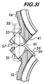
軸の周りでの旋回運動以外のセグメント間の相対運動を防止する突出部対31および33の境界面に、特徴部を組み込むことが望ましいとし得る。図29は、例示的な枢着部の実施形態57を示し、境界曲面39および41(図示せず)は、突出部31の一方の側部に位置決めされた突出リブ59と、突出部の他方の側部に凹部61とを有する。使用時には、図30および図31に示すように、セグメント12および14は、一方のセグメントの突出リブ59が他方のセグメントの凹部61内に嵌合するように、およびその逆となるように、位置合わせされる。リブと凹部との相互作用は、枢着部におけるセグメントの相対的な軸方向運動を防止し、それにより、それら相互の整列を維持する。
It may be desirable to incorporate features at the interface of protrusion pairs 31 and 33 that prevent relative motion between segments other than pivoting about the axis. FIG. 29 shows an exemplary
図32、図33および図34に示す別の例示的な枢着部63では、突出部31および33の境界曲面39および41は少なくとも1つ、好ましくは複数の歯65を有し、それら歯は、セグメントが旋回運動を行う最中に互いにかみ合って、セグメントの互いに対する横移動を防止する。この例では、歯65はギア歯である。図33は、閉鎖構成にあるセグメント12および14を示す;図34は、開放構成にあるセグメントを示す。
In another
図35、図36および図37に示すさらに別の枢着部の実施形態67では、スプライン69が、1つまたは複数の歯を含み、それらスプラインは、突出部31および33の境界面39および41に関連付けられる。スプライン69は、ギア歯と同様に互いにかみ合い、継手セグメント間の横移動を防止する。図36は、閉鎖構成にあるセグメント12および14を示し;図37は、開放構成にあるセグメントを示す。
In yet another pivot embodiment 67 shown in FIGS. 35, 36 and 37, the
図38〜41に示すように、別の枢着部の実施形態71は、一方のセグメント(14)の突出部33に取り付けられた舌部73を有する。舌部73は、他方のセグメント(12)の突出部31のスロット31a内に収容されて、セグメント間の相対的な軸方向運動を防止する。舌部73はスロット31aと係合して、継手セグメント間の横移動を防止する。舌部73は、締結具35を収容するように分割されてもよいことに留意されたい。図40は、閉鎖構成にあるセグメント12および14を示し;図41は、開放構成にあるセグメントを示す。
As shown in FIGS. 38-41, another
図17〜33に示す様々な枢着部の実施形態は、de Raymondらへの米国特許第4,702,499号明細書に詳細に開示されており、この文献全体を参照により本書に組み込む。セグメントを接合する枢着部は、継手に固定されているセグメントが回転する運動中心を有し得ることに留意されたい。例えば、伝統的なヒンジ、例えば図1に示すほぞ継ヒンジは、軸21によって示す固定した運動中心を有する。しかしながら、本発明はまた、瞬間的な運動中心が固定されずに、セグメントが互いに旋回すると移動する枢着部を包含する。本書では、そのような枢着部を図23〜25に示し、これら図面は、軸37のシフトによる瞬間的な運動中心の移動を示す。
Various pivotal embodiments shown in FIGS. 17-33 are disclosed in detail in US Pat. No. 4,702,499 to de Raymond et al., Which is incorporated herein by reference in its entirety. Note that the pivot joint joining the segments may have a center of motion about which the segments secured to the joint rotate. For example, a traditional hinge, such as the mortise hinge shown in FIG. 1, has a fixed center of motion indicated by a
再度図1を参照すると、枢着部13に対向する端部75におけるセグメント12および14の接続は、接続部材18によって達成される。この実施形態では、接続部材は突出部20を含み、これら突出部は、セグメントの端部から外向きに延在する。突出部20はアパーチャ22を有し、これらアパーチャは、ナット26と協働するボルト24などの締結具を収容するように適合されている。締結具は、調整可能に締め付けることができ、かつ、締め付けると、突出部20と協働して、セグメント12および14を中心空間16に近づける。
Referring back to FIG. 1, the connection of the
各セグメントは一対のアーチ状面28を有する。面28は、互いに離間して位置決めされ、かつ中心空間16に対面する。アーチ状面は、突出部20を接続する締結具が締められてセグメントを互いに近づけると、管要素30(図4参照)に係合して保持する。アーチ状面は、管要素、プレーンエンドの管要素、フレアエンドの管要素、または肩部もしくは肩部とビードとを有する管端部にある円周溝に係合し得る。アーチ状面28は、枢着部13を有する端部11に隣接して位置決めされたノッチ87を有し得る。ノッチ87は半径方向のクリアランスを提供し、それにより、セグメントを中心空間16に近づけ、管要素30を係合させて接合部を生じる前に、管要素をセグメント12と14との間に挿入できる。
Each segment has a pair of arcuate surfaces 28. The
各セグメントはまた、少なくとも1つ、好ましくは複数の反作用面32を有する。反作用面32は接続部材18に位置決めされ得る。図1に示す実施形態では、2つの反作用面32が各突出部20に位置決めされる。反作用面は、突出部に対して角度をなして方向付けられ、かつ約30°〜約60°の方向付け角34を有してもよく、および中心空間16に対面するように傾斜している。以下説明するように、約45°の方向付け角が好ましい。
Each segment also has at least one, preferably a plurality of reaction surfaces 32. The
継手10は、枢着部13に対向してセグメント12と14との間に位置決めされた把持体36も含む。把持体は、一対の把持面40を有する(1つのみを示す)。アーチ状面28と同様に、把持面は、離間して位置決めされ、かつ中心空間16に対面している。把持体は、セグメント12および14の突出部20にある反作用面32に対面して位置決めされた一対の接触面42(1つのみを示す)を有する。接触面はまた、突出部に対して角度をなして方向付けられており、かつ約30°〜約60°の方向付け角44を有し得る。以下説明するように、約45°の方向付け角が好ましい。好ましくは、方向付け角34および44は、相互補完的である、つまり、ほぼ同じ角度での向きを有する。
The joint 10 also includes a
継手10を組み立てると、セグメント12および14および把持体36によって、中心空間16内にシール46が収容される。シール46によって、継手10は管端部間に液密接合を確実にもたらす。シール46のサイズは、変形されていない状態では、その外周48が、継手を分解することなく中心空間16に管要素を挿入できるように十分離間させてセグメント12および14および把持体36を支持するようなサイズである。
When the joint 10 is assembled, the
図2〜4を参照して継手の動作を説明する。図2は、予め組み立てられた状態において開放構成で設置準備が整っている、工場から受け取った継手10を示す。この構成では、締結具24はまだ締められておらず、それにより、セグメント12および14および把持体36を中心空間16から半径方向外向きに位置決めして、管要素(明確にするために図示せず)を中心空間に挿入できるようにしている。上述の通り、シール46のサイズは、セグメントおよび把持体を半径方向外向きに保持して、管挿入を容易にするようなサイズである。管要素は、挿入されると、シール46と係合され、継手に液密性をもたらす。次いで、ボルト24およびナット26が締められ、セグメント12および14を互いの方へおよび中心空間16の方へ近づけ、図3および図4に示すような閉鎖構成になるようにする。セグメントが動くと、アーチ状面28は管要素の外表面と係合して、それらを継手内に保持する。図3および図4に比較によって示すように、セグメント12および14が互いの方へ動くことによって、把持体36を、中心空間16の方へ内向きに、セグメントの動きに実質的に垂直な方向に動かす。これにより、把持体36にある把持面40も、管要素の外表面に係合できるようになる。把持体の接触面42と突出部20の反作用面32との相互作用によって、中心空間16の方への把持体の動きが生じる。接触面および反作用面の角度での向き44および34(図1参照)により、それぞれ、面間の力を、中心空間の方へ向けられる成分に分解できるようにする。接触面において適用されるこの力によって、把持体は中心空間の方へ動く。上述の通り、反作用面および接触面の双方に対して、約45°の方向付け角が好ましい。
The operation of the joint will be described with reference to FIGS. FIG. 2 shows the fitting 10 received from the factory, ready for installation in an open configuration in a pre-assembled state. In this configuration, the
図2に示すように、把持体36の端面79とセグメント12および14の肩部81との間には複数の間隙77がある。間隙77は、把持体とセグメントとの間の相対運動を可能にする。
As shown in FIG. 2, there are a plurality of gaps 77 between the
突出部20の反作用面32を位置決めし、かつ接触面42を中心空間16から実質的に半径方向外向きに突出させて、接触面と反作用面との間の境界面が、接続部材18(この例では突出部20)を互いに接合する締結具(ボルト24、ナット26)に近くなることが好都合である。シール46に作用する継手10内の内圧は、セグメント12および14および把持体36を中心空間から離すように押し進める。継手内で把持体に加えられる力は、接触面42と反作用面32との間の境界面においてセグメントに伝達される。接触面42は、角度での向きゆえに、楔のように振る舞い、かつ突出部20を離すように押し進める傾向がある。突出部を接合する締結具の近くに境界面を配置することによって、境界面が締結具から離れていた場合よりも突出部の分離は小さい。接触面−反作用面の境界面を好都合に位置決めすることにより、セグメントの分離を最小限にし、かつ漏れのない状態で継手がより高い圧力に耐えることができるようにする。さらに、セグメントと締結具近くの把持体との間に反作用の力を与えることによって、把持体によるセグメントの歪みが減少し、かつ継手はその丸みを帯びた形状をより良好に維持する。
The
図5は、本発明による継手の例示的な別の実施形態83を示す。この実施形態では、把持体36の接触面42は、凸形状を有する。これにより、それら接触面は、セグメント12および14が互いの方に近づくと、接線方向に反作用面32と係合して、中心空間の方へ向かう把持体36の動きを生じる反作用の力を生じさせることができる。反作用面32は、角度を付けて方向付けられる。図6は、別の例示的な継手の実施形態85を示し、反作用面32は凸形状を有し、かつ接触面42は、角度を付けて方向付けられている。これも同様に、反作用面と接触面との間の接線方向の係合を可能にして、反作用の力を生じ、これにより、セグメント12および14が互いに近づくときに中心空間の方へ向かう把持体36の運動を生じる。
FIG. 5 shows another exemplary embodiment 83 of the joint according to the invention. In this embodiment, the
図7は、本発明による別の例示的な継手の実施形態50の分解等角図を示す。継手50は、一方の端部において枢着部23によって、および他方の端部において、接続部材18と協働するねじ締結具58によって接合されるセグメント12および14を有する。既に説明した継手の実施形態のように、任意のタイプの枢着部が実現可能であることに留意されたい。各セグメントは、管要素を係合するアーチ状面28を有する。継手50は、セグメント間に位置決めされかつ枢着部23に対向する把持体36を有する。把持体は、対向する側面に位置決めされた4つの接触面52と、離間して位置決めされかつ中心空間16に対面する2つの把持面40とを有する。ここでも、この例では、接触面は、接続部材18に対して角度をなして方向付けられ、かつ接続部材18に位置決めされた反作用面54と境界を形成する。接触面の方向付け角56は、この継手設計では、約30°〜約60°が好都合である。図10に示すように、反作用面54の方向付け角は、接触面52の方向付け角とほぼ同じであることが好ましい。
FIG. 7 shows an exploded isometric view of another exemplary
図8aおよび図8bに示すように、接触面52および反作用面54の一方または双方は、凸形状を有し得る。そのような形状は、把持体36およびセグメント12および14によって大きな圧縮力が管要素に加えられるときに好都合であることが分かっている。接触面52および反作用面54のいずれかまたは双方の凸形状は、それら面間の反作用点を、面の端部から離し、より把持体36の中心の方へ動かす。
As shown in FIGS. 8a and 8b, one or both of the
継手50の動作は、上述の継手10の動作と同様である。図8に示すように、締結具58を締める前、セグメント12および14と把持体36は、中心空間16から外側に離間しており、管要素を中心空間に挿入できるようにする。図9に示すような締結具の締め付けは、セグメント12および14を互いにおよび中心空間の方に近づけ、アーチ状面28が管要素の外表面に係合できるようにする。締結具58が締められると、把持体36の接触面52とセグメント12および14の反作用面54との間の相互作用によって、把持体を中心空間の方へ内向きに強制的に動かすようにさせる。図10に示すように、把持体の内向きの動きによって、その把持面40が管要素30に係合する。既に説明した継手の実施形態と同様に、シール46は、セグメント12および14と把持体36との間に収容される。図8に示すように、シール46の外周48のサイズは、変形していないときは、セグメントおよび把持体を、図8に示すような継手50が開放構成にあるときに、中心空間に管要素30を挿入できるように中心空間から十分離間させて支持するようなサイズである。図9に示すように、継手が閉鎖構成にあるとき、シール46はセグメントおよび把持体によって管要素に圧縮され、かつ液密接合を確実にする。
The operation of the joint 50 is the same as the operation of the joint 10 described above. As shown in FIG. 8, before tightening the
図11は、本発明による別の継手の実施形態60の分解図を示す。継手60は継手セグメント12および14を含む。セグメントは、対面して配置され、かつ一方の端部においては枢着部23によって、および対向端部においては接続部材18によって接合される。この実施形態では、既に述べた実施形態のように、接続部材は、外向きに延出する突出部20を含み、調整可能に締め付けることができる締結具58を収容する。締結具を締めることによって、継手セグメント12および14を互いにおよび中心空間16の方に近づける。
FIG. 11 shows an exploded view of another
各セグメントは、互いに離間して位置決めされた、内側を向くアーチ状面28を有する。アーチ状面は、各セグメントの端部間の位置を占有する。反作用面32は、枢着部23に対向する各継手セグメント12および14の端部に、離間して位置決めされる。反作用面32は、突出部20とアーチ状面28との間に位置決めされ、かつ中心空間16の方に向かって内側に対面している。アーチ状面32は、セグメントの周りで接線方向に延在する。反作用面は、以下説明するように、角度をなして方向付けられてもよい。
Each segment has an inwardly facing
セグメント12と14との間で接続部材18に隣接して把持体36が位置決めされる。把持体は、離間して配置された、内側を向く把持面40を有する。好ましくは、図14から最もよく分かるように、継手が組み立てられると、把持面40は、各アーチ状面28と位置合わせされる。再度図11を参照すると、把持体は、離間して接触面42を有する。接触面42は、中心空間16から外側を向き、かつセグメント12および14上の各反作用面32に係合する。把持体上の接触面はセグメント上の反作用面と協働し、例えば、締結具58を締め付けることによってセグメントが互いの方に近づくと、以下さらに説明するように、把持体は、半径方向に内側に動かされる。
A gripping
シール46が継手セグメント12および14と把持体36との間に位置決めされる。セグメントおよび把持体の双方とも、それぞれチャネル62および64を有する(図12参照)。チャネル62は、アーチ状面28間に位置決めされ、およびチャネル64は把持面40間に位置決めされる。チャネル62および64はシール46を受けとめる。シール46の内周66は、内側を向くシール面68および70を有し、それらは、継手によって接合された管要素に係合して、液密シールを形成する。シール46のサイズは、変形されていない状態において、その外周72が、継手が図12に示すような開放構成にあるときに管要素を中心空間16に挿入するのに十分な程度離間してセグメント12および14および把持体36を支持するようなサイズにされている。好ましくは、シールは、接続部材18を調整可能に締め付けることによって継手セグメントを互いの方に近づけると変形するEPDMエラストマーなどの弾性かつ弾力性のある材料で形成されたリングである。
A
図12は、その予め組み立てられた状態において、開放構成にあり、すぐ使える状態である管継手60を示す。管要素を端と端で接続する液密接合を生じるために、図12Aに示すように、管要素30を封止部材46に挿入して、セグメントが、管要素の対面する端部部分をまたぐようにする。管要素を、管要素の外表面にある溝74がセグメントのアーチ状面28および把持体36の把持面40と位置合わせされるまで挿入する。適切な深さに管要素を挿入することは、シール面68と70との間で封止部材に位置決めされた管ストッパ76によって容易にされ得る。管ストッパは内向きに突出して管要素の端部と係合し、挿入深さを所望通りに制限する。
FIG. 12 shows the pipe joint 60 in its pre-assembled state, in an open configuration and ready for use. To create a fluid tight joint that connects the tube elements end to end, as shown in FIG. 12A, the
図12および図13は、管要素30が挿入された状態の継手60の断面図を示す。セグメント12および14の反作用面32が把持体36の接触面42に係合していることに注目する。反作用面は、角度をなして方向付けられているため、締結具58が締め付けられると、セグメント12および14が互いの方に近づいて、図13に示すような閉鎖構成になり、把持体36が半径方向内側に動くため、図13Aに示すように把持体の把持面40が管要素30の溝74を係合して把持する。セグメント12および14が互いの方に近づく動きによってまた、図14に示すように各セグメントのアーチ状面28が溝にも係合してそれを把持するようにする。それゆえ、管要素は、端と端で固定される。封止部材は半径方向内側に変形され、シール面68および70が管要素の外表面にさらに係合するようにする。この構成によって、比較的剛性の接合を生じる。あるいは、アーチ状面の動きが制限されており、溝の床に係合してクランプしない場合には、より可撓性の接合を生じることができる。このために、反作用面および接触面の範囲または長さによって把持体の移動距離が制限される。中心空間へのセグメントのアーチ状面の動きを制限することは、好ましくは、接続部材18が接触することによってセグメントの動きを制限することによって制御される。
12 and 13 show cross-sectional views of the joint 60 with the
図14に示すように、セグメント12および14の反作用面32、および把持体36の接触面42は共通の方向付け角78を有し、この方向付け角は、接続部材18に対して、特に、部材18間の境界面80に対して測定される。約30°〜約60°の方向付け角78が現実的であり、いくつかの適用におけるこの実施形態には約45°の方向付け角が好都合である。
As shown in FIG. 14, the reaction surfaces 32 of the
図15は、本発明による別の継手の実施形態60aの分解図を示す。継手60aは、継手セグメント12および14を含む。これらセグメントは、向かい合って配置され、かつ一方の端部において枢着部23によって、および対向端部において接続部材18によって接合される。この実施形態では、上述した実施形態と同様に、接続部材は、外向きに延出する突出部20を含み、この突出部は締結具58を受け入れ、締結具は調整可能に締め付けることができる。締結具を締め付けることによって、継手セグメント12および14を互いにおよび中心空間16に近づける。
FIG. 15 shows an exploded view of another coupling embodiment 60a according to the present invention. Joint 60a includes
各セグメントは、互いに離間して位置決めされた、内側を向くアーチ状面28を有する。アーチ状面は、各セグメントの端部間の位置を占める。反作用面32は、枢着部23に隣接する各継手セグメント12および14の端部において離間して位置決めされる(反作用面が接続部材18に隣接する実施形態60とは異なる)。反作用面32は、中心空間16の方に向かって内側に面しており、かつセグメントの周りで接線方向に延在する。反作用面は、実施形態60に関して上述したように、角度をなして方向付けられている。
Each segment has an inwardly facing
把持体36が、枢着部23に隣接してセグメント12と14との間に位置決めされる(把持体が接続部材18に隣接する実施形態60とは異なる)。把持体は、離間して配置された、内側を向く把持面40を有する。好ましくは、把持面40は、継手が組み立てられるときに各アーチ状面28と位置合わせされる。把持体36は、離間している接触面42を有する。接触面42は、中心空間16から外向きに面し、かつ図16および図17に示すように、セグメント12および14の各反作用面32に係合する。把持体の接触面はセグメントの反作用面と協働し、例えば、締結具58を締め付けることによってセグメントが互いに近づくと、以下さらに説明するように、把持体は、半径方向内側に動かされる。
A gripping
シール46が継手セグメント12および14と把持体36との間に位置決めされる。セグメントおよび把持体の双方とも、それぞれチャネル62および64を有する(図15参照)。チャネル62はアーチ状面28間に位置決めされ、およびチャネル64は把持面40間に位置決めされる。チャネル62および64はシール46を受けとめる。シール46の内周66は、内側を向くシール面68および70を有し、それらシール面は、継手によって接合された管要素に係合して、液密シールを形成する。シール46のサイズは、変形されていない状態において、その外周72が、セグメント12および14および把持体36を、図16に示すように継手が開放構成にあるときに中心空間16に管要素を挿入するのに十分な程度離間して支持するようなサイズにされている。好ましくは、シールは、接続部材18を調整可能に締め付けることによって継手セグメントが互いに近づくと変形するEPDMエラストマーなどの弾性かつ弾力性のある材料で形成されたリングである。
A
図16は、その予め組み立てられた状態において、開放構成にあり、使える状態にある管継手60aを示す。管要素を端と端で接続する液密接合を生じるために、管要素30を封止部材46に挿入するので、セグメントは、管要素の対面する端部部分をまたぐ。管要素を、管要素の外表面にある溝(図示せず)がセグメントのアーチ状面28および把持体36の把持面40と位置合わせされるまで、挿入する(図15参照)。管要素を適切な深さまで挿入することは、図15および図16に示すようなシール面68と70との間で封止部材に位置決めされた管ストッパ76によって容易にされ得る。管ストッパは、内向きに突出して管要素の端部に係合し、かつ挿入深さを所望通りに制限する。
FIG. 16 shows the pipe joint 60a in its pre-assembled state, in an open configuration and ready for use. Since the
図16および図17は、管要素30が挿入された状態にある継手60aの断面図を示す。セグメント12および14の反作用面32が把持体36の接触面42に係合していることに注目する。反作用面は、角度をなして方向付けられているため、締結具58が締められると、セグメント12および14を互いに近づけ、図17に示すような閉鎖構成になり、把持体36は半径方向内向きに動かされるため、把持体の把持面40が管要素30の溝に係合して把持する。セグメント12および14が互いの方に近づく動きによってまた、各セグメントのアーチ状面28が溝にも係合してそれを把持するようにする。それゆえ、管要素は、端と端で固定される。封止部材は半径方向内向きに変形され、シール面68および70(図15参照)が管要素の外表面とさらに係合するようにする。
16 and 17 show cross-sectional views of the joint 60a with the
図18および図19は、一方の端部において枢着部23によって接合されかつ枢着部に対向するセグメント間に把持体36が位置決めされたセグメント12および14を含む別の継手の実施形態82を示す。継手82は、上述の継手の実施形態と同様であるが、中心空間16に面してセグメント12および14に位置決めされたアーチ状面28の曲率半径84が、管要素の外表面に溝がもしある場合には溝を除いて、管要素30の外表面88の曲率半径86よりも大きいことが異なる。アーチ状面28および管要素30の曲率半径の関係を図18に示す。この図は、管要素を受け取って接合部を形成できる準備ができている、開放構成にある継手82を示す。図19は、閉鎖構成にある継手82を示し、管要素30が中心空間16に挿入され、かつ締結具58が締め付けられており、各セグメントの接続部材18と協働してセグメントを互いに近づけ、それにより、アーチ状面と管要素を係合させ、かつ他の実施形態に関して上述したように接触面と反作用面との相互作用によって把持体36を中心空間の方へ押し進めている。把持体36の把持面40は、図18および図19に比較によって示すように管要素と係合状態となり、およびセグメント12および14は、それらのアーチ状面と管要素とが接触すると変形して、図19に示すように、アーチ状面28の曲率半径84が小さくなって、それらと管要素との間の接触線90に沿って管要素の曲率半径に一致するようになる。アーチ状面の曲率半径が大きいと、図18に示すように、継手が開放構成にあるときのクリアランスが大きくなり、それにより、継手へ管要素を挿入することが容易になる。変形可能な管継手が米国特許第7,086,131号明細書および米国特許第7,712,796号明細書に説明されており、それら双方とも、参照により本書に組み込む。
18 and 19 show another
本発明による継手は、手工具を使用して、予め組み立てられた状態から設置できるようにする移動把持体を使用することによって利点を得る。可動把持体は、セグメントを接合させかつ管要素を把持して液密接合を生じるために必要なトルクを小さくする。さらに、3つの構成要素、すなわち、把持体の把持面および2つのセグメントのアーチ状面を管要素に係合させることによって、より多くの構成要素が存在するときよりも剛性の継手をもたらすことが観察されている。この剛性の向上は、管要素および継手の製造上の公差によるものであると考えられ、4つ以上の構成要素が、同じ係合の程度で確実に管要素に接触するようにすることを困難にする。 The joint according to the invention gains advantages by using a moving grip that allows hand tools to be installed from a pre-assembled state. The movable gripper reduces the torque required to join the segments and grip the tube element to produce a fluid tight joint. Furthermore, engaging the three components, namely the gripping surface of the gripping body and the arcuate surface of the two segments, with the tube element can result in a more rigid joint than when more components are present. Has been observed. This increase in stiffness is believed to be due to manufacturing tolerances in the pipe elements and fittings, making it difficult to ensure that four or more components contact the pipe elements with the same degree of engagement. To.
Claims (41)
前記管要素を収容するための中心空間を取り囲む、端と端で接続された一対のセグメントであって、各前記セグメントが、離間して位置決めされた一対のアーチ状面を有し、前記アーチ状面が前記中心空間に対面しておりかつ前記管要素と係合し得る、一対のセグメントと、
前記セグメントの一方の端部に位置決めされた枢着部であって、前記セグメントを互いに旋回可能に接続する枢着部と、
前記枢着部に対向する端部にある前記セグメントの各々に位置決めされた接続部材であって、前記セグメントを互いに近づけるために調整可能に締め付けることができる接続部材と、
前記セグメントの各々に位置決めされた少なくとも1つの反作用面であって、前記中心空間の方に面する反作用面と、
前記セグメント間に位置決めされた少なくとも1つの把持体であって、離間して位置決めされた一対の把持面を有し、かつ前記中心空間に面する把持体;
前記把持体に位置決めされた一対の接触面であって、前記反作用面の一方とそれぞれ対面する接触面と
を含み、および
前記接続部材の調整可能な締め付けによって、前記セグメントを前記枢着部の周りで旋回させ、それにより、前記継手セグメントを近づけて前記アーチ状面を前記管要素と係合させ、前記反作用面と相互作用する前記接触面が、前記少なくとも1つの把持体を前記中心空間の方へ動かして、前記把持面を前記管要素に係合させる、管継手。 A pipe joint for fixing end portions of a pair of pipe elements to each other end to end,
A pair of end-to-end segments surrounding a central space for accommodating the tube element, each segment having a pair of spaced apart arched surfaces, the arched A pair of segments, a surface facing the central space and capable of engaging the tube element;
A pivot part positioned at one end of the segment, the pivot part connecting the segments pivotably to each other;
A connection member positioned on each of the segments at the end opposite the pivotally attached portion, the connection member being adjustable to tighten the segments closer together;
At least one reaction surface positioned on each of the segments, the reaction surface facing towards the central space;
At least one gripping body positioned between the segments, the gripping body having a pair of gripping surfaces positioned apart from each other and facing the central space;
A pair of contact surfaces positioned on the gripping body, each including a contact surface facing one of the reaction surfaces, and adjustable segment tightening of the connecting member around the pivot portion Swiveling so that the joint segment is brought close to engage the arched surface with the tube element and the contact surface interacting with the reaction surface causes the at least one gripper to move towards the central space. A pipe fitting that engages the gripping surface with the pipe element.
前記セグメントの一方から延出する第1の突出部と、
前記第1の突出部に位置決めされた第1のスロットと、
前記第1の突出部に位置決めされた第1の曲面と、
前記セグメントの他方から延出する第2の突出部と、
前記第2の突出部に位置決めされた第2のスロットと、
前記第2の突出部に位置決めされ、かつ前記第1の曲面と境界を形成する第2の曲面と、
前記第1の突出部と前記第2の突出部との間で前記第1および第2のスロットを通って延在する締結具と
を含む、請求項1に記載の管継手。 The pivot part is
A first protrusion extending from one of the segments;
A first slot positioned in the first protrusion;
A first curved surface positioned on the first protrusion;
A second protrusion extending from the other of the segments;
A second slot positioned in the second protrusion;
A second curved surface positioned on the second protrusion and forming a boundary with the first curved surface;
The pipe joint of claim 1, comprising a fastener extending through the first and second slots between the first protrusion and the second protrusion.
前記第2の曲面内に位置決めされた少なくとも1つの凹部であって、前記少なくとも1つの凹部は前記第1のスロットに実質的に平行に向けられており、前記少なくとも1つのリブが前記少なくとも1つの凹部内に収容されている、凹部と
をさらに含む、請求項9に記載の管継手。 At least one rib positioned on the first curved surface, the at least one rib being oriented substantially parallel to the first slot;
At least one recess positioned within the second curved surface, the at least one recess being oriented substantially parallel to the first slot, and wherein the at least one rib is the at least one recess. The pipe joint according to claim 9, further comprising a recess housed in the recess.
前記セグメントの一方から延出する第1の突出部と、
前記第1の突出部に位置決めされた第1のスロットと、
前記第1の突出部に位置決めされた少なくとも第1の歯と、
前記セグメントの他方から延出する第2の突出部と、
前記第2の突出部に位置決めされた第2のスロットと、
前記第2の突出部に位置決めされ、かつ前記第1の歯と境界を形成する少なくとも第2の歯と、
前記第1の突出部と前記第2の突出部との間で前記第1および第2のスロットを通って延在する締結具と
を含む、請求項1に記載の管継手。 The pivot part is
A first protrusion extending from one of the segments;
A first slot positioned in the first protrusion;
At least a first tooth positioned on the first protrusion;
A second protrusion extending from the other of the segments;
A second slot positioned in the second protrusion;
At least a second tooth positioned on the second protrusion and forming a boundary with the first tooth;
The pipe joint of claim 1, comprising a fastener extending through the first and second slots between the first protrusion and the second protrusion.
前記セグメントの一方から延出する第1の突出部;
前記第1の突出部に位置決めされた第1のスロット;
前記セグメントの他方から延出する第2の突出部;
前記第2の突出部に位置決めされ、かつ前記第1の突出部と前記第1のスロット内で境界を形成する舌部;および
前記第1の突出部と前記第2の突出部との間に、および前記第1のスロットおよび前記舌部を通って延在する締結具
を含む、請求項1に記載の管継手。 The pivot part is:
A first protrusion extending from one of the segments;
A first slot positioned in the first protrusion;
A second protrusion extending from the other of the segments;
A tongue positioned on the second protrusion and forming a boundary within the first slot with the first protrusion; and between the first protrusion and the second protrusion And a fastener extending through the first slot and the tongue.
前記セグメントの一方から延出する第1の突出部と、
前記第1の突出部に位置決めされた第1のスロットと、
前記第1の突出部に位置決めされた第1の角度をなして方向付けられた面と、
前記セグメントの他方から延出する第2の突出部と、
前記第2の突出部に位置決めされた第2のスロットと、
前記第2の突出部に位置決めされ、かつ前記第1の角度をなして方向付けられた面と境界を形成し、第2の角度をなして方向付けられた面と、
前記第1の突出部と前記第2の突出部との間で前記第1および第2のスロットを通って延在する締結具と
を含む、請求項1に記載の管継手。 The pivot part is
A first protrusion extending from one of the segments;
A first slot positioned in the first protrusion;
A surface oriented at a first angle positioned in the first protrusion;
A second protrusion extending from the other of the segments;
A second slot positioned in the second protrusion;
A surface positioned at the second protrusion and oriented with the first angle to form a boundary, and a surface oriented with the second angle;
The pipe joint of claim 1, comprising a fastener extending through the first and second slots between the first protrusion and the second protrusion.
前記管要素を収容するための中心空間を取り囲む、端と端で接続された一対のセグメントであって、各前記セグメントが、離間して位置決めされた一対のアーチ状面を有し、前記アーチ状面が前記中心空間に面しかつ前記管要素に係合可能である、一対のセグメントと、
前記セグメントの一方の端部に位置決めされた枢着部であって、前記セグメントを互いに旋回可能に接続する枢着部と、
前記枢着部に対向する端部にある前記セグメントの各々に位置決めされた接続部材であって、前記セグメントを互いに近づけるために調整可能に締め付けることができる接続部材と、
前記セグメントの各々に位置決めされた一対の反作用面であって、前記中心空間の方に面する一対の反作用面と、
前記セグメント間に位置決めされた少なくとも1つの把持体であって、離間して位置決めされかつ前記中心空間に面する一対の把持面を有する把持体と、
前記把持体に位置決めされた第1および第2の対の接触面であって、前記セグメントの前記反作用面の一方とそれぞれ対面する接触面と
を含み、
前記接続部材を調整可能に締め付けることによって、前記枢着部の周りで前記セグメントを旋回させ、それにより、前記継手セグメントを互いに近づけて前記アーチ状面を前記管要素に係合させ、前記反作用面と相互作用する前記接触面が、前記少なくとも1つの把持体を前記中心空間の方へ動かして、前記把持面を前記管要素と係合させる、管継手。 A pipe joint for fixing end portions of a pair of pipe elements to each other end to end,
A pair of end-to-end segments surrounding a central space for accommodating the tube element, each segment having a pair of spaced apart arched surfaces, the arched A pair of segments with a face facing the central space and engageable with the tube element;
A pivot part positioned at one end of the segment, the pivot part connecting the segments pivotably to each other;
A connection member positioned on each of the segments at the end opposite the pivotally attached portion, the connection member being adjustable to tighten the segments closer together;
A pair of reaction surfaces positioned on each of the segments, the pair of reaction surfaces facing the central space;
At least one gripping body positioned between the segments, the gripping body positioned at a distance and having a pair of gripping faces facing the central space;
A first and a second pair of contact surfaces positioned on the gripping body, each contact surface facing one of the reaction surfaces of the segment;
Adjustably tightening the connecting member causes the segment to pivot about the pivot, thereby bringing the joint segments closer together to engage the arched surface with the tube element and the reaction surface A pipe joint, wherein the contact surface interacting with the pipe moves the at least one gripping body towards the central space to engage the gripping face with the pipe element.
前記セグメントの一方から延出する第1の突出部と、
前記第1の突出部に位置決めされた第1のスロットと、
前記第1の突出部に位置決めされた第1の曲面と、
前記セグメントの他方から延出する第2の突出部と、
前記第2の突出部に位置決めされた第2のスロットと、
前記第2の突出部に位置決めされ、前記第1の曲面と境界を形成する第2の曲面と、
前記第1の突出部と前記第2の突出部との間で前記第1および第2のスロットを通って延在する締結具と
を含む、請求項20に記載の管継手。 The pivot part is
A first protrusion extending from one of the segments;
A first slot positioned in the first protrusion;
A first curved surface positioned on the first protrusion;
A second protrusion extending from the other of the segments;
A second slot positioned in the second protrusion;
A second curved surface positioned on the second protrusion and forming a boundary with the first curved surface;
21. The pipe fitting of claim 20, including a fastener extending through the first and second slots between the first protrusion and the second protrusion.
前記第2の曲面内に位置決めされた少なくとも1つの凹部であって、前記少なくとも1つの凹は前記第1のスロットに実質的に平行に向けられており、前記少なくとも1つのリブが前記少なくとも1つの凹部内に収容される、少なくとも1つの凹部
をさらに含む、請求項28に記載の管継手。 At least one rib positioned on the first curved surface, the at least one rib being oriented substantially parallel to the first slot;
At least one recess positioned in the second curved surface, the at least one recess being oriented substantially parallel to the first slot, and wherein the at least one rib is the at least one recess. 30. The fitting according to claim 28, further comprising at least one recess housed in the recess.
前記セグメントの一方から延出する第1の突出部と、
前記第1の突出部に位置決めされた第1のスロットと、
前記第1の突出部に位置決めされた少なくとも第1の歯と、
前記セグメントの他方から延出する第2の突出部と、
前記第2の突出部に位置決めされた第2のスロットと、
前記第2の突出部に位置決めされ、かつ前記第1の歯と境界を形成する少なくとも第2の歯と、
前記第1の突出部と前記第2の突出部との間で前記第1および第2のスロットを通って延在する締結具と
を含む、請求項20に記載の管継手。 The pivot part is
A first protrusion extending from one of the segments;
A first slot positioned in the first protrusion;
At least a first tooth positioned on the first protrusion;
A second protrusion extending from the other of the segments;
A second slot positioned in the second protrusion;
At least a second tooth positioned on the second protrusion and forming a boundary with the first tooth;
21. The pipe fitting of claim 20, including a fastener extending through the first and second slots between the first protrusion and the second protrusion.
前記セグメントの一方から延出する第1の突出部と、
前記第1の突出部に位置決めされた第1のスロットと、
前記セグメントの他方から延出する第2の突出部と、
前記第2の突出部に位置決めされ、かつ前記第1の突出部と前記第1のスロット内で境界を形成する舌部と、
前記第1および第2の突出部との間に、および前記第1のスロットおよび前記舌部を通って延在する、締結具と
を含む、請求項20に記載の管継手。 The pivot part is
A first protrusion extending from one of the segments;
A first slot positioned in the first protrusion;
A second protrusion extending from the other of the segments;
A tongue positioned on the second protrusion and defining a boundary within the first protrusion and the first slot;
21. The fitting according to claim 20, comprising a fastener extending between the first and second protrusions and through the first slot and tongue.
前記セグメントの一方から延出する第1の突出部と、
前記第1の突出部に位置決めされた第1のスロットと、
前記第1の突出部に位置決めされた第1の角度をなして方向付けられた面;
前記セグメントの他方から延出する第2の突出部と、
前記第2の突出部に位置決めされた第2のスロットと、
前記第2の突出部に位置決めされ、かつ前記第1の角度をなして方向付けられた面と境界を形成し、第2の角度をなして方向付けられた面と、
前記第1の突出部と前記第2の突出部との間で前記第1および第2のスロットを通って延在する締結具と
を含む、請求項20に記載の管継手。 The pivot part is
A first protrusion extending from one of the segments;
A first slot positioned in the first protrusion;
A surface oriented at a first angle positioned at the first protrusion;
A second protrusion extending from the other of the segments;
A second slot positioned in the second protrusion;
A surface positioned at the second protrusion and oriented with the first angle to form a boundary, and a surface oriented with the second angle;
21. The pipe fitting of claim 20, including a fastener extending through the first and second slots between the first protrusion and the second protrusion.
前記継手に前記管要素を挿入するステップと、
前記継手セグメントを旋回軸の周りで旋回させることによって、前記継手セグメントを前記管要素と係合させるステップと、
前記把持体を前記管要素と係合するように動かすステップと
を含む方法。 A method of joining pipe elements end to end using a joint having opposing joint segments and a movable gripper positioned therebetween,
Inserting the tube element into the joint;
Engaging the joint segment with the tube element by pivoting the joint segment about a pivot axis;
Moving the gripping body into engagement with the tube element.
Applications Claiming Priority (3)
| Application Number | Priority Date | Filing Date | Title |
|---|---|---|---|
| US201161471713P | 2011-04-05 | 2011-04-05 | |
| US61/471,713 | 2011-04-05 | ||
| PCT/US2012/032038 WO2012138677A1 (en) | 2011-04-05 | 2012-04-04 | Pivoting pipe coupling having a movable gripping body |
Publications (2)
| Publication Number | Publication Date |
|---|---|
| JP2014513252A true JP2014513252A (en) | 2014-05-29 |
| JP5967729B2 JP5967729B2 (en) | 2016-08-10 |
Family
ID=46965512
Family Applications (1)
| Application Number | Title | Priority Date | Filing Date |
|---|---|---|---|
| JP2014503921A Expired - Fee Related JP5967729B2 (en) | 2011-04-05 | 2012-04-04 | Swivel pipe fitting with movable gripper |
Country Status (13)
| Country | Link |
|---|---|
| US (2) | US8556302B2 (en) |
| EP (1) | EP2694857B1 (en) |
| JP (1) | JP5967729B2 (en) |
| KR (1) | KR101989884B1 (en) |
| CN (1) | CN103270359B (en) |
| AU (1) | AU2012240321B2 (en) |
| BR (1) | BR112013024478A2 (en) |
| CA (1) | CA2832137C (en) |
| ES (1) | ES2556795T3 (en) |
| MX (1) | MX336612B (en) |
| SG (1) | SG193019A1 (en) |
| TW (1) | TWI518275B (en) |
| WO (1) | WO2012138677A1 (en) |
Families Citing this family (119)
| Publication number | Priority date | Publication date | Assignee | Title |
|---|---|---|---|---|
| US7950701B2 (en) * | 2007-05-15 | 2011-05-31 | Victaulic Company | Pipe coupling having movable gripping bodies |
| US8282136B2 (en) | 2008-06-30 | 2012-10-09 | Mueller International, Llc | Slip on groove coupling with multiple sealing gasket |
| USD696751S1 (en) | 2011-10-27 | 2013-12-31 | Mueller International, Llc | Slip-on gasket |
| USD680629S1 (en) | 2011-11-21 | 2013-04-23 | Mueller International, Llc | Slip-on coupling segment |
| USD680630S1 (en) | 2011-11-21 | 2013-04-23 | Mueller International, Llc | Slip-on coupling assembly |
| US9039046B2 (en) | 2012-01-20 | 2015-05-26 | Mueller International, Llc | Coupling with tongue and groove |
| US9500307B2 (en) | 2012-01-20 | 2016-11-22 | Mueller International, Llc | Slip-on coupling gasket |
| US9194516B2 (en) | 2012-01-20 | 2015-11-24 | Mueller International, Llc | Slip-on coupling |
| US9534715B2 (en) | 2012-01-20 | 2017-01-03 | Mueller International, Llc | Coupling gasket with multiple sealing surfaces |
| US9168585B2 (en) | 2012-11-02 | 2015-10-27 | Mueller International, Llc | Coupling with extending parting line |
| US20200137906A9 (en) * | 2012-11-05 | 2020-04-30 | Gui Global Products, Ltd. | Devices and accessories employing a living hinge |
| US9893500B2 (en) | 2012-11-16 | 2018-02-13 | U.S. Well Services, LLC | Switchgear load sharing for oil field equipment |
| US11476781B2 (en) | 2012-11-16 | 2022-10-18 | U.S. Well Services, LLC | Wireline power supply during electric powered fracturing operations |
| US9995218B2 (en) | 2012-11-16 | 2018-06-12 | U.S. Well Services, LLC | Turbine chilling for oil field power generation |
| US11449018B2 (en) | 2012-11-16 | 2022-09-20 | U.S. Well Services, LLC | System and method for parallel power and blackout protection for electric powered hydraulic fracturing |
| US9745840B2 (en) | 2012-11-16 | 2017-08-29 | Us Well Services Llc | Electric powered pump down |
| US10407990B2 (en) | 2012-11-16 | 2019-09-10 | U.S. Well Services, LLC | Slide out pump stand for hydraulic fracturing equipment |
| US10232332B2 (en) | 2012-11-16 | 2019-03-19 | U.S. Well Services, Inc. | Independent control of auger and hopper assembly in electric blender system |
| US10100635B2 (en) * | 2012-12-19 | 2018-10-16 | Exxonmobil Upstream Research Company | Wired and wireless downhole telemetry using a logging tool |
| US20150292319A1 (en) | 2012-12-19 | 2015-10-15 | Exxon-Mobil Upstream Research Company | Telemetry for Wireless Electro-Acoustical Transmission of Data Along a Wellbore |
| US9816373B2 (en) * | 2012-12-19 | 2017-11-14 | Exxonmobil Upstream Research Company | Apparatus and method for relieving annular pressure in a wellbore using a wireless sensor network |
| US9557434B2 (en) | 2012-12-19 | 2017-01-31 | Exxonmobil Upstream Research Company | Apparatus and method for detecting fracture geometry using acoustic telemetry |
| WO2014100276A1 (en) | 2012-12-19 | 2014-06-26 | Exxonmobil Upstream Research Company | Electro-acoustic transmission of data along a wellbore |
| US10480308B2 (en) | 2012-12-19 | 2019-11-19 | Exxonmobil Upstream Research Company | Apparatus and method for monitoring fluid flow in a wellbore using acoustic signals |
| US10578234B2 (en) * | 2013-05-02 | 2020-03-03 | Victaulic Company | Coupling having arcuate stiffness ribs |
| USD755621S1 (en) * | 2013-09-25 | 2016-05-10 | Victaulic Company | Pipe coupling segment |
| USD750957S1 (en) * | 2013-09-25 | 2016-03-08 | Victaulic Company | Pipe coupling segment |
| USD756212S1 (en) * | 2013-09-25 | 2016-05-17 | Victaulic Company | Pipe coupling segment |
| US10132149B2 (en) | 2013-11-26 | 2018-11-20 | Exxonmobil Upstream Research Company | Remotely actuated screenout relief valves and systems and methods including the same |
| EP3039332B1 (en) | 2013-12-23 | 2019-01-16 | Victaulic Company | Split ring coupling |
| US20190331265A1 (en) | 2013-12-23 | 2019-10-31 | Victaulic Company | Split Ring Coupling and Fitting |
| CN104019307A (en) * | 2014-06-16 | 2014-09-03 | 成都力锋清洗机股份有限公司 | Ultrahigh pressure pipe connector safety protection sleeve |
| KR102051990B1 (en) * | 2014-09-11 | 2019-12-04 | 빅톨릭 컴패니 | Coupling and seal |
| US10508536B2 (en) | 2014-09-12 | 2019-12-17 | Exxonmobil Upstream Research Company | Discrete wellbore devices, hydrocarbon wells including a downhole communication network and the discrete wellbore devices and systems and methods including the same |
| CA2908276C (en) | 2014-10-14 | 2022-11-01 | Us Well Services Llc | Parallel power and blackout protection for electric hydraulic fracturing |
| US9863222B2 (en) | 2015-01-19 | 2018-01-09 | Exxonmobil Upstream Research Company | System and method for monitoring fluid flow in a wellbore using acoustic telemetry |
| US10408047B2 (en) * | 2015-01-26 | 2019-09-10 | Exxonmobil Upstream Research Company | Real-time well surveillance using a wireless network and an in-wellbore tool |
| WO2017042874A1 (en) * | 2015-09-08 | 2017-03-16 | 日本管洗工業株式会社 | Pressure pipe connection method and method for constructing pressure pipe with flange |
| US12078110B2 (en) | 2015-11-20 | 2024-09-03 | Us Well Services, Llc | System for gas compression on electric hydraulic fracturing fleets |
| CN108431479B (en) | 2015-12-28 | 2020-11-17 | 维克托里克公司 | Adapter connector |
| US10533688B2 (en) | 2016-05-16 | 2020-01-14 | Victaulic Company | Coupling having tabbed retainer |
| US10605394B2 (en) | 2016-05-16 | 2020-03-31 | Victaulic Company | Fitting having tabbed retainer and observation apertures |
| US10859190B2 (en) | 2016-05-16 | 2020-12-08 | Victaulic Company | Sprung coupling |
| CN105909630A (en) * | 2016-06-06 | 2016-08-31 | 珠海格力电器股份有限公司 | Fixed knot constructs and has its pipeline purifier |
| US10526888B2 (en) | 2016-08-30 | 2020-01-07 | Exxonmobil Upstream Research Company | Downhole multiphase flow sensing methods |
| US10697287B2 (en) | 2016-08-30 | 2020-06-30 | Exxonmobil Upstream Research Company | Plunger lift monitoring via a downhole wireless network field |
| US10465505B2 (en) | 2016-08-30 | 2019-11-05 | Exxonmobil Upstream Research Company | Reservoir formation characterization using a downhole wireless network |
| US10344583B2 (en) | 2016-08-30 | 2019-07-09 | Exxonmobil Upstream Research Company | Acoustic housing for tubulars |
| US10415376B2 (en) | 2016-08-30 | 2019-09-17 | Exxonmobil Upstream Research Company | Dual transducer communications node for downhole acoustic wireless networks and method employing same |
| US10590759B2 (en) | 2016-08-30 | 2020-03-17 | Exxonmobil Upstream Research Company | Zonal isolation devices including sensing and wireless telemetry and methods of utilizing the same |
| US10364669B2 (en) | 2016-08-30 | 2019-07-30 | Exxonmobil Upstream Research Company | Methods of acoustically communicating and wells that utilize the methods |
| US11828172B2 (en) | 2016-08-30 | 2023-11-28 | ExxonMobil Technology and Engineering Company | Communication networks, relay nodes for communication networks, and methods of transmitting data among a plurality of relay nodes |
| USD823443S1 (en) | 2016-09-29 | 2018-07-17 | Victaulic Company | Pipe coupling |
| US11181107B2 (en) | 2016-12-02 | 2021-11-23 | U.S. Well Services, LLC | Constant voltage power distribution system for use with an electric hydraulic fracturing system |
| US11378208B2 (en) | 2016-12-14 | 2022-07-05 | ASC Engineered Solutions, LLC | Pipe couplings |
| PE20191157A1 (en) | 2017-01-19 | 2019-09-09 | Victaulic Co Of America | COMPATIBLE DIRECT-COUPLED SPRINKLER |
| PE20240516A1 (en) * | 2017-01-24 | 2024-03-18 | Victaulic Co Of America | COUPLING AND CIRCUMFERENTIAL GROOVE SHAPE |
| CN110249168B (en) * | 2017-02-02 | 2021-06-29 | 维克托里克公司 | Mechanical Couplings for Mechanical and Structural Fittings |
| JP6429413B2 (en) * | 2017-03-10 | 2018-11-28 | 株式会社Subaru | Image display device |
| US11060646B2 (en) | 2017-04-18 | 2021-07-13 | Cobalt Coupler Systems, LLC | Coupler |
| US10962157B2 (en) | 2017-04-18 | 2021-03-30 | Cobalt Coupler Systems, LLC | Coupler |
| US11560972B2 (en) | 2017-04-18 | 2023-01-24 | Cobalt Coupler Systems, LLC | Oil and gas pipe connector |
| US20180320721A1 (en) * | 2017-05-04 | 2018-11-08 | Fisher Controls International Llc | Apparatus to connect a valve stem to an actuator |
| AU2018277526B2 (en) * | 2017-05-30 | 2023-12-21 | Tyco Fire Products Lp | Pre-assembled pipe coupling with manually manipulatable segments |
| EP3631270B1 (en) * | 2017-05-30 | 2023-09-20 | Tyco Fire Products LP | Pre-assembled pipe coupling with an insertion boundary for axial receipt of pipe ends |
| PE20200051A1 (en) | 2017-06-02 | 2020-01-15 | Victaulic Co Of America | COUPLING HAVING A SEAL WITH RETRACTABLE CENTER LEG |
| MX2020003297A (en) | 2017-10-13 | 2020-07-28 | Exxonmobil Upstream Res Co | Method and system for performing operations with communications. |
| WO2019074656A1 (en) | 2017-10-13 | 2019-04-18 | Exxonmobil Upstream Research Company | Method and system for performing communications using aliasing |
| AU2018347876B2 (en) | 2017-10-13 | 2021-10-07 | Exxonmobil Upstream Research Company | Method and system for performing hydrocarbon operations with mixed communication networks |
| AU2018347466B2 (en) | 2017-10-13 | 2020-12-24 | Exxonmobil Upstream Research Company | Method and system for performing operations using communications |
| US10697288B2 (en) | 2017-10-13 | 2020-06-30 | Exxonmobil Upstream Research Company | Dual transducer communications node including piezo pre-tensioning for acoustic wireless networks and method employing same |
| US10837276B2 (en) | 2017-10-13 | 2020-11-17 | Exxonmobil Upstream Research Company | Method and system for performing wireless ultrasonic communications along a drilling string |
| MX2020007277A (en) | 2017-11-17 | 2020-08-17 | Exxonmobil Upstream Res Co | Method and system for performing wireless ultrasonic communications along tubular members. |
| US12000273B2 (en) | 2017-11-17 | 2024-06-04 | ExxonMobil Technology and Engineering Company | Method and system for performing hydrocarbon operations using communications associated with completions |
| US10690794B2 (en) | 2017-11-17 | 2020-06-23 | Exxonmobil Upstream Research Company | Method and system for performing operations using communications for a hydrocarbon system |
| CA3084596A1 (en) | 2017-12-05 | 2019-06-13 | U.S. Well Services, LLC | Multi-plunger pumps and associated drive systems |
| WO2019113153A1 (en) | 2017-12-05 | 2019-06-13 | U.S. Well Services, Inc. | High horsepower pumping configuration for an electric hydraulic fracturing system |
| US10844708B2 (en) | 2017-12-20 | 2020-11-24 | Exxonmobil Upstream Research Company | Energy efficient method of retrieving wireless networked sensor data |
| CA3086529C (en) | 2017-12-29 | 2022-11-29 | Exxonmobil Upstream Research Company | Methods and systems for monitoring and optimizing reservoir stimulation operations |
| US11156081B2 (en) | 2017-12-29 | 2021-10-26 | Exxonmobil Upstream Research Company | Methods and systems for operating and maintaining a downhole wireless network |
| MX2020008276A (en) | 2018-02-08 | 2020-09-21 | Exxonmobil Upstream Res Co | Methods of network peer identification and self-organization using unique tonal signatures and wells that use the methods. |
| US11268378B2 (en) | 2018-02-09 | 2022-03-08 | Exxonmobil Upstream Research Company | Downhole wireless communication node and sensor/tools interface |
| USD861473S1 (en) | 2018-04-11 | 2019-10-01 | Victaulic Company | Pipe coupling |
| US11211801B2 (en) | 2018-06-15 | 2021-12-28 | U.S. Well Services, LLC | Integrated mobile power unit for hydraulic fracturing |
| US10648270B2 (en) | 2018-09-14 | 2020-05-12 | U.S. Well Services, LLC | Riser assist for wellsites |
| US11448346B2 (en) * | 2018-09-28 | 2022-09-20 | ASC Engineered Solutions, LLC | Pipe coupling |
| CA3115650A1 (en) | 2018-10-09 | 2020-04-23 | U.S. Well Services, LLC | Electric powered hydraulic fracturing pump system with single electric powered multi-plunger pump fracturing trailers, filtration units, and slide out platform |
| CN109442108B (en) | 2018-12-14 | 2024-05-03 | 山东莱德机械有限公司 | Quick-connection clamp |
| US11293280B2 (en) | 2018-12-19 | 2022-04-05 | Exxonmobil Upstream Research Company | Method and system for monitoring post-stimulation operations through acoustic wireless sensor network |
| US11952886B2 (en) | 2018-12-19 | 2024-04-09 | ExxonMobil Technology and Engineering Company | Method and system for monitoring sand production through acoustic wireless sensor network |
| USD897195S1 (en) | 2019-02-28 | 2020-09-29 | Victaulic Company | Ring and gusset coupling |
| US11578577B2 (en) | 2019-03-20 | 2023-02-14 | U.S. Well Services, LLC | Oversized switchgear trailer for electric hydraulic fracturing |
| US11371630B2 (en) * | 2019-03-29 | 2022-06-28 | ASC Engineered Solutions, LLC | Pivot clip |
| US11728709B2 (en) | 2019-05-13 | 2023-08-15 | U.S. Well Services, LLC | Encoderless vector control for VFD in hydraulic fracturing applications |
| KR102098328B1 (en) * | 2019-05-17 | 2020-04-07 | 주식회사 뉴아세아조인트 | Coupling assembly for connecting pipes and manufacturing method of the same |
| CA3143050A1 (en) | 2019-06-10 | 2020-12-17 | U.S. Well Services, LLC | Integrated fuel gas heater for mobile fuel conditioning equipment |
| CN110230735A (en) * | 2019-06-26 | 2019-09-13 | 山东亿佰通机械股份有限公司 | Clipper joint and connector with the clipper joint |
| US10711929B1 (en) * | 2019-06-29 | 2020-07-14 | Shanghai Vision Mechanical Joint Co., Ltd. | Pipe element coupler and coupling method thereof |
| KR102094381B1 (en) * | 2019-07-18 | 2020-03-27 | 주식회사 뉴아세아조인트 | Coupling assembly for connecting pipes and manufacturing method of the same |
| USD941408S1 (en) * | 2019-09-06 | 2022-01-18 | Dylan Jones | Locking barbell collar with side magnets |
| KR20220053674A (en) * | 2019-09-30 | 2022-04-29 | 빅톨릭 컴패니 | outlet coupling |
| US11459863B2 (en) | 2019-10-03 | 2022-10-04 | U.S. Well Services, LLC | Electric powered hydraulic fracturing pump system with single electric powered multi-plunger fracturing pump |
| US11781683B2 (en) * | 2019-11-15 | 2023-10-10 | Victaulic Company | Shrouded coupling |
| US11009162B1 (en) | 2019-12-27 | 2021-05-18 | U.S. Well Services, LLC | System and method for integrated flow supply line |
| US12509974B2 (en) | 2019-12-27 | 2025-12-30 | U.S. Well Services, LLC | Systems and methods for fluid end health monitoring |
| US11885206B2 (en) | 2019-12-30 | 2024-01-30 | U.S. Well Services, LLC | Electric motor driven transportation mechanisms for fracturing blenders |
| US11492886B2 (en) | 2019-12-31 | 2022-11-08 | U.S. Wells Services, LLC | Self-regulating FRAC pump suction stabilizer/dampener |
| CN111188955B (en) * | 2020-02-27 | 2021-08-03 | 玫德集团有限公司 | A tube clip and tube clip assembly that can realize quick connection |
| JP7609989B2 (en) * | 2020-11-06 | 2025-01-07 | ビクターリック カンパニー | Coupling with limited rotation section |
| US12253195B2 (en) | 2020-11-06 | 2025-03-18 | Victaulic Company | Coupling having visual installation indicators |
| USD934515S1 (en) * | 2020-12-09 | 2021-10-26 | Just Fur Love, LLC | Clamp for mounting an animal guard |
| USD943382S1 (en) * | 2020-12-14 | 2022-02-15 | Mark A. Kelley | Six-hole half cylinder clamp |
| US20220325824A1 (en) * | 2021-04-13 | 2022-10-13 | Meter Technology Werks, LLC | Hinge Nut for Meter Coupling Valve |
| US20220341527A1 (en) * | 2021-04-27 | 2022-10-27 | Victaulic Company | Mechanical Outlet |
| CN112984246B (en) * | 2021-04-28 | 2021-07-13 | 山东祺龙海洋石油钢管股份有限公司 | Self-adaptation clamp connector clamping device |
| AU2022410587A1 (en) | 2021-12-17 | 2024-06-20 | Lubrizol Advanced Materials, Inc. | Pipe apparatus, coupling devices, and methods |
| US12449071B2 (en) * | 2022-05-25 | 2025-10-21 | Mueller International, Llc | Compression fitting |
| US12181083B2 (en) | 2022-07-21 | 2024-12-31 | Applied System Technologies, Inc. | Pipe coupling |
| CN115539724B (en) * | 2022-09-17 | 2026-01-09 | 上海威逊机械连接件有限公司 | A quick-install pipe fitting |
Citations (6)
| Publication number | Priority date | Publication date | Assignee | Title |
|---|---|---|---|---|
| US4408788A (en) * | 1981-09-23 | 1983-10-11 | Grinnell Fire Protection Systems Company, Inc. | Hingeable split pipe collar |
| US4702499A (en) * | 1986-10-21 | 1987-10-27 | Victaulic Company Of America | Hingeable segmented pipe couplings |
| GB2349189A (en) * | 1999-02-12 | 2000-10-25 | Mining Supplies Australia Pty | Pipe collar |
| US6533333B1 (en) * | 1998-08-24 | 2003-03-18 | Central Sprinkler Corporation | Hinged mechanical couplings with interfitting ends |
| WO2005114023A2 (en) * | 2004-05-14 | 2005-12-01 | Victaulic Company | Deformable mechanical pipe coupling |
| WO2008144332A1 (en) * | 2007-05-15 | 2008-11-27 | Victaulic Company | Pipe coupling having movable gripping bodies |
Family Cites Families (64)
| Publication number | Priority date | Publication date | Assignee | Title |
|---|---|---|---|---|
| US591796A (en) | 1897-10-12 | Chusetts | ||
| US711946A (en) | 1899-12-06 | 1902-10-28 | Sanitary Coupling Company | Water-closet. |
| US1004634A (en) | 1909-10-06 | 1911-10-03 | Safety Car Heating & Lighting | Hose appliance. |
| US1662954A (en) | 1922-07-10 | 1928-03-20 | Broido Anna G Freedman | Pipe joint |
| US1532596A (en) | 1923-07-18 | 1925-04-07 | Peter Madsen | Hose clamp |
| US1831641A (en) | 1927-07-20 | 1931-11-10 | M B Skinner Co | Pipe clamp |
| US1791810A (en) | 1927-08-11 | 1931-02-10 | Furman Eugene Clay | Fluid-tight joint |
| US1821863A (en) | 1929-11-01 | 1931-09-01 | Wylie G Wilson | Fluid tight joint and method of making |
| US1930194A (en) | 1930-06-28 | 1933-10-10 | Stephen V Dillon | Pipe coupling |
| US2028182A (en) | 1932-04-28 | 1936-01-21 | Jr Ferd Barnickol | Coupling |
| US2005056A (en) | 1934-05-26 | 1935-06-18 | Gustin Bacon Mfg Co | Pipe coupling |
| US2182797A (en) | 1938-03-15 | 1939-12-12 | Stephen V Dillon | Gripping and coupling means |
| US2165920A (en) | 1938-03-17 | 1939-07-11 | Us Stoneware Co | Pipe joint |
| US2377510A (en) * | 1942-09-26 | 1945-06-05 | Dresser Ind | Hinged self-sealing coupling |
| US2512741A (en) | 1945-04-17 | 1950-06-27 | Howard W Goodall | Hose coupling |
| US2473046A (en) | 1945-11-29 | 1949-06-14 | Jr Charles Adams | Pipe clamp |
| US3078108A (en) | 1959-08-05 | 1963-02-19 | Joseph B Smith | Split coupling |
| US3003793A (en) | 1960-04-14 | 1961-10-10 | Edmund W Pitt | Longitudinally divided sleeved pipe coupling |
| US3116078A (en) | 1961-07-18 | 1963-12-31 | Bernard F Scherer | Coupling having annularly arranged u-shaped gripping members retained against movement in sleeve |
| US3351352A (en) | 1962-02-27 | 1967-11-07 | Victaulic Co Of America | Gasket for pipe joint |
| US3249371A (en) | 1963-10-14 | 1966-05-03 | Imp Eastman Corp | Full grip clamp |
| US3329446A (en) | 1966-08-18 | 1967-07-04 | Automatic Sprinkler Corp | Pipe coupling |
| US3479066A (en) | 1967-07-03 | 1969-11-18 | Morris Gittleman | Pipe coupling |
| US4417755A (en) | 1974-10-07 | 1983-11-29 | Familian Corp. | Pipe coupling |
| US4018979A (en) | 1975-12-22 | 1977-04-19 | Sunbank Electronics, Inc. | Split shell connector accessory for electrical cables |
| JPS57161391A (en) | 1981-03-26 | 1982-10-04 | Isuzu Fishing Reel Mfg | Tube body connector |
| US4611839A (en) | 1983-07-12 | 1986-09-16 | Victaulic Company Of America | Self-adjusting pipe clamp and coupling |
| US4639020A (en) | 1983-07-12 | 1987-01-27 | Victaulic Company Of America | Self-adjusting pipe clamp and coupling |
| US4611835A (en) | 1984-02-17 | 1986-09-16 | Familian Corp. | Pipe coupling |
| DE3524621A1 (en) | 1985-07-10 | 1987-01-15 | Rasmussen Gmbh | PIPE COUPLING |
| US4838584A (en) | 1987-09-24 | 1989-06-13 | The United States Of America As Represented By The Secretary Of The Air Force | Quick disconnect duct coupler |
| GB8724335D0 (en) | 1987-10-16 | 1987-11-18 | Victaulic Plc | Pipe joint & coupling |
| ATE86725T1 (en) | 1988-07-16 | 1993-03-15 | Peart E & Co Ltd | A PIPE CONNECTION OR CLOSING DEVICE. |
| US5058931A (en) | 1988-11-28 | 1991-10-22 | Gustin-Bacon Division, A Division Of Tyler Pipe | Clamp with teeth for grooved pipes |
| GB8830202D0 (en) | 1988-12-23 | 1989-02-22 | Parkfield Group Plc | Pipe coupling |
| GB2240600B (en) | 1990-02-02 | 1993-04-21 | Peart E & Co Ltd | A pipe repair or jointing collar |
| US5018768A (en) | 1990-07-19 | 1991-05-28 | Quikcoup, Incorporated | Pipe coupling hinge |
| GB2253451B (en) | 1991-02-23 | 1995-01-11 | Glynwed Consumer & Building | Pipe coupling |
| US5161836A (en) | 1992-01-23 | 1992-11-10 | Mckinnon Robert M | Pipe connecting apparatus |
| US5286064A (en) | 1992-04-02 | 1994-02-15 | Bridges Donald Y | Sealing plate for a pipe coupling |
| US5605537A (en) | 1994-08-08 | 1997-02-25 | Ivey; Jack L. | Endoscopic device |
| US5605357A (en) | 1995-06-05 | 1997-02-25 | M&Fc Holding Co. | Pipe collar |
| US5769467A (en) | 1995-10-10 | 1998-06-23 | Bridges; Donald Y. | Pipe couplings for misaligned or out-of-round pipes and expanding/contracting pipes |
| GB2310903B (en) | 1996-03-05 | 1999-12-15 | Avk Mfg Ltd | A pipe repair or jointing collar |
| US5758907A (en) | 1996-07-26 | 1998-06-02 | Victaulic Company Of America | Mis-adjustment limiting segmented pipe coupling |
| US5722701A (en) | 1996-12-04 | 1998-03-03 | Choi; Sang-Min | Method and assembly for joining pipes |
| DE19802676C1 (en) | 1998-01-24 | 1999-05-06 | Rasmussen Gmbh | Clamp on pipe coupling |
| DE19901663C2 (en) | 1999-01-18 | 2001-02-22 | Rasmussen Gmbh | Pipe coupling |
| MXPA01007898A (en) | 1999-02-05 | 2003-06-04 | John T Minemyer | Clamshell coupling system and method. |
| JP3546250B2 (en) | 1999-05-24 | 2004-07-21 | 東拓工業株式会社 | Corrugated pipe fittings |
| JP3563010B2 (en) | 2000-04-20 | 2004-09-08 | 李到▲妍▼ | Connection structure of nonferrous metal tubes |
| US6499771B1 (en) | 2000-07-18 | 2002-12-31 | Victaulic Company Of America | Mechanical pipe coupling with toothed retainer |
| US7107662B1 (en) | 2000-12-21 | 2006-09-19 | Gene W. Arant, as Trustee | Method and a coupler for joining two steel pipes |
| US20030062718A1 (en) | 2001-09-28 | 2003-04-03 | Central Sprinkler Corporation | Ferrous pipe couplings and prelubricated coupling gaskets |
| FR2833065B1 (en) | 2001-12-05 | 2004-09-03 | Caillau Ets | CLAMPING SYSTEM FOR THE SEALED CONNECTION OF TWO TUBES HAVING SUPPORT SURFACES |
| GB2401157B (en) | 2002-02-20 | 2005-10-26 | Taylor Kerr | Anchoring device for pipe coupling |
| GB2389395B (en) | 2002-06-07 | 2006-02-15 | Taylor Kerr | Pipe coupling |
| US7712796B2 (en) | 2004-05-14 | 2010-05-11 | Victaulic Company | Deformable mechanical pipe coupling |
| US20060103135A1 (en) | 2004-11-18 | 2006-05-18 | Michael Scott | Exhaust pipe coupling |
| JP4699150B2 (en) | 2005-09-16 | 2011-06-08 | 日本ヴィクトリック株式会社 | Housing type pipe fitting |
| IL174110A0 (en) | 2006-03-05 | 2006-08-01 | Krausz Metal Ind Ltd | Pipes coupling with integrated grip |
| US7726703B2 (en) | 2006-06-07 | 2010-06-01 | Victaulic Company | Deformable pipe coupling having multiple radii of curvature |
| WO2009102698A1 (en) | 2008-02-12 | 2009-08-20 | Victaulic Company | Couplings having stiffening ribs and keys with oppositely disposed camming surfaces |
| US20130327415A1 (en) | 2012-06-12 | 2013-12-12 | William Paul Camp, JR. | Coupling mechanism |
-
2012
- 2012-04-03 US US13/438,186 patent/US8556302B2/en active Active
- 2012-04-04 EP EP12767758.1A patent/EP2694857B1/en active Active
- 2012-04-04 SG SG2013065958A patent/SG193019A1/en unknown
- 2012-04-04 KR KR1020137016366A patent/KR101989884B1/en active Active
- 2012-04-04 CN CN201280004226.8A patent/CN103270359B/en active Active
- 2012-04-04 BR BR112013024478A patent/BR112013024478A2/en not_active Application Discontinuation
- 2012-04-04 WO PCT/US2012/032038 patent/WO2012138677A1/en not_active Ceased
- 2012-04-04 ES ES12767758.1T patent/ES2556795T3/en active Active
- 2012-04-04 AU AU2012240321A patent/AU2012240321B2/en active Active
- 2012-04-04 MX MX2013011605A patent/MX336612B/en unknown
- 2012-04-04 JP JP2014503921A patent/JP5967729B2/en not_active Expired - Fee Related
- 2012-04-04 CA CA2832137A patent/CA2832137C/en active Active
- 2012-04-05 TW TW101112108A patent/TWI518275B/en active
-
2013
- 2013-09-13 US US14/026,561 patent/US9388922B2/en active Active
Patent Citations (8)
| Publication number | Priority date | Publication date | Assignee | Title |
|---|---|---|---|---|
| US4408788A (en) * | 1981-09-23 | 1983-10-11 | Grinnell Fire Protection Systems Company, Inc. | Hingeable split pipe collar |
| US4702499A (en) * | 1986-10-21 | 1987-10-27 | Victaulic Company Of America | Hingeable segmented pipe couplings |
| US6533333B1 (en) * | 1998-08-24 | 2003-03-18 | Central Sprinkler Corporation | Hinged mechanical couplings with interfitting ends |
| GB2349189A (en) * | 1999-02-12 | 2000-10-25 | Mining Supplies Australia Pty | Pipe collar |
| WO2005114023A2 (en) * | 2004-05-14 | 2005-12-01 | Victaulic Company | Deformable mechanical pipe coupling |
| JP2007537414A (en) * | 2004-05-14 | 2007-12-20 | ヴィクトリック カンパニー | Deformable mechanical fitting |
| WO2008144332A1 (en) * | 2007-05-15 | 2008-11-27 | Victaulic Company | Pipe coupling having movable gripping bodies |
| JP2010527430A (en) * | 2007-05-15 | 2010-08-12 | ヴィクトリック カンパニー | Pipe joint with movable gripper |
Also Published As
| Publication number | Publication date |
|---|---|
| CA2832137C (en) | 2019-05-28 |
| EP2694857A1 (en) | 2014-02-12 |
| AU2012240321B2 (en) | 2016-06-30 |
| ES2556795T3 (en) | 2016-01-20 |
| KR101989884B1 (en) | 2019-06-17 |
| MX2013011605A (en) | 2013-12-09 |
| HK1187392A1 (en) | 2014-04-04 |
| TW201303193A (en) | 2013-01-16 |
| EP2694857A4 (en) | 2014-06-11 |
| SG193019A1 (en) | 2013-10-30 |
| MX336612B (en) | 2016-01-22 |
| WO2012138677A1 (en) | 2012-10-11 |
| EP2694857B1 (en) | 2015-09-16 |
| US9388922B2 (en) | 2016-07-12 |
| KR20140008321A (en) | 2014-01-21 |
| JP5967729B2 (en) | 2016-08-10 |
| CN103270359B (en) | 2015-04-29 |
| AU2012240321A1 (en) | 2013-05-30 |
| US8556302B2 (en) | 2013-10-15 |
| CN103270359A (en) | 2013-08-28 |
| CA2832137A1 (en) | 2012-10-11 |
| US20140015248A1 (en) | 2014-01-16 |
| US20120256415A1 (en) | 2012-10-11 |
| TWI518275B (en) | 2016-01-21 |
| BR112013024478A2 (en) | 2017-03-21 |
Similar Documents
| Publication | Publication Date | Title |
|---|---|---|
| JP5967729B2 (en) | Swivel pipe fitting with movable gripper | |
| JP5406971B2 (en) | A combination having a pair of pipe elements and pipe joints | |
| AU2012205150B2 (en) | Pipe coupling having movable gripping bodies | |
| HK1187392B (en) | Pivoting pipe coupling having a movable gripping body | |
| HK1181104B (en) | Pipe coupling for securing end portions of a pair of pipe elements together end-to-end | |
| HK1143626B (en) | A pipe coupling for securing end portions of a pair of pipe elements together end-to-end |
Legal Events
| Date | Code | Title | Description |
|---|---|---|---|
| A621 | Written request for application examination |
Free format text: JAPANESE INTERMEDIATE CODE: A621 Effective date: 20150309 |
|
| A131 | Notification of reasons for refusal |
Free format text: JAPANESE INTERMEDIATE CODE: A131 Effective date: 20160222 |
|
| A521 | Request for written amendment filed |
Free format text: JAPANESE INTERMEDIATE CODE: A523 Effective date: 20160520 |
|
| TRDD | Decision of grant or rejection written | ||
| A01 | Written decision to grant a patent or to grant a registration (utility model) |
Free format text: JAPANESE INTERMEDIATE CODE: A01 Effective date: 20160629 |
|
| A61 | First payment of annual fees (during grant procedure) |
Free format text: JAPANESE INTERMEDIATE CODE: A61 Effective date: 20160630 |
|
| R150 | Certificate of patent or registration of utility model |
Ref document number: 5967729 Country of ref document: JP Free format text: JAPANESE INTERMEDIATE CODE: R150 |
|
| R250 | Receipt of annual fees |
Free format text: JAPANESE INTERMEDIATE CODE: R250 |
|
| LAPS | Cancellation because of no payment of annual fees |