JP2014500105A - Method for manufacturing a lead having radially aligned segment electrodes for an electrical stimulation system - Google Patents
Method for manufacturing a lead having radially aligned segment electrodes for an electrical stimulation system Download PDFInfo
- Publication number
- JP2014500105A JP2014500105A JP2013544475A JP2013544475A JP2014500105A JP 2014500105 A JP2014500105 A JP 2014500105A JP 2013544475 A JP2013544475 A JP 2013544475A JP 2013544475 A JP2013544475 A JP 2013544475A JP 2014500105 A JP2014500105 A JP 2014500105A
- Authority
- JP
- Japan
- Prior art keywords
- carrier
- lead
- segment electrodes
- electrodes
- segment
- Prior art date
- Legal status (The legal status is an assumption and is not a legal conclusion. Google has not performed a legal analysis and makes no representation as to the accuracy of the status listed.)
- Granted
Links
- 230000000638 stimulation Effects 0.000 title claims abstract description 69
- 238000000034 method Methods 0.000 title claims abstract description 47
- 238000004519 manufacturing process Methods 0.000 title claims abstract description 18
- 239000004020 conductor Substances 0.000 claims abstract description 35
- 239000000463 material Substances 0.000 claims description 27
- 238000000465 moulding Methods 0.000 claims description 9
- 238000000227 grinding Methods 0.000 claims description 7
- 229910045601 alloy Inorganic materials 0.000 claims description 3
- 239000000956 alloy Substances 0.000 claims description 3
- 229910052751 metal Inorganic materials 0.000 claims description 3
- 239000002184 metal Substances 0.000 claims description 3
- WABPQHHGFIMREM-NOHWODKXSA-N lead-200 Chemical compound [200Pb] WABPQHHGFIMREM-NOHWODKXSA-N 0.000 description 35
- 210000005036 nerve Anatomy 0.000 description 21
- 210000004556 brain Anatomy 0.000 description 20
- 210000003205 muscle Anatomy 0.000 description 10
- 210000001519 tissue Anatomy 0.000 description 9
- 239000000853 adhesive Substances 0.000 description 6
- 230000001070 adhesive effect Effects 0.000 description 6
- 238000005259 measurement Methods 0.000 description 6
- -1 polyethylene Polymers 0.000 description 6
- 230000015572 biosynthetic process Effects 0.000 description 5
- 230000008569 process Effects 0.000 description 5
- 229920003023 plastic Polymers 0.000 description 4
- 239000004033 plastic Substances 0.000 description 4
- 230000004044 response Effects 0.000 description 4
- 239000004696 Poly ether ether ketone Substances 0.000 description 3
- 239000012876 carrier material Substances 0.000 description 3
- 230000005484 gravity Effects 0.000 description 3
- 229920002530 polyetherether ketone Polymers 0.000 description 3
- 239000002861 polymer material Substances 0.000 description 3
- 238000005476 soldering Methods 0.000 description 3
- 238000003466 welding Methods 0.000 description 3
- XEEYBQQBJWHFJM-UHFFFAOYSA-N Iron Chemical compound [Fe] XEEYBQQBJWHFJM-UHFFFAOYSA-N 0.000 description 2
- KDLHZDBZIXYQEI-UHFFFAOYSA-N Palladium Chemical compound [Pd] KDLHZDBZIXYQEI-UHFFFAOYSA-N 0.000 description 2
- 239000004698 Polyethylene Substances 0.000 description 2
- 229920002396 Polyurea Polymers 0.000 description 2
- 206010044565 Tremor Diseases 0.000 description 2
- 230000008859 change Effects 0.000 description 2
- 210000003109 clavicle Anatomy 0.000 description 2
- 238000010586 diagram Methods 0.000 description 2
- 239000012530 fluid Substances 0.000 description 2
- 238000001746 injection moulding Methods 0.000 description 2
- 238000003780 insertion Methods 0.000 description 2
- 230000037431 insertion Effects 0.000 description 2
- 230000001788 irregular Effects 0.000 description 2
- 238000002595 magnetic resonance imaging Methods 0.000 description 2
- 150000002739 metals Chemical class 0.000 description 2
- 230000004048 modification Effects 0.000 description 2
- 238000012986 modification Methods 0.000 description 2
- 230000007383 nerve stimulation Effects 0.000 description 2
- 230000001537 neural effect Effects 0.000 description 2
- BASFCYQUMIYNBI-UHFFFAOYSA-N platinum Chemical compound [Pt] BASFCYQUMIYNBI-UHFFFAOYSA-N 0.000 description 2
- 229920000573 polyethylene Polymers 0.000 description 2
- 229920000642 polymer Polymers 0.000 description 2
- 229920001296 polysiloxane Polymers 0.000 description 2
- 229920002635 polyurethane Polymers 0.000 description 2
- 239000004814 polyurethane Substances 0.000 description 2
- 229920003226 polyurethane urea Polymers 0.000 description 2
- 210000003625 skull Anatomy 0.000 description 2
- 239000010935 stainless steel Substances 0.000 description 2
- 229910001220 stainless steel Inorganic materials 0.000 description 2
- WFKWXMTUELFFGS-UHFFFAOYSA-N tungsten Chemical compound [W] WFKWXMTUELFFGS-UHFFFAOYSA-N 0.000 description 2
- 229910052721 tungsten Inorganic materials 0.000 description 2
- 239000010937 tungsten Substances 0.000 description 2
- 208000000094 Chronic Pain Diseases 0.000 description 1
- 206010010904 Convulsion Diseases 0.000 description 1
- 208000012661 Dyskinesia Diseases 0.000 description 1
- 208000014094 Dystonic disease Diseases 0.000 description 1
- 208000030814 Eating disease Diseases 0.000 description 1
- 239000004593 Epoxy Substances 0.000 description 1
- 208000019454 Feeding and Eating disease Diseases 0.000 description 1
- 208000023105 Huntington disease Diseases 0.000 description 1
- WTDRDQBEARUVNC-LURJTMIESA-N L-DOPA Chemical compound OC(=O)[C@@H](N)CC1=CC=C(O)C(O)=C1 WTDRDQBEARUVNC-LURJTMIESA-N 0.000 description 1
- WTDRDQBEARUVNC-UHFFFAOYSA-N L-Dopa Natural products OC(=O)C(N)CC1=CC=C(O)C(O)=C1 WTDRDQBEARUVNC-UHFFFAOYSA-N 0.000 description 1
- 208000019022 Mood disease Diseases 0.000 description 1
- 208000002193 Pain Diseases 0.000 description 1
- 208000018737 Parkinson disease Diseases 0.000 description 1
- 239000004697 Polyetherimide Substances 0.000 description 1
- 239000004642 Polyimide Substances 0.000 description 1
- 229910000831 Steel Inorganic materials 0.000 description 1
- RTAQQCXQSZGOHL-UHFFFAOYSA-N Titanium Chemical compound [Ti] RTAQQCXQSZGOHL-UHFFFAOYSA-N 0.000 description 1
- 229910052782 aluminium Inorganic materials 0.000 description 1
- XAGFODPZIPBFFR-UHFFFAOYSA-N aluminium Chemical compound [Al] XAGFODPZIPBFFR-UHFFFAOYSA-N 0.000 description 1
- 230000009286 beneficial effect Effects 0.000 description 1
- 239000000560 biocompatible material Substances 0.000 description 1
- 229920000249 biocompatible polymer Polymers 0.000 description 1
- 238000005422 blasting Methods 0.000 description 1
- 210000001124 body fluid Anatomy 0.000 description 1
- 239000010839 body fluid Substances 0.000 description 1
- 210000005013 brain tissue Anatomy 0.000 description 1
- 238000000748 compression moulding Methods 0.000 description 1
- 238000002591 computed tomography Methods 0.000 description 1
- 238000005520 cutting process Methods 0.000 description 1
- 230000001419 dependent effect Effects 0.000 description 1
- 238000013461 design Methods 0.000 description 1
- 201000010099 disease Diseases 0.000 description 1
- 208000037265 diseases, disorders, signs and symptoms Diseases 0.000 description 1
- 235000014632 disordered eating Nutrition 0.000 description 1
- 210000001951 dura mater Anatomy 0.000 description 1
- 208000010118 dystonia Diseases 0.000 description 1
- 230000000694 effects Effects 0.000 description 1
- 206010015037 epilepsy Diseases 0.000 description 1
- 201000006517 essential tremor Diseases 0.000 description 1
- 238000005530 etching Methods 0.000 description 1
- 229920002313 fluoropolymer Polymers 0.000 description 1
- 239000004811 fluoropolymer Substances 0.000 description 1
- 238000010438 heat treatment Methods 0.000 description 1
- 239000012212 insulator Substances 0.000 description 1
- 229910052741 iridium Inorganic materials 0.000 description 1
- GKOZUEZYRPOHIO-UHFFFAOYSA-N iridium atom Chemical compound [Ir] GKOZUEZYRPOHIO-UHFFFAOYSA-N 0.000 description 1
- 229910052742 iron Inorganic materials 0.000 description 1
- 238000000608 laser ablation Methods 0.000 description 1
- 229960004502 levodopa Drugs 0.000 description 1
- 239000012528 membrane Substances 0.000 description 1
- 239000000203 mixture Substances 0.000 description 1
- 239000000178 monomer Substances 0.000 description 1
- 239000012811 non-conductive material Substances 0.000 description 1
- 229910052763 palladium Inorganic materials 0.000 description 1
- 239000002985 plastic film Substances 0.000 description 1
- 229920006255 plastic film Polymers 0.000 description 1
- 229910052697 platinum Inorganic materials 0.000 description 1
- HWLDNSXPUQTBOD-UHFFFAOYSA-N platinum-iridium alloy Chemical class [Ir].[Pt] HWLDNSXPUQTBOD-UHFFFAOYSA-N 0.000 description 1
- 229920003207 poly(ethylene-2,6-naphthalate) Polymers 0.000 description 1
- 229920000728 polyester Polymers 0.000 description 1
- 229920001601 polyetherimide Polymers 0.000 description 1
- 239000011112 polyethylene naphthalate Substances 0.000 description 1
- 229920000139 polyethylene terephthalate Polymers 0.000 description 1
- 239000005020 polyethylene terephthalate Substances 0.000 description 1
- 229920001721 polyimide Polymers 0.000 description 1
- 230000008707 rearrangement Effects 0.000 description 1
- 238000007788 roughening Methods 0.000 description 1
- 229910000679 solder Inorganic materials 0.000 description 1
- 239000010959 steel Substances 0.000 description 1
- 229910052719 titanium Inorganic materials 0.000 description 1
- 239000010936 titanium Substances 0.000 description 1
- 230000007704 transition Effects 0.000 description 1
Images


Classifications
-
- A—HUMAN NECESSITIES
- A61—MEDICAL OR VETERINARY SCIENCE; HYGIENE
- A61N—ELECTROTHERAPY; MAGNETOTHERAPY; RADIATION THERAPY; ULTRASOUND THERAPY
- A61N1/00—Electrotherapy; Circuits therefor
- A61N1/02—Details
- A61N1/04—Electrodes
- A61N1/05—Electrodes for implantation or insertion into the body, e.g. heart electrode
- A61N1/0526—Head electrodes
- A61N1/0529—Electrodes for brain stimulation
- A61N1/0534—Electrodes for deep brain stimulation
-
- A—HUMAN NECESSITIES
- A61—MEDICAL OR VETERINARY SCIENCE; HYGIENE
- A61N—ELECTROTHERAPY; MAGNETOTHERAPY; RADIATION THERAPY; ULTRASOUND THERAPY
- A61N1/00—Electrotherapy; Circuits therefor
- A61N1/02—Details
- A61N1/04—Electrodes
- A61N1/05—Electrodes for implantation or insertion into the body, e.g. heart electrode
-
- Y—GENERAL TAGGING OF NEW TECHNOLOGICAL DEVELOPMENTS; GENERAL TAGGING OF CROSS-SECTIONAL TECHNOLOGIES SPANNING OVER SEVERAL SECTIONS OF THE IPC; TECHNICAL SUBJECTS COVERED BY FORMER USPC CROSS-REFERENCE ART COLLECTIONS [XRACs] AND DIGESTS
- Y10—TECHNICAL SUBJECTS COVERED BY FORMER USPC
- Y10T—TECHNICAL SUBJECTS COVERED BY FORMER US CLASSIFICATION
- Y10T29/00—Metal working
- Y10T29/49—Method of mechanical manufacture
- Y10T29/49002—Electrical device making
- Y10T29/49117—Conductor or circuit manufacturing
- Y10T29/49124—On flat or curved insulated base, e.g., printed circuit, etc.
- Y10T29/49147—Assembling terminal to base
- Y10T29/49149—Assembling terminal to base by metal fusion bonding
-
- Y—GENERAL TAGGING OF NEW TECHNOLOGICAL DEVELOPMENTS; GENERAL TAGGING OF CROSS-SECTIONAL TECHNOLOGIES SPANNING OVER SEVERAL SECTIONS OF THE IPC; TECHNICAL SUBJECTS COVERED BY FORMER USPC CROSS-REFERENCE ART COLLECTIONS [XRACs] AND DIGESTS
- Y10—TECHNICAL SUBJECTS COVERED BY FORMER USPC
- Y10T—TECHNICAL SUBJECTS COVERED BY FORMER US CLASSIFICATION
- Y10T29/00—Metal working
- Y10T29/49—Method of mechanical manufacture
- Y10T29/49002—Electrical device making
- Y10T29/49117—Conductor or circuit manufacturing
- Y10T29/49124—On flat or curved insulated base, e.g., printed circuit, etc.
- Y10T29/49147—Assembling terminal to base
- Y10T29/49151—Assembling terminal to base by deforming or shaping
-
- Y—GENERAL TAGGING OF NEW TECHNOLOGICAL DEVELOPMENTS; GENERAL TAGGING OF CROSS-SECTIONAL TECHNOLOGIES SPANNING OVER SEVERAL SECTIONS OF THE IPC; TECHNICAL SUBJECTS COVERED BY FORMER USPC CROSS-REFERENCE ART COLLECTIONS [XRACs] AND DIGESTS
- Y10—TECHNICAL SUBJECTS COVERED BY FORMER USPC
- Y10T—TECHNICAL SUBJECTS COVERED BY FORMER US CLASSIFICATION
- Y10T29/00—Metal working
- Y10T29/49—Method of mechanical manufacture
- Y10T29/49002—Electrical device making
- Y10T29/49117—Conductor or circuit manufacturing
- Y10T29/49174—Assembling terminal to elongated conductor
- Y10T29/49179—Assembling terminal to elongated conductor by metal fusion bonding
-
- Y—GENERAL TAGGING OF NEW TECHNOLOGICAL DEVELOPMENTS; GENERAL TAGGING OF CROSS-SECTIONAL TECHNOLOGIES SPANNING OVER SEVERAL SECTIONS OF THE IPC; TECHNICAL SUBJECTS COVERED BY FORMER USPC CROSS-REFERENCE ART COLLECTIONS [XRACs] AND DIGESTS
- Y10—TECHNICAL SUBJECTS COVERED BY FORMER USPC
- Y10T—TECHNICAL SUBJECTS COVERED BY FORMER US CLASSIFICATION
- Y10T29/00—Metal working
- Y10T29/49—Method of mechanical manufacture
- Y10T29/49002—Electrical device making
- Y10T29/49117—Conductor or circuit manufacturing
- Y10T29/49204—Contact or terminal manufacturing
- Y10T29/49208—Contact or terminal manufacturing by assembling plural parts
- Y10T29/49218—Contact or terminal manufacturing by assembling plural parts with deforming
-
- Y—GENERAL TAGGING OF NEW TECHNOLOGICAL DEVELOPMENTS; GENERAL TAGGING OF CROSS-SECTIONAL TECHNOLOGIES SPANNING OVER SEVERAL SECTIONS OF THE IPC; TECHNICAL SUBJECTS COVERED BY FORMER USPC CROSS-REFERENCE ART COLLECTIONS [XRACs] AND DIGESTS
- Y10—TECHNICAL SUBJECTS COVERED BY FORMER USPC
- Y10T—TECHNICAL SUBJECTS COVERED BY FORMER US CLASSIFICATION
- Y10T29/00—Metal working
- Y10T29/49—Method of mechanical manufacture
- Y10T29/49002—Electrical device making
- Y10T29/49117—Conductor or circuit manufacturing
- Y10T29/49204—Contact or terminal manufacturing
- Y10T29/49208—Contact or terminal manufacturing by assembling plural parts
- Y10T29/4922—Contact or terminal manufacturing by assembling plural parts with molding of insulation
Landscapes
- Health & Medical Sciences (AREA)
- Neurology (AREA)
- Neurosurgery (AREA)
- Psychology (AREA)
- Cardiology (AREA)
- Heart & Thoracic Surgery (AREA)
- Engineering & Computer Science (AREA)
- Biomedical Technology (AREA)
- Nuclear Medicine, Radiotherapy & Molecular Imaging (AREA)
- Radiology & Medical Imaging (AREA)
- Life Sciences & Earth Sciences (AREA)
- Animal Behavior & Ethology (AREA)
- General Health & Medical Sciences (AREA)
- Public Health (AREA)
- Veterinary Medicine (AREA)
- Electrotherapy Devices (AREA)
Abstract
刺激リードを製造する方法は、複数のセグメント電極(702)をキャリア(706)に取付ける工程を含む。セグメント電極(702)の各々は、10度〜345度の範囲の円弧にわたって延びる湾曲形態を有する。本方法は更に、導体(712)をセグメント電極(702)に取付ける工程と、キャリア(706)を円筒形に形成し、且つ、複数のセグメント電極(702)を上記円筒形内に配置する工程と、キャリア(706)上に配置されたセグメント電極(702)の周りにリード本体を成形する工程と、キャリア(706)の少なくとも一部分を除去して、セグメント電極(702)を分離する工程を含む。 A method of manufacturing a stimulation lead includes attaching a plurality of segment electrodes (702) to a carrier (706). Each of the segment electrodes (702) has a curved configuration extending over an arc in the range of 10 degrees to 345 degrees. The method further includes attaching a conductor (712) to the segment electrode (702), forming a carrier (706) in a cylindrical shape, and disposing a plurality of segment electrodes (702) in the cylindrical shape; Forming a lead body around a segment electrode (702) disposed on the carrier (706) and removing at least a portion of the carrier (706) to separate the segment electrode (702).
Description
本出願は、2010年12月13日に出願された米国特許出願第12/966,740号の優先権を主張し、その内容を本明細書に援用する。 This application claims priority from US patent application Ser. No. 12 / 966,740, filed Dec. 13, 2010, the contents of which are incorporated herein by reference.
本発明は、電気刺激システム、並びにかかる電気刺激システムを製造及び使用する方法の分野に関する。本発明はまた、半径方向を整列させたセグメント電極の複数のセットを有する電気刺激リード、並びにセグメント電極、リード、及び電気刺激システムを製造及び使用する方法に関する。 The present invention relates to the field of electrical stimulation systems and methods of making and using such electrical stimulation systems. The present invention also relates to electrical stimulation leads having multiple sets of radially aligned segment electrodes and methods of making and using the segment electrodes, leads, and electrical stimulation systems.
電気刺激は、様々な病気を処置するのに有用である。脳深部刺激は、例えば、パーキンソン病、ジストニア、本態性振戦、慢性疼痛、ハンチントン病、レボドパ誘発ジスキネジア及び硬直、動作緩慢、てんかん及び発作、摂食障害、及び気分障害を処置するのに有用である。典型的には、リードの先端に又は先端の近くに刺激電極を有するリードは、脳のターゲット神経に刺激を与える。磁気共鳴撮像(「MRI」)又はコンピュータ断層撮影(「CT」)走査は、刺激電極を位置決めし、ターゲット神経に望ましい刺激を与えるべき部位を決定するための開始点を提供する。 Electrical stimulation is useful for treating various diseases. Deep brain stimulation is useful for treating, for example, Parkinson's disease, dystonia, essential tremor, chronic pain, Huntington's disease, levodopa-induced dyskinesia and stiffness, slow movement, epilepsy and seizures, eating disorders, and mood disorders is there. Typically, a lead having a stimulation electrode at or near the tip of the lead provides stimulation to the target nerves in the brain. Magnetic resonance imaging (“MRI”) or computed tomography (“CT”) scanning provides a starting point for positioning the stimulation electrodes and determining the site where the desired stimulation should be delivered to the target nerve.
リードを患者の脳の中に埋込んだ後、電気刺激電流は、リード上の選択された電極を通して送出され、脳のターゲット神経を刺激する。典型的には、電極は、リードの遠位部分上に配置されたリングの形態に形成される。刺激電流は、リング電極から全ての方向に等しく放出される。それらの電極のリング形状のために、刺激電流は、リング電極の周囲の1つ又は2つ以上の特定の位置に(例えば、1つ又は2つ以上の側部又は点の上、リードの周囲に)差し向けることはできない。その結果、方向性のない刺激により、隣接した神経組織の不要な刺激を行う場合があり、望ましくない副作用を生じる可能性がある。 After the lead is implanted into the patient's brain, an electrical stimulation current is delivered through selected electrodes on the lead to stimulate the target nerves in the brain. Typically, the electrode is formed in the form of a ring disposed on the distal portion of the lead. Stimulation current is emitted equally from the ring electrode in all directions. Due to the ring shape of these electrodes, the stimulation current is applied to one or more specific locations around the ring electrode (eg, around one or more sides or points, around the lead Can't be sent to. As a result, non-directional stimulation may cause unwanted stimulation of adjacent neural tissue, which can cause undesirable side effects.
1つの実施形態は、刺激リードを製造する方法であって、複数のセグメント電極をキャリアに取付ける工程を含む。セグメント電極の各々は、10度〜345度の範囲の円弧にわたって延びる湾曲形態を有する。本方法は、さらに、導体をセグメント電極に取付ける工程と、キャリアを円筒形に形成し、且つ、複数のセグメント電極を上記円筒形の中に配置する工程と、リード本体を、キャリア上に配置された複数のセグメント電極の周りに成形する工程と、キャリアの少なくとも一部分を除去して、セグメント電極を分離する工程とを含む。 One embodiment is a method of manufacturing a stimulation lead that includes attaching a plurality of segment electrodes to a carrier. Each of the segment electrodes has a curved form extending over an arc in the range of 10 degrees to 345 degrees. The method further includes attaching a conductor to the segment electrode, forming the carrier in a cylindrical shape, and disposing a plurality of segment electrodes in the cylindrical shape, and a lead body disposed on the carrier. Forming around the plurality of segment electrodes, and removing at least a portion of the carrier to separate the segment electrodes.
別の実施形態は、刺激リードを製造する方法であって、複数のセグメント電極をキャリアに取付ける工程と、導体をセグメント電極に取付ける工程と、キャリアを円筒形に形成し、且つ、複数のセグメント電極を上記円筒形の中に配置する工程と、リード本体を、キャリア上に配置された複数のセグメント電極の周りに成形する工程と、キャリアの少なくとも一部分を研削して除去し、セグメント電極を分離する工程を含む。 Another embodiment is a method of manufacturing a stimulation lead, comprising attaching a plurality of segment electrodes to a carrier, attaching a conductor to the segment electrodes, forming the carrier in a cylindrical shape, and a plurality of segment electrodes In the cylindrical shape, forming the lead body around a plurality of segment electrodes disposed on the carrier, grinding away at least a portion of the carrier, and separating the segment electrodes Process.
更に別の実施形態は、刺激リードを製造する方法であって、複数のセグメント電極をキャリアに取付ける工程を含む。セグメント電極の各々は、波形の内面を有する。本方法はさらに、導体をセグメント電極に取付ける工程と、キャリアを円筒形に形成し、且つ、複数のセグメント電極を上記円筒形の中に配置する工程と、リード本体を、キャリア上に配置されたセグメント電極の周りに成形する工程と、キャリアの少なくとも一部分を除去して、セグメント電極を分離する工程を含む。 Yet another embodiment is a method of manufacturing a stimulation lead that includes attaching a plurality of segment electrodes to a carrier. Each of the segment electrodes has a corrugated inner surface. The method further includes attaching a conductor to the segment electrode, forming the carrier in a cylindrical shape, and disposing a plurality of segment electrodes in the cylindrical shape, and a lead body disposed on the carrier. Forming around the segment electrodes and removing at least a portion of the carrier to separate the segment electrodes.
本発明の非限定的及び非網羅的実施形態は、以下の図面を参照しながら説明されている。図面では、同様の参照番号は、その他の定めがない限り、様々な図の全体にわたって同様の部品を意味する。 Non-limiting and non-exhaustive embodiments of the present invention are described with reference to the following drawings. In the drawings, like reference numerals refer to like parts throughout the various figures unless otherwise specified.
本発明をより良く理解するために、以下の「詳細な説明」に対して参照がなされ、これは、添付の図面に関連して読むべきである。 For a better understanding of the present invention, reference is made to the following “Detailed Description” which should be read in conjunction with the accompanying drawings.
本発明は、電気刺激システム、並びに、かかる電気刺激システムを製造及び使用する方法の分野に関する。本発明はまた、半径方向を整列させたセグメント電極の複数のセットを有する電気刺激リードの形成、並びにセグメント電極、リード、及び電気刺激システムを製造及び使用する方法に関する。 The present invention relates to the field of electrical stimulation systems and methods of making and using such electrical stimulation systems. The present invention also relates to the formation of an electrical stimulation lead having multiple sets of radially aligned segment electrodes and methods for making and using the segment electrodes, leads, and electrical stimulation system.
脳深部刺激のためのリードは、刺激電極、記録電極、又はその両方の組合せを含む。開業医は、記録電極を使用してターゲット神経の位置を決定し、次に、記録リードの取外し及び刺激リードの挿入なしに、その状態で刺激電極を位置決めする。いくつかの実施形態では、記録及び刺激の両方に同じ電極が使用される。いくつかの実施形態では、別々のリードが使用され、第1のリードはターゲット神経を識別する記録電極を有し、第2のリードは刺激電極を有し、ターゲット神経の識別後、第2のリードを第1のリードと交換する。リードは、ターゲット神経の位置をより正確に決定するために、リードの外周に間をあけて配置された記録電極を含む。少なくともいくつかの実施形態では、リードは、記録電極を使用して神経を見つけた後に刺激電極がターゲット神経と整列することができるように回転可能である。本明細書では、リードは、例示の目的で脳深部刺激における使用に関して説明されるが、任意のリードを、脳深部刺激以外の適用例に使用してもよいことを理解すべきである。 Leads for deep brain stimulation include stimulation electrodes, recording electrodes, or a combination of both. The practitioner uses the recording electrode to determine the location of the target nerve, and then positions the stimulation electrode in that state without removing the recording lead and inserting the stimulation lead. In some embodiments, the same electrode is used for both recording and stimulation. In some embodiments, separate leads are used, the first lead has a recording electrode that identifies the target nerve, the second lead has a stimulation electrode, and after identification of the target nerve, the second lead Replace the lead with the first lead. The lead includes recording electrodes that are spaced around the outer periphery of the lead to more accurately determine the location of the target nerve. In at least some embodiments, the lead is rotatable so that the stimulation electrode can be aligned with the target nerve after finding the nerve using the recording electrode. Although leads are described herein for use in deep brain stimulation for illustrative purposes, it should be understood that any lead may be used for applications other than deep brain stimulation.
脳深部刺激デバイス及びリードは、例えば、特許文献1(「脳刺激のためのデバイス及び方法」)、特許文献2(「脳刺激システムのための非円形遠位端部を有するリード並びに製造及び使用方法」)、特許文献3(「刺激リード及びリード製造の方法」)、特許文献4(「移行部を有するリード並びに製造及び使用方法」)、特許文献5(「刺激リードのための電極並びに製造及び使用方法」)、特許文献6(「スプリット電極による脳深部刺激電流ステアリング」)、特許文献7〜9に記載されている。これらの文献の各々を本明細書に援用する。 Deep brain stimulation devices and leads are described, for example, in US Pat. Nos. 5,099,059 ("Devices and methods for brain stimulation") and US Pat. Method "), Patent Document 3 (" Stimulation Lead and Method for Manufacturing Lead "), Patent Document 4 (" Lead with Transition and Manufacturing and Use Method "), Patent Document 5 (" Electrode for Stimulation Lead and Manufacturing " And usage method "), Patent Document 6 (" Deep brain stimulation current steering by split electrode "), and Patent Documents 7 to 9. Each of these documents is incorporated herein by reference.
図1は、脳刺激のためのデバイス100の1つの実施形態を示す。デバイスは、リード110と、リード110の外周に少なくとも部分的に配置された複数の電極125と、複数の端子135と、電極を制御ユニットに接続するためのコネクタ130と、リードを患者の脳に挿入してそれを位置決めするのを助けるスタイレット140を含む。スタイレット140は、剛性材料で作られるのがよい。スタイレットに適当な材料の例は、限定するわけではないが、タングステン、ステンレス鋼、及び剛性プラスチックを含む。スタイレット140は、ハンドル150を有し、ハンドル150は、リード110の中への挿入、並びにスタイレット140及びリード110の回転を助ける。コネクタ130は、好ましくはスタイレット140を取り外した後、リード110の近位端部の上に装着される。
FIG. 1 shows one embodiment of a
制御ユニット(図示せず)は、典型的には、患者の身体の中、例えば、患者の鎖骨領域の下に埋込まめる埋込み可能なパルス発生器である。パルス発生器は、8つの刺激チャンネルを有し、刺激チャンネルは、各チャンネルからの電流刺激の大きさを制御するように独立にプログラム可能である。いくつかの場合、パルス発生器は、8つよりも多い刺激チャンネル(例えば、16、32、又はそれよりも多い刺激チャンネル)を有していてもよい。制御ユニットは、リード110の近位端部のところの複数の端子135を受入れる1つ、2つ、3つ、4つ、又はそれよりも多いコネクタポートを有するのがよい。
The control unit (not shown) is typically an implantable pulse generator that is implanted in the patient's body, for example, under the patient's clavicle region. The pulse generator has eight stimulation channels, which can be independently programmed to control the magnitude of the current stimulus from each channel. In some cases, the pulse generator may have more than eight stimulation channels (eg, 16, 32, or more stimulation channels). The control unit may have one, two, three, four, or more connector ports that receive a plurality of
作動の一例では、脳内の望ましい位置へのアクセスは、鎖骨ドリル(通常バリと呼ばれる)を用いて患者の頭蓋骨又は頭蓋にドリル孔をあけ、硬膜又は脳被覆を凝固及び切開することによって達成される。リード110を、スタイレット140の支援により、頭蓋及び脳組織の中に挿入する。例えば定位固定フレーム及びマイクロドライブモータシステムを使用して、リード110を脳内のターゲット位置に案内する。いくつかの実施形態では、マイクロドライブモータシステムは、全自動であってもよいし、半自動であってもよい。マイクロドライブモータシステムは、リード110の挿入作動、リード110の後退作動、又はリード110の回転作動のうちの1つ又は2つ以上(単独で又は組合せて)を実施するように構成されるのがよい。
In one example of operation, access to a desired location in the brain is achieved by using a clavicle drill (usually called a burr) to drill a hole in the patient's skull or cranium and coagulate and dissect the dura mater or brain covering. Is done.
いくつかの実施形態では、ターゲット神経によって刺激された筋肉又は他の組織、又は、患者又は臨床医に応答するユニットに結合された測定デバイスが、制御ユニット又はマイクロドライブモータシステムに結合される。測定デバイス、ユーザ、又は臨床医は、ターゲット筋肉又は他の組織による応答を刺激又は記録電極に指示し、ターゲット神経を更に識別し、刺激電極の位置決めを容易にする。例えば、ターゲット神経が振戦を受けた筋肉に差し向けられる場合、測定デバイスを使用して、筋肉を観察し、神経の刺激に応答する振戦周波数又は振幅の変化を指示する。変形例として、患者又は臨床医は、筋肉を観察し、フィードバックを行ってもよい。 In some embodiments, a measurement device coupled to a muscle or other tissue stimulated by a target nerve or a unit responsive to a patient or clinician is coupled to a control unit or microdrive motor system. The measurement device, user, or clinician directs the response by the target muscle or other tissue to the stimulation or recording electrode to further identify the target nerve and facilitate the positioning of the stimulation electrode. For example, if the target nerve is directed to a tremored muscle, the measurement device is used to observe the muscle and indicate a change in tremor frequency or amplitude in response to nerve stimulation. Alternatively, the patient or clinician may observe the muscle and provide feedback.
脳深部刺激のためのリード110は、刺激電極、記録電極、又はその両方を含む。少なくともいくつかの実施形態では、リード110は、記録電極を使用して神経を位置決めした後で刺激電極がターゲット神経と整列することができるように回転可能である。
The
刺激電極は、リード110の外周に配置され、ターゲット神経を刺激する。刺激電極は、電流が各電極からリード110の長さ方向に沿う電極の位置から全ての方向に等しく放出されるように、リング形であるのがよい。けれども、リング電極は、典型的には、刺激電流をリードの一方の側にだけ差し向けることはできない。しかしながら、セグメント電極を使用すれば、リードの一方の側に、そして一方の側の一部分にさえも、刺激電流を差し向けることができる。セグメント電極を、一定の電流刺激を送出する埋込み可能なパルス発生器と共に使用するとき、刺激をリードの軸線の周囲の位置に正確に送出する電流ステアリング(すなわち、リードの軸線の周囲の半径方向の位置決め)を達成することができる。
The stimulation electrode is disposed on the outer periphery of the
電流ステアリングを達成するために、リング電極に加えて又はその変形例として、セグメント電極を利用してもよい。次の説明において刺激電極を述べるが、次に説明する刺激電極の全ての形態は、記録電極を配列するのに利用されてもよいことを理解すべきである。 In order to achieve current steering, segment electrodes may be utilized in addition to or as a variant of the ring electrodes. Although stimulation electrodes will be described in the following description, it should be understood that all forms of stimulation electrodes described next may be utilized to arrange the recording electrodes.
図2は、脳刺激に対するリード200の遠位部分の1つの実施形態を示している。リード200は、リード本体210と、1つ又は2つ以上の選択的なリング電極220と、複数セットのセグメント電極230を含む。リード本体210は、生体適合性の非導電材料で形成されるのがよく、かかる材料は、例えば、ポリマー材料等である。適当なポリマー材料は、限定するわけではないが、シリコーン、ポリウレタン、ポリ尿素、ポリウレタン尿素、ポリエチレン等を含む。リード200をいったん身体に埋込むと、リード200は、身体組織と長期間接触する。少なくともいくつかの実施形態では、リード200は、1.5mmよりも大きくない断面直径を有し、断面直径は、1mm〜1.5mmの範囲内にある。少なくともいくつかの実施形態では、リード200は、少なくとも10cmの長さを有し、リード200の長さは、25cm〜70cmの範囲内にある。
FIG. 2 illustrates one embodiment of the distal portion of
電極は、金属、合金、導電性酸化物、又は他の任意適当な導電性の生体適合性材料を使用して作られる。適当な材料の例は、限定するわけではないが、プラチナ、プラチナイリジウム合金、イリジウム、チタン、タングステン、又はパラジウム等を含む。好ましくは、電極は、生体適合性材料であり且つ予想される使用期間にわたって且つ作動環境における予想される作動条件下で実質的に腐食しない材料で作られる。 The electrodes are made using metals, alloys, conductive oxides, or any other suitable conductive biocompatible material. Examples of suitable materials include, but are not limited to, platinum, platinum iridium alloys, iridium, titanium, tungsten, or palladium. Preferably, the electrode is made of a material that is biocompatible and does not substantially corrode over the expected operating period and under expected operating conditions in the operating environment.
電極の各々は、使用されてもよいし、使用されなくても(オフ)よい。電極を使用するとき、電極は、アノード又はカソードとして使用され、アノード又はカソード電流を送出する。いくつかの場合、電極は、ある期間にわたってアノードであり、ある期間にわたってカソードであってもよい。 Each of the electrodes may or may not be used (off). When using an electrode, the electrode is used as an anode or cathode and delivers an anode or cathode current. In some cases, the electrode may be an anode over a period of time and a cathode over a period of time.
リング電極220の形態をなす刺激電極は、通常、リード200の遠位端部の近くのリード本体210のいずれかの部分の上に配置される。図2では、リード200は、2つのリング電極220を含む。例えば、1、2、3、4、5、6、7、8、9、10、11、12、13、14、15、16、又はそれよりも多くのリング電極220を含む任意の数のリング電極220を、リード本体210の長さ方向に沿って配置することができる。任意の数のリング電極を、リード本体210の長さ方向に沿って配置してもよいことを理解すべきである。いくつかの実施形態では、リング電極220は、実質的に円筒形であり、リード本体210の外周全体に巻かれる。いくつかの実施形態では、リング電極220の外径は、リード本体210の外径に実質的に等しい。リング電極220の長さは、望ましい処理及びターゲット神経の位置により異なる場合がある。いくつかの実施形態では、リング電極220の長さは、リング電極220の直径よりも小さいか又はそれに等しい。他の実施形態では、リング電極220の長さは、リング電極220の直径よりも大きい。
A stimulation electrode in the form of a
脳深部刺激リードは、セグメント電極のうちの1つ又は2つ以上のセットを含むのがよい。セグメント電極は、脳深部刺激のターゲット構造が、典型的には、遠位電極アレイの軸線に関して対称的ではないので、リング電極よりも優れた電流ステアリングを提供することができる。変形例として、ターゲットは、リードの軸線を含む平面の片側に位置決めされてもよい。半径方向セグメント電極アレイ(「RSEA」)の使用により、電流ステアリングは、リードの長さ方向に沿ってだけでなくリードの外周の周囲でも実施することができる。これは、場合によっては他の組織の刺激を回避しながら、正確な3次元ターゲット決定及び神経ターゲット組織への電流刺激の送出を提供する。 The deep brain stimulation lead may include one or more sets of segment electrodes. Segment electrodes can provide better current steering than ring electrodes because the deep brain target structure is typically not symmetric with respect to the axis of the distal electrode array. As a modification, the target may be positioned on one side of a plane including the axis of the lead. With the use of a radial segment electrode array (“RSEA”), current steering can be performed not only along the length of the lead but also around the periphery of the lead. This provides accurate three-dimensional target determination and delivery of current stimuli to neural target tissue, possibly avoiding other tissue stimulation.
図2では、複数のセグメント電極230を有するリード200が示されている。任意の数のセグメント電極230がリード本体210上に配置されてもよく、セグメント電極230は、例えば、1、2、3、4、5、6、7、8、9、10、11、12、13、14、15、16、又はそれよりも多くのセグメント電極230を含む。任意の数のセグメント電極230がリード本体210の長さ方向に沿って配置されてもよいことを理解すべきである。
In FIG. 2, a
セグメント電極230は、セグメント電極のセットにグループ分けされ、各セットは、リード200の特定の長手方向部分のところでリード200の外周に配置される。リード200は、任意の数のセグメント電極230をセグメント電極の所定のセットをなして有するのがよい。リード200は、1つ、2つ、3つ、4つ、5つ、6つ、7つ、8つ、又はそれよりも多くのセグメント電極230を所定のセットをなして有する。少なくともいくつかの実施形態では、リード200のセグメント電極230の各セットは、同じ数のセグメント電極230を含む。リード200上に配置されたセグメント電極230は、リード200上に配置されたセグメント電極230のうちの他の少なくとも1つのセットと異なる数の電極を含んでいてもよい。
The
セグメント電極230の寸法及び形状は、変化してもよい。いくつかの実施形態では、セグメント電極230は全て、同じ寸法、形状、直径、幅、又は面積、又はそれらの任意の組合せを有する。いくつかの実施形態では、各外周セットのセグメント電極230(又は、リード200上に配置された全てのセグメント電極)は、同一の寸法及び形状のものである。
The size and shape of the
セグメント電極230の各セットは、リード本体210の外周に配置され、リード本体210の周りで実質的に円筒形状をなすのがよい。セグメント電極の所定のセットの個々の電極の間の間隔は、リード200上のセグメント電極の別のセットの個々の電極の間の間隔と同じであっても良いし、異なっていてもよい。少なくともいくつかの実施形態では、等しい空間、隙間、又は切欠きが、リード本体210の外周の各セグメント電極230の間に配置される。他の実施形態では、セグメント電極230の間の空間、隙間、又は切欠きの寸法又は形状が異なる場合がある。他の実施形態では、セグメント電極230の間の空間、隙間、又は切欠きは、セグメント電極230の特定のセットについて又はセグメント電極230の全てのセットについて、一様であってもよい。セグメント電極230のセットは、リード本体210の長さ方向に沿って不規則な間隔に位置決めされてもよいし、規則的な間隔に位置決めされてもよい。
Each set of
リング電極220又はセグメント電極230に取付けられる導体は、リード本体210に沿って延びる。それらの導体は、リード200の材料の中を通って延びていてもよいし、リード200の1つ又は2つ以上の内腔に沿って延びていてもよいし、その両方であってもよい。導体は、電極220、230を制御ユニット(図示せず)に結合させるために、コネクタのところに(端子を介して)設けられている。
A conductor attached to the
リード200がリング電極220とセグメント電極230の両方を含むとき、リング電極220及びセグメント電極230は、任意適当な形態に配列される。例えば、リード200が、2つのセットのリング電極220と2つのセットのセグメント電極230を含むとき、リング電極220は、2つのセットのセグメント電極230(例えば、図2を参照)の横に位置する。変形例として、2つのセットのリング電極220は、2つのセットのセグメント電極230(例えば、図3Aを参照)の近位側に配置されてもよいし、2つのセットのリング電極220は、2つのセットのセグメント電極230(例えば、図3Bを参照)の遠位側に配置されてもよい。他の形態(例えば、リング及びセグメント電極が交互に配置される)も可能であることを理解すべきである。
When the
セグメント電極230の位置を変えることによって、ターゲット神経の異なるカバー範囲を選択するのがよい。例えば、図3Aの電極配列は、神経ターゲットがリード本体210の遠位先端により近くなると医師が予想する場合に役立つ場合があり、図3Bの電極配列は、神経ターゲットがリード本体210の近位端部により近くなると医師が予想する場合に役立つ場合がある。
Different coverage areas of the target nerve may be selected by changing the position of the
リング電極220及びセグメント電極230の任意の組合せがリード200上に配置される。例えば、リードは、第1のリング電極と、2つのセットのセグメント電極と、リードの端部にある最終リング電極とを含み、各セットは、3つのセグメント電極230で形成される。この配列は、単に1−3−3−1形態と呼ばれる。この略記法で電極を呼ぶことが有用である。従って、図3Aの実施形態は、3−3−1−1形態と呼ぶことができ、図3Bの実施形態は、1−1−3−3形態と呼ぶことができる。他の8つの電極形態は、例えば、4つのセットのセグメント電極をリード上に配置する2−2−2−2形態、4つのセグメント電極230を有する2つのセットのセグメント電極をリード上に配置する4−4形態を含む。いくつかの実施形態では、リードは、16の電極を含む。16電極リードのための可能な形態は、限定するわけではないが、4−4−4−4、8−8、3−3−3−3−3−1(及びこの形態の全ての再配列)、及び2−2−2−2−2−2−2−2を含む。
Any combination of the
図4は、リード200の長さ方向に沿った様々な電極レベルに沿った半径方向電流ステアリングを示す概略図である。リング電極を有する在来のリード形態は、リードの長さ方向(z軸線)に沿う電流ステアリングを可能にするに過ぎないが、セグメント電極形態は、x軸線、y軸線、並びにz軸線の電流ステアリングが可能である。従って、刺激の重心を、リード200を包囲する3次元空間の任意の方向にステアリングすることができる。いくつかの実施形態では、半径方向距離r及びリード200の周方向の角度θは、(刺激は、主にカソードの近くで起こるけれども、強力なアノードも刺激を引起こすことを認識して)各電極に導入されるアノード電流のパーセントによって指示される。少なくともいくつかの実施形態では、セグメント電極に沿うアノード及びカソードの形態により、刺激の重心をリード200に沿う様々な異なる位置にシフトさせることを可能にする。
FIG. 4 is a schematic diagram showing radial current steering along various electrode levels along the length of
図4から認識されるように、刺激の重心は、リード200の長さ方向に沿う各レベルでシフトされるのがよい。リードの長さ方向に沿う異なるレベルのセグメント電極の複数のセットの使用により、3次元電流ステアリングを可能にする。いくつかの実施形態では、セグメント電極のセットは、集合的にシフトされる(すなわち、刺激の重心は、リードの長さ方向に沿う各レベルにおいて同様である)。少なくともいくつかの他の実施形態では、セグメント電極の各セットは、独立に制御される。セグメント電極の各セットは、2つ、3つ、4つ、5つ、6つ、7つ、8つ、又はそれよりも多くのセグメント電極を含む。異なる刺激輪郭が、各レベルのセグメント電極の数を変えることによって生成されることを理解すべきである。例えば、セグメント電極の各セットが2つのセグメント電極のみを含むとき、一様に分配された隙間(選択的に刺激することはできない)が、刺激輪郭に形成される。いくつかの実施形態では、1つのセットの少なくとも3つのセグメント電極230を利用することにより、真の360°選択を可能にする。
As can be appreciated from FIG. 4, the center of gravity of the stimulus should be shifted at each level along the length of the
以前に示したように、上述した形態はまた、記録電極を利用しながら使用されるのがよい。いくつかの実施形態では、ターゲット神経又は患者又は臨床医に応答するユニットによって刺激された筋肉又は他の組織に結合された測定デバイスは、制御ユニット又はマイクロドライブモータシステムに結合される。測定デバイス、ユーザ、又は臨床医は、刺激又は記録電極に対するターゲット筋肉又は他の組織による反応を示し、ターゲット神経を更に識別し、刺激電極の位置決めを容易にする。例えば、ターゲット神経が振戦を受けた筋肉に差し向けられると、測定デバイスを使用して、筋肉を観察し、神経の刺激に応答した振戦周波数又は振幅の変化を示す指示する。変形例として、患者又は臨床医は、筋肉を観察し、フィードバックを行ってもよい。 As previously indicated, the configuration described above may also be used while utilizing recording electrodes. In some embodiments, a measurement device coupled to a target nerve or muscle or other tissue stimulated by a unit responsive to a patient or clinician is coupled to a control unit or microdrive motor system. The measurement device, user, or clinician shows a response by the target muscle or other tissue to the stimulation or recording electrode to further identify the target nerve and facilitate positioning of the stimulation electrode. For example, when the target nerve is directed to a tremored muscle, the measurement device is used to observe the muscle and indicate a change in tremor frequency or amplitude in response to the nerve stimulation. Alternatively, the patient or clinician may observe the muscle and provide feedback.
リードの信頼性及び耐久性は、設計及び製造の方法に大きく依存する。以下で説明する製造技術は、製造可能で信頼できるリードを生成することができる方法を提供する。 Lead reliability and durability are highly dependent on design and manufacturing methods. The manufacturing techniques described below provide a method that can produce manufacturable and reliable leads.
リード200がセグメント電極230の複数のセットを含むとき、セグメント電極230の異なるセットの対応する電極がリード200の長さ方向に沿って半径方向を互いに整列させるように、リード200を形成することが望ましい場合がある(例えば、図2に示すセグメント電極230)。リード200の長さ方向に沿うセグメント電極230の異なるセットの対応する電極の間の半径方向の整列により、セグメント電極の異なるセットの対応するセグメント電極の間の位置又は向きに関する不確実性を低下させるのがよい。従って、リード200の長さ方向に沿ったセグメント電極の異なるセットの対応する電極が、リード200の製造中、半径方向を互いに整列させ且つ半径方向を互いに対してシフトさせないように、電極アレイを形成することが有益である。
When the
図5は、セグメント電極の複数のセットを有するリード200の別の実施形態の側面図である。図5に示すように、2つのセットのセグメント電極230の個々の電極は、リード本体210の長さ方向に沿って互いに対して互い違いに配置される。場合によっては、リード200の長さ方向に沿ったセグメント電極の異なるセットの対応する電極の互い違いの位置決めは、特定の適用例のために設計される。
FIG. 5 is a side view of another embodiment of a lead 200 having multiple sets of segment electrodes. As shown in FIG. 5, the individual electrodes of the two sets of
セグメント電極の少なくとも2つの異なるセットの対応する電極は、リードの長さ方向に沿って互いに半径方向の整列を行い、これは、タブを少なくともいくつかの電極の上に配置し、セグメント電極の異なるセットに沿って配置された1つ又は2つ以上のタブに形成された1つ又は2つ以上のガイド部に、細長い部材(例えば、1つ又は2つ以上の導体など)を通すことによって行われる。セグメント電極の異なるセットの対応する電極は、リードに結合するように構成され且つ配列された膜上に1つ又は2つ以上の電極を配置することによって、リードに沿って半径方向を互いに整列させることができる。リードの長さ方向に沿って半径方向を整列させたセグメント電極は、リード上に配置されたセグメント電極の総数の全てに適用されてもよいし、そのうちのいくつかのみに適用されてもよいことを理解すべきである。 Corresponding electrodes in at least two different sets of segment electrodes are radially aligned with each other along the length of the lead, which places the tab over at least some of the electrodes and makes the segment electrodes different By passing an elongated member (such as one or more conductors) through one or more guides formed on one or more tabs arranged along the set Is called. Corresponding electrodes in different sets of segment electrodes are configured to couple to the leads and align one another radially along the leads by placing one or more electrodes on the arrayed membrane be able to. Segment electrodes aligned radially along the length of the lead may be applied to all or only some of the total number of segment electrodes placed on the lead Should be understood.
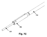
セグメント電極を有するリードは、様々な異なる方法で作ることができる。図6は、セグメント電極を有するリードの製造方法の1つの実施形態を説明するフローチャートである。ステップ602から始まり、例えば図7Aに示すように、複数の電極702、704をキャリア706に取付ける。特に、複数のセグメント電極702を一定の配列でキャリアに取付け、かかる一定の配列は、キャリアを円筒形に形成したときにセグメント電極がリード上で望ましい配列で位置決めされる配列(例えば、図2、図3A、図3B、及び図5に示す、例えば、1つ又は2つ以上のセットのセグメント電極のような配列)である。セグメント電極702は、任意適当な形状又はサイズで形成され、上述した材料で形成されるのがよい。少なくともいくつかの実施形態では、セグメント電極は、湾曲形状を有する。湾曲形状は、好ましくは、リードの曲率に一致する。例えば、セグメント電極の湾曲形状は、少なくとも10、15、20、30、40、50、又は60度の円弧を有する。セグメント電極の円弧は、345、330、320、300、270、180、又は175度よりも大きくないのがよい。いくつかの例では、セグメント電極の円弧は、10度〜345度の範囲、30度から300度の範囲、50度〜180度の範囲、又は、15度から175度の範囲にある。
Leads with segmented electrodes can be made in a variety of different ways. FIG. 6 is a flowchart illustrating one embodiment of a method for manufacturing a lead having segment electrodes. Beginning at
セグメント電極702は、選択的には、リード内にセグメント電極を保持するのを助ける1つ又は2つ以上の追加の特徴部を含む。いくつかの選択的な特徴部を示すセグメント電極702の1つの実施形態を図8に示す。セグメント電極は、リードを形成して患者に挿入したときに患者組織に露出される刺激表面804を含む。セグメント電極はまた、刺激表面804の反対側の内面806を含む。内面806は、リードの内部にある。セグメント電極702をリードの中に固定するのを助ける1つの選択的な特徴部は、内面806の波形の又はその他の粗い又は不均一なテクスチャ(表面状態)808である。内面806の不均一なテクスチャ808は、後で説明するように、セグメント電極702の周りに形成されるリード本体の材料に接触する表面積を増大させ、セグメント電極をリードの中に保持するのを助ける。波形のテクスチャ808は、図8に示すように三角形断面を有していてもよいし、その他の任意適当な形状を有していてもよく、かかる任意適当な形状は、限定するわけではないが、正方形、矩形、台形、半球形、六角形、又は任意その他の規則的な又は不規則的な断面を含む。適当な不均一なテクスチャの他の例は、限定するわけではないが、波形に類似し交差溝を有する碁盤目状配列、表面806から延びる複数のクリート状突起又はディンプルを有する配列、又は、表面のローレット加工、グリットブラスティング、又は他の粗面化方法等によって形成されたテクスチャを有する表面を含む。
The
セグメント電極702の別の選択的な特徴部は、1つ又は2つ以上の固定タブ810である。固定タブ810は、リードの内部及びセグメント電極の周りに形成されたリード本体の材料内に突出するように配置される。固定タブ810は、任意適当なサイズ又は形状を有し、選択的には、1つ又は2つ以上の孔812をタブ810内に含む。少なくともいくつかの実施形態では、リード本体からの材料は、成形プロセス中、孔812に流入して、追加の固定を行う。セグメント電極702が1つよりも多い固定タブ810を含むとき、固定タブ810は、セグメント電極702の周りに任意適当な配列で配置される。例えば、図8に示すように、2つの固定タブ810が、対向する側部から互いに向かって延びる。他の実施形態では、2つの固定タブは、セグメント電極702の特定の側部の一部のみから延びる。例えば、2つの固定タブは、2つのタブが斜めに対向するように、一方のタブが電極の側部の一方の端部の近くに延び、他方のタブが電極の反対側の側部の他方の端部の近くに延びるように、セグメント電極702から延びる。例えば、タブが直接対向する配列を含む他の配列を使用してもよいことを理解すべきである。
Another optional feature of the
図7Aに戻ると、選択的に1つ又は2つ以上のリング電極704が用いられる。これらのリング電極704は、図7Aに示すように、キャリアの端部に位置決めされてもよいし、セグメント電極のセットとセットの間に位置決めされてもよいし、それらの任意の組合せであってもよい。いくつかの実施形態では、リング電極を含まない(例えば、後で更に説明する図9A及び図9Bの実施形態を含む)ことを理解すべきである。
Returning to FIG. 7A, optionally one or
キャリア706は、リードの製造のために電極702、704が取付けられる一時的構造である。キャリアは、典型的には、比較的薄く、後で説明するように、円筒形に形成されるのに十分な可撓性を有する任意適当な材料で作られる。このような材料は、限定されるものではないが、金属(例えば、鉄、アルミニウム等)、合金(例えば、PM35N、鋼鉄、ステンレス鋼等)、及びプラスチック(可撓性回路に使用されるようなプラスチックフィルム、例えば、ポリイミド、ポリエーテルエーテルケトン(PEEK)、ポリエーテルイミド、ポリエチレンナフタレート、ポリエチレンテレフタレート、他のポリエステル、フルオロポリマー等)を含む。少なくともいくつかの実施形態では、後で説明するように、キャリアは、平坦(例えば、図9A参照)であってもよいし、円筒形の形成を見込んだ1つ又は2つ以上の湾曲部分(例えば、図7A及び図7Bを参照)に形成されてもよい。
The
電極702、704は、任意適当な方法によってキャリア706に取付けられ、かかる方法は、限定するわけではないが、溶接、半田付け、接着剤(例えば、エポキシ)を用いた装着等を含む。キャリア材料の選択は、電極をキャリアに取付ける方法を制限することがあり、取付け方法の選択は、使用できるキャリア材料を制限することがある点を理解すべきである。好ましくは、キャリア材料(及びキャリアに電極を取付けるのに用いられる半田又は接着剤等の任意の補助材料)は、生体適合性であり、その理由は、少量のかかる材料が最終リード上に留まる可能性があるからである。
The
キャリア706は、後で説明するように、円筒形へのキャリアの形成を容易にする1つ又は2つ以上の特徴部を含むのがよく、かかる特徴部は、スロット708及びタブ(タブ910について図9Aを参照)等である。かかる特徴部は、例えば、工具補助、位置合わせ補助、又はこれらの組合せとして作用する。
The
キャリア706への電極702、704の取付け後、例えば図7Bに示すように、導体712を電極702、704に取付ける(図6のステップ604)。導体712は、例えば、電極702、704と接触するように絶縁体の一部分が除去された絶縁ワイヤである。図7Bに示すように、異なる導体712を、各電極702、704に取付けてもよい。他の実施形態では、同じ導体を2つ又は3つ以上の電極に取付けてもよい。導体712は、任意適当な方法によって取付けられ、かかる方法は、限定するわけではないが、溶接、半田付け、圧接、導電性接着剤の使用等を含む。導体712は、電極702、704の任意適当な部分に取付けられる。例えば、導体712は、セグメント電極702の内面又はタブに取付けられ、或いは、リング電極704の内面に取付けられる。リング電極704は、導体712の取付けを容易にするノッチ714を含むのがよい。上述したように、導体712は、典型的には、リードの近位端部に配置された端子(図示せず)に取付けられる。電極の近位側にある導体の一部分は、ポリマー材料等で形成されたスリーブ716内に配置されてもよい。少なくともいくつかの実施形態では、スリーブ716は、リード本体の一部を形成する。少なくともいくつかの実施形態では、スリーブ716は、中心内腔(図示せず)及び導体712を担持する1つ又は2つ以上の外側内腔(図示せず)を定める。選択的には、中心内腔は、スタイレットを収容するのがよい。
After the
ステップ606において(図6参照)、例えば図7Cに示すように、キャリア706を円筒形に形成する。少なくともいくつかの実施形態では、円筒形の形成を容易にするために、キャリア706を、その上に配置された電極702、704と一緒に、マンドレル718の周りに巻く。図7Cに示すように、マンドレル718はまた、スリーブ716に(例えば、スリーブの中心内腔内に)部分的に挿入される。図7Cに示す実施形態は、円形断面を有する中空ロッドを示しているが、他の種類の中空ロッドを形成してもよいことを理解すべきであり、他の種類の中空ロッドは、限定するわけではないが、正方形、矩形、卵形、三角形、六角形、又は八角形の断面を有する中空ロッドを含む。
In step 606 (see FIG. 6), for example, as shown in FIG. 7C, the
キャリアは、任意適当な方法によって、円筒形態に保持される。いくつかの実施形態では、キャリアを円筒形に巻く成形具は、円筒形状の維持を容易にする。他の実施形態では、キャリアを円筒形態に保持するために、ストラップ又はファスナがキャリアに取付けられ、又は、キャリアの周りに巻かれる。変形例として又はそれに加えて、キャリアの2つ又は3つ以上の部分(例えば、タブ910(図9A)及びそれに対応するキャリアの反対側部分)を重ねてもよく、キャリアの重なり領域は、溶接、半田付け、接着剤の塗布等によって互いに取付けられる。更に他の実施形態では、キャリアは、いったん特定の形状に形成されたら、その形状を維持する。 The carrier is held in a cylindrical form by any suitable method. In some embodiments, a tool that winds the carrier in a cylindrical shape facilitates maintaining the cylindrical shape. In other embodiments, straps or fasteners are attached to or wrapped around the carrier to hold the carrier in a cylindrical configuration. As an alternative or in addition, two or more portions of the carrier (eg, tab 910 (FIG. 9A) and the corresponding opposite portion of the carrier) may overlap, and the carrier overlap region may be welded , Soldering, adhesive application, etc. In yet other embodiments, the carrier maintains its shape once formed into a particular shape.
いったんキャリアを円筒形に形成したら、リード本体720を、キャリア706及び電極702、704の周りに形成する(ステップ608)。リード本体720(図7E)の形成の一例を図7Dに示す。この例では、キャリア706及びそれと結合された電極702、704を型の中に配置する(説明を容易にするために、型の底部722のみを図7Dに示す)。マンドレル718は、リード内部に中心内腔を維持するために組立体内に留まるのがよい。(中心内腔は、リードの埋込み又は位置決めを助けるスタイレットを受入れるのに有用である。)キャリア706及びそれと結合された電極702、704を型に挿入し、型を閉鎖したら、プラスチック材料を型の中に導入し、リード本体720を形成する。任意適当な成形技術が用いられ、かかる成形技術は、限定するわけではないが、射出成形(例えば、回転式射出成形)及び圧縮成形を含む。リード本体720のプラスチック材料は、キャリア706の全て又は一部分を覆ってもよいし、変形例として、キャリアを覆わなくてもよい。リード本体720は、導体712を覆うスリーブ716の全てを覆ってもよいし、その一部分を覆ってもよい。(変形例として、導体は、スリーブ内に配置されなくてもよく、リード本体は、導体、キャリア706及び電極702、704の周りに成形される。)好ましくは、リード本体の材料をキャリアの下に導入して、電極702、704の周りに配置し、それにより、電極702、704の少なくとも内面をリード本体の材料に接触させ、タブが必要に応じてリード本体の材料の中に延びるようにする。
Once the carrier is formed into a cylindrical shape, a
リード本体に適当な材料は、シリコーン、ポリウレタン、ポリエチレン、ポリ尿素、ポリウレタン尿素、ポリエーテルエーテルケトン等の生体適合性ポリマー材料を含む。型の中に導入される材料は、ポリマー自体(例えば、流体又は半流体状態まで加熱されたポリマー)であってもよいし、成形プロセス中に重合されるプレポリマー材料(例えば、モノマー又はオリゴマー)であってもよい。図7Dに示すように、リード本体の形成後、組立体を型から取出す。単一の成形ステップを用いるプロセスを説明したけれども、同じ又は異なる材料を用いて、リード本体を成形する複数の成形ステップを利用してもよいことを理解すべきである。 Suitable materials for the lead body include biocompatible polymer materials such as silicone, polyurethane, polyethylene, polyurea, polyurethaneurea, polyetheretherketone and the like. The material introduced into the mold may be the polymer itself (eg, a polymer heated to a fluid or semi-fluid state) or a prepolymer material (eg, a monomer or oligomer) that is polymerized during the molding process. It may be. As shown in FIG. 7D, after forming the lead body, the assembly is removed from the mold. Although a process using a single molding step has been described, it should be understood that multiple molding steps for molding the lead body using the same or different materials may be utilized.
ステップ610(図6)に移ると、例えば図7Eに示すように、リード本体内に配置された電極702、704を残すように、キャリア706を除去する。キャリア706は、例えば、研削(例えば、芯なし研削)、エッチング、切断、キャリアを放出するための接着剤の分解、レーザー切除等の任意適当な方法によって除去される。キャリア706の除去に好適な方法は、キャリアの材料及びリードの他の構成要素(例えば、電極702、704及びリード本体720)に依存する。いくつかの実施形態では、キャリアの完全な又は略完全な除去を促進するために、キャリア706の除去はまた、電極702、704の露出面からの小部分の除去を含む。変形例として、キャリアの一部分を、1つ又は2つ以上の電極に残してもよい。
In step 610 (FIG. 6), for example, as shown in FIG. 7E, the
少なくともいくつかの実施形態では、マンドレル718を、キャリアの除去の前又は後に取除く。マンドレルを取除くことにより、中心内腔が残る。選択的には、ポリマー材料(又は他の材料)のプラグ724を、中心内腔の遠位端部に挿入して、中心内腔を閉鎖し、リードを埋込んだときの内腔内への体液の侵入を阻止する。選択的には、プラグをリード本体内に固着させるために、プラグを加熱によってリフローしてもよいし、接着剤を用いてもよい。
In at least some embodiments, the
上述したように、セグメント電極を含む電極の任意の配列を用いることができる。図9A及び図9Bは、電極の別の配列を示す。図9Aは、キャリア906を示し、セグメント電極902a、902bのみがキャリア上に配置されている。特定の例示的な実施形態では、セグメント電極902aは、円周方向に分配された3つの電極の2つのグループを形成し、セグメント電極902bは、円周方向に分配された2つの電極の2つのグループを形成する。最終リードの遠位端部を図9Bに示す。電極の各々が、異なる導体及びそれに結合された端子に取付けられてもよいけれども、少なくともいくつかの実施形態では、2つ又は3つ以上の電極が、同じ導体に取付けられ、電気的に結合されてもよい。例えば、遠位端部にある2つのセグメント電極902bのグループは、同じ導体に電気的に結合される(例えば、両方を同じ導体に直接取付けてもよいし、一方を導体に取付け、別のワイヤで2つの電極を短絡してもよい)。加えて、近位端部にある2つのセグメント電極902bのグループは、別の導体に電気的に結合されてもよい。変形例の電極配列は、特許文献10に説明され、特許文献10を本明細書に援用する。
As described above, any arrangement of electrodes including segment electrodes can be used. 9A and 9B show another arrangement of electrodes. FIG. 9A shows a
上記明細書、実施例、及びデータは、本発明の構成物の製造及び使用の説明を提供する。本発明の多くの実施形態は、本発明の精神及び範囲から逸脱することなく行うことができるので、本発明はまた、以下に添付された特許請求の範囲に属するものである。 The above specification, examples and data provide a description of the manufacture and use of the composition of the invention. Since many embodiments of the invention can be made without departing from the spirit and scope of the invention, the invention also resides in the claims hereinafter appended.
Claims (20)
複数のセグメント電極をキャリアに取付ける工程を含み、前記セグメント電極の各々は、10度〜345度の範囲の円弧にわたって延びる湾曲形態を有し、
さらに、複数の導体を前記複数のセグメント電極に取付ける工程と、
前記キャリアを円筒形に形成し、且つ、前記複数のセグメント電極を前記円筒形の中に配置する工程と、
リード本体を、前記キャリア上に配置された前記複数のセグメント電極の周りに成形する工程と、
前記キャリアの少なくとも一部分を除去して、前記セグメント電極を分離する工程と、を含む方法。 A method of manufacturing a stimulation lead, comprising:
Attaching a plurality of segment electrodes to a carrier, each of the segment electrodes having a curved configuration extending over an arc in the range of 10 degrees to 345 degrees;
Furthermore, attaching a plurality of conductors to the plurality of segment electrodes;
Forming the carrier in a cylindrical shape and disposing the plurality of segment electrodes in the cylindrical shape;
Forming a lead body around the plurality of segment electrodes disposed on the carrier;
Removing at least a portion of the carrier to separate the segment electrodes.
前記リード本体を成形する工程は、前記セグメント電極上のタブが前記リード本体の中に延びるように、前記リード本体を前記セグメント電極の周りに成形する工程を含む、請求項1に記載の方法。 Each of the segment electrodes includes a tab,
The method of claim 1, wherein forming the lead body includes forming the lead body around the segment electrode such that a tab on the segment electrode extends into the lead body.
複数のセグメント電極をキャリアに取付ける工程と、
複数の導体を前記複数のセグメント電極に取付ける工程と、
前記キャリアを円筒形に形成し、且つ、前記複数のセグメント電極を前記円筒形の中に配置する工程と、
リード本体を、前記キャリア上に配置された前記複数のセグメント電極の周りに成形する工程と、
前記キャリアの少なくとも一部分を研削して除去し、前記セグメント電極を分離する工程と、を含む方法。 A method of manufacturing a stimulation lead, comprising:
Attaching a plurality of segment electrodes to the carrier;
Attaching a plurality of conductors to the plurality of segment electrodes;
Forming the carrier in a cylindrical shape and disposing the plurality of segment electrodes in the cylindrical shape;
Forming a lead body around the plurality of segment electrodes disposed on the carrier;
Grinding and removing at least a portion of the carrier to separate the segment electrodes.
前記リード本体を成形する工程は、前記セグメント電極上のタブが前記リード本体の中に延びるように、前記リード本体を前記セグメント電極の周りに成形する工程を含む、請求項13に記載の方法。 Each of the segment electrodes includes a tab,
The method of claim 13, wherein forming the lead body includes forming the lead body around the segment electrode such that a tab on the segment electrode extends into the lead body.
複数のセグメント電極をキャリアに取付ける工程を含み、前記セグメント電極の各々は、波形の内面を有し、
さらに、複数の導体を前記複数のセグメント電極に取付ける工程と、
前記キャリアを円筒形に形成し、且つ、前記複数のセグメント電極を前記円筒形の中に配置する工程と、
リード本体を、前記キャリア上に配置された前記複数のセグメント電極の周りに成形する工程と、
前記キャリアの少なくとも一部分を除去して、前記セグメント電極を分離する工程と、を含む、方法。 A method of manufacturing a stimulation lead, comprising:
Attaching a plurality of segment electrodes to a carrier, each of the segment electrodes having a corrugated inner surface;
Furthermore, attaching a plurality of conductors to the plurality of segment electrodes;
Forming the carrier in a cylindrical shape and disposing the plurality of segment electrodes in the cylindrical shape;
Forming a lead body around the plurality of segment electrodes disposed on the carrier;
Removing at least a portion of the carrier to separate the segment electrodes.
前記リード本体を成形する工程は、前記セグメント電極上のタブが前記リード本体の中に延びるように、前記リード本体を前記セグメント電極の周りに成形する工程を含む、請求項19に記載の方法。 Each of the segment electrodes includes a tab,
20. The method of claim 19, wherein molding the lead body includes molding the lead body around the segment electrode such that a tab on the segment electrode extends into the lead body.
Applications Claiming Priority (3)
| Application Number | Priority Date | Filing Date | Title |
|---|---|---|---|
| US12/966,740 US8875391B2 (en) | 2009-07-07 | 2010-12-13 | Methods for making leads with radially-aligned segmented electrodes for electrical stimulation systems |
| US12/966,740 | 2010-12-13 | ||
| PCT/US2011/058160 WO2012082240A1 (en) | 2010-12-13 | 2011-10-27 | Methods for making leads with radially-aligned segmented electrodes for electrical stimulation systems |
Publications (2)
| Publication Number | Publication Date |
|---|---|
| JP2014500105A true JP2014500105A (en) | 2014-01-09 |
| JP5830107B2 JP5830107B2 (en) | 2015-12-09 |
Family
ID=44906490
Family Applications (1)
| Application Number | Title | Priority Date | Filing Date |
|---|---|---|---|
| JP2013544475A Expired - Fee Related JP5830107B2 (en) | 2010-12-13 | 2011-10-27 | Method for manufacturing a lead having radially aligned segment electrodes for an electrical stimulation system |
Country Status (6)
| Country | Link |
|---|---|
| US (2) | US8875391B2 (en) |
| EP (1) | EP2651498B1 (en) |
| JP (1) | JP5830107B2 (en) |
| AU (1) | AU2011341668B2 (en) |
| CA (1) | CA2819631A1 (en) |
| WO (1) | WO2012082240A1 (en) |
Families Citing this family (214)
| Publication number | Priority date | Publication date | Assignee | Title |
|---|---|---|---|---|
| US7860570B2 (en) | 2002-06-20 | 2010-12-28 | Boston Scientific Neuromodulation Corporation | Implantable microstimulators and methods for unidirectional propagation of action potentials |
| US7035690B2 (en) | 2002-11-15 | 2006-04-25 | Medtronic, Inc. | Human-implantable-neurostimulator user interface having multiple levels of abstraction |
| US8612024B2 (en) | 2006-02-24 | 2013-12-17 | Medtronic, Inc. | User interface with 3D environment for configuring stimulation therapy |
| US8380321B2 (en) | 2006-02-24 | 2013-02-19 | Medtronic, Inc. | Programming interface with a cross-sectional view of a stimulation lead with complex electrode array geometry |
| US8321025B2 (en) | 2006-07-31 | 2012-11-27 | Cranial Medical Systems, Inc. | Lead and methods for brain monitoring and modulation |
| US7583999B2 (en) | 2006-07-31 | 2009-09-01 | Cranial Medical Systems, Inc. | Multi-channel connector for brain stimulation system |
| KR101413677B1 (en) | 2007-03-19 | 2014-07-01 | 엠알아이 인터벤션즈, 인크. | Method and apparatus for manufacturing leads with conductors and related flexible lead configurations |
| EP2705874B1 (en) | 2007-03-19 | 2016-09-28 | Boston Scientific Neuromodulation Corporation | MRI and RF compatible leads |
| US7821524B2 (en) * | 2007-06-26 | 2010-10-26 | Microsoft Corporation | Adaptive contextual filtering |
| JP5653918B2 (en) | 2008-07-30 | 2015-01-14 | エコーレ ポリテクニーク フェデラーレ デ ローザンヌ (イーピーエフエル) | Apparatus and method for optimized stimulation of neural targets |
| US8359107B2 (en) | 2008-10-09 | 2013-01-22 | Boston Scientific Neuromodulation Corporation | Electrode design for leads of implantable electric stimulation systems and methods of making and using |
| US8788064B2 (en) | 2008-11-12 | 2014-07-22 | Ecole Polytechnique Federale De Lausanne | Microfabricated neurostimulation device |
| ES2718088T3 (en) | 2009-04-16 | 2019-06-27 | Boston Scient Neuromodulation Corp | Deep brain stimulation current conduction with divided electrodes |
| US8875391B2 (en) | 2009-07-07 | 2014-11-04 | Boston Scientific Neuromodulation Corporation | Methods for making leads with radially-aligned segmented electrodes for electrical stimulation systems |
| US8887387B2 (en) | 2009-07-07 | 2014-11-18 | Boston Scientific Neuromodulation Corporation | Methods of manufacture of leads with a radially segmented electrode array |
| US8295944B2 (en) | 2009-11-30 | 2012-10-23 | Boston Scientific Neuromodulation Corporation | Electrode array with electrodes having cutout portions and methods of making the same |
| US8874232B2 (en) | 2009-11-30 | 2014-10-28 | Boston Scientific Neuromodulation Corporation | Electrode array having concentric split ring electrodes and methods of making the same |
| US8788063B2 (en) | 2009-11-30 | 2014-07-22 | Boston Scientific Neuromodulation Corporation | Electrode array having a rail system and methods of manufacturing the same |
| US8391985B2 (en) | 2009-11-30 | 2013-03-05 | Boston Scientific Neuromodulation Corporation | Electrode array having concentric windowed cylinder electrodes and methods of making the same |
| US8571665B2 (en) * | 2010-03-23 | 2013-10-29 | Boston Scientific Neuromodulation Corporation | Helical radial spacing of contacts on a cylindrical lead |
| US9549708B2 (en) | 2010-04-01 | 2017-01-24 | Ecole Polytechnique Federale De Lausanne | Device for interacting with neurological tissue and methods of making and using the same |
| CA2798165A1 (en) | 2010-06-18 | 2011-12-22 | Boston Scientific Neuromodulation Corporation | Electrode array having embedded electrodes and methods of making the same |
| JP5940532B2 (en) | 2010-07-16 | 2016-06-29 | ボストン サイエンティフィック ニューロモデュレイション コーポレイション | System for radial steering of electrode arrays |
| US8583237B2 (en) | 2010-09-13 | 2013-11-12 | Cranial Medical Systems, Inc. | Devices and methods for tissue modulation and monitoring |
| US8694127B2 (en) | 2010-09-21 | 2014-04-08 | Boston Scientific Neuromodulation Corporation | Systems and methods for making and using radially-aligned segmented electrodes for leads of electrical stimulation systems |
| EP2654876B1 (en) | 2010-12-23 | 2014-12-10 | Boston Scientific Neuromodulation Corporation | Method and assembly for making a medical lead including removing raised connectors by grinding |
| US8700179B2 (en) | 2011-02-02 | 2014-04-15 | Boston Scientific Neuromodulation Corporation | Leads with spiral of helical segmented electrode arrays and methods of making and using the leads |
| US20120203316A1 (en) | 2011-02-08 | 2012-08-09 | Boston Scientific Neuromodulation Corporation | Leads with segmented electrodes for electrical stimulation of planar regions and methods of making and using |
| JP2014511227A (en) | 2011-02-08 | 2014-05-15 | ボストン サイエンティフィック ニューロモデュレイション コーポレイション | Method of manufacturing a lead having segmented electrodes for an electrical stimulation system |
| EP2673042B1 (en) | 2011-02-08 | 2019-01-09 | Boston Scientific Neuromodulation Corporation | Leads with segmented electrodes having a channel and methods of making the leads |
| US8886335B2 (en) | 2011-12-07 | 2014-11-11 | Boston Scientific Neuromodulation Corporation | Implantable leads with a low profile distal portion |
| AU2012352009B2 (en) | 2011-12-16 | 2015-05-07 | Boston Scientific Neuromodulation Corporation | System for programming a neurostimulation device with seamless integration programming modes |
| JP5908611B2 (en) | 2012-01-26 | 2016-04-26 | ボストン サイエンティフィック ニューロモデュレイション コーポレイション | System and method for identifying circumferential positioning of lead electrodes for electrical stimulation systems |
| US8744596B2 (en) | 2012-03-30 | 2014-06-03 | Boston Scientific Neuromodulation Corporation | Leads with X-ray fluorescent capsules for electrode identification and methods of manufacture and use |
| US9878148B2 (en) | 2012-04-17 | 2018-01-30 | Boston Scientific Neuromodulation Corporation | Lead with contact end conductor guide and methods of making and using |
| US9827413B2 (en) | 2012-04-17 | 2017-11-28 | Boston Scientific Neuromodulation Corporation | Lead construction for deep brain stimulation |
| WO2013162775A2 (en) | 2012-04-27 | 2013-10-31 | Medtronic, Inc. | Structures and techniques for medical lead fabrication |
| US9919148B2 (en) | 2012-05-25 | 2018-03-20 | Boston Scientific Neuromodulation Corporation | Distally curved electrical stimulation lead and methods of making and using |
| AU2013266508A1 (en) | 2012-05-25 | 2014-11-06 | Boston Scientific Neuromodulation Corporation | Methods for stimulating the dorsal root ganglion with a lead having segmented electrodes |
| US8768488B2 (en) | 2012-05-25 | 2014-07-01 | Boston Scientific Neuromodulation Corporation | Systems and methods for electrically stimulating patient tissue on or around one or more bony structures |
| US8849422B2 (en) | 2012-05-25 | 2014-09-30 | Boston Scientific Neuromodulation Corporation | Percutaneous implantation of an electrical stimulation lead for stimulating dorsal root ganglion |
| EP3111989B1 (en) * | 2012-06-01 | 2021-09-01 | Boston Scientific Neuromodulation Corporation | Leads with tip electrode for electrical stimulation systems |
| WO2014018092A1 (en) * | 2012-07-26 | 2014-01-30 | Medtronic, Inc. | Implantable medical leads |
| US8897891B2 (en) * | 2012-08-03 | 2014-11-25 | Boston Scientific Neuromodulation Corporation | Leads with electrode carrier for segmented electrodes and methods of making and using |
| CN113368397B (en) | 2013-03-15 | 2026-01-06 | 波士顿科学神经调制公司 | Systems and methods for delivering subthreshold therapy to patients |
| CA2910967A1 (en) | 2013-05-15 | 2014-11-20 | Boston Scientific Neuromodulation Corporation | Systems and methods for making and using tip electrodes for leads of electrical stimulation systems |
| US9498620B2 (en) * | 2013-05-31 | 2016-11-22 | Boston Scientific Neuromodulation Corporation | Leads containing segmented electrodes with non-perpendicular legs and methods of making and using |
| WO2014193759A1 (en) | 2013-05-31 | 2014-12-04 | Boston Scientific Neuromodulation Corporation | Segmented electrode leads formed from pre-electrodes with alignment features and mehods of making and using the leads |
| WO2014193761A1 (en) | 2013-05-31 | 2014-12-04 | Boston Scientific Neuromodulation Corporation | Methods for manufacturing segmented electrode leads using a removable ring and the leads formed thereby |
| CN105246542A (en) | 2013-05-31 | 2016-01-13 | 波士顿科学神经调制公司 | Segmented electrode leads formed from pre-electrodes with depressions or apertures and methods of making |
| JP2016519986A (en) * | 2013-05-31 | 2016-07-11 | ボストン サイエンティフィック ニューロモデュレイション コーポレイション | Lead having segment electrode and lead manufacturing method |
| WO2015006239A1 (en) | 2013-07-12 | 2015-01-15 | Boston Scientific Neuromodulation Corporation | Leads with segmented electrodes and methods of making and using the leads |
| US9655528B2 (en) | 2013-07-15 | 2017-05-23 | Boston Scientific Neuromodulation Corporation | Systems and methods for detecting cerebrospinal-fluid pulsation using an implantable electrical stimulation device |
| US9566747B2 (en) * | 2013-07-22 | 2017-02-14 | Boston Scientific Neuromodulation Corporation | Method of making an electrical stimulation lead |
| US9302113B2 (en) | 2013-07-29 | 2016-04-05 | Boston Scientific Neuromodulation Corporation | Systems and methods for identifying anode placement based on cerebrospinal fluid thickness |
| WO2015031375A1 (en) | 2013-08-30 | 2015-03-05 | Boston Scientific Neuromodulation Corporation | Methods of making segmented electrode leads using flanged carrier |
| US9775988B2 (en) | 2013-12-02 | 2017-10-03 | Boston Scientific Neuromodulation Corporation | Electrical stimulation leads with helically arranged electrodes and methods of making and using |
| US20150202432A1 (en) * | 2014-01-22 | 2015-07-23 | Pacesetter, Inc. | Electrode structure for deep brain stimulation |
| US9440066B2 (en) | 2014-01-27 | 2016-09-13 | Boston Scientific Neuromodulation Corporation | Systems and methods for making and using connector assemblies for implantable medical device systems |
| US11311718B2 (en) | 2014-05-16 | 2022-04-26 | Aleva Neurotherapeutics Sa | Device for interacting with neurological tissue and methods of making and using the same |
| CN106455985B (en) | 2014-05-16 | 2019-09-17 | 阿莱瓦神经治疗股份有限公司 | Devices that interact with nervous tissue and methods of making and using the same |
| WO2015192058A1 (en) | 2014-06-13 | 2015-12-17 | Boston Scientific Neuromodulation Corporation | Leads with electrode carriers for segmented electrodes and methods of making and using |
| US9925376B2 (en) | 2014-08-27 | 2018-03-27 | Aleva Neurotherapeutics | Treatment of autoimmune diseases with deep brain stimulation |
| US9474894B2 (en) | 2014-08-27 | 2016-10-25 | Aleva Neurotherapeutics | Deep brain stimulation lead |
| US9770598B2 (en) | 2014-08-29 | 2017-09-26 | Boston Scientific Neuromodulation Corporation | Systems and methods for making and using improved connector contacts for electrical stimulation systems |
| CA2962055C (en) | 2014-09-22 | 2018-10-23 | Boston Scientific Neuromodulation Corporation | Devices and methods to use power spectrum or signal association for pain management |
| US9901737B2 (en) | 2014-09-22 | 2018-02-27 | Boston Scientific Neuromodulation Corporation | Systems and methods for providing therapy to a patient using intermittent electrical stimulation |
| US9925377B2 (en) | 2014-09-22 | 2018-03-27 | Boston Scientific Neuromodulation Corporation | Systems and methods for providing therapy using electrical stimulation to disrupt neuronal activity |
| US9814881B2 (en) | 2014-09-22 | 2017-11-14 | Boston Scientific Neuromodulation Corporation | Systems and methods for providing therapy using electrical stimulation to disrupt neuronal activity |
| EP3197548A1 (en) | 2014-09-22 | 2017-08-02 | Boston Scientific Neuromodulation Corporation | Devices using a pathological frequency in electrical stimulation for pain management |
| EP3204112A1 (en) | 2014-10-07 | 2017-08-16 | Boston Scientific Neuromodulation Corporation | Systems, devices, and methods for electrical stimulation using feedback to adjust stimulation parameters |
| US20160121103A1 (en) | 2014-11-03 | 2016-05-05 | Boston Scientific Neuromodulation Corporation | Electrical stimulation system with anchoring stylet and methods of making and using |
| US9604068B2 (en) | 2014-11-10 | 2017-03-28 | Boston Scientific Neuromodulation Corporation | Systems and methods for making and using improved connector contacts for electrical stimulation systems |
| US9561362B2 (en) | 2014-11-10 | 2017-02-07 | Boston Scientific Neuromodulation Corporation | Systems and methods for making and using improved contact arrays for electrical stimulation systems |
| EP3229891B1 (en) | 2015-02-06 | 2019-08-14 | Boston Scientific Neuromodulation Corporation | Systems with improved contact arrays for electrical stimulation systems |
| US9833611B2 (en) | 2015-04-10 | 2017-12-05 | Boston Scientific Neuromodulation Corporation | Systems and methods for making and using improved contact arrays for electrical stimulation systems |
| WO2016191436A1 (en) | 2015-05-26 | 2016-12-01 | Boston Scientific Neuromodulation Corporation | Systems and methods for analyzing electrical stimulation and selecting or manipulating volumes of activation |
| US20160375248A1 (en) | 2015-06-29 | 2016-12-29 | Boston Scientific Neuromodulation Corporation | Systems and methods for selecting stimulation parameters based on stimulation target region, effects, or side effects |
| WO2017003947A1 (en) | 2015-06-29 | 2017-01-05 | Boston Scientific Neuromodulation Corporation | Systems and methods for selecting stimulation parameters by targeting and steering |
| WO2017011477A1 (en) | 2015-07-16 | 2017-01-19 | Boston Scientific Neuromodulation Corporation | Systems and methods for making and using connector contact arrays for electrical stimulation systems |
| US10232169B2 (en) | 2015-07-23 | 2019-03-19 | Boston Scientific Neuromodulation Corporation | Burr hole plugs for electrical stimulation systems and methods of making and using |
| US10067659B2 (en) | 2015-08-24 | 2018-09-04 | Boston Scientific Neuromodulation Corporation | Systems and methods for determining orientation of an implanted lead |
| WO2017040573A1 (en) | 2015-09-01 | 2017-03-09 | Boston Scientific Neuromodulation Corporation | Detection of lead orientation |
| US9956394B2 (en) | 2015-09-10 | 2018-05-01 | Boston Scientific Neuromodulation Corporation | Connectors for electrical stimulation systems and methods of making and using |
| US10456584B2 (en) | 2015-09-15 | 2019-10-29 | Boston Scientific Neuromodulation Corporation | User interface for neuromodulation lead |
| US10413737B2 (en) | 2015-09-25 | 2019-09-17 | Boston Scientific Neuromodulation Corporation | Systems and methods for providing therapy using electrical stimulation to disrupt neuronal activity |
| EP3359252B1 (en) | 2015-10-09 | 2020-09-09 | Boston Scientific Neuromodulation Corporation | System and methods for clinical effects mapping for directional stimulations leads |
| US9986989B2 (en) | 2016-01-08 | 2018-06-05 | Boston Scientific Neuromodulation Corporation | Surgical retractor for implanting leads and methods of making and using |
| US10342983B2 (en) | 2016-01-14 | 2019-07-09 | Boston Scientific Neuromodulation Corporation | Systems and methods for making and using connector contact arrays for electrical stimulation systems |
| US10814127B2 (en) | 2016-02-05 | 2020-10-27 | Boston Scientific Neuromodulation Corporation | Slotted sleeve neurostimulation device |
| WO2017136346A1 (en) | 2016-02-05 | 2017-08-10 | Boston Scientfic Neuromodulation Corporation | Implantable optical stimulation lead |
| EP3389763B1 (en) | 2016-02-19 | 2023-06-28 | Boston Scientific Neuromodulation Corporation | Electrical stimulation cuff devices and systems |
| US10071242B2 (en) | 2016-02-29 | 2018-09-11 | Boston Scientific Neuromodulation Corporation | Lead anchor for an electrical stimulation system |
| US10124161B2 (en) | 2016-03-31 | 2018-11-13 | Boston Scientific Neuromodulation Corporation | Neurostimulation lead with conductive elements and methods for making the same |
| US10716942B2 (en) | 2016-04-25 | 2020-07-21 | Boston Scientific Neuromodulation Corporation | System and methods for directional steering of electrical stimulation |
| US10369354B2 (en) | 2016-05-17 | 2019-08-06 | Boston Scientific Neuromodulation Corporation | Systems and method for anchoring a lead for neurostimulation of a target anatomy |
| US10493269B2 (en) | 2016-06-02 | 2019-12-03 | Boston Scientific Neuromodulation Corporation | Leads for electrostimulation of peripheral nerves and other targets |
| US10201713B2 (en) | 2016-06-20 | 2019-02-12 | Boston Scientific Neuromodulation Corporation | Threaded connector assembly and methods of making and using the same |
| JP6905541B2 (en) | 2016-06-24 | 2021-07-21 | ボストン サイエンティフィック ニューロモデュレイション コーポレイション | Systems and methods for visual analysis of clinical effects |
| US10307602B2 (en) | 2016-07-08 | 2019-06-04 | Boston Scientific Neuromodulation Corporation | Threaded connector assembly and methods of making and using the same |
| WO2018022455A1 (en) | 2016-07-29 | 2018-02-01 | Boston Scientific Neuromodulation Corporation | Connector assembly with contact rings comprising biased ball-spring contacts |
| WO2018022460A1 (en) | 2016-07-29 | 2018-02-01 | Boston Scientific Neuromodulation Corporation | Systems and methods for making and using an electrical stimulation system for peripheral nerve stimulation |
| WO2018039117A1 (en) | 2016-08-22 | 2018-03-01 | Boston Scientific Neuromodulation Corporation | Neuromodulation system for providing paresthesia and analgesia and a system with leads and with electrodes |
| US10350404B2 (en) | 2016-09-02 | 2019-07-16 | Boston Scientific Neuromodulation Corporation | Systems and methods for visualizing and directing stimulation of neural elements |
| US10780282B2 (en) | 2016-09-20 | 2020-09-22 | Boston Scientific Neuromodulation Corporation | Systems and methods for steering electrical stimulation of patient tissue and determining stimulation parameters |
| US10543374B2 (en) | 2016-09-30 | 2020-01-28 | Boston Scientific Neuromodulation Corporation | Connector assemblies with bending limiters for electrical stimulation systems and methods of making and using same |
| EP3493875B1 (en) | 2016-10-14 | 2020-05-27 | Boston Scientific Neuromodulation Corporation | Systems and methods for determining orientation of an implanted lead |
| WO2018071865A1 (en) | 2016-10-14 | 2018-04-19 | Boston Scientific Neuromodulation Corporation | Systems and methods for closed-loop determination of stimulation parameter settings for an electrical simulation system |
| US10525257B2 (en) | 2016-10-14 | 2020-01-07 | Boston Scientific Neuromodulation Corporation | Orientation marker for implantable leads and leads, systems, and methods utilizing the orientation marker |
| US10625072B2 (en) | 2016-10-21 | 2020-04-21 | Boston Scientific Neuromodulation Corporation | Electrical stimulation methods with optical observation and devices therefor |
| US10716935B2 (en) | 2016-11-04 | 2020-07-21 | Boston Scientific Neuromodulation Corporation | Electrical stimulation leads, systems and methods for stimulation of dorsal root ganglia |
| US10603485B2 (en) | 2016-11-28 | 2020-03-31 | Boston Scientific Neuromodulation Corporation | Features in increased surface area on neuromodulation leads |
| WO2018102773A1 (en) | 2016-12-02 | 2018-06-07 | Boston Scientific Neuromodulation Corporation | Methods and systems for selecting stimulation parameters for electrical stimulation devices |
| US10576269B2 (en) | 2017-01-03 | 2020-03-03 | Boston Scientific Neuromodulation Corporation | Force-decoupled and strain relieving lead and methods of making and using |
| EP3515548B1 (en) | 2017-01-03 | 2021-03-17 | Boston Scientific Neuromodulation Corporation | Systems and methods for selecting mri-compatible stimulation parameters |
| ES2821752T3 (en) | 2017-01-10 | 2021-04-27 | Boston Scient Neuromodulation Corp | Systems and procedures for creating stimulation programs based on user-defined areas or volumes |
| WO2018132367A1 (en) | 2017-01-10 | 2018-07-19 | Boston Scientific Neuromodulation Corporation | Patterned stimulation for deep brain stimulation |
| US10905871B2 (en) | 2017-01-27 | 2021-02-02 | Boston Scientific Neuromodulation Corporation | Lead assemblies with arrangements to confirm alignment between terminals and contacts |
| US10814136B2 (en) | 2017-02-28 | 2020-10-27 | Boston Scientific Neuromodulation Corporation | Toolless connector for latching stimulation leads and methods of making and using |
| US10709886B2 (en) | 2017-02-28 | 2020-07-14 | Boston Scientific Neuromodulation Corporation | Electrical stimulation leads and systems with elongate anchoring elements and methods of making and using |
| US10625082B2 (en) | 2017-03-15 | 2020-04-21 | Boston Scientific Neuromodulation Corporation | Visualization of deep brain stimulation efficacy |
| US10835739B2 (en) | 2017-03-24 | 2020-11-17 | Boston Scientific Neuromodulation Corporation | Electrical stimulation leads and systems with elongate anchoring elements and methods of making and using |
| US11357986B2 (en) | 2017-04-03 | 2022-06-14 | Boston Scientific Neuromodulation Corporation | Systems and methods for estimating a volume of activation using a compressed database of threshold values |
| US10603499B2 (en) | 2017-04-07 | 2020-03-31 | Boston Scientific Neuromodulation Corporation | Tapered implantable lead and connector interface and methods of making and using |
| US10631937B2 (en) | 2017-04-14 | 2020-04-28 | Boston Scientific Neuromodulation Corporation | Systems and methods for determining orientation of an implanted electrical stimulation lead |
| US10857351B2 (en) | 2017-04-28 | 2020-12-08 | Boston Scientific Neuromodulation Corporation | Lead anchors for electrical stimulation leads and systems and methods of making and using |
| US20180333173A1 (en) | 2017-05-22 | 2018-11-22 | Boston Scientific Neuromodulation Corporation | Systems and methods for making and using a lead introducer for an electrical stimulation system |
| US10814140B2 (en) | 2017-06-26 | 2020-10-27 | Boston Scientific Neuromodulation Corporation | Systems and methods for visualizing and controlling optogenetic stimulation using optical stimulation systems |
| US20180369606A1 (en) | 2017-06-26 | 2018-12-27 | Boston Scientific Neuromodulation Corporationd | Systems and methods for making and using implantable optical stimulation leads and assemblies |
| CN110944710B (en) | 2017-07-14 | 2023-12-29 | 波士顿科学神经调制公司 | System and method for estimating clinical effects of electrical stimulation |
| US20190015660A1 (en) | 2017-07-14 | 2019-01-17 | Boston Scientific Neuromodulation Corporation | Systems and methods for planning and programming electrical stimulation |
| WO2019023067A1 (en) | 2017-07-25 | 2019-01-31 | Boston Scientific Neuromodulation Corporation | Systems and methods for making and using an enhanced connector of an electrical stimulation system |
| WO2019036180A1 (en) | 2017-08-15 | 2019-02-21 | Boston Scientific Neuromodulation Corporation | Systems and methods for controlling electrical stimulation using multiple stimulation fields |
| US11219759B2 (en) | 2017-08-29 | 2022-01-11 | Boston Scientific Neuromodulation Corporation | Systems and methods for introducing an electrical stimulation lead into a patient |
| AU2018331521B2 (en) | 2017-09-15 | 2021-07-22 | Boston Scientific Neuromodulation Corporation | Biased lead connector for operating room cable assembly and methods of making and using |
| EP3681587B1 (en) | 2017-09-15 | 2023-08-23 | Boston Scientific Neuromodulation Corporation | Actuatable lead connector for an operating room cable assembly |
| US11139603B2 (en) | 2017-10-03 | 2021-10-05 | Boston Scientific Neuromodulation Corporation | Connectors with spring contacts for electrical stimulation systems and methods of making and using same |
| CN111344042B (en) | 2017-11-13 | 2023-09-26 | 波士顿科学神经调制公司 | Systems and methods for making and using low profile control modules for electrical stimulation systems |
| AU2018367627B2 (en) | 2017-11-17 | 2021-09-23 | Boston Scientific Neuromodulation Corporation | Systems and methods for generating intermittent stimulation using electrical stimulation systems |
| US10967192B2 (en) | 2017-12-29 | 2021-04-06 | Boston Scientific Neuromodulation Corporation | Systems and methods for charging a medical device implanted into a patient |
| EP3737464A1 (en) | 2018-01-11 | 2020-11-18 | Boston Scientific Neuromodulation Corporation | Methods and systems for stimulation for glial modulation |
| WO2019143574A1 (en) | 2018-01-16 | 2019-07-25 | Boston Scientific Neuromodulation Corporation | An electrical stimulation system with a case-neutral battery and a control module for such a system |
| US11103712B2 (en) | 2018-01-16 | 2021-08-31 | Boston Scientific Neuromodulation Corporation | Connector assemblies with novel spacers for electrical stimulation systems and methods of making and using same |
| US11357544B2 (en) | 2018-01-25 | 2022-06-14 | Boston Scientific Neuromodulation Corporation | Systems and methods for introducing a stimulation lead into a patient |
| US10702692B2 (en) | 2018-03-02 | 2020-07-07 | Aleva Neurotherapeutics | Neurostimulation device |
| WO2019173281A1 (en) | 2018-03-09 | 2019-09-12 | Boston Scientific Neuromodulation Corporation | Burr hole plugs for electrical stimulation systems |
| EP3765142B1 (en) | 2018-03-16 | 2022-05-04 | Boston Scientific Neuromodulation Corporation | Kit for securing burr hole plugs for stimulation systems |
| US20210008389A1 (en) | 2018-03-23 | 2021-01-14 | Boston Scientific Neuromodulation Corporation | Optical stimulation system with automated monitoring and methods of making and using |
| WO2019183078A1 (en) | 2018-03-23 | 2019-09-26 | Boston Scientific Neuromodulation Corporation | Optical stimulation systems using therapy cycling and methods of using |
| US11565131B2 (en) | 2018-03-23 | 2023-01-31 | Boston Scientific Neuromodulation Corporation | Optical stimulation systems with calibration and methods of making and using |
| WO2019183082A1 (en) | 2018-03-23 | 2019-09-26 | Boston Scientific Neuromodulation Corporation | Implantable prostheses for reducing visibility of bulging from implanted medical devices |
| WO2019183068A1 (en) | 2018-03-23 | 2019-09-26 | Boston Scientific Neuromodulation Corporation | An optical stimulation system with on-demand monitoring and methods of making and using |
| US11285329B2 (en) | 2018-04-27 | 2022-03-29 | Boston Scientific Neuromodulation Corporation | Systems and methods for visualizing and programming electrical stimulation |
| WO2019210202A1 (en) | 2018-04-27 | 2019-10-31 | Boston Scientific Neuromodulation Corporation | Multi-mode electrical stimulation systems and methods of making and using |
| US11172959B2 (en) | 2018-05-02 | 2021-11-16 | Boston Scientific Neuromodulation Corporation | Long, flexible sheath and lead blank and systems and methods of making and using |
| WO2019217415A1 (en) | 2018-05-11 | 2019-11-14 | Boston Scientific Neuromodulation Corporation | Connector assembly for an electrical stimulation system |
| AU2019302442B2 (en) | 2018-07-09 | 2022-06-30 | Boston Scientific Neuromodulation Corporation | Directional electrical stimulation leads and systems for spinal cord stimulation |
| EP3603721B1 (en) * | 2018-07-31 | 2022-05-11 | Heraeus Deutschland GmbH & Co. KG | Catheter with segmented electrodes and methods of making same |
| US11224743B2 (en) | 2018-09-21 | 2022-01-18 | Boston Scientific Neuromodulation Corporation | Systems and methods for making and using modular leads for electrical stimulation systems |
| WO2020102039A1 (en) | 2018-11-16 | 2020-05-22 | Boston Scientific Neuromodulation Corporation | An optical stimulation system with on-demand monitoring and methods of making |
| US11167128B2 (en) | 2018-11-16 | 2021-11-09 | Boston Scientific Neuromodulation Corporation | Directional electrical stimulation leads, systems and methods for spinal cord stimulation |
| EP3673951B1 (en) | 2018-12-28 | 2022-05-04 | Heraeus Medical Components, LLC | Overmolded segmented electrode |
| US11529510B2 (en) | 2019-02-19 | 2022-12-20 | Boston Scientific Neuromodulation Corporation | Lead introducers and systems and methods including the lead introducers |
| WO2020205843A1 (en) | 2019-04-01 | 2020-10-08 | Boston Scientific Neuromodulation Corporation | Systems and methods for making and using a low-profile control module for an electrical stimulation system |
| US11357992B2 (en) | 2019-05-03 | 2022-06-14 | Boston Scientific Neuromodulation Corporation | Connector assembly for an electrical stimulation system and methods of making and using |
| WO2020243096A1 (en) | 2019-05-30 | 2020-12-03 | Boston Scientific Neuromodulation Corporation | Methods and systems for discrete measurement of electrical characteristics |
| ES3030122T3 (en) | 2019-06-20 | 2025-06-26 | Boston Scient Neuromodulation Corp | Systems for interleaving waveforms for electrical stimulation and measurement |
| WO2021021659A1 (en) | 2019-07-26 | 2021-02-04 | Boston Scientific Neuromodulation Corporation | Methods and systems for storage, retrieval, and visualization of signals and signal features |
| US12053632B2 (en) | 2019-07-26 | 2024-08-06 | Boston Scientific Neuromodulation Corporation | Methods and systems for making electrical stimulation adjustments based on patient-specific factors |
| WO2021086784A1 (en) | 2019-10-28 | 2021-05-06 | Boston Scientific Neuromodulation Corporation | Systems and methods for measuring temperature on or near an implantable medical device |
| CN115135371A (en) | 2020-02-19 | 2022-09-30 | 波士顿科学神经调制公司 | Method and system for treating insomnia using deep brain stimulation |
| US11806547B2 (en) | 2020-09-04 | 2023-11-07 | Boston Scientific Neuromodulation Corporation | Stimulation systems with a lens arrangement for light coupling and methods of making and using |
| US12402004B2 (en) | 2020-11-04 | 2025-08-26 | Boston Scient ation Corporation | Methods and systems for managing access to implantable medical devices |
| US12002462B2 (en) | 2020-11-11 | 2024-06-04 | Boston Scientific Neuromodulation Corporation | Voice command handler for programming stimulation systems and methods of using |
| AU2022210245B2 (en) | 2021-01-19 | 2025-04-03 | Boston Scientific Neuromodulation Corporation | Electrical stimulation cuff devices and systems with directional electrode configurations |
| JP7688170B2 (en) | 2021-02-25 | 2025-06-03 | ボストン サイエンティフィック ニューロモデュレイション コーポレイション | Method and system for deep brain stimulation of the nucleus basalis of meynert |
| WO2022216844A1 (en) | 2021-04-08 | 2022-10-13 | Boston Scientific Neuromodulation Corporation | Photobiomodulation system and delivery device |
| EP4291294A1 (en) | 2021-04-27 | 2023-12-20 | Boston Scientific Neuromodulation Corporation | Systems and methods for automated programming of electrical stimulation |
| US12194291B2 (en) | 2021-05-21 | 2025-01-14 | Boston Scientific Neuromodulation Corporation | Electrical stimulation cuff devices and systems with helical arrangement of electrodes |
| WO2022261004A1 (en) | 2021-06-07 | 2022-12-15 | Boston Scientific Neuromodulation Corporation | Methods and systems for charge balancing of electrical stimulation |
| WO2022261001A1 (en) | 2021-06-07 | 2022-12-15 | Boston Scientific Neuromodulation Corporation | Stimulation systems with user-specified routines and methods of making and using |
| EP4313269A1 (en) | 2021-06-15 | 2024-02-07 | Boston Scientific Neuromodulation Corporation | Methods and systems for estimating neural activation by stimulation using a stimulation system |
| US12343547B2 (en) | 2021-08-19 | 2025-07-01 | Boston Scientific Neuromodulation Corporation | Connectors for an electrical stimulation system and methods of making and using |
| CN118251257A (en) | 2021-12-09 | 2024-06-25 | 波士顿科学神经调制公司 | Methods and systems for monitoring or assessing movement disorders or other physiological parameters using a stimulation system |
| EP4415809B1 (en) | 2021-12-10 | 2026-01-28 | Boston Scientific Neuromodulation Corporation | Systems and methods for generating and using response maps for electrical stimulation |
| US20230181089A1 (en) | 2021-12-10 | 2023-06-15 | Boston Scientific Neuromodulation Corporation | Methods and systems for determining and using an intensity index for electrical stimulation |
| EP4475936A1 (en) | 2022-02-10 | 2024-12-18 | Boston Scientific Neuromodulation Corporation | Automatic therapy adjustment based on sensors |
| WO2023163882A1 (en) | 2022-02-24 | 2023-08-31 | Boston Scientific Neuromodulation Corporation | Systems and methods for using cost parameters for programming electrical stimulation |
| US12533520B2 (en) | 2022-03-02 | 2026-01-27 | Boston Scientific Neuromodulation Corporation | Systems and methods for monitoring stimulation drift in an electrical stimulation system |
| WO2024044048A1 (en) | 2022-08-22 | 2024-02-29 | Boston Scientific Neuromodulation Corporation | Photobiomodulation systems including an electrode disposed on or over a light emitter and methods of making and using |
| US20240058619A1 (en) | 2022-08-22 | 2024-02-22 | Boston Scientific Neuromodulation Corporation | Implantable photobiomodulation systems employing thermal monitoring or control and methods of making and using |
| EP4368242A1 (en) | 2022-11-14 | 2024-05-15 | Boston Scientific Neuromodulation Corporation | Systems and methods for generating and using stimulation programs with temporal variation |
| EP4590390A1 (en) | 2022-12-14 | 2025-07-30 | Boston Scientific Neuromodulation Corporation | Systems and methods for monitoring and revising electrical stimulation |
| WO2024141768A2 (en) | 2022-12-29 | 2024-07-04 | Benabid Alim Louis | Optical stimulation systems and methods for implanting and using |
| EP4398258A3 (en) | 2023-01-04 | 2024-08-28 | Boston Scientific Neuromodulation Corporation | Systems and methods incorporating a light therapy user interface for optical modulation |
| EP4646260A1 (en) | 2023-03-22 | 2025-11-12 | Boston Scientific Neuromodulation Corporation | Systems for moving stimulation using anatomical directional controls |
| WO2024226642A2 (en) | 2023-04-28 | 2024-10-31 | Boston Scientific Neuromodulation Corporation | Systems and methods for modifying stimulation in response to a change in a symptom, therapeutic effect, or side effect |
| WO2025010358A1 (en) | 2023-07-06 | 2025-01-09 | Boston Scientific Neuromodulation Corporation | Systems and methods for selecting electrodes and providing stimulation |
| US20250050104A1 (en) | 2023-08-10 | 2025-02-13 | Boston Scientific Neuromodulation Corporation | Enhancing neuromodulation for sleep |
| US20250050107A1 (en) | 2023-08-11 | 2025-02-13 | Boston Scientific Neuromodulation Corporation | Methods and systems for control and modification of stimulation |
| US20250058120A1 (en) | 2023-08-16 | 2025-02-20 | Boston Scientific Neuromodulation Corporation | Integration of fiber tracts into deep brain stimulation targeting |
| AU2024323416A1 (en) | 2023-08-16 | 2026-01-29 | Boston Scientific Neuromodulation Corporation | Integration of related probability shells into deep brain stimulation targeting |
| US20250058116A1 (en) | 2023-08-16 | 2025-02-20 | Boston Scientific Neuromodulation Corporation | Photobiomodulation of basal forebrain to improve cognition |
| WO2025054405A1 (en) | 2023-09-07 | 2025-03-13 | Boston Scientific Neuromodulation Corporation | System and method for modulating neural synchrony |
| WO2025059218A1 (en) * | 2023-09-11 | 2025-03-20 | Albert Einstein College Of Medicine | Intermittent responsive implanted stimulation and adaptive behavioral training system |
| WO2025059213A1 (en) | 2023-09-13 | 2025-03-20 | Boston Scientific Neuromodulation Corporation | Coiled ring contacts for electrical stimulation systems and methods of making and using same |
| US20250099749A1 (en) | 2023-09-21 | 2025-03-27 | Boston Scientific Neuromodulation Corporation | Electrical stimulation cuff devices and systems and electrode arrangements therefor |
| WO2025075826A1 (en) | 2023-10-02 | 2025-04-10 | Boston Scientific Neuromodulation Corporation | Lead introducers and systems including the lead introducers |
| WO2025096870A1 (en) | 2023-11-02 | 2025-05-08 | Boston Scientific Neuromodulation Corporation | Optimization of dbs program using a prespecified selection of contacts |
| EP4552688A3 (en) | 2023-11-09 | 2025-05-28 | Boston Scientific Neuromodulation Corporation | Photobiomodulation systems utilizing monitoring or electrical stimulation and methods of making and using |
| US20250242159A1 (en) | 2024-01-30 | 2025-07-31 | Boston Scientific Neuromodulation Corporation | System and method for combined photobiomodulation and electrical stimulation for epilepsy |
| US20250367448A1 (en) | 2024-06-04 | 2025-12-04 | Boston Scientific Neuromodulation Corporation | Systems and methods for evoked signal sensing using adjustable dc offset compensation |
| WO2026015468A1 (en) | 2024-07-09 | 2026-01-15 | Boston Scientific Neuromodulation Corporation | Electrical stimulation cuff leads and systems and methods of making and using |
| US20260021290A1 (en) | 2024-07-17 | 2026-01-22 | Boston Scientific Neuromodulation Corporation | Systems and methods for programming and visualization of peripheral nerve stimulation |
Family Cites Families (156)
| Publication number | Priority date | Publication date | Assignee | Title |
|---|---|---|---|---|
| US177823A (en) | 1876-05-23 | Improvement in platform-scales | ||
| US2295308A (en) | 1938-02-26 | 1942-09-08 | Gen Electric | High speed reclosing mechanism |
| SE390802B (en) | 1973-11-27 | 1977-01-24 | Atomenergi Ab | PROCEDURE FOR ASSEMBLING DETAILS OF WORKED POLYMERS |
| US4630611A (en) | 1981-02-02 | 1986-12-23 | Medtronic, Inc. | Orthogonally-sensing lead |
| US4602624A (en) | 1984-10-11 | 1986-07-29 | Case Western Reserve University | Implantable cuff, method of manufacture, and method of installation |
| CA1240784A (en) | 1985-08-30 | 1988-08-16 | Patrick D. Van Der Puije | Cochlea implant |
| US4744370A (en) | 1987-04-27 | 1988-05-17 | Cordis Leads, Inc. | Lead assembly with selectable electrode connection |
| US5000194A (en) | 1988-08-25 | 1991-03-19 | Cochlear Corporation | Array of bipolar electrodes |
| US5016646A (en) | 1988-11-29 | 1991-05-21 | Telectronics, N.V. | Thin electrode lead and connections |
| US5199433A (en) | 1989-02-06 | 1993-04-06 | Arzco Medical Systems, Inc. | Esophageal recording/pacing catheter with thermistor and cardiac imaging transceiver |
| US5135001A (en) | 1990-12-05 | 1992-08-04 | C. R. Bard, Inc. | Ultrasound sheath for medical diagnostic instruments |
| US6509032B1 (en) * | 1991-08-28 | 2003-01-21 | Mcmaster University | Cationic amphiphiles |
| EP0580928A1 (en) | 1992-07-31 | 1994-02-02 | ARIES S.r.l. | A spinal electrode catheter |
| ZA948393B (en) | 1993-11-01 | 1995-06-26 | Polartechnics Ltd | Method and apparatus for tissue type recognition |
| US5458629A (en) | 1994-02-18 | 1995-10-17 | Medtronic, Inc. | Implantable lead ring electrode and method of making |
| US5522874A (en) | 1994-07-28 | 1996-06-04 | Gates; James T. | Medical lead having segmented electrode |
| US5599532A (en) * | 1994-08-12 | 1997-02-04 | Chesebrough-Pond's Usa Co., Division Of Conopco, Inc. | Sprayable hair treatment composition |
| WO1997032628A1 (en) | 1996-03-07 | 1997-09-12 | Axon Engineering, Inc. | Polymer-metal foil structure for neural stimulating electrodes |
| US5713922A (en) | 1996-04-25 | 1998-02-03 | Medtronic, Inc. | Techniques for adjusting the locus of excitation of neural tissue in the spinal cord or brain |
| US5711316A (en) | 1996-04-30 | 1998-01-27 | Medtronic, Inc. | Method of treating movement disorders by brain infusion |
| US5843148A (en) | 1996-09-27 | 1998-12-01 | Medtronic, Inc. | High resolution brain stimulation lead and method of use |
| US5938688A (en) | 1997-10-22 | 1999-08-17 | Cornell Research Foundation, Inc. | Deep brain stimulation method |
| US6161047A (en) | 1998-04-30 | 2000-12-12 | Medtronic Inc. | Apparatus and method for expanding a stimulation lead body in situ |
| US6134478A (en) | 1998-06-05 | 2000-10-17 | Intermedics Inc. | Method for making cardiac leads with zone insulated electrodes |
| US6181969B1 (en) | 1998-06-26 | 2001-01-30 | Advanced Bionics Corporation | Programmable current output stimulus stage for implantable device |
| US6322559B1 (en) | 1998-07-06 | 2001-11-27 | Vnus Medical Technologies, Inc. | Electrode catheter having coil structure |
| US6018684A (en) | 1998-07-30 | 2000-01-25 | Cardiac Pacemakers, Inc. | Slotted pacing/shocking electrode |
| DE19838636A1 (en) * | 1998-08-26 | 2000-03-02 | Basf Ag | Carotenoid formulations containing a mixture of beta-carotene, lycopene and lutein |
| ATE306213T1 (en) | 1998-12-23 | 2005-10-15 | Nuvasive Inc | DEVICES FOR CANNULATION AND NERVE MONITORING |
| US6564078B1 (en) | 1998-12-23 | 2003-05-13 | Nuvasive, Inc. | Nerve surveillance cannula systems |
| US6393325B1 (en) | 1999-01-07 | 2002-05-21 | Advanced Bionics Corporation | Directional programming for implantable electrode arrays |
| US6216045B1 (en) | 1999-04-26 | 2001-04-10 | Advanced Neuromodulation Systems, Inc. | Implantable lead and method of manufacture |
| US6167311A (en) | 1999-06-14 | 2000-12-26 | Electro Core Techniques, Llc | Method of treating psychological disorders by brain stimulation within the thalamus |
| US6516227B1 (en) | 1999-07-27 | 2003-02-04 | Advanced Bionics Corporation | Rechargeable spinal cord stimulator system |
| US7047082B1 (en) | 1999-09-16 | 2006-05-16 | Micronet Medical, Inc. | Neurostimulating lead |
| US6556873B1 (en) | 1999-11-29 | 2003-04-29 | Medtronic, Inc. | Medical electrical lead having variable bending stiffness |
| US6723113B1 (en) | 2000-01-19 | 2004-04-20 | Cordis Neurovascular, Inc. | Inflatable balloon catheter seal and method |
| US6609029B1 (en) | 2000-02-04 | 2003-08-19 | Advanced Bionics Corporation | Clip lock mechanism for retaining lead |
| ATE381367T1 (en) | 2000-02-09 | 2008-01-15 | Medtronic Transneuronix Inc | MEDICAL IMPLANTABLE ELECTRICAL STIMULATION DEVICE USING DISCRETE MICROELECTRODES |
| US6741892B1 (en) | 2000-03-10 | 2004-05-25 | Advanced Bionics Corporation | Movable contact locking mechanism for spinal cord stimulator lead connector |
| US6510347B2 (en) | 2000-08-17 | 2003-01-21 | William N. Borkan | Spinal cord stimulation leads |
| US20030236562A1 (en) * | 2000-10-10 | 2003-12-25 | Kuzma Janusz A. | Band type multicontact electrode and method of making the same |
| US6757970B1 (en) | 2000-11-07 | 2004-07-06 | Advanced Bionics Corporation | Method of making multi-contact electrode array |
| EP1341579B1 (en) | 2000-12-07 | 2006-11-29 | Medtronic, Inc. | Directional brain stimulation and recording leads |
| GB0104982D0 (en) | 2001-02-28 | 2001-04-18 | Gill Steven | Electrode |
| US6678564B2 (en) | 2001-12-06 | 2004-01-13 | Advanced Cochlear Systems, Inc. | Bio-implant and method of making the same |
| US8000802B2 (en) | 2002-04-22 | 2011-08-16 | Medtronic, Inc. | Implantable lead with coplanar contact coupling |
| US7027852B2 (en) | 2002-05-21 | 2006-04-11 | Pacesetter, Inc. | Lead with distal tip surface electrodes connected in parallel |
| US7860570B2 (en) | 2002-06-20 | 2010-12-28 | Boston Scientific Neuromodulation Corporation | Implantable microstimulators and methods for unidirectional propagation of action potentials |
| US7292890B2 (en) | 2002-06-20 | 2007-11-06 | Advanced Bionics Corporation | Vagus nerve stimulation via unidirectional propagation of action potentials |
| US7203548B2 (en) | 2002-06-20 | 2007-04-10 | Advanced Bionics Corporation | Cavernous nerve stimulation via unidirectional propagation of action potentials |
| EP1517725B1 (en) | 2002-06-28 | 2015-09-09 | Boston Scientific Neuromodulation Corporation | Microstimulator having self-contained power source and bi-directional telemetry system |
| US7047084B2 (en) | 2002-11-20 | 2006-05-16 | Advanced Neuromodulation Systems, Inc. | Apparatus for directionally stimulating nerve tissue |
| US20050038489A1 (en) | 2003-08-14 | 2005-02-17 | Grill Warren M. | Electrode array for use in medical stimulation and methods thereof |
| US8147486B2 (en) | 2003-09-22 | 2012-04-03 | St. Jude Medical, Atrial Fibrillation Division, Inc. | Medical device with flexible printed circuit |
| US20050159799A1 (en) | 2003-11-25 | 2005-07-21 | Advanced Neuromodulation Systems, Inc. | Percutaneous-insertion needle and method of implanting a lead |
| US7489971B1 (en) | 2004-06-05 | 2009-02-10 | Advanced Neuromodulation Systems, Inc. | Notched electrode for electrostimulation lead |
| US20060025841A1 (en) | 2004-07-27 | 2006-02-02 | Mcintyre Cameron | Thalamic stimulation device |
| WO2006069322A2 (en) | 2004-12-22 | 2006-06-29 | Proteus Biomedical, Inc. | Implantable addressable segmented electrodes |
| US9079018B2 (en) | 2004-10-21 | 2015-07-14 | Medtronic, Inc. | Implantable medical electrical leads, kits, systems and methods of use thereof |
| US20080077186A1 (en) | 2006-04-18 | 2008-03-27 | Proteus Biomedical, Inc. | High phrenic, low capture threshold pacing devices and methods |
| US7809446B2 (en) | 2005-01-05 | 2010-10-05 | Boston Scientific Neuromodulation Corporation | Devices and methods for brain stimulation |
| US8019439B2 (en) | 2005-01-11 | 2011-09-13 | Boston Scientific Neuromodulation Corporation | Lead assembly and method of making same |
| US8066702B2 (en) | 2005-01-11 | 2011-11-29 | Rittman Iii William J | Combination electrical stimulating and infusion medical device and method |
| US8000808B2 (en) | 2005-01-31 | 2011-08-16 | Medtronic, Inc. | Medical lead with segmented electrode |
| US8565898B2 (en) | 2005-04-28 | 2013-10-22 | Medtronic, Inc. | Rate control during AF using cellular intervention to modulate AV node |
| US7822482B2 (en) | 2005-07-29 | 2010-10-26 | Medtronic, Inc. | Electrical stimulation lead with rounded array of electrodes |
| US7761165B1 (en) | 2005-09-29 | 2010-07-20 | Boston Scientific Neuromodulation Corporation | Implantable stimulator with integrated plastic housing/metal contacts and manufacture and use |
| US8700178B2 (en) | 2005-12-27 | 2014-04-15 | Boston Scientific Neuromodulation Corporation | Stimulator leads and methods for lead fabrication |
| US7672734B2 (en) | 2005-12-27 | 2010-03-02 | Boston Scientific Neuromodulation Corporation | Non-linear electrode array |
| US7244150B1 (en) | 2006-01-09 | 2007-07-17 | Advanced Bionics Corporation | Connector and methods of fabrication |
| US7848802B2 (en) | 2006-02-24 | 2010-12-07 | Medtronic, Inc. | Programming interface with a concentric axial view of a stimulation lead with complex electrode array geometry |
| US8612024B2 (en) | 2006-02-24 | 2013-12-17 | Medtronic, Inc. | User interface with 3D environment for configuring stimulation therapy |
| US7676273B2 (en) | 2006-02-24 | 2010-03-09 | Medtronic, Inc. | Stimulation templates for programming a stimulation lead with complex electrode array geometry |
| US8452415B2 (en) | 2006-02-24 | 2013-05-28 | Medtronic, Inc. | Electrical and activation field models for programming a stimulation lead with complex electrode array geometry |
| US8543217B2 (en) | 2006-02-24 | 2013-09-24 | Medtronic, Inc. | Stimulation templates for configuring stimulation therapy |
| US20070203538A1 (en) | 2006-02-24 | 2007-08-30 | Medtronic, Inc. | User interface with an atlas for configuring stimulation therapy |
| US7826902B2 (en) | 2006-02-24 | 2010-11-02 | Medtronic, Inc. | User interface with 2D views for configuring stimulation therapy |
| US7657319B2 (en) | 2006-02-24 | 2010-02-02 | Medtronic, Inc. | Programming interface with an unwrapped 2D view of a stimulation lead with complex electrode array geometry |
| US7822483B2 (en) | 2006-02-24 | 2010-10-26 | Medtronic, Inc. | Electrical and activation field models for configuring stimulation therapy |
| US8380321B2 (en) | 2006-02-24 | 2013-02-19 | Medtronic, Inc. | Programming interface with a cross-sectional view of a stimulation lead with complex electrode array geometry |
| EP1993658B1 (en) | 2006-03-02 | 2009-10-07 | St Jude Medical AB | A medical implantable lead and a method for manufacturing of the same |
| US8175710B2 (en) | 2006-03-14 | 2012-05-08 | Boston Scientific Neuromodulation Corporation | Stimulator system with electrode array and the method of making the same |
| US7974706B2 (en) | 2006-03-30 | 2011-07-05 | Boston Scientific Neuromodulation Corporation | Electrode contact configurations for cuff leads |
| US7715920B2 (en) | 2006-04-28 | 2010-05-11 | Medtronic, Inc. | Tree-based electrical stimulator programming |
| US8321025B2 (en) | 2006-07-31 | 2012-11-27 | Cranial Medical Systems, Inc. | Lead and methods for brain monitoring and modulation |
| WO2008018067A2 (en) | 2006-08-07 | 2008-02-14 | Alpha Omega Engineering Ltd. | Cerebral electrodes and methods of operating same |
| US8224450B2 (en) | 2006-09-18 | 2012-07-17 | Boston Scientific Neuromodulation Corporation | Feed through interconnect assembly for an implantable stimulation system and methods of making and using |
| EP2559454A1 (en) | 2006-09-26 | 2013-02-20 | Sapiens Steering Brain Stimulation B.V. | Tissue stimulation apparatus |
| US20080103580A1 (en) | 2006-10-31 | 2008-05-01 | Medtronic, Inc. | Implantable medical elongated member with dual purpose conduit |
| EP2078263B1 (en) | 2006-10-31 | 2019-06-12 | Semiconductor Energy Laboratory Co, Ltd. | Semiconductor device |
| US7684873B2 (en) | 2006-10-31 | 2010-03-23 | Medtronic, Inc. | Implantable medical lead including a directional electrode and fixation elements along an interior surface |
| US20080114230A1 (en) | 2006-11-14 | 2008-05-15 | Bruce Addis | Electrode support |
| US8290599B2 (en) | 2006-12-12 | 2012-10-16 | Boston Scientific Neuromodulation Corporation | Electrode arrangements for tissue stimulation and methods of use and manufacture |
| US7979140B2 (en) | 2006-12-12 | 2011-07-12 | Alfred E. Mann Foundation For Scientific Research | Segmented electrode |
| US9180299B2 (en) | 2006-12-13 | 2015-11-10 | Medtronic Bakken Research Center B. V. | First time right placement of a DBS lead |
| CN101622029A (en) | 2007-03-02 | 2010-01-06 | 皇家飞利浦电子股份有限公司 | Electrode system for deep brain stimulation |
| JP2008258383A (en) * | 2007-04-04 | 2008-10-23 | Spansion Llc | Semiconductor device and manufacturing method thereof |
| WO2008126000A1 (en) | 2007-04-11 | 2008-10-23 | Koninklijke Philips Electronics, N.V. | Defibrillator with cpr-ventilation analysis utilizing patient physiological data |
| US9399130B2 (en) | 2007-04-25 | 2016-07-26 | Medtronic, Inc. | Cannula configured to deliver test stimulation |
| US7668601B2 (en) | 2007-04-26 | 2010-02-23 | Medtronic, Inc. | Implantable medical lead with multiple electrode configurations |
| WO2009001327A2 (en) | 2007-06-27 | 2008-12-31 | Flip Technologies Limited | A catheter and a method for producing a catheter |
| US7899548B2 (en) | 2007-07-05 | 2011-03-01 | Boston Scientific Neuromodulation Corporation | Lead with contacts formed by coiled conductor and methods of manufacture and use |
| US8326418B2 (en) | 2007-08-20 | 2012-12-04 | Medtronic, Inc. | Evaluating therapeutic stimulation electrode configurations based on physiological responses |
| EP2195078B1 (en) | 2007-08-20 | 2013-10-09 | Medtronic, Inc. | Implantable medical lead with biased electrode |
| EP2190522A1 (en) | 2007-08-20 | 2010-06-02 | Medtronic, Inc. | Stimulation field management |
| US20090054947A1 (en) | 2007-08-20 | 2009-02-26 | Medtronic, Inc. | Electrode configurations for directional leads |
| US10561845B2 (en) | 2007-09-24 | 2020-02-18 | Medtronic, Inc. | Therapy adjustment based on patient event indication |
| US8376943B2 (en) | 2007-09-24 | 2013-02-19 | Medtronic, Inc. | Patient event information |
| US9529972B2 (en) | 2007-09-24 | 2016-12-27 | Medtronic, Inc. | Patient event indication |
| US8290596B2 (en) | 2007-09-26 | 2012-10-16 | Medtronic, Inc. | Therapy program selection based on patient state |
| US8380314B2 (en) | 2007-09-26 | 2013-02-19 | Medtronic, Inc. | Patient directed therapy control |
| US9008782B2 (en) | 2007-10-26 | 2015-04-14 | Medtronic, Inc. | Occipital nerve stimulation |
| US9192409B2 (en) | 2008-01-23 | 2015-11-24 | Boston Scientific Neuromodulation Corporation | Steerable stylet handle assembly |
| US9220889B2 (en) | 2008-02-11 | 2015-12-29 | Intelect Medical, Inc. | Directional electrode devices with locating features |
| US8019440B2 (en) | 2008-02-12 | 2011-09-13 | Intelect Medical, Inc. | Directional lead assembly |
| US8600518B2 (en) | 2008-04-30 | 2013-12-03 | Boston Scientific Neuromodulation Corporation | Electrodes for stimulation leads and methods of manufacture and use |
| US8688235B1 (en) | 2008-07-22 | 2014-04-01 | Boston Scientific Neuromodulation Corporation | Lead with transition and methods of manufacture and use |
| US20100076535A1 (en) | 2008-09-25 | 2010-03-25 | Boston Scientific Neuromodulation Corporation | Leads with non-circular-shaped distal ends for brain stimulation systems and methods of making and using |
| US8335551B2 (en) | 2008-09-29 | 2012-12-18 | Chong Il Lee | Method and means for connecting a large number of electrodes to a measuring device |
| US8359107B2 (en) | 2008-10-09 | 2013-01-22 | Boston Scientific Neuromodulation Corporation | Electrode design for leads of implantable electric stimulation systems and methods of making and using |
| US8788064B2 (en) | 2008-11-12 | 2014-07-22 | Ecole Polytechnique Federale De Lausanne | Microfabricated neurostimulation device |
| JP2012508624A (en) | 2008-11-13 | 2012-04-12 | プロテウス バイオメディカル インコーポレイテッド | Multiplexed multiple electrode nerve stimulator |
| ES2718088T3 (en) | 2009-04-16 | 2019-06-27 | Boston Scient Neuromodulation Corp | Deep brain stimulation current conduction with divided electrodes |
| US8046909B2 (en) | 2009-04-24 | 2011-11-01 | Advanced Neuromodulation Systems, Inc. | Method of fabricating stimulation lead |
| US8250755B2 (en) | 2009-04-24 | 2012-08-28 | Advanced Neuromodulation Systems, Inc. | Process for fabricating a medical lead |
| US8225504B2 (en) | 2009-04-24 | 2012-07-24 | Advanced Neuromodulation Systems, Inc. | Medical leads with segmented electrodes and methods of fabrication thereof |
| US20100287770A1 (en) | 2009-05-14 | 2010-11-18 | Cochlear Limited | Manufacturing an electrode carrier for an implantable medical device |
| US8875391B2 (en) | 2009-07-07 | 2014-11-04 | Boston Scientific Neuromodulation Corporation | Methods for making leads with radially-aligned segmented electrodes for electrical stimulation systems |
| US8887387B2 (en) * | 2009-07-07 | 2014-11-18 | Boston Scientific Neuromodulation Corporation | Methods of manufacture of leads with a radially segmented electrode array |
| WO2011028809A1 (en) | 2009-09-01 | 2011-03-10 | Advanced Neuromodulation Systems, Inc. | Medical leads with segmented electrodes and methods of fabrication thereof |
| US20110077699A1 (en) | 2009-09-30 | 2011-03-31 | John Swanson | Medical leads with segmented electrodes and methods of fabrication thereof |
| US8874232B2 (en) | 2009-11-30 | 2014-10-28 | Boston Scientific Neuromodulation Corporation | Electrode array having concentric split ring electrodes and methods of making the same |
| US8391985B2 (en) | 2009-11-30 | 2013-03-05 | Boston Scientific Neuromodulation Corporation | Electrode array having concentric windowed cylinder electrodes and methods of making the same |
| US8788063B2 (en) | 2009-11-30 | 2014-07-22 | Boston Scientific Neuromodulation Corporation | Electrode array having a rail system and methods of manufacturing the same |
| US8295944B2 (en) | 2009-11-30 | 2012-10-23 | Boston Scientific Neuromodulation Corporation | Electrode array with electrodes having cutout portions and methods of making the same |
| US8571665B2 (en) | 2010-03-23 | 2013-10-29 | Boston Scientific Neuromodulation Corporation | Helical radial spacing of contacts on a cylindrical lead |
| WO2011123608A1 (en) | 2010-04-02 | 2011-10-06 | Boston Scientific Neuromodulation Corporation | Directional lead assembly |
| CA2798165A1 (en) | 2010-06-18 | 2011-12-22 | Boston Scientific Neuromodulation Corporation | Electrode array having embedded electrodes and methods of making the same |
| JP5940532B2 (en) | 2010-07-16 | 2016-06-29 | ボストン サイエンティフィック ニューロモデュレイション コーポレイション | System for radial steering of electrode arrays |
| US20120046710A1 (en) | 2010-08-18 | 2012-02-23 | Boston Scientific Neuromodulation Corporation | Methods, systems, and devices for deep brain stimulation using helical movement of the centroid of stimulation |
| US8583237B2 (en) | 2010-09-13 | 2013-11-12 | Cranial Medical Systems, Inc. | Devices and methods for tissue modulation and monitoring |
| US8694127B2 (en) | 2010-09-21 | 2014-04-08 | Boston Scientific Neuromodulation Corporation | Systems and methods for making and using radially-aligned segmented electrodes for leads of electrical stimulation systems |
| EP2654876B1 (en) | 2010-12-23 | 2014-12-10 | Boston Scientific Neuromodulation Corporation | Method and assembly for making a medical lead including removing raised connectors by grinding |
| US8700179B2 (en) | 2011-02-02 | 2014-04-15 | Boston Scientific Neuromodulation Corporation | Leads with spiral of helical segmented electrode arrays and methods of making and using the leads |
| US20120203316A1 (en) | 2011-02-08 | 2012-08-09 | Boston Scientific Neuromodulation Corporation | Leads with segmented electrodes for electrical stimulation of planar regions and methods of making and using |
| JP2014511227A (en) | 2011-02-08 | 2014-05-15 | ボストン サイエンティフィック ニューロモデュレイション コーポレイション | Method of manufacturing a lead having segmented electrodes for an electrical stimulation system |
| EP2673042B1 (en) | 2011-02-08 | 2019-01-09 | Boston Scientific Neuromodulation Corporation | Leads with segmented electrodes having a channel and methods of making the leads |
| US9138576B2 (en) | 2011-10-28 | 2015-09-22 | Medtronic, Inc. | Lead end having inner support |
| JP5908611B2 (en) | 2012-01-26 | 2016-04-26 | ボストン サイエンティフィック ニューロモデュレイション コーポレイション | System and method for identifying circumferential positioning of lead electrodes for electrical stimulation systems |
| US8744596B2 (en) | 2012-03-30 | 2014-06-03 | Boston Scientific Neuromodulation Corporation | Leads with X-ray fluorescent capsules for electrode identification and methods of manufacture and use |
| WO2013162775A2 (en) | 2012-04-27 | 2013-10-31 | Medtronic, Inc. | Structures and techniques for medical lead fabrication |
| AU2013266508A1 (en) | 2012-05-25 | 2014-11-06 | Boston Scientific Neuromodulation Corporation | Methods for stimulating the dorsal root ganglion with a lead having segmented electrodes |
| EP3111989B1 (en) | 2012-06-01 | 2021-09-01 | Boston Scientific Neuromodulation Corporation | Leads with tip electrode for electrical stimulation systems |
| WO2014018092A1 (en) | 2012-07-26 | 2014-01-30 | Medtronic, Inc. | Implantable medical leads |
| US8897891B2 (en) | 2012-08-03 | 2014-11-25 | Boston Scientific Neuromodulation Corporation | Leads with electrode carrier for segmented electrodes and methods of making and using |
-
2010
- 2010-12-13 US US12/966,740 patent/US8875391B2/en active Active
-
2011
- 2011-10-27 JP JP2013544475A patent/JP5830107B2/en not_active Expired - Fee Related
- 2011-10-27 WO PCT/US2011/058160 patent/WO2012082240A1/en not_active Ceased
- 2011-10-27 CA CA2819631A patent/CA2819631A1/en not_active Abandoned
- 2011-10-27 EP EP11778780.4A patent/EP2651498B1/en not_active Not-in-force
- 2011-10-27 AU AU2011341668A patent/AU2011341668B2/en not_active Ceased
-
2014
- 2014-09-30 US US14/502,972 patent/US9913974B2/en active Active
Also Published As
| Publication number | Publication date |
|---|---|
| CA2819631A1 (en) | 2012-06-21 |
| AU2011341668A1 (en) | 2013-05-30 |
| US20110078900A1 (en) | 2011-04-07 |
| JP5830107B2 (en) | 2015-12-09 |
| AU2011341668B2 (en) | 2016-05-05 |
| US20150018921A1 (en) | 2015-01-15 |
| EP2651498B1 (en) | 2017-03-29 |
| US8875391B2 (en) | 2014-11-04 |
| WO2012082240A1 (en) | 2012-06-21 |
| US9913974B2 (en) | 2018-03-13 |
| EP2651498A1 (en) | 2013-10-23 |
Similar Documents
| Publication | Publication Date | Title |
|---|---|---|
| JP5830107B2 (en) | Method for manufacturing a lead having radially aligned segment electrodes for an electrical stimulation system | |
| US9089689B2 (en) | Methods of making segmented electrode leads using flanged carrier | |
| JP5889917B2 (en) | Method of manufacturing a lead having segmented electrodes for an electrical stimulation system | |
| JP6072986B2 (en) | Lead having segment electrode and method of manufacturing and using lead | |
| EP3003468B1 (en) | Methods for manufacturing segmented electrode leads using a removable ring and the leads formed thereby | |
| US9498620B2 (en) | Leads containing segmented electrodes with non-perpendicular legs and methods of making and using | |
| US9775988B2 (en) | Electrical stimulation leads with helically arranged electrodes and methods of making and using | |
| JP6158440B2 (en) | Method for manufacturing molded segment electrode leads | |
| US9427567B2 (en) | Leads with electrode carrier for segmented electrodes and methods of making and using | |
| JP5808813B2 (en) | Electrical stimulation lead and method for forming a lead for a stimulation device | |
| JP6005667B2 (en) | Lead having segment electrodes arranged in a spiral and method for making and using the lead | |
| JP2016519984A (en) | Segment electrode lead formed from a pre-electrode having a recess or a hole, and a method for manufacturing the same | |
| JP2016129797A (en) | Implantable electrical stimulation lead |
Legal Events
| Date | Code | Title | Description |
|---|---|---|---|
| A621 | Written request for application examination |
Free format text: JAPANESE INTERMEDIATE CODE: A621 Effective date: 20140820 |
|
| A131 | Notification of reasons for refusal |
Free format text: JAPANESE INTERMEDIATE CODE: A131 Effective date: 20150513 |
|
| A977 | Report on retrieval |
Free format text: JAPANESE INTERMEDIATE CODE: A971007 Effective date: 20150515 |
|
| A521 | Request for written amendment filed |
Free format text: JAPANESE INTERMEDIATE CODE: A523 Effective date: 20150812 |
|
| TRDD | Decision of grant or rejection written | ||
| A01 | Written decision to grant a patent or to grant a registration (utility model) |
Free format text: JAPANESE INTERMEDIATE CODE: A01 Effective date: 20150924 |
|
| A61 | First payment of annual fees (during grant procedure) |
Free format text: JAPANESE INTERMEDIATE CODE: A61 Effective date: 20151023 |
|
| R150 | Certificate of patent or registration of utility model |
Ref document number: 5830107 Country of ref document: JP Free format text: JAPANESE INTERMEDIATE CODE: R150 |
|
| R250 | Receipt of annual fees |
Free format text: JAPANESE INTERMEDIATE CODE: R250 |
|
| R250 | Receipt of annual fees |
Free format text: JAPANESE INTERMEDIATE CODE: R250 |
|
| R250 | Receipt of annual fees |
Free format text: JAPANESE INTERMEDIATE CODE: R250 |
|
| R250 | Receipt of annual fees |
Free format text: JAPANESE INTERMEDIATE CODE: R250 |
|
| LAPS | Cancellation because of no payment of annual fees |