JP2014238469A - Zoom lens and imaging apparatus - Google Patents
Zoom lens and imaging apparatus Download PDFInfo
- Publication number
- JP2014238469A JP2014238469A JP2013120281A JP2013120281A JP2014238469A JP 2014238469 A JP2014238469 A JP 2014238469A JP 2013120281 A JP2013120281 A JP 2013120281A JP 2013120281 A JP2013120281 A JP 2013120281A JP 2014238469 A JP2014238469 A JP 2014238469A
- Authority
- JP
- Japan
- Prior art keywords
- lens
- lens group
- zoom lens
- refractive power
- optical element
- Prior art date
- Legal status (The legal status is an assumption and is not a legal conclusion. Google has not performed a legal analysis and makes no representation as to the accuracy of the status listed.)
- Pending
Links
- 238000003384 imaging method Methods 0.000 title claims abstract description 60
- 230000003287 optical effect Effects 0.000 claims abstract description 172
- 230000014509 gene expression Effects 0.000 claims description 36
- 230000004075 alteration Effects 0.000 abstract description 56
- 238000010586 diagram Methods 0.000 description 25
- 239000000463 material Substances 0.000 description 21
- 230000007246 mechanism Effects 0.000 description 17
- 229920003023 plastic Polymers 0.000 description 15
- 239000011521 glass Substances 0.000 description 14
- 239000004033 plastic Substances 0.000 description 14
- 230000005499 meniscus Effects 0.000 description 11
- 201000009310 astigmatism Diseases 0.000 description 10
- 230000006870 function Effects 0.000 description 10
- 238000000034 method Methods 0.000 description 9
- 238000012545 processing Methods 0.000 description 9
- 238000003860 storage Methods 0.000 description 9
- 238000010295 mobile communication Methods 0.000 description 8
- 230000008859 change Effects 0.000 description 6
- 238000006243 chemical reaction Methods 0.000 description 5
- 238000004891 communication Methods 0.000 description 5
- 230000008569 process Effects 0.000 description 5
- 229920005989 resin Polymers 0.000 description 5
- 239000011347 resin Substances 0.000 description 5
- 239000000758 substrate Substances 0.000 description 5
- 238000012937 correction Methods 0.000 description 4
- 239000000428 dust Substances 0.000 description 4
- 239000010954 inorganic particle Substances 0.000 description 4
- 238000004519 manufacturing process Methods 0.000 description 4
- 238000012544 monitoring process Methods 0.000 description 4
- 238000005452 bending Methods 0.000 description 3
- 230000007423 decrease Effects 0.000 description 3
- 230000006866 deterioration Effects 0.000 description 3
- 239000006185 dispersion Substances 0.000 description 3
- 239000010419 fine particle Substances 0.000 description 3
- 230000000295 complement effect Effects 0.000 description 2
- 238000005520 cutting process Methods 0.000 description 2
- 229910044991 metal oxide Inorganic materials 0.000 description 2
- 150000004706 metal oxides Chemical class 0.000 description 2
- 230000002093 peripheral effect Effects 0.000 description 2
- 239000004065 semiconductor Substances 0.000 description 2
- 229920005992 thermoplastic resin Polymers 0.000 description 2
- 206010010071 Coma Diseases 0.000 description 1
- NIXOWILDQLNWCW-UHFFFAOYSA-N acrylic acid group Chemical group C(C=C)(=O)O NIXOWILDQLNWCW-UHFFFAOYSA-N 0.000 description 1
- 230000009471 action Effects 0.000 description 1
- 238000000149 argon plasma sintering Methods 0.000 description 1
- 230000005540 biological transmission Effects 0.000 description 1
- 230000015556 catabolic process Effects 0.000 description 1
- 230000001413 cellular effect Effects 0.000 description 1
- 230000006835 compression Effects 0.000 description 1
- 238000007906 compression Methods 0.000 description 1
- 238000006731 degradation reaction Methods 0.000 description 1
- 238000001514 detection method Methods 0.000 description 1
- 238000002845 discoloration Methods 0.000 description 1
- 238000005516 engineering process Methods 0.000 description 1
- 230000004907 flux Effects 0.000 description 1
- 238000010438 heat treatment Methods 0.000 description 1
- 230000006872 improvement Effects 0.000 description 1
- 238000002844 melting Methods 0.000 description 1
- 230000008018 melting Effects 0.000 description 1
- 238000012986 modification Methods 0.000 description 1
- 230000004048 modification Effects 0.000 description 1
- 238000000465 moulding Methods 0.000 description 1
- 239000010955 niobium Substances 0.000 description 1
- URLJKFSTXLNXLG-UHFFFAOYSA-N niobium(5+);oxygen(2-) Chemical compound [O-2].[O-2].[O-2].[O-2].[O-2].[Nb+5].[Nb+5] URLJKFSTXLNXLG-UHFFFAOYSA-N 0.000 description 1
- 238000005498 polishing Methods 0.000 description 1
- 239000004417 polycarbonate Substances 0.000 description 1
- 229920000515 polycarbonate Polymers 0.000 description 1
- 229920000098 polyolefin Polymers 0.000 description 1
- 239000005394 sealing glass Substances 0.000 description 1
- 229910000679 solder Inorganic materials 0.000 description 1
- 229920001187 thermosetting polymer Polymers 0.000 description 1
- 238000002834 transmittance Methods 0.000 description 1
Images


Landscapes
- Lenses (AREA)
Abstract
Description
本発明は、複数のレンズ群からなり、光軸方向にレンズ群の間隔を変えることで変倍を行うズームレンズ、及び、かかるズームレンズを備える撮像装置に関し、特に反射光学素子によって光軸を折り曲げるタイプのズームレンズ及び撮像装置に関する。 The present invention relates to a zoom lens that includes a plurality of lens groups and performs zooming by changing the distance between the lens groups in the optical axis direction, and an imaging apparatus including such a zoom lens, and in particular, the optical axis is bent by a reflective optical element. The present invention relates to a type of zoom lens and an imaging apparatus.
近年、CCD(Charged Coupled Device)型イメージセンサあるいはCMOS(Complementary Metal Oxide Semconductor)型イメージセンサ等の固体撮像素子を用いた撮像装置の高性能化及び小型化に伴い、撮像装置を備えた携帯電話や携帯情報端末が広く普及しつつある。これらの機器では、サイズやコストの制約が非常に厳しいことから、通常のデジタルスチルカメラ等に比べて低画素数で小型の固体撮像素子と、1〜4枚程度のプラスチックレンズとからなる単焦点光学系とを備えた撮像装置が一般的に用いられている。一方、携帯情報端末に搭載される撮像装置も高画素化・高機能化が急速に進んでいるなかで、高画素撮像素子に対応でき、かつ、撮影者から離れた被写体をも撮像可能とするだけではなく、室内での撮影のように被写体からの距離を十分離すことができない場合にも撮影可能とするといった、携帯電話機等に搭載できる小型のズームレンズが要求されるようになっている。 In recent years, with the improvement in performance and miniaturization of imaging devices using solid-state imaging devices such as CCD (Charged Coupled Device) type image sensors or CMOS (Complementary Metal Oxide Semiconductor) type image sensors, Portable information terminals are becoming widespread. Since these devices are very limited in size and cost, they have a single focal point consisting of a small solid-state image sensor with a small number of pixels and about 1 to 4 plastic lenses compared to a normal digital still camera. An imaging device including an optical system is generally used. On the other hand, imaging devices mounted on personal digital assistants can cope with high-pixel imaging elements and can capture subjects away from the photographer as the number of pixels and functionality is rapidly increasing. In addition, there is a demand for a small zoom lens that can be mounted on a mobile phone or the like, such that shooting is possible even when the distance from the subject cannot be sufficiently separated as in indoor shooting.
携帯電話や携帯情報端末にズームレンズを搭載するためには、小型化のなかでも特に厚さ方向を薄くすることが求められている。
厚みが薄いタイプのズームレンズでは、プリズム等の反射光学素子を用いて光軸を90度折り曲げる屈曲光学系が多く用いられており、下記特許文献1〜4の変倍光学系において、第1レンズ群に上記反射光学素子を用いることで厚み方向の小型化を図った変倍光学系が開示されている。
In order to mount a zoom lens on a cellular phone or a portable information terminal, it is particularly required to reduce the thickness direction among the miniaturization.
In a zoom lens of a thin type, a bending optical system that bends the optical axis by 90 degrees using a reflective optical element such as a prism is often used. In the variable magnification optical systems disclosed in Patent Documents 1 to 4, the first lens is used. There is disclosed a variable magnification optical system in which the reflective optical element is used for a group to reduce the size in the thickness direction.
一般に、特許文献1及び2のように反射光学素子を用いた変倍光学系では、第1レンズ群の光学使用範囲を小さくするために、反射光学素子の物体側に負の屈折力を有するレンズを配置することが多いが、このレンズがズームレンズの薄型化を妨げる要因となっているため、特許文献3及び4のような変倍光学系では、レンズの代わりに反射光学素子の物体側を凹面とすることにより、薄型化を図っている。 In general, in a variable magnification optical system using a reflective optical element as in Patent Documents 1 and 2, a lens having a negative refractive power on the object side of the reflective optical element in order to reduce the optical usage range of the first lens group. However, in this zoom optical system as disclosed in Patent Documents 3 and 4, the object side of the reflective optical element is used instead of the lens. The concave surface is used to reduce the thickness.
しかしながら、反射光学素子の物体側の凹面が強くなると、軸外光線に対して入射角が大きくなり、コンセントリックなレンズ形状ではなくなることから、諸収差が発生しやすくなる。そのため、物体側の凹面だけで、第1レンズ群の光学使用範囲を抑えるのは限度がある。 However, if the concave surface on the object side of the reflective optical element becomes strong, the incident angle with respect to the off-axis light beam becomes large and the concentric lens shape is not obtained, so that various aberrations are likely to occur. Therefore, there is a limit to suppressing the optical usage range of the first lens group only by the concave surface on the object side.
以上の事情から、特許文献3の光学系では、第1レンズ群全体の負の屈折力が弱くなってしまい、第1レンズ群の光学使用範囲が大きくなってしまうため、薄型化という点では不十分である。
特許文献4では、反射光学素子の像側面も凹面とすることで、負の屈折力を補っているが、光路を折り曲げる作用を持つ反射光学素子の場合、物体側面と像側面が90度折れ曲がっているため物体側面の軸と像側面の軸とを合わせることが難しく、光学性能の劣化の原因となることが多い。また、ガラスモールドレンズやプラスチックレンズのような金型による成形を行うことによって、物体側面の軸と像側面の軸とを合わせることは比較的容易となるが、反射面の平面度が悪くなり反射面にうねりが発生する原因となるため、同様に光学性能の劣化の原因となる問題が発生する。
From the above situation, in the optical system of Patent Document 3, the negative refractive power of the entire first lens group becomes weak, and the optical usage range of the first lens group becomes large. It is enough.
In Patent Document 4, the image side surface of the reflective optical element is also made concave to compensate for negative refractive power. However, in the case of a reflective optical element having an action of bending the optical path, the object side surface and the image side surface are bent 90 degrees. Therefore, it is difficult to align the axis of the object side surface with the axis of the image side surface, which often causes deterioration of optical performance. In addition, by molding with a mold such as a glass mold lens or plastic lens, it becomes relatively easy to align the axis of the object side and the axis of the image side, but the flatness of the reflecting surface is deteriorated and the reflection is reduced. Since this causes waviness on the surface, a problem that similarly causes deterioration of optical performance occurs.
本発明は、上記背景技術に鑑みてなされたものであり、反射光学素子が屈折力を有する際の問題点を解決することで、特に厚さ方向のコンパクト化を達成しつつ、さらに諸収差が良好に補正されたズームレンズ及びそれを用いた撮像装置を提供することを目的とする。 The present invention has been made in view of the above-described background art, and by solving the problem when the reflective optical element has refractive power, various aberrations are achieved while achieving compactness in the thickness direction in particular. It is an object of the present invention to provide a zoom lens that is well corrected and an imaging apparatus using the zoom lens.
上記目的を達成するため、本発明に係るズームレンズは、物体側より順に、負の屈折力を有する第1レンズ群と、正の屈折力を有する第2レンズ群とを少なくとも備え、各レンズ群の間隔を変えることにより変倍を行うズームレンズであって、第1レンズ群は、最も物体側に光線を反射させることで光路を折り曲げる反射光学素子を有し、反射光学素子の物体側面は、凹面であり、第1レンズ群は、反射光学素子の像側に負の屈折力を有するレンズを少なくとも2つ有する。 In order to achieve the above object, a zoom lens according to the present invention includes, in order from the object side, at least a first lens group having a negative refractive power and a second lens group having a positive refractive power, and each lens group. The first lens unit has a reflective optical element that bends the optical path by reflecting the light beam closest to the object side, and the object side surface of the reflective optical element is: The first lens group is concave and has at least two lenses having negative refractive power on the image side of the reflective optical element.
本発明に係るズームレンズは、小型で収差の良好に補正されたズームレンズを得るための基本構成として、物体側より順に、負の屈折力を有するとともに、光線を反射させることで光路を折り曲げる作用を持つ反射光学素子を有する第1レンズ群と、正の屈折力を有する第2レンズ群とを備える。第1レンズ群を負の構成にすることにより、物体側から大きな角度で入射してくる光線をいち早く緩めることができ、第1レンズ群の光学使用範囲を抑えることで薄型化に関して有利となる。また、第1レンズ群内に反射光学素子を有することにより、撮像装置の奥行き方向の大きさを小さくすることができる。さらに、反射光学素子を最も物体側に配置し、物体側面を凹面とすることで、第1レンズ群の光学使用範囲を抑えつつ、反射光学素子の物体側に負レンズを配置した場合に比べ、より撮像装置の厚さ方向の大きさを小さくすることが可能となる。
しかしながら、反射光学素子の物体側の凹面が強くなると、軸外光線に対して入射角が大きくなり、コンセントリックなレンズ形状ではなくなることから、諸収差が発生しやすくなる。そのため、物体側の凹面だけで、第1レンズ群の光学使用範囲を抑えるのは限度がある。
このため、反射光学素子の像側に負の屈折力を有するレンズを配置することで、第1レンズ群の負の屈折力を補うことが望ましいが、例えば望遠端での球面収差及び色収差を補正するために正の屈折力を有するレンズを併せて配置するといったように、第1レンズ群の負の屈折力を弱くする要素を組み込むことが多い。このような事情から、第1レンズ群の負の屈折力を強くするためには負の屈折力を有するレンズの屈折力を強くするといった手法をとることもできるが、過度な負の屈折力を有するレンズによって、コマ収差等の収差が発生してしまうおそれがある。
そこで、本発明に係るズームレンズでは、反射光学素子の像側に負の屈折力を有するレンズを少なくとも2つ有することによって、屈折力を分担することができるため、収差の発生を抑えつつ、第1レンズ群の光学使用範囲をある程度抑えることができ、ズームレンズをさらに薄型化することが可能となる。
The zoom lens according to the present invention has a negative refracting power in order from the object side and bends the optical path by reflecting light rays in order from the object side as a basic configuration for obtaining a zoom lens that is small and has good aberration correction. And a second lens group having a positive refractive power. By making the first lens group in a negative configuration, it is possible to quickly relax light rays that are incident at a large angle from the object side, and it is advantageous in reducing the thickness by suppressing the optical usage range of the first lens group. In addition, by including the reflective optical element in the first lens group, the size of the imaging device in the depth direction can be reduced. Furthermore, by arranging the reflective optical element closest to the object side and making the object side surface concave, compared to the case where a negative lens is arranged on the object side of the reflective optical element while suppressing the optical usage range of the first lens group, In addition, it is possible to reduce the size of the imaging device in the thickness direction.
However, if the concave surface on the object side of the reflective optical element becomes strong, the incident angle with respect to the off-axis light beam becomes large and the concentric lens shape is not obtained, so that various aberrations are likely to occur. Therefore, there is a limit to suppressing the optical usage range of the first lens group only by the concave surface on the object side.
For this reason, it is desirable to compensate for the negative refractive power of the first lens group by disposing a lens having negative refractive power on the image side of the reflective optical element. However, for example, spherical aberration and chromatic aberration at the telephoto end are corrected. In order to achieve this, an element that weakens the negative refractive power of the first lens unit is often incorporated, such as a lens having a positive refractive power. For this reason, in order to increase the negative refractive power of the first lens group, a method of increasing the refractive power of a lens having a negative refractive power can be used. There is a possibility that aberrations such as coma aberration may occur due to the lens.
Accordingly, in the zoom lens according to the present invention, since at least two lenses having negative refractive power are provided on the image side of the reflective optical element, the refractive power can be shared. The optical usage range of one lens group can be suppressed to some extent, and the zoom lens can be further reduced in thickness.
本発明の具体的な側面では、上記ズームレンズにおいて、第1レンズ群は、反射光学素子の像側において、最も物体側に負の屈折力を有するレンズを有する。このように、負の屈折力を有するレンズを配置することで、反射光学素子から出射した光線をいち早く緩めることができるため、第1レンズ群の光学使用範囲を抑えることができ、ズームレンズの薄型化を行うことが可能となる。 In a specific aspect of the present invention, in the zoom lens, the first lens group includes a lens having a negative refractive power closest to the object side on the image side of the reflective optical element. In this way, by arranging a lens having negative refractive power, the light emitted from the reflective optical element can be quickly relaxed, so that the optical usage range of the first lens group can be suppressed, and the zoom lens is thin. Can be performed.
本発明の別の側面では、以下の条件を満足する。
1.7<n1n1<2.1 … (1)
n1n1:反射光学素子の像側のレンズのうち、最も物体側にあるレンズの屈折率
上記条件式(1)は、反射光学素子の像側のレンズのうち、最も物体側にあるレンズの屈折率の好ましい範囲を規定している。条件式(1)の下限を上回ることで、かかるレンズの曲率の増大を抑えつつ、負の屈折力を大きくすることが可能であるため、収差の発生を抑えつつ、第1レンズ群の光学使用範囲を抑えることができ、ズームレンズの薄型化が可能となる。一方、条件式(1)の上限を下回ることで、入手しやすい硝材で構成することができる。また、条件式(1)の上限を上回るような硝材は一般に分散が高いことが多いため、条件式(1)の上限を下回ることで、望遠端での色収差の発生を抑えることが可能となる。
In another aspect of the present invention, the following conditions are satisfied.
1.7 <n1n1 <2.1 (1)
n1n1: Refractive index of the lens closest to the object side among the lenses on the image side of the reflective optical element The conditional expression (1) indicates the refractive index of the lens closest to the object side among the lenses on the image side of the reflective optical element. The preferable range is defined. By exceeding the lower limit of the conditional expression (1), it is possible to increase the negative refractive power while suppressing an increase in the curvature of the lens, and thus optical use of the first lens group while suppressing the occurrence of aberrations. The range can be suppressed, and the zoom lens can be thinned. On the other hand, it can comprise with the easily available glass material by being less than the upper limit of conditional expression (1). Further, glass materials that exceed the upper limit of conditional expression (1) generally have high dispersion. Therefore, it is possible to suppress the occurrence of chromatic aberration at the telephoto end by falling below the upper limit of conditional expression (1). .
本発明のさらに別の側面では、第1レンズ群は、反射光学素子の像側において、負の屈折力を有する単レンズと、負の屈折力を有するレンズと正の屈折力を有するレンズとを合わせた接合レンズとからなる。反射光学素子の像側に、負の屈折力を有するレンズを2枚並べることによって、上述のように負の屈折力を分担しつつ、反射光学素子から出射した光線をいち早く緩めることが可能となるため、収差の発生を抑えつつ、第1レンズ群の光学使用範囲を抑えることが可能となる。さらに、これら負のレンズの像側に正の屈折力を有するレンズを配置することで、広角端での倍率色収差と望遠端での軸上色収差とを効果的に補正することが可能となる。また、2枚目の負の屈折力を有するレンズと正の屈折力を有するレンズとの間の空気間隔は極めて狭くなることが多く、レンズの製造誤差による光学性能への影響を受け易いことから、これらのレンズを接合することが望ましい。 In still another aspect of the invention, the first lens group includes a single lens having negative refractive power, a lens having negative refractive power, and a lens having positive refractive power on the image side of the reflective optical element. It consists of a cemented lens combined. By arranging two lenses having negative refractive power on the image side of the reflective optical element, it becomes possible to quickly relax the light emitted from the reflective optical element while sharing the negative refractive power as described above. Therefore, it is possible to suppress the optical usage range of the first lens group while suppressing the occurrence of aberration. Further, by disposing a lens having a positive refractive power on the image side of these negative lenses, it is possible to effectively correct the lateral chromatic aberration at the wide-angle end and the axial chromatic aberration at the telephoto end. In addition, the air space between the second lens having negative refractive power and the lens having positive refractive power is often very narrow, and is easily affected by optical performance due to lens manufacturing errors. It is desirable to join these lenses.
本発明のさらに別の側面では、以下の条件を満足する。
30<ν1n2−ν1p1<65 … (2)
ただし、
ν1n2:第1レンズ群の接合レンズのうち、負の屈折力を有するレンズのアッベ数
ν1p1:第1レンズ群の接合レンズのうち、正の屈折力を有するレンズのアッベ数
条件式(2)は、第1レンズ群の接合レンズのアッベ数の差を規定している。条件式(2)の下限を上回ることで、分散の比較的小さな負レンズと分散の比較的大きな正レンズとの組み合わせになり、第1レンズ群全体が負の屈折力を有するため、この組み合わせだと効率的に色収差を補正することが可能となる。一方、条件式(2)の上限値を下回ることで、入手しやすい硝材で接合レンズを構成することが可能となる。
In still another aspect of the present invention, the following conditions are satisfied.
30 <ν1n2-ν1p1 <65 (2)
However,
ν1n2: Abbe number of a lens having negative refractive power among cemented lenses of the first lens group ν1p1: Abbe number of lens having positive refractive power among cemented lenses of the first lens group Conditional expression (2) is The difference between the Abbe numbers of the cemented lenses in the first lens group is defined. By exceeding the lower limit of the conditional expression (2), it becomes a combination of a negative lens having a relatively small dispersion and a positive lens having a relatively large dispersion, and the entire first lens group has a negative refractive power. It becomes possible to correct chromatic aberration efficiently. On the other hand, when the lower limit value of conditional expression (2) is not reached, a cemented lens can be configured with a readily available glass material.
本発明のさらに別の側面では、以下の条件を満足する。
0.4<d11/fW<0.9 … (3)
ただし、
d11:反射光学素子の物体側面(第1レンズ群の最も物体側の面)の頂点から反射光学素子の反射面と光軸との交点までの距離
fW:広角端における全系の焦点距離
条件式(3)は、第1レンズ群の最も物体側面の頂点から反射光学素子の反射面と光軸との交点までの距離を、広角端における全系の焦点距離に対する比として規定している。条件式(3)の上限を下回ることで、撮像装置の厚さを決定することが多い反射光学素子付近の厚さを薄くすることが可能となるため、撮像装置の薄型化が可能となる。一方、条件式(3)の下限を上回ることで、反射光学素子の過度な薄型化を防止して、光路折り曲げの成立性を保つための周辺光束のカッティングによる急激な周辺光量の低下を防ぐことが可能となる。
In still another aspect of the present invention, the following conditions are satisfied.
0.4 <d11 / fW <0.9 (3)
However,
d11: Distance from the vertex of the object side surface of the reflecting optical element (the surface closest to the object side of the first lens group) to the intersection of the reflecting surface of the reflecting optical element and the optical axis fW: Focal length of the entire system at the wide angle end Conditional expression (3) defines the distance from the apex of the most object side surface of the first lens group to the intersection of the reflecting surface of the reflecting optical element and the optical axis as a ratio to the focal length of the entire system at the wide angle end. By falling below the upper limit of conditional expression (3), it is possible to reduce the thickness in the vicinity of the reflective optical element that often determines the thickness of the imaging device, so that the imaging device can be made thinner. On the other hand, exceeding the lower limit of conditional expression (3) prevents excessive thinning of the reflective optical element and prevents a sudden decrease in the amount of peripheral light due to cutting of the peripheral luminous flux in order to maintain the feasibility of optical path bending. Is possible.
本発明のさらに別の側面では、以下の条件を満足する。
−4.0<r1/d1<−2.0 … (4)
ただし、
r1:反射光学素子の物体側面の近軸曲率半径
d1:反射光学素子の物体側面から像側面までの光軸上の距離
条件式(4)は、反射光学素子の物体側の近軸曲率半径を、反射光学素子の物体側面から像側面までの光軸上の距離に対する比として規定している。条件式(4)の下限を上回ることで、反射光学素子の物体側に適度な負の屈折力を持たせることができ、第1レンズ群の光学使用範囲を抑えることが可能となるため、薄型化が可能となる。一方、条件式(4)の上限を下回ることで、反射光学素子の厚みに対して物体側の曲率が過度に大きくなることを回避して、光線が反射面で反射した後に再度物体面に入射することによって発生する不要なゴーストの発生を抑えることが可能となる。
In still another aspect of the present invention, the following conditions are satisfied.
-4.0 <r1 / d1 <-2.0 (4)
However,
r1: Paraxial radius of curvature of the object side surface of the reflecting optical element d1: Distance on the optical axis from the object side surface of the reflecting optical element to the image side surface Conditional expression (4) shows the paraxial curvature radius of the reflecting optical element on the object side. The ratio is defined as the ratio to the distance on the optical axis from the object side surface to the image side surface of the reflective optical element. By exceeding the lower limit of conditional expression (4), the object side of the reflective optical element can have an appropriate negative refractive power, and the optical usage range of the first lens group can be suppressed. Can be realized. On the other hand, by falling below the upper limit of conditional expression (4), the curvature on the object side is prevented from becoming excessively large with respect to the thickness of the reflecting optical element, and the light beam is incident on the object surface again after being reflected by the reflecting surface. By doing so, it is possible to suppress the generation of unnecessary ghosts.
本発明のさらに別の側面では、反射光学素子の像側面は、平面である。この場合、反射光学素子物体側面と像側面との軸を合わせることが比較的容易になり、光学性能の劣化が生じにくい。また、反射光学素子が金型によって成形される場合であっても、反射面の平面度を高くすることができ、反射光学素子による光学性能の劣化を抑制できる。なお、反射光学素子については、像側面が平面であることに加えて、物体側面が研磨加工によって生成された球面であることがより望ましい。 In still another aspect of the present invention, the image side surface of the reflective optical element is a plane. In this case, it is relatively easy to align the axes of the reflective optical element object side surface and the image side surface, and optical performance is hardly deteriorated. Further, even when the reflective optical element is molded by a mold, the flatness of the reflecting surface can be increased, and deterioration of optical performance due to the reflective optical element can be suppressed. Regarding the reflective optical element, in addition to the image side surface being a flat surface, it is more desirable that the object side surface be a spherical surface generated by polishing.
本発明のさらに別の側面では、以下の条件式を満足する。
1.80<nprm<2.20 … (5)
ただし、
nprm:反射光学素子の屈折率
条件式(5)は、反射光学素子の屈折率の好ましい範囲を規定している。条件式(5)の下限を上回ることで、反射光学素子に入射した光束の屈折角が小さくなり、より光軸に近い位置を通過するようになるため、第1レンズ群の有効径が小さくなり、小型化に有利である。一方、条件式(5)の上限を下回ることで、入手しやすい硝材で反射光学素子を作製することができる。
In still another aspect of the present invention, the following conditional expression is satisfied.
1.80 <nprm <2.20 (5)
However,
nprm: Refractive index of the reflective optical element Conditional expression (5) defines a preferable range of the refractive index of the reflective optical element. By exceeding the lower limit of the conditional expression (5), the refraction angle of the light beam incident on the reflective optical element becomes small and passes through a position closer to the optical axis, so the effective diameter of the first lens group becomes small. This is advantageous for downsizing. On the other hand, by falling below the upper limit of the conditional expression (5), it is possible to produce a reflective optical element with an easily available glass material.
本発明のさらに別の側面では、以下の条件式を満足する。
23<νprm<50 … (6)
ただし、
νprm:反射光学素子のアッベ数
条件式(6)は、反射光学素子のアッベ数の好ましい範囲を規定している。条件式(6)の下限を上回ることで、物体側面で発生する望遠端の色収差の発生を抑えることが可能となる。一方、条件式(6)の上限を下回ることで、入手しやすい硝材で構成することができる。
In still another aspect of the present invention, the following conditional expression is satisfied.
23 <νprm <50 (6)
However,
νprm: Abbe number of the reflective optical element Conditional expression (6) defines a preferable range of the Abbe number of the reflective optical element. By exceeding the lower limit of the conditional expression (6), it is possible to suppress the occurrence of chromatic aberration at the telephoto end that occurs on the object side surface. On the other hand, it can comprise with the easily available glass material by being less than the upper limit of conditional expression (6).
本発明のさらに別の側面では、ズームレンズは、物体側より順に、負の屈折力を有する上記第1レンズ群と、正の屈折力を有する上記第2レンズ群と、負の屈折力を有する第3レンズ群と、正の屈折力を有する第4レンズ群とからなる。このように、第3レンズ群が負の屈折力を持つことにより、第1レンズ群及び第2レンズ群の合成の正の屈折力と第3レンズの負の屈折力とのパワー配置は、「正・負」となりテレフォト配置となる。このようなズームレンズでは、比較的長い焦点距離を確保しつつ、光学全長を抑えることができる。また、第4レンズ群が正の屈折力を持つことにより、固体撮像素子の撮像面周辺部に結像する光線束の主光線入射角度(主光線と光軸のなす角度)を小さく抑えることができ、所謂テレセントリック特性を確保することができる。 In still another aspect of the present invention, the zoom lens has, in order from the object side, the first lens group having a negative refractive power, the second lens group having a positive refractive power, and a negative refractive power. It consists of a third lens group and a fourth lens group having a positive refractive power. As described above, since the third lens group has negative refractive power, the power arrangement of the combined positive refractive power of the first lens group and the second lens group and the negative refractive power of the third lens is “ "Positive / negative" and telephoto placement. In such a zoom lens, it is possible to suppress the total optical length while ensuring a relatively long focal length. Further, since the fourth lens group has a positive refractive power, the principal ray incident angle (angle formed by the principal ray and the optical axis) of the ray bundle formed on the periphery of the imaging surface of the solid-state imaging device can be suppressed small. And so-called telecentric characteristics can be ensured.
本発明のさらに別の側面では、ズームレンズは、物体側より順に、負の屈折力を有する上記第1レンズ群と、正の屈折力を有する上記第2レンズ群と、正の屈折力を有する第3レンズ群とからなる。このように、第2レンズ群の像側に正の屈折力を有する第3レンズ群を配置することで、変倍時における正の屈折力を有するレンズ群の変倍負担を第2レンズ群と第3レンズ群とで分担することができるため、第2レンズ群の変倍時における移動量を抑えることが可能となり、光学全長を抑えることができる。 In still another aspect of the present invention, the zoom lens has, in order from the object side, the first lens group having a negative refractive power, the second lens group having a positive refractive power, and a positive refractive power. The third lens group. In this way, by arranging the third lens group having a positive refractive power on the image side of the second lens group, the zooming burden of the lens group having a positive refractive power at the time of zooming is different from that of the second lens group. Since it can be shared by the third lens group, it is possible to suppress the amount of movement of the second lens group at the time of zooming, and the optical total length can be suppressed.
上記目的を達成するため、本発明のさらに別の側面では、第3レンズ群は、合焦時に光軸方向に移動する。このように、第3レンズ群によって合焦を行うことにより、繰り出しによる光学全長の増加や前玉径の増大を招くことがなく、近距離物体まで鮮明な画像を得ることができる。 In order to achieve the above object, in yet another aspect of the present invention, the third lens group moves in the optical axis direction during focusing. As described above, by focusing with the third lens group, it is possible to obtain a clear image up to a short distance object without causing an increase in the total optical length or an increase in the front lens diameter due to the extension.
本発明のさらに別の側面では、第4レンズ群は、変倍時及び合焦時ともに光軸方向に移動しない。第4レンズ群は固体撮像素子に最も近いレンズ群であり、第4レンズ群で変倍および合焦時に移動を行うと、固体撮像素子との距離が近づき、最終レンズでもゴミやキズの影響を受けやすくなることがある。特に小型化されたズームレンズでは、より最終レンズと固体撮像素子との距離も近づくので、その傾向が顕著に表れる。それに対し、第4レンズ群を移動しない構成とすることによって、最終レンズと固体撮像素子との距離が固定されるので、ゴミやキズの影響を抑えることができる。また、固体撮像素子を密封状態にできるので、固体撮像素子にホコリ等のゴミが混入することを防ぐことができる。 In still another aspect of the present invention, the fourth lens group does not move in the optical axis direction during zooming and focusing. The fourth lens group is the lens group closest to the solid-state image sensor. If the fourth lens group is moved during zooming or focusing, the distance from the solid-state image sensor will be closer, and the final lens will be affected by dust and scratches. May be easier to receive. In particular, in a miniaturized zoom lens, since the distance between the final lens and the solid-state image sensor is closer, the tendency is prominent. On the other hand, by adopting a configuration in which the fourth lens group is not moved, the distance between the final lens and the solid-state imaging device is fixed, so that the influence of dust and scratches can be suppressed. In addition, since the solid-state imaging device can be sealed, it is possible to prevent dust and other dust from entering the solid-state imaging device.
本発明のさらに別の側面では、実質的にパワーを持たないレンズをさらに備える。 In still another aspect of the present invention, the lens further includes a lens having substantially no power.
本発明に係る撮像装置は、上述のズームレンズと、当該ズームレンズにより撮像面に形成された画像を光電変換する撮像素子とを備える。本発明のズームレンズを用いることで、主に厚さ方向のコンパクト化を達成しつつ、さらに諸収差を良好に抑えた撮像装置を得ることができる。 An imaging apparatus according to the present invention includes the zoom lens described above and an imaging element that photoelectrically converts an image formed on an imaging surface by the zoom lens. By using the zoom lens of the present invention, it is possible to obtain an image pickup apparatus that achieves compactness mainly in the thickness direction and further suppresses various aberrations.
〔第1実施形態〕
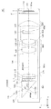
図1は、本発明に係る一実施形態のズームレンズを備える撮像装置としてのカメラモジュールを説明する断面図である。
[First Embodiment]
FIG. 1 is a cross-sectional view illustrating a camera module as an imaging apparatus including a zoom lens according to an embodiment of the present invention.
カメラモジュール(撮像装置)50は、被写体像を形成するズームレンズ10と、ズームレンズ10によって形成された被写体像を光電変換する撮像素子51と、この撮像素子51を背後から保持するとともに配線等を有する配線基板52と、ズームレンズ10等を保持するとともにズームレンズ10に物体側からの光線を入射させる開口部OPを有する鏡筒部54とを備える。ズームレンズ10は、被写体像を撮像素子51の撮像面(又は被投影面)Iに結像させる機能を有する。このカメラモジュール50は、後述する携帯端末に組み込まれて使用される。
The camera module (imaging device) 50 includes a
ズームレンズ10は、物体側から順に、第1レンズ群Gr1と、第2レンズ群Gr2と、第3レンズ群Gr3(開口絞りSを含む)と、第4レンズ群Gr4とを備える。このうち、レンズ群Gr1は、複数の負レンズを含み、各レンズ群Gr2〜Gr4は、単一又は複数のレンズからなるものとすることができる。第1レンズ群Gr1には、反射によって光路を折り曲げる三角柱状の反射光学素子(プリズムミラー)PRMが組み込まれており、−Z方向に向かう光線を傾斜した内面(又は反射面)12bで反射させることにより、90°折り曲げて+Y方向に向ける。つまり、光軸AXは、反射面12bを挟んで直交して延び、Y軸に平行な軸AX1とZ軸に平行な軸AX2とを有する。第1レンズ群Gr1において、反射光学素子PRMの物体側面12aは、凹面となっており、反射光学素子PRMの像側面12cは、平面となっている。なお、図1に例示したズームレンズ10は、後述する実施例1のズームレンズ11と同一の構成となっている。
The
撮像素子51は、固体撮像素子からなるセンサーチップである。撮像素子51の光電変換部51aは、CCD(電荷結合素子)やCMOS(相補型金属酸化物半導体)からなり、入射光をRGBの各画素毎に光電変換し、そのアナログ信号を出力する。受光部としての光電変換部51aの表面は、撮像面(被投影面)Iとなっている。
The
配線基板52は、支持体を介して撮像素子51を他の部材(例えば鏡筒部54)に対してアライメントして固定する役割を有する。配線基板52は、外部回路から撮像素子51や第1及び第2駆動機構55a,55bを駆動するための電圧や信号の供給を受けたり、また、検出信号を上記外部回路へ出力したりすることを可能としている。
The
撮像素子51のズームレンズ10側には、不図示のホルダー部材によって、例えばIRカットフィルター、光学的ローパスフィルター等で構成された平行平板Fが撮像素子51等を覆うように配置・固定されている。
On the
鏡筒部54は、ズームレンズ10を収納し保持している。鏡筒部54は、ズームレンズ10を構成するレンズ群Gr1〜Gr4のうち第2及び第3レンズ群Gr2,Gr3を光軸AXに沿って移動させることにより、ズームレンズ10の変倍及び合焦の動作を可能にするため、第1及び第2駆動機構55a,55bを有している。両駆動機構55a,55bは独立して動作可能であり、一方の第1駆動機構55aは、第2レンズ群Gr2を光軸AXに沿って往復移動させ、他方の第2駆動機構55bは、第3レンズ群Gr3を光軸AXに沿って往復移動させる。第1駆動機構55aは、例えばステッピングモーターと、タンジェントスクリュー型の動力伝達部材と、スライドガイドとを備える。また、第2駆動機構55bは、例えばボイスコイルモーターと、ガイドとを備える。なお、駆動機構は、上記に限るものでなく、第1駆動機構55aをステッピングモーターの代わりに圧電素子を用いたアクチュエーター(例えば、米国特許第5,589,723号参照)やボイスコイルモーター等で構成してもよいし、第2駆動機構55bをボイスコイルモーターの代わりに同様に圧電素子を用いたアクチュエーターやステッピングモーター等で構成してもよい。
The
以下、ズームレンズ10について詳細に説明する。図1のズームレンズ10は、撮像素子51の撮像面Iに被写体像を結像させるものであって、物体側より順に、負の屈折力を有する第1レンズ群Gr1と、正の屈折力を有する第2レンズ群Gr2と、負の屈折力を有する第3レンズ群Gr3と、正の屈折力を有する第4レンズ群Gr4とからなる。ここで、第1レンズ群Gr1は、例えば物体側面12aが凹面で像側面12cが平面の反射光学素子PRMと、両凹で負の第1レンズL11と、両凹で負の第2レンズL12と、両凸で正の第3レンズL13とを含む。ここで、第3レンズL13は、第2レンズL12に接合され、接合レンズL1bを形成している。第2レンズ群Gr2は、例えば開口絞りSと、両凸で正の第4レンズL21と、物体側に凸で負メニスカスの第5レンズL22と、両凸で正の第6レンズL23とを含む。ここで、第6レンズL23は、第5レンズL32に接合され、接合レンズL2bを形成している。第3レンズ群Gr3は、例えば略平凹で負の第7レンズL31を含む。第4レンズ群Gr4は、例えば像側に凸で正メニスカスの第8レンズL41を含む。なお、第4レンズL21、第7レンズL31、第8レンズL41等は、非球面レンズとすることができる。
Hereinafter, the
図1のズームレンズ10は、広角端から望遠端への変倍に際し、第1〜第4レンズ群Gr1〜Gr4のうち第2レンズ群Gr2と第3レンズ群Gr3の位置を変更する。具体的には、広角端から望遠端に至る変倍に際して、第1及び第4レンズ群Gr1,Gr4が撮像面I等を基準として固定されて移動せず、第2レンズ群Gr2が物体側に移動し、第3レンズ群Gr3も物体側に移動する。
The
図2(A)に示すように、反射光学素子PRMは、物体側面12aとして、略円形の凹面を有し、物体側面12aの周囲の有効領域外には、平面12fが形成されている。図2(B)に示すように、第8レンズL41は、小判形又は長円形の輪郭、すなわち小判形又は長円形の物体側面13aを有する。つまり、第8レンズL41では、光電変換部51aの撮像面Iに対応して、長辺側の両側がカッティングされ直線部(カッティング部)Cが設けられている。これにより、Z方向のズームレンズ10の厚みを極力薄くできる。
As shown in FIG. 2A, the reflective optical element PRM has a substantially circular concave surface as the
以上では、ズームレンズ10が、物体側から順に、第1レンズ群Gr1、第2レンズ群Gr2、第3レンズ群Gr3、及び第4レンズ群Gr4からなるとしたが、ズームレンズ10は、詳細な図示を省略するが、物体側から順に、第1レンズ群Gr1、第2レンズ群Gr2、及び第3レンズ群Gr3からなるものとできる。この場合、第1レンズ群Gr1が負の屈折力を有し第2レンズ群Gr2が正の屈折力を有するものとするが、第3レンズ群Gr3は、図1に示す第3レンズ群Gr3と異なるが図1に示す第4レンズ群Gr4と同様に正の屈折力を有するものとする。このようなズームレンズ10は、広角端から望遠端への変倍に際し、第2及び第3レンズ群Gr2,Gr3の位置を変更する。具体的には、広角端から望遠端に至る変倍に際して、第1レンズ群Gr1が撮像面I等を基準として固定されて移動させず、第2レンズ群Gr2を物体側に移動させ、第3レンズ群Gr3を一旦像側に移動させその後物体側に移動させる。なお、ズームレンズ10が第1〜第3レンズ群Gr1〜Gr3からなるものとする場合については、後述する実施例2が対応する。
In the above description, the
次に、図3、4A、及び4Bを参照して、図1に例示されるカメラモジュール50を搭載した携帯端末である携帯通信端末300の一例について説明する。
Next, an example of a
携帯通信端末300は、スマートフォン型の携帯通信端末であり、撮像装置であるカメラモジュール50を有する撮像機能部200と、各部を統括的に制御するとともに各処理に応じたプログラムを実行する制御部(CPU)310と、通信に関連するデータ、撮像した画像・映像等を表示するとともにユーザーの操作を受け付けるタッチパネルである表示操作部320と、電源スイッチ等を含む操作部330と、アンテナ341を介して外部サーバ等との間の各種情報通信を実現するための無線通信部340と、携帯通信端末300のシステムプログラムや各種処理プログラム及び端末ID等の必要な諸データを記憶している記憶部(ROM)360と、制御部310によって実行される各種処理プログラムやデータ、処理データ、若しくは撮像機能部200による撮像データ等を一時的に格納する作業領域として用いられる一時記憶部(RAM)370等を備えている。
The
撮像機能部200は、既に説明したカメラモジュール50のほかに、制御装置74、光学系駆動回路部105a、撮像素子駆動装置77、画像記憶装置78等を備える。
In addition to the
制御装置74は、撮像機能部200の各部を制御する。制御装置74は、CPU(Central Processing Unit)、RAM(Random Access Memory)、ROM(Read Only Memory)等を含み、ROMから読み出されてRAMに展開された各種プログラムとCPUとの協働で各種処理を実行する。なお、制御部310は、撮像機能部200の制御装置74と通信可能に接続されており、制御信号や画像データの授受が可能になっている。
The
光学系駆動回路部105aは、制御装置74の制御により変倍、合焦、露出等を行う際に、ズームレンズ10の第1及び第2駆動機構55a,55bを動作させてズームレンズ10の状態を制御する。光学系駆動回路部105aは、第1駆動機構55aを動作させて第2レンズ群Gr2を光軸AXに沿って適宜移動させるとともに、第2駆動機構55bを動作させて第3レンズ群Gr3を光軸AXに沿って適宜移動させることにより、ズームレンズ10にズーム動作を行わせる。つまり、ズーム動作に際して、第1及び第4レンズ群Gr1,Gr4は固定されている。広角端から望遠端に至る変倍に際して、第2レンズ群Gr2は、図1に対応するズームレンズ10の場合、物体側(図1の−Y側)に移動し、第3レンズ群Gr3も、物体側(図1の−Y側)に移動する。一方、ズームレンズ10は合焦動作も可能となっている。つまり、光学系駆動回路部105aは、第2駆動機構55bを動作させて第3レンズ群Gr3を光軸AXに沿って適宜移動させることにより、ズームレンズ10に合焦動作を行わせる。合焦動作に際して、第1、第2、及び第4レンズ群Gr1,Gr2,Gr4は固定されている。なお、ズームレンズ10が3群構成の場合、光学系駆動回路部105aは、例えば駆動機構55a,55bによって第2及び第3レンズ群を光軸AXに沿って移動させてズーム動作を行わせるとともに、第2駆動機構55bによって第3レンズ群Gr3を光軸AXに沿って移動させてズームレンズ10に合焦動作を行わせる。
The optical system
撮像素子駆動装置77は、制御装置74の制御により露出等を行う際に、撮像素子51の動作を制御する。具体的には、撮像素子駆動装置77は、タイミング信号に基づいて撮像素子51を走査駆動させてこれを制御する。また、撮像素子駆動装置77は、撮像素子51又はこれに付属する回路から送出された画像信号に対して、歪み補正、色補正、圧縮等の各種画像処理を施すことができる。
The image
画像記憶装置78は、デジタル化された画像信号を撮像素子駆動装置77から受け取って、読み出し及び書き込み可能な画像データとして記憶する。
The
ここで、上記撮像機能部200を含む携帯通信端末300の撮影動作を説明する。携帯通信端末300をカメラとして動作させるカメラモードに設定されると、被写体のモニタリング(スルー画像表示)と、画像撮影実行とが行われる。モニタリングにおいては、ズームレンズ10を介して得られた被写体の像が、撮像素子51の撮像面I(図1等参照)に結像される。撮像素子51は、撮像素子駆動装置77によって走査駆動され、一定周期毎に結像した光像に対応する光電変換出力としてのアナログ信号を1画面分出力する。
Here, the photographing operation of the
このアナログ信号は、撮像素子51に付属する回路においてRGBの各原色成分毎に適宜ゲイン調整された後に、デジタルデータに変換される。そのデジタルデータに対しては、撮像素子駆動装置77にて画素補間処理及びY補正処理を含むカラープロセス処理が行なわれて、デジタル値の輝度信号Y及び色差信号Cb,Cr(画像データ)が生成されて画像記憶装置78に格納される。格納されたデジタルデータは、画像記憶装置78から定期的に読み出されてそのビデオ信号が生成されて、制御装置74及び制御部310を介して、表示操作部320に出力される。
This analog signal is converted into digital data after gain adjustment is appropriately performed for each primary color component of RGB in a circuit attached to the
この表示操作部320は、モニタリングにおいては電子ファインダーとして機能し、撮像画像をリアルタイムに表示することとなる。この状態で、随時、ユーザーが表示操作部320を介して行う操作入力に基づいて、光学系駆動回路部105aの駆動によりズームレンズ10の変倍、合焦、露出等が設定される。
The
このようなモニタリング状態において、ユーザーが表示操作部320を適宜操作することにより、静止画像データが撮影される。表示操作部320の操作内容に応じて、画像記憶装置78に格納された1コマの画像データが読み出されて、撮像素子駆動装置77により圧縮される。その圧縮された画像データは、制御装置74及び制御部310を介して、例えばフラッシュメモリーその他の補助記憶部(不図示)に記録される。
In such a monitoring state, when the user appropriately operates the
なお、上述の撮像機能部200は、本発明に好適な構成の一例であり、本発明は、これに限定されるものではない。
The above-described
すなわち、ズームレンズ10を搭載した撮像装置であるカメラモジュール50は、スマートフォン型の携帯通信端末300に内蔵されるものに限らず、携帯電話、PHS(Personal Handyphone System)等に内蔵されるものであってもよく、PDA(Personal Digital Assistant)、タブレットパソコン、モバイルパソコン、デジタルスチルカメラ、ビデオカメラ等に内蔵されるであってもよい。
In other words, the
以下、図1に示す実施形態のズームレンズ10が満たす数値的な条件について説明する。図1のズームレンズ10は、既に説明した条件式(1)
1.7<n1n1<2.1 … (1)
を満足する。ここで、値n1n1は、反射光学素子PRMの像側のレンズのうち、最も物体側にあるレンズL11の屈折率を示す。
Hereinafter, numerical conditions satisfied by the
1.7 <n1n1 <2.1 (1)
Satisfied. Here, the value n1n1 indicates the refractive index of the lens L11 closest to the object side among the lenses on the image side of the reflective optical element PRM.
実施形態のズームレンズ10は、上記条件式(1)に加えて、既に説明した条件式(2)
30<ν1n2−ν1p1<65 … (2)
を満足する。ただし、値ν1n2は、第1レンズ群Gr1の接合レンズL1bのうち、負の屈折力を有するレンズL12のアッベ数を示し、値ν1p1は、第1レンズ群Gr1の接合レンズL1bのうち、正の屈折力L13を有するレンズのアッベ数を示す。
In the
30 <ν1n2-ν1p1 <65 (2)
Satisfied. However, the value ν1n2 indicates the Abbe number of the lens L12 having negative refractive power among the cemented lenses L1b of the first lens group Gr1, and the value ν1p1 is a positive value among the cemented lenses L1b of the first lens group Gr1. The Abbe number of a lens having a refractive power L13 is shown.
実施形態のズームレンズ10は、上記条件式(1)等に加えて、既に説明した条件式(3)
0.4<d11/fW<0.9 … (3)
を満足する。ただし、値d11は、反射光学素子PRMの物体側面12a(第1レンズ群Gr1の最も物体側の面)の頂点12mから反射光学素子の反射面12bと光軸AXとの交点12nまでの距離を示し、値fWは、広角端におけるズームレンズ10全系の焦点距離を示す。
In the
0.4 <d11 / fW <0.9 (3)
Satisfied. However, the value d11 is the distance from the
実施形態のズームレンズ10は、上記条件式(1)等に加えて、既に説明した条件式(4)
−4.0<r1/d1<−2.0 … (4)
を満足する。ただし、値r1は、反射光学素子PRMの物体側面12aの近軸曲率半径を示し、値d1は、反射光学素子PRMの物体側面12aから像側面12cまでの光軸AX上の距離d11+d12を示す。
In the
-4.0 <r1 / d1 <-2.0 (4)
Satisfied. However, the value r1 indicates the paraxial radius of curvature of the
実施形態のズームレンズ10は、上記条件式(1)等に加えて、既に説明した条件式(5)
1.80<nprm<2.20 … (5)
を満足する。ただし、値nprmは、反射光学素子PRMの屈折率を示す。
In the
1.80 <nprm <2.20 (5)
Satisfied. However, the value nprm indicates the refractive index of the reflective optical element PRM.
実施形態のズームレンズ10は、上記条件式(1)等に加えて、既に説明した条件式(6)
23<νprm<50 … (6)
を満足する。ただし、値nprmは、反射光学素子PRMを本体材料(内面反射させる屈折媒体)のアッベ数を示す。
In the
23 <νprm <50 (6)
Satisfied. However, the value nprm indicates the Abbe number of the main body material (refractive medium that internally reflects the reflective optical element PRM).
〔実施例〕
以下、本発明に係るズームレンズの実施例を示す。各実施例に使用する記号は下記の通りである。
f :ズームレンズ全系の焦点距離
Fno:Fナンバー
2Y :固体撮像素子の撮像面対角線長
R :近軸曲率半径
D :軸上面間隔
Nd :レンズ材料のd線に対する屈折率
νd :レンズ材料のアッベ数
d11:反射光学素子の物体側面の頂点から反射光学素子の反射面と光軸との交点までの距離
〔Example〕
Examples of the zoom lens according to the present invention will be described below. Symbols used in each example are as follows.
f: Focal length of the entire zoom lens system Fno: F number 2Y: Diagonal length of the imaging surface of the solid-state imaging device R: Paraxial radius of curvature D: Spacing on the axial surface Nd: Refractive index νd of lens material with respect to d-line: Abbe of lens material Number d11: distance from the vertex of the object side surface of the reflecting optical element to the intersection of the reflecting surface of the reflecting optical element and the optical axis
各実施例において、各面番号(Surf.N)の後に「*」が記載されている面が非球面形状を有する面であり、非球面の形状は、面の頂点を原点とし、光軸方向にX軸をとり、光軸と垂直方向の高さをhとして以下の「数1」で表す。その他、記号inf.は、無限大又は∞を意味し、記号stopは、絞りを意味する。
〔数1〕

Ai:i次の非球面係数
R :曲率半径
K :円錐定数
In each embodiment, the surface described with “*” after each surface number (Surf.N) is a surface having an aspherical shape, and the aspherical shape has the apex of the surface as the origin and the optical axis direction. Is expressed by the following “Equation 1” where the height in the direction perpendicular to the optical axis is h. In addition, the symbol inf. Means infinity or ∞, and the symbol stop means aperture.
[Equation 1]
Ai: i-order aspheric coefficient R: radius of curvature K: conic constant
以下、本発明のズームレンズの具体的な実施例を説明する。 Specific examples of the zoom lens according to the present invention will be described below.
〔実施例1〕
実施例1のズームレンズの基本的な特徴は以下のようなものである。
ズーム比=2.85
レンズ全長=26.597
d11=2.48
[Example 1]
The basic features of the zoom lens of Example 1 are as follows.
Zoom ratio = 2.85
Total lens length = 26.597
d11 = 2.48
実施例1のレンズデータを表1に示す。なお、これ以降(表のレンズデータを含む)において、10のべき乗数(例えば2.5×10−02)をE(例えば2.5E−02)を用いて表すものとする。
〔表1〕
[曲率半径、面間隔等]
Surf.N R(mm) D(mm) Nd νd 有効半径(mm)
1 -14.220 5.380 2.00100 29.1 2.86
2 inf. 0.289 2.01
3 -11.007 0.400 1.88300 40.8 1.98
4 50.279 0.272 1.96
5 -14.495 0.400 1.49700 81.6 1.96
6 21.909 0.010 1.51400 42.8 1.99
7 21.909 0.835 1.92290 20.9 1.99
8 -20.134 gd1 2.00
9(stop) inf. 0.250 2.01
10* 5.898 1.830 1.72900 54.0 2.18
11* -20.136 0.332 2.18
12 10.525 0.600 2.00070 25.5 2.13
13 4.307 0.010 1.51400 42.8 2.00
14 4.307 1.766 1.49710 81.6 2.00
15* -10.055 0.150 1.98
16 inf. gd2 1.94
17* 108.890 0.527 1.54470 56.2 1.85
18* 4.002 gd3 1.82
19* -15.701 1.706 1.54470 56.2 2.96
20* -4.479 2.391 3.11
21 inf. 0.210 1.51680 64.2 2.98
22 inf. 0.640 2.97
[非球面係数]
第10面
K=0.00000E+00, A4=-0.76329E-03, A6=0.12221E-03,
A8=-0.87163E-04, A10=0.17294E-04, A12=-0.13459E-05
第11面
K=0.00000E+00, A4=0.62456E-03, A6=0.79378E-04,
A8=-0.10405E-03, A10=0.22536E-04, A12=-0.18276E-05
第15面
K=0.00000E+00, A4=0.56987E-03, A6=-0.17855E-03,
A8=0.20075E-03, A10=-0.56274E-04, A12=0.55828E-05,
第17面
K=0.00000E+00, A4=-0.18863E-02, A6=0.21678E-02,
A8=-0.10897E-02, A10=0.13615E-03, A12=0.24439E-04,
A14=-0.52397E-05
第18面
K=0.00000E+00, A4=-0.27319E-02, A6=0.34476E-02,
A8=-0.21257E-02, A10=0.53285E-03, A12=-0.49042E-04,
A14=-0.97401E-07
第19面
K=0.00000E+00, A4=-0.91837E-03, A6=0.22291E-03,
A8=0.13428E-07, A10=-0.15372E-05, A12=0.10398E-06
第20面
K=0.00000E+00, A4=0.15697E-02, A6=0.28684E-04,
A8=0.24545E-04, A10=-0.28292E-05, A12=0.12938E-06
Table 1 shows lens data of Example 1. In the following (including the lens data in the table), a power of 10 (for example, 2.5 × 10 −02 ) is expressed using E (for example, 2.5E-02).
[Table 1]
[Curvature radius, surface spacing, etc.]
Surf.NR (mm) D (mm) Nd νd Effective radius (mm)
1 -14.220 5.380 2.00100 29.1 2.86
2 inf. 0.289 2.01
3 -11.007 0.400 1.88300 40.8 1.98
4 50.279 0.272 1.96
5 -14.495 0.400 1.49700 81.6 1.96
6 21.909 0.010 1.51400 42.8 1.99
7 21.909 0.835 1.92290 20.9 1.99
8 -20.134 gd1 2.00
9 (stop) inf. 0.250 2.01
10 * 5.898 1.830 1.72900 54.0 2.18
11 * -20.136 0.332 2.18
12 10.525 0.600 2.00070 25.5 2.13
13 4.307 0.010 1.51400 42.8 2.00
14 4.307 1.766 1.49710 81.6 2.00
15 * -10.055 0.150 1.98
16 inf.gd2 1.94
17 * 108.890 0.527 1.54470 56.2 1.85
18 * 4.002 gd3 1.82
19 * -15.701 1.706 1.54470 56.2 2.96
20 * -4.479 2.391 3.11
21 inf. 0.210 1.51680 64.2 2.98
22 inf. 0.640 2.97
[Aspheric coefficient]
10th page
K = 0.00000E + 00, A4 = -0.76329E-03, A6 = 0.12221E-03,
A8 = -0.87163E-04, A10 = 0.17294E-04, A12 = -0.13459E-05
11th page
K = 0.00000E + 00, A4 = 0.62456E-03, A6 = 0.79378E-04,
A8 = -0.10405E-03, A10 = 0.22536E-04, A12 = -0.18276E-05
15th page
K = 0.00000E + 00, A4 = 0.56987E-03, A6 = -0.17855E-03,
A8 = 0.20075E-03, A10 = -0.56274E-04, A12 = 0.55828E-05,
17th page
K = 0.00000E + 00, A4 = -0.18863E-02, A6 = 0.21678E-02,
A8 = -0.10897E-02, A10 = 0.13615E-03, A12 = 0.24439E-04,
A14 = -0.52397E-05
18th page
K = 0.00000E + 00, A4 = -0.27319E-02, A6 = 0.34476E-02,
A8 = -0.21257E-02, A10 = 0.53285E-03, A12 = -0.49042E-04,
A14 = -0.97401E-07
19th page
K = 0.00000E + 00, A4 = -0.91837E-03, A6 = 0.22291E-03,
A8 = 0.13428E-07, A10 = -0.15372E-05, A12 = 0.10398E-06
20th page
K = 0.00000E + 00, A4 = 0.15697E-02, A6 = 0.28684E-04,
A8 = 0.24545E-04, A10 = -0.28292E-05, A12 = 0.12938E-06
実施例1のズームレンズの各ポジション(Po)1〜3における全系の焦点距離(f)、Fナンバー(Fno)、画角、撮像面対角長(2Y)、及び群間隔(gd1〜gd3)を以下の表2に示す。なお、Po=1は、広角端であり、Po=2は、中間であり、Po=3は、望遠端である。
〔表2〕
Po f Fno 画角 2Y
1 4.76 2.88 63.4 5.002
2 7.94 3.86 40.7 5.742
3 13.58 5.02 23.9 5.888
Po gd1 gd2 gd3
1 6.856 1.812 1.932
2 3.458 2.161 4.981
3 0.150 4.085 6.365
The focal length (f) of the entire system at each position (Po) 1 to 3 of the zoom lens according to the first embodiment, the F number (Fno), the angle of view, the diagonal length of the imaging surface (2Y), and the group interval (gd1 to gd3). ) Is shown in Table 2 below. Note that Po = 1 is the wide-angle end, Po = 2 is the middle, and Po = 3 is the telephoto end.
[Table 2]
Po f Fno angle of view 2Y
1 4.76 2.88 63.4 5.002
2 7.94 3.86 40.7 5.742
3 13.58 5.02 23.9 5.888
Po gd1 gd2 gd3
1 6.856 1.812 1.932
2 3.458 2.161 4.981
3 0.150 4.085 6.365
実施例1のズームレンズの各レンズ群のデータ以下の表3に示す。
〔表3〕
レンズ群 始面 焦点距離(mm)
1 1 -7.10
2 9 5.75
3 17 -7.64
4 19 10.92
Data of each lens group of the zoom lens of Example 1 is shown in Table 3 below.
[Table 3]
Lens group Start surface Focal length (mm)
1 1 -7.10
2 9 5.75
3 17 -7.64
4 19 10.92
図5は、実施例1のズームレンズの断面図である。実施例1のズームレンズ11は、物体側より順に、第1レンズ群Gr1と、第2レンズ群Gr2と、第3レンズ群Gr3と、第4レンズ群Gr4とからなる。ここで、第1レンズ群Gr1は、物体側に凹面が形成された直角プリズムである反射光学素子PRMと、両凹で負の第1レンズL11と、両凹で負の第2レンズL12と、両凸で正の第3レンズL13とを含む。このうち、反射光学素子PRMは、その物体側面12aに物体側から入射した光線を直角に折り曲げることのできる直角型のプリズムである。また、第2レンズL12と第3レンズL13とは、接合レンズとなっている。第2レンズ群Gr2は、開口絞りSと、両凸で正の第4レンズL21と、物体側に凸で負メニスカスの第5レンズL22と、両凸で正の第6レンズL23とを含む。このうち、第5レンズL22と第6レンズL23とは、接合レンズとなっている。第3レンズ群Gr3は、平凹に近いが物体側に凸で負メニスカスの第7レンズL31を含む。第4レンズ群Gr4は、像側に凸で正メニスカスの第8レンズL41を含む。その他、符号Fは、光学的ローパスフィルター、IRカットフィルター、固体撮像素子のシールガラス等を想定した平行平板を示す。また、符号Iは、撮像素子51の被投影面である撮像面を示す。これらの平行平板F及び撮像面Iについては、以下で説明する実施例2、3でも同様であり、今後は説明を省略する。
FIG. 5 is a sectional view of the zoom lens of Example 1. FIG. The
図6A〜6Cは、実施例1のズームレンズ11のズーム動作の際のポジションをそれぞれ示している。すなわち、図6Aはズームレンズ11の広角端における断面図であり、図6Bは中間における断面図であり、図6Cは望遠端における断面図である。なお、この実施例1及び以下の実施例において、反射光学素子PRMは、その光路長と等価で回転対称な形状を有する凹平の単レンズとして表されている。
6A to 6C respectively show the positions of the
図7Aは、ズームレンズ11の広角端における収差図(球面収差、非点収差、及び歪曲収差)であり、図7Bは、中間における収差図(球面収差、非点収差、及び歪曲収差)であり、図7Cは、望遠端における収差図(球面収差、非点収差、及び歪曲収差)である。なお、上記収差図及び以後の収差図において、球面収差図では、実線がd線を表し、点線がg線を表すものとし、非点収差図では、実線がサジタル像面を表し、点線がメリジオナル像面を表すものとする。
FIG. 7A is an aberration diagram (spherical aberration, astigmatism, and distortion aberration) at the wide-angle end of the
実施例1のズームレンズ11は、広角端から望遠端への変倍に際し、第2レンズ群Gr2が光軸AX方向に沿って物体側に移動し、かつ、第3レンズ群Gr3が光軸AX方向に沿って物体側に移動する。他のレンズ群Gr1,Gr4は、変倍に際し固定されており、各レンズ群Gr1〜Gr4の間隔を変えることにより変倍を行うことができる。また、第3レンズ群Gr3を移動させることによって無限遠から有限距離への合焦を行うことができる。なお、第4及び第6レンズL21,L23は、ガラスモールドレンズ、第7及び第8レンズL31,L41は、プラスチックレンズ、それ以外のレンズは、ガラス材料による研磨レンズを想定している。
In the
〔実施例2〕
実施例2のズームレンズの基本的な特徴は以下のようなものである。
ズーム比=2.86
レンズ全長=25.722
d11=2.573
[Example 2]
The basic features of the zoom lens of Example 2 are as follows.
Zoom ratio = 2.86
Total lens length = 25.722
d11 = 2.573
実施例2のレンズデータを表4に示す。
〔表4〕
[曲率半径、面間隔等]
surf.N R(mm) D(mm) Nd νd 有効半径(mm)
1 -15.964 5.573 2.00100 29.1 3.08
2 inf. 0.248 2.17
3 -15.428 0.400 1.92290 20.9 2.14
4 22.433 0.405 2.08
5 -13.249 0.445 1.59350 67.0 2.07
6 10.956 0.010 1.51400 42.8 2.07
7 10.956 1.011 1.92290 20.9 2.07
8* -19.241 gd1 2.05
9(stop) inf. 0.000 1.91
10* 3.448 1.826 1.55330 71.7 2.05
11* -5.644 1.096 2.01
12 27.513 0.600 2.00100 29.1 1.59
13 2.130 0.010 1.51400 42.8 1.41
14 2.130 2.000 1.88200 37.2 1.41
15* 3.452 gd2 1.20
16* 8.487 1.200 1.90270 31.0 2.95
17* 17.319 gd3 2.92
18 inf. 0.210 1.51680 64.2 2.86
19 inf. 0.100 2.87
[非球面係数]
第8面
K=0.00000E+00, A4=-0.41440E-03, A6=0.27136E-03,
A8=-0.75125E-04, A10=0.87893E-05, A12=-0.17903E-06
第10面
K=0.00000E+00, A4=-0.36785E-02, A6=-0.61427E-04,
A8=-0.20845E-04, A10=-0.66845E-05
第11面
K=0.00000E+00, A4=0.38619E-02, A6=-0.27218E-03,
A8=-0.31015E-05, A10=-0.46493E-05
第15面
K=0.00000E+00, A4=-0.84124E-03, A6=0.40339E-02,
A8=-0.41822E-02, A10=0.28159E-02, A12=-0.68662E-03
第16面
K=0.00000E+00, A4=-0.13295E-02, A6=-0.13300E-02,
A8=0.35712E-03, A10=-0.32673E-04, A12=0.10650E-05
第17面
K=0.00000E+00, A4=-0.22083E-02, A6=-0.15464E-02,
A8=0.38031E-03, A10=-0.32553E-04, A12=0.96962E-06
Table 4 shows lens data of Example 2.
[Table 4]
[Curvature radius, surface spacing, etc.]
surf.NR (mm) D (mm) Nd νd Effective radius (mm)
1 -15.964 5.573 2.00100 29.1 3.08
2 inf. 0.248 2.17
3 -15.428 0.400 1.92290 20.9 2.14
4 22.433 0.405 2.08
5 -13.249 0.445 1.59350 67.0 2.07
6 10.956 0.010 1.51400 42.8 2.07
7 10.956 1.011 1.92290 20.9 2.07
8 * -19.241 gd1 2.05
9 (stop) inf. 0.000 1.91
10 * 3.448 1.826 1.55330 71.7 2.05
11 * -5.644 1.096 2.01
12 27.513 0.600 2.00100 29.1 1.59
13 2.130 0.010 1.51400 42.8 1.41
14 2.130 2.000 1.88200 37.2 1.41
15 * 3.452 gd2 1.20
16 * 8.487 1.200 1.90270 31.0 2.95
17 * 17.319 gd3 2.92
18 inf. 0.210 1.51680 64.2 2.86
19 inf.0.100 2.87
[Aspheric coefficient]
8th page
K = 0.00000E + 00, A4 = -0.41440E-03, A6 = 0.27136E-03,
A8 = -0.75125E-04, A10 = 0.87893E-05, A12 = -0.17903E-06
10th page
K = 0.00000E + 00, A4 = -0.36785E-02, A6 = -0.61427E-04,
A8 = -0.20845E-04, A10 = -0.66845E-05
11th page
K = 0.00000E + 00, A4 = 0.38619E-02, A6 = -0.27218E-03,
A8 = -0.31015E-05, A10 = -0.46493E-05
15th page
K = 0.00000E + 00, A4 = -0.84124E-03, A6 = 0.40339E-02,
A8 = -0.41822E-02, A10 = 0.28159E-02, A12 = -0.68662E-03
16th page
K = 0.00000E + 00, A4 = -0.13295E-02, A6 = -0.13300E-02,
A8 = 0.35712E-03, A10 = -0.32673E-04, A12 = 0.10650E-05
17th page
K = 0.00000E + 00, A4 = -0.22083E-02, A6 = -0.15464E-02,
A8 = 0.38031E-03, A10 = -0.32553E-04, A12 = 0.96962E-06
実施例2のズームレンズの各ポジション(Po)1〜3における全系の焦点距離(f)、Fナンバー(Fno)、画角、撮像面対角長(2Y)、及び群間隔等(gd1〜gd3)を以下の表5に示す。なお、Po=1は、広角端であり、Po=2は、中間であり、Po=3は、望遠端である。
〔表5〕
Po f Fno 画角 2Y
1 4.74 2.88 63.6 5.010
2 8.04 4.09 40.2 5.642
3 13.58 5.38 24.5 5.719
Po gd1 gd2 gd3
1 6.52 2.45 1.62
2 3.63 6.01 0.95
3 0.30 1.71 8.58
The focal length (f) of the entire system at each position (Po) 1 to 3 of the zoom lens according to the second embodiment, the F number (Fno), the angle of view, the diagonal length of the imaging surface (2Y), the group interval, and the like (gd1 to gd3) is shown in Table 5 below. Note that Po = 1 is the wide-angle end, Po = 2 is the middle, and Po = 3 is the telephoto end.
[Table 5]
Po f Fno angle of view 2Y
1 4.74 2.88 63.6 5.010
2 8.04 4.09 40.2 5.642
3 13.58 5.38 24.5 5.719
Po gd1 gd2 gd3
1 6.52 2.45 1.62
2 3.63 6.01 0.95
3 0.30 1.71 8.58
実施例2のズームレンズの各レンズ群のデータ以下の表6に示す。
〔表6〕
レンズ群 始面 焦点距離(mm)
1 1 -7.66
2 9 5.65
3 16 17.32
Data for each lens group of the zoom lens of Example 2 is shown in Table 6 below.
[Table 6]
Lens group Start surface Focal length (mm)
1 1 -7.66
2 9 5.65
3 16 17.32
図8A〜8Cは、実施例2のズームレンズの断面図であり、実施例2のズームレンズ12のズーム動作の際のポジションをそれぞれ示している。すなわち、図8Aはズームレンズ12の広角端における断面図であり、図8Bは中間における断面図であり、図8Cは望遠端における断面図である。
8A to 8C are cross-sectional views of the zoom lens according to the second embodiment, and illustrate positions during the zoom operation of the
実施例2のズームレンズ12は、物体側より順に、第1レンズ群Gr1と、第2レンズ群Gr2と、第3レンズ群Gr3とからなる。ここで、第1レンズ群Gr1は、物体側に凹面が形成された直角プリズムである反射光学素子PRMと、両凹で負の第1レンズL11と、両凹で負の第2レンズL12と、両凸で正の第3レンズL13とを含む。このうち、反射光学素子PRMは、その物体側面12aに物体側から入射した光線を直角に折り曲げることのできる直角型のプリズムである。また、第2レンズL12と第3レンズL13とは、接合レンズとなっている。第2レンズ群Gr2は、開口絞りSと、両凸で正の第4レンズL21と、物体側に凸で負メニスカスの第5レンズL22と、物体側に凸で正メニスカスの第6レンズL23とを含む。このうち、第5レンズL22と第6レンズL23とは、接合レンズとなっている。第3レンズ群Gr3は、凸平に近いが物体側に凸で負メニスカスの第7レンズL31を含む。ズームレンズ12は、その他、フィルター等である平行平板Fを含む。
The
図9Aは、ズームレンズ12の広角端における収差図(球面収差、非点収差、及び歪曲収差)であり、図9Bは、中間における収差図(球面収差、非点収差、及び歪曲収差)であり、図9Cは、望遠端における収差図(球面収差、非点収差、及び歪曲収差)である。
9A is an aberration diagram (spherical aberration, astigmatism, and distortion aberration) at the wide-angle end of the
実施例2のズームレンズ12は、広角端から望遠端への変倍に際し、第2レンズ群Gr2が光軸AX方向に沿って物体側に移動し、かつ、第3レンズ群Gr3が光軸AX方向に沿って一旦像側に僅かに移動した後に物体側に移動する。他のレンズ群Gr1は、変倍に際し固定されており、各レンズ群Gr1〜Gr3の間隔を変えることにより変倍を行うことができる。また、第3レンズ群Gr3を移動させることによって無限遠から有限距離への合焦を行うことができる。なお第1、第3、第4、第6、及び第7レンズL11,L13,L21,L23,L31は、ガラスモールドレンズ、それ以外のレンズは、ガラス材料による研磨レンズを想定している。
In the
〔実施例3〕
実施例3のズームレンズの基本的な特徴は以下のようなものである。
ズーム比=2.85
レンズ全長=29.799
d11=2.810
Example 3
The basic features of the zoom lens of Example 3 are as follows.
Zoom ratio = 2.85
Total lens length = 29.799
d11 = 2.810
実施例3のレンズデータを表7に示す。
〔表7〕
[曲率半径、面間隔等]
Surf.N R(mm) D(mm) Nd νd 有効半径(mm)
1 -19.922 6.022 1.88100 40.1 3.39
2 inf. 0.329 2.18
3 -10.797 0.400 1.91082 35.3 2.13
4 32.208 0.383 2.08
5 -18.139 0.600 1.49700 81.6 2.06
6 18.207 0.010 1.51400 42.8 2.03
7 18.207 0.828 1.92286 20.9 2.03
8 -29.659 gd1 2.00
9(stop) inf. 0.000 1.99
10* 6.317 1.797 1.72903 54.0 2.08
11* -25.113 0.459 2.09
12 12.357 0.400 1.84666 23.8 2.05
13 4.816 0.010 1.51400 42.8 1.98
14 4.816 1.685 1.49710 81.6 1.98
15* -9.436 0.150 1.96
16 inf. gd2 1.92
17* 867.545 0.600 1.54470 56.2 1.83
18* 4.125 gd3 1.81
19* -19.559 1.679 1.54470 56.2 2.99
20* -4.794 2.577 3.13
21 inf. 0.210 1.51680 64.2 2.98
22 inf. 0.640 2.97
[非球面係数]
第10面
K=0.00000E+00, A4=-0.55874E-03, A6=0.11736E-03,
A8=-0.86892E-04, A10=0.17973E-04, A12=-0.14760E-05
第11面
K=0.00000E+00, A4=0.62200E-03, A6=0.60228E-04,
A8=-0.97981E-04, A10=0.21680E-04, A12=-0.18463E-05
第15面
K=0.00000E+00, A4=0.74033E-03, A6=-0.83221E-04,
A8=0.14025E-03, A10=-0.38797E-04, A12=0.38536E-05
第17面
K=0.00000E+00, A4=-0.20482E-02, A6=0.20319E-02,
A8=-0.99136E-03, A10=0.13594E-03, A12=0.21331E-04,
A14=-0.52397E-05
第18面
K=0.00000E+00, A4=-0.26571E-02, A6=0.29448E-02,
A8=-0.18182E-02, A10=0.47887E-03, A12=-0.47099E-04,
A14=-0.97401E-07
第19面
K=0.00000E+00, A4=-0.51998E-03, A6=0.17546E-03,
A8=-0.98627E-06, A10=-0.13045E-05, A12=0.80632E-07
第20面
K=0.00000E+00, A4=0.15930E-02, A6=0.94073E-05,
A8=0.22080E-04, A10=-0.25856E-05, A12=0.10389E-06
Table 7 shows lens data of Example 3.
[Table 7]
[Curvature radius, surface spacing, etc.]
Surf.NR (mm) D (mm) Nd νd Effective radius (mm)
1 -19.922 6.022 1.88100 40.1 3.39
2 inf. 0.329 2.18
3 -10.797 0.400 1.91082 35.3 2.13
4 32.208 0.383 2.08
5 -18.139 0.600 1.49700 81.6 2.06
6 18.207 0.010 1.51400 42.8 2.03
7 18.207 0.828 1.92286 20.9 2.03
8 -29.659 gd1 2.00
9 (stop) inf. 0.000 1.99
10 * 6.317 1.797 1.72903 54.0 2.08
11 * -25.113 0.459 2.09
12 12.357 0.400 1.84666 23.8 2.05
13 4.816 0.010 1.51400 42.8 1.98
14 4.816 1.685 1.49710 81.6 1.98
15 * -9.436 0.150 1.96
16 inf.gd2 1.92
17 * 867.545 0.600 1.54470 56.2 1.83
18 * 4.125 gd3 1.81
19 * -19.559 1.679 1.54470 56.2 2.99
20 * -4.794 2.577 3.13
21 inf. 0.210 1.51680 64.2 2.98
22 inf. 0.640 2.97
[Aspheric coefficient]
10th page
K = 0.00000E + 00, A4 = -0.55874E-03, A6 = 0.11736E-03,
A8 = -0.86892E-04, A10 = 0.17973E-04, A12 = -0.14760E-05
11th page
K = 0.00000E + 00, A4 = 0.62200E-03, A6 = 0.60228E-04,
A8 = -0.97981E-04, A10 = 0.21680E-04, A12 = -0.18463E-05
15th page
K = 0.00000E + 00, A4 = 0.74033E-03, A6 = -0.83221E-04,
A8 = 0.14025E-03, A10 = -0.38797E-04, A12 = 0.38536E-05
17th page
K = 0.00000E + 00, A4 = -0.20482E-02, A6 = 0.20319E-02,
A8 = -0.99136E-03, A10 = 0.13594E-03, A12 = 0.21331E-04,
A14 = -0.52397E-05
18th page
K = 0.00000E + 00, A4 = -0.26571E-02, A6 = 0.29448E-02,
A8 = -0.18182E-02, A10 = 0.47887E-03, A12 = -0.47099E-04,
A14 = -0.97401E-07
19th page
K = 0.00000E + 00, A4 = -0.51998E-03, A6 = 0.17546E-03,
A8 = -0.98627E-06, A10 = -0.13045E-05, A12 = 0.80632E-07
20th page
K = 0.00000E + 00, A4 = 0.15930E-02, A6 = 0.94073E-05,
A8 = 0.22080E-04, A10 = -0.25856E-05, A12 = 0.10389E-06
実施例3のズームレンズの各ポジション(Po)1〜3における全系の焦点距離(f)、Fナンバー(Fno)、画角、撮像面対角長(2Y)、及び群間隔(gd1〜gd3)を以下の表2に示す。なお、Po=1は、広角端であり、Po=2は、中間であり、Po=3は、望遠端である。
〔表8〕
Po f Fno 画角 2Y
1 4.76 2.88 63.4 5.001
2 7.94 3.86 40.7 5.748
3 13.58 5.04 23.9 5.888
Po gd1 gd2 gd3
1 7.334 1.820 1.868
2 3.817 2.100 5.105
3 0.400 3.800 6.822
The focal length (f) of the entire system at each position (Po) 1 to 3 of the zoom lens according to the third embodiment, the F number (Fno), the angle of view, the diagonal length of the imaging surface (2Y), and the group interval (gd1 to gd3). ) Is shown in Table 2 below. Note that Po = 1 is the wide-angle end, Po = 2 is the middle, and Po = 3 is the telephoto end.
[Table 8]
Po f Fno angle of view 2Y
1 4.76 2.88 63.4 5.001
2 7.94 3.86 40.7 5.748
3 13.58 5.04 23.9 5.888
Po gd1 gd2 gd3
1 7.334 1.820 1.868
2 3.817 2.100 5.105
3 0.400 3.800 6.822
実施例3のズームレンズの各レンズ群のデータ以下の表9に示す。
〔表9〕
レンズ群 始面 焦点距離(mm)
1 1 -7.45
2 9 5.78
3 17 -7.61
4 19 11.21
Data for each lens group of the zoom lens of Example 3 is shown in Table 9 below.
[Table 9]
Lens group Start surface Focal length (mm)
1 1 -7.45
2 9 5.78
3 17 -7.61
4 19 11.21
図10A〜10Cは、実施例のズームレンズ13の断面図であり、実施例3のズームレンズ13のズーム動作の際のポジションをそれぞれ示している。すなわち、図10Aはズームレンズ13の広角端における断面図であり、図10Bは中間における断面図であり、図10Cは望遠端における断面図である。
10A to 10C are cross-sectional views of the
実施例3のズームレンズ13は、物体側より順に、第1レンズ群Gr1と、第2レンズ群Gr2と、第3レンズ群Gr3と、第4レンズ群Gr4とからなる。ここで、第1レンズ群Gr1は、物体側に凹面が形成された直角プリズムである反射光学素子PRMと、両凹で負の第1レンズL11と、両凹で負の第2レンズL12と、両凸で正の第3レンズL13とを含む。このうち、反射光学素子PRMは、その物体側面12aに物体側から入射した光線を直角に折り曲げることのできる直角型のプリズムである。また、第2レンズL12と第3レンズL13とは、接合レンズとなっている。第2レンズ群Gr2は、開口絞りSと、両凸で正の第4レンズL21と、物体側に凸で負メニスカスの第5レンズL22と、両凸で正の第6レンズL23とを含む。このうち、第5レンズL22と第6レンズL23とは、接合レンズとなっている。第3レンズ群Gr3は、平凹に近いが物体側に凸で負メニスカスの第7レンズL31を含む。第4レンズ群Gr4は、像側に凸で正メニスカスの第8レンズL41を含む。ズームレンズ13は、その他、フィルター等である平行平板Fを含む。
The
図11Aは、ズームレンズ13の広角端における収差図(球面収差、非点収差、及び歪曲収差)であり、図11Bは、中間における収差図(球面収差、非点収差、及び歪曲収差)であり、図11Cは、望遠端における収差図(球面収差、非点収差、及び歪曲収差)である。
FIG. 11A is an aberration diagram (spherical aberration, astigmatism, and distortion aberration) at the wide-angle end of the
実施例3のズームレンズ13は、広角端から望遠端への変倍に際し、第2レンズ群Gr2が光軸AX方向に沿って物体側に移動し、かつ、第3レンズ群Gr3が光軸AX方向に沿って物体側に移動する。他のレンズ群Gr1,Gr4は、変倍に際し固定されており、各レンズ群Gr1〜Gr4の間隔を変えることにより変倍を行うことができる。また、第3レンズ群Gr3を移動させることによって無限遠から有限距離への合焦を行うことができる。なお、第4及び第6レンズL21,L23は、ガラスモールドレンズ、第7及び第8レンズL31,L41は、プラスチックレンズ、それ以外のレンズは、ガラス材料による研磨レンズを想定している。
In the
以下の表10は、参考のため、各条件式(1)〜(6)に対応する各実施例1〜3の値をまとめたものである。
〔表10〕
[Table 10]
例えば、実施例1、3において、レンズ群Gr3,Gr4の第7及び第8レンズL31,L41のようなプラスチックレンズの作製に、無機粒子を分散させたプラスチック材料を用いることにより、ズームレンズ10全系の温度変化時の像点位置変動をより小さく抑えることが可能となる。 For example, in the first and third embodiments, the plastic lens in which the inorganic particles are dispersed is used for the production of plastic lenses such as the seventh and eighth lenses L31 and L41 of the lens groups Gr3 and Gr4. It is possible to further suppress the image point position fluctuation when the system temperature changes.
最近では、プラスチック材料中に無機微粒子を混合させ、プラスチック材料の温度変化を小さくできることが分かってきた。詳細に説明すると、一般に透明なプラスチック材料に微粒子を混合させると、光の散乱が生じ透過率が低下するため、光学材料として使用することは困難であったが、微粒子の大きさを透過光線の波長より小さくすることにより、散乱が実質的に発生しないようにできる。プラスチック材料は温度が上昇することにより屈折率が低下してしまうが、無機粒子は温度が上昇すると屈折率が上昇する。そこで、これらの温度依存性を利用して互いに打ち消しあうように作用させることにより、屈折率変化がほとんど生じないようにすることができる。具体的には、母材となるプラスチック材料に最大長が20ナノメートル以下の無機粒子を分散させることにより、屈折率の温度依存性のきわめて低いプラスチック材料となる。例えばアクリルに酸化ニオブ(Nb2O5)の微粒子を分散させることで、温度変化による屈折率変化を小さくすることができる。本発明において、実施例1、3のレンズL31,L41のようなプラスチックレンズに、このような無機粒子を分散させたプラスチック材料を用いることにより、ズームレンズ全系の温度変化時の像点位置変動をより小さく抑えることが可能となる。 Recently, it has been found that by mixing inorganic fine particles in a plastic material, the temperature change of the plastic material can be reduced. In detail, when fine particles are mixed with a transparent plastic material in general, light scattering occurs and the transmittance decreases, so that it was difficult to use as an optical material. By making it smaller than the wavelength, it is possible to substantially prevent scattering. The refractive index of the plastic material decreases with increasing temperature, but the refractive index of inorganic particles increases with increasing temperature. Therefore, it is possible to make almost no change in the refractive index by using these temperature dependencies so as to cancel each other. Specifically, by dispersing inorganic particles having a maximum length of 20 nanometers or less in a plastic material as a base material, a plastic material with extremely low temperature dependency of the refractive index is obtained. For example, by dispersing fine particles of niobium oxide (Nb2O5) in acrylic, the refractive index change due to temperature change can be reduced. In the present invention, by using a plastic material in which such inorganic particles are dispersed in a plastic lens such as the lenses L31 and L41 in the first and third embodiments, the image point position fluctuation at the time of temperature change of the entire zoom lens system. Can be kept smaller.
実施例1、3において、レンズ群Gr3,Gr4の第7及び第8レンズL31,L41のようなプラスチックレンズの作製に、エネルギー硬化性樹脂を用いてもよい。 In Examples 1 and 3, an energy curable resin may be used for manufacturing plastic lenses such as the seventh and eighth lenses L31 and L41 of the lens groups Gr3 and Gr4.
近年、撮像装置を低コストに且つ大量に実装する方法として、予め半田がポッティングされた基板に対し、ICチップその他の電子部品と光学素子とを載置したままリフロー処理(加熱処理)し、半田を溶融させることにより電子部品と光学素子とを基板に同時実装するという技術が提案されている。このようなリフロー処理を用いて実装を行うためには、電子部品ととともに光学素子を約200〜260℃に加熱する必要があるが、このような高温下では、熱可塑性樹脂を用いたレンズは熱変形し或いは変色して、その光学性能が低下してしまうという問題点がある。このような問題を解決するための方法のひとつとして、耐熱性能に優れたガラスモールドレンズを使用し、小型化と高温環境での光学性能を両立する技術が提案されているが、熱可塑性樹脂を用いたレンズよりも一般にコストが高い。そこで、ズームレンズ(具体的には例えば第7及び第8レンズL31,L41)の材料にエネルギー硬化性樹脂を使用することで、ポリカーボネイト系やポリオレフィン系のような熱可塑性樹脂を用いたレンズに比べ、高温に曝されたときの光学性能の低下が小さいため、リフロー処理に有効であり、かつガラスモールドレンズよりも製造しやすく安価となり、ズームレンズを組み込んだ撮像装置の低コストと量産性とを両立できる。なお、エネルギー硬化性樹脂とは、熱硬化性樹脂及び紫外線硬化性樹脂のいずれをも指すものとする。 In recent years, as a method for mounting an image pickup apparatus at a low cost and in large quantities, a reflow process (heating process) is performed on a substrate on which solder is previously potted while an IC chip or other electronic component and an optical element are placed on the substrate. A technique has been proposed in which an electronic component and an optical element are simultaneously mounted on a substrate by melting the substrate. In order to perform mounting using such a reflow process, it is necessary to heat the optical element to about 200 to 260 ° C. together with the electronic component. At such a high temperature, a lens using a thermoplastic resin is not suitable. There is a problem that the optical performance deteriorates due to thermal deformation or discoloration. As one of the methods for solving such a problem, a technology has been proposed that uses a glass mold lens having excellent heat resistance and achieves both miniaturization and optical performance in a high temperature environment. The cost is generally higher than the lens used. Therefore, by using an energy curable resin as the material of the zoom lens (specifically, for example, the seventh and eighth lenses L31 and L41), compared to a lens using a thermoplastic resin such as polycarbonate or polyolefin. Because the optical performance degradation when exposed to high temperatures is small, it is effective for reflow processing, is easier to manufacture than glass mold lenses, is inexpensive, and the low cost and mass productivity of an imaging device incorporating a zoom lens can be achieved. Can be compatible. The energy curable resin refers to both a thermosetting resin and an ultraviolet curable resin.
なお、本発明は、明細書に記載の実施例に限定されるものではなく、他の実施例・変形例を含むことは、本明細書に記載された実施例や思想から本分野の当業者にとって明らかである。例えば、実質的にパワーを持たないダミーレンズを更に付与した場合でも本発明の適用範囲内である。 It should be noted that the present invention is not limited to the examples described in the specification, and that other examples and modifications are included in the art based on the examples and ideas described in the present specification. It is obvious to For example, even when a dummy lens having substantially no power is further provided, it is within the scope of the present invention.
AX…光軸、 F…平行平板、 Gr1〜Gr4…レンズ群、 I…撮像面、 L11,L12,L13…第1群のレンズ、 L21,L12,L23…第2群のレンズ、 L31…第3群のレンズ、 L41…第4群のレンズ、 OP…開口部、 PRM…反射光学素子、 ズームレンズ11,12,13、 50…カメラモジュール、 51…撮像素子、 51a…光電変換部、 54…鏡筒部、 55a,55b…駆動機構、 74…制御装置、 77…撮像素子駆動装置、 78…画像記憶装置、 105a…光学系駆動回路部、 200…撮像機能部、 300…携帯通信端末
AX: Optical axis, F: Parallel plate, Gr1 to Gr4: Lens group, I: Imaging surface, L11, L12, L13: First group lens, L21, L12, L23: Second group lens, L31: Third Group lens, L41 ... Fourth lens group, OP ... Aperture, PRM ... Reflective optical element,
Claims (16)
各レンズ群の間隔を変えることにより変倍を行うズームレンズであって、
前記第1レンズ群は、最も物体側に光線を反射させることで光路を折り曲げる反射光学素子を有し、
前記反射光学素子の物体側面は、凹面であり、
前記第1レンズ群は、前記反射光学素子の像側に負の屈折力を有するレンズを少なくとも2つ有する、ズームレンズ。 In order from the object side, at least a first lens group having a negative refractive power and a second lens group having a positive refractive power are provided,
A zoom lens that performs zooming by changing the interval between each lens group,
The first lens group includes a reflective optical element that bends the optical path by reflecting a light beam closest to the object side;
The object side surface of the reflective optical element is a concave surface,
The zoom lens, wherein the first lens group includes at least two lenses having negative refractive power on the image side of the reflective optical element.
1.7<n1n1<2.1 … (1)
n1n1:前記反射光学素子の像側のレンズのうち、最も物体側にあるレンズの屈折率 The zoom lens according to claim 1, wherein the zoom lens satisfies the following condition.
1.7 <n1n1 <2.1 (1)
n1n1: Of the lenses on the image side of the reflective optical element, the refractive index of the lens closest to the object side
30<ν1n2−ν1p1<65 … (2)
ただし、
ν1n2:前記第1レンズ群の接合レンズのうち、前記負の屈折力を有するレンズのアッベ数
ν1p1:前記第1レンズ群の接合レンズのうち、前記正の屈折力を有するレンズのアッベ数 The zoom lens according to claim 4, wherein the zoom lens satisfies the following condition.
30 <ν1n2-ν1p1 <65 (2)
However,
ν1n2: Abbe number of the lens having negative refractive power among the cemented lenses of the first lens group ν1p1: Abbe number of the lens having positive refractive power among the cemented lenses of the first lens group
0.4<d11/fW<0.9 … (3)
ただし、
d11:前記反射光学素子の物体側面の頂点から前記反射光学素子の反射面と光軸との交点までの距離
fW:広角端における全系の焦点距離 The zoom lens according to claim 1, wherein the zoom lens satisfies the following condition.
0.4 <d11 / fW <0.9 (3)
However,
d11: distance from the vertex of the object side surface of the reflecting optical element to the intersection of the reflecting surface of the reflecting optical element and the optical axis fW: focal length of the entire system at the wide angle end
−4.0<r1/d1<−2.0 … (4)
ただし、
r1:前記反射光学素子の物体側面の近軸曲率半径
d1:前記反射光学素子の物体側面から像側の面までの光軸上の距離 The zoom lens according to claim 1, wherein the zoom lens satisfies the following condition.
-4.0 <r1 / d1 <-2.0 (4)
However,
r1: Paraxial radius of curvature of the object side surface of the reflective optical element d1: Distance on the optical axis from the object side surface of the reflective optical element to the image side surface
1.80<nprm<2.20 … (5)
ただし、
nprm:前記反射光学素子の屈折率 The zoom lens according to any one of claims 1 to 8, wherein the following conditional expression is satisfied.
1.80 <nprm <2.20 (5)
However,
nprm: refractive index of the reflective optical element
23<νprm<50 … (6)
ただし、
νprm:前記反射光学素子のアッベ数 The zoom lens according to any one of claims 1 to 9, wherein the following conditional expression is satisfied.
23 <νprm <50 (6)
However,
νprm: Abbe number of the reflecting optical element
前記ズームレンズにより撮像面に形成された画像を光電変換する撮像素子と、
を備える撮像装置。 The zoom lens according to any one of claims 1 to 15,
An image sensor that photoelectrically converts an image formed on the imaging surface by the zoom lens;
An imaging apparatus comprising:
Priority Applications (1)
| Application Number | Priority Date | Filing Date | Title |
|---|---|---|---|
| JP2013120281A JP2014238469A (en) | 2013-06-06 | 2013-06-06 | Zoom lens and imaging apparatus |
Applications Claiming Priority (1)
| Application Number | Priority Date | Filing Date | Title |
|---|---|---|---|
| JP2013120281A JP2014238469A (en) | 2013-06-06 | 2013-06-06 | Zoom lens and imaging apparatus |
Publications (1)
| Publication Number | Publication Date |
|---|---|
| JP2014238469A true JP2014238469A (en) | 2014-12-18 |
Family
ID=52135669
Family Applications (1)
| Application Number | Title | Priority Date | Filing Date |
|---|---|---|---|
| JP2013120281A Pending JP2014238469A (en) | 2013-06-06 | 2013-06-06 | Zoom lens and imaging apparatus |
Country Status (1)
| Country | Link |
|---|---|
| JP (1) | JP2014238469A (en) |
Cited By (6)
| Publication number | Priority date | Publication date | Assignee | Title |
|---|---|---|---|---|
| JP2019066600A (en) * | 2017-09-29 | 2019-04-25 | Hoya株式会社 | Plastic lens and manufacturing method for the same |
| CN110824665A (en) * | 2018-08-10 | 2020-02-21 | 大立光电股份有限公司 | Image capturing optical lens assembly, image capturing device and electronic device |
| JP2021113913A (en) * | 2020-01-20 | 2021-08-05 | セイコーエプソン株式会社 | Projection optics and projector |
| CN113325561A (en) * | 2020-02-29 | 2021-08-31 | 华为技术有限公司 | Zoom lens, camera module and mobile terminal |
| WO2023277651A1 (en) * | 2021-07-01 | 2023-01-05 | 엘지이노텍 주식회사 | Optical system and camera module comprising same |
| JP2024091148A (en) * | 2022-12-23 | 2024-07-04 | キヤノン株式会社 | Optical device and imaging device |
-
2013
- 2013-06-06 JP JP2013120281A patent/JP2014238469A/en active Pending
Cited By (16)
| Publication number | Priority date | Publication date | Assignee | Title |
|---|---|---|---|---|
| JP2019066600A (en) * | 2017-09-29 | 2019-04-25 | Hoya株式会社 | Plastic lens and manufacturing method for the same |
| JP7216471B2 (en) | 2017-09-29 | 2023-02-01 | Hoya株式会社 | Plastic lens for in-vehicle lens and manufacturing method thereof |
| CN110824665A (en) * | 2018-08-10 | 2020-02-21 | 大立光电股份有限公司 | Image capturing optical lens assembly, image capturing device and electronic device |
| CN110824665B (en) * | 2018-08-10 | 2021-07-13 | 大立光电股份有限公司 | Imaging optical lens group, imaging device and electronic device |
| JP2021113913A (en) * | 2020-01-20 | 2021-08-05 | セイコーエプソン株式会社 | Projection optics and projector |
| JP7088217B2 (en) | 2020-01-20 | 2022-06-21 | セイコーエプソン株式会社 | Projection optics and projector |
| KR102861248B1 (en) * | 2020-02-29 | 2025-09-17 | 후아웨이 테크놀러지 컴퍼니 리미티드 | Zoom lens, camera module, and mobile terminal |
| CN113325561A (en) * | 2020-02-29 | 2021-08-31 | 华为技术有限公司 | Zoom lens, camera module and mobile terminal |
| WO2021169245A1 (en) * | 2020-02-29 | 2021-09-02 | 华为技术有限公司 | Zoom lens, camera module and mobile terminal |
| KR20220136452A (en) * | 2020-02-29 | 2022-10-07 | 후아웨이 테크놀러지 컴퍼니 리미티드 | Zoom lens, camera module, and mobile terminal |
| JP2023515193A (en) * | 2020-02-29 | 2023-04-12 | 華為技術有限公司 | Zoom lenses, camera modules and mobile terminals |
| EP4099076A4 (en) * | 2020-02-29 | 2023-07-19 | Huawei Technologies Co., Ltd. | ZOOM LENS, CAMERA MODULE AND MOBILE DEVICE |
| WO2023277651A1 (en) * | 2021-07-01 | 2023-01-05 | 엘지이노텍 주식회사 | Optical system and camera module comprising same |
| JP2024523663A (en) * | 2021-07-01 | 2024-06-28 | エルジー イノテック カンパニー リミテッド | Optical system and camera module including the same |
| JP2024091148A (en) * | 2022-12-23 | 2024-07-04 | キヤノン株式会社 | Optical device and imaging device |
| JP7566861B2 (en) | 2022-12-23 | 2024-10-15 | キヤノン株式会社 | Optical device and imaging device |
Similar Documents
| Publication | Publication Date | Title |
|---|---|---|
| JP6237106B2 (en) | Zoom lens and imaging device | |
| US7215482B2 (en) | Variable magnification optical system, image taking lens device and digital apparatus | |
| JP5321670B2 (en) | Variable magnification optical system and digital equipment | |
| JP5445307B2 (en) | Variable magnification optical system, imaging device, and digital device | |
| JP5029185B2 (en) | Variable magnification optical system, imaging device, and digital device | |
| US20070229971A1 (en) | Variable magnification optical system and image-taking apparatus | |
| US9316822B2 (en) | Zoom lens and imaging apparatus | |
| CN111344617B (en) | Imaging lens, imaging optical device, and digital device | |
| JP2013182090A (en) | Imaging lens, imaging apparatus, and portable terminal | |
| JPWO2013161995A1 (en) | Zoom lens, imaging device, and digital device | |
| JP2009008845A (en) | Zoom lens and imaging apparatus | |
| JPWO2013125603A1 (en) | Zoom lens, imaging device, and portable terminal | |
| JP2010191413A (en) | Zoom lens and image pickup apparatus | |
| JP5621782B2 (en) | Zoom lens and imaging device | |
| JP2006209100A (en) | Zoom lens and imaging apparatus | |
| JP2005024969A (en) | Imaging lens | |
| JP2013044755A (en) | Zoom lens and imaging apparatus | |
| JP2015222333A (en) | Zoom lens and image capturing device | |
| JP5270267B2 (en) | Zoom lens, zoom lens unit, and electronic device | |
| JP4844012B2 (en) | Variable magnification optical system and imaging apparatus | |
| JP2014238469A (en) | Zoom lens and imaging apparatus | |
| JP5316579B2 (en) | Magnification optical system, imaging lens device, and digital device | |
| JP2007072263A (en) | Variable power optical system | |
| US7113346B1 (en) | Variable magnification optical system | |
| JP2009025800A (en) | Zoom lens and image pickup device |