JP2014214821A - Holder for protection cover for wiring and pipe material, and holding device for protection cover for wiring and pipe material - Google Patents
Holder for protection cover for wiring and pipe material, and holding device for protection cover for wiring and pipe material Download PDFInfo
- Publication number
- JP2014214821A JP2014214821A JP2013093059A JP2013093059A JP2014214821A JP 2014214821 A JP2014214821 A JP 2014214821A JP 2013093059 A JP2013093059 A JP 2013093059A JP 2013093059 A JP2013093059 A JP 2013093059A JP 2014214821 A JP2014214821 A JP 2014214821A
- Authority
- JP
- Japan
- Prior art keywords
- protective cover
- holder
- main body
- straight
- wiring
- Prior art date
- Legal status (The legal status is an assumption and is not a legal conclusion. Google has not performed a legal analysis and makes no representation as to the accuracy of the status listed.)
- Granted
Links
Images


Classifications
-
- F—MECHANICAL ENGINEERING; LIGHTING; HEATING; WEAPONS; BLASTING
- F16—ENGINEERING ELEMENTS AND UNITS; GENERAL MEASURES FOR PRODUCING AND MAINTAINING EFFECTIVE FUNCTIONING OF MACHINES OR INSTALLATIONS; THERMAL INSULATION IN GENERAL
- F16B—DEVICES FOR FASTENING OR SECURING CONSTRUCTIONAL ELEMENTS OR MACHINE PARTS TOGETHER, e.g. NAILS, BOLTS, CIRCLIPS, CLAMPS, CLIPS OR WEDGES; JOINTS OR JOINTING
- F16B2/00—Friction-grip releasable fastenings
- F16B2/02—Clamps, i.e. with gripping action effected by positive means other than the inherent resistance to deformation of the material of the fastening
- F16B2/06—Clamps, i.e. with gripping action effected by positive means other than the inherent resistance to deformation of the material of the fastening external, i.e. with contracting action
-
- F—MECHANICAL ENGINEERING; LIGHTING; HEATING; WEAPONS; BLASTING
- F16—ENGINEERING ELEMENTS AND UNITS; GENERAL MEASURES FOR PRODUCING AND MAINTAINING EFFECTIVE FUNCTIONING OF MACHINES OR INSTALLATIONS; THERMAL INSULATION IN GENERAL
- F16B—DEVICES FOR FASTENING OR SECURING CONSTRUCTIONAL ELEMENTS OR MACHINE PARTS TOGETHER, e.g. NAILS, BOLTS, CIRCLIPS, CLAMPS, CLIPS OR WEDGES; JOINTS OR JOINTING
- F16B5/00—Joining sheets or plates, e.g. panels, to one another or to strips or bars parallel to them
-
- F—MECHANICAL ENGINEERING; LIGHTING; HEATING; WEAPONS; BLASTING
- F16—ENGINEERING ELEMENTS AND UNITS; GENERAL MEASURES FOR PRODUCING AND MAINTAINING EFFECTIVE FUNCTIONING OF MACHINES OR INSTALLATIONS; THERMAL INSULATION IN GENERAL
- F16L—PIPES; JOINTS OR FITTINGS FOR PIPES; SUPPORTS FOR PIPES, CABLES OR PROTECTIVE TUBING; MEANS FOR THERMAL INSULATION IN GENERAL
- F16L3/00—Supports for pipes, cables or protective tubing, e.g. hangers, holders, clamps, cleats, clips, brackets
- F16L3/08—Supports for pipes, cables or protective tubing, e.g. hangers, holders, clamps, cleats, clips, brackets substantially surrounding the pipe, cable or protective tubing
-
- F—MECHANICAL ENGINEERING; LIGHTING; HEATING; WEAPONS; BLASTING
- F16—ENGINEERING ELEMENTS AND UNITS; GENERAL MEASURES FOR PRODUCING AND MAINTAINING EFFECTIVE FUNCTIONING OF MACHINES OR INSTALLATIONS; THERMAL INSULATION IN GENERAL
- F16L—PIPES; JOINTS OR FITTINGS FOR PIPES; SUPPORTS FOR PIPES, CABLES OR PROTECTIVE TUBING; MEANS FOR THERMAL INSULATION IN GENERAL
- F16L57/00—Protection of pipes or objects of similar shape against external or internal damage or wear
Landscapes
- Engineering & Computer Science (AREA)
- General Engineering & Computer Science (AREA)
- Mechanical Engineering (AREA)
- Protection Of Pipes Against Damage, Friction, And Corrosion (AREA)
- Connection Of Plates (AREA)
- Clamps And Clips (AREA)
- Supports For Pipes And Cables (AREA)
Abstract
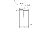
【課題】配線・配管材を収容保護する、直状保護カバーと付属保護カバーとをまとめて保持することができる、配線・配管材用の保護カバーの保持具を提供する。【解決手段】保持具5は、直状保護カバー3と付属保護カバー4とを、保持するものであって、それら保護カバー3、4の境界部分に配置される保持具本体5aと、その保持具本体5aから延びて配設面1に固定される固定部5bとを備える。保持具本体5aは、一側に、直状保護カバー3に跨がる第1本体部5xを有し、他側に、付属保護カバー4に跨がる第2本体部5yを有する。第1本体部5xには、直状保護カバー3の外周面に当接して配置されまたは隙間なく配置されて、その直状保護カバー3を支持する、第1支持部5cが設けられる。そして、第2本体部5yには、付属保護カバー4の外周面に当接して配置されまたは隙間なく配置されて、その付属保護カバー4を支持する、第2支持部5dが設けられる。【選択図】 図1Provided is a holder for a protective cover for wiring / piping material, which can accommodate and protect a straight protective cover and an attached protective cover for accommodating and protecting wiring / piping material. A holder 5 holds a straight protective cover 3 and an attached protective cover 4, and a holder body 5a disposed at a boundary portion between the protective covers 3 and 4 and the holding thereof. A fixing portion 5b extending from the tool body 5a and fixed to the arrangement surface 1. The holder main body 5a has a first main body portion 5x straddling the straight protective cover 3 on one side and a second main body portion 5y straddling the attached protective cover 4 on the other side. The first main body portion 5x is provided with a first support portion 5c that is disposed in contact with the outer peripheral surface of the straight protective cover 3 or is disposed without a gap and supports the straight protective cover 3. The second main body portion 5y is provided with a second support portion 5d that is disposed in contact with the outer peripheral surface of the attached protective cover 4 or arranged without a gap and supports the attached protective cover 4. [Selection] Figure 1
Description
この発明は、配線・配管材用の保護カバーの保持具、および配線・配管材用の保護カバーの保持装置であって、特に、直状保護カバーと付属保護カバーに係わる、保持具および保持装置に関するものである。 The present invention relates to a holder for a protective cover for wiring / piping material and a holding device for the protective cover for wiring / piping material, and in particular, to the direct protective cover and the attached protective cover. It is about.
従来、配線・配管材の保護カバーは、必要に応じて、直状保護カバーと、例えば分岐部分を形成する付属保護カバーとからなり、それら直状保護カバーと付属保護カバーとで配線・配管材の配線・配管経路を形成していた(例えば、特許文献1参照)。 Conventionally, a protective cover for wiring / piping material consists of a straight protective cover and an attached protective cover that forms, for example, a branch portion as necessary. Wiring / piping paths were formed (for example, see Patent Document 1).
そして、直状保護カバーは、基台と蓋体とからなっており、その直状保護カバーを保持したり基台への蓋体の組み付けを確実にしたりするために、保持具が用いられることがあった(例えば、特許文献2参照)。図17に示すように、この保持具24は、基台23aと蓋体23bとからなって配線・配管材22を収容保護する直状保護カバー23に対し、跨がるようにして、配設面21に取り付けられるものであって、直状保護カバー23に跨がってその直状保護カバー23を支持する支持部24aと、その支持部24aの両側に設けられて配設面21に固定される固定部24bとから構成されていた。
The straight protective cover is composed of a base and a lid, and a holder is used to hold the straight protective cover or to ensure that the lid is assembled to the base. (For example, refer to Patent Document 2). As shown in FIG. 17, the
しかし、前記従来の保持具24は、直状保護カバー23を保持することはできるものの、その直状保護カバー23と付属保護カバーとをまとめて保持することはできず、その使い勝手がよくなかった。
However, although the
この発明は、上記した従来の欠点を解決するためになされたものであり、その目的とするところは、直状保護カバーと付属保護カバーとをまとめて保持することができる、配線・配管材用の保護カバーの保持具、および配線・配管材用の保護カバーの保持装置を提供することにある。 The present invention has been made to solve the above-mentioned conventional drawbacks, and the object of the present invention is for wiring and piping materials that can hold a straight protective cover and an attached protective cover together. It is an object of the present invention to provide a protective cover holder and a protective cover holding device for wiring and piping materials.
この発明に係る配線・配管材用の保護カバーの保持具、および配線・配管材用の保護カバーの保持装置は、前記目的を達成するために、次の構成からなる。すなわち、
請求項1に記載の発明に係る配線・配管材用の保護カバーの保持具は、配設面に配設されて配線・配管材を収容保護する直状保護カバーと、その直状保護カバーの一端側の外周面に端部が重なるようにして前記配設面に配設されて配線・配管材を収容保護する付属保護カバーとを、保持する、保持具である。この保持具は、前記直状保護カバーと前記付属保護カバーとの境界部分に配置される保持具本体と、その保持具本体から延びて前記配設面に固定される固定部とを備える。ここで、前記保持具本体は、一側に、前記直状保護カバーに跨がる第1本体部を有し、他側に、前記付属保護カバーに跨がる第2本体部を有する。そして、前記第1本体部には、前記直状保護カバーの外周面に当接して配置されまたは隙間なく配置されて、その直状保護カバーを支持する、第1支持部が設けられ、前記第2本体部には、前記付属保護カバーの外周面に当接して配置されまたは隙間なく配置されて、その付属保護カバーを支持する、第2支持部が設けられる。
In order to achieve the above object, the holder for the protective cover for the wiring / piping material and the holding device for the protective cover for the wiring / piping material according to the present invention have the following configurations. That is,
According to the first aspect of the present invention, there is provided a holder for a protective cover for wiring / piping material, comprising a straight protective cover disposed on the installation surface for accommodating and protecting the wiring / piping material; It is a holder that holds an attached protective cover that is disposed on the arrangement surface so as to overlap an outer peripheral surface on one end side and accommodates and protects wiring and piping materials. The holder includes a holder main body disposed at a boundary portion between the straight protective cover and the attached protective cover, and a fixing portion that extends from the holder main body and is fixed to the arrangement surface. Here, the holder main body has a first main body portion straddling the straight protective cover on one side and a second main body portion straddling the attached protective cover on the other side. The first main body is provided with a first support that is disposed in contact with the outer peripheral surface of the straight protective cover or is disposed without a gap and supports the straight protective cover. The second main body portion is provided with a second support portion that is disposed in contact with the outer peripheral surface of the attached protective cover or arranged without a gap and supports the attached protective cover.
この保持具によると、保持具本体が、直状保護カバーと付属保護カバーとの境界部分に配置される。この保持具本体は、一側の、直状保護カバーに跨がる第1本体部に設けられた第1支持部が、直状保護カバーの外周面に当接または隙間なく配置されて、その直状保護カバーを支持し、他側の、付属保護カバーに跨がる第2本体部に設けられた第2支持部が、付属保護カバーの外周面に当接または隙間なく配置されて、その付属保護カバーを支持する。そして、保持具本体から延びる固定部が配設面に固定される。こうして、直状保護カバーと付属保護カバーとは、第1支持部と第2支持部とで個々に支持され、この保持具によりまとめて保持される。 According to this holder, the holder body is arranged at the boundary portion between the straight protective cover and the attached protective cover. In this holder main body, the first support portion provided on the first main body portion on one side straddling the straight protective cover is disposed without contact or gap on the outer peripheral surface of the straight protective cover, The second support portion provided on the second body portion supporting the straight protective cover and straddling the attached protective cover on the other side is disposed on the outer peripheral surface of the attached protective cover without any contact or gap. Support the attached protective cover. And the fixing | fixed part extended from a holder main body is fixed to an arrangement | positioning surface. Thus, the straight protective cover and the attached protective cover are individually supported by the first support portion and the second support portion, and are held together by this holder.
また、請求項2に記載の発明に係る配線・配管材用の保護カバーの保持具は、請求項1に記載の保持具において、前記固定部は、前記直状保護カバーと前記付属保護カバーとの配設方向に直交する両側に設けられる。こうして、固定部を両側に設けることで、保持具本体が安定し、直状保護カバーおよび付属保護カバーをしっかりと保持することができる。
Moreover, the holder of the protective cover for wiring / piping materials according to the invention described in
また、請求項3に記載の発明に係る配線・配管材用の保護カバーの保持装置は、請求項1または2に記載の保持具を用いた保持装置である。この保持装置は、保護カバー用スペーサーを介して前記配設面に配設される、前記直状保護カバーおよび前記付属保護カバーに対応すべく、前記保持具の固定部と前記配設面との間に介在して前記保持具を嵩上げする保持具用スペーサーを備える。こうして、保持具に対し、保持具用スペーサーを設けることで、直状保護カバーおよび付属保護カバーが、保護カバー用スペーサーを介して配設面に配設された場合にも、対応することができる。 A protective cover holding device for a wiring / piping material according to a third aspect of the invention is a holding device using the holder according to the first or second aspect. The holding device includes a fixing portion of the holding tool and the mounting surface, which are disposed on the mounting surface via a protective cover spacer, so as to correspond to the straight protective cover and the attached protective cover. There is provided a spacer for the holder that is interposed between the spacers and raises the holder. Thus, by providing the holder spacer for the holder, it is possible to cope with the case where the straight protective cover and the attached protective cover are arranged on the arrangement surface via the protective cover spacer. .
この発明に係る配線・配管材用の保護カバーの保持具、および配線・配管材用の保護カバーの保持装置によれば、保持具本体における第1支持部と第2支持部とで、直状保護カバーと付属保護カバーとを個々に支持し、かつ、固定部が配設面に固定されることで、両保護カバーをまとめて保持することができる。 According to the holder for the protective cover for wiring / piping material and the holding device for the protective cover for wiring / piping material according to the present invention, the first support portion and the second support portion in the holder main body Since the protective cover and the attached protective cover are individually supported and the fixing portion is fixed to the arrangement surface, both the protective covers can be held together.
以下、この発明に係る配線・配管材用の保護カバーの保持具、および配線・配管材用の保護カバーの保持装置を実施するための形態を図面に基づいて説明する。 EMBODIMENT OF THE INVENTION Hereinafter, the form for implementing the holding | maintenance apparatus of the protective cover for wiring and piping materials which concerns on this invention, and the protective cover for wiring and piping materials is demonstrated based on drawing.
図1〜図13は、本発明の一実施の形態を示す。図中符号1は、壁面、床面、天井面等からなる配設面を示す。2は、配線・配管材(配線材または配管材)を示す。3は、配線・配管材2用の直状保護カバーを示す。4は、配線・配管材2用の付属保護カバーを示す。5は、保護カバー(直状保護カバー3および付属保護カバー4)の保持具を示す。6は、保護カバー3、4の保持装置を示す。
1 to 13 show an embodiment of the present invention.
直状保護カバー3と付属保護カバー4は、配設面1に配設されて配線・配管材2を収容保護するものである。そして、付属保護カバー4は、直状保護カバー3の一端側の外周面に端部4aが重なるようにして配設面1に配設されて、これら直状保護カバー3と付属保護カバー4とは連なることとなる。そこで、保持具5は、これら直状保護カバー3と付属保護カバー4とを、保持するものであって、直状保護カバー3と付属保護カバー4との境界部分に配置される保持具本体5aと、その保持具本体5aから延びて配設面1に固定される固定部5bとを備える。ここで、保持具本体5aは、一側に、直状保護カバー3に跨がる第1本体部5xを有し、他側に、付属保護カバー4に跨がる第2本体部5yを有する。そして、第1本体部5xには、直状保護カバー3の外周面に当接して配置されまたは隙間なく配置されて、その直状保護カバー3を支持する、第1支持部5cが設けられ、第2本体部5yには、付属保護カバー4の外周面に当接して配置されまたは隙間なく配置されて、その付属保護カバー4を支持する、第2支持部5dが設けられる。
The straight
また、保持具本体5aは、その裏面側であって第1本体部5xと第2本体部5yとの境界位置に、付属保護カバー4の前記端部4aにおける端面4bに対向する対向面5eを有する。
The
保持装置6は、前記保持具5を用いた保持装置であって、保護カバー用スペーサー7を介して配設面1に配設される、直状保護カバー3および付属保護カバー4に対応すべく、保持具5の固定部5bと配設面1との間に介在して保持具5を嵩上げする保持具用スペーサー8を備える。
The holding
具体的には、配線・配管材2は、配管材からなり、給水湯管等の通水管とかエアコン用の冷媒管とかの管201であったり、その管201が接続される継手202であったりする。
Specifically, the wiring /
そして、直状保護カバー3は、真直ぐ延びて、配線・配管材2(詳しくは、管201)を収容保護する保護カバーであって、必要に応じて適宜長さに切断されて使用される。つまり、この直状保護カバー3は、その長手方向に直交する各断面形状が一定となっている。この直状保護カバー3は、図2および図3に示すように、配設面1側に位置する基台3aと、その基台3aに被る蓋体3bとを備える。基台3aは、配設面1と対向する基部3cと、その基部3cから延設されて、配線・配管材2を支持する配線・配管材支持部3dとを有している。蓋体3bは、断面略逆U字状に形成されて、基台3aに組み付けられる。ここで、蓋体3bには、内側に突設された被掛止め部3eが設けられ、この被掛止め部3eが、基台3aに設けられた凹状の掛止め部3fに掛かることで、蓋体3bは、基台3aに対し、弾性的に組み付けられる。なお、図中符号3gは、断熱材を示し、この断熱材3gは、蓋体3bの内面を覆うように設けられる。また、図示を省略するが、直状保護カバー3(詳しくは、基台3a)および後述する直状保護カバー用スペーサー701は、ビスとか釘等の固着具により、配設面1に固定される。
The straight
付属保護カバー4は、配線・配管材2(詳しくは、前記管201に続く継手202)を収容保護する保護カバーである。図示実施の形態においては、付属保護カバー4は、配線・配管材2の端側を収容保護する。この付属保護カバー4は、図3に示すように、配設面1側に位置する基台4cと、その基台4cに被る蓋体4dとを備える。基台4cは、その前面(配設面1とは反対側の面)に、継手202を部分的に収容する凹部4eを有している。そこで、継手202は、一部が凹部4eに収容された状態で、ビス9により、基台4cに固定される。蓋体4dは、後方(下方)に開口する箱型形状をした蓋体本体4eと、その蓋体本体4eから延設された断面略逆U字状の延設部4fとを備える。そして、この延設部4fの先端側が、付属保護カバー4の前記端部4aとなって、直状保護カバー3の一端側の外周面に重なることとなる。つまり、この端部4a(延設部4f)は、その内径(つまり、その開口幅および開口高さ)が、直状保護カバー3の外径(つまり、その幅および高さ)よりも大となるように形成されている。また、蓋体本体4eの前面(配設面1とは反対側の面)には、孔4gがあけられており、この孔4gを通って、水栓(図示せず)が、継手202の接続口2aに接続される。なお、図示を省略するが、この付属保護カバー4においても、直状保護カバー3と同様に、蓋体4dは、基台4cに対し、弾性的に組み付けられる。また、図示を省略するが、付属保護カバー4(詳しくは、基台4c)および後述する付属保護カバー用スペーサー702は、ビスとか釘等の固着具により、配設面1に固定される。
The attached
保持具5は、その保持具本体5a(第1本体部5xおよび第2本体部5y)が、帯状であって略逆U字状に延びて形成されている。そして、この保持具本体5aにおける第1本体部5xと第2本体部5yとは、相対的に第2本体部5yが、その内径が大となるように(つまり、その開口幅および開口高さが大となるように)段違いに形成され、その段差部分に、前述した対向面5eを有する。もっとも、図示実施の形態においては、第1本体部5xと第2本体部5yとは、相対的に第2本体部5yが、その内径のみならず外径においても大となるように段違いに形成されている。
The
そして、図示実施の形態においては、第1本体部5x自身が、第1支持部5cとなって、直状保護カバー3の外周面に当接して配置されまたは隙間なく配置され、同様にして、第2本体部5y自身が、第2支持部5dとなって、付属保護カバー4の外周面に当接して配置されまたは隙間なく配置される。すなわち、第1支持部5cと第2支持部5dとは、略逆U字状に形成され、相対的に第2支持部5dが、その内径が大となるように(つまり、その開口幅および開口高さが大となるように)形成される。
In the illustrated embodiment, the first
また、この保持具5において、固定部5bは、直状保護カバー3と付属保護カバー4との配設方向に直交する両側に設けられる。詳細には、固定部5bは、保持具本体5aの両端に設けられ、側方に板状に延びて、略方形形状に形成されている。この固定部5bには、固定部5b、ひいては保持具5を、配設面1に固定するためのビスとか釘等の固着具10が通る取付孔5fが貫通するようにあけられている。また、固定部5bは、保持具用スペーサー8に設けられた後述する嵌合部8dが嵌合する被嵌合部5gを有していてる。図示実施の形態においては、被嵌合部5gは、穴からなり、固定部5bの下面5h側にあけられている。
Further, in the
保護カバー用スペーサー7は、直状保護カバー3と配設面1との間に介在する直状保護カバー用スペーサー701と、付属保護カバー4と配設面1との間に介在する付属保護カバー用スペーサー702とからなる。そして、直状保護カバー用スペーサー701は、直状保護カバー3(詳しくは、基台3a)がちょうど載る大きさを有し、同様に、付属保護カバー用スペーサー702は、付属保護カバー4(詳しくは、基台4c)がちょうど載る大きさを有している。
The
保持具用スペーサー8は、保持具5のそれぞれの固定部5bと配設面1との間に個別に介在する。この保持具用スペーサー8は、盤状に形成され、かつ、上面8aが(詳しくは、下面8bを含めて)、保持具5における固定部5bの下面5hと略同一の大きさに形成されて、その上面8aが、固定部5bの下面5hに一致するように合わせられる。すなわち、図示実施の形態においては、保持具用スペーサー8は、固定部5bの略方形形状に合わせた、略方形形状をしている。そして、保持具用スペーサー8は、固定部5bの取付孔5fと連通可能な、取付孔8cが、貫通するようにあけられている。そこで、固着具10が、固定部5bの取付孔5fおよびこの取付孔8cを通って配設面1にねじ込まれたり打ち込まれたりする。
The
この保持具用スペーサー8は、嵌合部8dを有する。図示実施の形態においては、嵌合部8dは、突起からなり、保持具用スペーサー8の上面8a側に設けられる。そして、保持具5と保持具用スペーサー8とは、保持具5における被嵌合部5gにこの嵌合部8dが嵌合して組み付けられる(図1参照)。
The
また、保持具用スペーサー8は、必要に応じて、図13に示すように、高さ方向に積み重ねられて配置される。そこで、保持具用スペーサー8は、嵌合部8eと被嵌合部8fとを有している。図示実施の形態においては、嵌合部8eは、突起からなり、保持具用スペーサー8の上面8a側に設けられ、被嵌合部8fは、穴からなり、保持具用スペーサー8の下面8b側にあけられる。そして、一の保持具用スペーサー8の嵌合部8eが、他の保持具用スペーサー8の被嵌合部8fに嵌合して、複数の保持具用スペーサー8、8どうしが積み重ねられて組み付けられる。なお、図示実施の形態においては、保持具5と保持具用スペーサー8との組み付けに用いられる嵌合部8dと、保持具用スペーサー8、8どうしの組み付けに用いられる嵌合部8eとは、同一であるが(つまり、これらを兼ねた一つの嵌合部であるが)、これらを別々に形成してもよい。
Moreover, as shown in FIG. 13, the
また、保持具用スペーサー8は、保護カバー用スペーサー7の側面に当接する、当接部8gを有する。この当接部8gは、内側(つまり、保護カバー用スペーサー7側)を向く平面からなり、保護カバー用スペーサー7の平面からなる側面に安定して当接する。また、保持具用スペーサー8には、下面8bに、窪み8hが形成され、この窪み8hは、周面(図示実施の形態においては、当接部8g側の面)に開口するように設けられている。
The
次に、以上の構成からなる保持具5および保持装置6の作用効果について説明する。この保持具5によると、保持具本体5aが、直状保護カバー3と付属保護カバー4との境界部分に配置される。この保持具本体5aは、一側の、直状保護カバー3に跨がる第1本体部5xに設けられた第1支持部5cが、直状保護カバー3の外周面に当接または隙間なく配置されて、その直状保護カバー3を支持し、他側の、付属保護カバー4に跨がる第2本体部5yに設けられた第2支持部5dが、付属保護カバー4の外周面に当接または隙間なく配置されて、その付属保護カバー4を支持する。そして、保持具本体5aから延びる固定部5bが配設面1に固定される。こうして、直状保護カバー3と付属保護カバー4とは、第1支持部5cと第2支持部5dとで個々に支持され、保持具5によりまとめて保持される。すなわち、保持具本体5aにおける第1支持部5cと第2支持部5dとで、直状保護カバー3と付属保護カバー4とを個々に支持し、かつ、固定部5bが配設面1に固定されることで、両保護カバー(直状保護カバー3と付属保護カバー4と)をまとめて保持することができる。さらに、保持具本体5aに設けられた対向面5eが、付属保護カバー4の端面4bに対向するため、この付属保護カバー4の、直状保護カバー3側への位置ずれを防ぐことができる。
Next, the effect of the
また、固定部5bを、直状保護カバー3と付属保護カバー4との配設方向に直交する両側に設けることで、両固定部5b、5bが配設面1に固定されて保持具本体5aが安定し、直状保護カバー3および付属保護カバー4をしっかりと保持することができる。
Further, by providing the fixing
また、保持装置6にあっては、前記作用効果に加えて、保持具5に対し、保持具用スペーサー8を設けることで、直状保護カバー3および付属保護カバー4が、保護カバー用スペーサー7を介して配設面1に配設された場合にも、対応することができ、使い勝手がよい。
In addition, in addition to the above-described effects, the holding
なお、本発明は、上述した実施の形態に限定されるわけではなく、その他種々の変更が可能である。例えば、保護カバー3、4は、基台3a、4cと蓋体3b、4dとを備えるものでなくとも、例えば、パイプとかダクト(特に、下面がフラットなパイプとかダクト)からなっていてもよく、また、下方が開口するものであってもよい。
In addition, this invention is not necessarily limited to embodiment mentioned above, A various other change is possible. For example, the
また、付属保護カバー4は、配線・配管材2における配線・配管経路の端部を収容保護するものでなくとも、その配線・配管経路の曲がり部分、分岐部分、延長部分等の中間部を収容保護するものであってもよい。図14〜図15は、分岐部分用の付属保護カバー4を用いた例を示し、付属保護カバー4および付属保護カバー用スペーサー702は、T字状に形成されている。ここで、図14は、斜視図、図15は、分解斜視図である。
Further, the attached
また、直状保護カバー3および付属保護カバー4の配設にあたって、保護カバー用スペーサ7(直状保護カバー用スペーサー701および付属保護カバー用スペーサー702)とか保持具用スペーサー8を用いることなく、図16に示すように、保護カバー3、4や保持具5が、直接配設面1に取り付けられてもよい。
Further, when the direct
また、この図16に示すように、保持具5における第1本体部5x自身が第1支持部5cとなるのではなく、例えば、第1本体部5xと第2本体部5yとが段差なく繋がり、第1支持部5cが、第1本体部5xから内側に突出して形成された突出片からなっていてもよい。ここで、この突出片からなる第1支持部5cは、第1本体部5xにおける、直状保護カバー3に跨がる方向の全周に設けられても、一部に設けられてもよい。また、図示を省略するが、第1支持部5cと同様にして、第2支持部5dは、第2本体部5yから内側に突出して形成された突出片からなっていてもよい。そして、この突出片からなる第2支持部5dは、第2本体部5yにおける、付属保護カバー4に跨がる方向の全周に設けられても、一部に設けられてもよい。
Further, as shown in FIG. 16, the first
また、保持具5において、固定部5bは、直状保護カバー3と付属保護カバー4との配設方向に直交する両側に設けられなくとも、一側にのみ設けられるものであってもよい。
Further, in the
1 配設面
2 配線・配管材
3 直状保護カバー
4 付属保護カバー
4a 端部
5 保持具
5a 保持具本体
5b 固定部
5c 第1支持部
5d 第2支持部
5x 第1本体部
5y 第2本体部
6 保持装置
7 保護カバー用スペーサー
8 保持具用スペーサー
DESCRIPTION OF
Claims (3)
前記直状保護カバーと前記付属保護カバーとの境界部分に配置される保持具本体と、その保持具本体から延びて前記配設面に固定される固定部とを備え、
前記保持具本体は、一側に、前記直状保護カバーに跨がる第1本体部を有し、他側に、前記付属保護カバーに跨がる第2本体部を有し、かつ、
前記第1本体部には、前記直状保護カバーの外周面に当接して配置されまたは隙間なく配置されて、その直状保護カバーを支持する、第1支持部が設けられ、前記第2本体部には、前記付属保護カバーの外周面に当接して配置されまたは隙間なく配置されて、その付属保護カバーを支持する、第2支持部が設けられる、配線・配管材用の保護カバーの保持具。 A straight protective cover disposed on the mounting surface to accommodate and protect the wiring / piping material, and disposed on the mounting surface such that an end thereof overlaps an outer peripheral surface of one end side of the straight protective cover. A holding tool that holds an attached protective cover that accommodates and protects wiring and piping materials,
A holder main body disposed at a boundary portion between the straight protective cover and the attached protective cover, and a fixing portion extending from the holder main body and fixed to the arrangement surface,
The holder main body has a first main body portion straddling the straight protective cover on one side, a second main body portion straddling the attached protective cover on the other side, and
The first main body portion is provided with a first support portion that is disposed in contact with the outer peripheral surface of the straight protective cover or is disposed without a gap and supports the straight protective cover, and the second main body. The portion is provided in contact with the outer peripheral surface of the attached protective cover, or is disposed without a gap, and is provided with a second support portion that supports the attached protective cover, holding the protective cover for wiring and piping materials Ingredients.
保護カバー用スペーサーを介して前記配設面に配設される、前記直状保護カバーおよび前記付属保護カバーに対応すべく、前記保持具の固定部と前記配設面との間に介在して前記保持具を嵩上げする保持具用スペーサーを備える、配線・配管材用の保護カバーの保持装置。 A holding device using the holder according to claim 1 or 2,
In order to correspond to the straight protective cover and the attached protective cover, which are arranged on the arrangement surface via a protective cover spacer, are interposed between the fixing portion of the holder and the arrangement surface. A holding device for a protective cover for a wiring / piping material, comprising a spacer for a holding tool for raising the holding tool.
Priority Applications (1)
| Application Number | Priority Date | Filing Date | Title |
|---|---|---|---|
| JP2013093059A JP6133670B2 (en) | 2013-04-25 | 2013-04-25 | Protective cover holder for wiring and piping materials, and protective cover holding device for wiring and piping materials |
Applications Claiming Priority (1)
| Application Number | Priority Date | Filing Date | Title |
|---|---|---|---|
| JP2013093059A JP6133670B2 (en) | 2013-04-25 | 2013-04-25 | Protective cover holder for wiring and piping materials, and protective cover holding device for wiring and piping materials |
Publications (2)
| Publication Number | Publication Date |
|---|---|
| JP2014214821A true JP2014214821A (en) | 2014-11-17 |
| JP6133670B2 JP6133670B2 (en) | 2017-05-24 |
Family
ID=51940789
Family Applications (1)
| Application Number | Title | Priority Date | Filing Date |
|---|---|---|---|
| JP2013093059A Active JP6133670B2 (en) | 2013-04-25 | 2013-04-25 | Protective cover holder for wiring and piping materials, and protective cover holding device for wiring and piping materials |
Country Status (1)
| Country | Link |
|---|---|
| JP (1) | JP6133670B2 (en) |
Cited By (2)
| Publication number | Priority date | Publication date | Assignee | Title |
|---|---|---|---|---|
| JP2017096499A (en) * | 2015-11-13 | 2017-06-01 | 三愛化成商事株式会社 | Cover tube for cable |
| WO2020162367A1 (en) * | 2019-02-05 | 2020-08-13 | Necプラットフォームズ株式会社 | Pipe protection device and cooling device |
Citations (3)
| Publication number | Priority date | Publication date | Assignee | Title |
|---|---|---|---|---|
| JPS5659375U (en) * | 1979-10-12 | 1981-05-21 | ||
| JP2002213681A (en) * | 2001-01-18 | 2002-07-31 | Inaba Denki Sangyo Co Ltd | Connection for long body cover |
| JP2012149679A (en) * | 2011-01-18 | 2012-08-09 | Inaba Denki Sangyo Co Ltd | Long body cover fitting and long body cover device |
-
2013
- 2013-04-25 JP JP2013093059A patent/JP6133670B2/en active Active
Patent Citations (3)
| Publication number | Priority date | Publication date | Assignee | Title |
|---|---|---|---|---|
| JPS5659375U (en) * | 1979-10-12 | 1981-05-21 | ||
| JP2002213681A (en) * | 2001-01-18 | 2002-07-31 | Inaba Denki Sangyo Co Ltd | Connection for long body cover |
| JP2012149679A (en) * | 2011-01-18 | 2012-08-09 | Inaba Denki Sangyo Co Ltd | Long body cover fitting and long body cover device |
Cited By (4)
| Publication number | Priority date | Publication date | Assignee | Title |
|---|---|---|---|---|
| JP2017096499A (en) * | 2015-11-13 | 2017-06-01 | 三愛化成商事株式会社 | Cover tube for cable |
| WO2020162367A1 (en) * | 2019-02-05 | 2020-08-13 | Necプラットフォームズ株式会社 | Pipe protection device and cooling device |
| JP2020126480A (en) * | 2019-02-05 | 2020-08-20 | Necプラットフォームズ株式会社 | Pipe protector and cooling system |
| US12156373B2 (en) | 2019-02-05 | 2024-11-26 | Nec Platforms, Ltd. | Pipe protection device and cooling device |
Also Published As
| Publication number | Publication date |
|---|---|
| JP6133670B2 (en) | 2017-05-24 |
Similar Documents
| Publication | Publication Date | Title |
|---|---|---|
| US9203222B2 (en) | While in use weatherproof cover for an electrical box | |
| US20160230969A1 (en) | Recessed light fixture | |
| JP5095372B2 (en) | Wiring / Piping material protection cover | |
| JP6133670B2 (en) | Protective cover holder for wiring and piping materials, and protective cover holding device for wiring and piping materials | |
| JP5616181B2 (en) | Fixture | |
| JP4725523B2 (en) | Temperature sensor fixing device and air conditioner equipped with the same | |
| JP2009104948A (en) | Direct mounting appliance | |
| JP6118626B2 (en) | Protective cover device for wiring / piping material, arrangement structure of protective cover for wiring / piping material, and spacer for holder | |
| JP5291076B2 (en) | Decorative cover and decorative cover device for wall penetration | |
| JP6138637B2 (en) | Wiring box, sound insulation material, and sound insulation method for wiring box installation location on hollow wall | |
| JP2011133149A (en) | Heat pump type heat source device and heat pump water heater using the same | |
| JP5890632B2 (en) | Wiring duct and wiring duct installation method | |
| JP2008014525A (en) | Air sensor temperature sensor fixing device | |
| JP4174807B2 (en) | Electrical entry cover for cable duct | |
| JP4616655B2 (en) | Straight protective cover connecting cover | |
| JP2017135814A (en) | Protector for wiring harness | |
| JP5490675B2 (en) | Hot water storage water heater | |
| JP5378069B2 (en) | Wiring duct | |
| US20120188718A1 (en) | Assembly of an Electronic Device Casing, A Heat-Dissipating Module and a Waterproofing Module, and the Waterproofing Module | |
| JP4936097B2 (en) | Speed cover | |
| JP6180947B2 (en) | Wiring / Piping material protection cover | |
| JP6224962B2 (en) | Thermal insulation panel | |
| JP2021099941A (en) | Lighting fixture | |
| JP2006292011A (en) | Protective material for wiring and piping materials | |
| JP2009204170A (en) | Temperature sensor fixing device for air conditioner |
Legal Events
| Date | Code | Title | Description |
|---|---|---|---|
| A621 | Written request for application examination |
Free format text: JAPANESE INTERMEDIATE CODE: A621 Effective date: 20151127 |
|
| A977 | Report on retrieval |
Free format text: JAPANESE INTERMEDIATE CODE: A971007 Effective date: 20161020 |
|
| A131 | Notification of reasons for refusal |
Free format text: JAPANESE INTERMEDIATE CODE: A131 Effective date: 20161025 |
|
| A521 | Request for written amendment filed |
Free format text: JAPANESE INTERMEDIATE CODE: A523 Effective date: 20161216 |
|
| TRDD | Decision of grant or rejection written | ||
| A01 | Written decision to grant a patent or to grant a registration (utility model) |
Free format text: JAPANESE INTERMEDIATE CODE: A01 Effective date: 20170328 |
|
| A61 | First payment of annual fees (during grant procedure) |
Free format text: JAPANESE INTERMEDIATE CODE: A61 Effective date: 20170420 |
|
| R150 | Certificate of patent or registration of utility model |
Ref document number: 6133670 Country of ref document: JP Free format text: JAPANESE INTERMEDIATE CODE: R150 |
|
| R250 | Receipt of annual fees |
Free format text: JAPANESE INTERMEDIATE CODE: R250 |
|
| R250 | Receipt of annual fees |
Free format text: JAPANESE INTERMEDIATE CODE: R250 |
|
| R250 | Receipt of annual fees |
Free format text: JAPANESE INTERMEDIATE CODE: R250 |
|
| R250 | Receipt of annual fees |
Free format text: JAPANESE INTERMEDIATE CODE: R250 |
|
| R250 | Receipt of annual fees |
Free format text: JAPANESE INTERMEDIATE CODE: R250 |
|
| R250 | Receipt of annual fees |
Free format text: JAPANESE INTERMEDIATE CODE: R250 |