JP2014204361A - On-vehicle monitoring system and on-vehicle camera adapter - Google Patents
On-vehicle monitoring system and on-vehicle camera adapter Download PDFInfo
- Publication number
- JP2014204361A JP2014204361A JP2013080423A JP2013080423A JP2014204361A JP 2014204361 A JP2014204361 A JP 2014204361A JP 2013080423 A JP2013080423 A JP 2013080423A JP 2013080423 A JP2013080423 A JP 2013080423A JP 2014204361 A JP2014204361 A JP 2014204361A
- Authority
- JP
- Japan
- Prior art keywords
- image
- vehicle
- vehicle camera
- event
- switching
- Prior art date
- Legal status (The legal status is an assumption and is not a legal conclusion. Google has not performed a legal analysis and makes no representation as to the accuracy of the status listed.)
- Pending
Links
- 238000012544 monitoring process Methods 0.000 title claims abstract description 89
- 238000003702 image correction Methods 0.000 claims abstract description 36
- 238000001514 detection method Methods 0.000 claims description 40
- 230000004913 activation Effects 0.000 claims description 14
- 239000012141 concentrate Substances 0.000 abstract description 20
- 238000012806 monitoring device Methods 0.000 abstract 2
- 238000000034 method Methods 0.000 description 38
- 238000004891 communication Methods 0.000 description 14
- 238000010586 diagram Methods 0.000 description 11
- 238000012545 processing Methods 0.000 description 7
- 238000003384 imaging method Methods 0.000 description 6
- 238000005259 measurement Methods 0.000 description 6
- 238000006243 chemical reaction Methods 0.000 description 4
- 125000004122 cyclic group Chemical group 0.000 description 4
- 238000009966 trimming Methods 0.000 description 3
- 230000000994 depressogenic effect Effects 0.000 description 2
- 238000006073 displacement reaction Methods 0.000 description 2
- 238000004519 manufacturing process Methods 0.000 description 2
- 238000002360 preparation method Methods 0.000 description 2
- 230000002265 prevention Effects 0.000 description 2
- 230000004397 blinking Effects 0.000 description 1
- 238000012937 correction Methods 0.000 description 1
- 230000007423 decrease Effects 0.000 description 1
- 230000000694 effects Effects 0.000 description 1
- 238000005070 sampling Methods 0.000 description 1
- 230000007704 transition Effects 0.000 description 1
Images


Classifications
-
- H—ELECTRICITY
- H04—ELECTRIC COMMUNICATION TECHNIQUE
- H04N—PICTORIAL COMMUNICATION, e.g. TELEVISION
- H04N7/00—Television systems
- H04N7/18—Closed-circuit television [CCTV] systems, i.e. systems in which the video signal is not broadcast
- H04N7/183—Closed-circuit television [CCTV] systems, i.e. systems in which the video signal is not broadcast for receiving images from a single remote source
Landscapes
- Engineering & Computer Science (AREA)
- Multimedia (AREA)
- Signal Processing (AREA)
- Closed-Circuit Television Systems (AREA)
- Studio Devices (AREA)
- Mechanical Engineering (AREA)
- Traffic Control Systems (AREA)
- Fittings On The Vehicle Exterior For Carrying Loads, And Devices For Holding Or Mounting Articles (AREA)
Abstract
Description
本発明は、車載カメラで撮像した画像をモニタ装置でライブ表示する車載モニタリングシステムにおいて、画像を車載カメラからモニタ装置へ中継する車載カメラ用アダプターに関する。 The present invention relates to a vehicle-mounted camera adapter that relays an image from a vehicle-mounted camera to a monitor device in a vehicle-mounted monitoring system that displays an image captured by the vehicle-mounted camera live on a monitor device.
近年のデジタルカメラ類の一つに、撮像した画像を当該画像の用途にあわせて最適な画像へ補正するという画像補正手段を備えたデジタルカメラがある。
当該デジタルカメラは、撮像した一枚の元画像から、画像補正手段によってそれぞれアングルが異なる複数枚の画像を形成することができる。これにより、たとえば、広角レンズを用いた一枚の広角元画像から、周囲をトリミングして形成した標準画角の画像や、広角元画像の一部を切り出して歪みを補正し、拡大した部分拡大画像等を形成することができる。画像補正手段で形成される画像は、デジタルカメラの所定の操作にしたがって、その都度モニタ画面に表示される。すなわち、当該デジタルカメラは、アングルの異なる画像を切替可能な画角切替機能を有する。当該デジタルカメラを以下「画角切替機能付カメラ」という。当該画角切替機能付カメラについては、特開2010−154572号公報等に開示されている。
As one of recent digital cameras, there is a digital camera provided with an image correction unit that corrects a captured image to an optimum image according to the use of the image.
The digital camera can form a plurality of images having different angles by the image correcting unit from one captured original image. As a result, for example, from a single wide-angle original image using a wide-angle lens, an image with a standard angle of view formed by trimming the periphery or a part of the wide-angle original image is cut out to correct distortion, and an enlarged partial enlargement An image or the like can be formed. The image formed by the image correction means is displayed on the monitor screen each time according to a predetermined operation of the digital camera. That is, the digital camera has an angle-of-view switching function capable of switching images having different angles. The digital camera is hereinafter referred to as “camera with angle-of-view switching function”. The camera with the angle of view switching function is disclosed in Japanese Patent Application Laid-Open No. 2010-154572.
当該画角切替機能付カメラは、カーナビゲーションシステムに代表される運転支援システムへバックカメラとして組み込まれている。バックカメラとは、主として車体後方を撮像するものをいう。当該バックカメラで撮像された車体後方の画像は、シフトをリバースに入れたとき、カーナビゲーションシステムのモニタ画面上で地図等が示されたナビゲーション画面と入れ替わって表示される。
画角切替機能付カメラをバックカメラとした場合には、駐停車の際にアングルが異なる複数の画像のうち、ドライバーが選択した一の画像をすることができる。
The camera with an angle of view switching function is incorporated as a back camera in a driving support system represented by a car navigation system. A back camera means what mainly image | photographs the vehicle body back. An image of the rear of the vehicle imaged by the back camera is displayed in place of a navigation screen showing a map or the like on the monitor screen of the car navigation system when the shift is reversed.
When a camera with an angle-of-view switching function is used as a back camera, one image selected by the driver among a plurality of images having different angles when parked or stopped can be displayed.
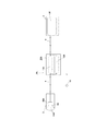
ここで、図12に示すように、バックカメラとして用いられる画角切替機能付カメラ1は、カーナビゲーションシステムのモニタ2と専用コネクタ3,3を備えた専用ケーブル4で接続されている。
専用ケーブル4は、画像信号ケーブル4aと、画角切替信号ケーブル4bとからなる。
画像信号ケーブル4aは、画角切替機能付カメラ1からモニタ2に向かって画像信号vが伝送するように形成されている。
画像信号vは、画角切替機能付カメラ1が発信するように形成されている。なお、画角切替機能付カメラ1は、シフトをリバースに入れたときに出力されるバック信号によって起動するように形成されている。
これにより、シフトをリバースに入れて車がバックし始めたとき、モニタ2で表示されていたナビゲーション画面は、画角切替機能付カメラ1からモニタ2へ送信された画像信号vに基づく車体後方の画像へ瞬時に切り替えられる。
Here, as shown in FIG. 12, a
The
The image signal cable 4 a is formed so that the image signal v is transmitted from the
The image signal v is formed so that the
As a result, when the shift is reversed and the vehicle starts to reverse, the navigation screen displayed on the
画角切替信号ケーブル4bは、画角切替機能付カメラ1の画角切替機能をモニタ2側から遠隔操作するための画角切替信号c1,c2が、モニタ2から画角切替機能付カメラ1に向かって伝送するように形成されている。
これにより、たとえば、ドライバーがモニタ2のスクリーン2a上に設けたタッチパネル2bを操作したとき、当該ドライバーは、画角切替機能付カメラ1の画角切替機能を遠隔操作することができる。
The angle-of-view
Thereby, for example, when the driver operates the
ここで、上記のような画像切替機能付カメラ1は対となる専用のモニタ2を使用することが推奨されている。そして上記の画像切替機能は特に専用品とセットでなければ、使用することはできない。これにより、たとえば、バックカメラが付いていない既存のカーナビゲーションシステムに対して、新たに画角切替機能付カメラをバックカメラとして組み込もうとする場合等においては、画像信号や画角切替信号をカメラとカーナビゲーションシステムとの間で送受信することができない。
そのため、せっかく画角切替機能付カメラを新たに導入したにもかかわらず、ユーザーは当該画角切替機能を十分に活用することができない。
Here, it is recommended that the
Therefore, even though a camera with a view angle switching function has been newly introduced, the user cannot fully utilize the view angle switching function.
また、上記のように、画角切替機能付カメラ1とモニタ2を専用コネクタ3,3を備えた専用ケーブル4で接続した従来のカーナビゲーションシステムは、画角切替操作をする際に安全を確保するため、車を一旦停止させなければならない。ここで、車庫入れ開始時に周囲の確認をし、車庫入れ最中には左右の間隔を確認し、最後に車体後端と車止めの位置を確認するといった車体の後方を異なったアングルで確認しつつ車をバックさせたい場合等には、当該後退運転操作中に、画角切替操作という割り込み操作を行うことになるので、ドライバーは運転操作に集中できず、却って運転操作がおろそかになるおそれがある。
In addition, as described above, the conventional car navigation system in which the
また、後退運転中、特に車庫入れ等の駐車運転操作や、狭い道路で進路を譲る場合には微速で後方へ特に注意を払いながら後退しなければならない場面がある。この場面において、モニタ装置に映し出される後方の画像が次々に切り替わったり、必要な画面がすぐに見られないようであっては、ドライバーは運転操作に集中することができない。 In addition, there are scenes where it is necessary to retreat while paying particular attention to the rear at a very low speed during reversing operation, especially when parking operation such as garage entry or when giving way on a narrow road. In this scene, the driver cannot concentrate on the driving operation if the rear images displayed on the monitor device are switched one after another or the necessary screen cannot be seen immediately.
したがって、本発明が解決しようとする課題は、後退運転時にドライバーが運転操作に集中することができるようにした車載モニタリングシステムにおける車載カメラ用アダプターを提供することである。 Therefore, the problem to be solved by the present invention is to provide an in-vehicle camera adapter in an in-vehicle monitoring system that allows a driver to concentrate on driving operation during reverse driving.
請求項1に記載の車載モニタリングシステムにおける車載カメラ用アダプターは、車両後方を中心に当該車両周辺を撮像する車載カメラ、撮像した映像又は静止画又はこれらに類する画像を表示するモニタ装置、及び前記車載カメラから出力される画像を前記モニタ装置へ中継する車載カメラ用アダプターを有する車載モニタリングシステムにおいて、
前記車載カメラに、
当該車載カメラで撮像した元画像を補正変換して複数枚の変換画像を形成する画像補正手段と、
当該変換画像のうち、選択した任意の前記変換画像を自動又は手動で切り替え可能な画像切替手段とを設け、
前記画像補正手段は、あたかも上方から俯瞰したかのような直下画像を形成する直下画像形成手段を有し、
前記車載カメラ用アダプターに、
前記変換画像を、前記車載カメラから前記モニタ装置へ中継する画像中継手段と、
前記画像切替手段に対して通常切替制御信号を出力して自動又は手動で前記変換画像の切り替えを制御する切替制御手段を設けて、
後退運転を開始した場合に前記変換画像を前記モニタ装置で表示するとき、
前記変換画像を、前記車載カメラから前記モニタ装置へ中継すると共に、
前記車載カメラが送信する前記変換画像の切り替えを自動で又は手動で制御するようにした車載モニタリングシステムにおける車載カメラ用アダプターであって、
当該車載カメラ用アダプターに、
一連の後退運転動作のうち、当該後退運転動作が最終段階に移行したか否かを判定するための車体の挙動を示す所定のイベントを検知する検知手段を設け、
当該検知手段は、前記イベントを検知したときにタイマ起動信号を出力するセンサと、
当該タイマ起動信号を受信した場合に前記イベントの実行時間を計測を開始して、当該イベントが所定の時間以上連続して実行されたとき、前記切替制御手段へトリガ信号を出力するイベントタイマとを有し、
当該トリガ信号を受信した前記切替制御手段は、前記モニタ装置で表示している前記変換画像を前記直下画像へ切り替えるための特定切替制御信号を前記画像切替手段に対して出力して、
後退運転中に前記イベントが所定時間以上続いたとき、
前記車載カメラ用アダプターが、前記変換画像のうち、前記直下画像を表示するように前記画像切替手段の制御をするようにしたことを特徴とする。
The in-vehicle camera adapter in the in-vehicle monitoring system according to
In the in-vehicle camera,
Image correction means for correcting and converting the original image captured by the in-vehicle camera to form a plurality of converted images;
Among the converted images, provided with an image switching means capable of automatically or manually switching any of the selected converted images,
The image correction unit includes a direct image forming unit that forms a direct image as if seen from above.
In the in-vehicle camera adapter,
Image relay means for relaying the converted image from the in-vehicle camera to the monitor device;
Providing a switching control means for controlling the switching of the converted image automatically or manually by outputting a normal switching control signal to the image switching means;
When displaying the converted image on the monitor device when starting reverse operation,
While relaying the converted image from the in-vehicle camera to the monitor device,
An in-vehicle camera adapter in an in-vehicle monitoring system that automatically or manually controls switching of the converted image transmitted by the in-vehicle camera,
In the in-vehicle camera adapter,
A detection means for detecting a predetermined event indicating the behavior of the vehicle body for determining whether or not the reverse driving operation has shifted to the final stage in the series of reverse driving operations,
The detection means includes a sensor that outputs a timer start signal when detecting the event;
An event timer that starts measuring the execution time of the event when the timer activation signal is received and outputs a trigger signal to the switching control means when the event is continuously executed for a predetermined time or longer. Have
The switching control means that has received the trigger signal outputs a specific switching control signal for switching the converted image displayed on the monitor device to the immediately below image to the image switching means,
When the event continues for a predetermined time or longer during reverse operation,
The on-vehicle camera adapter controls the image switching means so as to display the direct image among the converted images.
請求項2に記載の車載モニタリングシステムにおける車載カメラ用アダプターは、車両後方を中心に当該車両周辺を撮像する車載カメラ、撮像した映像又は静止画又はこれらに類する画像を表示するモニタ装置、及び前記車載カメラから出力される画像を前記モニタ装置へ中継する車載カメラ用アダプターを有する車載モニタリングシステムにおいて、
前記車載カメラ用アダプターに、
前記車載カメラで撮像した元画像を補正変換して複数枚の変換画像を形成する画像補正手段と、
前記変換画像のうち、選択した任意の前記変換画像を自動又は手動で切り替え可能な画像切替手段と、
前記車載カメラから入力された前記元画像に基づく前記変換画像を前記モニタ装置へ中継する画像中継手段と、
前記画像切替手段に対して通常切替制御信号を出力して自動又は手動で前記変換画像の切り替えを制御する切替制御手段とを設け、
前記画像補正手段は、あたかも上方から俯瞰したかのような直下画像を形成する直下画像形成手段を有し、
後退運転を開始した場合に前記変換画像を前記モニタ装置で表示するとき、
前記車載カメラから入力された前記元画像に基づく前記変換画像を、前記モニタ装置へ中継すると共に、
前記モニタ装置上に表示する前記変換画像の切り替えを自動で又は手動で制御するようにした車載モニタリングシステムにおける車載カメラ用アダプターであって、
当該車載カメラ用アダプターに、
一連の後退運転動作のうち、当該後退運転動作が最終段階に移行したか否かを判定するための車体の挙動を示す所定のイベントを検知する検知手段を設け、
当該検知手段は、前記イベントを検知したときにタイマ起動信号を出力するセンサと、
当該タイマ起動信号を受信した場合に前記イベントの実行時間を計測を開始して、当該イベントが所定の時間以上連続して実行されたとき、前記切替制御手段へトリガ信号を出力するイベントタイマとを有し、
当該トリガ信号を受信した前記切替制御手段は、前記モニタ装置で表示している前記変換画像を前記直下画像へ切り替えるための特定切替制御信号を前記画像切替手段に対して出力して、
後退運転中に前記イベントが所定時間以上続いたとき、
前記車載カメラ用アダプターが、前記変換画像のうち、前記直下画像を出力するようにしたことを特徴とする。
The in-vehicle camera adapter in the in-vehicle monitoring system according to
In the in-vehicle camera adapter,
Image correction means for correcting and converting the original image captured by the in-vehicle camera to form a plurality of converted images;
Among the converted images, image switching means capable of automatically or manually switching any selected converted image;
Image relay means for relaying the converted image based on the original image input from the in-vehicle camera to the monitor device;
A switching control means for controlling the switching of the converted image automatically or manually by outputting a normal switching control signal to the image switching means,
The image correction unit includes a direct image forming unit that forms a direct image as if seen from above.
When displaying the converted image on the monitor device when starting reverse operation,
While relaying the converted image based on the original image input from the in-vehicle camera to the monitor device,
An in-vehicle camera adapter in an in-vehicle monitoring system that automatically or manually controls switching of the converted image displayed on the monitor device,
In the in-vehicle camera adapter,
A detection means for detecting a predetermined event indicating the behavior of the vehicle body for determining whether or not the reverse driving operation has shifted to the final stage in the series of reverse driving operations,
The detection means includes a sensor that outputs a timer start signal when detecting the event;
An event timer that starts measuring the execution time of the event when the timer activation signal is received and outputs a trigger signal to the switching control means when the event is continuously executed for a predetermined time or longer. Have
The switching control means that has received the trigger signal outputs a specific switching control signal for switching the converted image displayed on the monitor device to the immediately below image to the image switching means,
When the event continues for a predetermined time or longer during reverse operation,
The on-vehicle camera adapter is configured to output the image directly below the converted image.
請求項3に記載の車載モニタリングシステムにおける車載カメラ用アダプターは、請求項1若しくは請求項2に記載の発明において、車両の後退する速度が所定の速度以下になったとき、前記イベントが発生するようにして、当該イベントを前記センサが検知するようにしたことを特徴とする。
The on-vehicle camera adapter in the in-vehicle monitoring system according to
請求項4に記載の車載モニタリングシステムにおける車載カメラ用アダプターは、請求項3に記載の発明において、前記センサが、車速を検知する速度センサであることを特徴とする。
The on-vehicle camera adapter in the in-vehicle monitoring system according to
請求項5に記載の車載モニタリングシステムにおける車載カメラ用アダプターは、請求項3に記載の発明において、前記センサが、ブレーキランプを点灯させる電流又は電圧による点灯信号を検知するようにしたことを特徴とする。
The on-vehicle camera adapter in the in-vehicle monitoring system according to
請求項6に記載の車載モニタリングシステムにおける車載カメラ用アダプターは、請求項3に記載の発明において、前記センサが、ブレーキペダルにかかる踏圧を検知する圧力センサであることを特徴とする。
The on-vehicle camera adapter in the in-vehicle monitoring system according to claim 6 is characterized in that, in the invention according to
請求項7に記載の車載モニタリングシステムにおける車載カメラ用アダプターは、請求項1若しくは請求項2に記載の発明において、ステアリングホイールの切れ角が所定の角度以下となったとき、前記イベントが発生する共に、当該イベントを検知する前記センサが、舵角センサであることを特徴とする。
The on-vehicle camera adapter in the in-vehicle monitoring system according to claim 7 is the invention according to
請求項8に記載の車載モニタリングシステムにおける車載カメラ用アダプターは、請求項1若しくは請求項2に記載の発明において、前記イベントが、車体後方に有る壁面若しくは柱又はこれらに類する障害物との距離が所定の距離以下となったときに、前記イベントが発生するようにして、
当該イベントを前記センサが検知するようにしたことを特徴とする。
The on-vehicle camera adapter in the in-vehicle monitoring system according to claim 8 is the invention according to
The event is detected by the sensor.
請求項9に記載の車載モニタリングシステムにおける車載カメラ用アダプターは、請求項8に記載の発明において、前記センサが、前記障害物に対してパルス波を照射し、当該パルス波を発射した瞬間から反射したパルス波を受信するまでの時間を計測して、前記障害物との距離を測定するレーダであることを特徴とする。 The in-vehicle camera adapter in the in-vehicle monitoring system according to claim 9 is the invention according to claim 8, wherein the sensor irradiates the obstacle with a pulse wave and reflects from the moment when the pulse wave is emitted. The radar is characterized in that it measures the time until the received pulse wave is received and measures the distance from the obstacle.
請求項10に記載の車載モニタリングシステムにおける車載カメラ用アダプターは、請求項9に記載の発明において、前記パルス波は、周波数が1GHz乃至300GHzのマイクロ波帯に属する電磁波であることを特徴とする。
The on-vehicle camera adapter in the in-vehicle monitoring system according to
請求項11に記載の車載モニタリングシステムにおける車載カメラ用アダプターは、請求項9に記載の発明において、前記パルス波は、周波数が20kHz以上の超音波帯に属する音波であることを特徴とする。
The on-vehicle camera adapter in the on-vehicle monitoring system according to
請求項12に記載の車載モニタリングシステムにおける車載カメラ用アダプターは、請求項8に記載の発明において、前記センサが、前記車載カメラで撮像した画像内に映り込んだ前記障害物を含む所定のポイントを少なくとも一つサンプリングし、当該ポイント付近のコントラストの変化に基づいて当該ポイントとの距離を測定するオートフォーカスセンサであることを特徴とする。
The on-vehicle camera adapter in the in-vehicle monitoring system according to
請求項1に記載の車載モニタリングシステムにおける車載カメラ用アダプターによれば、
車載カメラ用アダプターに、一連の後退運転動作のうち、当該後退運転動作が最終段階に移行したか否かを判定するための車体の挙動を示す所定のイベントを検知する検知手段を設けた。当該検知手段がイベントを検知したとき、所定時間経過してから切替制御手段を制御するようにした。これによって、後退運転中であって、かつ、イベントが所定時間以上続いたとき、車載カメラ用アダプターは、後退運転動作が最終段階に至ったものと反対して、変換画像のうち、直下画像を表示するように自動で切り替える制御をするようにした。
そのため、一連の後退運転動作のうち、当該後退運転動作が最終段階に移行したときには、画像補正手段と画像切替手段を有する、いわゆる画角切替機能付の車載カメラと本願発明に係る車載カメラ用アダプターが協働して、車体後方の近傍を視認しやすい直下画像をモニタ装置へ自動的に表示することができる。したがって、後退運転動作中に突然画像が切り替わることを防ぐことができ、また注視対象が漠然とする広角画像では無く車体後端近傍の直下画像が表示されるので、ドライバーは後退運転時の運転操作に集中することができる。
According to the in-vehicle camera adapter in the in-vehicle monitoring system according to
The in-vehicle camera adapter is provided with detection means for detecting a predetermined event indicating the behavior of the vehicle body for determining whether or not the reverse drive operation has shifted to the final stage among a series of reverse drive operations. When the detection means detects an event, the switching control means is controlled after a predetermined time has elapsed. As a result, when the vehicle is operating in reverse and the event has continued for a predetermined time or longer, the on-vehicle camera adapter will select the image directly below the converted image, contrary to the case where the reverse operation has reached the final stage. Control to switch automatically to display.
Therefore, in a series of reverse drive operations, when the reverse drive operation moves to the final stage, the vehicle-mounted camera with a so-called angle-of-view switching function and the vehicle-mounted camera adapter according to the present invention having image correction means and image switching means In cooperation with each other, it is possible to automatically display on the monitor device a direct image that makes it easy to visually recognize the vicinity of the rear of the vehicle body. Therefore, it is possible to prevent the image from suddenly changing during the reverse drive operation, and the driver is not required to drive the vehicle during the reverse drive because the gaze target is not a vague wide-angle image but a direct image near the rear end of the vehicle body. You can concentrate.
請求項2に記載の車載モニタリングシステムにおける車載カメラ用アダプターによれば、請求項1に記載の車載モニタリングシステムにおける車載カメラ用アダプターと同様に、一連の後退運転動作のうち、当該後退運転動作が最終段階に移行したとき、車体後方の近傍を視認しやすい直下画像をモニタ装置へ自動的に表示することができる。そのため、後退運転動作中に突然画像が切り替わることを防ぐことができ、また注視対象が漠然とする広角画像では無く車体後端近傍の直下画像が表示されるので、ドライバーは後退運転時の運転操作に集中することができる。
なお、請求項2に係る車載カメラ用アダプターと請求項1に記載の車載カメラ用アダプターは、請求項1に記載の車載カメラが有する画像補正手段及び直下画像形成手段、並びに画像切替手段を車載カメラ用アダプターに設けた点が相違する。すなわち、元画像を補正変換して画角の異なる複数の変換画像を形成する画角切替機能を車載カメラ用アダプター側に付加している。
これにより、車載カメラに画角切替機能が無い場合であっても車載カメラ用アダプターが画角切替機能を有しているので、車載カメラから出力される元画像を補正変換した複数枚の変換画像をモニタ装置上に自動又は手動で切り替え表示すると共に、所定のイベントを検知した場合には直下画像をモニタ装置へ自動で表示することができる。
According to the in-vehicle camera adapter in the in-vehicle monitoring system according to
The on-vehicle camera adapter according to
As a result, even if the in-vehicle camera does not have an angle of view switching function, the in-vehicle camera adapter has an angle of view switching function, so a plurality of converted images obtained by correcting and converting the original image output from the in-vehicle camera. Can be automatically or manually switched and displayed on the monitor device, and when a predetermined event is detected, a direct image can be automatically displayed on the monitor device.
請求項3に記載の車載モニタリングシステムにおける車載カメラ用アダプターによれば、車両の後退する速度が所定の速度以下になったとき、一連の後退運転動作のうち、当該後退運転動作が最終段階に移行したか否かを判定するための車体の挙動を示す所定のイベントが発生するようにした。これは後退運転動作が最終段階に至った場合、微速で後退しつつ、たとえば駐車位置の微調整や、車体後端に迫った障害物の回避を行うことが多いからである。
これにより、後退時の車速が所定の速度以下になったとき、モニタ装置へ表示する画像を、自動で直下画像に切り替えることができる。そのため、後退運転動作中に突然画像が切り替わることを防ぐことができ、また注視対象が漠然とする広角画像では無く車体後端近傍の直下画像が表示されるので、ドライバーは後退運転時の運転操作に集中することができる。
According to the on-vehicle camera adapter in the in-vehicle monitoring system according to
Thereby, when the vehicle speed at the time of reverse becomes below a predetermined speed, the image displayed on the monitor device can be automatically switched to the directly below image. Therefore, it is possible to prevent the image from suddenly changing during the backward driving operation, and the driver is not required to drive the vehicle during the backward driving because the gaze target is not a vague wide-angle image, but an image directly below the rear end of the vehicle body is displayed. You can concentrate.
請求項4に記載の車載モニタリングシステムにおける車載カメラ用アダプターによれば、後退時の車速に係るイベントを検知するセンサを、速度センサとした。当該速度センサは自動車の速度計と兼用し、或いはカーナビゲーションシステムの速度センサを流用することができる。
これにより、簡単な構成で、モニタ装置へ表示させる画像を、直下画像へ自動的に切り替えることができる。また、後退運転動作中に突然画像が切り替わることを防ぐことができ、また注視対象が漠然とする広角画像では無く車体後端近傍の直下画像が表示されるので、ドライバーは後退運転時の運転操作に集中することができる。
According to the vehicle-mounted camera adapter in the vehicle-mounted monitoring system according to
Thereby, it is possible to automatically switch an image to be displayed on the monitor device to a direct image with a simple configuration. In addition, it is possible to prevent sudden switching of images during reverse drive operation, and the gaze target is not a vague wide-angle image, but a direct image near the rear end of the vehicle body is displayed, so the driver can perform driving operations during reverse drive. You can concentrate.
請求項5に記載の車載モニタリングシステムにおける車載カメラ用アダプターによれば、後退時の車速に係るイベントを検知するセンサは、ブレーキランプを点灯させる電流又は電圧による点灯信号を検知するものとした。ブレーキランプ点灯用の電流はブレーキランプを点灯させる回路から取ることができ、ブレーキランプを点灯させるための点灯信号は、たとえばブレーキランプを踏んだ時に当該点灯信号を出力する信号線から取ることができる。
なお、後退運転開始直後に、ブレーキランプを点灯させた場合であっても、一定時間経過しないとイベントが発生しないので、頻繁にブレーキランプを点滅させている間、すなわち主としてアクセルで速度を調整している間は、後退運転動作が最終段階に至ったとは判定されない。
これにより、簡単な構成で、モニタ装置へ表示させる画像を、直下画像へ自動的に切り替えることができる。また、後退運転動作中に突然画像が切り替わることを防ぐことができ、また注視対象が漠然とする広角画像では無く車体後端近傍の直下画像が表示されるので、ドライバーは後退運転時の運転操作に集中することができる。
According to the on-vehicle camera adapter in the in-vehicle monitoring system according to
Note that even if the brake lamp is lit immediately after the start of reverse operation, an event will not occur unless a certain period of time has elapsed, so the speed is adjusted while the brake lamp is blinking frequently, that is, mainly with the accelerator. During this time, it is not determined that the reverse operation has reached the final stage.
Thereby, it is possible to automatically switch an image to be displayed on the monitor device to a direct image with a simple configuration. In addition, it is possible to prevent sudden switching of images during reverse drive operation, and the gaze target is not a vague wide-angle image, but a direct image near the rear end of the vehicle body is displayed, so the driver can perform driving operations during reverse drive. You can concentrate.
請求項6に記載の車載モニタリングシステムにおける車載カメラ用アダプターによれば、後退時の車速に係るイベントを検知するセンサを、ブレーキペダルを踏む踏圧を検知する圧力センサとした。これは、微速後退中の車両が次第に止まるような状況の場合、所定の踏圧以上でブレーキペダルを踏み込むようになるからである。
これにより、簡単な構成で、モニタ装置へ表示させる画像を、直下画像へ自動的に切り替えることができる。また、後退運転動作中に突然画像が切り替わることを防ぐことができ、また注視対象が漠然とする広角画像では無く車体後端近傍の直下画像が表示されるので、ドライバーは後退運転時の運転操作に集中することができる。
According to the vehicle-mounted camera adapter in the vehicle-mounted monitoring system according to claim 6, the sensor that detects the event related to the vehicle speed at the time of reverse movement is a pressure sensor that detects the pressure applied to the brake pedal. This is because the brake pedal is depressed at a predetermined stepping pressure or higher when the vehicle that is moving backward at a slow speed gradually stops.
Thereby, it is possible to automatically switch an image to be displayed on the monitor device to a direct image with a simple configuration. In addition, it is possible to prevent sudden switching of images during reverse drive operation, and the gaze target is not a vague wide-angle image, but a direct image near the rear end of the vehicle body is displayed, so the driver can perform driving operations during reverse drive. You can concentrate.
請求項7に記載の車載モニタリングシステムにおける車載カメラ用アダプターによれば、ステアリングホイールの切れ角が所定の角度以下となったとき、一連の後退運転動作のうち、当該後退運転動作が最終段階に移行したか否かを判定するための車体の挙動を示す所定のイベントが発生するようにした。これは後退運転動作が最終段階に至ったとき前輪を正位置に戻す、すなわちステアリングホイールを正位置へ戻すことが多いからである。
そして、イベントを検知するセンサは、舵角センサとした。当該舵角センサは、横滑り防止装置や車線維持支援システム、さらには後退運転時にモニタ画面に進行方向を表示する後退駐車支援システムで使用されている。当該舵角センサを流用することにより、簡単な構成で、モニタ装置へ表示させる画像を、直下画像へ自動的に切り替えることができる。また、後退運転動作中に突然画像が切り替わることを防ぐことができ、また注視対象が漠然とする広角画像では無く車体後端近傍の直下画像が表示されるので、ドライバーは後退運転時の運転操作に集中することができる。
According to the on-vehicle camera adapter in the in-vehicle monitoring system according to claim 7, when the turning angle of the steering wheel becomes equal to or less than a predetermined angle, the reverse driving operation of the series of reverse driving operations shifts to the final stage. A predetermined event indicating the behavior of the vehicle body for determining whether or not it has been performed is generated. This is because when the reverse drive operation reaches the final stage, the front wheels are often returned to the normal position, that is, the steering wheel is returned to the normal position.
And the sensor which detects an event was made into the steering angle sensor. The rudder angle sensor is used in a skid prevention device, a lane keeping support system, and a reverse parking support system that displays a traveling direction on a monitor screen during reverse driving. By diverting the rudder angle sensor, an image to be displayed on the monitor device can be automatically switched to a direct image with a simple configuration. In addition, it is possible to prevent sudden switching of images during reverse drive operation, and the gaze target is not a vague wide-angle image, but a direct image near the rear end of the vehicle body is displayed, so the driver can perform driving operations during reverse drive. You can concentrate.
請求項8に記載の車載モニタリングシステムにおける車載カメラ用アダプターによれば、車体後方に有る壁面若しくは柱又はこれらに類する障害物との距離が所定の距離以下となったとき、一連の後退運転動作のうち、当該後退運転動作が最終段階に移行したか否かを判定するための車体の挙動を示す所定のイベントが発生するようにした。これは後退運転動作が最終段階に至ったとき、特に駐車運転時動作にあっては車庫の壁面へ寄せたり、駐車場の駐車枠内の駐車ブロックへ寄せたりして止めることが多く、また車体後方に障害物がある場合にはその手前で停止するからである。
これにより、障害物との距離が所定の距離以下になったとき、モニタ装置へ表示する画像を、自動で直下画像に切り替えることができる。また、後退運転動作中に突然画像が切り替わることを防ぐことができ、また注視対象が漠然とする広角画像では無く車体後端近傍の直下画像が表示されるので、ドライバーは後退運転時の運転操作に集中することができる。
According to the on-vehicle camera adapter in the in-vehicle monitoring system according to claim 8, when the distance to the wall surface or the pillar at the rear of the vehicle body or an obstacle similar to these is equal to or less than a predetermined distance, Among them, a predetermined event indicating the behavior of the vehicle body for determining whether or not the reverse driving operation has shifted to the final stage is generated. This is often stopped when the reverse drive operation reaches the final stage, especially in the parking operation mode, by moving to the wall of the garage or to the parking block in the parking frame of the parking lot. This is because if there is an obstacle behind, it stops before that.
Thereby, when the distance to the obstacle is equal to or less than the predetermined distance, the image displayed on the monitor device can be automatically switched to the directly below image. In addition, it is possible to prevent sudden switching of images during reverse drive operation, and the gaze target is not a vague wide-angle image, but a direct image near the rear end of the vehicle body is displayed, so the driver can perform driving operations during reverse drive. You can concentrate.
請求項9に記載の車載モニタリングシステムにおける車載カメラ用アダプターによれば、車体後方の障害物との距離を検知するセンサを、障害物に対してパルス波を照射し、当該パルス波を発射した瞬間から反射したパルス波を受信するまでの時間を計測して、障害物との距離を測定するレーダとした。当該レーダは、後退駐車支援システムのうちバックソナーとして自動車に搭載されていることが多い。そのようなレーダを流用することにより、簡単な構成で、モニタ装置へ表示させる画像を、直下画像へ自動的に切り替えることができる。また、後退運転動作中に突然画像が切り替わることを防ぐことができ、また注視対象が漠然とする広角画像では無く車体後端近傍の直下画像が表示されるので、ドライバーは後退運転時の運転操作に集中することができる。 According to the on-vehicle camera adapter in the in-vehicle monitoring system according to claim 9, the moment when the sensor for detecting the distance to the obstacle behind the vehicle body irradiates the obstacle with a pulse wave and emits the pulse wave. The radar was designed to measure the distance from the obstacle by measuring the time taken to receive the reflected pulse wave. The radar is often mounted on a vehicle as a back sonar in a reverse parking support system. By diverting such a radar, an image to be displayed on the monitor device can be automatically switched to a direct image with a simple configuration. In addition, it is possible to prevent sudden switching of images during reverse drive operation, and the gaze target is not a vague wide-angle image, but a direct image near the rear end of the vehicle body is displayed, so the driver can perform driving operations during reverse drive. You can concentrate.
請求項10に記載の車載モニタリングシステムにおける車載カメラ用アダプターによれば、レーダが用いるパルス波を周波数が1GHz乃至300GHzのマイクロ波帯に属する電磁波とした。マイクロ波は、波長が短く指向性が強いので、これを用いたレーダは車体後端と障害物との距離を正確に計測することができる。
According to the on-vehicle camera adapter in the in-vehicle monitoring system according to
請求項11に記載の車載モニタリングシステムにおける車載カメラ用アダプターによれば、レーダが用いるパルス波を周波数が20kHz以上の超音波帯に属する音波とした。超音波は、波長が短く指向性が強いので、これを用いたレーダは車体後端と障害物との距離を正確に計測することができる。
According to the on-vehicle camera adapter in the on-vehicle monitoring system according to
請求項12に記載の車載モニタリングシステムにおける車載カメラ用アダプターによれば、車体後方の障害物との距離を検知するセンサを、車載カメラが有するオートフォーカスセンサとした。
当該オートフォーカスセンサを流用することにより、簡単な構成で、モニタ装置へ表示させる画像を、直下画像へ自動的に切り替えることができる。また、後退運転動作中に突然画像が切り替わることを防ぐことができ、また注視対象が漠然とする広角画像では無く車体後端近傍の直下画像が表示されるので、ドライバーは後退運転時の運転操作に集中することができる。
According to the vehicle-mounted camera adapter in the vehicle-mounted monitoring system according to
By using the autofocus sensor, an image to be displayed on the monitor device can be automatically switched to a direct image with a simple configuration. In addition, it is possible to prevent sudden switching of images during reverse drive operation, and the gaze target is not a vague wide-angle image, but a direct image near the rear end of the vehicle body is displayed, so the driver can perform driving operations during reverse drive. You can concentrate.
本発明の車載モニタリングシステムにおける車載カメラ用アダプターに係る実施例を、添付した図面にしたがって説明する。
図1は、本実施例に係る車載モニタリングシステムの構成の概略を示すブロック図である。
Embodiments according to an on-vehicle camera adapter in the in-vehicle monitoring system of the present invention will be described with reference to the accompanying drawings.
FIG. 1 is a block diagram illustrating an outline of a configuration of an in-vehicle monitoring system according to the present embodiment.
まず、本実施例に係る車載モニタリングシステム1は以下の構成を有する。
車載モニタリングシステム1は、図1に示すように、車体後方を撮像する少なくとも一台の車載カメラ2と、撮像した画像を展示する一台のモニタ装置3と、車載カメラ2とモニタ装置3とをつなぐ映像回線4及び通信回線5上に配された本実施例に係る車載カメラ用アダプター10とからなる。
映像回線4及び通信回線5は有線からなる。通信回線5は車内情報網(CAN)として構築されているものを流用しても良い。これにより、混信等の外乱の影響を受けることが無いので安定した映像配信や通信を行うことができる。
また、映像回線4及び通信回線5を無線としても良い。この場合には、配線作業を省くことができるので、車体に加工を施さなくても容易に車載モニタリングシステム1を構築することができる。さらにまた、車載カメラ2と車載カメラ用アダプター10との間は無線で、車載カメラ用アダプター10とモニタ装置3との間は有線でというように接続したり、車載カメラ2と車載カメラ用アダプター10との間は有線で、車載カメラ用アダプター10とモニタ装置3との間は無線でというように接続しても良い。すなわち、車載カメラ用アダプター10とモニタ装置3との間を無線で接続した場合には、モニタ装置を、スマートフォン・携帯電話、又はタブレット型端末装置或いはノートパソコン等の携帯型端末装置類とすることができる。
First, the in-
As shown in FIG. 1, the in-
The
The
車載カメラ2は、撮像部50と、画像補正部51と、画像制御部52とからなる。
撮像部50は、レンズユニット50aと撮像素子50bを有している。レンズユニット50aを介して撮像した図4に示すような元画像は、撮像素子50bで電気的に変換され、元画像データへ形成されている。元画像データは、画像補正部51へ出力される。
画像補正部51は、画像補正手段53を有している。
画像補正手段53は、入力された元画像データを補正変換して複数の変換画像データを形成している。変換画像データに基づく変換画像は、図4乃至図6に示すように、それぞれ画角が異なる画像である。当該変換画像の詳細については後述する。
画像補正手段53は、変換画像を形成する補正手段の一つとして、直下画像形成手段54を有している。
直下画像形成手段54は、画像補正手段53で形成される複数の変換画像のうち、特に図6に示すような、あたかも上方から俯瞰したかのような直下画像を形成するものである。
当該直下画像を含めて、形成された複数枚の変換画像に係る変換画像データは、所定の通信規格に準拠する変換画像信号にエンコードされて車載カメラ2からモニタ装置3へ向かって出力されている。
The in-
The
The
The
The
The direct
The converted image data relating to a plurality of formed converted images including the immediately below image is encoded into a converted image signal conforming to a predetermined communication standard and output from the in-
画像制御部52は、画像切替手段55を有している。
画像切替手段55は、画像補正部52で補正変換された複数枚の変換画像のうち、モニタ装置3側から遠隔操作によって指定された一の変換画像を当該モニタ装置3へ出力するように形成されている。これにより、モニタ装置3側から画像切替操作が行われる度に、変換画像を切り替えて送信している。
また後述するように、車載カメラ用アダプター10の切替制御手段15から出力された通常切替制御信号にしたがって、複数枚の変換画像を、所定の順序で繰り返し出力するようにすることもできる。これにより、モニタ装置3側で表示される画像は自動的に切り替えられるので、ドライバーは、画像切替作業のために注意を逸らすことなく運転に集中することができる。
The
The
Further, as will be described later, a plurality of converted images can be repeatedly output in a predetermined order in accordance with the normal switching control signal output from the switching control means 15 of the in-
モニタ装置3は、表示手段56と遠隔操作手段57とを有している。
表示手段56は、変換画像を表示するモニタ画面を有している。
遠隔操作手段57は、車載カメラの画像切替手段をリモートコントロールするための操作スイッチを有している。当該操作スイッチは、モニタ画面上に設けられたタッチパネルスイッチ、又はモニタ装置の所定箇所に設けられた押釦スイッチ或いは近接スイッチからなる。
The
The display means 56 has a monitor screen for displaying the converted image.
The remote operation means 57 has an operation switch for remotely controlling the image switching means of the in-vehicle camera. The operation switch includes a touch panel switch provided on the monitor screen, a push button switch or a proximity switch provided at a predetermined position of the monitor device.
また、画像補正部51及び画像制御部52は、車載カメラ2とモニタ装置3の双方に設けても良い。
さらにまた、画像補正部51を車載カメラ2又はモニタ装置3のいずれか一方に設け、他方に画像制御部52を設けるようにしても良い。これらの場合には、撮像した画像に係る画像処理を車載カメラ2側とモニタ装置3側でそれぞれ分担することができるので、当該画像処理を高速化することができ、時間的遅延をほとんど起こすことなく車載カメラ2で撮像した画像をすぐに補正してモニタ装置3へ表示することが容易にできる。
The
Furthermore, the
車載モニタリングシステム1の車載カメラ2とモニタ装置3は、上記の構成を有している。次に、当該車載モニタリングシステム1が有する車載カメラ用アダプター10を添付した図面にしたがって説明する。図2は、本実施例に係る車載カメラ用アダプターの構成の概略を示すブロック図である。
The in-
車載カメラ用アダプター10は、図2に示すように、中継部11と、制御部12からなる。
中継部11は、変換画像を車載カメラ2からモニタ装置3へ中継する画像中継手段13を有している。
画像中継手段13は、バイパス手段13aと、デコーダ手段13bと、エンコーダ手段13cからなる。
バイパス手段13aは、車載カメラ2から送信された変換画像データに係る変換画像信号をそのままモニタ装置3に対して出力するように形成されている。これにより、車載カメラ2から出力された変換画像信号に係る通信規格が、モニタ装置3側で受け入れ可能な規格である場合には、画像信号を劣化させずに中継することができる。
デコーダ手段13bは、所定の通信規格に準拠して符号化されて車載カメラ2から送信された変換画像信号を復号化するように形成されている。復号した変換画像信号は後段のエンコーダ手段13cへ出力される。
エンコード手段13cは、デコーダ手段13bで復号した変換画像信号を、所定の通信規格に準拠した信号へ符号化するように形成されている。デコード手段13bとエンコード手段13cを設けたことにより、車載カメラ2から出力される変換画像信号の通信規格と、モニタ装置3側で受け入れ可能な通信規格が異なっていても変換画像信号を中継することができる。
バイパス手段13aとデコーダ手段13bの何れに入力されるかは、入力された信号に係る通信規格に応じてスイッチ14で切り替わるように形成されている。当該スイッチ14は、自動的に作動するのが好ましいが、手動で操作できるようにしても良い。
これによって、車載カメラ2のメーカーと、モニタ装置3のメーカーが異なる場合であっても、車載カメラ2とモニタ装置3のマッチングを容易に行うことができる。すなわち、画像中継手段13を設けたことにより、たとえば、純正のカーナビゲーションシステムに対してバックカメラを後付するとき、当該バックカメラが純正品に対応しているかどうかを検討することなく取り付けることができる。
The in-
The
The
The bypass means 13a is formed so as to output the converted image signal related to the converted image data transmitted from the in-
The decoder means 13b is formed so as to decode the converted image signal that has been encoded in accordance with a predetermined communication standard and transmitted from the in-
The
Which of the bypass means 13a and the decoder means 13b is inputted is formed so as to be switched by the
Thereby, even if the manufacturer of the vehicle-mounted
制御部12は、車載カメラ2から出力される変換画像の種類や出力順を制御する切替制御手段15と、車体の挙動を検知する検知手段16を有している。
切替制御手段15は、識別番号割り当て手段17と、信号出力手段18とを有している。
識別番号割り当て手段17は、車載カメラ2で形成された複数枚の変換画像のそれぞれに識別番号を割り当てるように形成されている。当該識別番号の割り当ては、たとえば変換画像データに埋め込まれているメタデータ等に重畳して書き込むことによって行われる。識別番号と関連付けられた変換画像に係る識別データは、信号出力手段18へ出力される。
信号出力手段18は、識別データにしたがって、車載カメラ2が変換画像を周期的かつ順番に切り替えてモニタ装置3へ出力するように画像切替手段55に対して通常切替制御信号を出力するように形成されている。また、信号出力手段18は、検知手段16からトリガ信号が入力されたときには、複数の変換画像のうち、特定の画像へ切り替えるように特定切替制御信号を出力するように形成されている。この特定の画像へ切り替える画像切替処理については後述する。
通常切替制御信号及び特定切替制御信号は、図1に示す車載モニタリングシステム1の場合、モニタ装置3の遠隔操作手段57と車載カメラ2の画像切替手段55と結ぶ通信回線5上に割り込んで送られる。
The
The switching
The identification
The
In the case of the in-
検知手段16は、車体の挙動のうち、運転操作中に発生した所定のイベントを検知するように形成されている。
ここで、イベントとは、車両の後退運転動作中に、当該後退運転動作が最終段階へ移行したか否かを判定するための検知対象の変位をいう。後退運転動作の最終段階とは、後退運転中の車両がまさに止まる直前の時間帯をいう。当該時間帯は、ドライバーの運転の癖、後退運転時の周囲の状況、車両の停止場所等によって左右されるが、おおむね5秒以内が目安となる。当該イベントは、たとえば、車庫入れ操作であれば、車体後端部を車体後方の壁面へ寄せる徐行しながら駐車位置の微調整を行う場合、車庫入れ作業で車体の後端部を後方の壁面に近接させる場合、又は駐車場に描かれた駐車枠内の当該枠ギリギリまで寄せる場合等があり、運転中であれば、たとえば狭い道路上で進路を譲るために待避所へ後退で侵入する場合等がある。当該イベントの詳細については後述する。
検知手段16は、センサ19とイベントタイマ20を有している。
センサ19は、イベントを検知したときにイベントタイマ20を起動するタイマ起動信号を出力するように形成されている。
イベントタイマ20は、タイマ起動信号を受けて起動し、所定時間経過したとき信号出力手段に対してトリガ信号を出力するように形成されている。イベントタイマ20は1秒〜5秒の間で調節自在に設定することができるように形成されている。これにより、検知対象のイベントにあわせて、当該イベントが連続して実行されているか否かを判定するための時間を調節することができる。
ここで、判定時間が1秒以下の場合には、駐車位置を微調整するために速度を落としたり、障害物との距離を詰めたということにはなり難く、すぐに切り返し等の次の運転動作に移行する場合が多い。一方、当該判定時間が5秒以上の場合には、その位置で駐車することが確定している場合が多い。
トリガ信号を受信した信号出力手段18は、識別データを参照して変換画像のうち、特定の画像に係る画像信号をモニタ装置へ出力するように切替制御信号を出力するように形成されている。本実施例において、当該特定画像は、図6に示すような、あたかも上方から俯瞰したかのような直下画像であることが好ましい。
上記のようにイベントが所定時間連続して実行されたときに後退運転動作が最終段階に至ったと判定されてトリガ信号出力される。当該トリガ信号で起動した切替制御手段15は、車載カメラ1が出力する変換画像を直下画像へ切り替えるように当該車載カメラ1の画像切替手段55を制御することができる。
The detection means 16 is configured to detect a predetermined event that occurs during the driving operation among the behavior of the vehicle body.
Here, the event refers to a displacement of a detection target for determining whether or not the reverse drive operation has shifted to the final stage during the reverse drive operation of the vehicle. The final stage of the reverse operation means a time zone just before the vehicle in reverse operation stops. The time period depends on the driver's driving habits, the surrounding conditions during reverse driving, the stop location of the vehicle, etc., but is generally within 5 seconds. For example, if the event is a garage entry operation, when the parking position is finely adjusted while gradually moving the rear end of the vehicle body toward the rear wall surface, the rear end portion of the vehicle body is moved to the rear wall surface during the garage operation. When approaching, or when approaching the limit of the parking frame drawn on the parking lot, etc., if you are driving, for example, when entering the retreat to the shelter to give up the course on a narrow road, etc. There is. Details of the event will be described later.
The detection means 16 has a
The
The
Here, if the judgment time is 1 second or less, it is unlikely that the speed will be reduced or the distance to the obstacle will be narrowed to fine-tune the parking position. Often transitions to operation. On the other hand, when the determination time is 5 seconds or more, it is often confirmed that the vehicle is parked at that position.
The signal output means 18 that has received the trigger signal is configured to output a switching control signal so as to output an image signal related to a specific image among the converted images with reference to the identification data. In the present embodiment, the specific image is preferably a direct image as if seen from above as shown in FIG.
As described above, when the event is continuously executed for a predetermined time, it is determined that the reverse operation has reached the final stage, and a trigger signal is output. The switching control means 15 activated by the trigger signal can control the image switching means 55 of the in-
後退運転動作が最終段階に至ったことを判定するイベントは、(1)速度が所定以下になる場合、(2)ステアリング及び前輪の舵角が所定以下になる場合、(3)車体後端部と車体後方にある障害物との距離が所定以下になる場合がある。(1)〜(3)の各場合におけるセンサの実施例を以下説明する。 Events for determining that the reverse driving operation has reached the final stage are (1) when the speed is below a predetermined value, (2) when the steering angle of the steering wheel and the front wheels is below a predetermined value, (3) the rear end of the vehicle body The distance between the vehicle and the obstacle behind the vehicle body may be less than a predetermined value. Examples of the sensor in each case of (1) to (3) will be described below.
(1)の速度が所定以下になるイベントを検知するセンサ19は、(イ)速度センサ又は(ロ)ブレーキの作動を検知するセンサがある。
(イ)の速度センサは、車両に既設の速度センサを流用することができる。そのため、実速度と容易に連動させることができ、車載カメラ用アダプターの製造コストを抑えることができる。また、速度センサとして、カーナビゲーションシステムのGPSと時計を利用した速度計を速度センサとして流用しても良い。
後退運転動作中の車速が、所定の速度以下になったとき、速度センサは、イベントタイマ20に対するタイマ起動信号を出力する。当該タイマ起動信号を受信したイベントタイマ20は、車速が所定の速度以下を維持している連続実行時間を計測する。当該連続実行時間が所定時間以上維持された場合に、検知手段16は、切替制御手段15に対してトリガ信号を出力するように形成されている。
ここで、速度センサの閾値となる所定の速度以下とは、徐行(10km/h)以下が好ましく、特に5km/h以下のような略停止状態に近い微速状態であることが好ましい。
The
As the speed sensor (b), an existing speed sensor can be used. Therefore, it can be easily interlocked with the actual speed, and the manufacturing cost of the on-vehicle camera adapter can be suppressed. Further, as a speed sensor, a speedometer using a GPS and a clock of a car navigation system may be used as the speed sensor.
The speed sensor outputs a timer start signal for the
Here, the speed below the predetermined speed that is the threshold value of the speed sensor is preferably slow speed (10 km / h) or less, and particularly preferably a very low speed state close to a substantially stopped state such as 5 km / h or less.
(ロ)のブレーキの作動を検知するセンサ19は、(a)ブレーキランプの点灯に反応するセンサ、又は(b)ブレーキペダルの作動に反応するセンサがある。
The
(a)のブレーキランプの点灯に反応するセンサは、電流計又は電圧計からなり、ブレーキランプを点灯させる電線に通電したとき、或いはブレーキランプの点灯を指示する点灯信号が信号線上を伝送したとき、ブレーキランプが点灯したものとして反応するように形成されている。ブレーキランプに反応するブレーキランプセンサは、ブレーキランプが点灯したとき、イベントタイマ20に対するタイマ起動信号を出力する。当該タイマ起動信号を受信したイベントタイマ20は、ブレーキランプが点灯している連続実行時間を計測する。
当該連続実行時間が所定時間以上維持された場合、検知手段16は、切替制御手段15に対してトリガ信号を出力するように形成されている。
The sensor that reacts to the lighting of the brake lamp in (a) consists of an ammeter or a voltmeter, and when an electric wire for lighting the brake lamp is energized or when a lighting signal instructing lighting of the brake lamp is transmitted on the signal line It is configured to react as if the brake lamp is lit. The brake lamp sensor that reacts to the brake lamp outputs a timer start signal for the
When the continuous execution time is maintained for a predetermined time or more, the
(b)のブレーキペダルの作動に反応するセンサ19は、圧力センサからなる。
圧力センサは、ブレーキペダルを踏む圧力、すなわち踏圧の変位を検知するように形成されている。ブレーキペダルにかかる踏圧が所定の圧力以上になったとき、圧力センサは、イベントタイマ20に対するタイマ起動信号を出力する。当該タイマ起動信号を受信したイベントタイマ20は、ブレーキペダルが所定の踏圧以上で踏まれている連続実行時間を計測する。当該連続実行時間が所定時間以上維持された場合に、検知手段16は、切替制御手段15に対してトリガ信号を出力するように形成されている。
ここで、所定の踏圧とは、後退運転中の車両を完全に停止させる踏圧を1としたとき、当該踏圧よりも若干弱い7割〜9割程度の圧力であることが好ましい。この程度の踏圧でブレーキを作動させたときに車両は微速で後退するからである。
The
The pressure sensor is configured to detect a pressure applied to the brake pedal, that is, a displacement of the pedal pressure. When the depression pressure applied to the brake pedal becomes equal to or higher than a predetermined pressure, the pressure sensor outputs a timer start signal for the
Here, the predetermined pedaling pressure is preferably a pressure of about 70% to 90% that is slightly weaker than the pedaling pressure when the pedaling pressure for completely stopping the vehicle in reverse operation is 1. This is because when the brake is operated with such a stepping pressure, the vehicle moves backward at a slow speed.
(2)のステアリング及び前輪の舵角が所定以下になるイベントを検知するセンサ19は、舵角センサである。
ここで、舵角とは、ステアリングホイール又は車輪の切れ角をいい、舵角センサとは、当該切れ角について絶対角度又は相対角度を検出するセンサをいう。当該舵角センサは、居眠り運転又はわき見運転等で走行車線から逸れたときに警告を発する車線維持支援システム、バックカメラと連動して、後退時の進行方向を示す後退駐車支援システム、又は横滑り防止装置等にステアリングホイール又は車輪の切れ角に係る舵角情報を提供するために利用されている。
後退運転動作中、たとえば駐車枠内に収めたりする車庫入れ動作をしているとき、駐車時の見た目を整えたり、出庫時に出やすくするために、車庫入れ動作が最終段階に至るとステアリングホイールを正位置へ戻し、車体を駐車枠に対してまっすぐになるように駐車させることが多い。
そこで、本実施例においては、当該舵角センサから得られた舵角情報に基づき、ステアリングホイール又は車輪の切れ角が所定の角度以下、たとえば絶対角が5度以下となったとき、舵角センサは、イベントタイマに対するタイマ起動信号を出力するように形成されている。
当該タイマ起動信号を受信したイベントタイマ20は、舵角が所定の角度以下で維持されている連続実行時間を計測する。当該連続実行時間が所定時間以上維持された場合に、検知手段16は、切替制御手段15に対してトリガ信号を出力するように形成されている。
The
Here, the steering angle refers to the turning angle of the steering wheel or wheel, and the steering angle sensor refers to a sensor that detects an absolute angle or a relative angle with respect to the turning angle. The rudder angle sensor is a lane keeping support system that issues a warning when it deviates from the driving lane due to drowsy driving or side-view driving, etc., a reverse parking support system that indicates the direction of travel in reverse, in conjunction with the back camera, or skid prevention It is used for providing steering angle information related to a steering wheel or a turning angle of a wheel to a device or the like.
During reverse operation, for example, when entering a garage that fits within a parking frame, the steering wheel is turned on when the garage entry operation reaches the final stage in order to adjust the appearance during parking or to make it easier to exit when leaving the vehicle. In many cases, the vehicle body is returned to the normal position and the vehicle body is parked so as to be straight with respect to the parking frame.
Therefore, in this embodiment, when the steering wheel or the turning angle of the wheel is less than a predetermined angle, for example, the absolute angle is 5 degrees or less, based on the steering angle information obtained from the steering angle sensor, the steering angle sensor Is configured to output a timer start signal for the event timer.
The
(3)の距離が所定以下になるイベントを検知するセンサ19は、(イ)車載レーダで距離を測定するものと、(ロ)車載カメラのオートフォーカス機能を利用して距離を測定するものがあり、(イ)の車載レーダには、(a)ミリ波レーダと、(b)超音波レーダがある。
The
(イ)の車載レーダは、検知対象物に対してパルス波を出射する検波出力部(図示略)と、検知対象物で反射した当該パルス波が入射する検波入力部(図示略)と、パルス波の出射から入射までの時間を計測する計時部(図示略)からなるパルスレーダである。
そして、検波出力部からパルス波を出射してから検波入力部へ当該パルス波が入射するまでの時間を計測することにより、車体後方にある車庫の壁面や、駐車場のフェンス或いはポール、コーン、ガードレールといった障害物と車体後端との距離を測定することができる。
当該パルスレーダに用いられるパルス波は、検知対象物との距離を正確に計測するために、指向性の高いものであることが好ましい。指向性の高いパルス波としては、波長が短い電磁波、特にマイクロ波帯に属する電磁波、又は超音波がある。
車載レーダは、近年、車体が後退するときの後方に有る障害物を検知する後退駐車支援システム、また前方を走行する自動車と一定の距離を保持する共に一定の速度で走行するクルーズコントロールシステムに用いられている。そのため、車両に既設の車載レーダから後方の障害物との距離に係る距離データを得ることにより、容易に流用することができる。これによって、車載カメラ用アダプター10はセンサ19部分を省略することができ、製造や取り付け、導入にかかるコストを抑えることができる。
The on-vehicle radar (A) includes a detection output unit (not shown) that emits a pulse wave to the detection target, a detection input unit (not shown) on which the pulse wave reflected by the detection target is incident, and a pulse This is a pulse radar composed of a time measuring unit (not shown) that measures the time from wave emission to incidence.
And by measuring the time from when the pulse wave is emitted from the detection output unit until the pulse wave is incident on the detection input unit, the wall of the garage behind the vehicle body, the fence or pole of the parking lot, the cone, The distance between an obstacle such as a guard rail and the rear end of the vehicle body can be measured.
The pulse wave used in the pulse radar is preferably highly directional in order to accurately measure the distance to the detection target. As a pulse wave with high directivity, there is an electromagnetic wave having a short wavelength, particularly an electromagnetic wave belonging to the microwave band, or an ultrasonic wave.
In-vehicle radar has recently been used for back-up parking assistance systems that detect obstacles behind the body when the vehicle moves backward, and cruise control systems that run at a constant speed while maintaining a certain distance from the vehicle traveling in front. It has been. Therefore, it is possible to easily divert the data by obtaining the distance data related to the distance from the obstacle behind the vehicle-mounted radar already installed in the vehicle. As a result, the in-
(a)のミリ波レーダは、周波数が1GHz乃至300GHzのマイクロ波帯に属する電波を用いるものであって、特に波長が1mm乃至10mmのミリ波をパルス波として用いるレーダをいう。
ミリ波レーダによって、車体後方に有る障害物と車体後端との距離が所定の距離以下になったとき、ミリ波レーダは、イベントタイマ20に対してタイマ起動信号を出力するように形成されている。
当該タイマ起動信号を受信したイベントタイマ20は、計測した距離が所定の距離以下に収められているときの連続時間を計測する。当該連続時間が所定時間以上維持された場合に、検知手段16は、切替制御手段15に対してトリガ信号を出力するように形成されている。
The millimeter wave radar (a) uses a radio wave belonging to a microwave band with a frequency of 1 GHz to 300 GHz, and particularly refers to a radar using a millimeter wave with a wavelength of 1 mm to 10 mm as a pulse wave.
The millimeter wave radar is configured to output a timer activation signal to the
The
(b)の超音波レーダは、周波数が20kHz以上の超音波をパルス波として用いるレーダをいう。
超音波レーダによって、車体後方に有る障害物と車体後端との距離が所定の距離以下になったとき、超音波レーダは、イベントタイマ20に対してタイマ起動信号を出力するように形成されている。
当該タイマ起動信号を受信したイベントタイマ20は、計測した距離が所定の距離以下に収められている連続時間を計測する。当該連続時間が所定時間以上維持された場合に、検知手段16は、切替制御手段15に対してトリガ信号を出力するように形成されている。
The ultrasonic radar (b) is a radar that uses an ultrasonic wave having a frequency of 20 kHz or more as a pulse wave.
The ultrasonic radar is configured to output a timer activation signal to the
The
(ロ)のオートフォーカスセンサは、車載カメラ2のオートフォーカス機能を利用するものである。一般的にデジタルカメラのオートフォーカスは、撮像した画像のコントラストを検出して焦点距離を測定している。当該コントラスト検出法は、焦点がぼけると像のコントラストが低下し、合焦したときに像のコントラストが最大値となることを利用するものである。
ここで、車載カメラ2は、撮像素子面にコントラストを検出するための特定領域を複数有し、多点測距可能に形成されていることが好ましい。この場合には、車載カメラ2は特定領域のうち、コントラストが明確にでる一点を自動的に選択してサンプリングし、当該特定領域におけるコントラストを測定することによって後方との距離を測定することができる。なお、車載カメラ2がパンフォーカスカメラである場合には、予め焦点が固定されているので、画面全体からコントラストの変化を検知するようにすれば、被写体内で真っ先にコントラストが減少した部分までの距離が、たとえば固定焦点距離と被写界深度にもよるが約2m前後であると推定することができる。当該部分をサンプリングしたうえで上記の車速センサ等と組み合わせ、車体後方の距離を測定するようにしても良い。
オートフォーカスセンサによって、車体後方に有る障害物と車体後端との距離が所定の距離以下になったとき、オートフォーカスセンサは、イベントタイマ20に対してタイマ起動信号を出力するように形成されている。当該タイマ起動信号を受信したイベントタイマ20は、計測点との距離が所定以下に収められている連続時間を計測する。当該連続時間が所定時間以上維持された場合に、検知手段16は、切替制御手段15に対してトリガ信号を出力する。
The autofocus sensor (b) uses the autofocus function of the in-
Here, it is preferable that the vehicle-mounted
The autofocus sensor is configured to output a timer start signal to the
上記のように、所定のイベントを検知することによって、後退運転動作が最終段階に至ったことを推測することができる。そして、所定時間経過した後に検知手段16がトリガ信号を切替制御手段15に対して出力したとき、後退運転動作が最終段階に至ったことが確定される。これにより、画像切替手段55で直下画像に切り替えた後、意図しないところで突然画像が切り替わってしまうことを防ぐことができる。すなわち、モニタ画面56に表示される画像を直下画像で保持することができるので、ドライバーは後退運転時の運転操作に集中することができる。
なお、上記のイベントを検知するセンサ19は、単独で車載カメラ用アダプター10に設けても良く、また複数のセンサ19を組み合わせて、後退運転動作が最終段階に至ったことを検知するようにしても良い。単独で設けた場合にはコストを抑えることができ、複数設けた場合には、後方の障害物との距離や、後退中の車両の状況を測定することができる。
As described above, by detecting a predetermined event, it can be estimated that the reverse driving operation has reached the final stage. When the detection means 16 outputs a trigger signal to the switching control means 15 after a predetermined time has elapsed, it is determined that the reverse operation has reached the final stage. As a result, it is possible to prevent the image from being suddenly switched at an unintended place after the image switching means 55 switches to the immediately lower image. That is, since the image displayed on the
In addition, the
本実施例に係る車載モニタリングシステム1と当該車載モニタリングシステム1における車載カメラ用アダプター10は、以上のように構成されている。次に車載カメラ用アダプター10が変換画像を直下画像へ切り替えさせる制御方法について添付した図面にしたがって説明する。
The in-
ここで、画像補正手段53で補正変換される変換画像は、図3乃至図6に示すように、複数枚形成される。本実施例においては、画像補正手段53は、図3に示す元画像から、標準画像(図4)、広角画像(図5)、直下画像(図6)の変換画像を補正変換するように形成されている。特に、画像補正手段53は、図6に示す直下画像を形成する直下画像形成手段54を有している。
標準画像は、図4に示すように、元画像のうち歪みの少ない中央部分を取り出すように、当該元画像の周囲をトリミングしたものである。これにより標準画角に準じた画像が形成される。当該標準画像は画像の歪みが少ないので、ドライバーは、遠近感が掴み易く、駐車するスペース、障害物等を容易に確認することができる。
広角画像は、図5に示すように、元画像のうち上端に移りこんだトランクリッド等の車体の出っ張りを取り除くように、元画像の上端をトリミングしたものである。これによって標準画像よりも広角な画角による広角画像が形成される。当該広角画像は、その画像の左右が略180度と広範囲に亘って映りこんでいるので、ドライバーは、例えば左右に駐車されている車の死角にいる人等を容易に確認することができる。
画像補正手段53が有する直下画像形成手段54が形成する直下画像は、図6に示すように、元画像のうち下半分を取り出すようにトリミングし、元画像の周囲にあった画像の歪みを矯正したものである。当該直下画像は、あたかも真上から見下ろしたような視点で車体後端部を映し出すので、ドライバーは壁や障害物までの距離を容易に把握することができる。
このように、車載カメラ2は、撮像部50で撮像した元画像に基づいて複数枚の変換画像を形成する画像補正手段53を有する。補正変換された変換画像は車載カメラ用アダプター10を介してモニタ装置3へ送られる。さらに、モニタ装置3へ出力される変換画像は画像切替手段55で任意の順に切り替えて表示するようにすることができる。このように、画像補正手段53と画像切替手段55からなる画角切替機能が、本実施例に係る車載カメラ2には付加されている。
画像切替手段55は、車載カメラ用アダプター10の切替制御手段15によって遠隔制御される。これによって、ドライバーは、異なる画角で補正された複数の変換画像のうち、任意の変換画像を手動で切り替えるか又は切替制御手段15で自動的に循環切替表示させることができ、状況に合わせて車体後方を確認する方法を選択することができる。
なお、本実施例に係る車載カメラ2は、シフトをリバースに入れたときに車体側から供給されるリバース信号によって起動するように形成されている。そして、その起動と略同時に撮像して補正した変換画像を出力するように形成されている。
Here, a plurality of converted images corrected and converted by the image correcting means 53 are formed as shown in FIGS. In the present embodiment, the
As shown in FIG. 4, the standard image is obtained by trimming the periphery of the original image so that a central portion with less distortion is extracted from the original image. As a result, an image conforming to the standard angle of view is formed. Since the standard image has little distortion of the image, the driver can easily grasp the perspective, and can easily check the parking space, the obstacle, and the like.
As shown in FIG. 5, the wide-angle image is obtained by trimming the upper end of the original image so as to remove the ledge of the vehicle body such as a trunk lid that has moved to the upper end of the original image. As a result, a wide-angle image having a wider angle of view than the standard image is formed. Since the left and right sides of the wide-angle image are reflected over a wide range of about 180 degrees, the driver can easily confirm, for example, a person in the blind spot of a car parked on the left and right.
As shown in FIG. 6, the direct image formed by the direct
As described above, the in-
The image switching means 55 is remotely controlled by the switching control means 15 of the in-
The in-
リバース信号の入力を受けた車載カメラ用アダプター10が、車載カメラ2から出力される変換画像のうち、直下画像を出力するように当該車載カメラ2を制御するための画像切替処理は、以下のステップにしたがって行われる。図7は、画像切替処理に係るフローチャート図である。
The image switching process for controlling the in-
ステップ100は、一連の画像切替処理を開始する処理を行うステップである。
ステップ105は、リバース信号200を受信する処理を行うステップである。リバース信号200は、ドライバーがシフトをリバースへいれたときに車両側から供給される信号である。
リバース信号200を受信した後、車載カメラ用アダプター10は、ステップ110で切替制御手段15および検知手段16を起動する処理を行う。
ステップ115は、切替制御手段15が画像切替手段55に対して、補正後の変換画像を順に出力する通常切替制御信号を送信する処理を行うステップである。当該通常切替制御信号を受けた車載カメラ2は補正後の変換画像をモニタ装置3に対して出力する。
これによって、モニタ装置3では、複数枚の変換画像が順次自動的に切り替わってモニタ画面56へ表示される。そのため、ドライバーは画像切替操作に気を取られることなく運転操作に集中することができる。
また、検知手段16が起動すると、イベント210の検知に備えてセンサ19が起動する。
Step 100 is a step for performing a process of starting a series of image switching processes.
Step 105 is a step of performing processing for receiving the
After receiving the
Step 115 is a step in which the
Thereby, in the
When the
ステップ120は、センサ19がイベント210を検知したか否かを判定する処理を行うステップである。イベント210が検知されたとき、ステップ125へ移行する。一方イベントが検知されない場合には、検知されるまでステップ120の処理が繰り返し行われる。この繰り返し中の検知されるまでの間は、ステップ115の通常画像切替処理が行われる。
Step 120 is a step of performing a process of determining whether or not the
ステップ125は、イベント210を検知したセンサ19がタイマ起動信号をイベントタイマ20へ出力する処理を行うステップである。
タイマ起動信号が入力されたイベントタイマ20は、同ステップ125で起動処理が行われ、イベント210の連続実行時間の計測を開始する処理を行う。
In
The
ステップ130は、イベント210の連続実行時間が所定時間を超えたか否かを判定する処理を行うステップである。本実施例において、連続実行時間を判定する判定時間は5秒間に設定されているが、これに限定されるものでは無く、当該判定時間は自在に設定することができ、特に1秒間乃至5秒間を判定時間とすることが好ましい。判定時間が1秒より短ければ、特定画像に切り替えた後に、イベント210が途絶えた場合にはすぐにまた変換画像の循環表示に切り替わってしまうおそれがあり、5秒より長ければ、直下画像に切り替える前に後退運転動作が終了してしまうおそれがあるからである。
判定時間が5秒を超えた場合には、ステップ135へ移行する。また判定時間が5秒に満たない場合には、ステップ160へ移行する。当該ステップ160の処理については後述する。
Step 130 is a step of performing a process of determining whether or not the continuous execution time of the
If the determination time exceeds 5 seconds, the routine proceeds to step 135. If the determination time is less than 5 seconds, the process proceeds to step 160. The process of
ステップ135は、後退運転動作が終了するか否かの最終段階に至ったことを確定する処理を行うステップである。これにより、センサ19がイベント210を検知したときに推定された後退運転動作の最終段階が確定され、次に車載カメラ2の画像補正手段53が出力する変換画像を直下画像へ切り替える処理が行われる。
Step 135 is a step of performing processing for determining that the final stage of whether or not the reverse operation is finished is reached. As a result, the final stage of the backward driving operation estimated when the
ステップ140は、検知手段16がトリガ信号を切替制御手段15へ出力する処理を行うステップである。トリガ信号とは、切替制御手段15が画像切替手段55へ出力している切替制御信号のうち、直下画像に切り替えるための特定切替制御信号を出力するように要求する信号である。
Step 140 is a step in which the
ステップ145は、トリガ信号を受信した切替制御手段15が、車載カメラ2の画像切替手段55に対して直下画像をモニタ装置3に対して出力するように、特定切替制御信号を出力する処理を行うステップである。
そして、ステップ150では、車載カメラ2から直下画像に係る画像信号が映像回線4をモニタ装置3に向かって伝送し、当該直下画像を受信したモニタ装置3ではモニタ画面56上で表示していた変換画像が強制的に直下画像に切り替える処理が行われる。
In
In
ステップ155は、直下画像への画像切替処理を終了する処理を行うステップである。当該終了処理は、たとえば、エンジンを切った時に行ったり、またはシフトをパーキングに入れたときに行うようにすることができる。また当該終了処理に伴い、直下画像へ強制的に切り替える画像切替処理をリセットするようにしても良い。 Step 155 is a step for performing a process of ending the image switching process to the directly below image. The termination process can be performed, for example, when the engine is turned off, or when the shift is parked. Further, the image switching process for forcibly switching to the immediately lower image may be reset along with the end process.
前述したステップ130において、計測しているイベント210の連続実行時間が5秒以下の場合に移行するステップ160は、イベント210が連続しているか否かを判定する処理を行うステップである。
イベント210が連続して実行されている場合であれば、ステップ130へ移行して連続実行時間の判定が繰り返される。イベント210が検知されなくなり、当該イベント210が終了したと判定できる場合には、ステップ165へ移行して、イベントタイマ20を停止する処理が行われる。続くステップ170は、イベントタイマ20をリセットする処理を行うステップである。これによって、次にセンサ19がイベント210を検知したとき、新たにタイマカウントを開始することができる。
そして、新たなイベント210の入力に備えて、ステップ115の通常画像切替処理へ移行する処理が行われる。
In
If the
Then, in preparation for the input of a
本実施例に係る車載カメラ用アダプター10によれば、車載カメラ2が、直下画像を形成することができる直下画像形成手段54を含む画像補正手段53と、画像切替手段55からなる画角切替機能を有している場合、後退運転動作が終了する間際の最終段階に至ったとき、モニタ装置3にあたかも上方から俯瞰したかのような直下画像を、自動的に表示することができる。
また、車載カメラ2で撮像した元画像を補正変換して複数枚形成した変換画像を、モニタ装置3で次々に循環表示している最中であっても、後退運転動作が最終段階に至ったときには、当該循環表示に優先して直下画像を表示することができる。
したがって、ドライバーは、後退運転動作中にバックカメラに係る画像切替操作をしなくても良く、また自動的に直下画像へ切り替わるので、後退運転動作に係る運転操作に集中することができる。
According to the in-
Further, even when the converted image formed by correcting and converting the original image picked up by the in-
Therefore, the driver does not need to perform the image switching operation related to the back camera during the backward driving operation, and automatically switches to the immediately lower image, so that the driver can concentrate on the driving operation related to the backward driving operation.
次に、第2実施例に係る車載カメラ用アダプター10Aについて、添付した図面にしたがって説明する。図8は、本実施例に係る車載モニタリングシステムの構成の概略を示すブロック図である。図9は、本実施例に係る車載モニタリングシステムにおける車載カメラ用アダプターの構成の概略を示すブロック図である。
Next, an in-
車載モニタリングシステム1Aは、車載カメラ2Aと、モニタ装置3と、車載カメラ2Aからモニタ装置3へ画像を中継する車載カメラ用アダプター10Aとからなり、その構成の大半は第1実施例と同様であるから、説明を省略する。
ここで、本実施例に係る車載モニタリングシステム1Aと、第1実施例に係るモニタリングシステム1との相違点は、以下の通りである。
The in-
Here, the differences between the in-
車載カメラ2Aは、撮像部50のみを有している。そして、第1実施例に記載の車載カメラ2が有していた画像補正部51と画像制御部52に相当する部分は、車載用カメラ用アダプター10Aが有している。
すなわち、第2実施例において、いわゆる画角切替機能に係る画像処理は、車載カメラ2A側ではなく、車載カメラ用アダプター10A側で行われることが第1実施例と相違する点である。
そのため、画角切替機能を有していない従来の車載モニタリングシステム1Aに車載カメラ用アダプター10Aを組み込むことによって、当該画角切替機能を付加させることができる。
本実施例に係る車載カメラ用アダプター10Aの具体的な構成は、以下のとおりである。添付した図面にしたがって説明する。
The in-
That is, the second embodiment is different from the first embodiment in that the image processing related to the so-called view angle switching function is performed not on the in-vehicle camera 2A side but on the in-
Therefore, the view angle switching function can be added by incorporating the in-
The specific configuration of the in-
車載カメラ用アダプター10Aは、図9に示すように、中継部11Aと制御部12Aとからなる。
中継部11Aは、変換画像を車載カメラ2Aからモニタ装置3へ中継する画像中継手段13を有している。当該画像中継手段13は第1実施例と同様であるから説明を省略する。
さらに、中継部11Aは、画像補正部25を有している。画像補正部25は、画像中継手段13の前段に設けられている。これにより、車載カメラ2で撮像した元画像を補正変換して変換画像を形成してから、当該変換画像を中継するバイパス処理若しくは再エンコード処理を行うことができる。
As shown in FIG. 9, the on-
11 A of relay parts have the image relay means 13 which relays a conversion image from the vehicle-mounted camera 2A to the
Further, the
画像補正部25は、画像補正手段26を有している。
画像補正手段26は、入力された元画像データを補正変換して複数の変換画像データを形成している。変換画像データに基づく変換画像は、図3乃至図6に示すように、それぞれ画角が異なる画像である。当該画像の詳細については第1実施例と同様であるから説明を省略する。
画像補正手段26は、変換画像を形成する補正手段の一つとして、直下画像形成手段27を有している。
直下画像形成手段27は、画像補正手段26で形成される複数の変換画像のうち、特に図6に示すような、あたかも上方から俯瞰したかのような直下画像を形成するものである。
これにより、車載カメラ2Aが自身で撮像した元画像を補正変換して変換画像を形成する画像補正手段を有していない場合であっても、車載カメラ用アダプター10Aに設けた画像補正手段26が車載カメラ2Aから出力された当該元画像を補正変換することができる。そのため、当該車載カメラ2Aが少々古い、たとえば型遅れの機種である場合であってもそのまま流用することができ、導入コストを抑えることができる。
The
The
The
The direct
Thus, even when the in-vehicle camera 2A does not have an image correcting unit that corrects and converts the original image captured by itself and forms a converted image, the
制御部12Aは、画像切替手段28と、当該画像切替手段28を制御して中継部11Aから出力する変換画像の種類や出力順を制御する切替制御手段15を有している。また、制御部11は、車体の挙動を検知する検知手段16を有している。切替制御手段15と検知手段16の構成は第1実施例と同様であるので説明を省略する。
The
画像切替手段28は、画像補正手段26が補正変換した複数枚の変換画像のうち、切替制御手段15から出力された通常又は特定の切替制御信号にしたがって、一の変換画像をモニタ装置3へ出力するように形成されている。特に、特定切替制御信号が入力されたときには、中継部11Aに対して、図6に示したような直下画像を出力するように形成されている。
これにより、モニタ装置3側に表示画像を切り替えるための操作部が無い場合であっても、自動的に複数の変換画像を切り替えて表示することができるので、ドライバーは、画像切替操作に注意を逸らすことなく後退運転操作に集中することができる。
The
Thus, even if there is no operation unit for switching the display image on the
上記の構成を有する車載モニタリングシステム1A及び当該車載モニタリングシステム1Aにおける車載カメラ用アダプター10Aは、第1実施例に記載の制御方法と同様であるから、説明を省略する。
The in-
第2実施例に係る車載モニタリングシステム1Aにおける車載カメラ用アダプター10Aによれば、車載カメラ2Aとモニタ装置3の双方に画像補正手段26や画像切替手段28が無い場合、いわゆる画角切替機能が無い場合であっても、当該車載カメラ用アダプター10Aを、車載カメラ2Aとモニタ装置3との間に配することによって、車載カメラ2Aで撮像した元画像を補正変換して、複数枚の変換画像を作成し、これをモニタ装置3で次々に切り替えて表示する循環表示を実現することができると共に、後退運転動作が最終段階に至ったと判定されたときには、当該循環表示に優先させて直下画像を表示させることができる。
According to the in-
ここで、図10に示すように、モニタ装置3が、第1実施例において車載カメラ2が有する画像補正部51及び画像制御部52からなる画角切替機能を有している場合、車載カメラ2から出力された元画像は、モニタ装置3内で補正変換されて複数の変換画像が形成される。この場合において車載カメラ2とモニタ装置3を結ぶ映像回線4上に車載カメラ用アダプター10Aを配置すると、モニタ装置3の画角切替機能を用いることなく当該画角切替機能に代替して、車載カメラ用アダプター10Aの画角切替機能を利用することができる。これにより、従来のモニタ装置3の画角切替機能では得られなかった、後退運転動作の終了間際に直下画像へ自動的に切り替わるという新たな効果を得ることができる。
Here, as shown in FIG. 10, when the
さらに、たとえば、簡易的なバックカメラを車体に取り付け、画像切替機能を有していない、たとえばスマートフォン・携帯電話或いはタブレット型端末又はこれらに類する携帯端末装置の画面を用いて車体後方の画像を表示する簡易的な車載モニタリングシステムを構築した場合、本実施例に係る車載カメラ用アダプター10Aを用いることによって、画角切替機能付きのバックカメラとして利用することができる。なお、携帯端末装置を車体に固定するためのブラケットに本実施例に係る車載カメラ用アダプター10Aの各手段を設けて、当該ブラケットにいわゆる画角切替機能を付加させても良い。
Furthermore, for example, a simple back camera is attached to the vehicle body, and the image behind the vehicle body is displayed using the screen of a mobile terminal device that does not have an image switching function, such as a smartphone, a mobile phone, a tablet terminal, or the like. When a simple in-vehicle monitoring system is constructed, the in-
また、近年、上記携帯端末装置は、GPSを備えた位置測定手段を有していることがあり、当該位置測定手段を利用して簡易的なナビゲーションシステムを自動車に搭載している場合がある。この場合において、第2実施例に係る車載カメラ用アダプター10Aが有する各手段を実行するためのプログラムをアプリケーションソフト40として、上記携帯端末装置にインストールするようにしても良い。
この場合において、図11に示すように、たとえば、インストールされたアプリケーションソフト40を起動して、車載カメラから無線で送信された車体後方の画像を携帯端末装置で受信して表示すると共に、GPSによる速度検知によって後退運転動作の最終段階に至ったことを判定するイベントを検知するようにすれば、直下画像へ自動的に切り替えることができる。
そして、携帯端末装置を流用することによって、煩雑な取り付け作業を行うことなく、簡単な構成で車載モニタリングシステムを導入することができる。
In recent years, the portable terminal device may have position measurement means equipped with GPS, and a simple navigation system may be mounted on an automobile using the position measurement means. In this case, a program for executing each means included in the in-
In this case, as shown in FIG. 11, for example, the installed
And by diverting a portable terminal device, an in-vehicle monitoring system can be introduced with a simple configuration without performing a complicated mounting operation.
第1実施例、及び第2実施例に係る車載モニタリングシステムにおける車載カメラ用アダプター10,10Aによれば、後退運転動作中にモニタ装置3へ車体後方の画像をライブ表示させる、いわゆるバックカメラを作動させたとき、所定のイベントをセンサ19が検知して、所定の時間が経過し、当該後退運転動作が最終段階、すなわち後退中の車両がまさに止まろうとする直前だと判定された場合に、ライブ表示させる画像を、あたかも上方から俯瞰したかのような直下画像へ自動的に切り替えるようにした。これにより、ドライバーは、画像切替操作や、または頻繁に切り替わる画面に煩わされることなく、車体後端近傍の直下画像を注視することができる。そのため、ドライバーは運転操作に集中することができ、車体後部での巻き込み事故や衝突事故等を防止することができる。
According to the in-
また、第1実施例、及び第2実施例に係る車載モニタリングシステムにおける車載カメラ用アダプターによれば、あたかも上方から俯瞰したかのような直下画像がモニタ装置3へ表示されることにより、車体後端部を、たとえば車庫の奥まで寄せることができたり、車体後方の死角に有る障害物や、当該死角に入り込んだ子供を容易に視認することができる。これによって、ドライバーが後退運転をする際の安全性を高めることができる。
Moreover, according to the vehicle-mounted camera adapter in the vehicle-mounted monitoring system according to the first embodiment and the second embodiment, a direct image as if seen from above is displayed on the
さらに、第1実施例、及び第2実施例に係る車載モニタリングシステムにおける車載カメラ用アダプターによれば、少なくとも車載カメラ2又はモニタ装置3のいずれか一方が、画像補正手段53及び画像切替手段55からなる画角切替機能を有していれば、通常画像切替制御信号に基づく通常画像切替処理、及び特定画像切替制御信号に基づく直下画像へ切り替える特定画像切替処理を行うことができる。
そこで、たとえば、モニタ装置3側に画角切替機能がある場合には、新たに追加する車載カメラ2は、画像切替機能が搭載されていない安価なものを選択すればよい。この場合には、モニタ装置3側の画像入力端子へ第2実施例に係る車載カメラ用アダプター10Aを接続することにより、モニタ装置3が既に有する画角切替機能をオフにすることになるが、モニタ装置3の当該画角切替機能に替えて車載カメラ用アダプター10Aが有する画角切替機能を利用すると共に、車載カメラ用アダプター10Aを用いることにより、モニタ装置3について後退運転動作中の所定イベントが発生したとき、優先的に直下画像を表示するという本願発明に係る新たな機能を付加させることができる。
一方でモニタ装置3側に画像切替機能が搭載されていない旧製品の場合であっても、画角切替機能付きの車載カメラ2と第1実施例に係る車載カメラ用アダプター10をセットで、又は第2実施例に係る画角切替機能付きの車載カメラ用アダプター10Aを新たに追加することにより、モニタ装置3で表示される変換画像を切り替える、画角切替機能を実現することができる。
したがって、ドライバーの需要に合わせて様々な形態で画像切替機能付きの車載モニタリングシステムを提供することができ、当該車載モニタリングシステムの導入コストを抑えることができる。
Furthermore, according to the vehicle-mounted camera adapter in the vehicle-mounted monitoring system according to the first embodiment and the second embodiment, at least one of the vehicle-mounted
Therefore, for example, when there is an angle of view switching function on the
On the other hand, even in the case of an old product in which the image switching function is not installed on the
Therefore, an in-vehicle monitoring system with an image switching function can be provided in various forms according to the demand of the driver, and the introduction cost of the in-vehicle monitoring system can be suppressed.
10,10A…車載カメラ用アダプター、11,11A…中継部、12,12A…制御部、13…画像中継手段、13a…バイパス手段、13b…デコーダ手段、13c…エンコーダ手段、14…スイッチ、15…切替制御手段、16…検知手段、17…識別番号割り当て手段、18…信号出力手段、19…センサ、20…イベントタイマ、
25…画像補正部、26,53…画像補正手段、27,54…直下画像形成手段、28,55…画像切替手段、
40…アプリケーションソフト、
1…車載モニタリングシステム、
2…車載カメラ、3…モニタ装置、4…映像回線、5…通信回線、
50…撮像部、50a…レンズユニット、50b…撮像素子、51…画像補正部、52…画像制御部、
56…表示手段、57…遠隔操作手段。
DESCRIPTION OF
25... Image correction section, 26 and 53... Image correction means, 27 and 54... Directly below image forming means, 28 and 55.
40 ... Application software,
1… In-vehicle monitoring system,
2 ... In-vehicle camera, 3 ... Monitor device, 4 ... Video line, 5 ... Communication line,
DESCRIPTION OF
56 ... display means, 57 ... remote operation means.
Claims (12)
前記車載カメラに、
当該車載カメラで撮像した元画像を補正変換して複数枚の変換画像を形成する画像補正手段と、
当該変換画像のうち、選択した任意の前記変換画像を自動又は手動で切り替え可能な画像切替手段とを設け、
前記画像補正手段は、あたかも上方から俯瞰したかのような直下画像を形成する直下画像形成手段を有し、
前記車載カメラ用アダプターに、
前記変換画像を、前記車載カメラから前記モニタ装置へ中継する画像中継手段と、
前記画像切替手段に対して通常切替制御信号を出力して自動又は手動で前記変換画像の切り替えを制御する切替制御手段を設けて、
後退運転を開始した場合に前記変換画像を前記モニタ装置で表示するとき、
前記変換画像を、前記車載カメラから前記モニタ装置へ中継すると共に、
前記車載カメラが送信する前記変換画像の切り替えを自動で又は手動で制御するようにした車載モニタリングシステムにおける車載カメラ用アダプターであって、
当該車載カメラ用アダプターに、
一連の後退運転動作のうち、当該後退運転動作が最終段階に移行したか否かを判定するための車体の挙動を示す所定のイベントを検知する検知手段を設け、
当該検知手段は、前記イベントを検知したときにタイマ起動信号を出力するセンサと、
当該タイマ起動信号を受信した場合に前記イベントの実行時間を計測を開始して、当該イベントが所定の時間以上連続して実行されたとき、前記切替制御手段へトリガ信号を出力するイベントタイマとを有し、
当該トリガ信号を受信した前記切替制御手段は、前記モニタ装置で表示している前記変換画像を前記直下画像へ切り替えるための特定切替制御信号を前記画像切替手段に対して出力して、
後退運転中に前記イベントが所定時間以上続いたとき、
前記車載カメラ用アダプターが、前記変換画像のうち、前記直下画像を表示するように前記画像切替手段の制御をするようにしたことを特徴とする車載モニタリングシステムにおける車載カメラ用アダプター。 For a vehicle-mounted camera that images the periphery of the vehicle centering on the rear of the vehicle, a monitor device that displays a captured image or still image, or a similar image, and a vehicle-mounted camera that relays an image output from the vehicle-mounted camera to the monitor device In an in-vehicle monitoring system with an adapter,
In the in-vehicle camera,
Image correction means for correcting and converting the original image captured by the in-vehicle camera to form a plurality of converted images;
Among the converted images, provided with an image switching means capable of automatically or manually switching any of the selected converted images,
The image correction unit includes a direct image forming unit that forms a direct image as if seen from above.
In the in-vehicle camera adapter,
Image relay means for relaying the converted image from the in-vehicle camera to the monitor device;
Providing a switching control means for controlling the switching of the converted image automatically or manually by outputting a normal switching control signal to the image switching means;
When displaying the converted image on the monitor device when starting reverse operation,
While relaying the converted image from the in-vehicle camera to the monitor device,
An in-vehicle camera adapter in an in-vehicle monitoring system that automatically or manually controls switching of the converted image transmitted by the in-vehicle camera,
In the in-vehicle camera adapter,
A detection means for detecting a predetermined event indicating the behavior of the vehicle body for determining whether or not the reverse driving operation has shifted to the final stage in the series of reverse driving operations,
The detection means includes a sensor that outputs a timer start signal when detecting the event;
An event timer that starts measuring the execution time of the event when the timer activation signal is received and outputs a trigger signal to the switching control means when the event is continuously executed for a predetermined time or longer. Have
The switching control means that has received the trigger signal outputs a specific switching control signal for switching the converted image displayed on the monitor device to the immediately below image to the image switching means,
When the event continues for a predetermined time or longer during reverse operation,
The in-vehicle camera adapter in the in-vehicle monitoring system, wherein the in-vehicle camera adapter controls the image switching means so as to display the image directly below the converted image.
前記車載カメラ用アダプターに、
前記車載カメラで撮像した元画像を補正変換して複数枚の変換画像を形成する画像補正手段と、
前記変換画像のうち、選択した任意の前記変換画像を自動又は手動で切り替え可能な画像切替手段と、
前記車載カメラから入力された前記元画像に基づく前記変換画像を前記モニタ装置へ中継する画像中継手段と、
前記画像切替手段に対して通常切替制御信号を出力して自動又は手動で前記変換画像の切り替えを制御する切替制御手段とを設け、
前記画像補正手段は、あたかも上方から俯瞰したかのような直下画像を形成する直下画像形成手段を有し、
後退運転を開始した場合に前記変換画像を前記モニタ装置で表示するとき、
前記車載カメラから入力された前記元画像に基づく前記変換画像を、前記モニタ装置へ中継すると共に、
前記モニタ装置上に表示する前記変換画像の切り替えを自動で又は手動で制御するようにした車載モニタリングシステムにおける車載カメラ用アダプターであって、
当該車載カメラ用アダプターに、
一連の後退運転動作のうち、当該後退運転動作が最終段階に移行したか否かを判定するための車体の挙動を示す所定のイベントを検知する検知手段を設け、
当該検知手段は、前記イベントを検知したときにタイマ起動信号を出力するセンサと、
当該タイマ起動信号を受信した場合に前記イベントの実行時間を計測を開始して、当該イベントが所定の時間以上連続して実行されたとき、前記切替制御手段へトリガ信号を出力するイベントタイマとを有し、
当該トリガ信号を受信した前記切替制御手段は、前記モニタ装置で表示している前記変換画像を前記直下画像へ切り替えるための特定切替制御信号を前記画像切替手段に対して出力して、
後退運転中に前記イベントが所定時間以上続いたとき、
前記車載カメラ用アダプターが、前記変換画像のうち、前記直下画像を出力するようにしたことを特徴とする車載モニタリングシステムにおける車載カメラ用アダプター。 For a vehicle-mounted camera that images the periphery of the vehicle centering on the rear of the vehicle, a monitor device that displays a captured image or still image, or a similar image, and a vehicle-mounted camera that relays an image output from the vehicle-mounted camera to the monitor device In an in-vehicle monitoring system with an adapter,
In the in-vehicle camera adapter,
Image correction means for correcting and converting the original image captured by the in-vehicle camera to form a plurality of converted images;
Among the converted images, image switching means capable of automatically or manually switching any selected converted image;
Image relay means for relaying the converted image based on the original image input from the in-vehicle camera to the monitor device;
A switching control means for controlling the switching of the converted image automatically or manually by outputting a normal switching control signal to the image switching means,
The image correction unit includes a direct image forming unit that forms a direct image as if seen from above.
When displaying the converted image on the monitor device when starting reverse operation,
While relaying the converted image based on the original image input from the in-vehicle camera to the monitor device,
An in-vehicle camera adapter in an in-vehicle monitoring system that automatically or manually controls switching of the converted image displayed on the monitor device,
In the in-vehicle camera adapter,
A detection means for detecting a predetermined event indicating the behavior of the vehicle body for determining whether or not the reverse driving operation has shifted to the final stage in the series of reverse driving operations,
The detection means includes a sensor that outputs a timer start signal when detecting the event;
An event timer that starts measuring the execution time of the event when the timer activation signal is received and outputs a trigger signal to the switching control means when the event is continuously executed for a predetermined time or longer. Have
The switching control means that has received the trigger signal outputs a specific switching control signal for switching the converted image displayed on the monitor device to the immediately below image to the image switching means,
When the event continues for a predetermined time or longer during reverse operation,
The in-vehicle camera adapter in the in-vehicle monitoring system, wherein the in-vehicle camera adapter outputs the image directly below the converted image.
当該イベントを前記センサが検知するようにしたことを特徴とする請求項1若しくは請求項2に記載の車載モニタリングシステムにおける車載カメラ用アダプター。 When the event is less than a predetermined distance from the wall or pillar at the rear of the vehicle body or an obstacle similar to these, the event is generated,
The in-vehicle camera adapter in the in-vehicle monitoring system according to claim 1 or 2, wherein the sensor detects the event.
The sensor samples at least one predetermined point including the obstacle reflected in the image captured by the in-vehicle camera, and measures the distance from the point based on a change in contrast near the point. The in-vehicle camera adapter in the in-vehicle monitoring system according to claim 8, wherein the adapter is a focus sensor.
Priority Applications (2)
| Application Number | Priority Date | Filing Date | Title |
|---|---|---|---|
| JP2013080423A JP2014204361A (en) | 2013-04-08 | 2013-04-08 | On-vehicle monitoring system and on-vehicle camera adapter |
| US14/242,083 US20140300740A1 (en) | 2013-04-08 | 2014-04-01 | Vehicle-mounted camera adapter in vehicle-mounted monitoring system |
Applications Claiming Priority (1)
| Application Number | Priority Date | Filing Date | Title |
|---|---|---|---|
| JP2013080423A JP2014204361A (en) | 2013-04-08 | 2013-04-08 | On-vehicle monitoring system and on-vehicle camera adapter |
Publications (1)
| Publication Number | Publication Date |
|---|---|
| JP2014204361A true JP2014204361A (en) | 2014-10-27 |
Family
ID=51654153
Family Applications (1)
| Application Number | Title | Priority Date | Filing Date |
|---|---|---|---|
| JP2013080423A Pending JP2014204361A (en) | 2013-04-08 | 2013-04-08 | On-vehicle monitoring system and on-vehicle camera adapter |
Country Status (2)
| Country | Link |
|---|---|
| US (1) | US20140300740A1 (en) |
| JP (1) | JP2014204361A (en) |
Cited By (4)
| Publication number | Priority date | Publication date | Assignee | Title |
|---|---|---|---|---|
| JP2017081422A (en) * | 2015-10-28 | 2017-05-18 | 本田技研工業株式会社 | In-vehicle equipment control system |
| JP2018083499A (en) * | 2016-11-22 | 2018-05-31 | 株式会社デンソーテン | Deposit removal device |
| JP2021075278A (en) * | 2016-11-22 | 2021-05-20 | 株式会社デンソーテン | Deposit removal device |
| JP2025041711A (en) * | 2018-11-29 | 2025-03-26 | 株式会社ユピテル | Devices and programs |
Families Citing this family (9)
| Publication number | Priority date | Publication date | Assignee | Title |
|---|---|---|---|---|
| DE102014201650A1 (en) * | 2013-12-19 | 2015-06-25 | Robert Bosch Gmbh | Method for determining the load state of the driver |
| JP5995931B2 (en) * | 2014-09-12 | 2016-09-21 | アイシン精機株式会社 | Parking assistance device, parking assistance method, and control program |
| DE102014116285B4 (en) * | 2014-11-07 | 2021-11-11 | Connaught Electronics Ltd. | Method for operating a camera system, camera system and motor vehicle |
| KR101825787B1 (en) * | 2015-10-05 | 2018-02-07 | 주식회사 만도 | System for Warning Sleepiness of Driver and Method Thereof |
| US10007262B1 (en) * | 2016-12-28 | 2018-06-26 | Robert Bosch Gmbh | System for monitoring underneath an autonomous vehicle |
| IT201700088321A1 (en) * | 2017-08-01 | 2019-02-01 | St Microelectronics Srl | PROCEDURE FOR INTEGRATING VIDEO CAMERAS IN MOTOR VEHICLES, SYSTEM, CIRCUIT, CORRECT AND CORRESPONDENT MOTOR VEHICLES |
| JP7147255B2 (en) * | 2018-05-11 | 2022-10-05 | トヨタ自動車株式会社 | image display device |
| JP7073991B2 (en) | 2018-09-05 | 2022-05-24 | トヨタ自動車株式会社 | Peripheral display device for vehicles |
| CN116461474B (en) * | 2023-04-21 | 2025-11-11 | 苏州安鹿智能科技有限公司 | Automatic emergency braking system and method for vehicle based on depth image |
Citations (7)
| Publication number | Priority date | Publication date | Assignee | Title |
|---|---|---|---|---|
| JP2003191810A (en) * | 2001-12-26 | 2003-07-09 | Denso Corp | Vehicle surroundings monitoring system, and vehicle moving state detector |
| JP2003219411A (en) * | 2002-01-17 | 2003-07-31 | Clarion Co Ltd | Method and apparatus for monitoring circumference of vehicle |
| JP2003526792A (en) * | 2000-03-08 | 2003-09-09 | ローベルト ボッシュ ゲゼルシャフト ミット ベシュレンクテル ハフツング | Object detection system |
| JP2008013022A (en) * | 2006-07-05 | 2008-01-24 | Sanyo Electric Co Ltd | Drive assisting device for vehicle |
| JP2008149879A (en) * | 2006-12-18 | 2008-07-03 | Clarion Co Ltd | Operation assisting system |
| JP2010154572A (en) * | 2010-03-29 | 2010-07-08 | Denso Corp | Video processing device |
| JP5052708B2 (en) * | 2010-06-18 | 2012-10-17 | 三菱電機株式会社 | Driving support device, driving support system, and driving support camera unit |
Family Cites Families (14)
| Publication number | Priority date | Publication date | Assignee | Title |
|---|---|---|---|---|
| US5670935A (en) * | 1993-02-26 | 1997-09-23 | Donnelly Corporation | Rearview vision system for vehicle including panoramic view |
| US6492911B1 (en) * | 1999-04-19 | 2002-12-10 | Netzer Motion Sensors Ltd. | Capacitive displacement encoder |
| US6298290B1 (en) * | 1999-12-30 | 2001-10-02 | Niles Parts Co., Ltd. | Memory apparatus for vehicle information data |
| JP2002240659A (en) * | 2001-02-14 | 2002-08-28 | Nissan Motor Co Ltd | Apparatus for judging the situation around the vehicle |
| AU2003290791A1 (en) * | 2002-11-14 | 2004-06-15 | Donnelly Corporation | Imaging system for vehicle |
| JP2005163370A (en) * | 2003-12-02 | 2005-06-23 | Hitachi Constr Mach Co Ltd | Image display device for construction machinery |
| EP1696669B1 (en) * | 2005-02-24 | 2013-07-03 | Aisin Seiki Kabushiki Kaisha | Vehicle surrounding monitoring device |
| US8068135B2 (en) * | 2007-07-06 | 2011-11-29 | Chol Kim | Device and method for detection and prevention of motor vehicle accidents |
| JP2010263272A (en) * | 2009-04-30 | 2010-11-18 | Koito Mfg Co Ltd | Monitoring camera for vehicle and monitoring camera system for vehicle |
| JP5071743B2 (en) * | 2010-01-19 | 2012-11-14 | アイシン精機株式会社 | Vehicle periphery monitoring device |
| CN103609101A (en) * | 2011-06-16 | 2014-02-26 | 爱信精机株式会社 | Vehicle periphery monitoring device |
| DE102011116169A1 (en) * | 2011-10-14 | 2013-04-18 | Continental Teves Ag & Co. Ohg | Device for assisting a driver when driving a vehicle or for autonomously driving a vehicle |
| JP5629740B2 (en) * | 2012-09-21 | 2014-11-26 | 株式会社小松製作所 | Work vehicle periphery monitoring system and work vehicle |
| TWI535587B (en) * | 2012-11-14 | 2016-06-01 | 義晶科技股份有限公司 | Method for controlling display of vehicular image by touch panel and vehicular image system thereof |
-
2013
- 2013-04-08 JP JP2013080423A patent/JP2014204361A/en active Pending
-
2014
- 2014-04-01 US US14/242,083 patent/US20140300740A1/en not_active Abandoned
Patent Citations (7)
| Publication number | Priority date | Publication date | Assignee | Title |
|---|---|---|---|---|
| JP2003526792A (en) * | 2000-03-08 | 2003-09-09 | ローベルト ボッシュ ゲゼルシャフト ミット ベシュレンクテル ハフツング | Object detection system |
| JP2003191810A (en) * | 2001-12-26 | 2003-07-09 | Denso Corp | Vehicle surroundings monitoring system, and vehicle moving state detector |
| JP2003219411A (en) * | 2002-01-17 | 2003-07-31 | Clarion Co Ltd | Method and apparatus for monitoring circumference of vehicle |
| JP2008013022A (en) * | 2006-07-05 | 2008-01-24 | Sanyo Electric Co Ltd | Drive assisting device for vehicle |
| JP2008149879A (en) * | 2006-12-18 | 2008-07-03 | Clarion Co Ltd | Operation assisting system |
| JP2010154572A (en) * | 2010-03-29 | 2010-07-08 | Denso Corp | Video processing device |
| JP5052708B2 (en) * | 2010-06-18 | 2012-10-17 | 三菱電機株式会社 | Driving support device, driving support system, and driving support camera unit |
Cited By (6)
| Publication number | Priority date | Publication date | Assignee | Title |
|---|---|---|---|---|
| JP2017081422A (en) * | 2015-10-28 | 2017-05-18 | 本田技研工業株式会社 | In-vehicle equipment control system |
| CN106985734A (en) * | 2015-10-28 | 2017-07-28 | 本田技研工业株式会社 | On-vehicle equipment control system |
| US10311313B2 (en) | 2015-10-28 | 2019-06-04 | Honda Motor Co., Ltd. | In-vehicle passive entry lighting control system |
| JP2018083499A (en) * | 2016-11-22 | 2018-05-31 | 株式会社デンソーテン | Deposit removal device |
| JP2021075278A (en) * | 2016-11-22 | 2021-05-20 | 株式会社デンソーテン | Deposit removal device |
| JP2025041711A (en) * | 2018-11-29 | 2025-03-26 | 株式会社ユピテル | Devices and programs |
Also Published As
| Publication number | Publication date |
|---|---|
| US20140300740A1 (en) | 2014-10-09 |
Similar Documents
| Publication | Publication Date | Title |
|---|---|---|
| JP2014204361A (en) | On-vehicle monitoring system and on-vehicle camera adapter | |
| JP7728053B2 (en) | vehicle | |
| US9789904B2 (en) | Remote-controlled maneuvering of a motor vehicle with the aid of a portable communication device | |
| KR102121396B1 (en) | Parking Assistance Method and Parking Assistance Device | |
| JP6517561B2 (en) | Vehicle control device | |
| EP3378722B1 (en) | Drive assistance device and drive assistance method, and moving body | |
| CN110709909B (en) | Parking control method and parking control device | |
| CN109715461B (en) | Warehouse-out assisting method and device | |
| JP7047763B2 (en) | Driving assistance devices and methods, mobiles, and programs | |
| EP3340616B1 (en) | Vehicle periphery monitoring apparatus | |
| US20170076605A1 (en) | Vehicle recognition notification apparatus and vehicle recognition notification system | |
| US9977239B2 (en) | Vehicle information presentation device | |
| CN103935362A (en) | Vehicle dispatching control system and vehicle dispatching control method using the same | |
| JP2010183170A (en) | Display apparatus for vehicle | |
| JP7593806B2 (en) | Vehicle operation system, vehicle control device, vehicle operation method, and vehicle operation program | |
| CN108001530A (en) | Road vehicle turn signal auxiliary system and method | |
| JP6881594B2 (en) | Parking control method and parking control device | |
| CN115257540A (en) | An obstacle prompting method, system, vehicle and storage medium | |
| JP7584377B2 (en) | Guidance device, guidance control device, guidance method, and program | |
| US12084046B2 (en) | Driving assistance device and vehicle | |
| US8570166B2 (en) | System and method for assisting driver when reversing motor vehicle | |
| KR102679935B1 (en) | Vehicle control apparatus and vehicle control method | |
| US12536997B2 (en) | Information processing device and information processing method | |
| JP6996228B2 (en) | Parking control method and parking control device | |
| JP7020113B2 (en) | Parking control method and parking control device |
Legal Events
| Date | Code | Title | Description |
|---|---|---|---|
| A131 | Notification of reasons for refusal |
Free format text: JAPANESE INTERMEDIATE CODE: A131 Effective date: 20141202 |
|
| A521 | Request for written amendment filed |
Free format text: JAPANESE INTERMEDIATE CODE: A523 Effective date: 20150126 |
|
| A02 | Decision of refusal |
Free format text: JAPANESE INTERMEDIATE CODE: A02 Effective date: 20150217 |