JP2014104693A - Fitting structure of insert member of blow molded part - Google Patents
Fitting structure of insert member of blow molded part Download PDFInfo
- Publication number
- JP2014104693A JP2014104693A JP2012260812A JP2012260812A JP2014104693A JP 2014104693 A JP2014104693 A JP 2014104693A JP 2012260812 A JP2012260812 A JP 2012260812A JP 2012260812 A JP2012260812 A JP 2012260812A JP 2014104693 A JP2014104693 A JP 2014104693A
- Authority
- JP
- Japan
- Prior art keywords
- parison
- wall
- insert member
- inner cylinder
- flange
- Prior art date
- Legal status (The legal status is an assumption and is not a legal conclusion. Google has not performed a legal analysis and makes no representation as to the accuracy of the status listed.)
- Pending
Links
Images


Landscapes
- Cooling, Air Intake And Gas Exhaust, And Fuel Tank Arrangements In Propulsion Units (AREA)
- Blow-Moulding Or Thermoforming Of Plastics Or The Like (AREA)
Abstract
Description
本発明は、 ブロー成形品の外壁にインサート部材の少なくとも一部を埋設して取付けるインサート部材の取付構造に関する。特に、ブロー成形により成形される自動車用燃料タンクに取付けるインサート部材に使用することができる。 The present invention relates to an insert member mounting structure in which at least a part of an insert member is embedded in an outer wall of a blow molded product. In particular, it can be used for an insert member attached to an automobile fuel tank formed by blow molding.
自動車用燃料タンクには、燃料タンク内に燃料を注入するフィラーチューブが燃料タンクに取付けられている。
このような燃料タンクは、従来、金属製のものが用いられていたが、近年車両の軽量化や、錆が発生しないこと、所望の形状に成形しやすいことなどによって熱可塑性樹脂製のものも用いられるようになってきた。
In a fuel tank for automobiles, a filler tube for injecting fuel into the fuel tank is attached to the fuel tank.
Conventionally, such fuel tanks have been made of metal. However, in recent years, there are also those made of thermoplastic resin due to the weight reduction of vehicles, the absence of rust, and the ease of molding into a desired shape. It has come to be used.
そして、その製造が容易なため、ブロー成形により製造されたブロー成形品である燃料タンク1が使用されている。このような熱可塑性樹脂製のブロー成形品である燃料タンク1においても、図9に示すように、各種のホースやケーブルとともに、燃料タンク1に液体又は気体を注入又は排出するための各種のチューブやパイプを取付けるためのチューブ取付部材120が、燃料タンク1の外壁に取付けられている。
And since the manufacture is easy, the fuel tank 1 which is a blow molded product manufactured by blow molding is used. Also in the fuel tank 1 which is such a thermoplastic resin blow-molded product, as shown in FIG. 9, various tubes for injecting or discharging liquid or gas into the fuel tank 1 together with various hoses and cables. A
例えば、図10に示すように、ブロー成形により製造されたブロー成形品である熱可塑性合成樹脂製の燃料タンク101のタンク外壁102にチューブ取付部材120が融着されている(例えば、特許文献1参照。)。このチューブ取付部材120は、融着座123を設けてタンク外壁102に融着座123を融着している。そして、融着座123には、エア抜き孔124が形成されている。このエア抜き孔124は、ブロー成形時にパリソンと融着座123との間の空気を逃がすためのものである。
For example, as shown in FIG. 10, a
このような構造においては、パリソンの肉厚のばらつきにより、チューブ取付部材120とパリソンの合計の寸法が変化して、チューブ取付部材120とパリソンを合わせた全長がばらつくことになる。そうすると、チューブ取付部材120の先端のタンク外壁102からの寸法がばらついたり、チューブ取付部材120の一方の先端が燃料タンク101の内部に延びている場合には、燃料タンク101の内部において、チューブ取付部材120の先端にパリソンに樹脂が付着して、チューブ取付部材120の先端の寸法がばらつくこととなる。
In such a structure, due to variations in the wall thickness of the parison, the total dimensions of the
そこで本発明は、インサート部材の取付時の寸歩のばらつきが少ない、ブロー成形品の外壁にインサート部材を埋設して取付けるインサート部材の取付構造を提供しようとするものである。 Therefore, the present invention is intended to provide an insert member mounting structure in which an insert member is embedded and mounted on the outer wall of a blow molded product, which has a small variation in dimension when the insert member is mounted.
上記課題を解決するために請求項1の本発明は、ブロー成形品の外壁にインサート部材の少なくとも一部を埋設して取付けるインサート部材の取付構造において、
インサート部材は、ブロー成形品の外壁を貫通する筒状部と、筒状部の外面に幅方向に張り出したフランジ部を有し、フランジ部は、ブロー成形品の外壁に埋設され、筒状部は、ブロー成形品の外側に張り出す外筒部と、ブロー成形品の内側に張り出す内筒部とを有し、
内筒部は、先端部分がパリソン切り裂き部を有し、パリソン切り裂き部は、その先端にパリソンを切り裂く先端鋭利部を形成し、先端鋭利部よりも根元側の内筒部の筒壁の一部に平面部を有することを特徴とするインサート部材の取付構造である。
In order to solve the above problems, the present invention of claim 1 is an insert member mounting structure in which at least a part of an insert member is embedded in an outer wall of a blow molded product.
The insert member has a cylindrical portion penetrating the outer wall of the blow molded product and a flange portion projecting in the width direction on the outer surface of the cylindrical portion, and the flange portion is embedded in the outer wall of the blow molded product, Has an outer cylinder part projecting outside the blow molded product and an inner cylinder part projecting inside the blow molded product,
The inner cylinder portion has a parison cut portion at the tip portion, and the parison cut portion forms a sharp tip portion that cuts the parison at the tip portion, and a part of the cylindrical wall of the inner tube portion on the root side from the sharp tip portion The mounting structure of the insert member is characterized by having a flat portion.
請求項1の本発明では、ブロー成形品の外壁にインサート部材の少なくとも一部を埋設して取付けるインサート部材の取付構造において、インサート部材は、筒状部の外面に幅方向に張り出したフランジ部を有し、フランジ部は、ブロー成形品の外壁に埋設されている。このため、フランジ部をブロー成形品の外壁に埋設することにより、筒状部をブロー成形品に取付けて、ブロー成形品の開口とすることができる。この開口を通じて、液体や気体をブロー成形品内部へ注入することや、内部から排出することができる。 According to the first aspect of the present invention, in the insert member mounting structure in which at least a part of the insert member is embedded and attached to the outer wall of the blow molded product, the insert member has a flange portion projecting in the width direction on the outer surface of the cylindrical portion. The flange portion is embedded in the outer wall of the blow molded product. For this reason, by embedding a flange part in the outer wall of a blow molded product, a cylindrical part can be attached to a blow molded product and it can be set as the opening of a blow molded product. Through this opening, liquid or gas can be injected into the blow molded product or discharged from the inside.
インサート部材は、ブロー成形品の外壁を貫通する筒状部を有し、筒状部は、ブロー成形品の外側に張り出す外筒部と、ブロー成形品の内側に張り出す内筒部とを有する。このため、筒状部をブロー成形品に取付けて、ブロー成形品の開口とすることができる。この開口を通じて、液体や気体をブロー成形品内部へ注入することや、内部から排出することができる。インサート部材の筒状部は、ブロー成形品の外側に突出する外筒部と、ブロー成形品の内側に突出する内筒部とを有し、外筒部は、ブロー成形品の外側に突出して、ホースやチューブを取付けることができる。 The insert member has a cylindrical portion that penetrates the outer wall of the blow molded product, and the cylindrical portion includes an outer cylindrical portion that protrudes outside the blow molded product and an inner cylindrical portion that protrudes inside the blow molded product. Have. For this reason, a cylindrical part can be attached to a blow molded product and it can be set as the opening of a blow molded product. Through this opening, liquid or gas can be injected into the blow molded product or discharged from the inside. The cylindrical part of the insert member has an outer cylindrical part protruding outside the blow molded product and an inner cylindrical part protruding inside the blow molded product, and the outer cylindrical part protrudes outside the blow molded product. Can attach hoses and tubes.
内筒部は、先端部分がパリソン切り裂き部を有し、パリソン切り裂き部は、その先端にパリソンを切り裂く先端鋭利部を形成し、先端鋭利部よりも根元側の上記内筒部の筒壁の一部に平面部を有する。このため、ブロー成形中にインサート部材を金型内でスライドさせることにより、パリソン切り裂き部の先端鋭利部でパリソンに孔をあけて、インサート部材を取付けることができ、取付工程が容易である。切り裂いたパリソンは、一部が切り離されずに、内筒部の一部に設けた平面部に残るため、インサート部材の先端にパリソンが付着しなく、インサート部材の先端の寸法を制御し、管理できる。そして、切り裂いたパリソンをブロー成形品の外壁を形成するパリソンの部分と連続させて、インサート部材のフランジ部や内筒部の側面に融着させることができる。 The inner cylinder portion has a parison cut portion at the tip portion, and the parison cut portion forms a sharp tip portion that cuts the parison at the tip, and is one of the cylindrical walls of the inner tube portion on the root side with respect to the sharp tip portion. The part has a flat part. For this reason, by sliding the insert member in the mold during blow molding, the insert member can be attached by opening a hole in the parison at the sharpened tip of the parison tearing portion, and the attachment process is easy. The cut parison remains in the flat part provided in a part of the inner cylinder part without being parted, so that the parison does not adhere to the tip of the insert member, and the dimensions of the tip of the insert member can be controlled and managed. . And the torn parison can be made to be continuous with the part of the parison that forms the outer wall of the blow-molded product, and can be fused to the side surface of the flange part or the inner cylinder part of the insert member.
請求項2の本発明は、パリソン切り裂き部は、内筒部の先端部分が斜めに切断され、切断された内筒部の先端部分が鋭角状の先端鋭利部を形成し、斜めに切断された内筒部の後端部分の筒壁が平面部を形成するインサート部材の取付構造である。
According to the present invention of
請求項2の本発明では、パリソン切り裂き部は、内筒部の先端部分が斜めに切断され、切断された内筒部の先端部分が鋭角状の先端鋭利部を形成し、斜めに切断された内筒部の後端部分の筒壁が平面部を形成する。このため、内筒部の先端部分を斜めに切断するのみでパリソン切り裂き部の先端の先端鋭利部を形成することができ、パリソン切り裂き部の構成が簡単になり、インサート部材の成形が容易となる。内筒部の先端部分の鋭角状の先端鋭利部でパリソンを切り裂いて、切り裂かれたパリソンの一部が平面部の部分でブロー成形品の外壁を形成するパリソンと連続しているため、切り裂かれたパリソンは他のパリソンと切り離されずに、保持することができるため、切り裂かれたパリソンをインサート部材のフランジ部や内筒部に確実に融着されることができる。
In the present invention of
請求項3の本発明は、内筒部は、先端部分に複数の三角形状のパリソン切り裂き部を有し、パリソン切り裂き部の頂点は、先端鋭利部を形成して内筒部の中心部分に設け、パリソン切り裂き部の斜辺部分は、内筒部の中心部分から内筒部の先端の筒壁に達するように設け、複数のパリソン切り裂き部の他の辺が内筒部の中心線付近で相互に一体的に結合され、斜辺部分が達した内筒部の先端部分の筒壁に平面部が形成されたインサート部材の取付構造である。 According to the third aspect of the present invention, the inner cylinder portion has a plurality of triangular parison cut portions at the tip portion, and the apex of the parison cut portion forms a tip sharp portion and is provided at the center portion of the inner tube portion. The hypotenuse part of the parison tearing part is provided so as to reach the cylinder wall at the tip of the inner cylinder part from the center part of the inner cylinder part, and the other sides of the plurality of parison tearing parts are mutually close to the center line of the inner cylinder part. It is an attachment structure of an insert member in which a flat portion is formed on a cylindrical wall of a distal end portion of an inner cylindrical portion which is integrally coupled and reaches an oblique side portion.
請求項3の本発明では、内筒部は、先端部分に複数の三角形状のパリソン切り裂き部を有し、パリソン切り裂き部の頂点は、先端鋭利部を形成して内筒部の中心部分に設けた。このため、パリソンを内筒部の中心部分で複数の部分に切り裂くことができ、複数の部分に切り裂いたパリソンの部分をインサート部材の周囲に均等に融着させることができる。 In the present invention of claim 3, the inner cylinder portion has a plurality of triangular parison tear portions at the tip portion, and the apex of the parison tear portion forms a tip sharp portion and is provided at the center portion of the inner tube portion. It was. For this reason, the parison can be cut into a plurality of portions at the central portion of the inner cylinder portion, and the portion of the parison cut into the plurality of portions can be evenly fused around the insert member.
パリソン切り裂き部の斜辺部分は、内筒部の中心部分から内筒部の先端の筒壁に達するように設けたため、パリソン切り裂き部の斜辺部分でパリソンを内筒部の外周まで確実に切り裂くことができる。
複数のパリソン切り裂き部の他の辺が内筒部の中心線付近で相互に一体的に結合され、斜辺部分が達した内筒部の先端の筒壁に平面部が形成されたため、切り裂かれたパリソンを内筒部の先端部分の平面部でパリソンの残り部分を連続するように残すようにすることができ、切り裂いたパリソンの部分をインサート部材の周囲に均等に融着させることができる。
Because the hypotenuse part of the parison tearing part is provided so as to reach the cylindrical wall at the tip of the inner cylinder part from the center part of the inner cylinder part, the parison can be reliably torn to the outer periphery of the inner cylinder part at the hypotenuse part of the parison tearing part. it can.
The other sides of the plurality of parison cut portions were integrally connected to each other in the vicinity of the center line of the inner cylinder portion, and the flat portion was formed on the cylindrical wall at the tip of the inner cylinder portion where the hypotenuse portion reached, so that it was torn The parison can be left so that the remaining portion of the parison is continuous at the flat portion of the tip portion of the inner cylinder portion, and the portion of the parison that is torn can be evenly fused around the insert member.
請求項4の本発明は、内筒部の根元部分にパリソン切り裂き部により切り裂かれたブロー成形品の外壁を形成するパリソンの一部が融着したインサート部材の取付構造である。
The present invention of
請求項4の本発明では、内筒部の根元部分にパリソン切り裂き部により切り裂かれたブロー成形品の外壁を形成するパリソンの一部が融着したため、切り裂かれたパリソンで内筒部の根元部分を保持することができ、内筒部を安定して保持することができる。
In this invention of
請求項5の本発明は、フランジ部に、パリソン切り裂き部により切り裂かれたブロー成形品の外壁を形成するパリソンが融着したインサート部材の取付構造である。
The present invention of
請求項5の本発明では、フランジ部の一部に、パリソン切り裂き部により切り裂かれたブロー成形品の外壁を形成するパリソンが融着したため、フランジ部は、パリソンで強固に保持されてインサート部材をブロー成形品の外壁に強固に取付けることができる。
In this invention of
請求項6の本発明は、フランジ部の一部は、突条部を形成し、突条部の少なくとも先端部分がブロー成形品の外壁を形成するパリソンと融着したインサート部材の取付構造である。
The present invention according to
請求項6の本発明では、フランジ部は、突条部を形成し、突条部の少なくとも先端部分がブロー成形品の外壁を形成するパリソンと融着したため、突条部の先端は、パリソンにより加熱されやすく、溶融されやすいため、パリソンと融着して、パリソンが硬化後は、フランジカバー部又は内筒カバー部に食い込んで固着され、シール性が向上する。また、突条部が加熱されやすいため、インサート部材全体を予熱する温度を低くすることができ、或いは、予熱工程を省くことができ、インサート部材の剛性低下による変形を防止することができる。
In this invention of
請求項7の本発明は、フランジ部は、複数の孔を形成して、ブロー成形時に複数の孔にパリソンを流入させて、フランジ部の両面をパリソンで覆い、パリソンの硬化後はフランジカバー部で挟持したインサート部材の取付構造である。 According to the seventh aspect of the present invention, the flange portion forms a plurality of holes, and the parison is caused to flow into the plurality of holes at the time of blow molding so that both sides of the flange portion are covered with the parison. It is the attachment structure of the insert member clamped in.
請求項7の本発明では、フランジ部は、複数の孔を形成して、ブロー成形時に複数の孔にパリソンを流入させて、フランジ部の両面をパリソンで覆い、パリソンの硬化後はフランジカバー部で挟持した。このため、複数の孔に流入したパリソンが、フランジ部の両面を強固に保持することができるとともに、フランジ部の両面をパリソンで融着して、パリソンの硬化後は、フランジカバー部で挟持したため、フランジ部とパリソンの融着面積が大きくなり、融着強度が増大する。さらに、パリソンが硬化した後はフランジ部をブロー成形品の外壁の内部に埋設して、フランジカバー部でフランジ部を挟持するため、さらにフランジ部を強固に保持することができる。従って、筒状部に抜き、曲げ及び回転方向の荷重が加わっても、インサート部材を確実に保持することができる。
In this invention of
請求項8の本発明は、ブロー成形品は、自動車用燃料タンクであり、インサート部材は、自動車用燃料タンクに液体または気体を注入又は排出するチューブを燃料タンクに取付けるチューブ取付部材であるインサート部材の取付構造である。 According to the present invention of claim 8, the blow molded product is a fuel tank for automobiles, and the insert member is a tube attachment member for attaching a tube for injecting or discharging liquid or gas to or from the fuel tank for automobiles. This is the mounting structure.
請求項8の本発明では、ブロー成形品は、自動車用燃料タンクであり、インサート部材は、自動車用燃料タンクに液体または気体を注入又は排出するチューブを燃料タンクに取付けるチューブ取付部材である。このため、チューブ取付部材の強度が向上して、チューブが確実に保持されるとともに、自動車用燃料タンクとチューブ取付部材との間のシール性が向上して、燃料や燃料蒸気の漏れを防止することができる。 According to the present invention of claim 8, the blow molded product is a fuel tank for automobiles, and the insert member is a tube attachment member for attaching a tube for injecting or discharging liquid or gas to / from the fuel tank for automobiles. For this reason, the strength of the tube mounting member is improved, the tube is securely held, and the sealing performance between the fuel tank for an automobile and the tube mounting member is improved, thereby preventing leakage of fuel and fuel vapor. be able to.
インサート部材の内筒部は、先端部分がパリソン切り裂き部を有し、パリソン切り裂き部は、その先端にパリソンを切り裂く先端鋭利部を形成し、先端鋭利部よりも根元側の上記内筒部の筒壁の一部に平面部を有する。このため、ブロー成形中にパリソンに孔をあけて、インサート部材を取付けることができる。インサート部材の先端にパリソンが付着しないため、インサート部材の先端の寸法を制御し、管理でき、切り裂いたパリソンは、一部が切り離されずに、内筒部の一部に設けた平面部に残るため、切り裂いたパリソンをインサート部材に融着させることができる。 The inner cylinder portion of the insert member has a parison cut portion at the tip portion, and the parison cut portion forms a sharp tip portion that cuts the parison at the tip, and is a tube of the inner tube portion on the root side with respect to the sharp tip portion. A part of the wall has a flat part. For this reason, a hole can be made in a parison during blow molding, and an insert member can be attached. Since the parison does not adhere to the tip of the insert member, the dimensions of the tip of the insert member can be controlled and managed, and the cut parison remains in the flat part provided in a part of the inner cylinder part without being parted. The cut parison can be fused to the insert member.
本発明を、燃料タンク1のタンク外壁2にチューブ取付部材20を取付けた取付構造を例にとり説明するが、燃料タンク1以外の他のブロー成形品にインサート部材を取付ける場合にも広く実施することができる。
本発明の実施の形態を図1〜図9に基づき説明する。
The present invention will be described by taking as an example a mounting structure in which the
An embodiment of the present invention will be described with reference to FIGS.
まず、第1の実施の形態について図1〜図3及び図9に基づき説明する。
図9は本発明の第1の実施の形態のチューブ取付部材20の取付構造が使用される燃料タンク1の断面図である。図1は、第1の実施の形態のインサート部材であるチューブ取付部材20をブロー成形品である燃料タンク1のタンク外壁2に取付けた取付構造の断面図である。なお、第1の実施の形態の製造方法については、図7と図8に基づき後述する。
First, a first embodiment will be described with reference to FIGS. 1 to 3 and 9.
FIG. 9 is a cross-sectional view of the fuel tank 1 in which the
図9に示すように、燃料タンク1は、ブロー成形で形成され、タンク外壁2は一体に形成されている。タンク外壁2は、熱可塑性合成樹脂の1層で形成することもできるし、熱可塑性合成樹脂の複数の層を有するように形成することもできる。
複数の層で形成された場合は、剛性を有する層と、燃料透過性の低い層を組み合わせて形成することができる。
As shown in FIG. 9, the fuel tank 1 is formed by blow molding, and the tank
When it is formed of a plurality of layers, it can be formed by combining a layer having rigidity and a layer having low fuel permeability.
複数の層で形成された場合は、例えば、中央の層がエチレンビニルアルコール共重合体(EVOH)又はナイロンで形成された燃料透過を防止するバリヤー層と、そのバリヤー層の上下に変性ポリエチレンから形成される接着層と、その接着層のそれぞれの外面に高密度ポリエチレン(HDPE)から形成される外層から構成される。 When formed with multiple layers, for example, the central layer is made of ethylene vinyl alcohol copolymer (EVOH) or nylon, and a barrier layer for preventing fuel permeation is formed from the modified polyethylene above and below the barrier layer. And an outer layer formed of high-density polyethylene (HDPE) on each outer surface of the adhesive layer.
タンク外壁2の上部には、図9に示すチューブ取付部材20と、チューブ取付部材20を取付けるタンク取付部10が形成されている。チューブ取付部材20は、燃料タンク1内に燃料を注入するフィラーチューブや、燃料タンク1から燃料をエンジンに供給する燃料パイプを取付けるものである。
A
また、タンク外壁2の上部には、ブリーザポート取付部7も形成されている。ブリーザポート取付部7は、燃料給油時に燃料タンク1内のガスをタンク外に逃がすためブリーザホース(図示せず)を取付けるものである。また、8は燃料タンク1から車輌転倒時の燃料漏れを防ぐカットオフバルブである。
なお、タンク外壁2の上面には、燃料移送用ホース等の各種のホースを保持するホースクランプを設けてもよい。これらのブリーザポート取付部7やホースクランプ等のパイプやホースの取付部材もチューブ取付部材20と同様に本発明を使用することができる。
A breather
Note that a hose clamp for holding various hoses such as a fuel transfer hose may be provided on the upper surface of the tank
タンク外壁2の上面には、さらに開口部6が形成され、開口部6からタンク外壁2の下部の内面にサブタンク5が取付けられる。開口部6は、蓋体60で塞がれて、蓋体60はロックプレート51で開口部6に周囲を螺着される。開口部6と蓋体60の間にはシールリング52が取付けられて、開口部6と蓋体60の間がシールされる。
An
そして、サブタンク5内に燃料ポンプユニット4が取付けられている。サブタンク5は、車両が傾いたり振動したりしたときに、燃料タンク1内の燃料を燃料ポンプユニット4が確実にエンジンに送り出すことができるように設けられている。燃料ポンプユニット4は蓋体60に取付けられて、修理やメンテナンスが行われる。燃料ポンプユニット4からパイプが延びて、タンク外壁2の上部の蓋体60にフューエルメインポート取付部9が接続している。フューエルメインポート取付部9にはエンジンに燃料を送る燃料パイプ(図示せず)が取付けられている。
A
図9に示すように、燃料タンク1のタンク外壁2の上部に、タンク取付部10が形成されている。タンク取付部10は、後述するチューブ取付部材20を取付ける燃料タンク1のタンク外壁2に、燃料タンク1をブロー成形するときに形成されている。タンク取付部10は、後述するように、ブロー成形のパリソン50が硬化して、チューブ取付部材20のタンク内筒部22と融着した内筒カバー部11、後述するフランジ孔部31に融着したフランジ孔充填部13、フランジカバー部を有し、フランジカバー部は、フランジ部30の外面と融着したフランジカバー上部14、フランジ部30の内面と融着したフランジカバー下部15を有する。
As shown in FIG. 9, a
次に、図1〜図3に基づき、本発明の第1の実施の形態であるチューブ取付部材20について説明する。
チューブ取付部材20は、燃料タンク1とは別に射出成形により成形される。その材料は、耐燃料油性の熱可塑性合成樹脂が使用され、例えばポリエチレン、ポリプロピレン、ポリアセタール、ポリアミド等の合成樹脂を使用することができるが、ブロー成形のパリソン50と溶融可能な材料が使用される。
Next, based on FIGS. 1-3, the
The
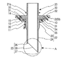
インサート部材であるチューブ取付部材20は、燃料タンク1のタンク外壁2を貫通する筒状部と、筒状部の外面に幅方向に張り出したフランジ部30を有する。筒状部は、タンク外壁2の外側に突出するタンク外筒部21と、タンク外壁2の内側に突出するタンク内筒部22から構成される。タンク外筒部21の外周には、フランジ部30に近接してタンク外筒突条部21aが形成されている。タンク外筒突条部21aは、タンク外筒部21にチューブを挿入するときに、チューブの先端のストッパーとなり、チューブを保持することができる。
The
タンク内筒部22は、フランジ部30に近接した、タンク内筒部根元部23と、タンク内筒部根元部23から先端方向に延設されたタンク内筒部突出部24から構成される。タンク内筒部根元部23は、タンク内筒部突出部24よりも厚肉に形成され、タンク内筒部突出部24が燃料タンク1内に突出しても、タンク内筒部突出部24を強固に保持することができる。また、溶融したパリソン50がタンク内筒部根元部23と融着しても、タンク内筒部根元部23が変形することがない。
The tank
タンク内筒部突出部24は、先端部分(図1にAで示した部分)は、後述するブロー成形時に、パリソン50を切り裂くことのできるパリソン切り裂き部25が形成されている。第1の実施の形態では、タンク内筒部突出部24の先端部分が斜めに切断され、切断された先端部分が鋭角状のパリソン切り裂き部25を形成している。
The tank inner
第1の実施の形態では、図2に示すように、パリソン切り裂き部25は、先端部分が斜めに切断されて鋭角状に形成された先端鋭利部27と、斜めに切断されたタンク内筒部突出部24の後端部分に形成され、タンク内筒部突出部24の筒壁に形成された平面部26と、先端鋭利部27と平面部26から連続してタンク内筒部突出部24の筒壁の両側に形成された斜面部28から形成される。
In the first embodiment, as shown in FIG. 2, the
後述するように、先端鋭利部27でパリソン50を切り裂き、平面部26で切り裂かれたパリソン50は、その一部がタンク外壁2を構成するパリソン50と切断されずに、連結されたまま保持することができるため、切断したパリソン50をパリソン切り裂き部25に付着させることがなく、チューブ取付部材20のフランジ部30やタンク内筒部根元部23に確実に融着されることができる。即ち、図1に示すように、先端鋭利部27で切り裂かれたパリソン50は、完全に切断されずに一部が連続しているため、タンク内筒部根元部23の外面と融着して、内筒カバー部11を構成する。
As will be described later, the
図3に示すように、フランジ部30は、タンク外筒部21とタンク内筒部22との境界部分の外周に円盤状に張り出して形成されている。
本発明の第1の実施の形態では、フランジ部30の内面側に、複数のフランジ突条部34を形成する。そのため、ブロー成形時に、フランジ部30の内面側であるフランジ下面部35に形成されたフランジ突条部34がパリソン50と接触して、フランジ突条部34の先端がパリソン50の熱で溶融して、フランジ突条部34とパリソン50が融着する。
このとき、パリソン切り裂き部25で切り裂かれたパリソン50は、タンク内筒部根元部23に融着するとともに、その一部がフランジ部30と融着する。
As shown in FIG. 3, the
In the first embodiment of the present invention, a plurality of
At this time, the
さらに、パリソン50が硬化した後は、タンク取付部10の部分において、フランジ部30の外面側であるフランジ上面部33をパリソン50で形成されたタンク外壁2の一部であるフランジカバー上部14が覆い、フランジ部30のフランジ下面部35をフランジカバー下部15で覆うことができ、フランジ部30を燃料タンク1のタンク外壁2の内部に埋設して、タンク外壁2のタンク取付部10でフランジ部30の全体を挟持するため、さらにフランジ部30を強固に保持することができる。従って、タンク外筒部21に外部から抜き、曲げ及び回転方向等の荷重が加わっても、チューブ取付部材20を確実に保持することができる。
Furthermore, after the
フランジ突条部34がパリソン50と融着するため、フランジ下面部35とフランジカバー下部15とが強固に固定されて、フランジ下面部35とフランジカバー下部15との間のシール性が向上するため、チューブ取付部材20とタンク外壁2との間から燃料蒸気等が漏れることがない。なお、フランジ突条部34は、一本或いは複数本形成することができる。
Since the
フランジ突条部34は、フランジ下面部35に円周状に複数本形成された場合には、フランジ下面部35の複数本のフランジ突条部34がパリソン50と融着して、フランジ下面部35とパリソン50が固着して、パリソン50が硬化後はフランジ下面部35とフランジカバー下部15との間のシール性が向上する。
When a plurality of
フランジ部30は、円周状に均等に複数のフランジ孔部31が形成することができる。フランジ孔部31を形成する場合には、フランジ孔部31にはブロー成形時にパリソン50を流入させて、フランジ部30の両面をパリソン50で融着し、パリソン50が硬化した後は、流入したパリソン50は、フランジ孔充填部13となり、タンク外壁2で融着して挟持している。
The
このとき、パリソン切り裂き部25で切り裂かれたパリソン50もその一部がフランジ孔部31に流入することができる。フランジ孔部31は円形に形成することができ、また3個以上多数、形成することができる。フランジ孔部31により、パリソン50がフランジ部30の両面に流入して、上述のフランジカバー上部14とフランジカバー下部15がフランジ部30を挟持し易くなる。
At this time, a part of the
このため、フランジ孔部31に流入したパリソン50が、フランジ部30の両面を覆うことができ、その両面を覆ったパリソン50をフランジ孔部31に存在するパリソン50で連結するため、フランジ部30を強固に保持することができるとともに、フランジ部30の両面をパリソン50で融着して挟持したため、フランジ部30とパリソン50の融着面積が大きくなり、タンク外壁2とパリソン50との融着強度が増大する。
Therefore, the
チューブ取付部材20は、フランジ部30の外面側に、根元付近に円周状にパリソン50が入り込むフランジ凹部32を形成することができる。この場合には、ブロー成形時に、フランジ部30の根元のフランジ凹部32まで確実にパリソン50を回り込ませることができる。そのため、フランジ部30の外面側に回り込んだフランジ凹部32の部分のパリソン50の先端部分をフランジ凹部32で保持して、パリソン50の硬化後は、フランジ部30の根元までタンク外壁2で確実に強固に挟持することができる。
The
次に、図4に基づき、本発明の第2の実施の形態であるチューブ取付部材20について説明する。
第2の実施の形態のチューブ取付部材20は、タンク内筒部22の寸法が第1の実施の形態よりも短く形成され、他の部分は第1の実施の形態と同様であるため、異なる部分のみを説明し、同等な部分の説明は省略する。
Next, based on FIG. 4, the
The
第2の実施の形態のチューブ取付部材20のタンク内筒部22は、タンク内筒部根元部23とタンク内筒部突出部24のいずれも第1の実施の形態よりも短く形成されているが、特にタンク内筒部突出部24を短く形成されている。また、タンク内筒部突出部24の先端に形成されたパリソン切り裂き部25の形状は、第1の実施の形態と同じである。これは、燃料タンク1の内部の構造により適宜、タンク内筒部22の寸法を調整するためである。そのため、第1の実施の形態よりも長くタンク内筒部22を形成することもできる。
この場合においても、パリソン切り裂き部25切り裂かれたパリソン50は、タンク内筒部根元部23に融着して、内筒カバー部11を形成している。
In the tank
Also in this case, the
次に、図5と図6に基づき、本発明の第3の実施の形態であるチューブ取付部材20について説明する。
第3の実施の形態のチューブ取付部材20は、タンク内筒部突出部24の先端に形成されたパリソン切り裂き部25の形状が第1の実施の形態と異なり、他の部分は第1の実施の形態と同様であるため、異なる部分のみを説明し、同等な部分の説明は省略する。
Next, based on FIG. 5 and FIG. 6, the
The
図6に示すように、第3の実施の形態では、パリソン切り裂き部25は、先端部分に4枚のパリソン切り裂き部25を有する。4枚以外に3枚或いは5枚等の他の複数枚にすることができる。その1枚のパリソン切り裂き部25は、図5に示すように直角三角形状に形成され、先端が先端鋭利部27を形成し、斜面が斜面部28を形成し、斜面と底辺の交点部分がタンク内筒部突出部24の先端の筒壁と一体になって、筒壁が平面部26を構成している。
As shown in FIG. 6, in the third embodiment, the
縦辺の部分は、4枚のパリソン切り裂き部25が一体に相互に結合されて、結合部分がタンク内筒部突出部24の中心線上に位置して、4枚のパリソン切り裂き部25の先端の先端鋭利部27も中心線上に一体に相互に結合されている。このため、パリソン50をタンク内筒部突出部24の中心部分で4枚の部分に切り裂くことができる。
In the vertical side portion, the four parison cut
先端鋭利部27で切り裂かれたパリソン50は、パリソン切り裂き部25の斜面部28でさらに、パリソン50を内筒部の外周まで確実に切り裂かれて、平面部26で4枚の切り裂かれたパリソン50となる。そして、切り裂かれたパリソン50をタンク内筒部突出部24の先端部分の平面部26において、パリソン50のタンク外壁2を構成する他の部分と連続するようにすることができ、切り裂いたパリソン50の部分をタンク内筒部根元部23とフランジ部30に均等に融着させることができる。
The
次に、図7と図8に基づき、インサート部材であるチューブ取付部材20をブロー成形品である燃料タンク1のタンク外壁2に取付ける方法について説明する。
タンク外壁2にチューブ取付部材20を取付けるには、燃料タンク1を成形するブロー成形金型40を使用して、燃料タンク1のブロー成形と同時に取付ける。
Next, based on FIG. 7 and FIG. 8, the method to attach the
In order to attach the
チューブ取付部材20をタンク外壁2に取付けるためには、ブロー成形金型40に、チューブ取付部材20のタンク外筒部21を嵌め込むインサート保持部42が形成され、インサート保持部42は、ブロー成形金型40のキャビティ面41に対して進退自在に移動するスライドコア43に取付けられている。スライドコア43は、チューブ取付部材20を取付けたときは、キャビティ面41より後退して、チューブ取付部材20のパリソン切り裂き部25の先端もキャビティ面41よりも後退している。
In order to attach the
次に、図7に示すように、ブロー成形金型40内に燃料タンク1のタンク外壁2を形成するパリソン50が導入される。そして、パリソン50はブロー成形金型40のキャビティ面41に当接する。このとき、チューブ取付部材20のタンク内筒部22は、キャビティ面41よりも後退しているため、パリソン50には接触していない。
Next, as shown in FIG. 7, a
その後、図8に示すように、スライドコア43が移動して、チューブ取付部材20のパリソン切り裂き部25がパリソン50を切り裂き、さらにスライドコア43が移動して、チューブ取付部材20のフランジ部3がパリソン50の内部に埋設されるまで移動する。
そして、タンク内筒部22は、パリソン50を突き破り、タンク外壁2の内部まで達する。
Thereafter, as shown in FIG. 8, the
Then, the tank
その後、パリソン50の内部に空気が吹き込まれてパリソン50はブロー成形金型40のキャビティ面41に押圧される。そうすると、パリソン50は、溶融状態にあるため、パリソン50とタンク内筒部22が融着するとともに、フランジ部30にも融着する。パリソン50はパリソン切り裂き部25に切り裂かれたパリソン50の一部は、タンク内筒部22のタンク内筒部根元部23に融着されて、内筒カバー部11を形成するとともに、フランジ部30の一部に融着する。そして、パリソン50は、フランジ部30を埋設して、フランジ孔部31にもパリソン50が進入して、パリソン50はフランジ部30と融着する。
Thereafter, air is blown into the interior of the
このため、フランジ部30の内面側とフランジカバー下部15とが強固に固定されて、フランジ部30の内面側とフランジカバー下部16との間のシール性が向上するため、チューブ取付部材20とタンク外壁2との間から燃料蒸気等が漏れることがない。なお、フランジ突条部34は、一本或いは複数本形成することができる。
Therefore, the inner surface side of the
さらに、パリソン50が硬化した後は、タンク取付部10の部分において、フランジ部30のフランジ上面部33をフランジカバー上部14が覆い、フランジ下面部35をフランジカバー下部16で覆ことができ、フランジ部30を燃料タンク1のタンク外壁2の内部に埋設して、タンク外壁2のタンク取付部10でフランジ部30の全体を挟持するため、さらにフランジ部30を強固に保持することができる。従って、タンク外筒部21に外部から抜き、曲げ及び回転方向等の荷重が加わっても、チューブ取付部材20を確実に保持することができる。
Further, after the
ブロー成形後は、スライドコア43は、チューブ取付部材20をタンク外壁2内に残して、後退する。
そうすると、パリソン50が硬化して、パリソン切り裂き部25で切り裂かれたパリソン50は、車内側保持リップ根元部41に融着して内筒カバー部11を形成し、フランジ部30を両面からフランジカバー上部14とフランジカバー下部15がフランジ孔充填部13により連結されて、挟持して、強固にチューブ取付部材20を保持することができる。
その後、ブロー成形金型40から燃料タンク1を取出して、ブロー成形が終了する。
この様にして、燃料タンク1のブロー成形と同時に、チューブ取付部材20をタンク外壁2に取付けることができる。
After blow molding, the
Then, the
Thereafter, the fuel tank 1 is taken out from the blow molding die 40, and the blow molding is completed.
In this way, the
1 燃料タンク
2 タンク外壁
10 タンク取付部
20 チューブ取付部材
21 タンク外筒部
22 タンク内筒部
25 パリソン切り裂き部
30 フランジ部
40 ブロー成形金型
50 パリソン
DESCRIPTION OF SYMBOLS 1
Claims (8)
上記インサート部材は、上記ブロー成形品の外壁を貫通する筒状部と、該筒状部の外面に幅方向に張り出したフランジ部を有し、該フランジ部は、上記ブロー成形品の外壁に埋設され、上記筒状部は、上記ブロー成形品の外側に張り出す外筒部と、上記ブロー成形品の内側に張り出す内筒部とを有し、
該内筒部は、先端部分がパリソン切り裂き部を有し、該パリソン切り裂き部は、その先端にパリソンを切り裂く先端鋭利部を形成し、該先端鋭利部よりも根元側の上記内筒部の筒壁の一部に平面部を有することを特徴とするインサート部材の取付構造。 In the insert member mounting structure in which at least a part of the insert member is embedded in the outer wall of the blow molded product,
The insert member has a cylindrical portion penetrating the outer wall of the blow molded product and a flange portion projecting in the width direction on the outer surface of the cylindrical portion, and the flange portion is embedded in the outer wall of the blow molded product. The cylindrical part has an outer cylindrical part projecting outside the blow molded product and an inner cylindrical part projecting inside the blow molded product,
The inner cylindrical portion has a parison cut portion at the tip portion, and the parison cut portion forms a sharp tip portion that cuts the parison at the tip, and the inner cylindrical portion at the root side of the sharp tip portion. A mounting structure for an insert member, wherein a part of the wall has a flat portion.
Priority Applications (1)
| Application Number | Priority Date | Filing Date | Title |
|---|---|---|---|
| JP2012260812A JP2014104693A (en) | 2012-11-29 | 2012-11-29 | Fitting structure of insert member of blow molded part |
Applications Claiming Priority (1)
| Application Number | Priority Date | Filing Date | Title |
|---|---|---|---|
| JP2012260812A JP2014104693A (en) | 2012-11-29 | 2012-11-29 | Fitting structure of insert member of blow molded part |
Publications (1)
| Publication Number | Publication Date |
|---|---|
| JP2014104693A true JP2014104693A (en) | 2014-06-09 |
Family
ID=51026584
Family Applications (1)
| Application Number | Title | Priority Date | Filing Date |
|---|---|---|---|
| JP2012260812A Pending JP2014104693A (en) | 2012-11-29 | 2012-11-29 | Fitting structure of insert member of blow molded part |
Country Status (1)
| Country | Link |
|---|---|
| JP (1) | JP2014104693A (en) |
Cited By (3)
| Publication number | Priority date | Publication date | Assignee | Title |
|---|---|---|---|---|
| JP2014231165A (en) * | 2013-05-28 | 2014-12-11 | キョーラク株式会社 | Insert part for blow molding |
| JP2015131552A (en) * | 2014-01-10 | 2015-07-23 | トヨタ自動車株式会社 | Fuel tank |
| US11534954B2 (en) | 2020-01-16 | 2022-12-27 | Volkswagen Aktiengesellschaft | Method and device for blow molding a plastic tank with at least one connection element penetrating the tank wall |
-
2012
- 2012-11-29 JP JP2012260812A patent/JP2014104693A/en active Pending
Cited By (3)
| Publication number | Priority date | Publication date | Assignee | Title |
|---|---|---|---|---|
| JP2014231165A (en) * | 2013-05-28 | 2014-12-11 | キョーラク株式会社 | Insert part for blow molding |
| JP2015131552A (en) * | 2014-01-10 | 2015-07-23 | トヨタ自動車株式会社 | Fuel tank |
| US11534954B2 (en) | 2020-01-16 | 2022-12-27 | Volkswagen Aktiengesellschaft | Method and device for blow molding a plastic tank with at least one connection element penetrating the tank wall |
Similar Documents
| Publication | Publication Date | Title |
|---|---|---|
| JP5495873B2 (en) | Automotive fuel tank | |
| JP5270911B2 (en) | Automotive fuel tank | |
| CN102131628B (en) | Process for manufacturing a plastic fuel tank and internal accessory | |
| JP5552425B2 (en) | How to secure accessories to a plastic fuel tank | |
| US9162390B2 (en) | Process for fastening an accessory to a plastic hollow body | |
| US8580064B2 (en) | Process for fastening an accessory to a plastic hollow body during the molding thereof and a connection piece | |
| US20150239198A1 (en) | Attaching structure of insert member to blow molded article | |
| EP2981427B1 (en) | A component for a vehicle plastic article such as a fuel tank | |
| US11021051B2 (en) | Liquid vehicle tank comprising a fastened component | |
| JP2014046676A (en) | Attachment structure for insert member of blow molding item | |
| JP2014104693A (en) | Fitting structure of insert member of blow molded part | |
| JP2015030117A (en) | Insert member fitting structure of blow-molded product | |
| JP2014043064A (en) | Structure for fitting an insert member to blow molded product | |
| US20200298696A1 (en) | Blow molded support for inlet check valve | |
| JP2019014292A (en) | Internal column attachment structure | |
| JP2006321309A (en) | Fuel tank for automobile and manufacturing method thereof | |
| JP2017087500A (en) | Insert member fitting structure for blow molded article | |
| JP2017087606A (en) | Insert member fitting method for blow molded article | |
| JP2018114856A (en) | Mounting method of filler pipe | |
| JP2018069701A (en) | Method for attaching synthetic resin part |