JP2014102332A - Image forming apparatus - Google Patents
Image forming apparatus Download PDFInfo
- Publication number
- JP2014102332A JP2014102332A JP2012253251A JP2012253251A JP2014102332A JP 2014102332 A JP2014102332 A JP 2014102332A JP 2012253251 A JP2012253251 A JP 2012253251A JP 2012253251 A JP2012253251 A JP 2012253251A JP 2014102332 A JP2014102332 A JP 2014102332A
- Authority
- JP
- Japan
- Prior art keywords
- voltage
- image carrier
- image
- unit
- current
- Prior art date
- Legal status (The legal status is an assumption and is not a legal conclusion. Google has not performed a legal analysis and makes no representation as to the accuracy of the status listed.)
- Granted
Links
Images


Classifications
-
- G—PHYSICS
- G03—PHOTOGRAPHY; CINEMATOGRAPHY; ANALOGOUS TECHNIQUES USING WAVES OTHER THAN OPTICAL WAVES; ELECTROGRAPHY; HOLOGRAPHY
- G03G—ELECTROGRAPHY; ELECTROPHOTOGRAPHY; MAGNETOGRAPHY
- G03G21/00—Arrangements not provided for by groups G03G13/00 - G03G19/00, e.g. cleaning, elimination of residual charge
- G03G21/20—Humidity or temperature control also ozone evacuation; Internal apparatus environment control
- G03G21/206—Conducting air through the machine, e.g. for cooling, filtering, removing gases like ozone
-
- G—PHYSICS
- G03—PHOTOGRAPHY; CINEMATOGRAPHY; ANALOGOUS TECHNIQUES USING WAVES OTHER THAN OPTICAL WAVES; ELECTROGRAPHY; HOLOGRAPHY
- G03G—ELECTROGRAPHY; ELECTROPHOTOGRAPHY; MAGNETOGRAPHY
- G03G21/00—Arrangements not provided for by groups G03G13/00 - G03G19/00, e.g. cleaning, elimination of residual charge
- G03G21/0094—Arrangements not provided for by groups G03G13/00 - G03G19/00, e.g. cleaning, elimination of residual charge fatigue treatment of the photoconductor
Landscapes
- Physics & Mathematics (AREA)
- General Physics & Mathematics (AREA)
- Life Sciences & Earth Sciences (AREA)
- Engineering & Computer Science (AREA)
- Atmospheric Sciences (AREA)
- Biodiversity & Conservation Biology (AREA)
- Ecology (AREA)
- Environmental & Geological Engineering (AREA)
- Environmental Sciences (AREA)
- Electrostatic Charge, Transfer And Separation In Electrography (AREA)
Abstract
【課題】湿度センサーを使用せずにエージング動作の実施時間を適切に決定することが可能な画像形成装置を提供する。
【解決手段】本発明は、像担持体7と、像担持体7を帯電させる帯電部材8と、トナー像を被転写体に転写する転写部材と、帯電部材8又は転写部材に電圧を印加する電圧印加部44と、帯電部材8又は転写部材に電圧が印加された際に流れる電流を測定する電流測定部45と、外気を像担持体7に吹き付けるファン23と、像担持体7からトナーを除去するクリーニング部材と、像担持体7にクリーニング部材を摺接させるエージング動作を画像形成前に実施する制御部40と、を備え、制御部40は、ファン23が像担持体7に外気を吹き付けると共に電圧印加部44が帯電部材8又は転写部材に電圧を印加した時に電流測定部45が測定する電流値が閾値以下の場合に、閾値を超える場合よりもエージング動作の実施時間を長くする。
【選択図】図4An image forming apparatus capable of appropriately determining an execution time of an aging operation without using a humidity sensor.
The present invention applies an voltage to an image carrier, a charging member for charging the image carrier, a transfer member for transferring a toner image to a transfer target, and the charging member or the transfer member. The voltage application unit 44, the current measurement unit 45 that measures the current that flows when a voltage is applied to the charging member 8 or the transfer member, the fan 23 that blows outside air onto the image carrier 7, and toner from the image carrier 7 A cleaning member to be removed, and a control unit 40 that performs an aging operation for sliding the cleaning member on the image carrier 7 before image formation. The control unit 40 causes the fan 23 to blow outside air onto the image carrier 7. In addition, when the voltage application unit 44 applies a voltage to the charging member 8 or the transfer member, when the current value measured by the current measurement unit 45 is equal to or less than the threshold value, the aging operation is performed longer than when the voltage value exceeds the threshold value.
[Selection] Figure 4
Description
本発明は、プリンター、複写機、ファクシミリ、複合機等の電子写真プロセスを用いた画像形成装置に関する。 The present invention relates to an image forming apparatus using an electrophotographic process, such as a printer, a copying machine, a facsimile machine, and a multifunction machine.
従来、電子写真プロセスを用いた画像形成装置は、像担持体(例えば、感光体ドラム)に担持されたトナー像を転写部材(例えば、転写ローラー)によって被転写体(例えば、用紙等の記録媒体や中間転写ベルト)に転写するように構成されている。このような構成の画像形成装置において、有機感光体、特に、電荷発生剤と電荷輸送剤を同一層内に有する単層型有機感光体を像担持体として用いる場合に、装置が数時間停止していた状態から画像形成動作を行うと、転写部材に含まれる揮発性物質が像担持体に及ぼす影響によって、画像に横筋が入ってしまうことがある。 2. Description of the Related Art Conventionally, an image forming apparatus using an electrophotographic process uses a transfer member (for example, a transfer roller) to transfer a toner image carried on an image carrier (for example, a photosensitive drum) to a transfer target (for example, a recording medium such as paper). Or an intermediate transfer belt). In an image forming apparatus having such a configuration, when an organic photoreceptor, in particular, a single-layer organic photoreceptor having a charge generator and a charge transport agent in the same layer is used as an image carrier, the apparatus stops for several hours. When the image forming operation is performed from the state where it has been, the image may have horizontal stripes due to the influence of the volatile substance contained in the transfer member on the image carrier.
このような画像不良は、機外が低温低湿である場合に特に発生し易いものであるが、像担持体を回転させながら像担持体の表面にクリーニング部材を摺接させるエージング動作を画像形成前に行っておくことで、防止することができる。しかしながら、このエージング動作を毎回一定時間実施すると、画像に横筋が入りにくいような場合(例えば、機外が高温高湿である場合)にもエージング動作が一定時間実施されることになり、ファーストプリントタイム(1回目の印刷が完了するまでの時間)が必要以上に長くなって、ユーザーにストレスを与えることになる。このような事態を回避するためには、温度や湿度を検知するセンサーからの情報に基づいて、必要な時間だけエージング動作を行うようにすることが考えられる(特許文献1の「温度及び湿度センサー9」参照)。 Such image defects are particularly likely to occur when the outside of the apparatus is at low temperature and low humidity. However, an aging operation in which the cleaning member is brought into sliding contact with the surface of the image carrier while rotating the image carrier is performed before image formation. This can be prevented by going to step 1. However, if this aging operation is performed for a certain period of time each time, the aging operation is performed for a certain period of time even when horizontal stripes are difficult to enter in the image (for example, when the outside of the apparatus is hot and humid), the first print The time (time until the first printing is completed) becomes longer than necessary, and stresses the user. In order to avoid such a situation, it is conceivable to perform an aging operation only for a necessary time based on information from a sensor for detecting temperature and humidity (see “Temperature and Humidity Sensors of Patent Document 1”). 9 ”).
しかしながら、湿度センサーは比較的高価な部品であるため、湿度センサーを使用すると、コストが上昇してしまう。そのため、特に低セグメント機(低価格機)において、更なる低価格化の要請に応えることが困難になる。 However, since the humidity sensor is a relatively expensive part, the use of the humidity sensor increases the cost. For this reason, it is difficult to meet the demand for further price reduction, particularly in low segment machines (low price machines).
そこで、本発明は上記事情を考慮し、湿度センサーを使用せずにエージング動作の実施時間を適切に決定し、画像に横筋が入るような画像不良の発生を抑制することが可能な画像形成装置を提供することを目的とする。 Therefore, in consideration of the above circumstances, the present invention appropriately determines the execution time of the aging operation without using a humidity sensor, and can suppress the occurrence of an image defect that causes horizontal stripes in the image. The purpose is to provide.
本発明の画像形成装置は、トナー像を担持する像担持体と、該像担持体を帯電させる帯電部材と、前記像担持体に担持されたトナー像を被転写体に転写する転写部材と、前記帯電部材又は前記転写部材の一方に電圧を印加する電圧印加部と、該電圧印加部が前記帯電部材又は前記転写部材の一方に電圧を印加した際に流れる電流を測定する電流測定部と、外気を機内に導入して前記像担持体に吹き付けるファンと、前記像担持体の表面からトナーを除去するクリーニング部材と、前記像担持体を回転させながら該像担持体の表面に前記クリーニング部材を摺接させるエージング動作を画像形成前に実施する制御部と、を備え、該制御部は、前記ファンが前記像担持体に外気を吹き付けると共に前記電圧印加部が前記帯電部材又は前記転写部材の一方に所定の電圧を印加した時に前記電流測定部が測定する電流値が所定の閾値以下である場合に、前記電流測定部が測定する電流値が所定の閾値を超える場合よりも、前記エージング動作の実施時間を長くすることを特徴とする。 The image forming apparatus of the present invention includes an image carrier that carries a toner image, a charging member that charges the image carrier, a transfer member that transfers the toner image carried on the image carrier to a transfer target, A voltage application unit that applies a voltage to one of the charging member or the transfer member; and a current measurement unit that measures a current flowing when the voltage application unit applies a voltage to one of the charging member or the transfer member; A fan that introduces outside air into the apparatus and blows it to the image carrier, a cleaning member that removes toner from the surface of the image carrier, and the cleaning member on the surface of the image carrier while rotating the image carrier. A control unit that performs an aging operation for sliding contact before image formation, and the control unit blows outside air to the image carrier and the voltage application unit is the charging member or the transfer member. When the current value measured by the current measurement unit when a predetermined voltage is applied to one side is less than or equal to a predetermined threshold, the aging operation is performed more than when the current value measured by the current measurement unit exceeds a predetermined threshold It is characterized in that the implementation time of is increased.
このような構成を採用することにより、湿度センサーを使用せずにエージング動作の実施時間を適切に決定し、画像に横筋が入るような画像不良の発生を抑制することができる。そのため、湿度センサーを使用してエージング動作の実施時間を決定する場合と比較して、コストを削減することが可能となり、低セグメント機における更なる低価格化の要請にも応えることが可能になる。 By adopting such a configuration, it is possible to appropriately determine the time for performing the aging operation without using a humidity sensor, and to suppress the occurrence of image defects such as horizontal stripes in the image. Therefore, it is possible to reduce costs compared to the case where the aging operation time is determined using a humidity sensor, and it is possible to meet the demand for further price reduction in low segment machines. .
本発明の画像形成装置は、前記ファンによって機内に導入される外気が吹き付けられる温度センサーを更に備え、前記制御部は、前記ファンが前記温度センサーに外気を吹き付けた時に前記温度センサーが検出する温度が所定の閾値以下である場合に、前記温度センサーが検出する温度が所定の閾値を超える場合よりも、前記エージング動作の実施時間を長くしても良い。 The image forming apparatus of the present invention further includes a temperature sensor that blows outside air introduced into the apparatus by the fan, and the control unit detects a temperature detected by the temperature sensor when the fan blows outside air to the temperature sensor. When the temperature is less than or equal to a predetermined threshold, the time for performing the aging operation may be longer than when the temperature detected by the temperature sensor exceeds the predetermined threshold.
このような構成を採用することにより、電流測定部が測定する電流値のみに基づいてエージング動作の実施時間を決定する場合よりも、エージング動作の実施時間をより一層適切に決定することが可能となる。 By adopting such a configuration, it is possible to determine the execution time of the aging operation more appropriately than when determining the execution time of the aging operation based only on the current value measured by the current measurement unit. Become.
前記温度センサーは、前記ファン側から前記像担持体側に向かって延びるダクト内に設けられていても良い。 The temperature sensor may be provided in a duct extending from the fan side toward the image carrier side.
このような構成を採用することにより、ファンによって機内に導入される外気を温度センサーに確実に吹き付けることが可能となり、これに伴って、温度センサーによって外気の温度を正確に検出することが可能となる。 By adopting such a configuration, it becomes possible to reliably blow the outside air introduced into the machine by the fan onto the temperature sensor, and accordingly, the temperature sensor can accurately detect the temperature of the outside air. Become.
本発明の画像形成装置は、前記帯電部材又は前記転写部材の他方に電圧を印加する他の電圧印加部を更に備え、前記制御部は、前記ファンが前記像担持体に外気を吹き付けると共に前記電圧印加部が前記帯電部材又は前記転写部材の一方に所定の電圧を印加した時に前記電流測定部が測定する電流値が所定の基準値以下である場合に、前記電流測定部が測定する電流値が所定の基準値を超える場合よりも、画像形成時に前記帯電部材に印加される電圧を大きくすると共に、画像形成時に前記転写部材に印加される電圧を小さくしても良い。 The image forming apparatus of the present invention further includes another voltage application unit that applies a voltage to the other of the charging member or the transfer member, and the control unit is configured to blow the outside air onto the image carrier and to When the current value measured by the current measurement unit is less than or equal to a predetermined reference value when the application unit applies a predetermined voltage to one of the charging member or the transfer member, the current value measured by the current measurement unit is The voltage applied to the charging member at the time of image formation may be increased and the voltage applied to the transfer member at the time of image formation may be decreased as compared to a case where a predetermined reference value is exceeded.
このような構成を採用することで、画像形成時に、機外の湿度に最も適した電圧を帯電部材及び転写部材に印加することが可能になるため、出力画像の画質を高めることができる。 By adopting such a configuration, it becomes possible to apply a voltage most suitable for the humidity outside the apparatus to the charging member and the transfer member during image formation, so that the image quality of the output image can be improved.
本発明の画像形成装置は、前記像担持体にトナーを供給する現像部材と、該現像部材にバイアスを印加するバイアス印加部と、を更に備え、前記制御部は、前記ファンが前記像担持体に外気を吹き付けると共に前記電圧印加部が前記帯電部材又は前記転写部材の一方に所定の電圧を印加した時に前記電流測定部が測定する電流値が所定の基準値以下である場合に、前記電流測定部が測定する電流値が所定の基準値を超える場合よりも、画像形成時に前記現像部材に印加されるバイアスのduty比を大きくしても良い。 The image forming apparatus of the present invention further includes a developing member that supplies toner to the image carrier, and a bias applying unit that applies a bias to the developing member, and the control unit has the fan supported by the image carrier. The current measurement is performed when the current value measured by the current measurement unit when the voltage application unit applies a predetermined voltage to one of the charging member or the transfer member and the current measurement unit is less than or equal to a predetermined reference value. The duty ratio of the bias applied to the developing member during image formation may be made larger than when the current value measured by the unit exceeds a predetermined reference value.
このような構成を採用することで、画像形成時に、機外の湿度に最も適したバイアスを現像部材に印加することができ、出力画像の画質を高めることができる。 By adopting such a configuration, a bias most suitable for the humidity outside the apparatus can be applied to the developing member during image formation, and the image quality of the output image can be improved.
前記像担持体は、電荷発生剤と電荷輸送剤を同一層内に含有する単層型有機感光体によって構成されても良い。 The image carrier may be composed of a single layer type organic photoreceptor containing a charge generating agent and a charge transporting agent in the same layer.
このような構成を採用することで、積層型有機感光体によって構成される像担持体を用いる場合よりも、電流測定部によって測定される電流値が機外の湿度の変化に伴って大きく変動するため、機外の湿度を把握しやすくなる。 By adopting such a configuration, the current value measured by the current measuring unit varies greatly with changes in humidity outside the apparatus, compared to the case where an image carrier constituted by a stacked organic photoconductor is used. Therefore, it becomes easy to grasp the humidity outside the machine.
本発明によれば、湿度センサーを使用せずにエージング動作の実施時間を適切に決定し、画像に横筋が入るような画像不良の発生を抑制することが可能となる。 According to the present invention, it is possible to appropriately determine the execution time of the aging operation without using a humidity sensor, and to suppress the occurrence of image defects such as horizontal stripes in the image.
まず、図1を用いて、画像形成装置としてのプリンター1の構成の概略について説明する。図1は、本発明の一実施形態に係るプリンターの概略を示す模式図である。以下、図1における紙面右側を、プリンター1の正面側(前側)とする。なお、図1〜図3の矢印Frは、プリンター1の正面側(前側)を示している。 First, an outline of a configuration of a printer 1 as an image forming apparatus will be described with reference to FIG. FIG. 1 is a schematic diagram showing an outline of a printer according to an embodiment of the present invention. Hereinafter, the right side in FIG. 1 is the front side (front side) of the printer 1. The arrow Fr in FIGS. 1 to 3 indicates the front side (front side) of the printer 1.
プリンター1は、プリンター本体2を備えており、プリンター本体2の下部には被転写体としての用紙(図示せず)を収納する給紙カセット3が設けられ、プリンター本体2の上端には排紙トレイ4が設けられている。
The printer 1 includes a printer
プリンター本体2の前部には、レーザー・スキャニング・ユニット(LSU)で構成される露光器5が配置され、プリンター本体2の後部には、画像形成部6が設けられている。画像形成部6には、像担持体としての感光体ドラム7が回転可能に設けられており、感光体ドラム7の周囲には、帯電部材としての帯電ローラー8と、トナーコンテナ9に接続された現像装置10と、転写部材としての転写ローラー11と、クリーニング装置12と、除電ランプ18とが、感光体ドラム7の回転方向(図1の矢印X参照)に沿って配置されている。
An
プリンター本体2の後部には、下方から上方に向かって用紙の搬送経路13が設けられている。即ち、プリンター1は、用紙が下方から上方に向かって搬送される縦搬送方式である。搬送経路13の上流端には給紙部14が設けられ、搬送経路13の中流部には、感光体ドラム7と転写ローラー11によって構成される転写部15が設けられ、搬送経路13の下流部には定着装置16が設けられている。搬送経路13の後側には、両面印刷用の反転経路17が設けられている。
A
次に、このような構成を備えたプリンター1の画像形成動作について説明する。 Next, an image forming operation of the printer 1 having such a configuration will be described.
プリンター1に電源が投入されると、各種パラメーターが初期化され、定着装置16の温度設定等の初期設定が実行される。そして、プリンター1に接続されたコンピューター等から画像データが入力され、印刷開始の指示がなされると、以下のようにして画像形成動作が実行される。
When the printer 1 is turned on, various parameters are initialized, and initial setting such as temperature setting of the
まず、帯電ローラー8によって感光体ドラム7の表面が均一に帯電された後、露光器5からのレーザー光(図1の矢印P参照)により感光体ドラム7に対して画像データに対応した露光が行われ、感光体ドラム7の表面に静電潜像が形成される。次に、トナーコンテナ9から供給されるトナー(現像剤)によって、現像装置10が静電潜像を現像する。これにより、感光体ドラム7にトナー像が担持される。
First, after the surface of the photosensitive drum 7 is uniformly charged by the
一方、給紙部14によって給紙カセット3から取り出された用紙は、上記した画像形成動作とタイミングを合わせて転写部15へと搬送される。そして、感光体ドラム7に担持されたトナー像が転写ローラー11によって用紙に転写される。トナー像を転写された用紙は、搬送経路13を下流側へと搬送されて定着装置16に進入し、この定着装置16において用紙にトナー像が定着される。トナー像が定着された用紙は、搬送経路13の下流端から排紙トレイ4に排出される。なお、感光体ドラム7上に残留したトナーと電荷は、クリーニング装置12と除電ランプ18によってそれぞれ除去される。
On the other hand, the paper taken out from the paper feed cassette 3 by the
次に、図2、図3を用いて、プリンター本体2と、画像形成部6と、について更に詳細に説明する。
Next, the printer
まず、プリンター本体2及びその周辺部材について説明する。図2に示されるように、プリンター本体2の左端部(図2における手前側の端部)には、画像形成部6の左端部を覆うように左カバー20が設けられている。なお、図2では、左カバー20の後部が切り欠き表示されている。左カバー20の下部には、複数のルーバー21によって構成される通気口22が設けられている。
First, the printer
プリンター本体2の左端部には、左カバー20の通気口22の内側(右側)にファン23が設置されている。そして、ファン23が起動(回転)すると、外気が機内に導入されるように構成されている。
A
プリンター本体2の内部には、ダクト24が設けられている。ダクト24は、ファン23側から感光体ドラム7側に向かって延びており、ファン23によって機内に導入された外気を感光体ドラム7へと誘導するように構成されている(図2の白抜き矢印参照)。ダクト24内の上流端部(ファン23に最も近い部分)には、温度センサー25が設けられている。温度センサー25は、例えばサーミスターによって構成される。なお、プリンター本体2には、湿度センサーは搭載されていない。
A
次に、画像形成部6について説明する。画像形成部6は、プリンター本体2に収容されており、側面視においてファン23と定着装置16の間に配置されている。図3に示されるように、画像形成部6は、感光体ドラム7と、感光体ドラム7の前方に配置される帯電ローラー8と、感光体ドラム7の前下方に配置される現像装置10と、感光体ドラム7の後方に配置される転写ローラー11と、感光体ドラム7の上方に配置されるクリーニング装置12と、感光体ドラム7の前上方に配置される除電ランプ18と、を備えている。
Next, the
感光体ドラム7は、左右方向(図3では紙面奥行き方向)に長い形状を成している。感光体ドラム7は、電荷発生剤と電荷輸送剤を同一層内に含有する単層型有機感光体によって構成される。上記の電荷発生剤としては、例えば、フタロシアニン系顔料、ペレリン系顔料、ビスアゾ顔料、ジチオケトピロロピロール顔料、無金属ナフタロシアニン顔料、金属ナフタロシアニン顔料、スクアライン顔料、トリスアゾ顔料、インジゴ顔料、アズレニウム顔料、シアニン顔料、セレン、セレン−テルル、アモルファスシリコン、ピリリウム塩、アンサンスロン系顔料、トリフェニルメタン系顔料、スレン系顔料、トルイジン系顔料、ピラゾリン系顔料、キナクリドン系顔料等を用いることができる。また、上記の電荷輸送剤としては、例えば、オキサジアゾール系化合物、スチリル系化合物、カルバゾール系化合物、有機ポリシラン化合物、ピラゾリン系化合物、ヒドラゾン系化合物、トリフェニルアミン系化合物、インドール系化合物、オキサゾール系化合物、イソオキサゾール系化合物、チアゾール系化合物、チアジアゾール系化合物、イミダゾール系化合物、ピラゾール系化合物、トリアゾール系化合物等の含窒素環式化合物、縮合多環式化合物等を用いることができる。 The photosensitive drum 7 has a long shape in the left-right direction (the depth direction in FIG. 3). The photoreceptor drum 7 is constituted by a single layer type organic photoreceptor containing a charge generating agent and a charge transporting agent in the same layer. Examples of the charge generator include phthalocyanine pigments, perelin pigments, bisazo pigments, dithioketopyrrolopyrrole pigments, metal-free naphthalocyanine pigments, metal naphthalocyanine pigments, squaraine pigments, trisazo pigments, indigo pigments, and azurenium pigments. Cyanine pigments, selenium, selenium-tellurium, amorphous silicon, pyrylium salts, ansanthrone pigments, triphenylmethane pigments, selenium pigments, toluidine pigments, pyrazoline pigments, quinacridone pigments, and the like can be used. Examples of the charge transport agent include oxadiazole compounds, styryl compounds, carbazole compounds, organic polysilane compounds, pyrazoline compounds, hydrazone compounds, triphenylamine compounds, indole compounds, and oxazole compounds. Compounds, isoxazole compounds, thiazole compounds, thiadiazole compounds, imidazole compounds, pyrazole compounds, triazole compounds, and other nitrogen-containing cyclic compounds, condensed polycyclic compounds, and the like can be used.
帯電ローラー8は、左右方向に長い形状を成している。帯電ローラー8は、例えば、エピクロルヒドリンを主成分とするソリッドゴムローラーによって構成されている。帯電ローラー8は、感光体ドラム7に当接している。帯電ローラー8は、感光体ドラム7と一体化されてドラムユニット27を構成している。ドラムユニット27は、プリンター本体2に対して着脱可能に設けられている。
The charging
現像装置10は、箱型形状の現像装置本体28と、現像装置本体28に収容される前後一対の攪拌部材30と、後側の攪拌部材30の後上方に配置され、感光体ドラム7と対向する現像部材としての現像ローラー31と、を備えている。そして、トナーコンテナ9(図1参照)から排出されたトナーが攪拌部材30によって攪拌された後、現像ローラー31によって感光体ドラム7に供給されるようになっている。
The developing
転写ローラー11は、例えば、エピクロルヒドリンを主成分とする発泡ゴムローラーによって構成されている。転写ローラー11は、感光体ドラム7に当接している。
The
クリーニング装置12は、箱型形状のフレーム部材32と、このフレーム部材32に支持されるクリーニング部材としてのクリーニングブレード33と、フレーム部材32に収容される回収スパイラル34と、を備えている。回収スパイラル34は、クリーニング装置12外に設けられたトナー回収ボックス(図示せず)に接続されている。そして、クリーニングブレード33によって感光体ドラム7の表面から除去されたトナーが、回収スパイラル34によって回収され、トナー回収ボックスへと搬送されるようになっている。
The
除電ランプ18は、感光体ドラム7の回転方向において帯電ローラー8の上流側に配置されている。除電ランプ18は、プリント基板上に複数の発光素子(例えば赤色LED)を列設させることで構成されており、各発光素子から感光体ドラム7上に除電光を照射して、感光体ドラム7の表面電位を除去できるようになっている。
The
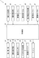
次に、図4を用いて、プリンター1の制御システムについて説明する。 Next, the control system of the printer 1 will be described with reference to FIG.
プリンター1には、制御部40(CPU)が設けられている。制御部40は、ROM、RAM等の記憶装置で構成される記憶部41と接続されており、記憶部41に格納された制御プログラムや制御用データに基づいて、制御部40がプリンター1の各部の制御を行うように構成されている。記憶部41は、帯電ローラー8に流れ込む電流の閾値Ith(例えば、2μA)と、温度センサー25によって検出される温度の閾値Tth(例えば、23℃)と、を記憶している。
The printer 1 is provided with a control unit 40 (CPU). The
制御部40は、プリンター本体2に設けられた操作表示部42と接続されている。操作表示部42には、例えば、スタートキー、ストップ/クリアキー、電源キー、テンキー、タッチパネル等の操作キーが設けられ、ユーザーが各操作キーを操作すると、その操作指示が制御部40に出力されるように構成されている。
The
制御部40は、温度センサー25に接続されている。そして、温度センサー25が検出した温度が、制御部40に出力されるようになっている。
The
制御部40は、バイアス印加部43に接続されており、バイアス印加部43は、現像ローラー31に接続されている。そして、バイアス印加部43から現像ローラー31に付与されるバイアスを、制御部40が制御するように構成されている。
The
制御部40は、ファン23に接続されている。そして、制御部40からの信号に基づいてファン23が回転するように構成されている。
The
制御部40は、電圧印加部44に接続されており、電圧印加部44は、帯電ローラー8に接続されている。そして、電圧印加部44から帯電ローラー8に印加される電圧を、制御部40が制御するように構成されている。電圧印加部44と帯電ローラー8の間には、電流測定部45が直列に接続されている。電流測定部45は、電圧印加部44が帯電ローラー8に電圧を印加した際に電圧印加部44から帯電ローラー8に流れる電流を測定し、その測定結果を制御部40に出力するように構成されている。
The
制御部40は、他の電圧印加部46に接続されており、他の電圧印加部46は、転写ローラー11に接続されている。そして、他の電圧印加部46から転写ローラー11に印加される電圧を、制御部40が制御するように構成されている。
The
制御部40は、駆動モーター47に接続されている。駆動モーター47は、感光体ドラム7、帯電ローラー8、現像ローラー31等の回転部材に接続されている。そして、制御部40からの信号に基づいて駆動モーター47が上記各回転部材を回転させるように構成されている。
The
次に、上記のように構成されたものにおいて、電圧印加部44から帯電ローラー8への流れ込み電流値(以下、単に「流れ込み電流値」と称する。)と機外の温湿度との関係について、図5を用いて説明する。
Next, in the configuration configured as described above, the relationship between the current flowing from the
図5に示されるように、流れ込み電流値は、機外の湿度が高ければ高い程、大きくなる。このことから、流れ込み電流値が所定の閾値以下である場合には、流れ込み電流値が所定の閾値を超える場合よりも機外の湿度が低く、画像に横筋が入るような画像不良が発生しやすいことが分かる。また、流れ込み電流値が所定の閾値を超える場合には、流れ込み電流値が所定の閾値以下である場合よりも機外の湿度が高く、画像に横筋が入るような画像不良が発生しにくいことが分かる。なお、図5からは、流れ込み電流値は、機外の温度が高ければ高い程、大きくなることも分かる。 As shown in FIG. 5, the flow-in current value increases as the humidity outside the apparatus increases. Therefore, when the inflow current value is equal to or lower than the predetermined threshold, the external humidity is lower than that in the case where the inflow current value exceeds the predetermined threshold, and image defects such as horizontal stripes are likely to occur in the image. I understand that. Further, when the inflow current value exceeds a predetermined threshold, the humidity outside the apparatus is higher than when the inflow current value is equal to or less than the predetermined threshold, and image defects such as horizontal stripes appear less likely to occur in the image. I understand. FIG. 5 also shows that the flow-in current value increases as the outside temperature increases.
次に、上記のように構成されたものにおいて、画像形成前に行われるエージング制御について、主に図6及び図2を用いて説明する。 Next, aging control performed before image formation in the configuration configured as described above will be described mainly with reference to FIGS. 6 and 2.
まず、プリンター1が起動すると、感光体ドラム7が回転し、ファン23が起動する(ステップS101)。このファン23の起動により、外気が機内に導入され、図2に白抜き矢印で示されるように、ダクト24内に設けられた温度センサー25に吹き付けられる。また、ダクト24内に流入した外気は、図2に白抜き矢印で示されるように、ダクト24内をファン23側から感光体ドラム7側へと流れて、感光体ドラム7に吹き付けられる。
First, when the printer 1 is activated, the photosensitive drum 7 is rotated and the
ファン23を起動させてから一定時間(例えば5秒間)が経過し、ファン23によって機内に導入された外気が上記のように温度センサー25及び感光体ドラム7に吹き付けられると、電圧印加部44が帯電ローラー8に所定の電圧(例えば1250V)を印加する(ステップS102)。そして、この時に帯電ローラー8に流れ込む電流値Iを電流測定部45が測定すると共に、ファン23によって導入される外気の温度Tを温度センサー25が検出する(ステップS103)。
When a certain time (for example, 5 seconds) elapses after the
次に、電流測定部45によって測定された電流値Iが記憶部41に記憶された閾値Ith以下であるか否かを制御部40が判定する(ステップS104)。このステップS104がNOの場合には、制御部40は、エージング動作をt1秒間(例えば、5秒間)実施する(ステップS105)。このエージング動作においては、感光体ドラム7を回転させながら感光体ドラム7の表面にクリーニングブレード33を摺接させる。これにより、転写ローラー11に含まれる揮発性物質が感光体ドラム7に与える影響が緩和され、画像に横筋が入るような画像不良の発生が抑制されて、良好な出力画像を得ることが可能になる。
Next, it is determined that the
一方で、ステップS104がYESの場合には、温度センサー25によって検出された温度Tが記憶部41に記憶された閾値Tth以下であるか否かを制御部40が判定する(ステップS106)。このステップS106がNOの場合には、制御部40は、エージング動作をt1秒間行う(ステップS105)。
On the other hand, when step S104 is YES, the
一方で、ステップS106がYESの場合には、制御部40は、上記のt1秒間よりも長いt2秒間(例えば、30秒間)、エージング動作を行う(ステップS107)。
On the other hand, when step S106 is YES, the
本実施形態では前述のように、ファン23が感光体ドラム7に外気を吹き付けると共に電圧印加部44が帯電ローラー8に所定の電圧を印加した時に電流測定部45が測定する電流値Iが閾値Ith以下である場合に、電流測定部45が測定する電流値Iが所定の閾値Ithを超える場合よりも、エージング動作の実施時間を長くしている。このような構成を採用することで、湿度センサーを使用せずにエージング動作の実施時間を適切に決定し、画像に横筋が入るような画像不良の発生を抑制することができる。そのため、湿度センサーを使用してエージング動作の実施時間を決定する場合と比較して、コストを削減することが可能となり、低セグメント機における更なる低価格化の要請にも応えることが可能になる。
In the present embodiment, as described above, the current value I measured by the
また、機外の湿度が一定値以下であり、画像に横筋が入るような画像不良が発生しやすい場合には、機外の湿度が一定値を超える場合よりも長い時間エージング動作が行われることになる。これに伴って、画像に横筋が入るような画像不良が発生するのを確実に防止することが可能となる。一方で、機外の湿度が一定値を超えており、画像に横筋が入るような画像不良が発生しにくい場合には、機外の湿度が一定値以下の場合よりもエージング動作が短縮される。これに伴って、ファーストプリントタイムを短縮して、ユーザーのストレスを軽減することが可能となる。 Also, if the humidity outside the machine is below a certain value and image defects such as horizontal stripes appear in the image, the aging operation should be performed for a longer time than when the humidity outside the machine exceeds a certain value. become. Along with this, it is possible to reliably prevent the occurrence of image defects that cause horizontal stripes in the image. On the other hand, when the humidity outside the machine exceeds a certain value and image defects such as horizontal stripes are unlikely to occur, the aging operation is shortened compared to when the humidity outside the machine is below a certain value. . As a result, the first print time can be shortened to reduce the user's stress.
また、本実施形態では上記のように、ファン23が温度センサー25に外気を吹き付けた時に温度センサー25が検出する温度Tが所定の閾値Tth以下である場合に、温度センサー25が検出する温度Tが所定の閾値Tthを超える場合よりも、エージング動作の実施時間を長くしている。このような構成を採用することで、電流測定部45が測定する電流値Iのみに基づいてエージング動作の実施時間を決定する場合よりも、エージング動作の実施時間をより一層適切に決定することが可能となる。
Further, in the present embodiment, as described above, the temperature detected by the
また、機外の温度が一定値以下であり、画像に横筋が入るような画像不良が発生しやすい場合には、機外の温度が一定値を超える場合よりも長い時間エージング動作が行われることになる。これに伴って、画像に横筋が入るような画像不良が発生するのを確実に防止することが可能となる。一方で、機外の温度が一定値を超えており、画像に横筋が入るような画像不良が発生しにくい場合には、機外の温度が一定値以下の場合よりもエージング動作が短縮される。これに伴って、ファーストプリントタイムを短縮して、ユーザーのストレスを軽減することが可能となる。 Also, if the temperature outside the machine is below a certain value and image defects such as horizontal stripes are likely to occur, the aging operation will be performed for a longer time than when the outside temperature exceeds a certain value. become. Along with this, it is possible to reliably prevent the occurrence of image defects that cause horizontal stripes in the image. On the other hand, when the temperature outside the machine exceeds a certain value and it is difficult for image defects such as horizontal stripes to appear in the image, the aging operation is shortened compared to when the temperature outside the machine is below a certain value. . As a result, the first print time can be shortened to reduce the user's stress.
また、温度センサー25は、ファン23側から感光体ドラム7側に向かって延びるダクト24内に設けられている。そのため、ファン23によって機内に導入される外気を温度センサー25に確実に吹き付けることが可能となり、これに伴って、温度センサー25によって外気の温度を正確に検出することが可能となる。
The
また、電荷発生剤と電荷輸送剤を同一層内に含有する単層型有機感光体によって感光体ドラム7が構成されているため、積層型有機感光体によって感光体ドラム7が構成される場合よりも、電流測定部45によって測定される電流値Iが機外の湿度の変化に伴って大きく変動する。そのため、機外の湿度を把握しやすくなる。
Further, since the photosensitive drum 7 is constituted by a single layer type organic photoreceptor containing a charge generating agent and a charge transporting agent in the same layer, the case where the photosensitive drum 7 is constituted by a laminated type organic photoreceptor. However, the current value I measured by the
ところで、上記のように電荷発生剤と電荷輸送剤を同一層内に含有する単一層型感光体を感光体ドラム7として用いる場合には、機外の湿度によって帯電効率や転写効率が大きく変動する。そこで、本実施形態では、ファン23が感光体ドラム7に外気を吹き付けると共に電圧印加部44が帯電ローラー8に所定の電圧を印加した時に電流測定部45が測定する電流値Iに基づいて、画像形成時に電圧印加部44が帯電ローラー8に印加する電圧及び他の電圧印加部46が転写ローラー11に印加する電圧を決定している。具体的には、ファン23が感光体ドラム7に外気を吹き付けると共に電圧印加部44が帯電ローラー8に所定の電圧を印加した時に電流測定部45が測定する電流値Iが所定の基準値IS1(例えば、2μA)以下の場合には、上記の電流値Iが所定の基準値IS1を超える場合よりも、電圧印加部44から帯電ローラー8に印加する電圧を大きくすると共に、他の電圧印加部46から転写ローラー11に印加する電圧を小さくするようになっている。
By the way, when a single layer type photoreceptor containing a charge generating agent and a charge transporting agent in the same layer as described above is used as the photoreceptor drum 7, the charging efficiency and the transfer efficiency greatly vary depending on the humidity outside the apparatus. . Therefore, in the present embodiment, the image is generated based on the current value I measured by the
このような構成を採用することで、機外の湿度に最も適した電圧を電圧印加部44から帯電ローラー8に印加することが可能になると共に、機外の湿度に最も適した電圧を他の電圧印加部46から転写ローラー11に印加することが可能になる。そのため、出力画像の画質を高めることができる。また、電圧印加部44から帯電ローラー8に印加する電圧及び他の電圧印加部46から転写ローラー11に印加する電圧を機外の湿度に基づいて決定するため、これらの電圧を記憶するためのROMをドラムユニット27に装着しておく必要が無い。この点においても、コストの削減を図ることが可能となる。
By adopting such a configuration, it becomes possible to apply the voltage most suitable for the humidity outside the apparatus from the
また、本実施形態では、ファン23が感光体ドラム7に外気を吹き付けると共に電圧印加部44が帯電ローラー8に所定の電圧を印加した時に電流測定部45が測定する電流値Iに基づいて、バイアス印加部43が現像ローラー31に印加するバイアス(ACバイアス)を決定している。具体的には、ファン23が感光体ドラム7に外気を吹き付けると共に電圧印加部44が帯電ローラー8に所定の電圧を印加した時に電流測定部45が測定する電流値Iが所定の基準値IS2(例えば、2μA)以下の場合には、上記の電流値Iが所定の基準値IS2を超える場合よりも、バイアス印加部43が現像ローラー31に印加するバイアスのduty比を大きくするようになっている。このような構成を採用することで、機外の湿度に最も適したバイアスをバイアス印加部43から現像ローラー31に印加することができ、出力画像の画質を高めることができる。
In the present embodiment, the bias is applied based on the current value I measured by the
本実施形態では、電流測定部45によって測定された電流値Iが記憶部41に記憶された閾値Ith以下であり、且つ、温度センサー25によって検出された温度Tが記憶部41に記憶された閾値Tth以下である場合に、電流測定部45によって測定された電流値Iが記憶部41に記憶された閾値Ithを超えている場合及び温度センサー25によって検出された温度Tが記憶部41に記憶された閾値Tthを超えている場合よりもエージング動作の実施時間を長くする場合について説明した。一方で、他の異なる実施形態では、電流測定部45によって測定された電流値Iが記憶部41に記憶された閾値Ith以下であるか、又は、温度センサー25によって検出された温度Tが記憶部41に記憶された閾値Tth以下である場合に、電流測定部45によって測定された電流値Iが記憶部41に記憶された閾値Ithを超え、且つ、温度センサー25によって検出された温度Tが記憶部41に記憶された閾値Tthを超えている場合よりもエージング動作の実施時間を長くしても良い。つまり、電流測定部45によって測定された電流値Iが記憶部41に記憶された閾値Ith以下であることと、温度センサー25によって検出された温度Tが記憶部41に記憶された閾値Tth以下であることは、and条件であっても良いし、or条件であっても良い。
In the present embodiment, the current value I measured by the
本実施形態では、エージング制御の際、電圧印加部44から帯電ローラー8に所定の電圧を印加する場合について説明したが、他の異なる実施形態では、エージング制御の際、他の電圧印加部46から転写ローラー11に所定の電圧を印加しても良い。
In the present embodiment, the case where a predetermined voltage is applied from the
本実施形態では、ファン23が感光体ドラム7に外気を吹き付けると共に電圧印加部44が帯電ローラー8に所定の電圧を印加した時に帯電ローラー8に流れる電流を電流測定部45によって測定した。一方で、他の異なる実施形態では、ファン23が感光体ドラム7に外気を吹き付けると共に電圧印加部44が帯電ローラー8に所定の電圧を印加した時に転写ローラー11に流れる電流や、感光体ドラム7に流れる電流を測定しても良い。
In the present embodiment, the
本実施形態では、エージング動作として感光体ドラム7を回転させながら感光体ドラム7の表面にクリーニングブレード33を摺接させる場合について説明したが、他の異なる実施形態では、エージング動作中に、上記した感光体ドラム7へのクリーニングブレード33の摺接に加えて、現像ローラー31から感光体ドラム7にトナーを供給したり、電圧印加部44から帯電ローラー8に電圧を印加したりしても良い。このような構成を採用することで、場合によっては、転写ローラー11に含まれる揮発性物質が感光体ドラム7に与える影響を一層効率的に緩和して、エージング動作の所要時間を短くすることが可能となる。
In this embodiment, the case where the
本実施形態では、閾値Ithと閾値Tthを各々1個ずつ設定したが、他の異なる実施形態では、閾値Ithと閾値Tthを複数個ずつ設定しても良い。換言すると、本実施形態では、エージング動作の実施時間をt1とt2の2段階で切り替える場合について説明したが、他の異なる実施形態では、エージング動作の実施時間を3段階以上の多段階で切り替えても良い。このような構成を採用することで、機外の温湿度に合わせて必要最低限の時間だけエージング動作を実施することが可能となり、ファーストプリントタイムを一層短縮して、ユーザーのストレスを一層軽減することができる。なお、更に他の異なる実施形態では、電流値Iが閾値Ith以下の場合や温度Tが閾値Tth以下の場合に、エージング動作の実施時間を0としても良い。 In the present embodiment has been set by each one of the threshold value I th and the threshold value T th, in other different embodiments, it may be set a threshold value I th and the threshold value T th by plurality. In other words, in this embodiment, the case where the execution time of the aging operation is switched in two stages, t1 and t2, has been described, but in another different embodiment, the execution time of the aging operation is switched in multiple stages of three or more stages. Also good. By adopting such a configuration, it is possible to perform the aging operation for the minimum necessary time according to the temperature and humidity outside the machine, further reducing the first print time and further reducing the stress on the user. be able to. Incidentally, yet another different embodiment, in the case or if the temperature T current value I is less than the threshold value I th in the following threshold value T th, the execution time of the aging operation may be 0.
本実施形態では、帯電部材として帯電ローラー8を用いる場合について説明したが、他の異なる実施形態では、帯電ブラシ等の他の形状の帯電部材を用いても良い。
Although the case where the charging
本実施形態では、温度センサー25をダクト24内に配置する場合について説明したが、他の異なる実施形態では、ダクト24の外部(例えば、ダクト24から分岐させた他のダクト内やファン23とダクト24の間の空間)に温度センサー25を配置しても良い。
In the present embodiment, the case where the
本実施形態では、用紙を被転写体としたが、他の異なる実施形態においてタンデム式の画像形成装置を用いるような場合には、中間転写ベルトを被転写体としても良い。 In this embodiment, the sheet is the transfer target. However, in the case where a tandem image forming apparatus is used in another different embodiment, the intermediate transfer belt may be the transfer target.
本実施形態では、プリンター1に本発明の構成を適用する場合について説明したが、他の異なる実施形態では、複写機、ファクシミリ、複合機等のプリンター1以外の画像形成装置に本発明の構成を適用しても良い。 In the present embodiment, the case where the configuration of the present invention is applied to the printer 1 has been described. However, in another different embodiment, the configuration of the present invention is applied to an image forming apparatus other than the printer 1 such as a copying machine, a facsimile machine, or a multifunction peripheral. It may be applied.
1 プリンター(画像形成装置)
7 感光体ドラム(像担持体)
8 帯電ローラー(帯電部材)
11 転写ローラー(転写部材)
23 ファン
24 ダクト
25 温度センサー
31 現像ローラー(現像部材)
33 クリーニングブレード(クリーニング部材)
40 制御部
43 バイアス印加部
44 電圧印加部
45 電流測定部
46 他の電圧印加部
1 Printer (image forming device)
7 Photosensitive drum (image carrier)
8 Charging roller (charging member)
11 Transfer roller (transfer member)
23
33 Cleaning blade (cleaning member)
40
Claims (6)
該像担持体を帯電させる帯電部材と、
前記像担持体に担持されたトナー像を被転写体に転写する転写部材と、
前記帯電部材又は前記転写部材の一方に電圧を印加する電圧印加部と、
該電圧印加部が前記帯電部材又は前記転写部材の一方に電圧を印加した際に流れる電流を測定する電流測定部と、
外気を機内に導入して前記像担持体に吹き付けるファンと、
前記像担持体の表面からトナーを除去するクリーニング部材と、
前記像担持体を回転させながら該像担持体の表面に前記クリーニング部材を摺接させるエージング動作を画像形成前に実施する制御部と、を備え、
該制御部は、前記ファンが前記像担持体に外気を吹き付けると共に前記電圧印加部が前記帯電部材又は前記転写部材の一方に所定の電圧を印加した時に前記電流測定部が測定する電流値が所定の閾値以下である場合に、前記電流測定部が測定する電流値が所定の閾値を超える場合よりも、前記エージング動作の実施時間を長くすることを特徴とする画像形成装置。 An image carrier for carrying a toner image;
A charging member for charging the image carrier;
A transfer member for transferring the toner image carried on the image carrier to the transfer body;
A voltage application unit that applies a voltage to one of the charging member or the transfer member;
A current measuring unit for measuring a current flowing when the voltage applying unit applies a voltage to one of the charging member or the transfer member;
A fan that introduces outside air into the machine and blows it onto the image carrier;
A cleaning member for removing toner from the surface of the image carrier;
A control unit that performs an aging operation for sliding the cleaning member on the surface of the image carrier while rotating the image carrier before image formation;
The control unit has a predetermined current value measured by the current measurement unit when the fan blows outside air onto the image carrier and the voltage application unit applies a predetermined voltage to one of the charging member or the transfer member. When the current value measured by the current measuring unit exceeds a predetermined threshold value, the time for performing the aging operation is made longer than when the current value measured by the current measuring unit exceeds a predetermined threshold value.
前記制御部は、前記ファンが前記温度センサーに外気を吹き付けた時に前記温度センサーが検出する温度が所定の閾値以下である場合に、前記温度センサーが検出する温度が所定の閾値を超える場合よりも、前記エージング動作の実施時間を長くすることを特徴とする請求項1に記載の画像形成装置。 A temperature sensor that blows outside air introduced into the machine by the fan;
When the temperature detected by the temperature sensor is equal to or lower than a predetermined threshold when the fan blows outside air to the temperature sensor, the control unit is more than the case where the temperature detected by the temperature sensor exceeds a predetermined threshold. The image forming apparatus according to claim 1, wherein an execution time of the aging operation is extended.
前記制御部は、前記ファンが前記像担持体に外気を吹き付けると共に前記電圧印加部が前記帯電部材又は前記転写部材の一方に所定の電圧を印加した時に前記電流測定部が測定する電流値が所定の基準値以下である場合に、前記電流測定部が測定する電流値が所定の基準値を超える場合よりも、画像形成時に前記帯電部材に印加される電圧を大きくすると共に、画像形成時に前記転写部材に印加される電圧を小さくすることを特徴とする請求項1〜3のいずれか1項に記載の画像形成装置。 Further comprising another voltage application unit for applying a voltage to the other of the charging member or the transfer member;
The control unit has a predetermined current value measured by the current measurement unit when the fan blows outside air onto the image carrier and the voltage application unit applies a predetermined voltage to one of the charging member or the transfer member. When the current value measured by the current measuring unit exceeds a predetermined reference value, the voltage applied to the charging member during image formation is increased and the transfer during image formation is performed. The image forming apparatus according to claim 1, wherein a voltage applied to the member is reduced.
該現像部材にバイアスを印加するバイアス印加部と、を更に備え、
前記制御部は、前記ファンが前記像担持体に外気を吹き付けると共に前記電圧印加部が前記帯電部材又は前記転写部材の一方に所定の電圧を印加した時に前記電流測定部が測定する電流値が所定の基準値以下である場合に、前記電流測定部が測定する電流値が所定の基準値を超える場合よりも、画像形成時に前記現像部材に印加されるバイアスのduty比を大きくすることを特徴とする請求項1〜4のいずれか1項に記載の画像形成装置。 A developing member for supplying toner to the image carrier;
A bias applying unit that applies a bias to the developing member;
The control unit has a predetermined current value measured by the current measurement unit when the fan blows outside air onto the image carrier and the voltage application unit applies a predetermined voltage to one of the charging member or the transfer member. When the current value measured by the current measuring unit exceeds a predetermined reference value, the duty ratio of the bias applied to the developing member during image formation is increased when the current value measured by the current measuring unit exceeds a predetermined reference value. The image forming apparatus according to any one of claims 1 to 4.
Priority Applications (2)
| Application Number | Priority Date | Filing Date | Title |
|---|---|---|---|
| JP2012253251A JP5712191B2 (en) | 2012-11-19 | 2012-11-19 | Image forming apparatus |
| US14/083,155 US9122243B2 (en) | 2012-11-19 | 2013-11-18 | Image forming apparatus |
Applications Claiming Priority (1)
| Application Number | Priority Date | Filing Date | Title |
|---|---|---|---|
| JP2012253251A JP5712191B2 (en) | 2012-11-19 | 2012-11-19 | Image forming apparatus |
Related Child Applications (1)
| Application Number | Title | Priority Date | Filing Date |
|---|---|---|---|
| JP2015009034A Division JP5891317B2 (en) | 2015-01-21 | 2015-01-21 | Image forming apparatus |
Publications (2)
| Publication Number | Publication Date |
|---|---|
| JP2014102332A true JP2014102332A (en) | 2014-06-05 |
| JP5712191B2 JP5712191B2 (en) | 2015-05-07 |
Family
ID=50728056
Family Applications (1)
| Application Number | Title | Priority Date | Filing Date |
|---|---|---|---|
| JP2012253251A Expired - Fee Related JP5712191B2 (en) | 2012-11-19 | 2012-11-19 | Image forming apparatus |
Country Status (2)
| Country | Link |
|---|---|
| US (1) | US9122243B2 (en) |
| JP (1) | JP5712191B2 (en) |
Families Citing this family (6)
| Publication number | Priority date | Publication date | Assignee | Title |
|---|---|---|---|---|
| US9285701B2 (en) * | 2012-10-16 | 2016-03-15 | Kyocera Document Solutions Inc. | Image forming apparatus including an image carrier, a charging member, a voltage applying part, a current measuring part and a controlling part |
| JP5891317B2 (en) * | 2015-01-21 | 2016-03-22 | 京セラドキュメントソリューションズ株式会社 | Image forming apparatus |
| US9791828B2 (en) * | 2015-05-19 | 2017-10-17 | Ricoh Company, Ltd. | Image forming apparatus including a blower to perform an operation based on a detection result of the a detector |
| CN109471339B (en) * | 2017-09-08 | 2021-08-27 | 京瓷办公信息系统株式会社 | Image forming apparatus with a toner supply device |
| JP2021058012A (en) * | 2019-09-30 | 2021-04-08 | キヤノン株式会社 | Electronic device |
| JP7631948B2 (en) * | 2021-03-22 | 2025-02-19 | ブラザー工業株式会社 | Image forming device |
Citations (3)
| Publication number | Priority date | Publication date | Assignee | Title |
|---|---|---|---|---|
| JPH08335025A (en) * | 1995-06-09 | 1996-12-17 | Hitachi Koki Co Ltd | Photosensitive drum cooling device in electrophotographic printing device |
| JP2002351134A (en) * | 2001-05-23 | 2002-12-04 | Canon Inc | Image forming device |
| JP2008216750A (en) * | 2007-03-06 | 2008-09-18 | Kyocera Mita Corp | Charging controller for image forming apparatus |
Family Cites Families (9)
| Publication number | Priority date | Publication date | Assignee | Title |
|---|---|---|---|---|
| JP4324692B2 (en) | 2004-04-15 | 2009-09-02 | 独立行政法人産業技術総合研究所 | Hydrogen activity measuring device |
| JP4751681B2 (en) * | 2004-11-12 | 2011-08-17 | 株式会社リコー | Image forming apparatus |
| JP5111830B2 (en) * | 2006-10-26 | 2013-01-09 | 京セラドキュメントソリューションズ株式会社 | Image forming apparatus |
| US7899352B2 (en) * | 2007-03-06 | 2011-03-01 | Kyocera Mita Corporation | Image forming apparatus |
| JP2008298890A (en) * | 2007-05-29 | 2008-12-11 | Sharp Corp | Developer, developing unit, developing device, and image forming apparatus |
| JP5009097B2 (en) * | 2007-08-30 | 2012-08-22 | 株式会社リコー | Image forming apparatus |
| US7725050B2 (en) * | 2008-09-19 | 2010-05-25 | Xerox Corporation | Heated drum assembly having a multiple speed fan for use in a printer |
| JP6012957B2 (en) * | 2010-12-10 | 2016-10-25 | キヤノンファインテック株式会社 | Image forming apparatus |
| US8948669B2 (en) * | 2012-03-15 | 2015-02-03 | Fuji Xerox Co., Ltd. | Transfer device and image forming apparatus |
-
2012
- 2012-11-19 JP JP2012253251A patent/JP5712191B2/en not_active Expired - Fee Related
-
2013
- 2013-11-18 US US14/083,155 patent/US9122243B2/en not_active Expired - Fee Related
Patent Citations (3)
| Publication number | Priority date | Publication date | Assignee | Title |
|---|---|---|---|---|
| JPH08335025A (en) * | 1995-06-09 | 1996-12-17 | Hitachi Koki Co Ltd | Photosensitive drum cooling device in electrophotographic printing device |
| JP2002351134A (en) * | 2001-05-23 | 2002-12-04 | Canon Inc | Image forming device |
| JP2008216750A (en) * | 2007-03-06 | 2008-09-18 | Kyocera Mita Corp | Charging controller for image forming apparatus |
Also Published As
| Publication number | Publication date |
|---|---|
| US9122243B2 (en) | 2015-09-01 |
| US20140140713A1 (en) | 2014-05-22 |
| JP5712191B2 (en) | 2015-05-07 |
Similar Documents
| Publication | Publication Date | Title |
|---|---|---|
| JP5712191B2 (en) | Image forming apparatus | |
| JP4355002B2 (en) | Image forming apparatus | |
| JP2007219454A (en) | Waste toner recovering device and image forming apparatus | |
| JP5754467B2 (en) | Developing device and image forming apparatus | |
| JP4613215B2 (en) | Image forming apparatus | |
| JP2015025915A (en) | Image forming apparatus, and method of measuring surface potential of photosensitive layer | |
| JP4890810B2 (en) | Image forming apparatus | |
| JP5891317B2 (en) | Image forming apparatus | |
| JP5454496B2 (en) | Image forming apparatus | |
| JP5206767B2 (en) | Image forming apparatus | |
| JP4558048B2 (en) | Transfer device and image forming apparatus having the same | |
| JP2016018179A (en) | Image forming device | |
| JP7172240B2 (en) | Image forming apparatus and program | |
| JP6131470B2 (en) | Image forming apparatus | |
| JP5114345B2 (en) | Image forming apparatus | |
| JP6958219B2 (en) | Image forming device and image forming method | |
| JP2009053397A (en) | Image forming apparatus | |
| JP2010020246A (en) | Image forming apparatus | |
| JP2016130830A (en) | Image forming apparatus | |
| CN109541909B (en) | Image forming apparatus and method of controlling image forming apparatus | |
| JP2009151068A (en) | Image forming apparatus | |
| JP5929392B2 (en) | Image forming apparatus | |
| JP6805976B2 (en) | Image forming device | |
| JP7158821B2 (en) | Image forming apparatus and control method | |
| JP2003241515A (en) | Image forming device |
Legal Events
| Date | Code | Title | Description |
|---|---|---|---|
| A621 | Written request for application examination |
Free format text: JAPANESE INTERMEDIATE CODE: A621 Effective date: 20140919 |
|
| A871 | Explanation of circumstances concerning accelerated examination |
Free format text: JAPANESE INTERMEDIATE CODE: A871 Effective date: 20140919 |
|
| A975 | Report on accelerated examination |
Free format text: JAPANESE INTERMEDIATE CODE: A971005 Effective date: 20141111 |
|
| A131 | Notification of reasons for refusal |
Free format text: JAPANESE INTERMEDIATE CODE: A131 Effective date: 20141125 |
|
| A521 | Written amendment |
Free format text: JAPANESE INTERMEDIATE CODE: A523 Effective date: 20150121 |
|
| TRDD | Decision of grant or rejection written | ||
| A01 | Written decision to grant a patent or to grant a registration (utility model) |
Free format text: JAPANESE INTERMEDIATE CODE: A01 Effective date: 20150210 |
|
| A61 | First payment of annual fees (during grant procedure) |
Free format text: JAPANESE INTERMEDIATE CODE: A61 Effective date: 20150309 |
|
| R150 | Certificate of patent or registration of utility model |
Ref document number: 5712191 Country of ref document: JP Free format text: JAPANESE INTERMEDIATE CODE: R150 |
|
| LAPS | Cancellation because of no payment of annual fees |