JP2014052554A - Reflective screen and video image display system - Google Patents
Reflective screen and video image display system Download PDFInfo
- Publication number
- JP2014052554A JP2014052554A JP2012197878A JP2012197878A JP2014052554A JP 2014052554 A JP2014052554 A JP 2014052554A JP 2012197878 A JP2012197878 A JP 2012197878A JP 2012197878 A JP2012197878 A JP 2012197878A JP 2014052554 A JP2014052554 A JP 2014052554A
- Authority
- JP
- Japan
- Prior art keywords
- screen
- layer
- diffusion layer
- reflective screen
- light
- Prior art date
- Legal status (The legal status is an assumption and is not a legal conclusion. Google has not performed a legal analysis and makes no representation as to the accuracy of the status listed.)
- Granted
Links
- 238000009792 diffusion process Methods 0.000 claims abstract description 197
- 230000009471 action Effects 0.000 claims description 27
- 230000031700 light absorption Effects 0.000 claims description 15
- 238000002834 transmittance Methods 0.000 claims description 7
- 239000000758 substrate Substances 0.000 claims description 5
- 239000010410 layer Substances 0.000 description 330
- 239000011347 resin Substances 0.000 description 47
- 229920005989 resin Polymers 0.000 description 47
- 235000019557 luminance Nutrition 0.000 description 32
- 239000002344 surface layer Substances 0.000 description 26
- 239000000463 material Substances 0.000 description 17
- 230000000052 comparative effect Effects 0.000 description 13
- 230000000694 effects Effects 0.000 description 10
- 239000000049 pigment Substances 0.000 description 9
- 230000008859 change Effects 0.000 description 8
- 238000007740 vapor deposition Methods 0.000 description 8
- 238000010586 diagram Methods 0.000 description 7
- 238000009826 distribution Methods 0.000 description 7
- 238000004519 manufacturing process Methods 0.000 description 7
- 239000005020 polyethylene terephthalate Substances 0.000 description 7
- 229920000139 polyethylene terephthalate Polymers 0.000 description 7
- 239000004925 Acrylic resin Substances 0.000 description 6
- BQCADISMDOOEFD-UHFFFAOYSA-N Silver Chemical compound [Ag] BQCADISMDOOEFD-UHFFFAOYSA-N 0.000 description 6
- 230000000873 masking effect Effects 0.000 description 6
- 229910052751 metal Inorganic materials 0.000 description 6
- 239000002184 metal Substances 0.000 description 6
- 239000002245 particle Substances 0.000 description 6
- 229910052709 silver Inorganic materials 0.000 description 6
- 239000004332 silver Substances 0.000 description 6
- 239000000853 adhesive Substances 0.000 description 5
- 230000001070 adhesive effect Effects 0.000 description 5
- 229910052782 aluminium Inorganic materials 0.000 description 5
- XAGFODPZIPBFFR-UHFFFAOYSA-N aluminium Chemical compound [Al] XAGFODPZIPBFFR-UHFFFAOYSA-N 0.000 description 5
- UHESRSKEBRADOO-UHFFFAOYSA-N ethyl carbamate;prop-2-enoic acid Chemical compound OC(=O)C=C.CCOC(N)=O UHESRSKEBRADOO-UHFFFAOYSA-N 0.000 description 5
- 229920000178 Acrylic resin Polymers 0.000 description 4
- KAKZBPTYRLMSJV-UHFFFAOYSA-N Butadiene Chemical compound C=CC=C KAKZBPTYRLMSJV-UHFFFAOYSA-N 0.000 description 4
- PPBRXRYQALVLMV-UHFFFAOYSA-N Styrene Chemical compound C=CC1=CC=CC=C1 PPBRXRYQALVLMV-UHFFFAOYSA-N 0.000 description 4
- 238000011156 evaluation Methods 0.000 description 4
- 238000005259 measurement Methods 0.000 description 4
- 238000000034 method Methods 0.000 description 4
- 230000003287 optical effect Effects 0.000 description 4
- 239000003973 paint Substances 0.000 description 4
- 229920002284 Cellulose triacetate Polymers 0.000 description 3
- NNLVGZFZQQXQNW-ADJNRHBOSA-N [(2r,3r,4s,5r,6s)-4,5-diacetyloxy-3-[(2s,3r,4s,5r,6r)-3,4,5-triacetyloxy-6-(acetyloxymethyl)oxan-2-yl]oxy-6-[(2r,3r,4s,5r,6s)-4,5,6-triacetyloxy-2-(acetyloxymethyl)oxan-3-yl]oxyoxan-2-yl]methyl acetate Chemical compound O([C@@H]1O[C@@H]([C@H]([C@H](OC(C)=O)[C@H]1OC(C)=O)O[C@H]1[C@@H]([C@@H](OC(C)=O)[C@H](OC(C)=O)[C@@H](COC(C)=O)O1)OC(C)=O)COC(=O)C)[C@@H]1[C@@H](COC(C)=O)O[C@@H](OC(C)=O)[C@H](OC(C)=O)[C@H]1OC(C)=O NNLVGZFZQQXQNW-ADJNRHBOSA-N 0.000 description 3
- 239000011324 bead Substances 0.000 description 3
- 238000000465 moulding Methods 0.000 description 3
- 229920003207 poly(ethylene-2,6-naphthalate) Polymers 0.000 description 3
- 239000011112 polyethylene naphthalate Substances 0.000 description 3
- -1 polyethylene terephthalate Polymers 0.000 description 3
- 230000002829 reductive effect Effects 0.000 description 3
- 229920001187 thermosetting polymer Polymers 0.000 description 3
- 230000000007 visual effect Effects 0.000 description 3
- VVQNEPGJFQJSBK-UHFFFAOYSA-N Methyl methacrylate Chemical compound COC(=O)C(C)=C VVQNEPGJFQJSBK-UHFFFAOYSA-N 0.000 description 2
- PXHVJJICTQNCMI-UHFFFAOYSA-N Nickel Chemical compound [Ni] PXHVJJICTQNCMI-UHFFFAOYSA-N 0.000 description 2
- 238000000576 coating method Methods 0.000 description 2
- 238000004040 coloring Methods 0.000 description 2
- 239000004744 fabric Substances 0.000 description 2
- 239000011888 foil Substances 0.000 description 2
- 238000005286 illumination Methods 0.000 description 2
- 230000001965 increasing effect Effects 0.000 description 2
- 230000005865 ionizing radiation Effects 0.000 description 2
- 230000004048 modification Effects 0.000 description 2
- 238000012986 modification Methods 0.000 description 2
- 239000012466 permeate Substances 0.000 description 2
- 239000012994 photoredox catalyst Substances 0.000 description 2
- 239000004417 polycarbonate Substances 0.000 description 2
- 230000009467 reduction Effects 0.000 description 2
- VYZAMTAEIAYCRO-UHFFFAOYSA-N Chromium Chemical compound [Cr] VYZAMTAEIAYCRO-UHFFFAOYSA-N 0.000 description 1
- 239000004820 Pressure-sensitive adhesive Substances 0.000 description 1
- XUIMIQQOPSSXEZ-UHFFFAOYSA-N Silicon Chemical compound [Si] XUIMIQQOPSSXEZ-UHFFFAOYSA-N 0.000 description 1
- 238000010521 absorption reaction Methods 0.000 description 1
- 230000003373 anti-fouling effect Effects 0.000 description 1
- 230000008901 benefit Effects 0.000 description 1
- 230000015572 biosynthetic process Effects 0.000 description 1
- 229910052804 chromium Inorganic materials 0.000 description 1
- 239000011651 chromium Substances 0.000 description 1
- 239000011248 coating agent Substances 0.000 description 1
- 238000005520 cutting process Methods 0.000 description 1
- 238000000151 deposition Methods 0.000 description 1
- 238000001514 detection method Methods 0.000 description 1
- 230000006866 deterioration Effects 0.000 description 1
- 238000007607 die coating method Methods 0.000 description 1
- 238000010894 electron beam technology Methods 0.000 description 1
- 230000002708 enhancing effect Effects 0.000 description 1
- 239000003822 epoxy resin Substances 0.000 description 1
- 238000001125 extrusion Methods 0.000 description 1
- 230000002349 favourable effect Effects 0.000 description 1
- 238000011049 filling Methods 0.000 description 1
- 238000001746 injection moulding Methods 0.000 description 1
- 239000010954 inorganic particle Substances 0.000 description 1
- 230000002452 interceptive effect Effects 0.000 description 1
- 230000001678 irradiating effect Effects 0.000 description 1
- 238000010030 laminating Methods 0.000 description 1
- 238000002156 mixing Methods 0.000 description 1
- 229910052759 nickel Inorganic materials 0.000 description 1
- 230000036961 partial effect Effects 0.000 description 1
- 230000000149 penetrating effect Effects 0.000 description 1
- 230000002093 peripheral effect Effects 0.000 description 1
- 229920005668 polycarbonate resin Polymers 0.000 description 1
- 229920000647 polyepoxide Polymers 0.000 description 1
- 238000012805 post-processing Methods 0.000 description 1
- 238000003825 pressing Methods 0.000 description 1
- KCTAWXVAICEBSD-UHFFFAOYSA-N prop-2-enoyloxy prop-2-eneperoxoate Chemical compound C=CC(=O)OOOC(=O)C=C KCTAWXVAICEBSD-UHFFFAOYSA-N 0.000 description 1
- 230000001681 protective effect Effects 0.000 description 1
- 239000011241 protective layer Substances 0.000 description 1
- 238000010298 pulverizing process Methods 0.000 description 1
- 238000011160 research Methods 0.000 description 1
- 238000007650 screen-printing Methods 0.000 description 1
- 238000007493 shaping process Methods 0.000 description 1
- 239000010703 silicon Substances 0.000 description 1
- 229910052710 silicon Inorganic materials 0.000 description 1
- 238000005507 spraying Methods 0.000 description 1
- 238000003892 spreading Methods 0.000 description 1
- 230000007480 spreading Effects 0.000 description 1
- 238000004544 sputter deposition Methods 0.000 description 1
- 229920005992 thermoplastic resin Polymers 0.000 description 1
Images


Landscapes
- Overhead Projectors And Projection Screens (AREA)
- Optical Elements Other Than Lenses (AREA)
- Transforming Electric Information Into Light Information (AREA)
Abstract
Description
本発明は、投射された映像光を反射して表示する反射スクリーン、及び、これを備える映像表示システムに関するものである。 The present invention relates to a reflection screen that reflects and displays projected image light, and an image display system including the same.
近年、反射スクリーンに映像を投射する映像源として、至近距離から比較的大きな入射角度で映像光を投写して大画面表示を実現する短焦点型の映像投射装置(プロジェクタ)等が広く利用されている。このような短焦点型の映像投射装置は、反射スクリーンに対して、上方又は下方から従来の映像源よりも大きな入射角度で映像光を投射することができ、反射スクリーンを用いた映像表示システムの省スペース化等に寄与している。
このような短焦点型の映像投射装置によって投射された映像光を良好に表示するために、単位レンズが複数配列されて形成されたリニアフレネルレンズ形状やサーキュラーフレネルレンズ形状を有するレンズ層の表面に反射層を形成した反射スクリーン等が様々に開発されている(例えば、特許文献1,2)。
In recent years, as a video source for projecting an image on a reflective screen, a short focus type video projection device (projector) that projects a video light at a relatively large incident angle from a close distance to realize a large screen display has been widely used. Yes. Such a short focus type image projection device can project image light at a larger incident angle than the conventional image source from above or below on the reflection screen. This contributes to space saving.
In order to satisfactorily display the image light projected by such a short focus type image projection device, the surface of the lens layer having a linear Fresnel lens shape or a circular Fresnel lens shape formed by arranging a plurality of unit lenses is used. Various reflective screens and the like on which a reflective layer is formed have been developed (for example,
上述のような反射スクリーンでは、一般に、画面の上下方向及び左右方向において、必要な視野角を確保するために、光を拡散する拡散層を備えている。
一般に、反射スクリーンや各種映像表示装置等においては、画面上下方向の視野角に比べて、画面左右方向の視野角を広くすることが好ましく、また、画面上下方向の視野角はある程度狭い範囲としても映像の視認に大きな影響はない。
In general, the reflection screen as described above includes a diffusion layer that diffuses light in order to ensure a necessary viewing angle in the vertical and horizontal directions of the screen.
In general, in a reflective screen, various video display devices, etc., it is preferable to widen the viewing angle in the horizontal direction of the screen compared to the viewing angle in the vertical direction of the screen. There is no big influence on visual recognition.
拡散層として、光を等方的に拡散する等方性拡散層を用いた場合、画面上下方向においては視野角が大きく広がりすぎ、一方、画面左右方向の視野角が狭く、不十分となるという問題がある。また、画面上下方向において、光が不要な範囲にまで拡散されることにより、映像の輝度が低下するという問題がある。
これに対して、特定の角度方向から入射した光を拡散し、それ以外の角度から入射する光は透過するという異方性拡散層のみを用いた場合、視野角特性の変化が急峻となり、所定の角度範囲外からは、十分な視野が得られない場合がある。
上述の特許文献1,2には、十分な視野角特性を得るための対策に関してなんら開示されていない。
また、コントラストが高く、かつ、明るい映像を表示することは、反射スクリーンやこれを用いた映像表示システムにおいて、常々求められることである。
When an isotropic diffusion layer that diffuses light isotropically is used as the diffusion layer, the viewing angle is too wide in the vertical direction of the screen, while the viewing angle in the horizontal direction of the screen is narrow and insufficient. There's a problem. In addition, in the vertical direction of the screen, there is a problem that the luminance of the video is lowered due to the light being diffused to an unnecessary range.
On the other hand, when only an anisotropic diffusion layer that diffuses light incident from a specific angle direction and transmits light incident from other angles is used, the change in viewing angle characteristics becomes steep and predetermined. From outside this angular range, a sufficient field of view may not be obtained.
The above-mentioned
In addition, displaying a bright image with high contrast is always required in a reflective screen and an image display system using the same.
本発明の課題は、十分な視野角を有し、かつ、明るく、コントラストの高い良好な映像を表示できる反射スクリーン、及び、これを備える映像表示システムを提供することである。 An object of the present invention is to provide a reflective screen that has a sufficient viewing angle and can display a good image with high brightness and high contrast, and an image display system including the same.
本発明は、以下のような解決手段により、前記課題を解決する。なお、理解を容易にするために、本発明の実施形態に対応する符号を付して説明するが、これに限定されるものではない。
請求項1の発明は、映像源(LS)から投影された映像光を反射させて観察可能に表示する反射スクリーン(10,20)であって、レンズ面(132)と非レンズ面(133)とを有し背面側に凸となる単位レンズ(131)が複数配列されたフレネルレンズ形状を背面側に有するレンズ層(13)と、少なくとも前記単位レンズの前記レンズ面に形成され、光を反射する反射層(12,22)と、該反射スクリーンの厚み方向において前記レンズ層よりも映像源側に配置され、光の入射角に依らず光を等方的に拡散して透過する作用を有する等方性拡散層(16)と、該反射スクリーンの厚み方向において前記レンズ層よりも映像源側に配置され、スクリーン面に平行な第1の方向及び前記スクリーン面の法線方向に平行な断面において第1の角度範囲(A1)内の入射角で入射した光を拡散して透過し、前記第1の角度範囲外の入射角で入射した光を拡散せずに透過する作用を有する第1異方性拡散層(15)と、該反射スクリーンの厚み方向において前記レンズ層よりも映像源側に配置され、前記第1の方向及び前記スクリーン面の法線方向に平行な断面において、前記スクリーン面の法線方向を軸として前記第1の角度範囲と対称な第2の角度範囲(A2)内の入射角で入射した光を拡散して透過し、前記第2の角度範囲外の入射角で入射した光を拡散せずに透過する作用を有する第2異方性拡散層(14)と、を備える反射スクリーン(10,20)である。
請求項2の発明は、請求項1に記載の反射スクリーンにおいて、前記第1の方向は、該反射スクリーンの画面左右方向であること、を特徴とする反射スクリーン(10,20)である。
請求項3の発明は、請求項1又は請求項2に記載の反射スクリーンにおいて、該反射スクリーンの厚み方向において前記レンズ層よりも映像源側に配置され、該反射スクリーンの剛性を維持し、該反射スクリーンの他の層よりも厚さが厚い基板層(17)を備えること、を特徴とする反射スクリーン(10)である。
請求項4の発明は、請求項3項に記載の反射スクリーンにおいて、前記基板層(17)は、所定の透過率となるように着色されていること、を特徴とする反射スクリーン(10)である。
請求項5の発明は、請求項1から請求項4までのいずれか1項に記載の反射スクリーンにおいて、少なくとも前記非レンズ面(133)には、光を吸収する光吸収層(11)が形成されていること、を特徴とする反射スクリーン(10)である。
請求項6の発明は、請求項1から請求項5までのいずれか1項に記載の反射スクリーン(10,20)と、前記反射スクリーンに映像光を投射する映像源(LS)と、を備える映像表示システム(1)である。
The present invention solves the above problems by the following means. In addition, in order to make an understanding easy, although the code | symbol corresponding to embodiment of this invention is attached | subjected and demonstrated, it is not limited to this.
The invention of
A second aspect of the present invention is the reflective screen according to the first aspect, wherein the first direction is a horizontal direction of the screen of the reflective screen.
According to a third aspect of the present invention, in the reflective screen according to the first or second aspect, the reflective screen is disposed closer to the image source than the lens layer in the thickness direction of the reflective screen, and maintains the rigidity of the reflective screen, A reflective screen (10) characterized in that it comprises a substrate layer (17) that is thicker than the other layers of the reflective screen.
A fourth aspect of the present invention is the reflective screen according to the third aspect, wherein the substrate layer (17) is colored so as to have a predetermined transmittance. is there.
According to a fifth aspect of the present invention, in the reflective screen according to any one of the first to fourth aspects, a light absorbing layer (11) that absorbs light is formed at least on the non-lens surface (133). A reflective screen (10) characterized in that
The invention of claim 6 comprises the reflecting screen (10, 20) according to any one of
本発明によれば、十分な視野角を有し、かつ、明るく、コントラストの高い良好な映像を表示できる反射スクリーン、及び、これを備える映像表示システムとすることができる。 ADVANTAGE OF THE INVENTION According to this invention, it can be set as a reflective screen which has a sufficient viewing angle, and can display a favorable image with a bright and high contrast, and an image display system provided with the same.
以下、図面等を参照して、本発明の実施形態について説明する。なお、図1を含め、以下に示す各図は、模式的に示した図であり、各部の大きさ、形状は、理解を容易にするために、適宜誇張している。
また、板、シート、フィルム等の言葉を使用しているが、これらは、一般的な使い方として、厚さの厚い順に、板、シート、フィルムの順で使用されており、本明細書中でもそれに倣って使用している。しかし、このような使い分けには、技術的な意味は無いので、これらの文言は、適宜置き換えることができるものとする。
さらに、本明細書中において、例えば、平行や直交等の用語については、厳密に意味するところに加え、同様の光学的機能を奏し、平行や直交と見なせる程度の誤差を有する状態も含むものとする。
さらにまた、本明細書中に記載する各部材の寸法等の数値及び材料名等は、実施形態としての一例であり、これに限定されるものではなく、適宜選択して使用してよい。
Embodiments of the present invention will be described below with reference to the drawings. In addition, each figure shown below including FIG. 1 is the figure shown typically, and the magnitude | size and shape of each part are exaggerated suitably for easy understanding.
In addition, the terms “plate”, “sheet”, “film” and the like are used, but these are generally used in the order of thickness, “plate”, “sheet”, “film”. I am using it. However, there is no technical meaning in such proper use, so these terms can be replaced as appropriate.
Furthermore, in the present specification, for example, terms such as parallel and orthogonal are intended to include the state of having the same optical function and having an error that can be regarded as parallel and orthogonal, in addition to being strictly meant.
Furthermore, numerical values such as dimensions and material names of each member described in the present specification are examples of the embodiment, and the present invention is not limited thereto, and may be appropriately selected and used.
(第1実施形態)
図1は、第1実施形態の反射スクリーン10を備える映像表示システム1を説明する図である。図1(a)は、映像表示システム1の斜視図であり、図1(b)は、映像表示システム1の側面図である。
映像表示システム1は、反射スクリーン10、映像源LS等を有している。映像表示システム1は、映像源LSから投影された映像光Lを反射スクリーン10が反射して、その画面上に映像を表示する。
この映像表示システム1は、一般的な映像表示システムとしてもよいし、映像光を映像源LSから投射するフロントプロジェクションテレビシステム等としてもよいし、反射スクリーン10と映像源LSと反射スクリーンの観察画面上の入力部の位置を検出する位置検出部やパーソナルコンピュータ等を備えたインタラクティブボードシステムとしてもよい。
(First embodiment)
FIG. 1 is a diagram illustrating a
The
The
映像源LSは、映像光Lを反射スクリーン10へ投射する装置であり、汎用の短焦点型プロジェクタ等を用いることができる。この映像源LSは、使用状態において、反射スクリーン10の画面を法線方向(スクリーン面の法線方向)から見た場合に、反射スクリーン10の画面左右方向において中央であって、反射スクリーン10の画面(表示領域)よりも下方側となる位置に配置されている。
ここで、スクリーン面とは、反射スクリーン10全体として見たときにおける、反射スクリーン10の平面(表示画面)方向となる面を示すものであり、以下の説明中、及び、特許請求の範囲においても同一の定義として用いている。
この映像源LSは、反射スクリーン10の画面に直交する方向(反射スクリーン10の厚み方向)における反射スクリーン10との距離が、従来の汎用プロジェクタに比べて大幅に近い位置から映像光Lを投射できる。即ち、この映像源LSは、従来の汎用プロジェクタに比べて、反射スクリーン10までの投射距離が短く、映像光の投射角度(映像光Lの反射スクリーン10に対する入射角度)が大きい。
The video source LS is a device that projects the video light L onto the
Here, the screen surface indicates a surface in the plane (display screen) direction of the
The video source LS can project the video light L from a position where the distance from the
反射スクリーン10は、映像源LSが投射した映像光Lを観察者O側へ向けて反射し、映像を表示するスクリーンである。使用状態において、本実施形態の反射スクリーン10の観察画面は平面状であり、観察者O側から見て、その観察画面は、長辺方向が画面左右方向となる略矩形状である。
なお、以下の説明中において、画面上下方向、画面左右方向、厚み方向とは、特に断りが無い場合、この反射スクリーン10の使用状態における画面上下方向(鉛直方向)、画面左右方向(水平方向)、厚み方向(奥行き方向)であるとする。
The
In the following description, unless otherwise specified, the screen vertical direction, screen horizontal direction, and thickness direction are the screen vertical direction (vertical direction) and screen horizontal direction (horizontal direction) when the
反射スクリーン10は、例えば、対角80インチや100インチ等の大きな画面(表示領域)を有するものとすることができる。
また、この反射スクリーン10は、例えば、その周縁部や背面側を保護する枠部材を備えていてもよいし、粘着材層等を介して壁面等に接合される形態としてもよいし、背面にさらに不図示の支持板を接合した状態で壁面に固定されたり、フック等の支持部材で壁面に吊り下げされる形態等としてもよい。
The
Moreover, this
図2は、第1実施形態の反射スクリーン10の層構成を説明する図である。
図2では、反射スクリーン10の観察画面(表示領域)の幾何学的中心となる点C(図1参照)を通り、画面上下方向に平行であってスクリーン面に垂直(厚み方向に平行)な断面の一部を拡大して示している。
反射スクリーン10は、その映像源側(観察者側)から順に、表面層18、着色層17、等方性拡散層16、第1異方性拡散層15、第2異方性拡散層14、レンズ層13、反射層12、光吸収層11等を備えている。これらは、適宜不図示の接合層等により接合され、一体に積層されている。
以下に、各層の詳細について説明する。
FIG. 2 is a diagram illustrating the layer configuration of the
In FIG. 2, it passes through the point C (see FIG. 1) which is the geometric center of the observation screen (display area) of the
The
Details of each layer will be described below.
表面層18は、反射スクリーン10の映像源側の最表面に形成されている。本実施形態では、表面層18は、着色層17の映像源側に一体に形成されている。
本実施形態の表面層18は、反射スクリーン10の映像源側表面の傷つきを低減するハードコート機能と、下方から投射される映像光の正反射を抑制して天井への映像の映りこみを低減する機能と、防眩機能とを有している。
表面層18は、映像源側の表面に微細な凹凸形状を有している。この微細な凹凸形状は、例えば、微小凸部が複数不規則に配列されて形成されている。本実施形態の微小凸部は、緩やかな曲面からなる凸形状であり、球面の一部形状等も含まれる。なお、これに限らず、微小凸部は、断面形状が楔状や矩形等となるような形状としてもよい。
表面層18は、ウレタンアクリレート等の紫外線硬化型樹脂を用いて形成されている。なお、紫外線硬化型樹脂に限らず、他の電離放射線硬化型樹脂等を用いてもよい。
この表面層18の厚さは、反射スクリーン10の画面サイズ等にも依るが、1〜25μm程度とすることができる。
The
The
The
The
The thickness of the
この表面層18は、そのヘイズ値が、10%以上40%以下であることが好ましい。このヘイズ値は、この表面層18を透明なPET樹脂シート(100μm厚)の片面に形成した試料を作成し、この試料に、光を一方の面から照射した場合の透過光のヘイズ値をヘイズメーター(ASTM D−1003対応のHM−150 株式会社村上色彩技術研究所製)により測定したものである。
ヘイズ値が大きい方が、反射スクリーン10の表面である表面層18の表面で反射する映像光が拡散される作用が大きいので、下方から投射された映像光が上方(天井側)へ正反射することにより生じる天井への映像の映りこみを低減できる。しかし、ヘイズ値を大きくしすぎると、映像光が拡散されて、映像がぼやけたり、白っぽくなってコントラストが低下したりするという問題がある。従って、ヘイズ値は、上述の範囲を満たすことが好ましい。
なお、表面層18は、例えば、フィルム状であって、不図示の粘着材等により着色層17に接合される形態としてもよい。
The
When the haze value is larger, the image light reflected by the surface of the
The
着色層17は、この反射スクリーン10の基板となる層であり、所定の透過率を有するように灰色や黒色等の暗色系の染料や顔料等により着色された層である。
本実施形態の着色層17は、その映像源側(観察者側)に表面層18が一体に形成され、背面側(裏面側)に等方性拡散層16が一体に積層されて形成されている。
この着色層17は、反射スクリーン10に入射する照明光等の不要な外光を吸収したり、表示される映像の黒輝度を向上させたりして、映像のコントラストを向上させる機能を有する。また、この着色層17は、その厚みが、0.5〜3mm程度であり、反射スクリーン10の剛性を高め、画面の平面性を維持する機能を有している。
この着色層17は、暗色系の染料や顔料等が所定量添加された、PET(ポリエチレンテレフタレート)樹脂や、PC(ポリカーボネート)樹脂、MS(メチルメタクリレート・スチレン)樹脂、MBS(メチルメタクリレート・ブタジエン・スチレン)樹脂、アクリル系樹脂、TAC(トリアセチルセルロース)樹脂、PEN(ポリエチレンナフタレート)樹脂等により形成される。
The
The
The
This
等方性拡散層16は、光透過性を有する樹脂を母材とし、光を拡散する拡散材を含有する層である。この等方性拡散層16は、光の入射角度に依らず光を拡散し、拡散性に方向性を有しない。また、この等方性拡散層16は、主として画面上下方向の視野角を確保したり、反射スクリーン10の明るさの面内均一性の向上を図ったりする機能を有する。
等方性拡散層16の母材となる樹脂は、例えば、PET樹脂や、PC樹脂、MS樹脂、MBS樹脂、アクリル系樹脂、TAC樹脂、PEN樹脂等を用いることができる。
等方性拡散層16の厚さは、100〜200μm程度とすることができる。また、等方性拡散層16に含まれる拡散材としては、アクリル系樹脂、エポキシ樹脂、シリコン系等の樹脂製の粒子や無機粒子等であり、その平均粒径が約1〜50μmであるものを用いることができる。
The
For example, PET resin, PC resin, MS resin, MBS resin, acrylic resin, TAC resin, PEN resin, or the like can be used as the base material of the
The thickness of the
本実施形態の着色層17及び等方性拡散層16は、共押し出しすることにより一体に積層されて形成されている。なお、これに限らず、例えば、着色層17が顔料や染料等の着色材と共に拡散材を含有する形態としてもよい。
また、図2では、等方性拡散層16が背面側であり、着色層17が映像源側に位置する例を示したが、これに限らず、等方性拡散層16が映像源側に位置し、着色層17が背面側に位置する形態としてもよい。
The
2 shows an example in which the
第1異方性拡散層15は、等方性拡散層16の背面側に配置されたシート状の部材であり、第2異方性拡散層14は、第1異方性拡散層15の背面側に配置されたシート状の部材である。本実施形態では、第1異方性拡散層15は、等方性拡散層16の背面側に、不図示の接合層を介して一体に積層され、第2異方性拡散層14は、第1異方性拡散層15の背面側に、不図示の接合層を介して一体に積層されている。この接合層は、光透過性を有する感圧型粘着材や光や熱等により硬化する接着材等を一方の層の面に塗付して形成することができる。
第1異方性拡散層15及び第2異方性拡散層14は、所定の角度範囲内の入射角で入射した光については拡散して透過し、それ以外の入射角で入射した光については拡散作用を発することなく透過するという異方性のある拡散作用を有している。
The first
The first
本実施形態では、第1異方性拡散層15及び第2異方性拡散層14は、いずれも、主として画面左右方向における視野角を、反射スクリーン10として必要な範囲にまで広げる作用を有している。
本実施形態の第1異方性拡散層15は、図2に示すように、異方性拡散層151と支持層152とを有している。この支持層152は、異方性拡散層151を支持し、その剛性を高め、製造過程におけるハンドリング等を容易にする作用を有する層であり、光透過性を有している。この支持層152は、光を拡散する作用は有していない。なお、異方性拡散層151が十分な剛性を有しているならば、支持層152を備えない形態としてもよい。
異方性拡散層151は、この第1異方性拡散層15の異方性拡散作用を奏する層である。
In the present embodiment, each of the first
As shown in FIG. 2, the first
The
また、本実施形態の第2異方性拡散層14は、異方性拡散層141と支持層142とを有している。
この支持層142は、前述の支持層152と同様に、異方性拡散層141を支持し、その剛性を高め、製造過程におけるハンドリング等を容易にする作用を有する層である。この支持層142は、光透過性を有しているが、光を拡散する作用は有していない。なお、異方性拡散層141が十分な剛性を有しているならば、支持層142を備えない形態としてもよい。
異方性拡散層141は、この第2異方性拡散層14の異方性拡散作用を奏する層である。
In addition, the second
The
The
支持層152,142は、アクリル樹脂、PET樹脂、MBS樹脂、MS樹脂等の樹脂製のシート状の部材を用いることができる。この支持層152,142の厚さは、例えば、30〜100μm程度のものを用いることができる。
異方性拡散層151,141は、紫外線硬化型樹脂製であり、その厚さは40〜200μm程度とすることができる。
For the support layers 152 and 142, a sheet-like member made of resin such as acrylic resin, PET resin, MBS resin, and MS resin can be used. The support layers 152 and 142 may have a thickness of about 30 to 100 μm, for example.
The anisotropic diffusion layers 151 and 141 are made of an ultraviolet curable resin and can have a thickness of about 40 to 200 μm.
図3は、第1異方性拡散層15及び第2異方性拡散層14について説明する図である。図3(a)は、第1異方性拡散層15の拡散作用を説明する図であり、図3(b)は、第2異方性拡散層14の拡散作用を説明する図である。なお、図3では、理解を容易にするために、第1異方性拡散層15及び第2異方性拡散層14の画面左右方向及び厚み方向に平行な断面を簡略化して示している。また、図3において破線で示す直線Hは、反射スクリーン10のスクリーン面の法線(各異方性拡散層の表面の法線)に平行な直線である。また、法線Hに対して画面左右方向の一方側(紙面上側:観察者から見て右側)を正、他方側(紙面下側:観察者から見て左側)を負とした。
ここで、第1異方性拡散層15は、図3(a)に示すように、画面左右方向に平行であってスクリーン面の法線H方向に平行な断面において、入射角θが、α1≦θ≦α2(ただし、α2>α1>0)となる角度範囲A1に入射する光L1を拡散して、角度範囲D1内(法線Hに対して角度−α1〜角度−α2の範囲内)へ出射する。また、第1異方性拡散層15は、それ以外の角度範囲B1,C1内の入射角の光L2,L3を拡散せずに、それぞれ、角度範囲D1以外となる角度範囲E1,F1へ透過するという作用を有する。
FIG. 3 is a diagram illustrating the first
Here, as shown in FIG. 3A, the first
第2異方性拡散層14は、図3(b)に示すように、画面左右方向に平行であってスクリーン面の法線H方向に平行な断面において、入射角θが、−α2≦θ≦−α1となる角度範囲A2から入射する光L4を拡散して、角度範囲D2内(法線Hに対して角度+α1〜角度+α2の範囲内)へ出射する。また、第2異方性拡散層14は、それ以外の角度範囲B2,C2内の入射角で入射する光L5,L6を拡散せずに、それぞれ、角度範囲D2以外の角度範囲E2,F2へ透過するという作用を有する。
As shown in FIG. 3B, the second
第1異方性拡散層15の角度範囲A1,D1と第2異方性拡散層14の角度範囲A2,D2とは、図3に示すように、画面左右方向において、スクリーン面の法線Hに対して対称となっている。また、第2異方性拡散層14が角度範囲A2内の入射角で入射した光へ及ぼす拡散作用の大きさは、第1異方性拡散層15が角度範囲A1内の入射角で入射した光へ及ぼす拡散作用と等しい。
本実施形態の第2異方性拡散層14は、例えば、第1異方性拡散層15と同一の部材を、その画面左右方向は変えず、画面上下方向が第1異方性拡散層15とは反対となるように、その表裏面を反対にして配置されている。
The angle ranges A1 and D1 of the first
The second
なお、本実施形態では、映像源側から順に、等方性拡散層16、第1異方性拡散層15、第2異方性拡散層14の順に配置される例を示したが、これらの層は、適宜その位置を入れ替えてもよい。
本実施形態の反射スクリーン10は、このような等方性拡散層16、第1異方性拡散層15、第2異方性拡散層14を備え、画面上下方向における視野角は、主として等方性拡散層16の拡散作用、画面左右方向の視野角の調整は、第1異方性拡散層15及び第2異方性拡散層14の拡散作用により確保されている。
In the present embodiment, an example in which the
The
図4は、第1実施形態のレンズ層13を説明する図である。図4(a)は、レンズ層13を背面側正面方向から観察した様子を示しており、理解を容易にするために、反射層12や光吸収層11は省略して示している。図4(b)は、図2に示す断面の一部をさらに拡大して示している。
レンズ層13は、背面側に設けられた光透過性を有する層であり、第2異方性拡散層14の背面側に一体に形成されている。このレンズ層13は、図4(a)に示すように、点Fを中心として単位レンズ131が同心円状に複数配列されたサーキュラーフレネルレンズ形状をその背面側に有している。この単位レンズ131が配列されて形成されるサーキュラーフレネルレンズは、その光学的中心(フレネルセンター)である点Fが、反射スクリーン10の画面左右方向中央であって反射スクリーン10の画面(表示領域)の領域外下方に位置している。
なお、本実施形態では、レンズ層13がサーキュラーフレネルレンズ形状を有する例を上げて説明するが、リニアフレネルレンズ形状を有する形態としてもよい。
FIG. 4 is a diagram illustrating the
The
In the present embodiment, an example in which the
単位レンズ131は、図2や図4(b)に示すように、スクリーン面に直交する方向(反射スクリーン10の厚み方向)に平行であって、単位レンズ131の配列方向に平行な断面における断面形状が、略三角形形状である。
この単位レンズ131は、背面側に凸であり、レンズ面132と、このレンズ面132と対向する非レンズ面133とを備えている。
反射スクリーン10の使用状態の図4(b)に示す断面において、単位レンズ131は、レンズ面132が単位レンズ131の頂点tを挟んで非レンズ面133よりも鉛直方向上側(画面上下方向上側)に位置している。
2 and 4B, the
The
In the cross section shown in FIG. 4B of the usage state of the
単位レンズ131において、図4(b)に示すように、レンズ面132がスクリーン面に平行な面となす角度は、βであり、非レンズ面133がスクリーン面に平行な面となす角度は、γ(γ>β)である。
また、単位レンズ131の配列ピッチは、Pであり、単位レンズ131のレンズ高さ(スクリーンの厚み方向における頂点tから単位レンズ131間の谷底となる点vまでの寸法)は、hである。
In the
The arrangement pitch of the
理解を容易にするために、図2等では、単位レンズ131の配列ピッチP、角度β,γは、単位レンズ131の配列方向において一定であるように示している。しかし、本実施形態の単位レンズ131は、実際には、配列ピッチP等が一定であるが、角度βが単位レンズ131の配列方向においてフレネルセンターとなる点Fから離れるにつれて次第に大きくなっている。
なお、これに限らず、角度β等が一定である形態としてもよいし、配列ピッチPが、単位レンズ131の配列方向に沿って次第に変化する形態としてもよく、映像光を投影する映像源LSの画素(ピクセル)の大きさや、映像源LSの投射角度(反射スクリーン10のスクリーン面への映像光の入射角度)、反射スクリーン10の画面サイズ、各層の屈折率等に応じて、適宜変更可能である。
For ease of understanding, in FIG. 2 and the like, the arrangement pitch P and the angles β and γ of the
However, the present invention is not limited to this, and the angle β or the like may be constant, or the arrangement pitch P may gradually change along the arrangement direction of the
このレンズ層13は、ウレタンアクリレートやエポキシアクリレート等の紫外線硬化型樹脂により形成されている。なお、レンズ層13は、電子線硬化型樹脂等の他の電離放射線硬化型樹脂により形成してもよい。
The
反射層12は、光を反射する作用を有する層である。この反射層12は、少なくともレンズ面132に形成される。
本実施形態の反射層12は、図2や図3(b)に示すように、レンズ面132に形成されているが、非レンズ面133には形成されていない。
反射層12は、アルミニウムや銀、ニッケル等の金属を蒸着することにより形成される金属蒸着膜である。
The
As shown in FIGS. 2 and 3B, the
The
光吸収層11は、レンズ層13及び反射層12の背面側に設けられ、光を吸収する作用を有している。本実施形態の光吸収層11は、反射層12及び非レンズ面133を被覆しており、非レンズ面133に光吸収層11が形成された形態となっている。
光吸収層11は、黒色等の暗色系の塗料や、黒色等の暗色系の顔料や染料及び光吸収作用を有するビーズ等を含有する熱硬化型樹脂もしくは紫外線硬化型樹脂を、反射層12をレンズ面132に形成したレンズ層13の背面側(フレネルレンズ形状側)に塗布して硬化させることにより、形成される。
The
The
ここで、本実施形態の反射スクリーン10の製造方法の一例について説明する。
図5は、第1実施形態の反射スクリーン10の製造方法の一例を説明する図である。
まず、図5(a)に示すように、共押し出し成型等により、着色層17及び等方性拡散層16を一体に形成する。このとき、本実施形態では、着色層17及び等方性拡散層16は、ウェブ状となっている。
次に、図5(b)に示すように、着色層17の等方性拡散層16側とは反対側の面に、表面層18を形成する。表面層18は、ウレタンアクリレート等の紫外線硬化型樹脂を、微細凹凸形状を賦形可能な成形型(金型)に充填し、着色層17の一方の面に押圧して紫外線を照射して硬化させ、離型して形成される。ここで、図5(b)に示すように、表面層18上に、マスキングシートMを積層し、製造過程中において、表面層18等が汚れたり、破損したりすることを防止してもよい。
Here, an example of the manufacturing method of the
FIG. 5 is a diagram for explaining an example of a manufacturing method of the
First, as shown in FIG. 5A, the
Next, as shown in FIG. 5B, a
次に、図5(c)に示すように、等方性拡散層16の着色層17とは反対側の面に、UV硬化型の粘着剤を塗付する等して不図示の接合層を形成し、この接合層を介して、予め一体に積層された第1異方性拡散層15及び第2異方性拡散層14を一体に積層し、接合する。
そして、一体に積層されたウェブ状の表面層18、着色層17、等方性拡散層16、第1異方性拡散層15及び第2異方性拡散層14及び表面層18に積層されたマスキングシートMを所定の大きさに裁断し、枚葉状とする。
次に、図5(d)に示すように、第2異方性拡散層14の第1異方性拡散層15とは反対側の面に、レンズ層13を形成し、積層体10Aとする。レンズ層13は、第2異方性拡散層14の表面に、紫外線硬化型樹脂が充填されたサーキュラーフレネルレンズ形状を賦形する成形型を押圧し、紫外線を照射して硬化させた後に成形型から離型する紫外線成型法等により形成される。
Next, as shown in FIG. 5 (c), a bonding layer (not shown) is applied to the surface of the
Then, the web-
Next, as shown in FIG. 5D, the
次に、図5(e)に示すように、マスキングシートM、表面層18、着色層17、等方性拡散層16、第1異方性拡散層15、第2異方性拡散層14、レンズ層13が一体に積層された積層体10Aを、レンズ層13側が凹面となるように画面上下方向に湾曲させた状態で不図示の支持部材で支持して蒸着(真空蒸着が好ましい)を行い、図5(f)に示すように、レンズ面132に反射層12を形成する。
本実施形態のように、着色層17が厚く、十分な剛性を有している場合には、このように湾曲させた状態で蒸着工程を行うことができる。このとき、蒸着源Gは、図5(e)に示すように、複数用いられ、画面左右方向に平行な直線上の所定の位置に配列されている。このような蒸着方法を採用することにより、レンズ面132に効率よく反射層12を形成でき、かつ、非レンズ面133への反射層12の形成を大幅に抑制することができる。
Next, as shown in FIG. 5 (e), the masking sheet M, the
When the
次に、図5(g)に示すように、積層体10Aの反射層12が形成されたレンズ層13上に、黒色等の暗色系の塗料や、黒色等の暗色系の顔料や染料及び光吸収作用を有するビーズ等を含有する熱硬化型樹脂もしくは紫外線硬化型樹脂を塗布して硬化させ、光吸収層11を形成する。
次に、積層体10Aを反射スクリーン10としての所定の大きさに裁断したり、不図示の枠材等を取り付けたり、マスキングシートMを剥離したり等の後工程を行い、反射スクリーン10が完成する。
なお、上述の反射スクリーン10の製造方法は、一例であり、上述の例に限らず、使用する樹脂の特性等に応じて適宜変更してよい。例えば、レンズ層13を熱可塑性樹脂により形成する場合には、押し出し成型や射出成型等により形成してもよい。
Next, as shown in FIG. 5G, on the
Next, the
In addition, the manufacturing method of the above-mentioned
まず、本実施形態の反射スクリーン10へ入射する映像光及び外光の画面上下方向における様子を説明する。
図2に示すように、映像源LSから投影された大部分の映像光L7は、反射スクリーン10の下方から入射し、各層を透過してレンズ層13の単位レンズ131へ入射する。
そして、映像光L7は、レンズ面132へ入射して反射層12によって反射され、観察者O側へ向かって反射スクリーン10から出射する。なお、角度γ(図4(b)参照)は、映像光L7が反射スクリーン10の下方から投射され、かつ、反射スクリーン10の画面上下方向の各点における映像光L7の入射角度よりも大きいので、映像光L7が非レンズ面133に直接入射することはなく、非レンズ面133は、映像光L7の反射には影響しない。
なお、映像光L7は、反射スクリーン10へ入射し、反射層12反射され、反射スクリーン10から出射するまでの間に、画面上下方向においては、等方性拡散層16による拡散作用を受け、その視野角を必要な範囲にまで広げられる。
First, the state in the vertical direction of the screen of image light and external light incident on the
As shown in FIG. 2, most of the image light L <b> 7 projected from the image source LS enters from below the
Then, the image light L7 enters the
The video light L7 is incident on the
一方、照明光等の不要な外光G1,G2は、図2に示すように、主として反射スクリーン10の上方から入射し、反射スクリーン10内を透過して、レンズ層13の単位レンズ131へ入射する。
そして、一部の外光G1は、非レンズ面133へ入射して、一部は着色層17に吸収され、一部は光吸収層11によって吸収される。また、一部の外光G2は、レンズ面132で反射して、主として反射スクリーン10の下方側へ向かうので、観察者O側には直接届かず、また、届いた場合にもその光量は、映像光L7に比べて大幅に少ない。さらに、反射スクリーン10に入射した外光の一部(不図示)は、着色層17によって吸収される。従って、反射スクリーン10では、外光G1,G2による映像のコントラスト低下を大幅に抑制できる。
なお、外光G1、G2に関しても、反射スクリーン10内を透過する際に、画面上下方向において、等方性拡散層16の拡散作用を受けるが、前述のように、等方性拡散層16の拡散作用はそれほど大きくはないため、大幅に拡散されることはなく、外光の光吸収層11での吸収を阻害することはなく、また、コントラストの低下を招くことはない。
On the other hand, unnecessary external lights G1 and G2 such as illumination light are mainly incident from above the
A part of the
The external light G1 and G2 are also subjected to the diffusing action of the
次に、画面左右方向における映像光に対する等方性拡散層16及び第1異方性拡散層15、第2異方性拡散層14の作用等について説明する。
反射スクリーン10に入射した光は、まず、等方性拡散層16により拡散され、背面側へ透過する。
次に、前述の図3に示すように、角度範囲A1内の入射角で第1異方性拡散層15に入射した光は、角度範囲D1内に拡散されて出射し、第2異方性拡散層14へ入射する。このとき、角度範囲D1と、第2異方性拡散層14が拡散作用を発する角度範囲A2との関係に応じて、光は、適宜拡散されたり、拡散されずに透過したりして背面側へ向かい、レンズ層13に入射して反射層12で反射され、観察者側へ向かう。観察者側へ向かうこのような光は、その進む角度が第1異方性拡散層15及び第2異方性拡散層14の角度範囲D1,D2内であれば適宜拡散され、再び等方性拡散層16により拡散されて、観察者側へ出射する。
Next, operations of the
The light incident on the
Next, as shown in FIG. 3 described above, the light incident on the first
また、第1異方性拡散層15に対して角度範囲A1の範囲外で入射して拡散されず透過し、第2異方性拡散層に対して角度範囲A2で入射した光は、第2異方性拡散層14により、図3に示すように、角度範囲D2内に拡散されて透過する。そして、その光は、レンズ層13に入射して、反射層12で反射され、観察者側へ向かう。観察者側へ向かうこのような光は、その進む角度が第1異方性拡散層15及び第2異方性拡散層14の角度範囲D1,D2内であれば適宜拡散され、再び等方性拡散層16により拡散されて、観察者側へ出射する。
なお、第1異方性拡散層15に角度範囲A1の範囲外で入射し、第2異方性拡散層14に角度範囲A2の範囲外の入射角で入射した光は、反射層12で反射された後、その角度が第1異方性拡散層15及び第2異方性拡散層14の角度範囲D1,D2内であれば適宜拡散され、再び等方性拡散層16により拡散されて、観察者側へ出射する。
The light incident on the first
The light incident on the first
図6は、第1実施形態の反射スクリーン10の画面左右方向に平行であり、厚み方向に平行な断面を大幅に簡略化して示す図である。
以上のことから、本実施形態では、反射スクリーン10の画面左右方向において、法線Hに対して、入射角−α1以上+α1以下となる範囲、即ち、画面左右方向の中央及びその近傍となる領域R1に入射する映像光に関しては、画面左右方向において等方性拡散層16により拡散される。
また、反射スクリーン10の画面左右方向において、法線Hに対して、入射角−α1以上−α2以下となる入射角で映像光が入射する領域R3(観察者から見て画面左右方向右側の領域)では、入射した映像光は、主として第2異方性拡散層14によって、画面左右方向に拡散される。なお、このとき、等方性拡散層16の拡散作用も受けている。
一方、反射スクリーン10の画面左右方向において、法線Hに対して、入射角+α1以上+α2以下となる入射角で映像光が入射する領域R2(観察者から見て画面左右方向左側の領域)では、映像光は、主として第1異方性拡散層15によって、画面左右方向に拡散される。なお、このとき、等方性拡散層16の拡散作用も受けている。
さらに、画面上下方向に関しては、画面左右方向における入射角に依らず、主として等方性拡散層16により拡散作用を受ける。
FIG. 6 is a view showing a greatly simplified cross section parallel to the horizontal direction of the screen of the
From the above, in the present embodiment, in the horizontal direction of the screen of the
In addition, in the horizontal direction of the screen of the
On the other hand, in a region R2 where the image light is incident at an incident angle that is greater than or equal to the incident angle + α1 and less than or equal to α2 with respect to the normal H in the left-right direction of the
Further, regarding the vertical direction of the screen, regardless of the incident angle in the horizontal direction of the screen, the screen is mainly subjected to the diffusion action by the
ここで、各異方性拡散層の拡散角度内に入った映像光は拡散されて広がる。そのため、反射層12反射して観察者側へ向かう際には、映像光のスクリーン面に対する角度が入射時に比べて広がっているので、各異方性拡散層の拡散角度A1,A2及び角度範囲D1,D2の範囲によっては、各異方性拡散層の拡散作用を受けて拡散されて出射する光と、拡散されずに出射する光とが生じ、それによる光量差によって輝度ムラが観察される場合がある。
また、第1異方性拡散層15及び第2異方性拡散層14が拡散光を出射する角度範囲D1,D2(反射後は、角度範囲A1、A2)は、その角度範囲によっては、一般的な等方性拡散層に比べて、輝度分布の変化が急峻となる場合がある。そのため、第1異方性拡散層15及び第2異方性拡散層14のみにより画面左右方向における映像光の拡散を実現しようとすると、画面左右方向において、明るい領域とやや暗い領域とが生じ、輝度ムラとなって視認されやすくなる。
しかし、本実施形態の反射スクリーン10は、等方性拡散層16を備えているので、その拡散作用により、上述のような輝度分布変化をなだらかにし、輝度ムラを低減することができる。
Here, the image light entering the diffusion angle of each anisotropic diffusion layer is diffused and spreads. Therefore, when the
In addition, the angle ranges D1 and D2 (the angle ranges A1 and A2 after reflection) from which the first
However, since the
なお、画面上下方向の視野角は、前述のように、等方性拡散層16の拡散作用によって確保されるが、一般的に、反射スクリーンやテレビジョン等の映像表示システムでは、画面左右方向の視野角に比べて、画面上下方向の視野角が狭くても映像の視認に影響はない。
従って、画面上下方向の視野角を狭くして正面輝度を上げることが好ましく、反射スクリーン10としての画面上下方向における映像光の輝度分布の半値角(1/2角)が±10°程度あればよい。また、あまりに半値角を広くしすぎた場合には、映像の輝度の低下を招く。その点を鑑みて、等方性拡散層16の拡散作用をの大きさ(即ち、拡散材の粒径や母材となる樹脂との屈折率差、配合量等)を選定することが好ましい。
The viewing angle in the vertical direction of the screen is ensured by the diffusing action of the
Accordingly, it is preferable to increase the front luminance by narrowing the viewing angle in the vertical direction of the screen, and if the half-value angle (1/2 angle) of the luminance distribution of the video light in the vertical direction of the screen as the
また、画面左右方向の視野角は、上述のように、主として、第1異方性拡散層15及び第2異方性拡散層14の拡散作用によって決定される。一般的に、反射スクリーンやテレビジョン等の映像表示システムにおいては、画面左右方向の輝度分布の半値角(1/2角)が±22°程度あれば、映像の視認に問題がない。また、半値角をあまりに広くしすぎた場合には、映像光の輝度の低下を招く。さらに、一般に、角度範囲A1,A2を法線Hに対して大きな角度をなす領域(90°、−90°側)に設けた場合には、視野角は広くなる傾向を有し、法線Hに対して小さな角度をなす領域(0°側)に設けた場合には、視野角は狭くなる傾向を有する。
従って、画面左右方向において所望する視野角(半値角)を得られるように、第1異方性拡散層15及び第2異方性拡散層14の角度範囲A1、A2を設定することが好ましい。
さらに、角度範囲A1、A2の上限となる角度+α2,−α2は、図6に示すように、反射スクリーン10の画面左右方向両端部における画面左右方向の入射角に一致する角度又はそれ以上の角度とすることが、画面左右方向両端部において良好な映像を表示する観点から好ましい。
The viewing angle in the horizontal direction of the screen is determined mainly by the diffusion action of the first
Therefore, it is preferable to set the angle ranges A1 and A2 of the first
Further, as shown in FIG. 6, the angles + α2 and −α2 that are the upper limits of the angle ranges A1 and A2 are angles that are equal to or larger than the incident angle in the horizontal direction of the screen at both ends of the horizontal direction of the
このような本実施形態の反射スクリーン10とすることにより、画面上下方向及び画面左右方向において、必要な視野角を有しつつ、かつ、コントラストが高く、明るい映像が表示できる反射スクリーンとすることができる。
また、異方性拡散層は一般に高価であるが、その使用枚数を最低限に抑えることができ、コストの大幅な増大を抑制できる。
さらに、第1異方性拡散層15、第2異方性拡散層14のみを用いた場合、視野角特性の変化が急峻となり、所定の角度範囲外からは全く映像が見えなくなる場合があるという問題があるが、等方性拡散層16を備えているので、そのような急峻な輝度変化をなだらかな変化とすることができる。
また、本実施形態によれば、着色層17を厚くすることができ、十分な剛性を有するものとすることができるので、反射スクリーン10の平面性が向上し、かつ、反射スクリーン10がパネル状となるので、その品位も向上する。さらに、外光吸収効果も高まるので、コントラストを向上させることができる。
By using the
In addition, although the anisotropic diffusion layer is generally expensive, the number of used sheets can be minimized and a significant increase in cost can be suppressed.
Further, when only the first
Moreover, according to this embodiment, since the
(第2実施形態)
図7は、第2実施形態の反射スクリーン20の層構成を説明する図である。図7では、反射スクリーン20における図2に示す断面に相当する断面を示している。
この第2実施形態の反射スクリーン20は、前述の第1実施形態の反射スクリーン10に比べて、着色層27の厚みが薄い点や反射層22は非レンズ面133にも形成される点等が異なる以外は、第1実施形態の反射スクリーン10と同様の形態である。従って、前述した第1実施形態と同様の機能を果たす部分には、同一の符号を付して、重複する説明を適宜省略する。
本実施形態の反射スクリーン20は、前述の第1実施形態に示した反射スクリーン10と同様に、映像表示システム1に用いることができる。
(Second Embodiment)
FIG. 7 is a diagram illustrating the layer configuration of the
The
The
本実施形態の着色層27は、その厚さを30μm〜1mm程度とすることができる。そのため、反射スクリーンとしての画面の平面性を維持できるような剛性が十分ではない場合がある。そのため、反射スクリーン20は、例えば、不図示の支持板等を反射スクリーン20の背面側に不図示の粘着材層等を介して一体に積層する等して、反射スクリーン20の画面の平面性を維持している。
また、このような反射スクリーン20とする場合には、例えば、支持板等を設けず、光吸収層11の背面に不図示の保護シート等を積層する等し、巻き取り可能な反射スクリーンとして使用することも可能である。
さらに、本実施形態の反射スクリーン20は、図7に示すように、反射層22が非レンズ面133にも形成されているものを例に挙げて説明するが、非レンズ面には反射層22が形成されていない形態としてもよい。
The
Further, when such a
Furthermore, as shown in FIG. 7, the
また、本実施形態の反射層22は、レンズ面132及び非レンズ面133上に形成されている。そして、前述の反射スクリーン10では、積層体10Aを湾曲させた状態で蒸着を行い反射層12を形成したが、本実施形態の反射スクリーン20では、積層体(マスキングシートM、表面層18、着色層27、等方性拡散層16、第1異方性拡散層15、第2異方性拡散層14、レンズ層13が一体に積層された部材)を、湾曲させずに、平板状の状態で蒸着を行い、反射層22を形成している。
なお、これに限らず、反射層22は、白色又は銀色系の塗料や、白色又は銀色系の顔料やビーズ等を含有する紫外線硬化型樹脂又は熱硬化性樹脂、銀やアルミニウム等の金属蒸着膜や金属箔等を粉砕した粒子や微小なフレークを含む塗料等を、スプレーコートや、ダイコート、スクリーン印刷、ワイピングによる溝充填等の各種塗布方法により塗布して硬化させることにより形成してもよい。また、反射層22は、アルミニウムや銀やクロム等の金属をスパッタリングする、又は金属箔を転写する等により形成してもよい。また、マスキング等により、前述のように、非レンズ面133に反射層が形成されない形態としてもよい。
In addition, the
The
このような形態とした場合にも、前述の第1実施形態と同様に、十分な視野角を確保でき、かつ、明るく、コントラストの高い反射スクリーン20及び映像表示システム1とすることができる。
Even in such a configuration, as in the first embodiment described above, a sufficient viewing angle can be secured, and the
(実施例、比較例の評価)
第1実施形態及び第2実施形態の反射スクリーンの実施例と、比較例の反射スクリーンを用意し、その輝度や視野角(1/2角)、コントラストを評価した。
実施例1は、第1実施形態の反射スクリーン10の実施例に相当する。
実施例2は、第2実施形態の反射スクリーン20の実施例に相当する。
実施例1,2の反射スクリーン10,20に関する各部の寸法等は、以下の通りである。
画面サイズ:対角80インチサイズ(1771×996mm)。
(Evaluation of Examples and Comparative Examples)
The reflective screen examples of the first and second embodiments and the reflective screen of the comparative example were prepared, and the luminance, viewing angle (1/2 angle), and contrast were evaluated.
Example 1 corresponds to an example of the
Example 2 corresponds to an example of the
The dimension of each part regarding the
Screen size: 80 inch diagonal size (1771 × 996 mm).
表面層18:ウレタンアクリレート樹脂製。表面に微細凹凸形状あり。ヘイズ値10%。
等方性拡散層16:拡散材(平均粒径8μm、MBS樹脂製)を含有するMBS樹脂製のシート状の厚さ200μmの拡散シート。この等方性拡散層16のヘイズ値は、約70%である。
第1異方性拡散層15:異方性拡散層151の第1の角度範囲A1は、+5°〜+45°。支持層152は、PET樹脂製の厚さ38μmのシート状の部材。
第2異方性拡散層14:異方性拡散層141の第2の角度範囲A2は、−5°〜−45°。支持層142は、PET樹脂製の厚さ38μmのシート状の部材。
レンズ層13:ウレタンアクリレート樹脂製。
光吸収層11:黒色顔料を含有するMBS樹脂。
Surface layer 18: Made of urethane acrylate resin. There are fine irregularities on the surface.
Isotropic diffusion layer 16: a diffusion sheet having a thickness of 200 μm made of MBS resin containing a diffusion material (average particle size 8 μm, made of MBS resin). The haze value of the
First anisotropic diffusion layer 15: The first angle range A1 of the
Second anisotropic diffusion layer 14: The second angular range A2 of the
Lens layer 13: made of urethane acrylate resin.
Light absorption layer 11: MBS resin containing a black pigment.
実施例1の着色層17:黒色顔料を含有する厚さ1.5mmのMBS樹脂製の板状の部材。黒色透明。この着色層17の透過率は、約60%である。
実施例2の着色層27:黒色顔料を含有する厚さ200μmのMBS樹脂製のシート状の部材。黒色透明。この着色層27の透過率は、約60%である。
実施例1の反射層12:アルミニウムの蒸着膜。レンズ面132のみに形成。
実施例2の反射層22:アルミニウムの蒸着膜。レンズ面132及び非レンズ面133に形成。
比較例1,2の反射スクリーンは、第1異方性拡散層15及び第2異方性拡散層14を備えていない点等が、実施例1とは異なる。
この比較例1の等方性拡散層は、拡散材(平均粒径8μm、MBS樹脂製)を含有するMBS樹脂製の厚さが200μmの拡散シートであり、前述の実施例1,2の等方性拡散層16の部材と同様の部材である。この等方性拡散層のヘイズ値は、約70%である。比較例1の反射スクリーンは、第1異方性拡散層15及び第2異方性拡散層14を備えていない点が異なる以外は実施例1の反射スクリーンと略同様の形態である。
比較例2の反射スクリーンは、黒色の布地層(厚さ約320μm)の観察者側に樹脂層(厚さ約170μm)を備え、その観察者側に銀色の塗料等により形成された反射層(厚さ約30μm)を備える反射スクリーンであり、EASTON社製 BF−3D 100Hを用いている。
The reflective screens of Comparative Examples 1 and 2 differ from Example 1 in that the first
The isotropic diffusion layer of Comparative Example 1 is a diffusion sheet made of MBS resin and having a thickness of 200 μm containing a diffusing material (average particle size: 8 μm, made of MBS resin). This is the same member as that of the
The reflective screen of Comparative Example 2 is provided with a resin layer (thickness: about 170 μm) on the observer side of a black fabric layer (thickness: about 320 μm), and a reflective layer formed of silver paint or the like on the observer side ( A reflective screen having a thickness of about 30 μm), and uses BF-3D 100H manufactured by EASTON.
これらの実施例及び比較例の反射スクリーンに対して、実際に映像源LSから映像光(白色表示)を投射して、その正面輝度や、画面上下方向及び画面左右方向の輝度分布、コントラスト等を調べた。
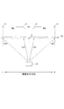
図8は、実施例及び比較例の反射スクリーンの評価方法を説明する図である。
まず、暗室環境下において、図8に示すように、映像源LSから白色光を照射し、画面中央となる点Cを通り画面左右方向に平行な面内において、点Cに対してd1=3m離れた位置であって、点Cを通るスクリーン面の法線方向(正面方向)に対して角度φ=0°,±10°,±20°,±30°,±40°をなす方向から、輝度計(コニカミノルタ社製 LS−110)によって点Cにおける輝度を測定した。そして、測定によって得られた画面左右方向の輝度分布から、画面左右方向における1/2角αHを得た。
なお、正面輝度は、上記測定において、画面左右方向の角度φ=0°で測定された輝度から算出されたピークゲインを用いて評価した。
The image light (white display) is actually projected from the image source LS to the reflective screens of these examples and comparative examples, and the front luminance, the luminance distribution in the vertical and horizontal directions of the screen, the contrast, etc. Examined.
FIG. 8 is a diagram illustrating a method for evaluating the reflective screens of Examples and Comparative Examples.
First, in a dark room environment, as shown in FIG. 8, white light is emitted from the image source LS, and d1 = 3 m with respect to the point C in a plane parallel to the horizontal direction of the screen passing through the point C that is the center of the screen. From the direction which is a remote position and forms an angle φ = 0 °, ± 10 °, ± 20 °, ± 30 °, ± 40 ° with respect to the normal direction (front direction) of the screen surface passing through the point C, The luminance at point C was measured with a luminance meter (LS-110 manufactured by Konica Minolta). Then, a half angle αH in the horizontal direction of the screen was obtained from the luminance distribution in the horizontal direction of the screen obtained by the measurement.
The front luminance was evaluated using the peak gain calculated from the luminance measured at the angle φ = 0 ° in the horizontal direction of the screen in the above measurement.
また、コントラストは、明室環境下(点Cでの照度:100lx)における、実施例及び比較例の反射スクリーンの白色表示時の画面中央となる点Cでの輝度(白輝度:W)と、黒色表示時の点Cでの輝度(黒輝度:B)との比である。これらの輝度は、前述の1/2角α等の測定と同様に、点Cに対してd1=3m離れた位置であって、点Cを通るスクリーン面の法線方向(正面方向)となす角度φ=0°となる方向から前述の輝度計により測定した。
以下の表1は、上述の各評価結果を示す表である。
Further, the contrast is the brightness at the point C (white brightness: W) at the center of the screen when the white display of the reflective screen of the example and the comparative example in the bright room environment (illuminance at the point C: 100 lx), This is the ratio with the luminance at point C during black display (black luminance: B). Similar to the measurement of the half angle α and the like described above, these luminances are located at a distance of d1 = 3 m from the point C and are in the normal direction (front direction) of the screen surface passing through the point C. The measurement was performed with the above luminance meter from the direction where the angle φ = 0 °.
Table 1 below is a table showing the evaluation results described above.

コントラストは、白輝度と黒輝度との比W/Bが、80以上の値となるものを良(○)とし、それ以下の値となるものを不可(×)とした。
また、正面輝度は、ピークゲインが0.9以上のものを良(○)とし、0.9未満のものを不可(×)とした。
さらに、視野角に関しては、画面左右方向において、1/2角αH(画面右側及び左側の半値角の絶対値の平均値)が、22°以上を優(◎)とし、20°以上22°未満を良(○)とし、20°未満を不可(×)とした。スクリーンとしては、画面上下方向よりも画面左右方向の視野角が重視されるため、表1では、画面左右方向の1/2角αHを用いて評価している。
Contrast was determined to be good (◯) when the ratio W / B of white luminance to black luminance was 80 or more, and unacceptable (X) when the ratio was less than 80.
In addition, the front luminance with a peak gain of 0.9 or more was evaluated as good (◯), and the luminance below 0.9 was determined as unacceptable (×).
Furthermore, regarding the viewing angle, in the left-right direction of the screen, the 1/2 angle αH (average value of the absolute value of the half-value angle on the right and left sides of the screen) is 22 ° or more (◎), and 20 ° or more and less than 22 °. Was good (◯), and less than 20 ° was not possible (x). Since the viewing angle in the left-right direction of the screen is more important than the up-down direction of the screen, Table 1 is evaluated using the 1/2 angle αH in the left-right direction of the screen.
上記表1に示すように、比較例1,2は、いずれも、正面輝度が低く、コントラストも不十分な値を示し、目視した場合の映像も暗く、コントラストが低かった。これに対して、実施例1,2は、コントラストも正面輝度も十分な値を有しており、明るくコントラストの高い良好な映像が観察された。
また、比較例2及び実施例1,2は、画面左右方向において十分な視野角を有していたが、比較例1は、画面左右方向において視野角が不十分であった。さらに、実施例1,2は、前述の画面左右方向の視野角評価と同様な方法で輝度分布を測定した画面上下方向においても、1/2角が±10°程度であり、十分な視野角を有し、かつ、不要な光の広がりは抑制されていた。
さらに、実施例1は、実施例2と比較して、黒輝度(B)が低く、コントラストW/Bの値が大きく、コントラストが良好な映像が表示され、また、不使用時等の反射スクリーンの品位の点でも優れていた。
以上のことから、実施例1,2の反射スクリーンによれば、十分な視野角を有し、明るく、コントラストも高い良好な映像を表示できる。
As shown in Table 1 above, Comparative Examples 1 and 2 both had low front luminance, an insufficient contrast value, a dark image when viewed, and low contrast. On the other hand, in Examples 1 and 2, both the contrast and the front luminance had sufficient values, and good images with bright and high contrast were observed.
Further, Comparative Example 2 and Examples 1 and 2 had a sufficient viewing angle in the horizontal direction of the screen, but Comparative Example 1 had an insufficient viewing angle in the horizontal direction of the screen. Further, in the first and second embodiments, the 1/2 angle is about ± 10 ° in the vertical direction of the screen in which the luminance distribution is measured by the same method as the evaluation of the viewing angle in the horizontal direction of the screen described above. And the spread of unnecessary light was suppressed.
Furthermore, compared with Example 2, Example 1 has a low black luminance (B), a large contrast W / B value, displays an image with good contrast, and is a reflective screen when not in use. It was also excellent in terms of quality.
From the above, according to the reflective screens of Examples 1 and 2, it is possible to display a good image having a sufficient viewing angle, bright and high contrast.
(変形形態)
以上説明した各実施形態に限定されることなく、種々の変形や変更が可能であって、それらも本発明の範囲内である。
(1)各実施形態において、第1異方性拡散層15及び第2異方性拡散層14は、画面左右方向において、角度範囲A1,角度範囲A2からの入射光を拡散する例を挙げて示したが、これに限らず、第1異方性拡散層15を、法線Hを軸として画面左右方向に対して角度+δ回転させ、第2異方性拡散層14を、法線Hを軸として画面左右方向に対して角度−δ回転させて配置してもよい。このような形態とした場合には、画面上下方向においても第1異方性拡散層15及び第2異方性拡散層14の異方性を有する拡散作用を発揮することができる。
(Deformation)
Without being limited to the embodiments described above, various modifications and changes are possible, and these are also within the scope of the present invention.
(1) In each embodiment, the first
(2)各実施形態において、表面層18は、ハードコート機能、天井への映像光の映り込み低減機能、防眩機能を備える例を示したが、これに限らず、反射防止機能や紫外線吸収機能、防汚機能や帯電防止機能等を適宜選択してさらに付与してもよい。これらの層は、上述の表面層18と着色層17,27との間に別層として設けてもよいし、表面層18上にさらに積層してもよいし、表面層18を形成する樹脂に、上述の機能を有するものを選択して形成してもよい。
(2) In each embodiment, although the
(3)各実施形態において、第1異方性拡散層15、第2異方性拡散層14は、画面左右方向の拡散作用を有する例を示したが、これに限らず、例えば、使用する光源の位置や使用環境、所望する光学特性等に応じて、第1異方性拡散層15、第2異方性拡散層14が、画面上下方向の拡散作用を有する形態としてもよい。
(3) In each embodiment, although the 1st
(4)第2実施形態において、反射スクリーン20は、略平板状である例を示したが、これに限らず、不使用時には巻き取って保管できる巻き取り可能な形態としてもよい。このような形態の場合には、支持板等を設けず、反射スクリーン20の背面側を、光を透過しにくい布製又は樹脂製の遮光幕や耐傷性を向上させる保護層等で被覆する形態とすれば、コントラスト向上や、レンズ層13や反射層12の破損や劣化の防止を図ることができる。
(4) In 2nd Embodiment, although the
(5)各実施形態において、映像源LSは、鉛直方向において反射スクリーン10,20より下方に位置し、映像光Lが反射スクリーン10,20の下方から斜めに投射される例を示したが、これに限らず、例えば、映像源LSが、鉛直方向において反射スクリーン10,20より上方に位置し、映像光Lが反射スクリーン10,20の上方から斜めに投射される形態としてもよい。このとき、反射スクリーン10,20は、図2や図3等に示すレンズ層13の上下方向を反転させ、サーキュラーフレネルレンズの光学的中心(フレネルセンター)である点Fが反射スクリーン10,20の上方に位置する形態とすればよい。
(5) In each embodiment, the video source LS is positioned below the
(6)各実施形態において、単位レンズ131は、図2等に示す断面形状が略三角形形状である例を示したが、これに限らず、例えば、略台形形状であり、レンズ面と非レンズ面とが、スクリーン面に平行な頂面を挟んで対向する形態としてもよい。このとき、頂面は、映像光の反射に寄与しない領域に形成されることが好ましい。この頂面上には、光吸収層を形成してもよいし、反射層を形成してもよい。
また、本実施形態において、単位レンズ131は、図2等に示す断面において、レンズ面132及び非レンズ面133が直線状となる例を示したが、これに限らず、この断面において、例えば、レンズ面132や非レンズ面133の一部が曲線状となっていてもよいし、レンズ面132及び非レンズ面133は、少なくとも一方の面が、複数の面から構成される形態としてもよい。
(6) In each embodiment, the
In the present embodiment, the
なお、本実施形態及び変形形態は、適宜組み合わせて用いることもできるが、詳細な説明は省略する。また、本発明は以上説明した各実施形態によって限定されることはない。 In addition, although this embodiment and modification can also be used in combination as appropriate, detailed description is abbreviate | omitted. Further, the present invention is not limited by the embodiments described above.
1 映像表示システム
10,20 反射スクリーン
11 光吸収層
12,22 反射層
13 レンズ層
14 第2異方性拡散層
15 第1異方性拡散層
16 等方性拡散層
17,27 着色層
18 表面層
DESCRIPTION OF
Claims (6)
レンズ面と非レンズ面とを有し背面側に凸となる単位レンズが複数配列されたフレネルレンズ形状を背面側に有するレンズ層と、
少なくとも前記単位レンズの前記レンズ面に形成され、光を反射する反射層と、
該反射スクリーンの厚み方向において前記レンズ層よりも映像源側に配置され、光の入射角に依らず光を等方的に拡散して透過する作用を有する等方性拡散層と、
該反射スクリーンの厚み方向において前記レンズ層よりも映像源側に配置され、スクリーン面に平行な第1の方向及び前記スクリーン面の法線方向に平行な断面において第1の角度範囲内の入射角で入射した光を拡散して透過し、前記第1の角度範囲外の入射角で入射した光を拡散せずに透過する作用を有する第1異方性拡散層と、
該反射スクリーンの厚み方向において前記レンズ層よりも映像源側に配置され、前記第1の方向及び前記スクリーン面の法線方向に平行な断面において、前記スクリーン面の法線方向を軸として前記第1の角度範囲と対称な第2の角度範囲内の入射角で入射した光を拡散して透過し、前記第2の角度範囲外の入射角で入射した光を拡散せずに透過する作用を有する第2異方性拡散層と、
を備える反射スクリーン。 A reflection screen that reflects the image light projected from the image source and displays the image light so as to be observable;
A lens layer having a lens surface and a non-lens surface and having a Fresnel lens shape on the back side in which a plurality of unit lenses convex on the back side are arranged;
A reflection layer that is formed on at least the lens surface of the unit lens and reflects light;
An isotropic diffusion layer that is disposed closer to the image source than the lens layer in the thickness direction of the reflective screen and has an action of diffusing and transmitting light isotropically regardless of the incident angle of the light;
An incident angle within a first angle range in a first direction parallel to the screen surface and a cross section parallel to the normal direction of the screen surface, which is disposed closer to the image source than the lens layer in the thickness direction of the reflective screen. A first anisotropic diffusion layer having a function of diffusing and transmitting the incident light at, and transmitting the light incident at an incident angle outside the first angle range without diffusing;
In the thickness direction of the reflective screen, it is disposed closer to the image source side than the lens layer, and in the cross section parallel to the first direction and the normal direction of the screen surface, the first direction and the normal direction of the screen surface as an axis. The function of diffusing and transmitting light incident at an incident angle within a second angle range symmetric to the angle range of 1 and transmitting light incident at an incident angle outside the second angle range without diffusing. A second anisotropic diffusion layer having
Reflective screen with.
前記第1の方向は、該反射スクリーンの画面左右方向であること、
を特徴とする反射スクリーン。 The reflective screen according to claim 1.
The first direction is a screen left-right direction of the reflective screen;
Reflective screen featuring.
該反射スクリーンの厚み方向において前記レンズ層よりも映像源側に配置され、該反射スクリーンの剛性を維持し、該反射スクリーンの他の層よりも厚さが厚い基板層を備えること、
を特徴とする反射スクリーン。 The reflective screen according to claim 1 or 2,
A substrate layer that is disposed closer to the image source than the lens layer in the thickness direction of the reflective screen, maintains the rigidity of the reflective screen, and is thicker than the other layers of the reflective screen;
Reflective screen featuring.
前記基板層は、所定の透過率となるように着色されていること、
を特徴とする反射スクリーン。 The reflective screen according to claim 3,
The substrate layer is colored so as to have a predetermined transmittance,
Reflective screen featuring.
少なくとも前記非レンズ面には、光を吸収する光吸収層が形成されていること、
を特徴とする反射スクリーン。 The reflective screen according to any one of claims 1 to 4, wherein:
A light absorption layer for absorbing light is formed at least on the non-lens surface;
Reflective screen featuring.
前記反射スクリーンに映像光を投射する映像源と、
を備える映像表示システム。 A reflective screen according to any one of claims 1 to 5,
An image source for projecting image light onto the reflective screen;
A video display system comprising:
Priority Applications (1)
| Application Number | Priority Date | Filing Date | Title |
|---|---|---|---|
| JP2012197878A JP5949355B2 (en) | 2012-09-07 | 2012-09-07 | Reflective screen, video display system |
Applications Claiming Priority (1)
| Application Number | Priority Date | Filing Date | Title |
|---|---|---|---|
| JP2012197878A JP5949355B2 (en) | 2012-09-07 | 2012-09-07 | Reflective screen, video display system |
Publications (2)
| Publication Number | Publication Date |
|---|---|
| JP2014052554A true JP2014052554A (en) | 2014-03-20 |
| JP5949355B2 JP5949355B2 (en) | 2016-07-06 |
Family
ID=50611070
Family Applications (1)
| Application Number | Title | Priority Date | Filing Date |
|---|---|---|---|
| JP2012197878A Active JP5949355B2 (en) | 2012-09-07 | 2012-09-07 | Reflective screen, video display system |
Country Status (1)
| Country | Link |
|---|---|
| JP (1) | JP5949355B2 (en) |
Cited By (4)
| Publication number | Priority date | Publication date | Assignee | Title |
|---|---|---|---|---|
| JP2016085306A (en) * | 2014-10-24 | 2016-05-19 | 大日本印刷株式会社 | Reflection screen and picture display system |
| JP2017173440A (en) * | 2016-03-22 | 2017-09-28 | 大日本印刷株式会社 | Reflection screen and video display system |
| JP2020064319A (en) * | 2019-12-26 | 2020-04-23 | 大日本印刷株式会社 | Reflective screen and image display device |
| JP2021063860A (en) * | 2019-10-10 | 2021-04-22 | 大日本印刷株式会社 | Reflective screen and image display device |
Citations (4)
| Publication number | Priority date | Publication date | Assignee | Title |
|---|---|---|---|---|
| JP2002540445A (en) * | 1999-03-19 | 2002-11-26 | スリーエム イノベイティブ プロパティズ カンパニー | Reflection projection screen and projection system |
| JP2005326824A (en) * | 2004-04-09 | 2005-11-24 | Seiko Instruments Inc | Screen and image projection system using same |
| JP2006084769A (en) * | 2004-09-16 | 2006-03-30 | Sumitomo Chemical Co Ltd | Light control film laminate and projection screen using the same |
| JP2012042599A (en) * | 2010-08-17 | 2012-03-01 | Nippon Telegr & Teleph Corp <Ntt> | Reflective front screen having recursive property and reflective screen for stereoscopic display |
-
2012
- 2012-09-07 JP JP2012197878A patent/JP5949355B2/en active Active
Patent Citations (4)
| Publication number | Priority date | Publication date | Assignee | Title |
|---|---|---|---|---|
| JP2002540445A (en) * | 1999-03-19 | 2002-11-26 | スリーエム イノベイティブ プロパティズ カンパニー | Reflection projection screen and projection system |
| JP2005326824A (en) * | 2004-04-09 | 2005-11-24 | Seiko Instruments Inc | Screen and image projection system using same |
| JP2006084769A (en) * | 2004-09-16 | 2006-03-30 | Sumitomo Chemical Co Ltd | Light control film laminate and projection screen using the same |
| JP2012042599A (en) * | 2010-08-17 | 2012-03-01 | Nippon Telegr & Teleph Corp <Ntt> | Reflective front screen having recursive property and reflective screen for stereoscopic display |
Cited By (5)
| Publication number | Priority date | Publication date | Assignee | Title |
|---|---|---|---|---|
| JP2016085306A (en) * | 2014-10-24 | 2016-05-19 | 大日本印刷株式会社 | Reflection screen and picture display system |
| JP2017173440A (en) * | 2016-03-22 | 2017-09-28 | 大日本印刷株式会社 | Reflection screen and video display system |
| JP2021063860A (en) * | 2019-10-10 | 2021-04-22 | 大日本印刷株式会社 | Reflective screen and image display device |
| JP7314757B2 (en) | 2019-10-10 | 2023-07-26 | 大日本印刷株式会社 | Reflective screen, image display device |
| JP2020064319A (en) * | 2019-12-26 | 2020-04-23 | 大日本印刷株式会社 | Reflective screen and image display device |
Also Published As
| Publication number | Publication date |
|---|---|
| JP5949355B2 (en) | 2016-07-06 |
Similar Documents
| Publication | Publication Date | Title |
|---|---|---|
| JP2014010404A (en) | Reflection screen, and video display system | |
| JP2013171114A (en) | Reflective screen and video display system | |
| CN109917613B (en) | Reflection type screen and image display system | |
| JP2012226047A (en) | Reflection screen, and manufacturing method of reflection screen | |
| JP5939116B2 (en) | Reflective screen, video display system | |
| JP2012226103A (en) | Reflection screen and image display system | |
| JP2016109803A (en) | Reflective screen and image display system | |
| JP5949355B2 (en) | Reflective screen, video display system | |
| JP6272013B2 (en) | Reflective screen, video display system | |
| JP5949356B2 (en) | Reflective screen, 3D image display system | |
| JP2014077883A (en) | Reflection screen, video display system | |
| JP2014142429A (en) | Reflective screen, front projection display device, and multi-screen display device | |
| JP5998769B2 (en) | Reflective screen, video display system | |
| JP2016151649A (en) | Reflection screen and video display system | |
| JP2016114628A (en) | Reflective screen and image display system | |
| JP2015014649A (en) | Reflective screen and image display system | |
| JP2015004821A (en) | Reflection type screen, and video display system | |
| JP5974789B2 (en) | Reflective screen, video display system | |
| JP5780112B2 (en) | Reflective screen, video display system | |
| JP6507563B2 (en) | Reflective screen, image display system | |
| JP2021096297A (en) | Reflection type screen and video display device | |
| JP7521364B2 (en) | Video display device | |
| JP7201115B1 (en) | Reflective screen, image display device | |
| JP2015069110A (en) | Reflective screen and image display system | |
| JP2014071388A (en) | Screen, image display system, and method for manufacturing screen |
Legal Events
| Date | Code | Title | Description |
|---|---|---|---|
| A621 | Written request for application examination |
Free format text: JAPANESE INTERMEDIATE CODE: A621 Effective date: 20150727 |
|
| A977 | Report on retrieval |
Free format text: JAPANESE INTERMEDIATE CODE: A971007 Effective date: 20160422 |
|
| TRDD | Decision of grant or rejection written | ||
| A01 | Written decision to grant a patent or to grant a registration (utility model) |
Free format text: JAPANESE INTERMEDIATE CODE: A01 Effective date: 20160510 |
|
| A61 | First payment of annual fees (during grant procedure) |
Free format text: JAPANESE INTERMEDIATE CODE: A61 Effective date: 20160523 |
|
| R150 | Certificate of patent or registration of utility model |
Ref document number: 5949355 Country of ref document: JP Free format text: JAPANESE INTERMEDIATE CODE: R150 |
|
| RD04 | Notification of resignation of power of attorney |
Free format text: JAPANESE INTERMEDIATE CODE: R3D04 |