JP2013507779A - CVD reactor with substrate holder placed on a gas cushion consisting of multiple zones - Google Patents
CVD reactor with substrate holder placed on a gas cushion consisting of multiple zones Download PDFInfo
- Publication number
- JP2013507779A JP2013507779A JP2012533582A JP2012533582A JP2013507779A JP 2013507779 A JP2013507779 A JP 2013507779A JP 2012533582 A JP2012533582 A JP 2012533582A JP 2012533582 A JP2012533582 A JP 2012533582A JP 2013507779 A JP2013507779 A JP 2013507779A
- Authority
- JP
- Japan
- Prior art keywords
- gas
- substrate holder
- zones
- cvd reactor
- substrate
- Prior art date
- Legal status (The legal status is an assumption and is not a legal conclusion. Google has not performed a legal analysis and makes no representation as to the accuracy of the status listed.)
- Granted
Links
Images


Classifications
-
- C—CHEMISTRY; METALLURGY
- C23—COATING METALLIC MATERIAL; COATING MATERIAL WITH METALLIC MATERIAL; CHEMICAL SURFACE TREATMENT; DIFFUSION TREATMENT OF METALLIC MATERIAL; COATING BY VACUUM EVAPORATION, BY SPUTTERING, BY ION IMPLANTATION OR BY CHEMICAL VAPOUR DEPOSITION, IN GENERAL; INHIBITING CORROSION OF METALLIC MATERIAL OR INCRUSTATION IN GENERAL
- C23C—COATING METALLIC MATERIAL; COATING MATERIAL WITH METALLIC MATERIAL; SURFACE TREATMENT OF METALLIC MATERIAL BY DIFFUSION INTO THE SURFACE, BY CHEMICAL CONVERSION OR SUBSTITUTION; COATING BY VACUUM EVAPORATION, BY SPUTTERING, BY ION IMPLANTATION OR BY CHEMICAL VAPOUR DEPOSITION, IN GENERAL
- C23C16/00—Chemical coating by decomposition of gaseous compounds, without leaving reaction products of surface material in the coating, i.e. chemical vapour deposition [CVD] processes
- C23C16/44—Chemical coating by decomposition of gaseous compounds, without leaving reaction products of surface material in the coating, i.e. chemical vapour deposition [CVD] processes characterised by the method of coating
- C23C16/458—Chemical coating by decomposition of gaseous compounds, without leaving reaction products of surface material in the coating, i.e. chemical vapour deposition [CVD] processes characterised by the method of coating characterised by the method used for supporting substrates in the reaction chamber
- C23C16/4582—Rigid and flat substrates, e.g. plates or discs
- C23C16/4583—Rigid and flat substrates, e.g. plates or discs the substrate being supported substantially horizontally
- C23C16/4584—Rigid and flat substrates, e.g. plates or discs the substrate being supported substantially horizontally the substrate being rotated
-
- C—CHEMISTRY; METALLURGY
- C23—COATING METALLIC MATERIAL; COATING MATERIAL WITH METALLIC MATERIAL; CHEMICAL SURFACE TREATMENT; DIFFUSION TREATMENT OF METALLIC MATERIAL; COATING BY VACUUM EVAPORATION, BY SPUTTERING, BY ION IMPLANTATION OR BY CHEMICAL VAPOUR DEPOSITION, IN GENERAL; INHIBITING CORROSION OF METALLIC MATERIAL OR INCRUSTATION IN GENERAL
- C23C—COATING METALLIC MATERIAL; COATING MATERIAL WITH METALLIC MATERIAL; SURFACE TREATMENT OF METALLIC MATERIAL BY DIFFUSION INTO THE SURFACE, BY CHEMICAL CONVERSION OR SUBSTITUTION; COATING BY VACUUM EVAPORATION, BY SPUTTERING, BY ION IMPLANTATION OR BY CHEMICAL VAPOUR DEPOSITION, IN GENERAL
- C23C16/00—Chemical coating by decomposition of gaseous compounds, without leaving reaction products of surface material in the coating, i.e. chemical vapour deposition [CVD] processes
- C23C16/44—Chemical coating by decomposition of gaseous compounds, without leaving reaction products of surface material in the coating, i.e. chemical vapour deposition [CVD] processes characterised by the method of coating
- C23C16/458—Chemical coating by decomposition of gaseous compounds, without leaving reaction products of surface material in the coating, i.e. chemical vapour deposition [CVD] processes characterised by the method of coating characterised by the method used for supporting substrates in the reaction chamber
- C23C16/4582—Rigid and flat substrates, e.g. plates or discs
- C23C16/4583—Rigid and flat substrates, e.g. plates or discs the substrate being supported substantially horizontally
- C23C16/4586—Elements in the interior of the support, e.g. electrodes, heating or cooling devices
-
- C—CHEMISTRY; METALLURGY
- C23—COATING METALLIC MATERIAL; COATING MATERIAL WITH METALLIC MATERIAL; CHEMICAL SURFACE TREATMENT; DIFFUSION TREATMENT OF METALLIC MATERIAL; COATING BY VACUUM EVAPORATION, BY SPUTTERING, BY ION IMPLANTATION OR BY CHEMICAL VAPOUR DEPOSITION, IN GENERAL; INHIBITING CORROSION OF METALLIC MATERIAL OR INCRUSTATION IN GENERAL
- C23C—COATING METALLIC MATERIAL; COATING MATERIAL WITH METALLIC MATERIAL; SURFACE TREATMENT OF METALLIC MATERIAL BY DIFFUSION INTO THE SURFACE, BY CHEMICAL CONVERSION OR SUBSTITUTION; COATING BY VACUUM EVAPORATION, BY SPUTTERING, BY ION IMPLANTATION OR BY CHEMICAL VAPOUR DEPOSITION, IN GENERAL
- C23C16/00—Chemical coating by decomposition of gaseous compounds, without leaving reaction products of surface material in the coating, i.e. chemical vapour deposition [CVD] processes
- C23C16/44—Chemical coating by decomposition of gaseous compounds, without leaving reaction products of surface material in the coating, i.e. chemical vapour deposition [CVD] processes characterised by the method of coating
- C23C16/46—Chemical coating by decomposition of gaseous compounds, without leaving reaction products of surface material in the coating, i.e. chemical vapour deposition [CVD] processes characterised by the method of coating characterised by the method used for heating the substrate
-
- C—CHEMISTRY; METALLURGY
- C23—COATING METALLIC MATERIAL; COATING MATERIAL WITH METALLIC MATERIAL; CHEMICAL SURFACE TREATMENT; DIFFUSION TREATMENT OF METALLIC MATERIAL; COATING BY VACUUM EVAPORATION, BY SPUTTERING, BY ION IMPLANTATION OR BY CHEMICAL VAPOUR DEPOSITION, IN GENERAL; INHIBITING CORROSION OF METALLIC MATERIAL OR INCRUSTATION IN GENERAL
- C23C—COATING METALLIC MATERIAL; COATING MATERIAL WITH METALLIC MATERIAL; SURFACE TREATMENT OF METALLIC MATERIAL BY DIFFUSION INTO THE SURFACE, BY CHEMICAL CONVERSION OR SUBSTITUTION; COATING BY VACUUM EVAPORATION, BY SPUTTERING, BY ION IMPLANTATION OR BY CHEMICAL VAPOUR DEPOSITION, IN GENERAL
- C23C16/00—Chemical coating by decomposition of gaseous compounds, without leaving reaction products of surface material in the coating, i.e. chemical vapour deposition [CVD] processes
- C23C16/44—Chemical coating by decomposition of gaseous compounds, without leaving reaction products of surface material in the coating, i.e. chemical vapour deposition [CVD] processes characterised by the method of coating
- C23C16/48—Chemical coating by decomposition of gaseous compounds, without leaving reaction products of surface material in the coating, i.e. chemical vapour deposition [CVD] processes characterised by the method of coating by irradiation, e.g. photolysis, radiolysis, particle radiation
- C23C16/481—Chemical coating by decomposition of gaseous compounds, without leaving reaction products of surface material in the coating, i.e. chemical vapour deposition [CVD] processes characterised by the method of coating by irradiation, e.g. photolysis, radiolysis, particle radiation by radiant heating of the substrate
-
- H10P14/24—
-
- H10P14/6339—
Landscapes
- Chemical & Material Sciences (AREA)
- General Chemical & Material Sciences (AREA)
- Chemical Kinetics & Catalysis (AREA)
- Engineering & Computer Science (AREA)
- Materials Engineering (AREA)
- Mechanical Engineering (AREA)
- Metallurgy (AREA)
- Organic Chemistry (AREA)
- Health & Medical Sciences (AREA)
- Toxicology (AREA)
- Chemical Vapour Deposition (AREA)
Abstract
【課題】凸状または凹状の温度プロファイルを基板ホルダの表面に生じさせる。
【解決手段】基板ホルダキャリア(1)は支持面(4‘)を備え、複数のガス供給ライン(7、8)が支持面(4‘)に開く。基板ホルダキャリア(1)の上には基板ホルダ(2)が配置されており、その裏面は支持面(4‘)に面し、支持面(4‘)と基板ホルダ(2)の裏面との間の空間にガス供給ライン(7、8)を通って供給されるガスが、基板ホルダ(2)を支持するガスクッション(19)を形成する。ガスクッション(19)は、ガス供給ライン(7、8)を通ってガスを供給される複数のゾーン(A、C)を備える。ゾーン(A、C)は、それらの間でガスの交換を防ぐ手段によってお互いから分離されている。ゾーン(A、C)はガス排出ライン(13、14)を通ってガスを排出することができる。異なる熱伝導特性を持つガスがそれらのゾーン(A、C)に供給される。
【選択図】図4
A convex or concave temperature profile is generated on a surface of a substrate holder.
A substrate holder carrier (1) includes a support surface (4 '), and a plurality of gas supply lines (7, 8) open to the support surface (4'). The substrate holder (2) is arranged on the substrate holder carrier (1), the back surface thereof faces the support surface (4 ′), and the support surface (4 ′) and the back surface of the substrate holder (2) are arranged. The gas supplied through the gas supply lines (7, 8) to the space between them forms a gas cushion (19) that supports the substrate holder (2). The gas cushion (19) comprises a plurality of zones (A, C) that are supplied with gas through gas supply lines (7, 8). Zones (A, C) are separated from each other by means that prevent exchange of gases between them. Zones (A, C) can discharge gas through gas discharge lines (13, 14). Gases with different heat transfer characteristics are supplied to those zones (A, C).
[Selection] Figure 4
Description
本発明は、動的ガスクッション上で基板ホルダキャリアによって運ばれる少なくとも1つの基板ホルダを持つCVD反応炉に関する。その基板ホルダはヒーターによって裏面から加熱可能である。 The present invention relates to a CVD reactor having at least one substrate holder carried by a substrate holder carrier on a dynamic gas cushion. The substrate holder can be heated from the back by a heater.
また、本発明は、下から加熱され、動的なガスクッションで運ばれ、特に回転駆動される基板ホルダの表面温度の制御方法に関する。 The present invention also relates to a method for controlling the surface temperature of a substrate holder that is heated from below, carried by a dynamic gas cushion, and driven to rotate.
特許文献1は、反応炉ハウジング、その反応炉ハウジングの中に配置されたプロセスチャンバー、およびそのプロセスチャンバーの底を形成する基板ホルダキャリアを持ったCVD反応炉を開示する。これは中心の周りにリング状に配置された多数の円形の支持ポケットを持ち、その中にガス供給ラインが開く。基板ホルダキャリアは支持ポケットの中に包み込まれ、各基板ホルダキャリアは基板を運ぶ。基板は、III-V属半導体層でコーティングされる。これのために必要とされる出発物質は、ガス状であり、例えば有機金属成分と水素化物から成る。出発物質は、ガス混合システムでキャリアガスと混合される。ガス混合物は別々のチャンネルを通ってガス注入エレメントに着き、それらのガスはプロセスチャンバーに導入される。プロセスチャンバーは下から加熱される。これはRFヒーターまたは抵抗ヒーターによって生じさせられる。グラファイトから成る基板ホルダキャリアを通ってプロセスチャンバーに面する基板ホルダの表面に熱伝導によって熱が伝わる。これのために基板に運ばれる熱は、動的ガスクッションによって形成されるギャップのバリアを越えなければならない。動的ガスクッションの上に基板ホルダが置かれ、動的ガスクッションによって基板ホルダは回転駆動される。プロセスチャンバーの中に導入されたガス、例えばTMGaまたはTMInまたはTMAlの他にASH3、NH3またはPH3もまた熱分解される。分解反応は、プロセスチャンバーの床の熱い表面および下から加熱される基板の表面で主として起こる。成長率および層の組成または結晶の質は、かなりの程度それぞれの局部的な表面温度によって決まる。最高の可能な横方向の温度の均一性を得るために、基板ホルダキャリアから基板ホルダへの熱の流れが局部的に異なるように、支持ポケットの底と基板ホルダの裏面との間のギャップの高さが変わるように構成することが特許文献1で提案される。ギャップの高さの半径方向の変化の適切な選択によって、凹状または凸状の温度プロファイルを達成することができ、または平らな温度プロファイルさえ達成することができる。
U.S. Patent No. 6,057,051 discloses a CVD reactor having a reactor housing, a process chamber disposed within the reactor housing, and a substrate holder carrier that forms the bottom of the process chamber. It has a number of circular support pockets arranged in a ring around the center, in which the gas supply line opens. The substrate holder carrier is encased in a support pocket, and each substrate holder carrier carries a substrate. The substrate is coated with a III-V semiconductor layer. The starting materials required for this are gaseous and consist, for example, of organometallic components and hydrides. The starting material is mixed with the carrier gas in a gas mixing system. The gas mixture arrives at the gas injection element through separate channels and the gases are introduced into the process chamber. The process chamber is heated from below. This can be caused by an RF heater or a resistance heater. Heat is transferred by heat conduction through the substrate holder carrier made of graphite to the surface of the substrate holder facing the process chamber. For this purpose, the heat transferred to the substrate must cross the gap barrier formed by the dynamic gas cushion. A substrate holder is placed on the dynamic gas cushion, and the substrate holder is rotationally driven by the dynamic gas cushion. In addition to gases introduced into the process chamber, such as TMGa or TMIn or TMAl, A S H 3 , NH 3 or PH 3 are also thermally decomposed. The decomposition reaction occurs mainly on the hot surface of the process chamber floor and the surface of the substrate heated from below. Growth rate and layer composition or crystal quality are determined to a large extent by the respective local surface temperature. In order to obtain the highest possible lateral temperature uniformity, the gap between the bottom of the support pocket and the back of the substrate holder should be such that the heat flow from the substrate holder carrier to the substrate holder is locally different.
特許文献2は同様に基板ホルダキャリアを持ったCVD反応炉に関する。プロセスチャンバーに面する基板ホルダキャリアの表面に多数の基板ホルダが配置されており、各基板ホルダは動的回転ベアリングの上に置かれている。ここで、各動的回転ベアリングは個別のガス供給に接続されており、それでガスの質は個別に変えられることができる。
特許文献3は、CVD反応炉の中の基板の表面温度の制御方法に関する。平均温度は、異なるポイントで測定された表面温度から定められる。基板温度はガスクッションの高さによって調節されることができる。また、これは各基板ホルダに対して個別であることができる。
特許文献4から知られる基板処理装置では、基板は基板ホルダの表面に置かれる。基板ホルダの支持面は、お互いに関して同心円状に位置する複数の浅い溝を与える。それらの溝の中にガス供給ラインが開き、それらの溝からガス排出ラインが出る。それらの溝は圧力可変の冷却ガスによって作用される。
In the substrate processing apparatus known from
特許文献5から知られるCVD反応炉では、基板ホルダキャリアが3つの支持ピンを運び、ディスク状の基板ホルダが各支持ピンの周りに回転可能に取り付けられ、ガスクッションの上に回転可能に置かれる。 In the CVD reactor known from US Pat. No. 6,057,049, a substrate holder carrier carries three support pins, and a disk-like substrate holder is rotatably mounted around each support pin and placed rotatably on a gas cushion. .
特許文献6は、ガスを排出することができる多数の開口を持つワークピースキャリアを開示する。そのガスはキャリアとワークピースの間で熱の移動を達成する動的ガス層を形成する。
特許文献7は、基板をガスクッションの上で支持することができるベアリングシェルを持つ基板ホルダを備えたCVD反応炉を開示する。多数のガス供給ラインが支持ポケットの底に開く。
特許文献8は、お互いから離れた2つのガス供給ラインと、支持ポケットの底に配置されており、それらのガス供給ラインを通って供給されるガスチャンネルとを備えた加熱可能な基板ホルダを開示する。
特許文献9は、基板がガスクッションの上に置かれることができる基板ホルダを備えたCVD反応炉を開示する。 U.S. Patent No. 6,057,031 discloses a CVD reactor with a substrate holder that allows a substrate to be placed on a gas cushion.
本発明は、1インチ以上の直径を持つ基板のための基板ホルダの場合には、表面に直角の温度勾配のために基板にゆがみが生じるという問題に取り組む。基板が基板ホルダの上で中心領域にのみまたは半径方向に外側の領域にのみ置かれるので、この基板のへこみまたは湾曲は横方向の温度勾配に導く。 The present invention addresses the problem that in the case of a substrate holder for a substrate having a diameter of 1 inch or more, the substrate is distorted due to a temperature gradient perpendicular to the surface. Since the substrate is placed on the substrate holder only in the central region or only in the radially outer region, this dent or curvature of the substrate leads to a lateral temperature gradient.
この結果として、基板ホルダから基板への熱の輸送が一様ではなくなる。熱の輸送におけるこの不均等性を相殺するために、対応する凹状または凸状の温度プロファイルを基板ホルダの表面に生じさせる。 As a result, the heat transfer from the substrate holder to the substrate is not uniform. In order to offset this non-uniformity in heat transport, a corresponding concave or convex temperature profile is created on the surface of the substrate holder.
凸状または凹状の温度プロファイルを基板ホルダの表面に生じさせることができる手段を提供することが本発明の目的である。 It is an object of the present invention to provide a means by which a convex or concave temperature profile can be generated on the surface of the substrate holder.
この目的は、請求項に記載された本発明によって達成される。 This object is achieved by the invention as described in the claims.
請求項1は、基板ホルダの裏面との間のガスクッションが個別のガス供給ラインによって供給されることができる複数のゾーンを持つことを最初に提案する。それらのゾーンは望ましくは基板ホルダの回転軸の周りに同心円状に置かれる。最も単純なケースでは、ガスクッションは2つのゾーン、中心ゾーンと外側のゾーンから成る。けれどもまた、複数のゾーンが中心のゾーンを囲むことができる。隣接したゾーンとの間のガスの交換が削減されるように、個々のゾーンはお互いから分離される。これのために適切な手段がゾーンの間に与えられる。望ましくは、個々のゾーンは拡散障壁によってお互いから分離される。ゾーンの同心の配置では、拡散障壁は、リング状であり、ゾーンに供給されるガスのかなりの量が隣接するゾーンに入るのを防ぐ。拡散障壁は、削減された高さの中間のゾーン、ラビリンスシールまたはパージされた中間のゾーンであることができる。
重要なことは、拡散障壁によってお互いに隣接する2つのゾーンの間のガスの交換が最小になることである。この種のガス交換の原因は実質的に拡散であり、それは例えば拡散障壁の半径方向の長さとその横断面によって決まる。従って、拡散障壁の横断面が最小化され、拡散障壁の長さ、特に拡散障壁の半径方向の長さが最大化されることが有利である。お互いに隣接する2つのゾーンの間におけるさらなるガスの移動のメカニズムは、2つのゾーンの間の圧力差に帰せられる対流または流れである。この種の流れを避けるために、同じガス圧力がお互いに隣接するゾーンに広がることが有利である。個々のゾーンに導入されるガスは、ガス混合システムで準備される。これらのガスは、お互いに非常に異なる熱伝導特性を持つ。特に一方で窒素および他方で水素が使われ、または一方でアルゴンおよび他方で水素が使われ、または一方で窒素および他方でヘリウムが使われ、同様に一方でアルゴンおよび他方でヘリウムが使われる。最も単純なケースでは、いずれの場合にもガスがゾーンの一つに導入され、最初のガスと非常に異なる熱伝導特性を持つ他のガスが他のゾーンに導入される。そのとき、2つのガスギャップは異なる熱輸送特性を持つ。このように、熱の輸送はガスギャップによって局部的に影響を及ぼされることができる。けれども望ましくは、異なる熱伝導度を持つ少なくとも2つのガスの混合物が個々のゾーンに導入される。ガスキャップを通る熱の輸送は、2つのガスの混合比によって調節されることができる。例えば、中心のゾーンに導入されるガス混合物が外側のゾーンに導入されるガス混合物よりも大きな熱伝導度を持つならば、基板ホルダの表面の中心は周辺よりももっと強く加熱され、それで周辺は中心よりも低い温度を持つ。他方、外側のゾーンに導入されるガス混合物よりも小さな熱伝導度を持つガス混合物が中心に導入されるとき、周辺は中心よりももっと強く加熱される。そのとき、中心の表面は外側の領域よりも冷たい。 Importantly, the diffusion barrier minimizes gas exchange between two zones adjacent to each other. The cause of this type of gas exchange is substantially diffusion, which is determined, for example, by the radial length of the diffusion barrier and its cross-section. It is therefore advantageous that the cross section of the diffusion barrier is minimized and the length of the diffusion barrier, in particular the radial length of the diffusion barrier, is maximized. The mechanism of further gas movement between two zones adjacent to each other is convection or flow attributed to the pressure difference between the two zones. In order to avoid this kind of flow, it is advantageous for the same gas pressure to spread over adjacent zones. The gas introduced into the individual zones is prepared with a gas mixing system. These gases have very different heat transfer properties. In particular, nitrogen is used on the one hand and hydrogen on the other hand, or argon on the other hand and hydrogen on the other hand, or nitrogen on the other hand and helium on the other hand, as well as argon on the one hand and helium on the other hand. In the simplest case, in each case gas is introduced into one of the zones and other gases with very different heat transfer properties from the first gas are introduced into the other zones. The two gas gaps then have different heat transport properties. In this way, heat transport can be influenced locally by the gas gap. Desirably, however, a mixture of at least two gases having different thermal conductivities is introduced into the individual zones. The transport of heat through the gas cap can be adjusted by the mixing ratio of the two gases. For example, if the gas mixture introduced into the central zone has a greater thermal conductivity than the gas mixture introduced into the outer zone, the center of the surface of the substrate holder is heated more strongly than the periphery, so that the periphery is Has a lower temperature than the center. On the other hand, when a gas mixture having a lower thermal conductivity than the gas mixture introduced into the outer zone is introduced into the center, the periphery is heated more strongly than the center. The central surface is then cooler than the outer area.
熱は基板ホルダキャリアの下にあるヒーターによって生成され、基板ホルダキャリアを加熱する。基板ホルダキャリアまたは基板ホルダの上面の上に、縦方向にプロセスガスが流れるプロセスチャンバーがある。先行技術において原理上は知られているように、プロセスガスは望ましくはプロセスチャンバーの中心に位置するガス注入エレメントを通ってプロセスチャンバーに導入される。プロセスガスは初めに示された有機金属成分と初めに示された水素化物を持つことができる。プロセスチャンバーはガス排出エレメントによって囲まれ、ガス排出エレメントによって分解生成物とキャリアガスが排出される。数ミリバールと大気圧の間の範囲にプロセスチャンバーの中の全圧を設定することができるように、ガス排出エレメントは通常真空ポンプに接続される。 Heat is generated by a heater under the substrate holder carrier to heat the substrate holder carrier. Above the upper surface of the substrate holder carrier or substrate holder is a process chamber through which process gas flows in the vertical direction. As is known in principle in the prior art, the process gas is preferably introduced into the process chamber through a gas injection element located in the center of the process chamber. The process gas can have an organometallic component initially indicated and a hydride initially indicated. The process chamber is surrounded by a gas discharge element, and the decomposition product and carrier gas are discharged by the gas discharge element. The gas discharge element is usually connected to a vacuum pump so that the total pressure in the process chamber can be set to a range between a few millibars and atmospheric pressure.
望ましくは、上述した拡散障壁は基板ホルダキャリアの支持面の環状突起によって形成される。このように、横断面は縮小され、そこを通ってガスの交換が2つのゾーンの間で起こることができる。基板ホルダが包み込まれるポケットの底によって
支持面が形成されることができる。けれどもまた、溝に挿入されるグラファイトまたは金属のボディによってリングが形成されることができる。基板ホルダの裏面は環状の溝を持ち、溝の中に環状の隆起、必要に応じて挿入リングが係合することができる。この溝はリングの幅よりも大きな壁の間隔を持ち、それでラビリンスシールのように何度も方向を変える密封ギャップが形成される。けれどもその一方で基板ホルダの裏面およびポケットの底と関連付けられる溝にリングを固定して接続することが可能である。
Desirably, the diffusion barrier described above is formed by an annular protrusion on the support surface of the substrate holder carrier. In this way, the cross section is reduced through which gas exchange can take place between the two zones. A support surface can be formed by the bottom of the pocket in which the substrate holder is encased. But also the ring can be formed by a graphite or metal body inserted into the groove. The back surface of the substrate holder has an annular groove, in which an annular ridge can be engaged, and an insertion ring can be engaged if necessary. This groove has a wall spacing that is greater than the width of the ring, thus creating a sealing gap that changes direction many times, such as a labyrinth seal. However, on the other hand, it is possible to fix and connect the ring to the grooves associated with the back of the substrate holder and the bottom of the pocket.
ガス排出ラインが内側に位置するゾーンと関連付けられており、そのラインを通って内側のゾーンに導入されたキャリアガスが排出されることができ、そのガスは上述したガスの混合物であってもよい。ガス排出ラインは、基板ホルダキャリアの裏面に開いている穴であることができる。また、半径方向に外側のゾーンもいずれの場合にもガス排出ラインを備え付けられることができる。本発明の好ましい構成において、各ゾーン、および特に内側のゾーンは、外側のゾーンの端に沿って位置しており、ガス排出穴と通じているガス収集チャンネルを備えている。更に、供給チャンネルがあり、その中にガス供給ラインが半径方法に内側に、またはゾーンの中心に開く。供給チャンネルは、特にらせん状である多数のガス分配チャンネルを供給することができる。ガスは、円周に向く流れの方向でこれらのガス分配チャンネルを通って流れ、基板ホルダを支持面から上昇させるのみならず、また基板ホルダに回転の運動量を与える。それで、基板ホルダは回転駆動される。これらのらせん状のガス分配チャンネルは各ゾーンに与えられることができる。ゾーンの1つのみがこれらのガス分配チャンネルを持てば足りる。従って、半径方向に外側に置かれているゾーンのみ、または半径方向に内側に位置している中心のゾーンのみが基板ホルダの回転駆動のために必要なガス分配チャンネルを持つことが特に与えられる。ガス分配チャンネル自体は異なる構成を持つことができる。 A gas discharge line is associated with the zone located on the inside, through which the carrier gas introduced into the inner zone can be discharged, which gas may be a mixture of the gases mentioned above . The gas discharge line can be a hole that is open in the back surface of the substrate holder carrier. Also, the radially outer zone can be provided with a gas discharge line in any case. In a preferred configuration of the invention, each zone, and in particular the inner zone, is located along the edge of the outer zone and comprises a gas collection channel that communicates with the gas exhaust holes. In addition, there is a supply channel in which the gas supply line opens inwardly in the radial manner or in the center of the zone. The supply channel can supply a number of gas distribution channels which are particularly spiral. The gas flows through these gas distribution channels in a direction of circumferential flow and not only raises the substrate holder from the support surface, but also imparts a rotational momentum to the substrate holder. Therefore, the substrate holder is driven to rotate. These helical gas distribution channels can be provided in each zone. Only one of the zones needs to have these gas distribution channels. Thus, it is particularly provided that only the zone located radially outward or only the central zone located radially inward has the gas distribution channels necessary for the rotational drive of the substrate holder. The gas distribution channel itself can have different configurations.
本発明に係るCVD反応炉は、基板ホルダキャリアの中心の周りに配置された多数の支持ポケットを持ち、いずれの場合にも支持ポケットの中に基板を有する基板ホルダが包み込まれる。各支持ポケットは、そのゾーンの各々に対して個別にガス供給ラインを持つ。これらの個々のガス供給ラインの各々は、ガス混合システムの個別の混合要素に接続されることができ、それで各基板ホルダの各ゾーンは個別のガス混合システムによって作用されることができる。けれどもまた、これに対する代替案として、それぞれの中心のゾーンおよびそれぞれの半径方向に外側のゾーンはガス混合物を共通に供給されることができる。この変形例では、全ての中心のゾーンは第1のガス混合物を一緒に受け取り、全ての半径方向に外側に位置するゾーンは第2のガス混合物を一緒に受け取る。ガス混合物を準備するために、多数のガス供給源を持つガス混合システムが提供される。それらのガス供給源はバルブによって個々のガス供給ラインに切替可能であり、マスフローコントローラを通って調節されることができる。 The CVD reactor according to the present invention has a large number of support pockets arranged around the center of the substrate holder carrier, and in any case, a substrate holder having a substrate is enclosed in the support pocket. Each support pocket has a separate gas supply line for each of its zones. Each of these individual gas supply lines can be connected to an individual mixing element of the gas mixing system, so that each zone of each substrate holder can be acted upon by an individual gas mixing system. However, as an alternative to this, each central zone and each radially outer zone can also be supplied with a common gas mixture. In this variant, all central zones receive the first gas mixture together, and all radially outward zones receive the second gas mixture together. To prepare the gas mixture, a gas mixing system with multiple gas sources is provided. These gas supplies can be switched to individual gas supply lines by valves and can be adjusted through a mass flow controller.
従って、温度制御の一般的方法が複数のゾーンを持つガスクッションによって改善され、それらの複数のゾーンの中にはお互いに異なる熱伝導特性を持ち、特にガス混合物を変えることによって調節されることができるガスまたはガス混合物が供給されることができる。 Thus, the general method of temperature control is improved by a gas cushion with multiple zones, some of which have different heat transfer characteristics from each other and can be adjusted in particular by changing the gas mixture. A possible gas or gas mixture can be supplied.
望ましくは、CVD反応炉はガス混合システムによって供給される。そのガス混合システムはガス流制御エレメントを備え、それらのガス流制御エレメントによってお互いに異なるガスまたはガス混合物が個々のガス供給ラインに対して供給されることができる。 Desirably, the CVD reactor is supplied by a gas mixing system. The gas mixing system comprises gas flow control elements, which allow different gases or gas mixtures to be supplied to individual gas supply lines.
添付図面を参照して本発明の実施形態を以下に説明する。: Embodiments of the present invention will be described below with reference to the accompanying drawings. :
CVD反応炉の概略が図7に示される。そのCVD反応炉は、特にステンレス鋼から成る機密構造の反応炉ハウジング31で構成される。反応炉ハウジング31は、図7に従うガス混合システムおよび図示されない真空ポンプに接続される。反応炉ハウジングの中にプロセスチャンバー23があり、それはカバー22によって上方に区切られる。カバー22はクオーツまたはグラファイトで構成されることができる。プロセスチャンバー23は、半径方向に対象な構造を持ち、その中央にガス注入口21を有する。ガス注入口21を通ってプロセスガスがプロセスチャンバー23に導入されることができる。ガス注入口21はガス混合システムのプロセスガスを供給される。プロセスガスはTMGa、TMIn、TMAl、ヒ化水素、ホスフィンまたはメタンであることができる。更に、キャリアガス、例えば水素、窒素または希ガスがガス注入口21を通って導入される。図示されない真空デバイスによって、プロセスチャンバー23の中の全圧は1ミリバールと大気圧の間の値に保たれる。プロセスチャンバー23は、半径方向に外側にガス排出口24によって囲まれる。ガス排出口24を通ってキャリアガスと分解生成物が吸い出される。
A schematic of the CVD reactor is shown in FIG. The CVD reactor is constituted by a
プロセスチャンバー23の底は、基板ホルダキャリア1の上方に向いた面と基板ホルダ2の上方に向いた面とによって形成される。コーティングされる基板3は基板ホルダ2の上に置かれる。プロセスチャンバー23の底の中央は中央プレート25によって形成される。図2に示される実施形態では、中央プレート25の下にガス分配チャンバー27がある。基板ホルダキャリア1は中央キャリア26によって運ばれる。また、中央キャリア26を通って供給ライン28と29が延びる。
The bottom of the
基板ホルダキャリア1の底面はヒーター30によって加熱される。本実施形態では、これはRFヒーターであり、グラファイトから成る基板ホルダキャリア1におけるうず電流の生成によって熱を生じる。
The bottom surface of the
上述した供給ライン28、29は、入口5、6によって基板ホルダキャリア1の支持ポケット4の底面4’に開く供給ライン7、8に続く。供給ライン28、29は、外側のライン38を通ってガス混合システムに接続される。個々のガス混合物はこれらのラインを通って支持ポケット4の中に流れる。本実施形態において、ガス混合システムは窒素の供給源35、水素の供給源36およびヘリウムの供給源37を持つ。切替バルブ34によってこれらのガスはそれぞれマスフローコントローラ32、33で交換されることができ、マスフローコントローラ32、33によって入口5、6を通って異なる点で支持ポケット4の中に流れるガスの組成を個々に調整することができる。マスフローコントローラ32、33によってまとまって混合されるガスは、非常に異なる熱伝導度特性を持つ2つのガス、例えば、ガスのペアN2−H2、Ar−H2、N2−He、Ar−Heから成る。ガスの組成の調節によって、ガスの組成の熱伝導度特性を調整することができる。
The
支持ポケット4の底面4’は異なる方法で構成されることができる。図5および図8から図13はこの例を示す。
The bottom surface 4 'of the
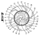
全ての実施形態のために、支持ポケット4の底面4’は2つの同心のゾーンに分けられる。内側の同心のゾーンCが中心の周りに広がり、その中に基板ホルダ2の中心開口に係合する付加的な中心ピン20がある。中心41の周りに、最初の供給チャンネル40が配置され、その中に供給ライン7の入口5が開く。供給チャンネル40は、らせん状の曲線であるガス分配チャンネル9に狭い接続チャンネル42によって接続される。ガス分配チャンネル9を通って流れるガスは、基板ホルダ2をギャップ位置に持ち上げるのみならず、また基板ホルダ2を中心41の周りの回転運動に至らせる。
For all embodiments, the bottom surface 4 'of the
ゾーンCの半径方向に外側の領域に、円形のラインであるガス収集チャンネル11がある。ガス収集チャンネル11は排出ライン13に接続される。排出ライン13は基板ホルダキャリア1を通る大きな直径の垂直の穴であり、入口5を通って供給されたガスが排出ライン13を通って再び排出される。
In the radially outer region of zone C, there is a
中央のゾーンCと外側の環状のゾーンAの間の境界は拡散障壁によって形成され、その構造は図6から知られる。支持ポケット4の底面4’の底環状溝16の中に密封リング15が挿入される。それは、底面4’から外に、基板ホルダの裏面の中の環状溝17の中に突き出す。環状溝17の幅は密封リング15の幅よりも大きい。それで、比較的小さい密封ギャップ18が生じる。それは、ゾーンAとゾーンCの間に一種のラビリンスシールを形成する。
The boundary between the central zone C and the outer annular zone A is formed by a diffusion barrier, the structure of which is known from FIG. A sealing
ゾーンAの半径方向に内側の領域では、供給チャンネル39を形成し、入り口6に接続される最初の同心のリングが支持ポケット4の底面4’の上に延びる。供給チャンネル39は、同様にらせん状の曲線であるガス分配チャンネル10に接続チャンネル43によって接続される。ゾーンAの半径方向に外側の領域にガス収集チャンネル12がある。ガス収集チャンネル12は大きな直径の排出ライン14に接続され、排出ライン14は同様に大きな直径の垂直の穴である。入口6を通って導入されたガスは排出ライン14を通って排出されることができる。
In the radially inner region of zone A, the first concentric ring forming the
基板ホルダ2の高さは実質的に支持ポケット4の深さに対応する。そして基板ホルダ2はプロセスチャンバー23に面するその表面に凹部を持ち、その凹部の中に基板3が配置される。
The height of the
図2に示される本実施形態では、供給ライン29がガス分配チャンバー27の中に開き、ガス分配チャンバー27によって半径方向に外側のゾーンに開くすべての供給ライン8が供給される。中央のゾーンCのための供給ライン28は、また共通にガス混合物を供給されることができる。
In the present embodiment shown in FIG. 2, the
図8に示される実施形態では、半径方向に外側のゾーンAの中にのみらせん状のガス分配チャンネル10がある。図9に示される実施形態では、内側のゾーンCと外側のゾーンAの両方の中にらせん状のガス分配チャンネル9、10がある。
In the embodiment shown in FIG. 8, there is a helical
図10に示される実施形態では、半径方向に外側のゾーンAの中に広いらせん状のガス分配チャンネル10がある。
In the embodiment shown in FIG. 10, there is a wide spiral
図11に示される実施形態では、半径方向に外側のゾーンAはらせんの形状である唯一のガス分配チャンネル10を持つ。図12は、図8と同様に、外側のゾーンAの中にのみ配置されたガス分配チャンネルを示す。図13は、中央のゾーンCの中にのみ複数のガス分配チャンネル9が存在する実施形態を示す。
In the embodiment shown in FIG. 11, the radially outer zone A has a single
上述されたデバイスは以下のように機能する。: The device described above functions as follows. :
コーティングプロセスの間、基板3の端は上または下に曲がる。それで、基板3の中心のみまたは基板3の端のみが基板ホルダ2の表面に平らに置かれる。それどころか、場合によっては局部的に異なるギャップの高さを持って基板3と基板ホルダ2との間にギャップが存在する。
During the coating process, the edge of the
基板3上に堆積される層の質と厚さは基板3の表面温度に非常に依存する。この後者は、局部的な熱の流入に依存している。局部的な熱の流入は、本発明に従って、支持ポケット4の底面4’と基板ホルダ2の裏面との間のガスギャップの熱伝導度特性を制御することによって調節される。支持ポケット4の中へ入口5、6を通って入るガスは、基板ホルダ2を間隔の空いたガスポジションに持ち上げる。それで、ガスクッション19が形成される。拡散障壁(密封リング15)のために、2つの分離されたガスクッション19があり、それらは入口5、6を通ってガス中間空間に入るガスによって個々に造られる。個々のゾーンA、Cに導入されたガス混合物は異なる熱伝導度を持つ。例えば、高い熱伝導度を持ったガス混合物が中心のゾーンCに導入され、低い熱伝導度を持ったガス混合物が外側のゾーンAに導入されたならば、基板ホルダ2の表面は図14中にaによって概略的に示されるような温度プロファイルに帰着する。中心のゾーンCに導入されたガスが、外側のゾーンAに導入されたガスよりもわずかに高い熱伝導度のみを持つならば、そのとき図14中にbによって示される温度プロファイルが生じる。
The quality and thickness of the layer deposited on the
外側のゾーンAに導入されたガス混合物が、中心のゾーンCに導入されたガス混合物よりも高い熱伝導度を持つならば、図14中にcによって示される温度プロファイルが生じる。例aおよびbと異なり、中心の領域は今周辺の領域より熱くはなくて、外側の領域が中心の領域より高い表面温度を持つ。導入されるガス混合物の熱伝導度の差を増やすことによって、中心の領域と外側の領域との間の温度差を更に増やすことができる。ガスの他の混合物を使うことによって、温度プロファイル曲線を定量的に制御するのみならず、定性的に制御することができ、これは例えばdによって示される温度プロファイルによって示される。 If the gas mixture introduced into the outer zone A has a higher thermal conductivity than the gas mixture introduced into the central zone C, the temperature profile indicated by c in FIG. 14 results. Unlike examples a and b, the central region is now no hotter than the surrounding region, and the outer region has a higher surface temperature than the central region. By increasing the difference in thermal conductivity of the introduced gas mixture, the temperature difference between the central region and the outer region can be further increased. By using other mixtures of gases, the temperature profile curve can be controlled not only quantitatively, but also qualitatively, as indicated by the temperature profile indicated, for example, by d.
図15に示されるガス混合システムでは、2つのガス35、36、すなわち、窒素と水素が供給される。個々のガスは、供給ラインと切替バルブ34を経由してマスフローコントローラ32、33に供給される。本実施形態では、3つの基板ホルダが与えられ、それらはいずれも中央のゾーンCに別々にガス35、36の混合物を供給される。ガスの流れはマスフローコントローラ32、33によって、適切に調節される。
In the gas mixing system shown in FIG. 15, two
外側の環状のゾーンは、同様な方法で切替バルブ34’とマスフローコントローラ32’、33’を経由してガス混合物を供給される。本実施形態では、圧力調整器44が内側のゾーンCと外側のゾーンAへの供給ラインの間に与えられる。この圧力調整器は差分圧力センサである。それで、2つのゾーンAとCの圧力差が設定されることができる。ゾーンAへの供給ラインの圧力は、さらにスルーフロー圧力調節器45によって設定される。スルーフロー圧力調節器45は排出ラインに接続される。
The outer annular zone is fed with a gas mixture in a similar manner via switching valve 34 'and mass flow controllers 32', 33 '. In this embodiment, a
全ての開示された特徴は、(それ自体で)本発明に関連する。関係する/添付の優先権書類(先の出願のコピー)の開示内容もまた、本願の特許請求の範囲にこれらの書類の特徴を包含させる目的も含め、その出願の開示全体をここに含める。従属する請求項は、それらの選択的に従属する構成において、特にこれらの請求項に基づいて部分的に応用する目的のために先行技術の独立した発明の発展を特徴づける。 All disclosed features are (in themselves) relevant to the present invention. The disclosure content of the related / attached priority document (a copy of the previous application) is also hereby incorporated by reference in its entirety, including the purpose of including the features of these documents in the claims of this application. The dependent claims characterize the development of the independent invention of the prior art in their selectively dependent configurations, in particular for the purpose of partial application based on these claims.
1 基板ホルダキャリア
2 基板ホルダ
3 基板
4 支持ポケット
4‘ 支持ポケットの底面
5 入口
6 入口
7 供給ライン
8 供給ライン
9 ガス分配チャンネル
10 ガス分配チャンネル
11 ガス収集チャンネル
12 ガス収集チャンネル
13 排出ライン
14 排出ライン
15 拡散障壁(密封リング)
16 底環状溝
17 環状溝
18 密封ギャップ
19 ガスクッション
20 中心ピン
21 ガス注入口
22 カバー
23 プロセスチャンバー
24 ガス排出口
25 中央プレート
26 中央キャリア
27 ガス分配チャンバー
28 供給ライン
29 供給ライン
30 ヒーター
31 反応炉ハウジング
32 マスフローコントローラ
32‘ マスフローコントローラ
33 マスフローコントローラ
33‘ マスフローコントローラ
34 切替バルブ
34‘ 切替バルブ
35 ガス供給源
36 ガス供給源
37 ガス供給源
38 外側のライン
39 供給チャンネル
40 供給チャンネル
41 中心
42 接続チャンネル
43 接続チャンネル
44 圧力調整器
45 スルーフロー圧力調節器
A 外側の環状のゾーン
C 内側の同心のゾーン
a 温度プロファイル
b 温度プロファイル
c 温度プロファイル
d 温度プロファイル
DESCRIPTION OF
16 bottom
A Outer annular zone C Inner concentric zone
a temperature profile b temperature profile c temperature profile d temperature profile
Claims (11)
前記基板ホルダキャリア(1)が少なくとも1つの支持面(4‘)を備え、複数のガス供給ライン(7、8)が当該支持面(4‘)に開き、
前記基板ホルダキャリア(1)が基板ホルダ(2)を備え、当該基板ホルダ(2)の裏面が前記支持面(4‘)に面し、
前記支持面(4‘)と前記基板ホルダ(2)の裏面との間の空間に前記ガス供給ライン(7、8)を通って供給されるガスが、前記基板ホルダ(2)を運ぶガスクッション(19)を形成し、
前記ガスクッション(19)が、各々関連する前記ガス供給ライン(7、8)を通って個別に供給されることができる複数のゾーン(A、C)を備え、
前記ゾーン(A、C)が、当該ゾーン(A、C)の間でガスの交換を抑制する手段によってお互いから分離されており、
ガス排出ライン(13、14)が少なくとも内側のゾーン(C)と関連し、当該ガス排出ライン(13、14)を通って、前記内側のゾーン(C)に前記ガス供給ライン(7、8)を通って供給されるガスを排出することができる、
ことを特徴とするCVD反応炉。 A CVD reactor comprising a process chamber (23) and a substrate holder carrier (1) located in the process chamber (23),
The substrate holder carrier (1) comprises at least one support surface (4 ′), a plurality of gas supply lines (7, 8) open to the support surface (4 ′);
The substrate holder carrier (1) includes a substrate holder (2), and the back surface of the substrate holder (2) faces the support surface (4 ′),
A gas cushion in which gas supplied through the gas supply lines (7, 8) to the space between the support surface (4 ′) and the back surface of the substrate holder (2) carries the substrate holder (2). (19)
The gas cushion (19) comprises a plurality of zones (A, C) each capable of being supplied individually through the associated gas supply line (7, 8);
The zones (A, C) are separated from each other by means of inhibiting gas exchange between the zones (A, C);
A gas discharge line (13, 14) is associated with at least the inner zone (C) and passes through the gas discharge line (13, 14) to the inner zone (C) to the gas supply line (7, 8). The gas supplied through can be discharged,
A CVD reactor characterized by that.
前記密封リング(15)が、前記2つのゾーン(A、C)のガスクッションの間に何回も方向を変えるギャップのみが残るように、対向する面、特に前記基板ホルダ(2)の裏面に位置する環状溝(17)に係合する、
ことを特徴とする請求項2に記載のCVD反応炉。 The diffusion barrier protrudes above the surface of the substrate holder carrier (1), in particular the support surface (4 ′), in particular a sealing ring (15) inserted into the bottom annular groove (16);
The sealing ring (15) is on the opposite side, in particular on the back side of the substrate holder (2), so that only a gap that changes direction many times remains between the gas cushions of the two zones (A, C). Engaging the annular groove (17) located,
The CVD reactor according to claim 2.
前記支持ポケット(4)の底面(4‘)が、前記支持面を形成し、
前記基板ホルダ(2)の裏面が、前記支持ポケット(4)の底面(4‘)と並行であり、
基板(3)が、前記基板ホルダ(2)上で前記プロセスチャンバー(23)のカバー(22)の方向に上方に面する前記基板ホルダ(2)の表面に配置されることができ、
前記支持ポケット(4)の底面(4‘)が、供給チャンネル(39、40)と、当該供給チャンネル(39、40)とつながっており、特にらせん状であるガス分配チャンネル(9、10)とを備え、
前記ガス分配チャンネル(9、10)が、前記ガス排出ライン(13、14)とつながるガス収集チャンネル(11、12)によって囲まれる、
ことを特徴とする請求項1ないし4のいずれか1項に記載のCVD反応炉。 The substrate holder (2) is wrapped in a support pocket (4) of the substrate holder carrier (1);
The bottom surface (4 ′) of the support pocket (4) forms the support surface;
The back surface of the substrate holder (2) is parallel to the bottom surface (4 ′) of the support pocket (4);
A substrate (3) can be arranged on the surface of the substrate holder (2) facing upwards in the direction of the cover (22) of the process chamber (23) on the substrate holder (2);
The bottom surface (4 ′) of the support pocket (4) is connected to the supply channel (39, 40) and to the supply channel (39, 40), in particular a spiral gas distribution channel (9, 10). With
The gas distribution channels (9, 10) are surrounded by gas collection channels (11, 12) connected to the gas discharge lines (13, 14);
The CVD reactor according to any one of claims 1 to 4, wherein:
前記各基板ホルダ(2)は前記複数のゾーン(A、C)を持つ前記ガスクッション(19)によって運ばれ、
前記ガス供給ライン(7、8)が個々の前記ゾーン(A、C)のために与えられ、前記ガス供給ライン(7、8)はガス供給デバイスに個別に接続されるか、または共通のガス供給デバイスに接続される、
ことを特徴とする請求項1ないし6のいずれか1項に記載のCVD反応炉。 A number of support pockets (4) are arranged in a circle around the center of the substrate holder carrier (1), each support pocket (4) can accommodate the substrate holder (2),
Each substrate holder (2) is carried by the gas cushion (19) having the plurality of zones (A, C);
Said gas supply line (7, 8) is provided for each said zone (A, C), said gas supply line (7, 8) being individually connected to a gas supply device or a common gas Connected to the supply device,
The CVD reactor according to any one of claims 1 to 6, characterized in that:
前記ガスクッション(19)が、特にお互いに関して同軸上に配置された複数のゾーン(A、C)を持ち、
前記複数のゾーン(A、C)の中にお互いに異なる熱伝導特性を持つガス(35、36、37)またはガス混合物が供給され、当該熱伝導特性は特に前記ガス混合物を変えることによって調節することができる、
ことを特徴とする基板ホルダの表面温度の制御方法。 A method for controlling the surface temperature of a substrate holder (2) heated from below and carried in a dynamic gas cushion (19), in particular driven to rotate,
The gas cushion (19) has a plurality of zones (A, C) arranged coaxially, in particular with respect to each other;
Gases (35, 36, 37) or gas mixtures having different heat transfer properties are supplied into the zones (A, C), the heat transfer properties being adjusted in particular by changing the gas mixture. be able to,
A method for controlling the surface temperature of a substrate holder, wherein:
前記基板ホルダキャリア(1)が、前記プロセスチャンバー(23)に面する表面上の支持面(4‘)で基板ホルダ(2)を運び、ヒーター(30)によって裏面から加熱されることができ、
ガス供給ライン(7、8)が、前記支持面(4‘)に開き、
前記ガス供給ライン(7、8)が、ガス混合システムによって前記基板ホルダ(2)を運ぶ動的なガスクッション(19)を形成するガスを供給され、
前記ガスクッション(19)がお互いに隣接する複数のゾーン(A、C)を備え、当該複数のゾーン(A、C)が個々の前記ガス供給ライン(7、8)を通って前記ガス混合システムから供給され、
前記ガス混合システムが、お互いに異なるガス、またはガス混合物を前記個々のガス供給ライン(7、8)に対して供給することができるガス流制御エレメント(32、33、34)を備える、
ことを特徴とする基板処理装置。 A substrate processing apparatus comprising a CVD reactor having a process chamber (23) and a substrate holder carrier (1) disposed in the process chamber (23),
The substrate holder carrier (1) carries the substrate holder (2) with a support surface (4 ′) on the surface facing the process chamber (23) and can be heated from the back by a heater (30),
Gas supply lines (7, 8) open on the support surface (4 ′),
The gas supply lines (7, 8) are fed with gas forming a dynamic gas cushion (19) carrying the substrate holder (2) by a gas mixing system;
The gas cushion (19) includes a plurality of zones (A, C) adjacent to each other, and the plurality of zones (A, C) pass through the gas supply lines (7, 8). Supplied from and
The gas mixing system comprises gas flow control elements (32, 33, 34) capable of supplying different gases or gas mixtures to the individual gas supply lines (7, 8).
A substrate processing apparatus.
前記ガスの組成の調節によって各前記ゾーン(A、C)における前記ガスクッション(19)の熱伝導特性を個別に調節するために、お互いに異なる熱伝導特性を持つ2つのガスが前記ガス流制御エレメント(32、33、34)によって個別に混合されることができる、
ことを特徴とする請求項10に記載の基板処理装置。 The gas mixing system comprises a first gas supply (35) for a first gas and a second gas supply (36) for a second gas;
In order to individually adjust the heat conduction characteristics of the gas cushion (19) in each of the zones (A, C) by adjusting the composition of the gas, two gases having different heat conduction characteristics are controlled by the gas flow control. Can be individually mixed by the elements (32, 33, 34),
The substrate processing apparatus according to claim 10.
Applications Claiming Priority (3)
| Application Number | Priority Date | Filing Date | Title |
|---|---|---|---|
| DE102009044276.6 | 2009-10-16 | ||
| DE102009044276A DE102009044276A1 (en) | 2009-10-16 | 2009-10-16 | CVD reactor with multi-zone gas cushion substrate holder |
| PCT/EP2010/065105 WO2011045241A1 (en) | 2009-10-16 | 2010-10-08 | Cvd reactor having a substrate holder resting on a gas cushion comprising a plurality of zones |
Publications (2)
| Publication Number | Publication Date |
|---|---|
| JP2013507779A true JP2013507779A (en) | 2013-03-04 |
| JP5732466B2 JP5732466B2 (en) | 2015-06-10 |
Family
ID=43064427
Family Applications (1)
| Application Number | Title | Priority Date | Filing Date |
|---|---|---|---|
| JP2012533582A Expired - Fee Related JP5732466B2 (en) | 2009-10-16 | 2010-10-08 | CVD reactor with substrate holder placed on a gas cushion consisting of multiple zones |
Country Status (8)
| Country | Link |
|---|---|
| US (1) | US9447500B2 (en) |
| EP (1) | EP2488679B1 (en) |
| JP (1) | JP5732466B2 (en) |
| KR (1) | KR101770577B1 (en) |
| CN (1) | CN102656294B (en) |
| DE (1) | DE102009044276A1 (en) |
| TW (1) | TWI523974B (en) |
| WO (1) | WO2011045241A1 (en) |
Cited By (3)
| Publication number | Priority date | Publication date | Assignee | Title |
|---|---|---|---|---|
| KR20190129917A (en) * | 2017-03-20 | 2019-11-20 | 아익스트론 에스이 | Susceptor in CVD-reactor |
| JP2022512210A (en) * | 2018-12-11 | 2022-02-02 | アイクストロン、エスイー | CVD reactor susceptor |
| JP2022521176A (en) * | 2019-02-21 | 2022-04-06 | アイクストロン、エスイー | CVD reactor with means to locally affect susceptor temperature |
Families Citing this family (29)
| Publication number | Priority date | Publication date | Assignee | Title |
|---|---|---|---|---|
| JP5409413B2 (en) * | 2010-01-26 | 2014-02-05 | 日本パイオニクス株式会社 | III-nitride semiconductor vapor phase growth system |
| KR20110136583A (en) * | 2010-06-15 | 2011-12-21 | 삼성엘이디 주식회사 | Susceptor and chemical vapor deposition apparatus having the same |
| DE102011055061A1 (en) * | 2011-11-04 | 2013-05-08 | Aixtron Se | CVD reactor or substrate holder for a CVD reactor |
| DE102012101923B4 (en) | 2012-03-07 | 2019-11-07 | Osram Opto Semiconductors Gmbh | Substrate carrier assembly, coating system with substrate carrier assembly and method for performing a coating method |
| TWI506163B (en) * | 2012-07-13 | 2015-11-01 | Epistar Corp | Reactive apparatus for vapor deposition and carrier thereof |
| DE102012108986A1 (en) | 2012-09-24 | 2014-03-27 | Aixtron Se | Substrate holder for use in process chamber of semiconductor substrate treatment device, has recess having bearing surfaces which lie in common plane, and wall in region of projections in plan view of top face is straight |
| DE102014104218A1 (en) * | 2014-03-26 | 2015-10-01 | Aixtron Se | CVD reactor with feed-zone temperature control |
| KR102372893B1 (en) | 2014-12-04 | 2022-03-10 | 삼성전자주식회사 | Chemical vapor deposition apparatus for fabricating light emitting diode(LED) |
| CN104835763B (en) * | 2015-04-27 | 2018-08-14 | 沈阳拓荆科技有限公司 | A kind of controllable temperature heating dish of petal surface texture |
| US9738975B2 (en) | 2015-05-12 | 2017-08-22 | Lam Research Corporation | Substrate pedestal module including backside gas delivery tube and method of making |
| CN105047543A (en) * | 2015-06-17 | 2015-11-11 | 沈阳拓荆科技有限公司 | Controllable temperature heating disc of spiral-type surface structure |
| CN106684029B (en) * | 2015-11-10 | 2021-01-08 | 北京北方华创微电子装备有限公司 | Bearing device and semiconductor processing equipment |
| CN105547322B (en) * | 2016-01-07 | 2018-05-11 | 交通运输部公路科学研究所 | A kind of method that VMT Vehicle-Miles of Travel calculating is carried out using satellite location data |
| DE102016110788A1 (en) * | 2016-06-13 | 2017-12-14 | Aixtron Se | Apparatus and method for the production of optoelectronic components, in particular of multi-junction solar cells in a continuous process |
| EP3574127A1 (en) * | 2017-01-27 | 2019-12-04 | Aixtron SE | Transport ring |
| KR102369676B1 (en) | 2017-04-10 | 2022-03-04 | 삼성디스플레이 주식회사 | Apparatus and method for manufacturing a display apparatus |
| JP7321768B2 (en) * | 2018-05-23 | 2023-08-07 | 信越化学工業株式会社 | Chemical vapor deposition apparatus and film forming method |
| DE102018123281A1 (en) * | 2018-09-21 | 2020-03-26 | Aixtron Se | CVD reactor with substrate holders rotatably mounted on a gas cushion |
| DE102018124957A1 (en) * | 2018-10-10 | 2020-04-16 | Aixtron Se | CVD reactor with substrate holders resting on gas cushions |
| DE102018132673A1 (en) | 2018-12-18 | 2020-06-18 | Aixtron Se | Susceptor for a CVD reactor |
| CN109594063A (en) * | 2018-12-27 | 2019-04-09 | 西安奕斯伟硅片技术有限公司 | A kind of extension consersion unit |
| CN110172683A (en) * | 2019-06-27 | 2019-08-27 | 云谷(固安)科技有限公司 | Heating mechanism, plasma chamber and the method to form a film on substrate |
| KR102238016B1 (en) * | 2019-11-07 | 2021-04-08 | 주식회사 한화 | Apparatus for processing substrate |
| DE102020105753A1 (en) | 2020-03-04 | 2021-09-09 | Aixtron Se | A substrate holder for a CVD reactor provided with a large number of structural elements on an underside |
| DE102020107517A1 (en) | 2020-03-18 | 2021-09-23 | Aixtron Se | Susceptor for a CVD reactor |
| TWI729778B (en) * | 2020-04-21 | 2021-06-01 | 錼創顯示科技股份有限公司 | Tray structure |
| DE102020127662A1 (en) | 2020-10-21 | 2022-04-21 | Aixtron Se | Susceptor for a CVD reactor |
| CN114908334B (en) * | 2021-02-09 | 2025-10-14 | 中微半导体设备(上海)股份有限公司 | Lower electrode assembly, chemical vapor deposition device and substrate temperature control method |
| CN115029774B (en) * | 2022-06-20 | 2024-11-26 | 北京北方华创微电子装备有限公司 | Semiconductor process equipment and its carrier |
Citations (15)
| Publication number | Priority date | Publication date | Assignee | Title |
|---|---|---|---|---|
| US4860687A (en) * | 1986-03-21 | 1989-08-29 | U.S. Philips Corporation | Device comprising a flat susceptor rotating parallel to a reference surface about a shift perpendicular to this surface |
| JPH03135014A (en) * | 1989-10-20 | 1991-06-10 | Furukawa Electric Co Ltd:The | Film formation apparatus for wafer |
| US5033538A (en) * | 1989-05-08 | 1991-07-23 | Balzers Aktiengesellschaft | Workpiece carrier for a disk-shaped workpiece as well as a vacuum process space |
| US5177878A (en) * | 1989-05-08 | 1993-01-12 | U.S. Philips Corporation | Apparatus and method for treating flat substrate under reduced pressure in the manufacture of electronic devices |
| JPH07335630A (en) * | 1994-06-13 | 1995-12-22 | Hitachi Ltd | Vacuum processing device |
| US6182602B1 (en) * | 1996-07-15 | 2001-02-06 | Applied Materials, Inc. | Inductively coupled HDP-CVD reactor |
| JP2002280373A (en) * | 2001-03-19 | 2002-09-27 | Hitachi Kokusai Electric Inc | Substrate processing equipment |
| WO2003008675A1 (en) * | 2001-07-12 | 2003-01-30 | Aixtron Ag | Process chamber with a base with sectionally different rotational drive and layer deposition method in such a process chamber |
| JP2004014952A (en) * | 2002-06-10 | 2004-01-15 | Tokyo Electron Ltd | Processing system and processing method |
| JP2005505123A (en) * | 2000-11-11 | 2005-02-17 | アイクストロン、アーゲー | Method and apparatus for substrate surface temperature control in a CVD reactor |
| JP2005522876A (en) * | 2002-04-08 | 2005-07-28 | クリー インコーポレイテッド | Gas-driven satellite rotator and method for forming a silicon carbide layer |
| WO2007122147A1 (en) * | 2006-04-21 | 2007-11-01 | Aixtron Ag | Apparatus and method for controlling the surface temperature of a substrate in a process chamber |
| US20070256786A1 (en) * | 2006-05-03 | 2007-11-08 | Xiaoping Zhou | Apparatus for etching high aspect ratio features |
| US20080227227A1 (en) * | 2007-03-12 | 2008-09-18 | Tokyo Electron Limited | Dynamic temperature backside gas control for improved within-substrate process uniformity |
| WO2008148759A1 (en) * | 2007-06-06 | 2008-12-11 | Aixtron Ag | Device for the temperature control of the surface temperatures of substrates in a cvd reactor |
Family Cites Families (6)
| Publication number | Priority date | Publication date | Assignee | Title |
|---|---|---|---|---|
| US5468299A (en) * | 1995-01-09 | 1995-11-21 | Tsai; Charles S. | Device comprising a flat susceptor rotating parallel to a reference surface about a shaft perpendicular to this surface |
| US6053982A (en) * | 1995-09-01 | 2000-04-25 | Asm America, Inc. | Wafer support system |
| US6040011A (en) * | 1998-06-24 | 2000-03-21 | Applied Materials, Inc. | Substrate support member with a purge gas channel and pumping system |
| US6853953B2 (en) * | 2001-08-07 | 2005-02-08 | Tokyo Electron Limited | Method for characterizing the performance of an electrostatic chuck |
| US7156951B1 (en) | 2002-06-21 | 2007-01-02 | Lam Research Corporation | Multiple zone gas distribution apparatus for thermal control of semiconductor wafer |
| KR101405346B1 (en) * | 2008-01-04 | 2014-06-12 | 삼성디스플레이 주식회사 | Substrate pedestal, apparatus for treating substrate having it and the method for aligning substrate |
-
2009
- 2009-10-16 DE DE102009044276A patent/DE102009044276A1/en not_active Withdrawn
-
2010
- 2010-10-08 WO PCT/EP2010/065105 patent/WO2011045241A1/en not_active Ceased
- 2010-10-08 KR KR1020127012630A patent/KR101770577B1/en active Active
- 2010-10-08 US US13/502,356 patent/US9447500B2/en active Active
- 2010-10-08 EP EP10763696.1A patent/EP2488679B1/en active Active
- 2010-10-08 CN CN201080057579.5A patent/CN102656294B/en active Active
- 2010-10-08 JP JP2012533582A patent/JP5732466B2/en not_active Expired - Fee Related
- 2010-10-11 TW TW099134552A patent/TWI523974B/en active
Patent Citations (17)
| Publication number | Priority date | Publication date | Assignee | Title |
|---|---|---|---|---|
| US4860687A (en) * | 1986-03-21 | 1989-08-29 | U.S. Philips Corporation | Device comprising a flat susceptor rotating parallel to a reference surface about a shift perpendicular to this surface |
| US5033538A (en) * | 1989-05-08 | 1991-07-23 | Balzers Aktiengesellschaft | Workpiece carrier for a disk-shaped workpiece as well as a vacuum process space |
| US5177878A (en) * | 1989-05-08 | 1993-01-12 | U.S. Philips Corporation | Apparatus and method for treating flat substrate under reduced pressure in the manufacture of electronic devices |
| JPH03135014A (en) * | 1989-10-20 | 1991-06-10 | Furukawa Electric Co Ltd:The | Film formation apparatus for wafer |
| JPH07335630A (en) * | 1994-06-13 | 1995-12-22 | Hitachi Ltd | Vacuum processing device |
| US6182602B1 (en) * | 1996-07-15 | 2001-02-06 | Applied Materials, Inc. | Inductively coupled HDP-CVD reactor |
| JP2005505123A (en) * | 2000-11-11 | 2005-02-17 | アイクストロン、アーゲー | Method and apparatus for substrate surface temperature control in a CVD reactor |
| JP2002280373A (en) * | 2001-03-19 | 2002-09-27 | Hitachi Kokusai Electric Inc | Substrate processing equipment |
| WO2003008675A1 (en) * | 2001-07-12 | 2003-01-30 | Aixtron Ag | Process chamber with a base with sectionally different rotational drive and layer deposition method in such a process chamber |
| JP2005522876A (en) * | 2002-04-08 | 2005-07-28 | クリー インコーポレイテッド | Gas-driven satellite rotator and method for forming a silicon carbide layer |
| JP2004014952A (en) * | 2002-06-10 | 2004-01-15 | Tokyo Electron Ltd | Processing system and processing method |
| WO2007122147A1 (en) * | 2006-04-21 | 2007-11-01 | Aixtron Ag | Apparatus and method for controlling the surface temperature of a substrate in a process chamber |
| US20090110805A1 (en) * | 2006-04-21 | 2009-04-30 | Aixtron Inc. | Apparatus and Method for Controlling the Surface Temperature of a Substrate in a Process Chamber |
| JP2009534824A (en) * | 2006-04-21 | 2009-09-24 | アイクストロン、アーゲー | Apparatus and method for controlling substrate surface temperature in process chamber |
| US20070256786A1 (en) * | 2006-05-03 | 2007-11-08 | Xiaoping Zhou | Apparatus for etching high aspect ratio features |
| US20080227227A1 (en) * | 2007-03-12 | 2008-09-18 | Tokyo Electron Limited | Dynamic temperature backside gas control for improved within-substrate process uniformity |
| WO2008148759A1 (en) * | 2007-06-06 | 2008-12-11 | Aixtron Ag | Device for the temperature control of the surface temperatures of substrates in a cvd reactor |
Cited By (8)
| Publication number | Priority date | Publication date | Assignee | Title |
|---|---|---|---|---|
| KR20190129917A (en) * | 2017-03-20 | 2019-11-20 | 아익스트론 에스이 | Susceptor in CVD-reactor |
| JP2020515069A (en) * | 2017-03-20 | 2020-05-21 | アイクストロン、エスイー | Susceptor for CVD reactor |
| JP7092790B2 (en) | 2017-03-20 | 2022-06-28 | アイクストロン、エスイー | Suceptor for CVD reactor |
| KR102567393B1 (en) * | 2017-03-20 | 2023-08-14 | 아익스트론 에스이 | CVD-reactor susceptor |
| JP2022512210A (en) * | 2018-12-11 | 2022-02-02 | アイクストロン、エスイー | CVD reactor susceptor |
| JP7458400B2 (en) | 2018-12-11 | 2024-03-29 | アイクストロン、エスイー | CVD reactor susceptor |
| JP2022521176A (en) * | 2019-02-21 | 2022-04-06 | アイクストロン、エスイー | CVD reactor with means to locally affect susceptor temperature |
| JP7475357B2 (en) | 2019-02-21 | 2024-04-26 | アイクストロン、エスイー | CVD reactor having means for locally influencing susceptor temperature - Patents.com |
Also Published As
| Publication number | Publication date |
|---|---|
| US20120204796A1 (en) | 2012-08-16 |
| TW201124556A (en) | 2011-07-16 |
| CN102656294A (en) | 2012-09-05 |
| CN102656294B (en) | 2014-06-11 |
| US9447500B2 (en) | 2016-09-20 |
| EP2488679A1 (en) | 2012-08-22 |
| DE102009044276A1 (en) | 2011-05-05 |
| JP5732466B2 (en) | 2015-06-10 |
| KR20120083470A (en) | 2012-07-25 |
| WO2011045241A1 (en) | 2011-04-21 |
| TWI523974B (en) | 2016-03-01 |
| KR101770577B1 (en) | 2017-08-23 |
| EP2488679B1 (en) | 2014-11-26 |
Similar Documents
| Publication | Publication Date | Title |
|---|---|---|
| JP5732466B2 (en) | CVD reactor with substrate holder placed on a gas cushion consisting of multiple zones | |
| US8308867B2 (en) | Device for the temperature control of the surface temperatures of substrates in a CVD reactor | |
| JP5358427B2 (en) | Apparatus and method for controlling substrate surface temperature in process chamber | |
| US20230383408A1 (en) | Methods for thermal treatment of substrates | |
| JP5619164B2 (en) | CVD method and CVD reactor | |
| JP7682263B2 (en) | CVD reactor with temperature adjustable gas inlet region - Patents.com | |
| KR102697917B1 (en) | Devices and methods for improving thermal chemical vapor deposition (CVD) uniformity | |
| TW201027599A (en) | MOCVD reactor having cylindrical gas inlet element | |
| CN115298351B (en) | Susceptor for CVD reactor | |
| US12018372B2 (en) | Gas injector for epitaxy and CVD chamber | |
| TW202035779A (en) | Susceptor of a CVD reactor | |
| EP0473067B1 (en) | Wafer processing reactor | |
| TW202434757A (en) | Method and apparatus for depositing a SiC layer on a substrate | |
| KR20250121017A (en) | Method and device for depositing SiC layers on a substrate | |
| TW202432886A (en) | Device for depositing a SiC layer on a substrate with an adjustable exhaust element |
Legal Events
| Date | Code | Title | Description |
|---|---|---|---|
| A621 | Written request for application examination |
Free format text: JAPANESE INTERMEDIATE CODE: A621 Effective date: 20130926 |
|
| A977 | Report on retrieval |
Free format text: JAPANESE INTERMEDIATE CODE: A971007 Effective date: 20140929 |
|
| A131 | Notification of reasons for refusal |
Free format text: JAPANESE INTERMEDIATE CODE: A131 Effective date: 20141007 |
|
| A521 | Request for written amendment filed |
Free format text: JAPANESE INTERMEDIATE CODE: A523 Effective date: 20141031 |
|
| TRDD | Decision of grant or rejection written | ||
| A01 | Written decision to grant a patent or to grant a registration (utility model) |
Free format text: JAPANESE INTERMEDIATE CODE: A01 Effective date: 20150324 |
|
| A61 | First payment of annual fees (during grant procedure) |
Free format text: JAPANESE INTERMEDIATE CODE: A61 Effective date: 20150413 |
|
| R150 | Certificate of patent or registration of utility model |
Ref document number: 5732466 Country of ref document: JP Free format text: JAPANESE INTERMEDIATE CODE: R150 |
|
| R250 | Receipt of annual fees |
Free format text: JAPANESE INTERMEDIATE CODE: R250 |
|
| R250 | Receipt of annual fees |
Free format text: JAPANESE INTERMEDIATE CODE: R250 |
|
| R250 | Receipt of annual fees |
Free format text: JAPANESE INTERMEDIATE CODE: R250 |
|
| R250 | Receipt of annual fees |
Free format text: JAPANESE INTERMEDIATE CODE: R250 |
|
| R250 | Receipt of annual fees |
Free format text: JAPANESE INTERMEDIATE CODE: R250 |
|
| R250 | Receipt of annual fees |
Free format text: JAPANESE INTERMEDIATE CODE: R250 |
|
| R250 | Receipt of annual fees |
Free format text: JAPANESE INTERMEDIATE CODE: R250 |
|
| LAPS | Cancellation because of no payment of annual fees |