JP2013505137A - Laser method for producing easily cut material and product thereof - Google Patents
Laser method for producing easily cut material and product thereof Download PDFInfo
- Publication number
- JP2013505137A JP2013505137A JP2012529925A JP2012529925A JP2013505137A JP 2013505137 A JP2013505137 A JP 2013505137A JP 2012529925 A JP2012529925 A JP 2012529925A JP 2012529925 A JP2012529925 A JP 2012529925A JP 2013505137 A JP2013505137 A JP 2013505137A
- Authority
- JP
- Japan
- Prior art keywords
- laser
- sheet material
- material according
- line
- etched
- Prior art date
- Legal status (The legal status is an assumption and is not a legal conclusion. Google has not performed a legal analysis and makes no representation as to the accuracy of the status listed.)
- Withdrawn
Links
- 239000000463 material Substances 0.000 title claims abstract description 193
- 238000004519 manufacturing process Methods 0.000 title claims description 29
- 238000000034 method Methods 0.000 claims abstract description 35
- 238000010329 laser etching Methods 0.000 claims abstract description 7
- 238000011156 evaluation Methods 0.000 claims description 22
- 238000002474 experimental method Methods 0.000 claims description 22
- 238000013401 experimental design Methods 0.000 claims description 18
- 238000000926 separation method Methods 0.000 claims description 16
- 238000005530 etching Methods 0.000 claims description 10
- 230000000149 penetrating effect Effects 0.000 claims description 4
- 238000007619 statistical method Methods 0.000 claims description 3
- NIXOWILDQLNWCW-UHFFFAOYSA-N acrylic acid group Chemical group C(C=C)(=O)O NIXOWILDQLNWCW-UHFFFAOYSA-N 0.000 claims description 2
- 239000002390 adhesive tape Substances 0.000 claims description 2
- 230000001419 dependent effect Effects 0.000 claims description 2
- 238000005553 drilling Methods 0.000 abstract description 9
- 239000005026 oriented polypropylene Substances 0.000 description 12
- 239000000047 product Substances 0.000 description 11
- 230000003287 optical effect Effects 0.000 description 8
- 230000008569 process Effects 0.000 description 7
- 238000013461 design Methods 0.000 description 6
- 239000002655 kraft paper Substances 0.000 description 5
- 238000005457 optimization Methods 0.000 description 4
- 239000000123 paper Substances 0.000 description 4
- 238000012545 processing Methods 0.000 description 4
- 239000000853 adhesive Substances 0.000 description 3
- 230000001070 adhesive effect Effects 0.000 description 3
- 230000008859 change Effects 0.000 description 3
- 230000000694 effects Effects 0.000 description 3
- 238000005516 engineering process Methods 0.000 description 3
- 238000012986 modification Methods 0.000 description 3
- 230000004048 modification Effects 0.000 description 3
- 230000008901 benefit Effects 0.000 description 2
- 229920006378 biaxially oriented polypropylene Polymers 0.000 description 2
- 239000011127 biaxially oriented polypropylene Substances 0.000 description 2
- 238000007796 conventional method Methods 0.000 description 2
- 238000005520 cutting process Methods 0.000 description 2
- 230000002349 favourable effect Effects 0.000 description 2
- 239000011888 foil Substances 0.000 description 2
- 230000003993 interaction Effects 0.000 description 2
- 238000012417 linear regression Methods 0.000 description 2
- 229910052751 metal Inorganic materials 0.000 description 2
- 239000002184 metal Substances 0.000 description 2
- 238000004806 packaging method and process Methods 0.000 description 2
- 230000000737 periodic effect Effects 0.000 description 2
- 239000004033 plastic Substances 0.000 description 2
- 238000000611 regression analysis Methods 0.000 description 2
- 230000004044 response Effects 0.000 description 2
- 239000007787 solid Substances 0.000 description 2
- 230000001360 synchronised effect Effects 0.000 description 2
- 239000003522 acrylic cement Substances 0.000 description 1
- 230000004075 alteration Effects 0.000 description 1
- 229910052782 aluminium Inorganic materials 0.000 description 1
- XAGFODPZIPBFFR-UHFFFAOYSA-N aluminium Chemical compound [Al] XAGFODPZIPBFFR-UHFFFAOYSA-N 0.000 description 1
- JNDMLEXHDPKVFC-UHFFFAOYSA-N aluminum;oxygen(2-);yttrium(3+) Chemical compound [O-2].[O-2].[O-2].[Al+3].[Y+3] JNDMLEXHDPKVFC-UHFFFAOYSA-N 0.000 description 1
- 230000003466 anti-cipated effect Effects 0.000 description 1
- 239000007795 chemical reaction product Substances 0.000 description 1
- 238000005094 computer simulation Methods 0.000 description 1
- 238000010219 correlation analysis Methods 0.000 description 1
- 230000007547 defect Effects 0.000 description 1
- 230000001747 exhibiting effect Effects 0.000 description 1
- 239000012467 final product Substances 0.000 description 1
- 239000012530 fluid Substances 0.000 description 1
- 230000006870 function Effects 0.000 description 1
- 239000011261 inert gas Substances 0.000 description 1
- 239000010985 leather Substances 0.000 description 1
- 238000012423 maintenance Methods 0.000 description 1
- 238000001000 micrograph Methods 0.000 description 1
- 239000000203 mixture Substances 0.000 description 1
- 238000012544 monitoring process Methods 0.000 description 1
- 229920003052 natural elastomer Polymers 0.000 description 1
- 229920001194 natural rubber Polymers 0.000 description 1
- 238000013488 ordinary least square regression Methods 0.000 description 1
- 239000002904 solvent Substances 0.000 description 1
- 239000000758 substrate Substances 0.000 description 1
- 229920003051 synthetic elastomer Polymers 0.000 description 1
- 239000005061 synthetic rubber Substances 0.000 description 1
- 238000012360 testing method Methods 0.000 description 1
- 230000001052 transient effect Effects 0.000 description 1
- 229910019901 yttrium aluminum garnet Inorganic materials 0.000 description 1
Images


Classifications
-
- B—PERFORMING OPERATIONS; TRANSPORTING
- B23—MACHINE TOOLS; METAL-WORKING NOT OTHERWISE PROVIDED FOR
- B23K—SOLDERING OR UNSOLDERING; WELDING; CLADDING OR PLATING BY SOLDERING OR WELDING; CUTTING BY APPLYING HEAT LOCALLY, e.g. FLAME CUTTING; WORKING BY LASER BEAM
- B23K26/00—Working by laser beam, e.g. welding, cutting or boring
- B23K26/08—Devices involving relative movement between laser beam and workpiece
- B23K26/083—Devices involving movement of the workpiece in at least one axial direction
- B23K26/0838—Devices involving movement of the workpiece in at least one axial direction by using an endless conveyor belt
- B23K26/0846—Devices involving movement of the workpiece in at least one axial direction by using an endless conveyor belt for moving elongated workpieces longitudinally, e.g. wire or strip material
-
- B—PERFORMING OPERATIONS; TRANSPORTING
- B23—MACHINE TOOLS; METAL-WORKING NOT OTHERWISE PROVIDED FOR
- B23K—SOLDERING OR UNSOLDERING; WELDING; CLADDING OR PLATING BY SOLDERING OR WELDING; CUTTING BY APPLYING HEAT LOCALLY, e.g. FLAME CUTTING; WORKING BY LASER BEAM
- B23K26/00—Working by laser beam, e.g. welding, cutting or boring
- B23K26/36—Removing material
- B23K26/38—Removing material by boring or cutting
- B23K26/382—Removing material by boring or cutting by boring
-
- B—PERFORMING OPERATIONS; TRANSPORTING
- B23—MACHINE TOOLS; METAL-WORKING NOT OTHERWISE PROVIDED FOR
- B23K—SOLDERING OR UNSOLDERING; WELDING; CLADDING OR PLATING BY SOLDERING OR WELDING; CUTTING BY APPLYING HEAT LOCALLY, e.g. FLAME CUTTING; WORKING BY LASER BEAM
- B23K26/00—Working by laser beam, e.g. welding, cutting or boring
- B23K26/36—Removing material
- B23K26/40—Removing material taking account of the properties of the material involved
- B23K26/402—Removing material taking account of the properties of the material involved involving non-metallic material, e.g. isolators
-
- B—PERFORMING OPERATIONS; TRANSPORTING
- B23—MACHINE TOOLS; METAL-WORKING NOT OTHERWISE PROVIDED FOR
- B23K—SOLDERING OR UNSOLDERING; WELDING; CLADDING OR PLATING BY SOLDERING OR WELDING; CUTTING BY APPLYING HEAT LOCALLY, e.g. FLAME CUTTING; WORKING BY LASER BEAM
- B23K2103/00—Materials to be soldered, welded or cut
- B23K2103/30—Organic material
- B23K2103/32—Material from living organisms, e.g. skins
- B23K2103/34—Leather
-
- B—PERFORMING OPERATIONS; TRANSPORTING
- B23—MACHINE TOOLS; METAL-WORKING NOT OTHERWISE PROVIDED FOR
- B23K—SOLDERING OR UNSOLDERING; WELDING; CLADDING OR PLATING BY SOLDERING OR WELDING; CUTTING BY APPLYING HEAT LOCALLY, e.g. FLAME CUTTING; WORKING BY LASER BEAM
- B23K2103/00—Materials to be soldered, welded or cut
- B23K2103/30—Organic material
- B23K2103/40—Paper
-
- B—PERFORMING OPERATIONS; TRANSPORTING
- B23—MACHINE TOOLS; METAL-WORKING NOT OTHERWISE PROVIDED FOR
- B23K—SOLDERING OR UNSOLDERING; WELDING; CLADDING OR PLATING BY SOLDERING OR WELDING; CUTTING BY APPLYING HEAT LOCALLY, e.g. FLAME CUTTING; WORKING BY LASER BEAM
- B23K2103/00—Materials to be soldered, welded or cut
- B23K2103/30—Organic material
- B23K2103/42—Plastics
-
- B—PERFORMING OPERATIONS; TRANSPORTING
- B23—MACHINE TOOLS; METAL-WORKING NOT OTHERWISE PROVIDED FOR
- B23K—SOLDERING OR UNSOLDERING; WELDING; CLADDING OR PLATING BY SOLDERING OR WELDING; CUTTING BY APPLYING HEAT LOCALLY, e.g. FLAME CUTTING; WORKING BY LASER BEAM
- B23K2103/00—Materials to be soldered, welded or cut
- B23K2103/50—Inorganic material, e.g. metals, not provided for in B23K2103/02 – B23K2103/26
-
- Y—GENERAL TAGGING OF NEW TECHNOLOGICAL DEVELOPMENTS; GENERAL TAGGING OF CROSS-SECTIONAL TECHNOLOGIES SPANNING OVER SEVERAL SECTIONS OF THE IPC; TECHNICAL SUBJECTS COVERED BY FORMER USPC CROSS-REFERENCE ART COLLECTIONS [XRACs] AND DIGESTS
- Y10—TECHNICAL SUBJECTS COVERED BY FORMER USPC
- Y10T—TECHNICAL SUBJECTS COVERED BY FORMER US CLASSIFICATION
- Y10T428/00—Stock material or miscellaneous articles
- Y10T428/15—Sheet, web, or layer weakened to permit separation through thickness
Landscapes
- Engineering & Computer Science (AREA)
- Physics & Mathematics (AREA)
- Optics & Photonics (AREA)
- Plasma & Fusion (AREA)
- Mechanical Engineering (AREA)
- Laser Beam Processing (AREA)
- Perforating, Stamping-Out Or Severing By Means Other Than Cutting (AREA)
- Manufacture Of Macromolecular Shaped Articles (AREA)
- Laminated Bodies (AREA)
Abstract
レーザエッチングを用いて容易切り離し材料を形成する方法と、それにより作製される製品が提供される。標準的な穿孔とは異なり、レーザが材料のシートに線をエッチングするために用いられる。線により、ユーザは容易に材料を切り離すことができる一方、通常の使用時には引き裂けを回避するに十分な引っ張り強度が実現される。
【選択図】図1AA method of forming an easily cut material using laser etching and the product made thereby are provided. Unlike standard drilling, a laser is used to etch lines into a sheet of material. The wire allows the user to easily cut off the material while providing sufficient tensile strength to avoid tearing during normal use.
[Selection] Figure 1A
Description
本願は、2009年9月18日に出願された暫定出願61/243,579の優先権の利益を主張し、参照することによりその開示をここに包含する。 This application claims the benefit of priority of provisional application 61 / 243,579, filed September 18, 2009, the disclosure of which is hereby incorporated by reference.
本発明の分野は、予め形成された切り離し線を有する材料及び斯かる製品の作製方法に関する。 The field of the invention relates to materials having pre-formed cut lines and methods for making such products.
手で容易に切り離すことができる一方、所望しない引き裂けを回避できる十分な引っ張り強度を保持する製品を得ることは、通常、穿孔により実現される。穿孔は、旧来、離間した多数の鋭い先端からなる機械的カッターの押圧により形成される。カッターが材料と接触すると、先端は小さな穴を形成する。押圧した際に接触だけとなる箇所は、材料がそのまま残される。この離間した穿孔の列は、通常の状況下ではそのままの状態を維持するが、所定の大きさの力が加わると裂けるような材料を形成する。材料を切り離すために必要な力の大きさは、材料のタイプ並びに穿孔の大きさ及び間隔に依存する。穿孔の大きさ及び間隔は、カッターの特性を変更することにより変えることができる。 Obtaining a product that can be easily separated by hand while retaining sufficient tensile strength to avoid undesired tears is usually achieved by drilling. Perforations are traditionally formed by the press of a mechanical cutter consisting of a number of spaced apart sharp tips. When the cutter contacts the material, the tip forms a small hole. The material is left as it is in the place where only the contact is made when pressed. The spaced rows of perforations form a material that will remain intact under normal circumstances, but will tear when a predetermined amount of force is applied. The amount of force required to sever the material depends on the type of material and the size and spacing of the perforations. The size and spacing of the perforations can be changed by changing the characteristics of the cutter.
穿孔を形成するカッターを使用することは、高コストとなる場合がある。予め穿孔されている製品、例えば切手、トイレットペーパー、ペーパータオル等においては、高い処理効率を得るため、極めて多数のカッターを、材料の大きな巻き取り紙(ウェブ)を横切って用いなければならない。これらのカッターは、それらが摩耗したときには手入れしたりしばしば交換したりしなければならない。加えて、カッターの摩耗は、穿孔の大きさと深さのばらつきを生じることとなり、そのため、均一な製品を得るためには処理パラメータを常に変更しなければならない。 Using a cutter that forms perforations can be costly. For pre-perforated products, such as stamps, toilet paper, paper towels, etc., a very large number of cutters must be used across large webs of material (web) to obtain high processing efficiency. These cutters must be cared for and often replaced when they become worn. In addition, cutter wear results in variations in the size and depth of the perforations, so process parameters must always be changed to obtain a uniform product.
テープ、アルミ箔、プラスチックラップ等、穿孔されると同時にユーザにより切り離される製品においては、金属カッターが製品とともに設けられるか、または、別個に取得されなければならない。この要請は、製造者又はユーザにとって余分なコストとなる。 For products such as tape, aluminum foil, plastic wrap, etc. that are punched and cut by the user at the same time, a metal cutter must be provided with the product or acquired separately. This requirement is an extra cost for the manufacturer or user.
旧来のカッティング装置の問題を解決する1つの方法は、レーザを用いて材料を穿孔することである。慣用的なレーザ法では、材料を横切って一連の孔を形成することにより穿孔を形成する。材料を穿孔するためにレーザを用いる利点の1つは、通常の機械的穿孔装置により材料を孔空けしたり切り離したりするよりも、レーザの方がより小さく極めて正確な箇所を昇華させることである。しかしながら、レーザの使用には多くの不利な点がある。 One way to solve the problems of traditional cutting equipment is to drill the material using a laser. In conventional laser methods, the perforations are formed by forming a series of holes across the material. One advantage of using a laser to drill a material is that the laser sublimes a smaller and more accurate spot than piercing or cutting the material with a conventional mechanical drilling device. . However, there are many disadvantages to using lasers.
穿孔は、小さい孔がより効率的であることが判明した。なぜなら、孔が大きくなると十分容易に裂けなくなるからである。しかし、孔が小さくなることは、処理領域すなわち"フィールドサイズ"が小さくなることを意味する。なぜなら、ビーム径はレーザのフィールドサイズに比例するからである。例えば、4インチのフィールドサイズをもつレーザは、約0.02mmの直径をもつ孔を形成することができる。この孔のサイズは、所与の材料を穿孔するために理想的であるが、60インチ幅の材料のウェブでは、所望する穿孔を良好に形成するために同期操作される15個の別個のレーザを必要とする。 Perforations have been found to be more efficient with small holes. This is because if the hole becomes large, it will not tear easily. However, a smaller hole means a smaller processing area or “field size”. This is because the beam diameter is proportional to the field size of the laser. For example, a laser with a 4 inch field size can form a hole with a diameter of about 0.02 mm. This hole size is ideal for drilling a given material, but for a 60 inch wide web of material, 15 separate lasers that are operated synchronously to better form the desired hole. Need.
材料を穿孔するために多数のレーザを用いることには、多くの問題点がある。用いるレーザの数が多くなるほど、システムがより複雑となり、各ユニットの制御と監視が必要となる。これらのレーザは、揃った穿孔を形成するために完全に同期させる必要がある。エネルギー出力が同じ2つのレーザが存在しないことを鑑みると、同期操作において、そして材料の幅全体の穿孔において、各レーザを注意深く更正し調整する必要があり、そうしないと、レーザが互いに整合しないことは明らかである。いずれかのレーザの不具合や変動があると、使用不可の製品となり、メンテナンスのために製造全体の停止が必要となる。 There are a number of problems with using multiple lasers to perforate material. The more lasers used, the more complex the system becomes and each unit needs to be controlled and monitored. These lasers need to be perfectly synchronized to form a uniform perforation. In view of the absence of two lasers with the same energy output, each laser must be carefully calibrated and adjusted in synchronous operation and in drilling across the width of the material, otherwise the lasers will not align with each other. Is clear. If there is a defect or fluctuation in any of the lasers, it becomes an unusable product, and the entire manufacturing must be stopped for maintenance.
多数のレーザに替える場合、ビームスプリッタを用いて単一レーザからビームを分割することがある。これには、レーザビームを分割して効果を維持することができる量的限界があるため、なお1つより多いレーザが必要であろうし、上述と同じ問題を生じることとなる上、ビームスプリッタという更なる複雑さが加わる。さらに、分割したレーザビームを用いるシステムは、旧来のものより多くのコストがかかることとなる。 When switching to multiple lasers, a beam splitter may be used to split the beam from a single laser. This has the quantitative limitation of being able to split the laser beam to maintain the effect, so that more than one laser will still be required, and will cause the same problems as described above, and the beam splitter. Add more complexity. Furthermore, a system using a split laser beam is more expensive than the conventional one.
上述した欠点に加えて、典型的なレーザ穿孔システムは、多様な複合プロセス情報を必要とする。切り離し容易な製品を製造するために、孔サイズ、孔形状、孔間隔、及び孔数を材料によって制御しなければならない。多数のレーザを使用しなければならないとき、各々がその専用の制御システムを有する必要があり、処理情報が入力されねばならず、かつ、各レーザにおいて精確に実行されなければならない。 In addition to the disadvantages described above, typical laser drilling systems require a variety of complex process information. In order to produce a product that is easy to separate, the hole size, hole shape, hole spacing, and number of holes must be controlled by the material. When multiple lasers must be used, each must have its own control system, process information must be entered, and it must be performed accurately on each laser.
本発明の第1の態様は、第1の主面と第2の主面を有するシート材料を対象とする。レーザエッチングされた線が、両主面のうちの一方に存在する。この材料は、力が加わることに応じてレーザエッチングされた線に沿って分離される。 A first aspect of the present invention is directed to a sheet material having a first main surface and a second main surface. A laser etched line is present on one of the two main surfaces. This material is separated along the laser etched line in response to the application of force.
容易切り離し材料のシートを作製する方法も提供される。この方法は、材料のウェブと作業領域を有するレーザとを設けるステップを備える。この材料は、作業領域を横切って動かされ、そしてレーザが材料の一方の主面に線をエッチングする。 A method of making a sheet of easily cut material is also provided. The method includes providing a web of material and a laser having a work area. This material is moved across the work area and a laser etches a line on one major surface of the material.
別の方法、システム、装置及び製品を含む本発明の別の態様は、添付の図面を参照し以下の説明を読むことにより明らかとされるであろう。 Other aspects of the invention, including other methods, systems, devices and products, will become apparent upon reading the following description with reference to the accompanying drawings.
ここで、添付図面に示された本発明の一例としての実施及び方法を詳細に参照する。全図に亘って図面中の類似した符号は、類似の又は対応する部分を示している。しかしながら、より広い態様における本発明は、特定の詳細、典型的装置及び方法、並びに図示の例に限定されず、一例としての実施及び方法に関連して説明されるものとする。 Reference will now be made in detail to exemplary implementations and methods of the present invention as illustrated in the accompanying drawings. Throughout the drawings, like numerals in the drawings indicate like or corresponding parts. However, the invention in its broader aspects is not limited to the specific details, exemplary apparatus and methods, and illustrated examples, but is to be described in connection with exemplary implementations and methods.
多様な実施例において、材料ウェブの表面に線をエッチングするためにレーザを用いることにより従来技術の欠点が克服される。移動する材料ウェブを横切る周期的なレーザエッチング線を形成するために、高出力で大きなフィールドサイズのレーザを用いることができる。図1A〜図9Bに最もよく示されるように、この線は、個々の均一な間隔の穿孔を形成するのではなく、表面を部分的に貫く部分と、表面を完全に貫通する部分と、表面を貫通しない部分との全て又は一部の組み合わせで構成されていればよい。この線は、材料ウェブを横切るレーザの単一通過又は単一スキャンで形成されるように、単一動作でエッチングしてもよい。このようなエッチングにより、材料を手で容易に切り離し可能とする一方、所望しない分離すなわち通常使用時の切り離しを避けるための十分な引っ張り強度を保持できる。レーザ出力、スキャン速度、デューティサイクル及びレーザ周波数の制御は、エッチングの特性を制御することとなる。これらの変数の制御は、孔サイズ、孔形状、孔間隔及び孔の数を制御するための複雑な入力を必要とする通常の方法に関する操作よりも単純化される。調整可能なさらに別の変数として、例えば、境界領域にて減速中及び加速中のレーザの出力を一定とすることによりエッチングの所望する特性を維持する制御ファクタ設定、レーザが不活性となる処理ポイント間のレーザ速度を制御するジャンプ速度、さらに、レーザ対物レンズの大きさ、レーザの波長、及びレーザの焦点オフセットを含む。これらの方法を用いることで、毎秒10m〜65m及びそれ以上のスキャン速度が得られる。これは、直線に沿って離間した各ポイントにて個々の孔を形成するために停止する旧来のレーザシステムよりも実質的に速い。 In various embodiments, the disadvantages of the prior art are overcome by using a laser to etch lines on the surface of the material web. A high power, large field size laser can be used to form periodic laser etch lines across the moving material web. As best shown in FIGS. 1A-9B, this line does not form individual evenly spaced perforations, but a portion that partially penetrates the surface, a portion that completely penetrates the surface, and a surface What is necessary is just to be comprised by all or one part combination with the part which does not penetrate. This line may be etched in a single operation so that it is formed with a single pass or a single scan of the laser across the material web. Such etching allows the material to be easily separated by hand while maintaining sufficient tensile strength to avoid undesired separation, i.e. separation during normal use. Control of laser power, scan speed, duty cycle and laser frequency will control the etching characteristics. Control of these variables is simplified over operation with conventional methods that require complex inputs to control hole size, hole shape, hole spacing and number of holes. Other variables that can be adjusted include, for example, a control factor setting that maintains the desired characteristics of the etching by keeping the laser power decelerating and accelerating constant in the boundary region, and the processing point at which the laser becomes inactive. Including jump speed to control the laser speed between, laser objective size, laser wavelength, and laser focus offset. By using these methods, a scanning speed of 10 m to 65 m per second and higher can be obtained. This is substantially faster than conventional laser systems that stop to form individual holes at points spaced along a straight line.
この方法により、大きなフィールドサイズをもつ単一レーザを、異なる特性をもつ多様な材料に対して用いることができる。所与の状況においては、1つより多いレーザが必要とされる場合もあるが、いずれの適用における個数も、旧来の方法における個数よりも格段に少なくなるであろう。従って、必要なレーザの個数が大きく低減されるので、大きな材料ウェブを、より低いコスト、より短い時間、より少ない監視及び制御でエッチングできる。 This method allows a single laser with a large field size to be used for a variety of materials with different properties. In a given situation, more than one laser may be required, but the number in any application will be significantly less than in traditional methods. Thus, since the number of lasers required is greatly reduced, large material webs can be etched with lower cost, shorter time, less monitoring and control.
材料及びその特性に依存して、レーザ出力を調整できる。例えば、3,000ワットの連続出力、これはそのレーザが一時的エネルギーサージすなわちパルスをもつときの出力とは異なるものだが、この連続出力をもつレーザでは、全出力に対する割合としてレーザの出力設定を調整することにより変更することができる。 Depending on the material and its properties, the laser power can be adjusted. For example, a continuous output of 3,000 watts, which is different from the output when the laser has a transient energy surge or pulse, but for a laser with this continuous output, the laser power setting is set as a percentage of the total output. It can be changed by adjusting.
スキャン速度は、レーザビームと材料の表面が互いに相対的に移動する速度である。この速度は、レーザビームの移動、材料の移動又はこれら双方の組み合わせを制御することにより変更できる。 The scan speed is the speed at which the laser beam and the surface of the material move relative to each other. This speed can be varied by controlling the movement of the laser beam, the movement of the material, or a combination of both.
デューティサイクルは、各パルス中にレーザがオンとなる時間の比率である。デューティサイクルを変更することにより、材料に与えられる出力量を制御する。例えば、1,000ワット〜3,000ワットの間の出力レベルは、単にデューティサイクルを制御することにより単一レーザを用いて実現可能である。 The duty cycle is the ratio of time that the laser is on during each pulse. By changing the duty cycle, the amount of power delivered to the material is controlled. For example, power levels between 1,000 watts and 3,000 watts can be achieved with a single laser simply by controlling the duty cycle.
材料に与えられる出力は、レーザの周波数を調整することによっても変更可能である。レーザの周波数は、毎秒放射されるパルスの数である。従って、周波数が高くなるほど、材料に伝達される出力は大きくなる。 The power applied to the material can also be changed by adjusting the laser frequency. The frequency of the laser is the number of pulses emitted per second. Therefore, the higher the frequency, the greater the power delivered to the material.
所与のレーザシステム、フィールドサイズ、材料厚さ、及び/又は材料特性において、レーザエッチングされた線に沿って容易に切り離される一方、使用中の所望しない切り離しを避けられる十分な引っ張り強度を保持する試料を作製する多様なレーザ設定が存在する。本明細書全体において、容易に切り離される一方、十分な引っ張り強度を保持する材料の概念は、繰り返し論じられることになる。この概念を定量化するための絶対的に具体的な変数は存在しないことに注意すべきであり、異なる材料及びそれらに意図された用途によって異なる値となるであろう。例えば、容易切り離しとは、ユーザが力を込めすぎることなく材料を切り離し、かつ、その材料がエッチングに沿って比較的直線で裂けることを意味する。十分な引っ張り強度とは、エッチングされた材料の標準的な取り扱い及び僅かな引っ張りや引き寄せによっては、エッチングされた線に沿った分離を生じず、それにより、不測の意図しない切り離しを避けられることを意味する。別の例では、エッチングされた材料が、分離することなく所与の引っ張り応力下に置かれるが、剪断応力下ではエッチングされた線に沿って容易に分離することとなる。一例においては、材料のレーザエッチングされた部分の引っ張り強度が2.25ポンド/インチ〜67ポンド/インチ(1ポンド/インチは18kg/m)の間、例えば3ポンド/インチ〜22ポンド/インチの間、又は4ポンド/インチ〜15ポンド/インチの間となり、この場合の長さ単位は、テープの幅を表す。上述した通り、正確な値は、材料及び用途によって異なることになる。適切な値は、本開示を参照した当業者には理解できるであろう。 For a given laser system, field size, material thickness, and / or material properties, it is easily separated along the laser-etched line while retaining sufficient tensile strength to avoid undesired separation in use There are a variety of laser settings for making samples. Throughout this specification, the concept of materials that are easily separated while retaining sufficient tensile strength will be repeatedly discussed. It should be noted that there are no absolutely specific variables for quantifying this concept, which will vary depending on the different materials and their intended use. For example, easy detachment means that the user detaches the material without applying too much force, and that the material tears relatively straight along the etch. Sufficient tensile strength means that standard handling of the etched material and slight pulling or pulling will not cause separation along the etched line, thereby avoiding unintentional unintentional separation. means. In another example, the etched material is placed under a given tensile stress without separation, but will easily separate along the etched line under shear stress. In one example, the tensile strength of the laser-etched portion of the material is between 2.25 pounds / inch and 67 pounds / inch (1 pound / inch is 18 kg / m), such as 3 pounds / inch to 22 pounds / inch. Or between 4 pounds / inch and 15 pounds / inch, where the length unit represents the width of the tape. As noted above, the exact value will vary depending on the material and application. Appropriate values will be understood by those of ordinary skill in the art with reference to this disclosure.
レーザ出力、スキャン速度、デューティサイクル、及び周波数を調整することにより、理想的な結果が得られることとなる。例えば、20インチのフィールドサイズをもつ3,000ワットCO2レーザが、配向ポリプロピレン(OPP)から作製されたウェブをエッチングするために用いられた。導出された設定の一例として出力40%、デューティサイクル60%、スキャン速度20m/s及び周波数60kHzにより、包装用テープに使用するに適した、エッチング線に沿って容易に切り離しされかつ通常使用中は引き裂きに耐える十分な強度をもつレーザエッチングされたOPPテープを作製した。しかしながら、操作変数の他の設定もまた好ましい特性を生じ得る。汎用的な包装用テープは、大きな引っ張り強度によってテープが容易に裂けることを防いでいるので、必要に応じてテープを切断するカッターを必要とするのに対し、本発明によるOPPテープは、必要に応じて手で切り離すことができるのでカッターの必要性を排除する。3,000ワットCO2レーザを用いてOPPテープにおける好ましい特性を生じるために導出された所与の設定の一例は、以下の表1に示されている。表1に示されたデータは、テープ材料に線をエッチングするために用いられる異なる動作パラメータを表している。各組の値は試験され、切り離し特性の評価及び引っ張り特性の評価として、切り離し特性又は引っ張り特性が劣っているものには1を、優れているものには5を割り当てた。
By adjusting the laser power, scan speed, duty cycle, and frequency, ideal results will be obtained. For example, 3,000 watts CO 2 laser with a
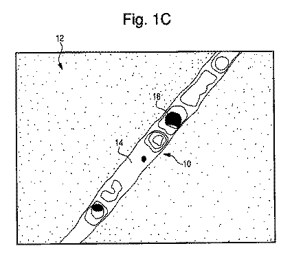
表1に示されるように、所望する結果を得るために、異なる組合せを用いることができる。これらの設定のいくつかの組合せは、最良の切り離し特性と良好な引っ張り特性を生じ、いくつかの組合せは、良好な切り離し特性と最良の引っ張り特性を生じ、そしていくつかの組合せは、良好な切り離し特性と良好な引っ張り特性を生じる。しかしながら、レーザ出力、デューティサイクル、スキャン速度及び周波数の設定の組合せの大部分は、切り離し特性が不満足であるか、引っ張り特性が不満足であるかのいずれかの点により、十分な結果が得られない。 As shown in Table 1, different combinations can be used to obtain the desired result. Some combinations of these settings produce the best detachability and good tensile properties, some combinations produce the best detachment properties and best tensile properties, and some combinations provide good detachment properties. Results in good tensile properties. However, most combinations of laser power, duty cycle, scan speed, and frequency settings do not provide satisfactory results due to either unsatisfactory detachment characteristics or unsatisfactory tensile characteristics. .
表1に最もよく示されるように、レーザ出力は、個々の動作パラメータに関連して制御され得る。しかしながら、その替わりとしてレーザ出力は、単位時間当たりのエネルギー密度(EDPUT:Energy Density Per Unit Time)に関連して制御されてもよい。EDPUTは、所定の時間内に所定の領域に適用される出力の量を規定するパラメータである。EDPUTはワット・秒/mm3にて、又は、レーザスポット移動速度(mm/s)及びレーザスポット領域(mm2)により除算される連続的なレーザ出力(ワット)を表す他の類似の単位にて表現できる。EDPUTは、出力、デューティサイクルもしくは所与の出力における被加工物に対するレーザの速度を変更することにより、又は他のパラメータにより、及びパラメータの組合せにより制御可能である。EDPUTは、所望する結果を繰り返し可能な態様で得るために一定範囲内に留まるように制御可能である。EDPUT決定についての更なる詳細は、特許文献1に開示されており、参照することによりその開示をここに包含するものとする。 As best shown in Table 1, the laser power can be controlled in relation to individual operating parameters. However, as an alternative, the laser output may be controlled in relation to the energy density per unit time (EDPUT: Energy Density Per Unit Time). EDPUT is a parameter that defines the amount of output applied to a given area within a given time. EDPUT is in watts / second / mm 3 or other similar units representing continuous laser power (watts) divided by laser spot moving speed (mm / s) and laser spot area (mm 2 ) Can be expressed. The EDPUT can be controlled by changing the speed of the laser relative to the workpiece at power, duty cycle or a given power, or by other parameters and combinations of parameters. The EDPUT can be controlled to stay within a certain range to obtain the desired result in a repeatable manner. Further details on EDPUT determination are disclosed in US Pat. No. 6,099,077, the disclosure of which is hereby incorporated by reference.
例えば、容易切り離し材料を作製するためには、レーザの速度が10〜50m/sでよく、レーザのスポット直径が0.05〜0.3mmでよく、レーザの出力が1,000〜5,000Wでよい。これにより、EDPUT範囲は0.28〜254.77ワット・秒/mm3となる。これらを異なるパラメータに替えてもなおEDPUTを同じ値にできることに注意すべきである。しかしながら、同じEDPUTの値は、必ずしも同じ切り離し特性及び引っ張り特性をもたらすとは限らない。 For example, in order to produce an easily cut material, the laser speed may be 10 to 50 m / s, the laser spot diameter may be 0.05 to 0.3 mm, and the laser output is 1,000 to 5,000 W. It's okay. This results in an EDPUT range of 0.28 to 254.77 Watt · sec / mm 3 . It should be noted that EDPUT can still be the same value even if these are replaced with different parameters. However, the same EDPUT value does not necessarily result in the same disconnect and tensile properties.
動作パラメータの広範な変化が、本発明の範囲の下で考慮されることにも注意すべきである。動作パラメータにおける僅かな変化が、異なる結果をもたらす場合もある。材料のタイプ、表面特性及び厚さが、本明細書で説明した実施例の値からの変化をもたらす一方で、それでもなお本発明の範囲内にあるであろう。本発明は、孔サイズ、孔の間隔及び孔の数を制御する必要性を排除する。その替わりに、レーザが材料ウェブの表面をスキャンすることにより、容易に切り離せると同時に十分な引っ張り強度を保持するように材料を変えることができる。実施例では、直線について説明されかつ示されるが、波線、曲線又はジグザグ線を含む他のタイプの線についても適用できる。 It should also be noted that a wide range of operating parameters are considered under the scope of the present invention. Slight changes in operating parameters may give different results. While the material type, surface properties, and thickness provide variations from the example values described herein, they will still be within the scope of the present invention. The present invention eliminates the need to control the hole size, hole spacing and number of holes. Instead, the laser can scan the surface of the material web to change the material so that it can be easily separated while maintaining sufficient tensile strength. In the examples, straight lines are described and shown, but are applicable to other types of lines including wavy lines, curved lines or zigzag lines.
図1〜図9Bは、動作パラメータを変えられるレーザを用いて形成された切り離し線を有する材料を示している。これらの実施例の全てにおいて、3,000ワットCO2レーザが用いられた。図1〜図8Cは、OPPテープにレーザエッチングされた線を示している。OPPテープは、二軸配向ポリプロピレンフィルムテープであり、通常、溶媒ベースのアクリル系接着剤をコーティングされている。OPPテープのいずれの実施例も、J.V. Convertg Companyにより製造された型番OPP-22CCであり、その仕様はここに参照することにより包含するものとする。このテープは30μm二軸配向ポリプロピレンから作製され、厚さ2.2ミル(1ミル=1000分の1インチ)であり、通常の引っ張り強度は20ポンド/インチである。図9A及び図9Bは、クラフトテープにレーザエッチングされた線を示している。クラフトテープの実施例は、J.V. Convertg Companyにより製造された型番FPPT-01であり、その仕様はここに参照することにより包含するものとする。このテープは、天然/合成ゴムブレンド接着剤によりコーティングされたクラフト平背面紙から作製され、厚さ7ミルであり、引っ張り強度は36ポンド/インチである。 FIGS. 1-9B show a material having a severing line formed using a laser with variable operating parameters. In all of these examples, a 3,000 watt CO 2 laser was used. 1-8C show lines laser etched on the OPP tape. The OPP tape is a biaxially oriented polypropylene film tape and is usually coated with a solvent-based acrylic adhesive. All examples of OPP tape are model number OPP-22CC manufactured by JV Convertg Company, the specification of which is incorporated herein by reference. The tape is made from 30 μm biaxially oriented polypropylene, is 2.2 mils thick (1 mil = 1 / 1000th of an inch), and has a typical tensile strength of 20 pounds / inch. 9A and 9B show lines laser etched on the craft tape. An example of a kraft tape is model number FPPT-01 manufactured by JV Convertg Company, the specification of which is hereby incorporated by reference. This tape is made from Kraft flat backing paper coated with a natural / synthetic rubber blend adhesive, is 7 mils thick and has a tensile strength of 36 pounds / inch.
エッチングされたクラフトテープ及びOPPテープは、ここでは実施例として示され、限定されるものではない。広範で多様なテープ、例えば医療用、電子用、透明、オフィス用、ダクト用、カーペット用、ベルクロ(Velcro(登録商標))、アクリル系、非接着性等を、容易切り離し材料を形成するためにレーザエッチングすることが可能である。同様に、レーザエッチング線を、広範で多様な材料ウェブ、例えば紙、プラスチック、皮革、金属箔等における穿孔の替わりに用いることが可能である。各材料について、容易に切り離し可能でありかつ使用中は十分な引っ張り強度を保持するという最終製品の最適バランスを実現するために動作パラメータを変更することができる。多様なタイプのレーザを用いることができるとともに、なおかつ所望する結果を得られる。例えば、200ワットレーザすなわちイットリウムアルミニウムガーネット(Yag)レーザを用いることもできる。Yagレーザを用いると、非常に小さいビーム直径が得られるので、所与の用途に有用である。 Etched kraft tape and OPP tape are shown here as examples and are not limiting. A wide variety of tapes, such as medical, electronic, transparent, office, duct, carpet, velcro, acrylic, non-adhesive, etc., to form an easy-release material Laser etching is possible. Similarly, laser etched lines can be used in place of perforations in a wide variety of material webs such as paper, plastic, leather, metal foil, and the like. For each material, the operating parameters can be changed to achieve an optimal balance of the final product that is easily separable and retains sufficient tensile strength during use. Various types of lasers can be used and still achieve the desired results. For example, a 200 watt laser or yttrium aluminum garnet (Yag) laser may be used. Using a Yag laser is useful for a given application because very small beam diameters are obtained.
図1A〜図1Cは、OPPテープ12にエッチングされた線10を示している。実施例においては、線10は、3,000ワットレーザを出力40%、デューティサイクル60%、スキャン速度20m/s及び周波数60kHzで用いて形成された。図1Aは、光学顕微鏡(OSM)により観察されたテープ12を示している。線10は、テープ12の表面がレーザにより部分的に貫かれた領域14を含む。図1B及び図1Cは、走査型電子顕微鏡(SEM)によりさらに詳細に観察した同じ線10を示している。図1B及び図1Cに最もよく示されるように、レーザは、領域16にてテープを貫通している。線10は、レーザの1回の通過で形成され、異なる部分14、16における深さの変化は、レーザの制御パラメータによる。線10は、良好な切り離し特性と最良の引っ張り特性をもつテープ12をもたらす。
1A-1C show a
図2は、光学顕微鏡により観察された材料22のウェブにエッチングされた線20を示す。実施例においては、線20は、出力35%、デューティサイクル60%、スキャン速度20m/s及び周波数20kHzで動作するレーザを用いて形成された。線20は、完全にエッチングすることなく材料22の表面を貫通している。これにより、材料22にクレータ24が形成されている。図2に最もよく示されるように、クレータ24は、レーザの制御パラメータにより得られるそれらの深さに沿って形状が変化している。クレータ24の形状により、線20の他の特性と併せて、片寄りなく線20に沿って容易に切り離すことができなおかつ十分な引っ張り強度を有する材料22が得られる。従って、線20は良好な切り離し特性と最良の引っ張り特性をもたらす。
FIG. 2 shows a
図3は、光学顕微鏡により観察された材料32のウェブにエッチングされた線30を示している。実施例においては、線30は、出力45%、デューティサイクル60%、スキャン速度25m/s及び周波数20kHzで動作するレーザを用いて形成された。これらのパラメータは、線30の長さに沿ったクレータ34を形成する。図2と同様であるが、線30のクレータ34は、図2のクレータ24よりもわずかに、さらに離間している。これは、レーザのスキャン速度が増している一方、周波数が同じに留まっていることによる。わずかな違いはあるが、線20、30の双方とも、容易に切り離し可能である一方、十分な引っ張り強度をもつ所望の品質を呈する。
FIG. 3 shows a
図4に類似の線40が示されている。この実施例においては、レーザは、出力65%、デューティサイクル60%、スキャン速度25m/s及び周波数10kHzに設定された。この場合も、線40は、材料42を完全に貫通することなくエッチングされた。この設定は、図2及び図3の線20、30と同様に、深さに沿って形状が変化するクレータ44を形成する。線20及び30では良好な切り離し特性と最良の引っ張り特性が得られる一方、線40では最良の切り離し特性と良好な引っ張り特性が得られる。従って、材料を切り離す機能は向上したが、引っ張り強度は低下した。
A
図5A〜図5Cは、材料52にエッチングされた線50を示す。図5Aは、光学顕微鏡により観察された線50を示す一方、図5B及び図5Cは走査型電子顕微鏡により観察された線50を示す。この実施例においては、図5Aの線50は、出力40%、デューティサイクル60%、スキャン速度30m/s及び周波数20kHzにレーザを設定して形成された。線50は、深さに沿って側面形状が変化するクレータ54を有する。これらのクレータ54は、図5B及び図5Cの走査型電子顕微鏡の画像では、より近接して現れている。線50では、良好な切り離し特性と最良の引っ張り特性を有する材料52が得られる。
5A-5C show a
上述した通り、動作パラメータにおける変更は、材料において異なる表面形状を生じることとなる。図6に最もよく示されるように、出力55%、デューティサイクル50%、スキャン速度20m/s及び周波数60kHzに設定されたレーザにより形成された線60は、大きなクレータや孔が無く、ほとんど直線の溝を生じる。この溝64の中央は、側縁部分66よりも深くなっており、レーザのパラメータに依存して下方への曲面又は斜面となっている。線60は、他の線とは異なるが、なおかつ最良の切り離し特性と良好な引っ張り特性をもつ所望する特性を備えている。
As described above, changes in operating parameters will result in different surface shapes in the material. As best shown in FIG. 6, the
図1A〜図6に最もよく示されるように、幾つかの全く異なる表面形状が得られ、かつ、本発明により予期された必要とする切り離し性及び引っ張り強度を備えた材料を形成することができる。本発明を実行する場合、正確な表面特性に着目する必要はないが、所与の表面形状は、特定の材料又は用途において有利となり得る。このことは、本開示を読んだ当業者には自明であろう。 As best shown in FIGS. 1A-6, several completely different surface shapes can be obtained and a material with the required detachability and tensile strength anticipated by the present invention can be formed. . When practicing the present invention, it is not necessary to focus on precise surface properties, but a given surface shape can be advantageous in a particular material or application. This will be apparent to those skilled in the art after reading this disclosure.
異なる動作パラメータは、完全に異なる特性を現す類似の表面形状を形成することができる。図7A〜図7Cは、出力60%、デューティサイクル30%、スキャン速度20m/s、及び周波数20kHzに設定されたレーザによりエッチングされた線70を示している。図7Aは、光学顕微鏡により観察された線70を示し、一方、図7B及び図7Cは、走査型電子顕微鏡により観察された線70を示す。図7Aの線70は、表面を貫通しているが材料72は貫通していないクレータ74を含む。図8A〜図8Cは、溝86の内側に位置する多数のクレータ84を有する線80における類似の表面形状を示している。線80は、出力60%、デューティサイクル60%、スキャン速度30m/s、及び周波数60kHzに設定されたレーザによりエッチングされた。図8Aは、光学顕微鏡により観察された線80を示し、一方、図8B及び図8Cは、走査型電子顕微鏡により観察された線80を示す。線70及び線80の表面形状は類似しているが、線80は引っ張り強度が劣っている。従って、線80を形成するためにデューティサイクルと周波数を増したことにより、容易に切り離され過ぎるために通常の使用に適さない材料となった。それに対し、線70は、通常の取り扱いを維持しつつも、所望するときは容易に切り離せる特性である。よって、良好な引っ張り特性と良好な切り離し特性の双方を得る結果を決定するものは、必ずしも、従来の穿孔において通常依存していた個々の孔又は表面要素の数、間隔及び大きさではない。
Different operating parameters can form similar surface shapes that exhibit completely different properties. FIGS. 7A-7C show a
図9A及び図9Bは、3,000ワットCO2レーザを用いてクラフトテープ92にエッチングされた線90を示している。レーザは、出力40%、デューティサイクル60%、スキャン速度20m/s、及び周波数60kHzに設定された。図9Bに最もよく示されるように、レーザは、テープ92の表面を部分的に貫いて、クレータ94を形成する。
9A and 9B show a
図10〜図21に最もよく示されるように、更なるレーザ設定の例について結果を予測するためにコンピュータモデリングも行った。切り離し容易でかつ十分な引っ張り強度を保持する材料を形成するべくレーザ出力、スキャン速度、周波数及びデューティサイクルの許容可能な組合せを決定するために、コンピュータによるD−最適実験計画設計の実験技術が用いられた。コンピュータによるD−最適実験計画設計の実験は、設計を評価するために統計的基準に基づくアルゴリズムを用いる。各実験後、切り離し特性及び引っ張り特性についてそれぞれ1〜5の評価付けをされ、1が最低で5が最高とした。実験は繰り返し行い、先に行った各々の実験結果により後続する実験のパラメータを決定した。異なるデューティサイクルについての複数のポイントが、3,000ワットCO2レーザの最大レーザ出力の30%〜70%の間の出力レベル(P)に亘って実験された。異なるグラフは、m/sで計測された異なるスキャン速度(SS)及びkHzで計測された異なる周波数を表している。 As best shown in FIGS. 10-21, computer modeling was also performed to predict results for additional laser setting examples. Computer-aided D-optimal design design experimental techniques are used to determine acceptable combinations of laser power, scan speed, frequency and duty cycle to form a material that is easy to detach and retains sufficient tensile strength. It was. Computer D-optimal experimental design design experiments use algorithms based on statistical criteria to evaluate the design. After each experiment, the detachment and tensile properties were rated 1-5 respectively, with 1 being the lowest and 5 being the highest. The experiment was repeated, and the parameters of the subsequent experiment were determined based on the results of the previous experiments. A plurality of points for different duty cycles were experimentally across the output level (P) of between 30% to 70% of the maximum laser power of 3,000 watts CO 2 laser. The different graphs represent different scan speeds (SS) measured in m / s and different frequencies measured in kHz.
図10〜図21は、実験されたパラメータにおける応答曲線を表している。図10〜図21を比較することにより、切り離し特性の評価において絶対的に最高のレーザ設定の組合せは、引っ張り特性の評価において絶対的に最低となる傾向があり、かつ、逆も同様であることが明らかである。従って、切り離し特性と引っ張り特性の間の最良のバランスを得るレーザ設定の組合せを見極めるために、切り離し特性と引っ張り特性に対して均等の重みを割り当てて最適化を行った。しかし、望ましい場合には、用途及び材料に応じて切り離し特性と引っ張り特性の評価において異なる重み付けを行うこともできる。 10 to 21 show the response curves for the parameters studied. By comparing FIGS. 10-21, the combination of the absolute best laser settings in the evaluation of the detachment characteristics tends to be the absolute lowest in the evaluation of the tensile characteristics and vice versa. Is clear. Therefore, optimization was performed by assigning equal weights to the detachment and tensile properties in order to determine the combination of laser settings to obtain the best balance between detachment and tensile properties. However, if desired, different weightings can be applied in the assessment of the separation and tensile properties depending on the application and material.
この場合、最適設定が、実験されたOPPテープについて4.35の予測された切り離し特性評価と4.48の予測された引っ張り特性評価を得るように導出された。これを得るためのレーザ設定の例は、(可能な3,000ワット出力のうち)出力45%、デューティサイクル85%、スキャン速度20m/s、及び周波数10kHzと決定された。しかし、これらの実験は、実験された特定のテープについてこの最適に近い良好な結果を生成する幾つかの他のレーザ設定の組合せがあることを明らかとした。 In this case, an optimal setting was derived to obtain a predicted release property rating of 4.35 and a predicted tensile property rating of 4.48 for the experimental OPP tape. Examples of laser settings to obtain this were determined with an output of 45% (out of a possible 3,000 watt output), a duty cycle of 85%, a scan speed of 20 m / s, and a frequency of 10 kHz. However, these experiments revealed that there are several other laser setting combinations that produce good results near this optimum for the particular tapes that were tested.
出力3,000ワットとスキャン速度50m/sの性能をもつレーザにより、さらに別の実験を行った。HenkelCorporationの厚さ3ミル(0.003インチ)のHP260 OPPテープ及びShurtapeの厚さ6.2ミル(0.0062インチ)のFP96 Kraftテープの2つの異なるテープがこれらの実験に用いられた。この場合も、切り離し特性と引っ張り特性の最良のバランスを生じる出力、スキャン速度、周波数及びデューティサイクル等のレーザ変数の組合せが存在することが判明した。表2は、HP260テープについての最良の結果を生じるレーザ設定の例を示し、そして、表3は、Kraftテープについての最良の結果を生じるレーザ設定の例を示している。これらの結果は、限定することを意味しておらず、他の変数を用いても本発明の範囲内に含まれる場合もあることを注記する。表2及び表3に示された結果では、50m/sのスキャン速度であっても良好な結果が得られることが最も重要である。このことは、切り離し容易な製品を作製するためのコストに対して大きな経済的影響をもたらす。なぜなら、多くのレーザシステムは、例えば4m/s又はそれ未満の著しく限定されたスキャン速度だからである。従って、多様な材料において、従来方法における処理時間を格段に低減することが可能である。
A further experiment was performed with a laser having an output of 3,000 watts and a scanning speed of 50 m / s. Two different tapes were used in these experiments: a
実施例では、60インチのフィールドサイズをもつ3,000ワットレーザが、移動するOPPテープ材料の60インチウェブに、50m/sのスキャン速度で線をエッチングする。別の例として、20インチのフィールドサイズをもつ3つの高出力レーザが、同じ移動するウェブに高速で線をエッチングできる。これと比べて、同じ材料に対する従来のレーザドリル又は穿孔では、10〜15個の低出力レーザが4m/sを超えない各レーザのスキャン速度となるように要求される点で、全く制限される。 In an embodiment, a 3,000 watt laser with a 60 inch field size etches a line onto a 60 inch web of moving OPP tape material at a scan rate of 50 m / s. As another example, three high power lasers with a 20 inch field size can etch lines at high speed into the same moving web. In contrast, conventional laser drilling or drilling on the same material is quite limited in that 10-15 low power lasers are required to have a scan speed of each laser not exceeding 4 m / s. .
実施例では、ガルバノメータ駆動ミラーにより材料の表面を横切ってレーザビームを移動させることにより、エッチングされた線が形成される。図22に最もよく示されるように、レーザ111は、コンピュータ制御されたミラーシステムに向けてビーム112を生成する。
In an embodiment, etched lines are formed by moving the laser beam across the surface of the material with a galvanometer drive mirror. As best shown in FIG. 22,
図示されたミラーシステムは、X軸ガルバノメータ114上に装着されて駆動されるX軸ミラー113を具備する。X軸ガルバノメータ114は、回転してX軸ミラー113の回転を生じるように構成されている。レーザビーム112がX軸ミラー113に入射する間のX軸ミラー113の回転により、レーザビーム112がX軸に沿って動くこととなる。数値制御コンピュータ115は、X軸ガルバノメータ114によるX軸ミラー113の回転を制御する駆動源116の出力を制御する。レーザビーム112は、X軸ミラー113により逸らされ、Y軸ガルバノメータ118上に回転可能に装着されたY軸ミラー117に向けられる。Y軸ガルバノメータ118は、回転してY軸ミラー117の回転を生じるように構成されている。Y軸ミラー117の回転は、Y軸に沿ったY軸ミラー117上に入射するレーザビーム112の動きを生じさせる。数値制御コンピュータ115は、Y軸ガルバノメータ118の回転を制御するためにY軸ガルバノメータ118に供給される駆動源116の出力を制御する。
The illustrated mirror system includes an
当業者であれば、凹レンズ、凸レンズ、焦点レンズ、円筒レンズ、ミラー、スプリッタ、コンバイナ等の別の光学部品及びレンズを、ミラーの前又は後に導入できることは、理解できるであろう。これらの光学部品の追加は、各用途の必要に応じて、レーザの特性及びエッチング動作のパラメータを調整するために用いることができる。 One skilled in the art will appreciate that other optical components and lenses such as concave lenses, convex lenses, focus lenses, cylindrical lenses, mirrors, splitters, combiners, etc. can be introduced before or after the mirror. The addition of these optical components can be used to adjust the characteristics of the laser and the parameters of the etching operation as needed for each application.
この装置はさらに、テーブル若しくはコンベア等の固体基板、又は流動体ベッドでよい作業面120を具備する。加えて、作業面120はレーザ111のちょうど作業領域となり、そこでは材料121のウェブが、例えば1つのスプールから別のスプールへと特別な支持構造なしで横切って動く。材料(すなわち作業片)121は、作業面120上に置かれる。材料121はエッチングされる表面122を有する。レーザビーム112は、ミラー113、117により材料121の表面122に対して向けられる。通常、レーザビーム112は、表面122にほぼ垂直に向けられるが、レーザビーム112と表面122の間の角度を約45°〜135°の範囲で調整することにより異なる製品が得られる。材料121の表面122に接触するレーザビーム112の相対的移動により、表面122上にエッチングされた線123を生じる。ミラー113、117の動作及びタイミングは、線123をエッチングするために数値制御コンピュータ115により制御される。本命最初で参照するように、相対的移動には、材料121が静置したままでのレーザビーム112の移動(例えばミラーシステムを用いる)、レーザビーム112が静置したままでの材料121の移動、又は、例えば弾み連続印刷プロセスでのレーザエッチングにおけるレーザビーム112と材料121の同時移動の組合せが含まれる。材料121が移動すると、レーザビーム112は、ガルバノミラー113、117の軸に沿った動きにより周期的形態で各部分を単純にエッチングする。レーザビーム112は、材料121が移動し続けていながら、なおかつ直線が材料にエッチングされるように制御可能である。さらに、レーザビーム112は、材料121を横切って連続的移動を行ってもよい。レーザビーム112の連続的スキャンが、常に連続的な線を生じるわけではないことに注意すべきである。レーザ111のデューティサイクル及び周波数は、レーザビーム112が材料121の所定の部分にはほとんど又は全く影響を及ぼさず、それにより連続的にスキャンされるレーザビーム112が不連続な線を生じるように制御可能である。
The apparatus further comprises a
材料121の単一シートが示されているが、本発明は、作業面120を横切って動く材料のウェブを用いて理想的に実行される。材料121の幅に応じて、線123を形成するために1つより多いレーザ111を用いてもよい。1つより多い方向の線、例えば垂直な線と水平な線が必要な場合、追加のレーザ112を用いてもよい。もちろん、単一の移動可能なレーザを、双方の線を形成するために用いてもよい。さらに、材料121のウェブは、材料121の固体シートでもよく、材料121の個々の帯片からなってもよい。例えば、材料121は、個々の幅に既に切断されている個別の複数ロールでもよい。これらのロールは、単一ウェブ上に載置され、1又は複数のレーザ111の作業面120を横切って動かされる。これらの個別のロールは、必要に応じて同じ幅でも異なる幅でもよい。別の例として、材料121の単一シートの大きなウェブを作業面120を横切って動かし、その後で、同じ幅か異なる幅をもつ材料121の個別のシートに分割してもよい。材料121の単一シートを分割することは、線をレーザエッチングした同じレーザ111により行ってもよく、又は、別のレーザにより行ってもよい。本発明を接着剤テープに対して実施する場合、テープ背面に接着剤を塗布する前又は後のいずれにおいても、ここで記載した処理を行うことができることに注意すべきである。
Although a single sheet of
レーザは、図22に示した一例以外の他の有効な手段により材料をスキャンすることができる。この例は、X−Y形式でのレーザ111の移動、X−Y形式での作業面120の移動、又は2つの組合せを行うことを含む。例えば、リードねじ及びリニア駆動モータによる作業面120及びレーザ111の移動が実現可能であるが、他の適切な方法も許容できる。レーザ111の材料121からの距離は、レーザ111又は作業面120のいずれかを動かすことにより調整可能である。このシステムはまた、レーザの作業領域に射出される不活性ガスを含むタンクを備えてもよい。
The laser can scan the material by other effective means other than the example shown in FIG. Examples of this include moving the
レーザを制御するためのさらに別のシステム及び方法は、特許文献2に開示されており、参照することによりその内容を包含するものとする。 Yet another system and method for controlling the laser is disclosed in US Pat.
ウェブの供給速度及びレーザの動作パラメータは、異なる材料に対して最適な結果をもたらすように変更可能である。これらの変数は、制御装置(図示せず)により調整可能である。種々の実施例においては、制御装置は数値制御コンピュータシステムであるが、いずれのタイプのコンピュータシステムを用いてもよい。レーザ制御装置は、ミラー制御装置115と同じでもよく、又は、別個の専用ユニットとしてもよい。所望するパラメータは、ユーザによりシステムに入力されてもよく、予め記憶されたテーブルから選択されてもよく、又は、材料特性及び所望する最終製品に関連する変数の組に基づいて直接計算されてもよい。C、Java(登録商標)、Fortran等、制御装置をプログラムするために用いられるいかなるタイプのプログラミング言語を用いてもよい。制御装置をプログラミングするプロセスは、ローカルに又はネットワークを介して実行可能である。
The web feed rate and laser operating parameters can be varied to provide optimal results for different materials. These variables can be adjusted by a control device (not shown). In various embodiments, the control device is a numerically controlled computer system, although any type of computer system may be used. The laser control device may be the same as the
種々の実施例においては、レーザ出力、デューティサイクル、スキャン速度及び周波数が制御されかつ材料の形態が無視された場合にも、許容可能な結果が得られる。一例では、本発明はまた、特別な材料のためのこれらの変数を最適化する方法を目的とする。数値試験の後、D−最適実験計画設計を用いた統計的解析が行われた。D−最適実験計画設計は、多くの変数を効率的に探査することを可能とする。非制御変数は平均化され、独立変数の間の相互作用及び曲線の影響は容易に解析され、望ましくない又は情報の少ない実験は排除される。D−最適実験計画設計を実行するプログラムの一例として、Haller Information TechnologySystemによる"Experimental Design Optimizer"がある。独立変数及びそれらのレベルは、ソフトウェアプログラムに入力される。出力は、統計的に重要な結果、実験の順序及び各独立変数のレベルを得るために実行する実験の特定の数字である。この場合、従属変数は、切り離し特性と引っ張り特性の評価1〜5である。独立変数は、レーザ出力、スキャン速度、デューティサイクル及び周波数である。
In various embodiments, acceptable results are also obtained when laser power, duty cycle, scan speed and frequency are controlled and material morphology is ignored. In one example, the present invention is also directed to a method of optimizing these variables for a particular material. After numerical testing, statistical analysis using D-optimal experimental design was performed. D-optimal experimental design allows many variables to be explored efficiently. Uncontrolled variables are averaged, interactions between independent variables and the effects of curves are easily analyzed, and unwanted or less informative experiments are eliminated. An example of a program for executing D-optimal experiment design is “Experimental Design Optimizer” by Haller Information Technology System. Independent variables and their levels are entered into the software program. The output is a specific number of experiments performed to obtain statistically significant results, the order of experiments and the level of each independent variable. In this case, the dependent variables are
D−最適実験計画設計を実行した後、これらの実験から得たデータが、回帰モデルを用いて解析される。回帰解析は、レーザパラメータの1つが変更されかつ他は固定されたときに切り離し特性及び引っ張り特性の評価がどのように変わるかを理解することに役立つ。使用可能な回帰方法の幾つかの例は、線形回帰、通常の最小二乗回帰、又はノンパラメトリック回帰形態がある。回帰解析を実行するプログラムの例は、Haller Information TechnologySystemによる"Multiple Correlation Analysis"がある。統計的に設計された実験から得たデータは、このソフトウェアに入力される。その後、プログラムは、切り離し強度及び引っ張り強度をレーザ出力、スキャン速度、デューティサイクル、周波数及びこれら全ての相互作用に量的に関係づける種々の異なる回帰モデルを生成することができる。 After performing the D-optimal experiment design, the data obtained from these experiments is analyzed using a regression model. Regression analysis helps to understand how the evaluation of detachment and tensile properties changes when one of the laser parameters is changed and the other is fixed. Some examples of regression methods that can be used are linear regression, ordinary least squares regression, or nonparametric regression forms. An example of a program that executes regression analysis is "Multiple Correlation Analysis" by Haller Information Technology System. Data obtained from statistically designed experiments is input to this software. The program can then generate a variety of different regression models that quantitatively relate detachment strength and tensile strength to laser power, scan speed, duty cycle, frequency, and all these interactions.
最後に、切り離し特性と引っ張り特性の最良バランスのための最適プロセス設定が、数学的最適化により決定できる。最適化を実行するプログラムの例は、Haller Information TechnologySystemによる"Multiple Property Optimization"がある。線形回帰から決定された相関方程式は、このソフトウェアに対する入力として機能する。切り離し特性及び引っ張り特性の評価に対して種々の重みが割り当てられ、ソフトウェアは切り離し特性と引っ張り特性の間の最良バランスのためのレーザ出力、スキャン速度、デューティサイクル及び周波数を決定する。この方法においては、多様な材料において所望する品質を得るために十分なレーザパラメータを導出することができる。 Finally, the optimal process settings for the best balance of detachment and tensile properties can be determined by mathematical optimization. An example of a program that executes optimization is “Multiple Property Optimization” by Haller Information Technology System. The correlation equation determined from linear regression serves as input to this software. Various weights are assigned to the assessment of the separation and tensile properties, and the software determines the laser power, scan speed, duty cycle and frequency for the best balance between the separation and tensile properties. In this way, sufficient laser parameters can be derived to obtain the desired quality in a variety of materials.
上述した本発明の実施例は、図示の目的で提示した。本発明を開示された精細な形態に限定するものでも、他を排除するものでもない。上述の技術に照らして自明の修飾又は変形が可能である。例えば、他の材料、変数及び数値を用いることができる。上述した実施例は、本発明の原理及びその実用的な用途を示すために選択されたもので、それにより当業者であれば種々の実施例及び種々の改変において、ここに開示した原理に従う限りにおいて、特定に用途に適した本発明を最良に利用できるものである。このように、本発明の主旨及び範囲から逸脱することなく上述した本発明における変更は可能である。さらに、一実施例の特徴又は構成要素を別の実施例で適用してもよい。よって、本発明は、そのような改変及び変形を全て包含するよう意図されている。 The above-described embodiments of the present invention have been presented for purposes of illustration. It is not intended to limit the invention to the precise form disclosed, nor to exclude others. Obvious modifications or variations are possible in light of the above-described techniques. For example, other materials, variables, and numerical values can be used. The above-described embodiments have been selected to illustrate the principles of the invention and its practical application, so that one skilled in the art can follow the principles disclosed herein in various embodiments and various modifications. Therefore, the present invention suitable for a specific application can be best utilized. Thus, the above-described changes in the present invention can be made without departing from the spirit and scope of the present invention. Furthermore, features or components of one embodiment may be applied in another embodiment. Accordingly, the present invention is intended to embrace all such alterations and modifications.
111 レーザ
112 レーザビーム
113 X軸ミラー
114 X軸ガルバノメータ
115 数値制御コンピュータ
116 駆動源
117 Y軸ミラー
118 Y軸ガルバノメータ
120 作業面
121 材料
122 表面
123 線
DESCRIPTION OF
Claims (60)
第1の主面と、
前記第1の主面の反対側に位置する第2の主面と、
一方の前記主面上のレーザエッチングされた線と、を有し、
前記シート材料は、力が加わることにより前記レーザエッチングされた線に沿って分離することとなる、シート材料。 A sheet material,
A first main surface;
A second main surface located on the opposite side of the first main surface;
A laser-etched line on one of the major surfaces;
The sheet material is separated along the laser-etched line when a force is applied.
・前記第1及び第2の主面を完全に貫通する部分
・前記主面を部分的に貫く部分
・前記主面を貫通しない部分 The sheet material according to claim 1, wherein the laser-etched line is composed of at least two of the following.
-A portion that completely penetrates the first and second main surfaces-A portion that partially penetrates the main surface-A portion that does not penetrate the main surface
第1の主面と、
前記第1の主面の反対側に位置する第2の主面と、
一方の前記主面を横切ってレーザエッチングされ連続的にスキャンされた線と、を有し、
前記シート材料は、力が加わることにより前記レーザエッチングされ連続的にスキャンされた線に沿って分離することとなる、シート材料。 A sheet material,
A first main surface;
A second main surface located on the opposite side of the first main surface;
A laser-etched and continuously scanned line across one of the major surfaces;
The sheet material is separated along the laser-etched and continuously scanned lines when force is applied.
第1の主面と前記第1の主面の反対側に位置する第2の主面とを有するシート材料のウェブを設置するステップと、
作業領域を有するレーザを設置するステップと、
前記レーザの作業領域を横切って前記材料を動かすステップと、
前記シート材料の少なくとも一方の前記主面上に線をエッチングするために前記レーザを用いるステップと、を備えた容易切り離しシート材料の作製方法。 A method for producing an easily separating sheet material,
Installing a web of sheet material having a first major surface and a second major surface located opposite the first major surface;
Installing a laser having a work area;
Moving the material across the working area of the laser;
Using the laser to etch a line on the major surface of at least one of the sheet materials.
・前記第1及び第2の主面を完全に貫通する部分
・前記主面を部分的に貫く部分
・前記主面を貫通しない部分 26. A method of making an easy-cut sheet material according to claim 25, wherein the laser-etched lines comprise at least two of the following.
-A portion that completely penetrates the first and second main surfaces-A portion that partially penetrates the main surface-A portion that does not penetrate the main surface
第1の主面と前記第1の主面の反対側に位置する第2の主面とを有するシート材料のウェブを設置するステップと、
作業領域を有するレーザを設置するステップと、
前記レーザの作業領域を横切って前記材料を動かすステップと、
前記シート材料の少なくとも一方の前記主面上をレーザで連続的にスキャンすることにより前記主面を横切って線をエッチングステップと、を備えた容易切り離しシート材料の作製方法。 A method for producing an easily separating sheet material,
Installing a web of sheet material having a first major surface and a second major surface located opposite the first major surface;
Installing a laser having a work area;
Moving the material across the working area of the laser;
Etching a line across the main surface by continuously scanning the main surface of at least one of the sheet materials with a laser.
レーザのパラメータの少なくとも1つに対して設定値を割り当てるステップと、
前記パラメータの少なくとも1つを変更するステップと、
各変数における切り離し特性の評価と引っ張り特性の評価を決定するステップと、
切り離し特性の評価と引っ張り特性の評価の間の許容できるバランスを付与する変動幅を決定するステップと、を含む、容易切り離し材料の作製方法。 A method of making an easily detachable material having sufficient tensile strength to avoid undesired detachment during use, comprising:
Assigning a setting value to at least one of the parameters of the laser;
Changing at least one of the parameters;
Determining the evaluation of the separation characteristics and the evaluation of the tensile characteristics in each variable;
Determining a range of variation that provides an acceptable balance between evaluation of detachment properties and evaluation of tensile properties.
独立変数がレーザ動作パラメータを含みかつ従属変数が材料の切り離し特性及び引っ張り特性の評価である、実験のセットを決定するステップと、
各実験を実行するステップと、
前記実験から得たデータを解析するステップと、
十分な切り離し特性と引っ張り特性をもつレーザエッチングされた材料を形成するための適切なレーザ動作パラメータを決定するステップと、を含む
容易切り離し材料の形成方法。 A method of forming an easily cut material,
Determining a set of experiments, wherein the independent variable includes laser operating parameters and the dependent variable is an assessment of material detachment and tensile properties;
Performing each experiment; and
Analyzing the data obtained from the experiment;
Determining suitable laser operating parameters for forming a laser-etched material having sufficient release and tensile properties.
Applications Claiming Priority (3)
| Application Number | Priority Date | Filing Date | Title |
|---|---|---|---|
| US24357909P | 2009-09-18 | 2009-09-18 | |
| US61/243,579 | 2009-09-18 | ||
| PCT/US2010/049263 WO2011035112A1 (en) | 2009-09-18 | 2010-09-17 | Laser methods to create easy tear off materials and articles made therefrom |
Publications (1)
| Publication Number | Publication Date |
|---|---|
| JP2013505137A true JP2013505137A (en) | 2013-02-14 |
Family
ID=43332773
Family Applications (1)
| Application Number | Title | Priority Date | Filing Date |
|---|---|---|---|
| JP2012529925A Withdrawn JP2013505137A (en) | 2009-09-18 | 2010-09-17 | Laser method for producing easily cut material and product thereof |
Country Status (9)
| Country | Link |
|---|---|
| US (1) | US9050686B2 (en) |
| EP (1) | EP2477782A1 (en) |
| JP (1) | JP2013505137A (en) |
| CA (1) | CA2774690A1 (en) |
| CL (1) | CL2012000680A1 (en) |
| IN (1) | IN2012DN02699A (en) |
| MX (1) | MX2012003308A (en) |
| TW (1) | TW201119780A (en) |
| WO (1) | WO2011035112A1 (en) |
Families Citing this family (20)
| Publication number | Priority date | Publication date | Assignee | Title |
|---|---|---|---|---|
| DE102013104138B3 (en) * | 2013-04-24 | 2014-03-06 | Jenoptik Automatisierungstechnik Gmbh | Introducing defined line of weakness by removal of material to fibrous covering material, comprises directing pulsed laser beam to rear side of material and linearly guiding, and determining depth of score line of impingement of laser beam |
| CA2959034A1 (en) | 2014-08-27 | 2016-03-03 | Revolaze, LLC | System and method of generating a pattern or image on fabric with linear laser irradiation, fabric made by said method, and products made with said fabric |
| EP3215083B1 (en) | 2014-11-07 | 2019-08-07 | The Procter & Gamble Company | Process and apparatus for manufacturing an absorbent article using a laser source |
| US20160243653A1 (en) * | 2015-02-24 | 2016-08-25 | Electronics For Imaging, Inc. | Compensated laser cutting of labels |
| EP3429524B1 (en) | 2016-03-15 | 2019-11-20 | The Procter and Gamble Company | Methods and apparatuses for separating and positioning discrete articles |
| US10343236B2 (en) * | 2016-06-21 | 2019-07-09 | Scientific Games International, Inc. | System and method for variable perforation profiles in a stack of lottery tickets based on fold pattern |
| US10345789B2 (en) | 2016-06-21 | 2019-07-09 | Scientific Games International, Inc. | System and method for variable perforation profiles in a stack of lottery tickets |
| MX2019001777A (en) | 2016-08-19 | 2019-12-11 | Strauss Levi & Co | Laser finishing of apparel. |
| EP3363577A1 (en) * | 2017-02-17 | 2018-08-22 | Sund Birsta AB | Binding machine and method for securing a part of a binding element in a loop around one or more objects |
| EP3703898A4 (en) | 2017-10-31 | 2021-05-19 | Levi Strauss & Co. | LASER FINISHED DRAWING TOOL |
| US20190125015A1 (en) | 2017-10-31 | 2019-05-02 | Levi Strauss & Co. | Using Neural Networks in Creating Apparel Designs |
| US20190151996A1 (en) * | 2017-11-22 | 2019-05-23 | Roche Diabetes Care, Inc. | Multiple laser processing for biosensor test strips |
| EP3759580A4 (en) | 2018-02-27 | 2021-11-24 | Levi Strauss & Co. | LASER PROCESSING TOOL |
| US11313072B2 (en) | 2018-02-27 | 2022-04-26 | Levi Strauss & Co. | On-demand manufacturing of laser-finished apparel |
| CN112136167A (en) * | 2018-04-18 | 2020-12-25 | 艾利丹尼森零售信息服务公司 | Low breaking load use awareness label |
| WO2020033606A1 (en) | 2018-08-07 | 2020-02-13 | Levi Strauss & Co. | Laser finishing design tool |
| WO2020113236A1 (en) | 2018-11-30 | 2020-06-04 | Levi Strauss & Co. | Shadow neutral 3-d garment rendering |
| US11530503B2 (en) | 2019-07-23 | 2022-12-20 | Levi Strauss & Co. | Three-dimensional rendering preview in web-based tool for design of laser-finished garments |
| AT525314B1 (en) * | 2021-07-22 | 2023-10-15 | Trotec Laser Gmbh | Method for creating a perforation on a workpiece for different laser machines |
| AT526718B1 (en) * | 2021-07-22 | 2024-10-15 | Trotec Laser Gmbh | Method for producing a perforation on a workpiece for different laser machines |
Family Cites Families (46)
| Publication number | Priority date | Publication date | Assignee | Title |
|---|---|---|---|---|
| US3789421A (en) * | 1971-02-02 | 1974-01-29 | J Chivian | Binary logic apparatus |
| US3720784A (en) * | 1971-02-12 | 1973-03-13 | Bell Telephone Labor Inc | Recording and display method and apparatus |
| US4024545A (en) * | 1974-04-22 | 1977-05-17 | Mb Associates | Laser-excited marking system |
| US4629858A (en) * | 1983-12-12 | 1986-12-16 | Interface Flooring Systems, Inc. | Method for engraving carpet and carpet so engraved |
| AU597290B2 (en) * | 1985-11-14 | 1990-05-31 | Deutsches Textilforschungszentrum Nord-West E.V. | Microstructured fibre, filament and yarn |
| JPS62248681A (en) * | 1986-04-21 | 1987-10-29 | Kanzaki Paper Mfg Co Ltd | Laser image forming method |
| KR910000826B1 (en) * | 1986-11-14 | 1991-02-09 | 미쓰비시덴기 가부시기가이샤 | Method of laser marking |
| JPH0741431B2 (en) | 1987-10-07 | 1995-05-10 | 三菱電機株式会社 | Laser engraving method |
| US5171650A (en) * | 1990-10-04 | 1992-12-15 | Graphics Technology International, Inc. | Ablation-transfer imaging/recording |
| DE3916126A1 (en) | 1989-05-18 | 1990-11-22 | Kuesters Eduard Maschf | Process to print a pattern on textile fabrics - utilises irradiation to form the design |
| JPH0345578A (en) | 1989-07-12 | 1991-02-27 | Inax Corp | Glazing of multicolor design |
| US5744776A (en) * | 1989-07-14 | 1998-04-28 | Tip Engineering Group, Inc. | Apparatus and for laser preweakening an automotive trim cover for an air bag deployment opening |
| US4947022A (en) * | 1989-08-04 | 1990-08-07 | Standard Chair Of Gardner, Inc. | Laser engraving method |
| EP0413664B1 (en) * | 1989-08-18 | 1995-03-22 | Ciba-Geigy Ag | Laser-marking of plastic objects in any form by means of special effects |
| JPH0490184U (en) * | 1990-06-05 | 1992-08-06 | ||
| US5158499A (en) * | 1990-07-09 | 1992-10-27 | American National Can Company | Laser scoring of packaging substrates |
| JPH04146261A (en) * | 1990-10-04 | 1992-05-20 | Juki Corp | Automatic cutting machine for apparel |
| US5171450A (en) * | 1991-03-20 | 1992-12-15 | Nalco Chemical Company | Monitoring and dosage control of tagged polymers in cooling water systems |
| JPH05138374A (en) | 1991-11-14 | 1993-06-01 | Mitsubishi Heavy Ind Ltd | Controller for output of laser beam machine |
| JPH05228669A (en) * | 1991-12-27 | 1993-09-07 | Polymer Processing Res Inst | Method and device for manufacturing perforated web with light beam |
| GB9210521D0 (en) | 1992-05-16 | 1992-07-01 | Cadcam Punch Ltd | Cutting and embroidery process |
| JP3175463B2 (en) * | 1994-02-24 | 2001-06-11 | 三菱電機株式会社 | Laser cutting method |
| US5567207A (en) * | 1994-07-31 | 1996-10-22 | Icon, Inc. | Method for marking and fading textiles with lasers |
| GB2328895B (en) | 1994-11-07 | 1999-05-05 | Janet Stoyel | Method and apparatus for the manufacture of textiles |
| US6685868B2 (en) * | 1995-10-30 | 2004-02-03 | Darryl Costin | Laser method of scribing graphics |
| US5990444A (en) * | 1995-10-30 | 1999-11-23 | Costin; Darryl J. | Laser method and system of scribing graphics |
| US6252196B1 (en) * | 1996-10-11 | 2001-06-26 | Technolines Llc | Laser method of scribing graphics |
| DE19636429C1 (en) * | 1996-09-07 | 1997-11-20 | Jenoptik Jena Gmbh | Making weak line or desired break line with laser |
| US6140602A (en) * | 1997-04-29 | 2000-10-31 | Technolines Llc | Marking of fabrics and other materials using a laser |
| US6315202B2 (en) * | 1997-08-11 | 2001-11-13 | Technolines, Llc. | Material coding using lasers |
| US6235369B1 (en) | 1997-09-03 | 2001-05-22 | Velcro Industries B.V. | Strip-form fastening and dispensing |
| US6495237B1 (en) * | 1998-09-29 | 2002-12-17 | Technolines Llc | Denim design from laser scribing |
| US6576862B1 (en) * | 1999-01-07 | 2003-06-10 | Technolines Llc | Laser-scribing process for rubber and thermoplastic materials such as a hose |
| US6819972B1 (en) * | 1999-10-05 | 2004-11-16 | Clarence H Martin | Material surface processing with a laser that has a scan modulated effective power to achieve multiple worn looks |
| US6664505B2 (en) * | 1999-12-06 | 2003-12-16 | Technolines Llc | Laser processing of materials using mathematical tools |
| GB0014177D0 (en) * | 2000-06-09 | 2000-08-02 | Univ Warwick Science Park Limi | Packaging |
| WO2002043948A1 (en) * | 2000-12-01 | 2002-06-06 | Laser Machining, Inc. | Method for laser machining easy open, easy tear flexible packaging |
| US6807456B1 (en) * | 2001-02-09 | 2004-10-19 | Technolines, Llc | Fractal jean manufacturing |
| US20030019780A1 (en) | 2001-07-23 | 2003-01-30 | Parodi Gustavo Jose Camargo | Easy opening, re-closeable bag |
| US6753501B1 (en) * | 2001-11-03 | 2004-06-22 | Darryl Costin, Sr. | Processing of textile materials using laser beams and material sized in larger widths |
| NL1023264C2 (en) * | 2003-04-25 | 2004-10-27 | Sara Lee De Nv | Method for manufacturing a package with the aid of a foil that is at least vacuum-able when the package is filled with consumables such as, for example, coffee. |
| US7699896B1 (en) * | 2004-11-16 | 2010-04-20 | Technolines, Llc | Surface pretreatment of fabrics for laser writing applications |
| US8071912B2 (en) | 2005-11-16 | 2011-12-06 | Technolines, Lp | Engineered wood fiber product substrates and their formation by laser processing |
| EP1929912A1 (en) * | 2006-12-06 | 2008-06-11 | The Procter and Gamble Company | Tissue roll with angled perforations |
| DE102007024510B3 (en) * | 2007-05-24 | 2008-09-11 | Jenoptik Automatisierungstechnik Gmbh | Using laser to form intentional line of breakage on vehicle interior cladding covering air bag deployment system, employs matrix camera to measure and control residual cladding thickness |
| US20090159192A1 (en) * | 2007-12-21 | 2009-06-25 | Roger Bannister | Method of Manufacturing a Polypropylene Pinch Bag |
-
2010
- 2010-09-17 CA CA2774690A patent/CA2774690A1/en not_active Abandoned
- 2010-09-17 WO PCT/US2010/049263 patent/WO2011035112A1/en not_active Ceased
- 2010-09-17 MX MX2012003308A patent/MX2012003308A/en not_active Application Discontinuation
- 2010-09-17 IN IN2699DEN2012 patent/IN2012DN02699A/en unknown
- 2010-09-17 US US12/884,645 patent/US9050686B2/en not_active Expired - Fee Related
- 2010-09-17 EP EP10763502A patent/EP2477782A1/en not_active Withdrawn
- 2010-09-17 JP JP2012529925A patent/JP2013505137A/en not_active Withdrawn
- 2010-09-20 TW TW099131819A patent/TW201119780A/en unknown
-
2012
- 2012-03-16 CL CL2012000680A patent/CL2012000680A1/en unknown
Also Published As
| Publication number | Publication date |
|---|---|
| IN2012DN02699A (en) | 2015-09-04 |
| CA2774690A1 (en) | 2011-03-24 |
| US20110070390A1 (en) | 2011-03-24 |
| EP2477782A1 (en) | 2012-07-25 |
| US9050686B2 (en) | 2015-06-09 |
| WO2011035112A1 (en) | 2011-03-24 |
| MX2012003308A (en) | 2012-08-03 |
| CL2012000680A1 (en) | 2012-11-16 |
| TW201119780A (en) | 2011-06-16 |
Similar Documents
| Publication | Publication Date | Title |
|---|---|---|
| JP2013505137A (en) | Laser method for producing easily cut material and product thereof | |
| US6191382B1 (en) | Dynamic laser cutting apparatus | |
| US7988607B2 (en) | System and method for severing or perforating a web | |
| US5767480A (en) | Hole generation and lead forming for integrated circuit lead frames using laser machining | |
| DE602004005762T2 (en) | Method for controlling a cutting and creasing machine | |
| US20120263904A1 (en) | Laser methods to create easy tear-off materials and articles made therefrom | |
| US6190297B1 (en) | Apparatus for cutting and creasing sheet material | |
| CN201524876U (en) | A laser slicing and drilling equipment for rubber paste production | |
| JP2015054495A (en) | Label paper processing apparatus | |
| CN105215556A (en) | The new technology that laser cuts film is carried out to the various films that crystal column surface pastes | |
| HUE031310T2 (en) | Method and tool unit for the adjustment of the tool unit | |
| US11045908B2 (en) | Piercing workpieces by a laser beam and an associated laser processing machine | |
| US10974346B2 (en) | Laser cutting method and machine, and automatic programing apparatus | |
| CN106271058B (en) | Technique of the laser cutting less than plate thickness diameter circular aperture is carried out on plank | |
| JP2009297770A (en) | Method of working edge of blade, blade member, method of manufacturing blanking die, and blanking die | |
| US20240359261A1 (en) | Method for creating a producing on a workpiece for various laser devices | |
| CN110677993A (en) | Method for keeping same cutting characteristic during cutting of copper-clad ceramic substrate | |
| JP5957824B2 (en) | Processing system | |
| JPH01289697A (en) | Paper cutter | |
| CN109956661B (en) | Scribing method and scribing apparatus for bonded substrate | |
| JP6900106B2 (en) | Label manufacturing equipment and manufacturing method | |
| JP2024019565A (en) | punching device | |
| CN210161316U (en) | Adhesive tape punching mechanism for cutting material pulling machine | |
| JP2009291865A (en) | Method of manufacturing trimming die and trimming die | |
| JP2003261345A (en) | Method for cracking rigid brittle plate |
Legal Events
| Date | Code | Title | Description |
|---|---|---|---|
| A300 | Application deemed to be withdrawn because no request for examination was validly filed |
Free format text: JAPANESE INTERMEDIATE CODE: A300 Effective date: 20131203 |