JP2013187456A - Waterproof structure - Google Patents
Waterproof structure Download PDFInfo
- Publication number
- JP2013187456A JP2013187456A JP2012052913A JP2012052913A JP2013187456A JP 2013187456 A JP2013187456 A JP 2013187456A JP 2012052913 A JP2012052913 A JP 2012052913A JP 2012052913 A JP2012052913 A JP 2012052913A JP 2013187456 A JP2013187456 A JP 2013187456A
- Authority
- JP
- Japan
- Prior art keywords
- opening
- housing
- lens
- waterproof structure
- wall
- Prior art date
- Legal status (The legal status is an assumption and is not a legal conclusion. Google has not performed a legal analysis and makes no representation as to the accuracy of the status listed.)
- Pending
Links
Images


Classifications
-
- H—ELECTRICITY
- H05—ELECTRIC TECHNIQUES NOT OTHERWISE PROVIDED FOR
- H05K—PRINTED CIRCUITS; CASINGS OR CONSTRUCTIONAL DETAILS OF ELECTRIC APPARATUS; MANUFACTURE OF ASSEMBLAGES OF ELECTRICAL COMPONENTS
- H05K5/00—Casings, cabinets or drawers for electric apparatus
- H05K5/06—Hermetically-sealed casings
-
- H—ELECTRICITY
- H04—ELECTRIC COMMUNICATION TECHNIQUE
- H04N—PICTORIAL COMMUNICATION, e.g. TELEVISION
- H04N5/00—Details of television systems
- H04N5/64—Constructional details of receivers, e.g. cabinets or dust covers
Landscapes
- Engineering & Computer Science (AREA)
- Multimedia (AREA)
- Signal Processing (AREA)
- Microelectronics & Electronic Packaging (AREA)
- Casings For Electric Apparatus (AREA)
Abstract
【課題】設計自由度が高い防水構造を提供する。
【解決手段】一つの実施の形態に係る防水構造は、筐体と、基板と、レンズ部と、透光部材とを備える。前記筐体は、開口部が設けられた壁部を有する。前記基板は、前記筐体に収容され、前記開口部に面した電子部品が実装される。前記レンズ部は、少なくとも一部が前記開口部に収容され、前記筐体の外部に露出される。前記透光部材は、前記筐体の内側から前記壁部に固定され、前記開口部を塞ぐ。
【選択図】 図2A waterproof structure having a high degree of design freedom is provided.
According to one embodiment, a waterproof structure includes a housing, a substrate, a lens unit, and a translucent member. The housing includes a wall portion provided with an opening. The board is accommodated in the housing, and an electronic component facing the opening is mounted on the board. At least a part of the lens portion is accommodated in the opening, and is exposed to the outside of the housing. The translucent member is fixed to the wall from the inside of the housing and closes the opening.
[Selection] Figure 2
Description
本発明の実施形態は、防水構造に関する。 Embodiments described herein relate generally to a waterproof structure.
テレビ、パーソナルコンピュータ、スレートコンピュータ、PDA(携帯情報端末)、および携帯電話のような電子機器は、防水構造であることがある。 Electronic devices such as televisions, personal computers, slate computers, PDAs (personal digital assistants), and cellular phones may be waterproof.
防水構造である電子機器は、所望の防水性能を得るためにデザインが制限されることがある。 An electronic device having a waterproof structure may have a limited design in order to obtain a desired waterproof performance.
本発明の目的は、設計自由度が高い防水構造を提供することにある。 An object of the present invention is to provide a waterproof structure with a high degree of design freedom.
一つの実施の形態に係る防水構造は、筐体と、基板と、レンズ部と、透光部材とを備える。前記筐体は、開口部が設けられた壁部を有する。前記基板は、前記筐体に収容され、前記開口部に面した電子部品が実装される。前記レンズ部は、少なくとも一部が前記開口部に収容され、前記筐体の外部に露出される。前記透光部材は、前記筐体の内側から前記壁部に固定され、前記開口部を塞ぐ。 A waterproof structure according to one embodiment includes a housing, a substrate, a lens unit, and a translucent member. The housing includes a wall portion provided with an opening. The board is accommodated in the housing, and an electronic component facing the opening is mounted on the board. At least a part of the lens portion is accommodated in the opening, and is exposed to the outside of the housing. The translucent member is fixed to the wall from the inside of the housing and closes the opening.
以下に、第1の実施の形態について、図1から図10を参照して説明する。なお、本明細書において、手前側(即ちユーザ側)を前方向、ユーザから見て遠い側を後方向、ユーザから見て左側を左方向、ユーザから見て右側を右方向、ユーザから見て上方を上方向、ユーザから見て下方を下方向と定義する。さらに、複数の表現が可能な各要素について一つ以上の他の表現の例を付すことがあるが、これは他の表現が付されていない要素について異なる表現がされることを否定するものではないし、例示されていない他の表現がされることを制限するものでもない。 A first embodiment will be described below with reference to FIGS. 1 to 10. In this specification, the front side (that is, the user side) is the front direction, the far side as viewed from the user is the rear direction, the left side as viewed from the user is the left direction, the right side as viewed from the user is the right direction, and the user is viewing The upward direction is defined as the upward direction, and the downward direction as viewed from the user is defined as the downward direction. In addition, one or more examples of other expressions may be given for each element that can be expressed in plural, but this does not deny that different elements are expressed differently. Nor is it intended to limit other expressions not illustrated.
図1は、テレビ受像機(以下、「テレビ」と称する)10を示す斜視図である。テレビ10は、電子機器であり、防水構造の一例である。図1に示すように、テレビ10は、テレビ本体(テレビ、テレビ受像機、本体、表示装置)12と、スタンド13とを備えている。スタンド13は、テレビ本体12に回動可能に連結されている。スタンド13は、テレビ台のような載置面(外部面、平面、面)に載置され、テレビ本体12を支持している。
FIG. 1 is a perspective view showing a television receiver (hereinafter referred to as “TV”) 10. The
テレビ本体12は、筐体(キャビネット、外装部、壁)15と、ディスプレイモジュール(表示装置、表示部、電子部品、部品)16とを備えている。ディスプレイモジュール16は、例えば液晶ディスプレイである。なお、ディスプレイモジュール16はこれに限らず、プラズマディスプレイや有機ELディスプレイであっても良い。ディスプレイモジュール16は、筐体15に収容されている。
The television
図2は、図1のF2−F2線に沿ってテレビ10の一部を示す断面図である。筐体15は、前面21と、側面(外面、表面、側壁、壁部、壁)22を有している。該側面22は、ユーザから見て右側に位置する。図2に示すように、前面21に、矩形状のディスプレイ開口26が設けられている。言い換えると、前面21は、ディスプレイ開口26を囲む枠状に形成されている。ディスプレイ開口26は、画像が表示されるディスプレイモジュール16の表示面を露出させる。
FIG. 2 is a cross-sectional view showing a part of the
側面22は、前面21と交差するように設けられている。側面22の一部は、前面21から後方に向かうに従ってテレビ本体12の中央部に近づくように傾斜している。側面22には、インターフェース部27が設けられている。インターフェース部27は、側面22から突出するように形成されている。
The
インターフェース部27には、例えばチャンネル切り替えボタン、音量調節ボタンのような、複数のボタン(スイッチ、操作部、部品、部材、入力部)と、例えばB−CASカードのようなカードが挿入される開口と、例えばUSB端子や、HDMI端子が挿入される複数の開口とが設けられている。
The
筐体15は、前面21の反対側に位置する後面や、図2に示すような下面29をさらに有する。下面29は、前面21と交差するように設けられている。前記後面には、例えば複数の通気口が設けられるとともに、スタンド13が固定されている。下面29には、例えば音声を流すための複数のスピーカー開口が設けられている。
The
図2に示すように、筐体15は、マスク(カバー、被覆部、外装部、部材、部分)31と、ベース(カバー、基部、外装部、部材、部分)32とを有している。マスク31は、第1の部材の一例である。
As illustrated in FIG. 2, the
マスク31およびベース32は、例えば合成樹脂によってそれぞれ形成されている。マスク31は、筐体15の前面21の少なくとも一部を形成している。ベース32は、側面22、下面29、および前記後面を形成している。
The
ベース32は、筐体15の下面29を形成する側壁(壁、側面部)34を有している。側壁34には、ボタン開口(孔、凹部、挿通部)35が設けられている。ボタン開口35に、ボタン部材(操作部、入力部)36が挿通されている。ボタン部材は、例えば電源ボタンである。ボタン部材36の一端は、筐体15の外部に露出している。ボタン部材36の他端は、筐体15の内側から側壁34に係合し、ボタン部材36がボタン開口35から筐体15の外に抜けることを防いでいる。
The
キーパッド38が、筐体15の内側から、ボタン開口35およびボタン部材36の前記他端を覆っている。キーパッド38は、例えばシリコンゴムのような合成ゴムによって形成されている。キーパッド38は、側壁34に水密に当接しており、ボタン開口35を塞いでいる。
A
キーパッド38は、筐体15の内部に向かって突出した突出部39を有している。ボタン部材36がユーザによって筐体15の外側から押されると、キーパッド38が弾性変形する。これにより、突出部39が筐体15の内部に向かって弾性的に変位する。
The
筐体15の内部に、固定部材41が取り付けられている。固定部材41は、例えばL字状に曲げられた金属板によって形成されている。固定部材41は、取付部42と、保持部43とを有している。
A fixing
取付部42は、矩形状に形成され、例えば溶着によって筐体15に固定されている。保持部43は、矩形状に形成され、取付部42と略直交している。保持部43は、筐体15の内側から側壁34に面し、キーパッド38の一部を側壁34に向かって押圧する。これにより、キーパッド38は側壁34と保持部43との間に挟まれ、側壁34に水密に当接する。
The
筐体15に、メイン基板(マザーボード、部品)47と、モジュール基板(ドーターボード、配線板、回路板、部品)48とが収容されている。モジュール基板48は、基板の一例である。
A main board (motherboard, parts) 47 and a module board (daughter board, wiring board, circuit board, parts) 48 are accommodated in the
メイン基板47は、例えばプリント配線板である。メイン基板47に、例えばLSIのような種々の電子部品が実装されている。メイン基板47は、例えばスペーサを介してディスプレイモジュール16に取り付けられるとともに、例えばケーブルによってモジュール基板48に接続されている。
The
モジュール基板48の少なくとも一部は、筐体15の内側からマスク31に面している。モジュール基板48は、側壁34と略直交するように配置されている。モジュール基板48は、メイン基板47よりも側壁34に近い。
At least a part of the
モジュール基板48は、第1の面(領域、部分)51と、第2の面(領域、部分)52とを有している。第1の面51は、マスク31に面している。第2の面52は、第1の面51の反対側に位置している。第2の面52に、スイッチ54およびコンデンサのような種々の電子部品が実装されている。
The
スイッチ54は、ボタン開口35に向かって突出する操作部55を有している。操作部55が押されることで、スイッチ54は操作される。操作部55の先端は、キーパッド38の突出部39の先端に接している。ボタン部材36がユーザによって押されると、弾性的に変位するキーパッド38の突出部39によって、操作部55が押される。これにより、スイッチ54が操作される。
The
図2に示すように、マスク31は、壁部(部分、壁、領域)61と、縁部(外縁、枠部、隆起部、突出部)62とを有している。壁部61は、ディスプレイ開口26を囲む枠状に形成されている。縁部62は、壁部61を囲む枠状に形成されている。
As shown in FIG. 2, the
壁部61は、略平坦な外面(一方の面、第1の面、領域)65と、略平坦な内面(他方の面、第2の面、領域)66とを有している。外面65は、筐体15の外部に向いている。内面66は、外面65の反対側に位置し、筐体15の内部に向いている。内面66は、モジュール基板48の少なくとも一部に面している。
The
壁部61の外面65に、透光性のパネル(板、保護部、被覆部、透光部)68が取り付けられている。パネル68は、第2の部材の一例であり、例えばガラス板である。パネル68は、ディスプレイ開口26を覆っており、筐体15の前面21の一部を形成している。ディスプレイモジュール16の前記表示部は、パネル68越しに筐体15の外部に露出される。
A translucent panel (plate, protective part, covering part, translucent part) 68 is attached to the
壁部61の外面65とパネル68との間に、第1の両面テープ(接着部、接着層、貼着部、固定部、取付部、防水部、浸水抑制部)71が介在している。第1の両面テープ71は、第1の接着部の一例である。第1の両面テープ71は、壁部61の外面65に対応した枠状に形成されている。
Between the
パネル68は、第1の両面テープ71によって外面65に固定される。なお、第1の両面テープ71に限らず、例えば接着剤または他の合成樹脂が外面65にパネル68を固定しても良い。第1の両面テープ71は、防水性を有しており、壁部61の外面65とパネル68との間の隙間から筐体15の内部に液体が浸入することを抑制する。
The
壁部61に、複数の第1の開口部(開口、孔、凹部)73と、複数の溝部(窪み、凹部)74とが設けられている。第1の開口部73は、開口部の一例である。なお、図2には一つの第1の開口部73および一つの溝部74のみを示す。以下、特段の説明がなければ、一つの第1の開口部73および一つの溝部74について代表して説明する。
The
第1の開口部73は、外面65から内面66に亘ってそれぞれ開口している。第1の開口部73の少なくとも一部は、パネル68によって覆われている。溝部74は、外面65に設けられている。溝部74の少なくとも一部は、パネル68によって覆われている。
The
図3は、テレビ10の一部を示す正面図である。図3に破線で示すように、溝部74の一方の端部は、第1の開口部73に続いている。溝部74は、第1の開口部73から縁部62に向かって延びている。言い換えると、溝部74は、ディスプレイ開口26から離れる方向に延びている。溝部74は、図3に示すように複数個所で曲がっていても良い。
FIG. 3 is a front view showing a part of the
溝部74の他方の端部はそれぞれ、縁部62に切欠き部(穴、溝、窪み、凹部)76を形成している。切欠き部76は、略U字状に形成されている。図2に示すように、溝部74の底面74aに、筐体15の外部に向かって隆起した段部(凸部、突出部、隆起部)77が形成されている。図3に示すように、複数の溝部74は、連結溝75によって互いに連結されている。
The other end of the
図2に示すように、縁部62は、壁部61の外面65から突出している。縁部62の内縁(縁、内周縁、端部)62aは、パネル68の外縁(縁、外周縁、端部)68aと対向している。
As shown in FIG. 2, the
パネル68の外縁68aと、縁部62に形成された切欠き部76は、第2の開口部78を形成している。言い換えると、マスク31とパネル68とによって、第2の開口部78が形成される。第2の開口部78は、他の開口部の一例である。なお、第2の開口部78はこれに限らず、パネル68のような他の箇所に設けられても良い。
The
第2の開口部78は、筐体15の外部に開口している。第2の開口部78は、第1の開口部73と異なる形状を有する。なお、第1および第2の開口部73,78のそれぞれの形状が同じであっても良い。
The
図3に示すように、第2の開口部78は、第1の開口部73からずれた位置に設けられている。言い換えると、前面21を正面から見たときに、第2の開口部78の少なくとも一部が第1の開口部73から外れている。
As shown in FIG. 3, the
図4は、テレビ10の変形例を示す正面図である。図4に示すように、第1の開口部73と第2の開口部78の一部とが重なっていても良い。図3および図4に示すように、第2の開口部73の少なくとも一部が、第1の開口部73からずれた位置に設けられる。
FIG. 4 is a front view showing a modification of the
図2に示すように、パネル68と、壁部61の外面65に設けられた溝部74とによって、中間部(穴、隙間、通路、領域)81が形成されている。言い換えると、中間部81は、溝部74が設けられたマスク31と、溝部74を覆うパネル68とによって形成されている。中間部81は、第1の開口部73と第2の開口部78とをつないでいる。言い換えると、第2の開口部78は、中間部81を介して第1の開口部73に通じている。さらに別の表現をすると、中間部81は、第1の開口部73から筐体15の外部までの間に設けられる。
As shown in FIG. 2, an intermediate portion (hole, gap, passage, region) 81 is formed by the
図5は、レンズ部83を示す斜視図である。図6は、レンズ部83を図5の反対側から示す斜視図である。図2に示すように、マスク31に、複数のレンズ部(透光部、導光部、反射部、部材)83が取り付けられている。
FIG. 5 is a perspective view showing the
レンズ部83の一部は、中間部81に収容されている。図5および図6に示すように、複数のレンズ部83の一部(接続部、中間部、導光部)は、それぞれ対応する中間部81の形状に応じた板状に形成されている。
A part of the
例えば図5における左側のレンズ部83(便宜上、「レンズ部83A」と称する)は、一方の端部83aから縁部62に沿って延びる矩形状の部分と、該部分と直交するとともに他方の端部83bに向かって延びる矩形状の他の部分と、該部分と該他の部分とが交差する部分から突出する部分と、を有している。レンズ部83Aの前記部分と前記他の部分とが交差する部分において、該突出する部分の反対側は面取りされている。
For example, the
図5における真ん中のレンズ部83(便宜上、「レンズ部83B」と称する)は、縁部62に沿って一方の端部83aから延びる矩形状の部分と、該部分に対して斜めに延びた部分と、前記矩形状の部分に対して直交する方向に向かって該斜めに延びた部分の端部から延びた矩形状の他の部分と、を有している。前記斜めに向かって延びた部分は、略中間部で曲がっている。前記斜めに向かって延びた部分は、他方の端部83bが存する方向に突出する部分を有している。
The middle lens portion 83 (referred to as “
図5における右側のレンズ部83(便宜上、「レンズ部83C」と称する)は、一方の端部83aから縁部62の外周に向かって延びる矩形状の部分と、該部分に接続されて該部分より大きい矩形状の部分と、該大きい矩形状の部分から他方の端部83bに向かって延びる矩形状の他の部分と、を有している。前記部分と前記大きい矩形状の部分とが接続される部分は、前記部分が延びる方向に対して傾斜している。
The
各レンズ部83A,83B,83Cは、上記のように矩形状の部分、斜めに延びる部分、突出する部分をそれぞれ有している。言い換えると、各レンズ部83A,83B,83Cは、それぞれうねる(波状の、曲がりくねった)形状を有している。これにより、レンズ部83の一方の端部83aから入った光は、各部分で反射し、レンズ部83の他方の端部83bに向かう。
Each
各レンズ部83A,83B,83Cの突出する部分は、中間部81に係合する。これにより、各レンズ部83A,83B,83Cが安定的に中間部81に嵌り、レンズ部83のがたつきが抑制される(図14参照)。
Projecting portions of the
レンズ部83の一方の端部(入光部、出光部)83aは、レンズ部83の板状の一部の一方の面から突出している。レンズ部83の他方の端部(出光部、入光部)83bは、レンズ部83の板状の一部の他方の面から突出している。言い換えると、レンズ部83の一方の端部83aは、レンズ部83の他方の端部83bの反対方向に突出している。
One end portion (light incident portion, light exit portion) 83 a of the
レンズ部83の一方の端部83aおよび他方の端部83bの近傍において、傾斜部(屈折部、反射部)83cが形成されている。傾斜部83cは、レンズ部83の一方の端部83aから入った光を、他方の端部83bに向かって反射させる。
In the vicinity of one
複数のレンズ部83は、連結部84によって連結されている。連結部84は、レンズ部83の板状の一部に接続されている。複数のレンズ部83と連結部84とは、一体に形成されている。
The plurality of
連結部84は、レンズ部83よりもマスク31の内側に位置する。連結部84は、縁部62に沿って延びる矩形状の部分と、該部分から該部分と直交する方向にそれぞれ延びる三つの他の部分とを有する。該他の部分は、レンズ部83の他方の端部83bの反対側からレンズ部83にそれぞれ連結される。
The connecting
レンズ部83は、例えば透光性の樹脂によって形成されている。レンズ部83の一方の端部83aおよび他方の端部83bから光が出入りするとともに、該光はレンズ部83の内部で反射する。このため、レンズ部83の一方の端部83aから入った光は、レンズ部83の他方の端部83bから出る。
The
レンズ部83は、第2の両面テープ(接着部、接着層、貼着部、固定部、取付部、防水部、浸水抑制部)85によって、溝部74の底面74aに貼り付けられている。言い換えると、第2の両面テープ85は、レンズ部83と、溝部74との間に介在している。第2の両面テープ85は、第1の接着部の一例である。なお、第2の両面テープ85に限らず、例えば接着剤または他の合成樹脂が溝部74にレンズ部83を固定しても良い。第2の両面テープ85は、防水性を有しており、溝部74とレンズ部83との間の隙間から筐体15の内部に液体が浸入することを抑制する。
The
レンズ部83の一部に、第1の両面テープ71の一部が貼り付いている。レンズ部83は、第1の両面テープ71によって、パネル68に固定されている。すなわち、第1の両面テープ71は、パネル68をマスク31に固定するとともに、レンズ部83をパネル68に固定する。
A part of the first double-
レンズ部83が配置された中間部81は、第1の両面テープ71と、第2の両面テープ85とによって、一部が塞がれている。すなわち、レンズ部83とパネル68との間の隙間は第1の両面テープ71によって塞がれ、レンズ部83と溝部74の底面74aとの間の隙間の一部は第2の両面テープ85によって塞がれる。言い換えると、中間部81とレンズ部83との間の隙間は、第1および第2の両面テープ71,85とによって狭められる。
The
レンズ部83の一方の端部83aは、第1の開口部73に収容されている。レンズ部83の一方の端部83aは、第1の開口部73から筐体15の内部に露出されている。レンズ部83の一方の端部83aは、壁部61の内面66と略同一平面を形成する。
One
レンズ部83の他方の端部83bの一部は、第2の開口部78に収容されている。レンズ部83の他方の端部83bは、第2の開口部78から筐体15の外部に露出されている。レンズ部83の他方の端部83bは、縁部62の外面から突出している。このため、他方の端部83bはユーザから視認しやすい。なお、レンズ部83の他方の端部83bは、縁部62の外面から凹んでいても良い。
A part of the
図7は、マスク31の一部と透光部材91とを分解して示す斜視図である。図7に示すように、壁部61の内面66に、透光部材(透光部、被覆部、閉塞部、防水部、浸水抑制部)91が取り付けられている。透光部材91は、例えばポリエチレンテレフタレートによって形成された透光性のフィルムである。透光部材91は、液体を通さずに塞き止める。
FIG. 7 is an exploded perspective view showing a part of the
図2に示すように、透光部材91は、第1の開口部73を覆って、壁部61の内面66に面している。透光部材91は、一つの第3の両面テープ(接着部、接着層、貼着部、固定部、取付部、防水部、浸水抑制部)92によって、内面66に固定されている。言い換えると、第3の両面テープ92は、内面66と透光部材91との間に介在している。第3の両面テープ92は、第2の接着部の一例である。なお、第3の両面テープ92に限らず、例えば接着剤または他の合成樹脂が内面66に透光部材91を固定しても良い。
As shown in FIG. 2, the
第3の両面テープ92は、防水性を有しており、壁部61の内面66と透光部材91との間の隙間から筐体15の内部に液体が浸入することを抑制する。このように、透光部材91は、筐体15の内側から第1の開口部73を塞いでいる。
The third double-
図8は、透光部材91および第3の両面テープ92を示す斜視図である。図8に示すように、第3の両面テープ92には複数の孔(開口、透光部)94が設けられている。孔94は、第1の開口部73に対応する位置に設けられており、第1の開口部73よりも大きい。
FIG. 8 is a perspective view showing the
透光部材91は、略矩形状に形成されている。透光部材91のいくつかの角部91aは凹んでいる。図7に示すように、壁部61の内面66に、一対の凸部95が設けられている。透光部材91の凹んだ角部91aは、凸部95にそれぞれ係合する。凸部95は、透光部材91の位置決めに利用される。
The
図2に示すように、モジュール基板48の第1の面51に、複数のLED(部品、実装部品、発光素子)96が実装されている。LED96は、電子部品の一例である。LED96は、第1の開口部73に対応して配置されている。LED96は、第1の開口部73に面している。さらに、LED96は、透光部材91越しに、第1の開口部73に収容されたレンズ部83の一方の端部83aに面している。
As shown in FIG. 2, a plurality of LEDs (components, mounting components, light emitting elements) 96 are mounted on the
LED96は、通電により発光する。なお、電子部品はLED96に限らず、例えば、有機ELのような発光する他の電子部品、または照度センサおよびCMOSセンサのような光学センサであっても良い。
The
モジュール基板48の第1の面51に、押圧部材(遮光部、介在部、収容部)97が取り付けられている。押圧部材97は、例えば黒色のスポンジである。押圧部材97に、複数の収容部(孔、開口部、挿通部)98が設けられている。収容部98は、第1の開口部73に向いて開口し、第1の開口部73よりも大きい孔である。収容部98に、LED96がそれぞれ収容されている。すなわち、押圧部材97は、LED96を囲んでいる。
On the
図2に示すように、収容部98は、押圧部材97の幅方向において中央よりもモジュール基板48の中央に近い。言い換えると、収容部98の周りにおいて、押圧部材97のモジュール基板48の中央に近い部分は、押圧部材97のモジュール基板48の中央から遠い部分よりも薄く形成される。
As shown in FIG. 2, the
押圧部材97は、モジュール基板48と、壁部61との間に介在している。押圧部材97は、透光部材91に当接し、透光部材91を壁部61に押圧する。さらに、押圧部材97は、LED96が発する光が筐体15の内部に漏れることを抑制する。
The pressing
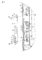
以下に、図9および図10を参照して、テレビ10の製造方法の一部について例示する。なお、テレビ10の製造方法は、以下の方法に限らない。図9は、テレビ10の製造方法の一例を示すテレビ10の断面図である。図10は、ベース32およびモジュール基板48を分解して示す斜視図である。
Below, with reference to FIG. 9 and FIG. 10, a part of manufacturing method of the
まず、マスク31の溝部74の底面74aに、第2の両面テープ85を貼り付ける。次に、図9の矢印A1で示すように、レンズ部83を溝部74に嵌め込み、第2の両面テープ85によってレンズ部83を溝部74に固定する。
First, the 2nd double-
次に、図9の矢印A2で示すように、第1の両面テープ71が貼り付けられたパネル68を、マスク31の縁部62の内側に嵌め込む。パネル68は、第1の両面テープ71によって、壁部61の外面65に固定される。同時に、第1の両面テープ71によって、レンズ部83がパネル68に固定される。
Next, as shown by an arrow A <b> 2 in FIG. 9, the
次に、図9の矢印A3で示すように、第3の両面テープ92が貼り付けられた透光部材91を、壁部61の内面66に固定する。図7に示すように、透光部材91を壁部61に固定するときに、透光部材91の角部91aを凸部95に係合させる。これにより、第1の開口部73が透光部材91に塞がれる。
Next, as shown by an arrow A3 in FIG. As shown in FIG. 7, when the
次に、図10に示すように、ベース32にモジュール基板48を取り付ける。ベース32には、一対のボス(取付部、固定部、支持部)101,102と、リブ(係合部、凸部)103とが設けられている。ボス101,102およびリブ103は、それぞれベース32の底部から、マスク31に向かって突出している。リブ103は、ボス102と一体に設けられている。
Next, as shown in FIG. 10, the
モジュール基板48に、一対のネジ孔(孔、取付部、固定部)105と、スリット(溝、凹部、係合部)106とが設けられている。ネジ孔105は、ボス101,102に対応している。スリット106は、リブ103に対応している。
The
モジュール基板48はボス101,102に載置される。この際、モジュール基板48のスリット106に、リブ103が嵌り込む。さらに、モジュール基板48に実装されたスイッチ54の操作部55が、それぞれキーパッド38の突出部39に面する。
The
例えばネジのような固定具108が、ネジ孔105を通ってボス101,102にそれぞれねじ込まれる。これにより、モジュール基板48がベース32のボス101,102に固定される。なお、モジュール基板48はこれに限らず、爪を用いた固定のような他の方法によってベース32に取り付けられても良い。
For example, a
次に、図9の矢印A4で示すように、マスク31をベース32に取り付ける。マスク31は、例えば爪やネジによって、ベース32に固定される。これにより、押圧部材97が透光部材91に弾性的に当接し、透光部材91を壁部61に押圧する。テレビ10は、以上のような工程を経て製造される。
Next, the
前記構成のテレビ10によれば、LED96が発した光は、透光部材91を通過して、レンズ部83の一方の端部83aに入る。該光は、第1の開口部73と第2の開口部78との間に設けられた中間部81に配置されたレンズ部83の内側で反射し、レンズ部83の他方の端部83bから出る。すなわち、LED96が発光すると、レンズ部83の他方の端部83bが光る。レンズ部83の他方の端部83bを光らせることで、例えばテレビ10はユーザに、電源のオンまたはオフ、録画または視聴予約のオンまたはオフ、通信状態、および処理状態のような、各種状態を通知する。
According to the
第2の開口部78の周囲に水のような液体がかかった場合、該液体は第2の開口部78に入ることがある。中間部81の一部が第1および第2の両面テープ71,85によって塞がれているため、浸入した液体の少なくとも一部が中間部81で塞き止められる。中間部81を通過した液体は、透光部材91および第3の両面テープ92によって塞き止められる。透光部材91および第3の両面テープ92によって塞き止められた液体は、例えばLED96や他の電子部品が発する熱により蒸発し、第2の開口部78から筐体15の外に排出される。
When a liquid such as water splashes around the
上記のように、第1の開口部73が、筐体15の内側から壁部61に固定された透光部材91によって塞がれている。これにより、水のような液体が第1の開口部73から筐体15の内部に浸入することを抑制できる。すなわち、レンズ部83が筐体15の外部に露出するようなデザインのテレビ10であっても液体の浸入を抑制できる。したがってレンズ部83を筐体15の外部から水密に覆う必要がなくなり、防水構造であるテレビ10の設計自由度が向上する。
As described above, the
一方の端部83aが第1の開口部73に収容されたレンズ部83は、防水性を有する第1および第2の両面テープ71,85によって、筐体15に固定される。これにより、レンズ部83が固定された部分が防水され、テレビ10の防水性が向上する。さらに、第1および第2の両面テープ71,85によってレンズ部83を固定することで、レンズ部83の振動を抑制できる。
The
第1および第2の両面テープ71,85が、中間部81とレンズ部83との間の隙間の少なくとも一部を塞ぐ。これにより、中間部81とレンズ部83との間の隙間から筐体15の内部に水のような液体が浸入することを抑制できる。
The first and second double-
透光部材91は、防水性を有する第3の両面テープ92によって壁部61に固定されている。これにより、透光部材91が壁部61に固定された部分が防水され、テレビ10の防水性が向上する。
The
第2の開口部78の少なくとも一部が、第1の開口部73からずれた位置に設けられている。これにより、第2の開口部78から第1の開口部73までの間で、水のような液体が留まりやすくなる。したがって、水のような液体が筐体15の内部に浸入することを抑制できる。
At least a part of the
第2の開口部78は、縁部62に設けられた切欠き部76と、パネル68とによって形成される。これにより、レンズ部83が取り付けやすくなり、テレビ10を容易に製造することができる。
The
筐体15に、第1の開口部73と第2の開口部78との間をつなぐ中間部81が設けられている。第1および第2の両面テープ71,85は、中間部81の少なくとも一部を塞ぐ。これにより、中間部81とレンズ部83との間の隙間から筐体15の内部に水のような液体が浸入することを抑制できる。
The
中間部81は、溝部74が設けられたマスク31と、溝部74を覆うパネル68とによって形成される。第1の両面テープ71は、マスク31にパネル68を固定するとともに、パネル68にレンズ部83を固定する。これにより、テレビ10の材料費の増加を抑制するとともに、製造工程の増加を抑制できる。
The
LED96を収容する収容部98が設けられた押圧部材97は、透光部材91を壁部61に押圧している。これにより、透光部材91が壁部61から剥離することを抑制するとともに、透光部材91と壁部61との間から水のような液体が筐体15の内部に侵入することを抑制できる。さらに、押圧部材97はLED96の光漏れも抑制するため、テレビ10の材料費の増加を抑制できる。
The pressing
溝部74に、段部77が設けられている。これにより、段部77で水のような液体が留まりやすくなる。したがって、水のような液体が筐体15の内部に浸入することを抑制できる。
A stepped
収容部98の周りにおいて、押圧部材97のモジュール基板48の中央に近い部分は、押圧部材97のモジュール基板48の中央から遠い部分よりも薄く形成される。これにより、モジュール基板48の電子部品が実装可能な領域を広く形成することができる。
A portion of the pressing
LED96が発光することでレンズ部83の他方の端部83bが光る。このように、筐体15の内部に水のような液体が浸入することを防止した上で、筐体15の外部に露出したレンズ部83の他方の端部83bを光らせることができる。
When the
なお、テレビ10はLED96の代わりに、例えば照度センサおよびCMOSセンサのような光学センサを有しても良い。該光学センサを有するテレビ10は、筐体15の内部に水のような液体が浸入することを防止した上で、例えば筐体15の外部の明るさを検知したり、筐体15の外部の映像を撮影したりできる。
Note that the
次に、図11ないし図14を参照して、第2の実施の形態について説明する。なお、以下に開示する実施形態において、第1の実施形態のテレビ10と同一の機能を有する構成部分には同一の参照符号を付す。さらに、当該構成部分については、その説明を一部または全て省略することがある。
Next, a second embodiment will be described with reference to FIGS. Note that, in the embodiments disclosed below, the same reference numerals are assigned to components having the same functions as those of the
図11は、第2の実施の形態に係るスレートコンピュータ(パーソナルコンピュータ、タブレットPC、電子機器)131を示す斜視図である。図12は、スレートコンピュータの一部を拡大して示す斜視図である。スレートコンピュータ131は、防水構造の一例である。 FIG. 11 is a perspective view showing a slate computer (personal computer, tablet PC, electronic device) 131 according to the second embodiment. FIG. 12 is an enlarged perspective view showing a part of the slate computer. The slate computer 131 is an example of a waterproof structure.
図11に示すように、スレートコンピュータ131は、筐体15を備えている。筐体15は、筐体15の前面21を形成するマスク31と、ベース32とを有している。ベース32は、筐体15の側面を形成する側壁34を有している。
As shown in FIG. 11, the slate computer 131 includes a
筐体15の前面21に、カメラ部(部分、領域)133が設けられている。カメラ部133には、カメラ開口134と、フラッシュ開口135と、センサ開口136とがそれぞれ設けられている。
A camera unit (part, region) 133 is provided on the
図13は、スレートコンピュータ131を分解して示す斜視図である。図13に示すように、カメラ部133は、パネル68に設けられている。パネル68は、例えばガラスパネルに静電気式のタッチパネルを取り付けることで形成される。
FIG. 13 is an exploded perspective view showing the slate computer 131. As shown in FIG. 13, the camera unit 133 is provided on the
カメラ開口134は、筐体15の内部に収容されたカメラユニット138の少なくとも一部を露出させる。カメラユニット138は、CMOSセンサのような光学センサおよびレンズを有している。フラッシュ開口135は、例えばレンズ139を露出させる。レンズ139は、筐体15の内部に収容されたLEDのような発光素子によって光らせられる。センサ開口136は、例えば他のレンズ140を露出させる。レンズ140は、筐体15の内部に収容された照度センサのような光学センサに、筐体15の外部の光を導く。
The camera opening 134 exposes at least a part of the camera unit 138 accommodated in the
図12に示すように、側壁34から、例えば電源ボタンであるボタン部材36が突出している。第1の実施形態と同様に、ボタン部材36は側壁34に設けられたボタン開口35に挿通されており、該ボタン開口35はキーパッド38に塞がれている。キーパッド38は、固定部材41の保持部43によって、側壁34に押圧されている。
As shown in FIG. 12, a
パネル68と、縁部62に設けられた切欠き部76とによって、三つの第2の開口部78が形成されている。第2の開口部78から、レンズ部83の他方の端部83bがそれぞれ露出されている。パネル68に、第2の開口部78から露出されたレンズ部83にそれぞれ対応する複数の図形が表示されている。
Three
図14は、分解されたスレートコンピュータ131の一部を拡大して示す斜視図である。図14に示すように、パネル68に面するレンズ部83の一部は、壁部61の外面65と略同一平面を形成する。
FIG. 14 is an enlarged perspective view showing a part of the disassembled slate computer 131. As shown in FIG. 14, a part of the
前記構成のスレートコンピュータ131によれば、第1の実施形態と同様に、第1の開口部73が、筐体15の内側から壁部61に固定された透光部材91によって塞がれている。これにより、水のような液体が第1の開口部73から筐体15の内部に浸入することを抑制できる。すなわち、レンズ部83が筐体15の外部に露出するようなデザインのスレートコンピュータ131であっても液体の浸入を抑制でき、防水構造であるスレートコンピュータ131の設計自由度が向上する。
According to the slate computer 131 having the above-described configuration, the
上記のように、防水構造はテレビ10やスレートコンピュータ131に限らず、例えば、ポータブルコンピュータ、PDA(携帯情報端末)、携帯電話、およびスマートフォンのような他の種類の電子機器であっても良い。
As described above, the waterproof structure is not limited to the
次に、図15を参照して、第3の実施の形態について説明する。図15は、第3の実施形態のスレートコンピュータ131の一部を示す断面図である。第3の実施形態において、センサ開口136は第2の開口部の一例であり、レンズ140はレンズ部の一例である。 Next, a third embodiment will be described with reference to FIG. FIG. 15 is a cross-sectional view illustrating a part of the slate computer 131 according to the third embodiment. In the third embodiment, the sensor opening 136 is an example of a second opening, and the lens 140 is an example of a lens part.
モジュール基板48の第1の面51に、照度センサ145が実装されている。照度センサ145は、電子部品および光学センサの一例である。照度センサ145は、第1の開口部73に面している。
An illuminance sensor 145 is mounted on the
レンズ140は、第1の開口部73とセンサ開口136との間に設けられた中間部81に配置される。レンズ140の一方の端部140aは第1の開口部73に収容され、他方の端部140bはセンサ開口136から筐体15の外部に露出される。
The lens 140 is disposed in an
前記構成のスレートコンピュータ131によれば、第1の実施形態と同様に、第1の開口部73が、筐体15の内側から壁部61に固定された透光部材91によって塞がれている。これにより、レンズ140が筐体15の外部に露出するようなデザインのスレートコンピュータ131であっても液体の浸入を抑制でき、防水構造であるスレートコンピュータ131の設計自由度が向上する。
According to the slate computer 131 having the above-described configuration, the
上記のように、第2の開口部は、LED96によって光るレンズ部83が露出する第2の開口部78、照度センサ111に光を導くレンズ140が露出するセンサ開口136、および他の開口部であっても良い。第2の開口部は、例えば、カメラユニット138を露出させるカメラ開口134、および発光素子によって光るレンズ139が露出するフラッシュ開口135のような他の開口部であっても良い。
As described above, the second opening is the
本明細書において述べた「防水」は、液体の浸入を完全に遮断することに限らない。「防水」は、例えば、液体の浸入を抑制すること、パッキング、液体を塞き止めること、堰、隙間を塞ぐこと、および水の進行を一部(一時)でも阻止できること、のような意味を包含する。さらに言えば、「防水」には単なる「流路内の括れ」も含まれる。 The “waterproofing” described in the present specification is not limited to completely blocking the ingress of liquid. “Waterproof” means, for example, suppressing liquid intrusion, packing, blocking liquid, weirs, closing gaps, and partially (temporarily) blocking the progress of water. Include. Furthermore, “waterproofing” includes simple “constriction in the flow path”.
本発明のいくつかの実施形態を説明したが、これらの実施形態は、例として提示したものであり、発明の範囲を限定することは意図していない。これら新規な実施形態は、その他の様々な形態で実施されることが可能であり、発明の要旨を逸脱しない範囲で、種々の省略、置き換え、変更を行うことができる。これら実施形態やその変形は、発明の範囲や要旨に含まれるとともに、特許請求の範囲に記載された発明とその均等の範囲に含まれる。 Although several embodiments of the present invention have been described, these embodiments are presented by way of example and are not intended to limit the scope of the invention. These novel embodiments can be implemented in various other forms, and various omissions, replacements, and changes can be made without departing from the scope of the invention. These embodiments and modifications thereof are included in the scope and gist of the invention, and are included in the invention described in the claims and the equivalents thereof.
例えば、上記実施形態において、マスク31およびパネル68が、それぞれ第1の部材および第2の部材の一例であったが、本発明はこれに限らない。例えば、ベース32が第1の部材の一例で、マスク31が第2の部材の一例であっても良い。
For example, in the above embodiment, the
さらに、第1および第2の両面テープ71,85が中間部81を完全に塞いでも良い。また、第1の開口部73と第2の開口部78とが重なっていても良い。電子部品はLED96のような発光する部品や照度センサ111のような光学センサに限らず、コネクタやスピーカーのような他の部品であっても良い。
Further, the first and second double-
10…テレビ、15…筐体、31…マスク、48…モジュール基板、61…壁部、68…パネル、71…第1の両面テープ、73…第1の開口部、78…第2の開口部、81…中間部、83…レンズ部、83a…一方の端部、83b…他方の端部、85…第2の両面テープ、91…透光部材、92…第3の両面テープ、96…LED、97…押圧部材、98…収容部、131…スレートコンピュータ、136…センサ開口、140…レンズ、145…照度センサ。
DESCRIPTION OF
一つの実施の形態に係る防水構造は、筐体と、基板と、レンズ部と、透光部材とを備える。前記筐体は、第1の開口部が設けられた壁部を有する第1の部材と、前記第1の部材に取り付けられて前記壁部の外部から前記第1の開口部を覆った第2の部材と、を有し、前記第1の開口部に通じるとともに前記筐体の外部に開口した第2の開口部が、少なくとも一部が前記第1の開口部からずれた位置で設けられる。前記基板は、前記筐体に収容され、前記第1の開口部に面した電子部品が実装される。前記レンズ部は、少なくとも一部が前記第1の開口部に収容され、前記第2の開口部から前記筐体の外部に露出される。前記透光部材は、前記筐体の内側から前記壁部に固定され、前記第1の開口部を塞ぐ。 A waterproof structure according to one embodiment includes a housing, a substrate, a lens unit, and a translucent member. The housing includes a first member having a wall portion provided with a first opening, and a second member attached to the first member and covering the first opening from the outside of the wall portion. A second opening that communicates with the first opening and opens to the outside of the housing is provided at a position that is at least partially offset from the first opening . The board is accommodated in the housing, and an electronic component facing the first opening is mounted thereon. At least a part of the lens portion is accommodated in the first opening, and is exposed to the outside of the housing from the second opening . The translucent member is fixed to the wall portion from the inside of the housing and closes the first opening.
さらに、第1および第2の両面テープ71,85が中間部81を完全に塞いでも良い。
また、第1の開口部73と第2の開口部78とが重なっていても良い。電子部品はLED
96のような発光する部品や照度センサ111のような光学センサに限らず、コネクタや
スピーカーのような他の部品であっても良い。
以下に、本願の出願当初の特許請求の範囲の内容を付記する。
[1]第1の開口部が設けられた壁部を有した第1の部材と、前記第1の部材に取り付けられて前記第1の開口部を覆った第2の部材と、を有し、前記第1の開口部に通じて外部に開口した第2の開口部が設けられた筐体と、
前記筐体に収容され、前記第1の開口部に面した電子部品が実装された基板と、
一方の端部が前記第1の開口部に収容され、他方の端部が前記第2の開口部から前記筐体の外部に露出されたレンズ部と、
前記レンズ部を前記筐体に固定するとともに、前記第1の開口部と前記第2の開口部との間に設けられて前記レンズ部の一部が配置された中間部の少なくとも一部を塞いだ防水性を有する第1の接着部と、
前記筐体の内側から前記第1の開口部を塞いだ透光部材と、
前記透光部材を前記壁部に固定した防水性を有する第2の接着部と、
を具備した防水構造。
[2]開口部が設けられた壁部を有した筐体と、
前記筐体に収容され、前記開口部に面した電子部品が実装された基板と、
少なくとも一部が前記開口部に収容され、前記筐体の外部に露出されたレンズ部と、
前記筐体の内側から前記壁部に固定され、前記開口部を塞いだ透光部材と、
を具備した防水構造。
[3]前記レンズ部を前記筐体に固定した防水性を有する第1の接着部をさらに具備した[2]の防水構造。
[4]前記第1の接着部が、前記開口部から前記筐体の外部までの間の少なくとも一部を塞いだ[3]に記載の防水構造。
[5]前記透光部材を前記壁部に固定した防水性を有する第2の接着部をさらに具備した[2]または[4]に記載の防水構造。
[6]前記開口部に通じるとともに前記筐体の外部に開口した他の開口部が、少なくとも一部が前記開口部からずれた位置で前記筐体に設けられ、
前記レンズ部が前記他の開口部から前記筐体の外部に露出された[2]または[5]に記載の防水構造。
[7]前記筐体が、前記壁部が設けられた第1の部材と、前記第1の部材に取り付けられて前記開口部を覆った第2の部材と、を有し、
前記他の開口部が、前記第1の部材と前記第2の部材とによって形成された[2]または[6]に記載の防水構造。
[8]前記筐体に、前記開口部と前記他の開口部との間をつなぐ中間部が設けられ、
前記レンズ部の一部が前記中間部に配置され、
前記第1の接着部が、前記中間部の少なくとも一部を塞いだ[7]に記載の防水構造。
[9]前記中間部が、前記筐体の前記第1の部材と前記第2の部材とによって形成され、
前記第1の接着部の一部が前記第1の部材を前記第2の部材に固定した[8]に記載の防水構造。
[10]前記基板に取り付けられ、前記電子部品が収容されるとともに前記開口部に向いて開口した収容部が設けられ、前記透光部材を前記壁部に押圧する押圧部材をさらに具備した[2]または[9]に記載の防水構造。
[11]前記電子部品が発光する[2]または[10]に記載の防水構造。
[12]前記電子部品が光学センサである[2]または[10]に記載の防水構造。
Further, the first and second double-
Further, the
It is not limited to a light emitting component such as 96 or an optical sensor such as the illuminance sensor 111, but may be another component such as a connector or a speaker.
The contents of the claims at the beginning of the filing of the present application will be added below.
[1] having a first member having a wall portion provided with a first opening, and a second member attached to the first member and covering the first opening. A housing provided with a second opening that opens to the outside through the first opening;
A substrate mounted in the housing and mounted with an electronic component facing the first opening;
One end is accommodated in the first opening, and the other end is exposed to the outside of the housing from the second opening, and
The lens unit is fixed to the housing, and at least a part of an intermediate part provided between the first opening and the second opening and where a part of the lens unit is disposed is blocked. A first adhesive portion having waterproof properties;
A translucent member blocking the first opening from the inside of the housing;
A second adhesive portion having a waterproof property in which the translucent member is fixed to the wall portion;
Waterproof structure.
[2] a housing having a wall provided with an opening;
A board that is housed in the housing and on which electronic components facing the opening are mounted;
At least a portion of the lens housed in the opening and exposed to the outside of the housing;
A translucent member fixed to the wall from the inside of the housing and closing the opening;
Waterproof structure.
[3] The waterproof structure according to [2], further including a waterproof first adhesive portion that fixes the lens portion to the housing.
[4] The waterproof structure according to [3], wherein the first adhesive portion blocks at least a part between the opening and the outside of the housing.
[5] The waterproof structure according to [2] or [4], further including a waterproof second adhesive portion in which the translucent member is fixed to the wall portion.
[6] Another opening that communicates with the opening and opens to the outside of the housing is provided in the housing at a position where at least part of the opening is displaced from the opening,
The waterproof structure according to [2] or [5], wherein the lens portion is exposed to the outside of the housing from the other opening.
[7] The housing includes a first member provided with the wall portion, and a second member attached to the first member and covering the opening,
The waterproof structure according to [2] or [6], wherein the other opening is formed by the first member and the second member.
[8] The housing is provided with an intermediate portion that connects between the opening and the other opening,
A part of the lens part is disposed in the intermediate part,
The waterproof structure according to [7], wherein the first adhesive portion covers at least a part of the intermediate portion.
[9] The intermediate portion is formed by the first member and the second member of the housing,
The waterproof structure according to [8], wherein a part of the first adhesive portion fixes the first member to the second member.
[10] The apparatus further includes a pressing member that is attached to the substrate, accommodates the electronic component and opens toward the opening, and presses the translucent member against the wall [2] ] Or the waterproof structure according to [9].
[11] The waterproof structure according to [2] or [10], wherein the electronic component emits light.
[12] The waterproof structure according to [2] or [10], wherein the electronic component is an optical sensor.
Claims (12)
前記筐体に収容され、前記第1の開口部に面した電子部品が実装された基板と、
一方の端部が前記第1の開口部に収容され、他方の端部が前記第2の開口部から前記筐体の外部に露出されたレンズ部と、
前記レンズ部を前記筐体に固定するとともに、前記第1の開口部と前記第2の開口部との間に設けられて前記レンズ部の一部が配置された中間部の少なくとも一部を塞いだ防水性を有する第1の接着部と、
前記筐体の内側から前記第1の開口部を塞いだ透光部材と、
前記透光部材を前記壁部に固定した防水性を有する第2の接着部と、
を具備した防水構造。 A first member having a wall portion provided with a first opening; and a second member attached to the first member and covering the first opening. A housing provided with a second opening that opens to the outside through one opening;
A substrate mounted in the housing and mounted with an electronic component facing the first opening;
One end is accommodated in the first opening, and the other end is exposed to the outside of the housing from the second opening, and
The lens unit is fixed to the housing, and at least a part of an intermediate part provided between the first opening and the second opening and where a part of the lens unit is disposed is blocked. A first adhesive portion having waterproof properties;
A translucent member blocking the first opening from the inside of the housing;
A second adhesive portion having a waterproof property in which the translucent member is fixed to the wall portion;
Waterproof structure.
前記筐体に収容され、前記開口部に面した電子部品が実装された基板と、
少なくとも一部が前記開口部に収容され、前記筐体の外部に露出されたレンズ部と、
前記筐体の内側から前記壁部に固定され、前記開口部を塞いだ透光部材と、
を具備した防水構造。 A housing having a wall provided with an opening;
A board that is housed in the housing and on which electronic components facing the opening are mounted;
At least a portion of the lens housed in the opening and exposed to the outside of the housing;
A translucent member fixed to the wall from the inside of the housing and closing the opening;
Waterproof structure.
前記レンズ部が前記他の開口部から前記筐体の外部に露出された請求項2または5に記載の防水構造。 Another opening that communicates with the opening and opens to the outside of the housing is provided in the housing at a position that is at least partially offset from the opening,
The waterproof structure according to claim 2 or 5, wherein the lens portion is exposed to the outside of the housing from the other opening.
前記他の開口部が、前記第1の部材と前記第2の部材とによって形成された請求項2または6に記載の防水構造。 The housing includes a first member provided with the wall portion, and a second member attached to the first member and covering the opening,
The waterproof structure according to claim 2 or 6, wherein the other opening is formed by the first member and the second member.
前記レンズ部の一部が前記中間部に配置され、
前記第1の接着部が、前記中間部の少なくとも一部を塞いだ請求項7に記載の防水構造。 The casing is provided with an intermediate portion that connects between the opening and the other opening,
A part of the lens part is disposed in the intermediate part,
The waterproof structure according to claim 7, wherein the first adhesive portion covers at least a part of the intermediate portion.
前記第1の接着部の一部が前記第1の部材を前記第2の部材に固定した請求項8に記載の防水構造。 The intermediate portion is formed by the first member and the second member of the housing,
The waterproof structure according to claim 8, wherein a part of the first adhesive portion fixes the first member to the second member.
Priority Applications (2)
| Application Number | Priority Date | Filing Date | Title |
|---|---|---|---|
| JP2012052913A JP2013187456A (en) | 2012-03-09 | 2012-03-09 | Waterproof structure |
| US13/735,206 US20130235539A1 (en) | 2012-03-09 | 2013-01-07 | Waterproof structure |
Applications Claiming Priority (1)
| Application Number | Priority Date | Filing Date | Title |
|---|---|---|---|
| JP2012052913A JP2013187456A (en) | 2012-03-09 | 2012-03-09 | Waterproof structure |
Publications (1)
| Publication Number | Publication Date |
|---|---|
| JP2013187456A true JP2013187456A (en) | 2013-09-19 |
Family
ID=49113953
Family Applications (1)
| Application Number | Title | Priority Date | Filing Date |
|---|---|---|---|
| JP2012052913A Pending JP2013187456A (en) | 2012-03-09 | 2012-03-09 | Waterproof structure |
Country Status (2)
| Country | Link |
|---|---|
| US (1) | US20130235539A1 (en) |
| JP (1) | JP2013187456A (en) |
Cited By (1)
| Publication number | Priority date | Publication date | Assignee | Title |
|---|---|---|---|---|
| KR20170098122A (en) * | 2016-02-19 | 2017-08-29 | 삼성전자주식회사 | Eletronic device |
Families Citing this family (4)
| Publication number | Priority date | Publication date | Assignee | Title |
|---|---|---|---|---|
| JP5973335B2 (en) | 2012-12-13 | 2016-08-23 | 京セラ株式会社 | Electronic device having waterproof structure |
| TWM466306U (en) * | 2013-06-28 | 2013-11-21 | Wistron Corp | Optical touch panel system and optical touch panel device thereof |
| JP5901725B1 (en) * | 2014-10-17 | 2016-04-13 | 三菱電機株式会社 | Waterproof control unit and its assembly method |
| CN105116967B (en) * | 2015-08-31 | 2017-09-26 | 广东欧珀移动通信有限公司 | Terminal front cover component and terminal |
Citations (8)
| Publication number | Priority date | Publication date | Assignee | Title |
|---|---|---|---|---|
| JPS63122848U (en) * | 1987-02-04 | 1988-08-10 | ||
| JPH03101597A (en) * | 1989-09-14 | 1991-04-26 | Matsushita Electric Works Ltd | Wireless receiver |
| JPH0864978A (en) * | 1994-08-18 | 1996-03-08 | Fujitsu Ltd | Electronic device housing structure |
| JPH08288665A (en) * | 1995-04-18 | 1996-11-01 | Casio Comput Co Ltd | Case structure |
| JP2006284683A (en) * | 2005-03-31 | 2006-10-19 | Casio Hitachi Mobile Communications Co Ltd | Mobile type electronic apparatus having external illuminating function and light guide member |
| JP2012095144A (en) * | 2010-10-27 | 2012-05-17 | Kyocera Corp | Electronic equipment |
| JP2012134443A (en) * | 2010-11-30 | 2012-07-12 | Panasonic Corp | Electronic apparatus |
| JP2012209467A (en) * | 2011-03-30 | 2012-10-25 | Komatsu Ltd | Power storage device and construction machinery including the same |
-
2012
- 2012-03-09 JP JP2012052913A patent/JP2013187456A/en active Pending
-
2013
- 2013-01-07 US US13/735,206 patent/US20130235539A1/en not_active Abandoned
Patent Citations (8)
| Publication number | Priority date | Publication date | Assignee | Title |
|---|---|---|---|---|
| JPS63122848U (en) * | 1987-02-04 | 1988-08-10 | ||
| JPH03101597A (en) * | 1989-09-14 | 1991-04-26 | Matsushita Electric Works Ltd | Wireless receiver |
| JPH0864978A (en) * | 1994-08-18 | 1996-03-08 | Fujitsu Ltd | Electronic device housing structure |
| JPH08288665A (en) * | 1995-04-18 | 1996-11-01 | Casio Comput Co Ltd | Case structure |
| JP2006284683A (en) * | 2005-03-31 | 2006-10-19 | Casio Hitachi Mobile Communications Co Ltd | Mobile type electronic apparatus having external illuminating function and light guide member |
| JP2012095144A (en) * | 2010-10-27 | 2012-05-17 | Kyocera Corp | Electronic equipment |
| JP2012134443A (en) * | 2010-11-30 | 2012-07-12 | Panasonic Corp | Electronic apparatus |
| JP2012209467A (en) * | 2011-03-30 | 2012-10-25 | Komatsu Ltd | Power storage device and construction machinery including the same |
Cited By (2)
| Publication number | Priority date | Publication date | Assignee | Title |
|---|---|---|---|---|
| KR20170098122A (en) * | 2016-02-19 | 2017-08-29 | 삼성전자주식회사 | Eletronic device |
| KR102460423B1 (en) * | 2016-02-19 | 2022-10-31 | 삼성전자주식회사 | Eletronic device |
Also Published As
| Publication number | Publication date |
|---|---|
| US20130235539A1 (en) | 2013-09-12 |
Similar Documents
| Publication | Publication Date | Title |
|---|---|---|
| JP5100214B2 (en) | Portable terminal | |
| US8264825B2 (en) | Flat type image display apparatus | |
| US9622391B2 (en) | Mobile terminal | |
| EP2720443B1 (en) | Mobile terminal with light diffuser for a key | |
| US9462165B2 (en) | Electronic device including camera module | |
| US7950859B2 (en) | Lens cover and portable electronic device using the same | |
| US20110050986A1 (en) | Window for portable electronic device | |
| JP2013187129A (en) | Electronic apparatus | |
| CN109274787B (en) | electronic device | |
| US20130221812A1 (en) | Television | |
| JP2013187456A (en) | Waterproof structure | |
| KR20140134163A (en) | Window for display device and mobile terminal having the same | |
| US20130026340A1 (en) | Electronic device employing a button pad | |
| US20130222706A1 (en) | Television | |
| JP2022176555A (en) | Electronics | |
| US20130329928A1 (en) | Television receiver and electronic apparatus | |
| JP2009145760A (en) | Electronic device display | |
| US9348440B2 (en) | Touch screen device for a portable terminal | |
| KR20150044506A (en) | Camera Lens Module Having a Sensor | |
| CN102469724B (en) | Electronic installation | |
| US20110279747A1 (en) | Display panel unit and electronic device | |
| JP2009159531A (en) | Electronics | |
| KR101336710B1 (en) | Mobile terminal | |
| KR20150046824A (en) | Camera Lens Module Having a Sensor | |
| US11419183B2 (en) | Outer frame, terminal housing and terminal |
Legal Events
| Date | Code | Title | Description |
|---|---|---|---|
| A521 | Request for written amendment filed |
Free format text: JAPANESE INTERMEDIATE CODE: A523 Effective date: 20130614 |
|
| RD02 | Notification of acceptance of power of attorney |
Free format text: JAPANESE INTERMEDIATE CODE: A7422 Effective date: 20130730 |
|
| A02 | Decision of refusal |
Free format text: JAPANESE INTERMEDIATE CODE: A02 Effective date: 20130827 |
|
| RD07 | Notification of extinguishment of power of attorney |
Free format text: JAPANESE INTERMEDIATE CODE: A7427 Effective date: 20140319 |