JP2013173080A - Water purifying cartridge and water purifier - Google Patents
Water purifying cartridge and water purifier Download PDFInfo
- Publication number
- JP2013173080A JP2013173080A JP2012037440A JP2012037440A JP2013173080A JP 2013173080 A JP2013173080 A JP 2013173080A JP 2012037440 A JP2012037440 A JP 2012037440A JP 2012037440 A JP2012037440 A JP 2012037440A JP 2013173080 A JP2013173080 A JP 2013173080A
- Authority
- JP
- Japan
- Prior art keywords
- lid
- main body
- water
- water purification
- purified water
- Prior art date
- Legal status (The legal status is an assumption and is not a legal conclusion. Google has not performed a legal analysis and makes no representation as to the accuracy of the status listed.)
- Pending
Links
- XLYOFNOQVPJJNP-UHFFFAOYSA-N water Substances O XLYOFNOQVPJJNP-UHFFFAOYSA-N 0.000 title claims abstract description 156
- 238000001914 filtration Methods 0.000 claims abstract description 3
- 238000000746 purification Methods 0.000 claims description 44
- 230000002093 peripheral effect Effects 0.000 claims description 43
- 239000008213 purified water Substances 0.000 abstract description 49
- 210000000078 claw Anatomy 0.000 description 26
- 239000012510 hollow fiber Substances 0.000 description 11
- 239000012528 membrane Substances 0.000 description 10
- 239000003463 adsorbent Substances 0.000 description 7
- 238000003825 pressing Methods 0.000 description 7
- 230000006835 compression Effects 0.000 description 6
- 238000007906 compression Methods 0.000 description 6
- 150000002500 ions Chemical class 0.000 description 6
- 238000004140 cleaning Methods 0.000 description 4
- 238000007789 sealing Methods 0.000 description 4
- 239000008399 tap water Substances 0.000 description 4
- 235000020679 tap water Nutrition 0.000 description 4
- 238000012856 packing Methods 0.000 description 3
- OKTJSMMVPCPJKN-UHFFFAOYSA-N Carbon Chemical compound [C] OKTJSMMVPCPJKN-UHFFFAOYSA-N 0.000 description 2
- 238000007599 discharging Methods 0.000 description 2
- 239000012535 impurity Substances 0.000 description 2
- 238000012423 maintenance Methods 0.000 description 2
- 229920000122 acrylonitrile butadiene styrene Polymers 0.000 description 1
- 238000005452 bending Methods 0.000 description 1
- 239000003599 detergent Substances 0.000 description 1
- 230000003670 easy-to-clean Effects 0.000 description 1
- 229910001385 heavy metal Inorganic materials 0.000 description 1
- 239000000463 material Substances 0.000 description 1
- 238000000034 method Methods 0.000 description 1
- 239000008239 natural water Substances 0.000 description 1
- 230000000414 obstructive effect Effects 0.000 description 1
- 239000011347 resin Substances 0.000 description 1
- 229920005989 resin Polymers 0.000 description 1
- 238000001179 sorption measurement Methods 0.000 description 1
- 239000000126 substance Substances 0.000 description 1
- 239000012780 transparent material Substances 0.000 description 1
- 238000011144 upstream manufacturing Methods 0.000 description 1
- 238000003466 welding Methods 0.000 description 1
Images


Landscapes
- Separation Using Semi-Permeable Membranes (AREA)
- Treatment Of Water By Ion Exchange (AREA)
- Water Treatment By Sorption (AREA)
Abstract
Description
本発明は主に家庭で使用される水道水をろ過する浄水カートリッジ及びこれを備えた浄水器に関する。 The present invention relates to a water purification cartridge for mainly filtering tap water used at home and a water purifier provided with the same.
主に家庭で使用される浄水器として水道水の蛇口に取り付けられるタイプのものが多く用いられている。このタイプの浄水器としては例えば図8に示された浄水器81が挙げられる(特許文献1等)。
As a water purifier mainly used at home, a type of water purifier attached to tap water is often used. An example of this type of water purifier is the
浄水器81は本体部82と浄水カートリッジ83とを備える。本体部82は蛇口から供された原水(水道水)の流路の切り替えが可能な切替えレバー84を備える。そして、この切替えレバー84の操作により、原水をそのままシャワー水として吐出するか、そのままストレート水として吐出するか、浄水カートリッジ83に供給するかのいずれかを選択できるようになっている。浄水カートリッジ83は筒体を成しその内部に吸着材85,中空糸膜86を備えている。そして、この浄水カートリッジ83の浄水吐出側端部87には吸着材85,中空糸膜86によってろ過された水道水を排出するための浄水吐出孔88が複数形成されている。
The
浄水吐出孔88は、浄水カートリッジ83の下面にて露出して配置されているので、浄水器81が長期的に使用されると、シンク側からの洗浄水や洗剤の跳ね返りにより、汚れ成分やバイオフィルムが付着して閉塞気味となり、浄水の流量低下や不衛生を招く可能性がある。
Since the purified water discharge hole 88 is exposed and arranged on the lower surface of the purified
しかしながら、浄水吐出側端部87は浄水カートリッジ83の本体容器89に一体的に設けられているので、浄水吐出孔88に詰まった夾雑物を浄水カートリッジ83の外部から取り除くことは困難となっている。特に、浄水をシャワー状に吐出するために細孔の浄水吐出孔88が複数形成されている場合には、この浄水吐出孔88に詰まった夾雑物の除去はなおさら難しい。
However, since the purified water discharge
本発明は上記の事情に鑑みなされたもので浄水カートリッジの浄水吐出孔の掃除を容易にすることを技術課題とする。 This invention is made | formed in view of said situation, and makes it easy to clean the purified water discharge hole of a purified water cartridge.
そこで、本発明の浄水カートリッジは、原水をろ過するカートリッジ本体の浄水吐出側端部に、浄水吐出孔が形成された蓋部を着脱自在に設けている。 Therefore, the water purification cartridge of the present invention is detachably provided with a lid portion in which a water purification discharge hole is formed at the end of the water purification discharge side of the cartridge body that filters raw water.
また、本発明の浄水器は、原水の流路を切り替える本体部と、この本体部に接続される前記の浄水カーリッジとを備える。 Moreover, the water purifier of this invention is equipped with the main-body part which switches the flow path of raw | natural water, and the said water purifier cartridge connected to this main-body part.
前記蓋部は例えばバヨネット構造や螺合構造で前記端部に着脱自在に設けられる。 The lid portion is detachably provided at the end portion with, for example, a bayonet structure or a screwed structure.
前記浄水カートリッジにおいて、前記蓋部を回転させる摘み部をこの蓋部の外周側に設けるとよい。この態様によれば、蓋部はその外周方向への指の押圧を受け易くなる。 In the water purification cartridge, a knob for rotating the lid may be provided on the outer peripheral side of the lid. According to this aspect, the lid portion is easily subjected to finger pressing in the outer circumferential direction.
前記カートリッジ本体に対する前記蓋部の装着開始位置を示す印を、前記カートリッジ本体と前記蓋部とのそれぞれに設けるとよい。この態様によればバヨネット構造で前記端部に前記蓋部を装着させる際の当該蓋部の位置決めが容易となる。 A mark indicating a mounting start position of the lid with respect to the cartridge body may be provided on each of the cartridge body and the lid. According to this aspect, positioning of the lid portion when the lid portion is attached to the end portion with a bayonet structure is facilitated.
特に、前記各印が対向したカートリッジ本体と蓋部の配置を、このカートリッジ本体に対する蓋部の装着開始位置とするとよい。この態様によれば前記蓋部を前記端部に装着を開始させる際のこの両者の配置関係がより明確となる。 In particular, the arrangement of the cartridge main body and the lid that face each of the marks may be the mounting start position of the lid on the cartridge main body. According to this aspect, the arrangement relationship between the two when the attachment of the lid to the end is started becomes clearer.
以上の発明によれば浄水吐出孔が形成された蓋部がカートリッジ本体の浄水吐出側端部に対して着脱自在となっているので浄水吐出孔の掃除が容易となる。 According to the above invention, since the cover part in which the water purification discharge hole was formed is detachable with respect to the water purification discharge side edge part of a cartridge main body, cleaning of the water purification discharge hole becomes easy.
以下、本発明の実施形態について、家庭のキッチンなどの水道蛇口に取り付けられる浄水器を例に図面を参照しながら説明する。 Hereinafter, an embodiment of the present invention will be described with reference to the drawings, taking a water purifier attached to a water tap such as a home kitchen as an example.
[浄水器の構成]
図1に示した浄水器1は、原水の流路を切り替える本体部2と、この本体部2に接続される浄水カーリッジ3とを備える。浄水カートリッジ3はパッキン4を介して本体部2とバヨネット方式により水密的に連結される。
[Configuration of water purifier]
A water purifier 1 shown in FIG. 1 includes a
本体部2は従来の浄水器(例えば特許文献1)の本体部と基本的に同仕様となっている。すなわち、本体部2は、切替えレバー5を操作することにより、蛇口から供された原水をそのままシャワー水として吐出するか、そのままストレート水として吐出するか、浄水カートリッジ3に供給するかを選択できるようになっている。
The
浄水カートリッジ3は、活性炭等の吸着材6と複数の中空糸膜7からなる中空糸膜束とを収納する筒状の本体容器8(カートリッジ本体)を備える。この本体容器8の浄水吐出側端部9に近い外周面には本体部2から原水を受け入れるための原水受入口10(流入口)が設けられている。そして、本体容器8の浄水吐出側端部9の開口部11には浄水を吐出するための浄水吐出孔120が複数形成された蓋部12が取り外し可能に装着されている。浄水吐出孔120は、浄水カートリッジ3(の蓋部12)の下面に、外部に露出して配置されており、浄水は浄水吐出孔120から直接外部に吐出する。
The water purification cartridge 3 includes a cylindrical main body container 8 (cartridge main body) that stores an adsorbent 6 such as activated carbon and a hollow fiber membrane bundle composed of a plurality of
本体容器8の浄水吐出側端部9付近の内部には円筒状突起部13が本体容器8と同軸に形成されている。さらに、この円筒状突起部13には筒状部材14がOリング15を介して止水的に嵌装されている。また、この筒状部材14の外周面と本体容器8の内周面との空間には吸着材6が充填されている。そして、この吸着材6の保持のためにその上流側,下流側にはそれぞれリング状のフィルタ16,17が固定されている。尚、図示省略されているが、下流側のフィルタ17上の筒状部材14の外周面と本体容器8の内周面との空間には原水に含まれる特定のイオン(例えば溶解性鉛等の重金属イオン等)の除去のためにイオン交換体が適宜に充填される。
A
筒状部材14には複数の中空糸膜7を束ねて逆U字状に折り曲げた中空糸膜束が適宜複数収納されている。この中空糸膜束の両端部は筒状部材14の排水側端部18付近の内部において硬化性樹脂からなる封止部材19によって止水的に封止固定されている。そして、この封止固定された個々の中空糸膜7の両末端は、予め排水側端部18の端面と同一平面上にて封止部材19と共に当該端部18の径方向に均等に切断されており、蓋部12の浄水吐出孔120に向かって開口した状態となっている。
A plurality of hollow fiber membrane bundles obtained by bundling a plurality of
また、本体容器8の上端は前記中空糸膜束を備えた筒状部材14の装着や吸着材6の充填さらにはイオン交換体の充填を容易に確認できるように開口されている。この開口部は内蓋19が嵌装された後に超音波溶着等により密閉される。内蓋19は、本体容器8内部の状態、特に筒状部材14やイオン交換体の取付け状態、または吸着材6やイオン交換体の汚れを目視で確認できるように透明の材質(例えば透明ABS樹脂)からなる。尚、内蓋19は着脱自在に本体容器8の上端に装着される外蓋20によって保護される。
Further, the upper end of the
次いで、浄水吐出側端部9の蓋部の実施形態について説明する。蓋部の着脱構造は以下に例示されるようにバヨネット構造や螺合構造が挙げられる。特に、バヨネット構造は図示された態様に限定されず、この態様以外の周知のバヨネット構造も適用できる。
Next, an embodiment of the lid portion of the purified water discharge
[実施形態1]
図1に示した実施形態1の蓋部12はオス型のバヨネット構造を採用している。
[Embodiment 1]
The
この蓋部12は、浄水吐出孔120が形成された円板状の蓋本体121と、この蓋本体121上にて浄水吐出側端部9の開口部11に嵌装される短管部122と、この短管部122の外周面に一体形成され浄水吐出側端部9のバヨネット溝21と係合するバヨネット爪123を有し、浄水吐出孔120は蓋本体121の中央付近にて複数形成されている。
The
バヨネット爪123は短管部122の外周面にて等間隔に複数突出形成され、バヨネット爪123と係合するバヨネット溝21が浄水吐出側端部9の内周面に形成されている。尚、バヨネット溝21を短管部122側に形成し、バヨネット爪123を浄水吐出側端部9側に形成してもよい。
A plurality of
バヨネット溝21は、バヨネット爪123と係合する係止溝211と、バヨネット爪123を係止溝211内に案内する切欠部212とから成る。係止溝211は開口部11の内周面に沿って一定の長さで円弧状に形成されている。
The
そして、浄水吐出側端部9の内周面には蓋部12の短管部122との水密的な接続を図るためにOリング等のシール部材22が装着されている。シール部材22は、短管部122側(の外周面)に装着されていてもよい。図示されたシール部材22は径方向圧縮仕様となっているが、この仕様に限定することなく、例えば軸方向圧縮仕様のもの(例えば平パッキン)を採用してもよい。この軸方向圧縮仕様のシール部材は例えば蓋部12と筒状部材14との間、または蓋部12と浄水吐出側端部9との間に介在するように配置される。
A
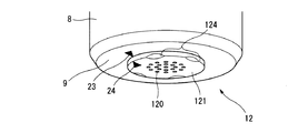
また、図2に例示したように、浄水吐出側端部9,蓋部12の外面には浄水吐出側端部9に対して蓋部12を挿し込む際の位置決めを示す印23,24をそれぞれ付するとよい。これにより、本体容器8への蓋部12の装着を開始する際の本体容器8に対する蓋部12の位置決めが容易となり、本体容器8への蓋部12の装着操作を効率的に行える。
Moreover, as illustrated in FIG. 2, marks 23 and 24 indicating the positioning when the
例えば、蓋部12のバヨネット爪123が浄水吐出側端部9の切欠部212に導入された時に図2に示したように印23,24が対向するように、印23,24を浄水吐出側端部9,蓋部12の外面にそれぞれ付するとよい。この態様によれば蓋部12を浄水吐出側端部9に装着を開始させる際のこの端部9と蓋部12との配置関係がより明確となるので、本体容器8への蓋部12の装着操作を効率的に行える。
For example, when the
尚、図2に示したように蓋本体121の周縁部は凹凸部124等の面取り加工を施してもよい。または、蓋本体121を多角形状(例えば六角形状)に形成してもよい。これらの態様によれば、蓋本体121はその周方向への押圧(例えば指の押圧)を受け易くなり、蓋部12を回転させ易くなる。
As shown in FIG. 2, the peripheral portion of the lid
次に図1,図2を参照しながら本実施形態の蓋部12の取り扱い例について説明する。
Next, an example of handling the
蓋部12を浄水カートリッジ3の本体容器8に装着させる際、先ず、図2に示したように蓋部12の印24を本体容器8の浄水吐出側端部9の印23と対向させた状態で、図1に示された蓋部12の短管部122を浄水吐出側端部9の開口部11に挿入させる。このとき短管部122のバヨネット爪123は図1に示されたように浄水吐出側端部9の切欠部212に案内される。次いで、図2に示した状態から蓋本体121を一方向に回転させると、図1に示されたバヨネット爪123は摺動して係止溝211内に位置する。このときバヨネット爪123は係止溝211に係止された状態となり、そして、さらに蓋本体121を同方向に回転させると、バヨネット爪123は係止溝211の終端面に当接し、蓋部12が本体容器8に確実に係止された状態となる。以上のように蓋部12は本体容器8に装着される。
When attaching the
この浄水カートリッジ3に原水を通水させる際には、本体部2のレバー5の操作により、原水の流路が浄水カートリッジ3側に設定される。浄水カートリッジ3内に導入された原水は、本体容器8内の吸着材6や中空糸膜7によって濾過され後、筒状部材14の排水側端部18から浄水として排出され、さらに蓋部12の浄水吐出孔120から吐出される。そして、浄水カートリッジ3のメンテナンスを行う際には、原水の給水が停止される。蓋部12を清掃する際には、蓋部12が本体容器8から取り外される。
When the raw water is passed through the water purification cartridge 3, the flow path of the raw water is set on the side of the water purification cartridge 3 by operating the
蓋部12を本体容器8から取り外す際、先ず、蓋本体121を他方向に回転させると、図1に示されたバヨネット爪123は係止溝211内を摺動しやがて切欠部212に位置する。このとき、既にバヨネット爪123は切欠部212から開放可能なため、蓋本体121を引き出すと、蓋部12は本体容器8から脱離する。このようにして蓋部12は本体容器8から取り外される。
When removing the
以上のように蓋部12は浄水カートリッジ3の本体容器8に対して着脱自在となっているので蓋部12の浄水吐出孔120の掃除が容易となる。特に、蓋部12の両面から浄水吐出孔120の洗浄、清掃を任意に行えるので、浄水吐出孔120に詰まった夾雑物を完全に除去できる。また、本体容器8の浄水吐出側端部9の内部や本体容器8内の中空糸束を備えた筒状部材14の排水側端部18も任意に洗浄、掃除できる。
As described above, since the
[実施形態2]
図3に示した実施形態2の蓋部31はメス型のバヨネット構造を採用している。
[Embodiment 2]
The
この蓋部31は、浄水吐出孔310が形成された円板状の蓋本体311と、浄水吐出側端部9の開口部11に嵌装される短管部312と、蓋本体311の周縁に設けられる周縁筒部313と、この周縁筒部313の内周面に一体形成され浄水吐出側端部9のバヨネット溝23と係合するバヨネット爪314とを有し、浄水吐出孔310は蓋本体311の中央付近にて複数形成されている。
The
バヨネット爪314は周縁筒部313の内周面にて等間隔に複数突出形成され、バヨネット爪314と係合するバヨネット溝23が浄水吐出側端部9の外周面に形成されている。尚、バヨネット溝23を周縁筒部313側に形成し、バヨネット爪314を浄水吐出側端部9側に形成してもよい。
A plurality of
バヨネット溝23は、バヨネット爪314と係合する係止溝231と、バヨネット爪314を係止溝231に案内する切欠部232とから成る。係止溝231は浄水吐出側端部9の外周面に沿って一定の長さで円弧状に形成されている。
The
そして、本実施形態においても浄水吐出側端部9の内周面には蓋部31の短管部312との水密的な接続を図るために実施形態1と同様にシール部材24が装着される。図示された径方向圧縮仕様のシール部材24に代えて軸方向圧縮仕様のシール部材(例えば平パッキン)を適用してもよい。この軸方向圧縮仕様のシール部材は実施形態1と同様に、蓋部31と筒状部材14との間、または蓋部31と浄水吐出側端部9との間に介在するように配置される。
Also in the present embodiment, the
また、図4に例示したように、本体容器8,蓋部31の外周面には本体容器8に対する蓋部31の装着開始位置を示す印32,33をそれぞれ付するとよい。本体容器8への蓋部31の装着を開始する際の本体容器8に対する蓋部31の位置決めが容易となり、本体容器8への蓋部31の装着操作を効率的に行える。
Further, as illustrated in FIG. 4, marks 32 and 33 indicating the attachment start positions of the
特に、蓋部31のバヨネット爪314が浄水吐出側端部9の切欠部232に導入された時に図4に示したように印32,33が対向するように本体容器8,蓋部31の外周面に印32,33をそれぞれ付すとよい。この態様によれば蓋部31を本体容器8に装着を開始させる際のこの本体容器8と蓋部31との配置関係がより明確となる。
In particular, when the
そして、実施形態1と同様に、蓋本体311の周縁部には凹凸部等の面取り加工を施してもよい。若しくは、蓋本体311の形状を多角形状(例えば六角形状)に形成してもよい。これにより、蓋部31はその周方向への押圧(例えば指の押圧)を受け易くなり、蓋部31を回転させ易くなる。
And like Embodiment 1, you may chamfer processes, such as an uneven | corrugated | grooved part, to the peripheral part of the lid | cover
次に図3,図4を参照しながら本実施形態の蓋部31の取り扱い例について説明する。
Next, an example of handling the
蓋部31を浄水カートリッジ3の本体容器8に装着させる際、先ず、図4に示したように蓋部31の印33を本体容器8の印32と対向させた状態で、図3に示された蓋部31の短管部312を浄水吐出側端部9の開口部11に挿入させる。このとき、周縁筒部313のバヨネット爪314は図3に示されたように浄水吐出側端部9における切欠部232に案内される。次いで、図4に示した状態から蓋部31を一方向に回転させると、図3に示されたバヨネット爪314は摺動して係止溝231内に位置する。このときバヨネット爪314は係止溝231に係止された状態となり、そして、さらに蓋部31を同方向に回転させるとバヨネット爪314は係止溝231の終端面に当接し、蓋部31は本体容器8に確実に係止された状態となる。以上のように蓋部31は本体容器8に装着される。
When attaching the
一方、浄水カートリッジ3のメンテナンス時に蓋部31を本体容器8から取り外す際には、先ず、蓋部31を他方向に回転させると、図3に示されたバヨネット爪314は、係止溝231内を摺動し、切欠部232に位置する。このとき、バヨネット爪314は切欠部232から開放可能となり、この状態から蓋部31を引き出すと、蓋部31は本体容器8から脱離する。このようにして蓋部31は本体容器8から取り外される。
On the other hand, when removing the
以上のように本実施形態の蓋部31は浄水カートリッジ3の本体容器8に対して着脱自在となっているので、実施形態1と同様に蓋部31の浄水吐出孔310の完全な掃除が容易となる。また、本体容器8の浄水吐出側端部9の内部や筒状部材14の排水側端部18も任意に洗浄や掃除ができる。さらに、蓋部31は蓋本体31の外径が本体容器8の外径と略同等となっているので蓋部31の着脱操作の際に使用者は蓋部31を持ち易くなり蓋部31を取り扱い易くなる。
As described above, since the
尚、蓋部31の他の態様としては、上述の蓋本体311の周縁部や形状の加工に代わりに、図5(a)(b)に示された蓋部41のように、周縁筒部313の外周面に摘み部42を具備させてもよい。摘み部42は、その外側面などに掛けた指により、蓋本体311の外周方向への押圧を受けて蓋部41を回転させる。摘み部42は蓋部41の周縁筒部313の外周に延設されている。摘み部42は、蓋部41の蓋本体313底面の外周側から延設されていてもよい。いずれにしても、摘み部42は、蓋部41の外周側に設けると、蓋部41を指により外周方向へ押圧し易くなる。また、図5(a)に示されたように摘み部42には指が掛けられる窪み43が形成されている。この窪み43内の周縁筒部313の外周面には上述の位置決めのための印33が付されている。
In addition, as another aspect of the
上記のように蓋部41に摘み部42が設けられることで、着脱操作時の蓋部41の操作性が向上する。特に、摘み部42が蓋部41の外周に延設されたことで、指のとの接触面積が拡大するので、摘み部42を摘んだり、押圧したりし易くなり、蓋部41の着脱操作が一層容易となる。また、摘み部42に指が掛けられる窪み43が形成されたことで、蓋部41は前記指による外周方向への押圧を容易に受けることができるので、蓋部41をより一層効率的に回転させることができる。
By providing the
[実施形態3]
図6に示した本実施形態の蓋部12a,31aは螺合構造を採用している。
[Embodiment 3]
The
すなわち、図6(a)に示された蓋部12aは実施形態1の蓋部12においてオス型螺合構造が適用された態様となっている。蓋部12aの短管部122の外周面には浄水吐出側端部9の内周面に形成された雌ねじ部91と螺合する雄ねじ部125が形成されている。
That is, the
図6(b)に示された蓋部31aは実施形態2の蓋部31においてメス型螺合構造が適用された態様となっている。蓋部31aの周縁筒部313の内周面には浄水吐出側端部9の外周面に形成された雄ねじ部92と螺合する雌ねじ部315が形成されている。
The
以上のように本実施形態の蓋部12a,31aはそれぞれ浄水カートリッジ3の本体容器8に対して着脱自在となっている。特に、本実施形態においては、螺合構造が採用されているので、本体容器8に蓋部12a,31aを装着する際の装着開始の位置決めが必要でなくなり、蓋部12a,31aの着脱操作をより一層効率的に行える。
As described above, the
尚、蓋部12a,31aの蓋本体121,311の周縁部も、凹凸部等の面取り加工を施してもよい。または、蓋本体121,311の形状を多角形状(例えば六角形状)に形成してもよい。これらの態様によれば、蓋部12a,31aはその周方向への押圧(例えば指の押圧)を受け易くなり、蓋部12a,31aの操作性が向上する。
Note that the peripheral portions of the
[実施形態4]
図7に示した本実施形態の蓋部12b,12cは蓋本体121の外径が浄水カートリッジ3の本体容器8の外径と略同等に設定されている。すなわち、図7(a)に示した蓋部12bは実施形態1の蓋部12において蓋本体121の最大外径が本体容器8の外径と略同等となっている。また、図7(b)に示した蓋部12cは実施形態3の蓋部12aおいて蓋本体121の最大外径が本体容器8の外径と略同等となっている。
[Embodiment 4]
In the
以上のように蓋部12b,12cは蓋本体121の外径が浄水カートリッジ3の本体容器8の外径と略同等となっているので、本体容器8への蓋部12b,12cの着脱操作の際に使用者は蓋部12b,12cを持ち易くなる。したがって、蓋部12b,12cの取り扱い特に着脱操作が容易となる。
As described above, the
また、蓋部12b,12cの蓋本体121の周縁部においても、凹凸部等の面取り加工を施してもよい。または、蓋本体121の形状を多角形状(例えば六角形状)に形成してもよい。これらの態様によれば、蓋部12b,12cはその周方向への押圧(例えば指の押圧)を受け易くなり、蓋部12b,12cの操作性が向上する。
In addition, chamfering processing such as uneven portions may be performed on the peripheral portion of the lid
1…浄水器
2…本体部
3…浄水カーリッジ
8…本体容器(カートリッジ本体)
9…浄水吐出側端部
12,31,12a,31a,12b,12c,41…蓋部
120,310…浄水吐出孔
42…摘み部
23,24,32,33…印
DESCRIPTION OF SYMBOLS 1 ...
9 ... Purified water discharge
Claims (7)
を特徴とする浄水カートリッジ。 A water purification cartridge, wherein a lid portion having a water purification discharge hole is detachably provided at a water purification discharge side end of a cartridge body for filtering raw water.
を特徴とする請求項1に記載の浄水カートリッジ。 The water purification cartridge according to claim 1, wherein the lid portion has a bayonet structure and is detachably provided at the end portion.
を特徴とする請求項2に記載の浄水カートリッジ。 The water purification cartridge according to claim 2, wherein a knob for rotating the lid is provided on an outer peripheral side of the lid.
を特徴とする請求項2または3に記載の浄水カートリッジ。 The water purification cartridge according to claim 2 or 3, wherein a mark indicating a mounting start position of the lid with respect to the cartridge body is provided on each of the cartridge body and the lid.
を特徴とする請求項4に記載の浄水カートリッジ。 5. The water purification cartridge according to claim 4, wherein the arrangement of the cartridge body and the lid facing each of the marks is a mounting start position of the lid on the cartridge body.
を特徴とする請求項1に記載の浄水カートリッジ。 The water purification cartridge according to claim 1, wherein the lid portion is a screwed structure and is detachably provided at the end portion.
この本体部に接続される請求項1から6のいずれか1項に記載の浄水カーリッジと
を備えたこと
を特徴とする浄水器。 A main body that switches the flow path of the raw water,
A water purifier comprising the water purification cartridge according to any one of claims 1 to 6 connected to the main body.
Priority Applications (1)
| Application Number | Priority Date | Filing Date | Title |
|---|---|---|---|
| JP2012037440A JP2013173080A (en) | 2012-02-23 | 2012-02-23 | Water purifying cartridge and water purifier |
Applications Claiming Priority (1)
| Application Number | Priority Date | Filing Date | Title |
|---|---|---|---|
| JP2012037440A JP2013173080A (en) | 2012-02-23 | 2012-02-23 | Water purifying cartridge and water purifier |
Publications (1)
| Publication Number | Publication Date |
|---|---|
| JP2013173080A true JP2013173080A (en) | 2013-09-05 |
Family
ID=49266539
Family Applications (1)
| Application Number | Title | Priority Date | Filing Date |
|---|---|---|---|
| JP2012037440A Pending JP2013173080A (en) | 2012-02-23 | 2012-02-23 | Water purifying cartridge and water purifier |
Country Status (1)
| Country | Link |
|---|---|
| JP (1) | JP2013173080A (en) |
Cited By (3)
| Publication number | Priority date | Publication date | Assignee | Title |
|---|---|---|---|---|
| JP2015085255A (en) * | 2013-10-30 | 2015-05-07 | 東レ株式会社 | Water purifier |
| CN105916818A (en) * | 2013-11-12 | 2016-08-31 | 奔腾电器(上海)有限公司 | Water purifiers and filter elements for water purifiers |
| JP2021122785A (en) * | 2020-02-05 | 2021-08-30 | 三菱ケミカル・クリンスイ株式会社 | Water purifier |
Citations (8)
| Publication number | Priority date | Publication date | Assignee | Title |
|---|---|---|---|---|
| JPS61136483A (en) * | 1984-12-06 | 1986-06-24 | Hitachi Ltd | Water purifier |
| JPH05146776A (en) * | 1991-11-27 | 1993-06-15 | Matsushita Electric Works Ltd | Water purifier |
| JP2000093357A (en) * | 1998-09-21 | 2000-04-04 | Toshiba Tec Corp | Electric vacuum cleaner |
| JP2008173537A (en) * | 2007-01-16 | 2008-07-31 | Toray Ind Inc | Water purifier |
| JP2008207175A (en) * | 2007-02-01 | 2008-09-11 | Mrc Home Products Kk | Water purifier |
| JP2009131768A (en) * | 2007-11-29 | 2009-06-18 | Inax Corp | Water purifying and softening device |
| JP2011115739A (en) * | 2009-12-04 | 2011-06-16 | Beeshitsuku Kk | Water purifier |
| WO2011096570A1 (en) * | 2010-02-08 | 2011-08-11 | 三菱レイヨン・クリンスイ株式会社 | Water purifier and display unit for water purifier |
-
2012
- 2012-02-23 JP JP2012037440A patent/JP2013173080A/en active Pending
Patent Citations (8)
| Publication number | Priority date | Publication date | Assignee | Title |
|---|---|---|---|---|
| JPS61136483A (en) * | 1984-12-06 | 1986-06-24 | Hitachi Ltd | Water purifier |
| JPH05146776A (en) * | 1991-11-27 | 1993-06-15 | Matsushita Electric Works Ltd | Water purifier |
| JP2000093357A (en) * | 1998-09-21 | 2000-04-04 | Toshiba Tec Corp | Electric vacuum cleaner |
| JP2008173537A (en) * | 2007-01-16 | 2008-07-31 | Toray Ind Inc | Water purifier |
| JP2008207175A (en) * | 2007-02-01 | 2008-09-11 | Mrc Home Products Kk | Water purifier |
| JP2009131768A (en) * | 2007-11-29 | 2009-06-18 | Inax Corp | Water purifying and softening device |
| JP2011115739A (en) * | 2009-12-04 | 2011-06-16 | Beeshitsuku Kk | Water purifier |
| WO2011096570A1 (en) * | 2010-02-08 | 2011-08-11 | 三菱レイヨン・クリンスイ株式会社 | Water purifier and display unit for water purifier |
Cited By (4)
| Publication number | Priority date | Publication date | Assignee | Title |
|---|---|---|---|---|
| JP2015085255A (en) * | 2013-10-30 | 2015-05-07 | 東レ株式会社 | Water purifier |
| CN105916818A (en) * | 2013-11-12 | 2016-08-31 | 奔腾电器(上海)有限公司 | Water purifiers and filter elements for water purifiers |
| JP2021122785A (en) * | 2020-02-05 | 2021-08-30 | 三菱ケミカル・クリンスイ株式会社 | Water purifier |
| JP7377120B2 (en) | 2020-02-05 | 2023-11-09 | 三菱ケミカル・クリンスイ株式会社 | water purifier |
Similar Documents
| Publication | Publication Date | Title |
|---|---|---|
| JP2004531392A (en) | Filtration module with integral filter cartridge bowl structure | |
| JP5475740B2 (en) | Water purifier and water purifier cartridge | |
| JP2013173080A (en) | Water purifying cartridge and water purifier | |
| CN103080017A (en) | Water purification cartridge, water purification device provided with said water purification cartridge, and sink provided with said water purification device | |
| JP5435289B2 (en) | Water discharge head with water purifier and purification cartridge with cover | |
| CN211097830U (en) | Portable Filter | |
| JP6225134B2 (en) | Water purification cartridge and faucet | |
| US12330091B2 (en) | Filter device | |
| TW202133916A (en) | Filter attachment | |
| WO2013105595A1 (en) | Water purification cartridge and water purifier | |
| JP3747100B2 (en) | Fluid purification device | |
| CN102695677A (en) | Water purification cartridge, water purification apparatus, and sink | |
| KR200461433Y1 (en) | cartridge of purification filter having cleaning function | |
| JP6134749B2 (en) | Water purification cartridge and faucet | |
| JP3197961U (en) | Branch faucet directly connected water purifier | |
| JP5786274B2 (en) | Water purifier | |
| KR101201509B1 (en) | Filter room of water purifier | |
| CN210934064U (en) | Three-water-quality supply faucet water purifier | |
| JP3753820B2 (en) | Water purifier | |
| JP4384326B2 (en) | Water purification cartridge and water purifier equipped with the same | |
| CN221980554U (en) | Water tank assembly and water dispenser | |
| KR102069803B1 (en) | Direct receiving type water purifier | |
| WO2022240691A1 (en) | Devices and methods for liquid filtration | |
| KR20180137396A (en) | Water purifying device for filter configured structure | |
| JP2011167637A (en) | Water purifier |
Legal Events
| Date | Code | Title | Description |
|---|---|---|---|
| A621 | Written request for application examination |
Free format text: JAPANESE INTERMEDIATE CODE: A621 Effective date: 20150218 |
|
| A977 | Report on retrieval |
Free format text: JAPANESE INTERMEDIATE CODE: A971007 Effective date: 20151007 |
|
| A131 | Notification of reasons for refusal |
Free format text: JAPANESE INTERMEDIATE CODE: A131 Effective date: 20151013 |
|
| A521 | Request for written amendment filed |
Free format text: JAPANESE INTERMEDIATE CODE: A523 Effective date: 20151214 |
|
| A02 | Decision of refusal |
Free format text: JAPANESE INTERMEDIATE CODE: A02 Effective date: 20160517 |