JP2013105394A - System control device, system control method, and program - Google Patents
System control device, system control method, and program Download PDFInfo
- Publication number
- JP2013105394A JP2013105394A JP2011249964A JP2011249964A JP2013105394A JP 2013105394 A JP2013105394 A JP 2013105394A JP 2011249964 A JP2011249964 A JP 2011249964A JP 2011249964 A JP2011249964 A JP 2011249964A JP 2013105394 A JP2013105394 A JP 2013105394A
- Authority
- JP
- Japan
- Prior art keywords
- camera
- power supply
- mode
- instruction
- operation mode
- Prior art date
- Legal status (The legal status is an assumption and is not a legal conclusion. Google has not performed a legal analysis and makes no representation as to the accuracy of the status listed.)
- Pending
Links
Images


Landscapes
- Power Sources (AREA)
Abstract
Description
本発明はシステム制御装置、システム制御方法及びプログラムに関し、特に、PoEの規格に従ってハブから電力を供給するために用いて好適な技術に関する。 The present invention relates to a system control apparatus, a system control method, and a program, and more particularly to a technique suitable for use in supplying power from a hub according to the PoE standard.
近年、監視市場の拡大とともにネットワークカメラの需要が拡大している。このようなネットワークカメラは工事を簡略化したり、設置を容易にしたりするためにPoEを備えるものが多い。また、PoEの規格としてIEEE802.3atが制定され、受電装置に対しての動的な電力変更が可能になった。例えば、利用者の在席状況を推定し、LANスイッチにPoEによる給電の指示を自動的に行うサーバを備えたネットワークシステムを開示されている。また、利用者が手動でLANスイッチにPoEによる給電の指示を行うサーバを備えたネットワークシステムも開示されている。 In recent years, the demand for network cameras has expanded with the expansion of the surveillance market. Many of such network cameras are equipped with PoE in order to simplify the construction or facilitate installation. In addition, IEEE 802.3at was established as a PoE standard, and dynamic power change for a power receiving apparatus became possible. For example, a network system is disclosed that includes a server that estimates a user's presence status and automatically instructs a LAN switch to supply power by PoE. There is also disclosed a network system including a server in which a user manually instructs the LAN switch to supply power by PoE.
IEEE802.3atでは、端末に使用できる電力がIEEE802.3afの12.95Wと比べて、25.5Wに増加している。多数のポートを有するPSE(Power Sourcing Equipment)装置においては、全ポートに最大電力を許容するため電源部が巨大化し、PSE装置が大型で高価な装置になってしまう。そこで一般的なPoE−Hubでは、最大電力を許容するポートに対して給電に優先順位を付ける制限を設けている。ところが、給電に優先順位を付ける制限を設けると、ポートごとの消費電力に変化が生じた場合に、十分な対応ができないという問題点がある。 In IEEE 802.3at, the power that can be used for the terminal is increased to 25.5 W compared to 12.95 W in IEEE 802.3af. In a PSE (Power Sourcing Equipment) device having a large number of ports, the maximum power is allowed for all ports, so that the power supply unit becomes enormous and the PSE device becomes a large and expensive device. Therefore, in general PoE-Hub, there is a restriction that prioritizes power feeding for a port that allows the maximum power. However, if a restriction that prioritizes power supply is provided, there is a problem that sufficient response cannot be made when there is a change in power consumption for each port.
本発明は前述の問題点に鑑み、ポートに対して給電の優先順位が設定されている場合に、ハブ側で給電容量の切り替えをスムーズに行うことができるようにすることを目的としている。 In view of the above-described problems, the present invention has an object of enabling smooth switching of power supply capacity on the hub side when power supply priority is set for a port.
本発明のシステム制御装置は、複数のネットワークカメラと、前記ネットワークカメラに電力を供給するハブを介して接続されたシステム制御装置であって、前記複数のネットワークカメラの中の第1のカメラの動作モードをより消費電力の大きいモードに変更する場合の前記ハブの給電能力を判断する判断手段と、前記判断手段による判断の結果、前記ハブの給電能力を超える場合に、前記複数のネットワークカメラの中の第2のカメラに対して動作モードをより消費電力の小さいモードへ変更するよう指示する第1の指示手段と、前記第1の指示手段による指示に応じて前記第2のカメラの動作モードが変更された後に、前記第1のカメラに対して動作モードをより消費電力の大きいモードに変更するよう指示する第2の指示手段と、前記第1の指示手段による指示に応じて前記第2のカメラの動作モードが変更された旨、及び前記第2の指示手段による指示に応じて前記第1のカメラの動作モードが変更された旨の情報を受信する受信手段とを有することを特徴とする。 The system controller of the present invention is a system controller connected to a plurality of network cameras via a hub for supplying power to the network cameras, and the operation of the first camera in the plurality of network cameras A determination unit that determines a power supply capability of the hub when the mode is changed to a mode that consumes more power; and if the result of determination by the determination unit exceeds the power supply capability of the hub, First instruction means for instructing the second camera to change the operation mode to a mode with lower power consumption, and the operation mode of the second camera is in accordance with an instruction from the first instruction means. A second instruction means for instructing the first camera to change the operation mode to a mode with higher power consumption after the change; The fact that the operation mode of the second camera has been changed in response to an instruction from the first instruction means, and that the operation mode of the first camera has been changed in response to an instruction from the second instruction means Receiving means for receiving information.
本発明によれば、カメラがより消費電力の大きい動作モードに切り替えるような場合であっても、スムーズに動作モードを切り替えることができる。 According to the present invention, even when the camera switches to an operation mode with higher power consumption, the operation mode can be switched smoothly.
(第1の実施形態)
以下、図1〜図7を参照して、本発明の第1の実施形態におけるPoEの給電容量の切替制御及び給電優先順位の変更制御について説明する。
図1は、本実施形態に係るネットワークカメラシステムの構成例を示す図である。
図1において、ハブ101は、LLDP(Link Layer Discovery Protocol)をサポートしたIEEE802.3atに準拠するタイプ2のPSE(Power Sourcing Equipment)機能を備えている。ここで、LLDPとは、LANケーブルに接続された機器を検出して管理を行うことができるプロトコルである。本実施形態において、ハブ101は複数個のネットワーク接続コネクタを有し、電源供給としていずれかの接続コネクタからIEEE802.3atに準じた電力25.5Wを供給することができる。
(First embodiment)
Hereinafter, with reference to FIGS. 1 to 7, switching control of PoE power supply capacity and change control of power supply priority in the first embodiment of the present invention will be described.
FIG. 1 is a diagram illustrating a configuration example of a network camera system according to the present embodiment.
In FIG. 1, the
サーバ装置102は、SNMP(Simple Network Management Protocol)が実装されたシステム制御装置であり、LANケーブル104aによりハブ101に接続されている。ここで、SNMPとは、ネットワークに接続されたルータやハブなどの機器を制御することができるプロトコルである。ネットワークカメラ103a〜cは、IEEE802.3atに準拠するタイプ2のPD(Powered Device)機能を備えており、それぞれがLANケーブル104b〜dによりハブ101に接続されている。
The
図2は、本実施形態に係るネットワークカメラシステムの内部構成例を示すブロック図である。なお、図2には、ネットワークカメラ103aが接続されている例を示しているが、他のネットワークカメラ103b、cについても同様の構成となっている。
FIG. 2 is a block diagram illustrating an internal configuration example of the network camera system according to the present embodiment. FIG. 2 shows an example in which the
図2において、ハブ101の電力供給制御部211は、図1に示すネットワークカメラ103a〜cのそれぞれに供給する電力の量を制御する。記憶部212には、以下に説明する管理テーブル201が記憶されている。管理テーブル201には、ハブ101のポート毎の給電容量と電力を供給する優先順位とが登録されている。また、プロトコルスタック202はハブ101のプロトコルスタックを示している。
In FIG. 2, the power
サーバ装置102の制御部221は、サーバ装置102全体を制御するためのものである。記憶部222には、後述するMIB(Management information base)204及びハブ登録テーブル205が記憶されている。
The
プロトコルスタック203はサーバ装置102のプロトコルスタックを示している。MIB204には、ネットワークカメラシステム内のネットワークカメラ103の管理情報が登録されている。なお、MIB204はサーバ装置102が蓄積している情報であり、蓄積情報は定義内容が標準化されている。したがって、サーバ装置102のSNMPを実行することにより蓄積情報を参照することができ、また、ハブ101のLLDPを実行することによっても蓄積情報を参照することができる。ハブ登録テーブル205は、ハブ101のトータル給電能力を記録するテーブルである。
A
ネットワークカメラ103aの撮像部241は、被写体を撮像して画像データを生成するためのものである。制御部242は、ネットワークカメラ103a全体を制御するためのものである。また、記憶部243には、撮像部241により生成された画像データや、後述するMIB207が記憶されている。プロトコルスタック206はネットワークカメラ103aのプロトコルスタックを示している。また、MIB207は、ネットワークカメラ103a自身のMIBである。
The
ネットワークカメラ103aのプロトコルスタック206及びサーバ装置102のプロトコルスタック203は、物理層L1〜アプリケーション層L7で構成され、SNMPはアプリケーション層の管理アプリケーションとして実装される。ハブ101は、機能により物理層L1とデータリンク層L2とで構成されるL2−Switchと、物理層L1〜ネットワーク層L3で構成されるL3−Switchとがある。本実施形態では、ハブ101はL2−Switchとして説明する。
The
また、LLDPは、PoEの情報要素を受け渡しするためのデータリンク層L2の機能として実装されるため、PoEの機能を備えていないサーバ装置102には実装されていない。したがって、ネットワークカメラ103aとサーバ装置102との間での管理情報の受け渡しは、SNMPなどの上位層の管理プロトコルを用い、ハブ101とネットワークカメラ103aとの間での管理情報の受け渡しはLLDPを用いる。
Further, since LLDP is implemented as a function of the data link layer L2 for passing the PoE information element, it is not implemented in the
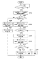
図3は、本実施形態において、サーバ装置102におけるMIBの変更処理手順の一例を示すフローチャートである。なお、図3に示す各処理は、制御部221の制御により行われる。以下の説明では、ネットワークカメラ103cをローパワーモードからハイパワーモードへ変更する第1のカメラとし、ネットワークカメラ103aをハイパワーモードからローパワーモードへ変更する第2のカメラとして説明する。
FIG. 3 is a flowchart showing an example of the MIB change processing procedure in the
まず、サーバ装置102はイベントの発生を検出するまで待機する(S301)。ここでは、第1のカメラの動作モードを消費電力の小さいローパワーモードから消費電力の大きいハイパワーモードへ変更するイベントが発生したことを検出するまで待機する。上記イベントを検出する方法としては、内部に設定されたタイマーや、外部からの操作等により検出する方法などが挙げられる。
First, the
S301でイベントを検出すると、ハブ登録テーブル205とMIB204とを参照してハブ101の給電能力を確認する(S302)。そして、第1のカメラがハイパワーモードであっても給電能力に余裕があるか否かを判断する(S303)。給電能力に余裕があり、給電可能と判断する条件としては、ハブ101に接続されている全てのネットワークカメラに対してハイパワーモードで給電可能な場合である。もしくは、第1のカメラへ電力を供給する優先順位が他の接続されているネットワークカメラがハイパワーモードとなっても大丈夫なランクに設定されている場合である。
When an event is detected in S301, the power supply capability of the
S303の判断の結果、給電能力に余裕がある場合は、第1のカメラに対してハイパワーモードへの移行を指示する指示コマンドをSNMPにより送信する(S304)。そして、MIB204の第1のカメラの情報要素の消費電力に該当する項目を変更する(S305)。
As a result of the determination in S303, if there is a surplus in power supply capacity, an instruction command for instructing the first camera to shift to the high power mode is transmitted by SNMP (S304). Then, the item corresponding to the power consumption of the information element of the first camera of the
一方、S302の判断の結果、給電能力に余裕がない場合は、MIB204を参照し、第1のカメラ以外でハイパワーモードに現在設定されており、かつ優先度がハイパワーモードに設定されているカメラを探索する。そして、このカメラをローパワーモードに落とす処理を行うことになる。以下の説明では、ローパワーモードの落とすカメラを第2のカメラとして説明する。
On the other hand, if the result of the determination in S302 is that there is no surplus power supply capability, the high power mode is currently set to other than the first camera with reference to the
S302の判断の結果、給電能力に余裕がない場合は、第1の指示として、サーバ装置102は第2のカメラに対してローパワーモードへ変更するとともに給電の優先順位を下げる指示コマンドをSNMPにより送信する(S306)。このとき、空いている順位であって、第1のカメラ以外のネットワークカメラが全てハイパワーモードになっても給電能力に支障が出ない優先順位を設定する。
As a first instruction, if the result of the determination in S302 is that there is no surplus in power supply capacity, the
図4は、本実施形態において、第2のカメラによる動作モードの変更処理手順の一例を示すフローチャートである。なお、図4に示す各処理は、制御部242の制御により行われる。
まず、第2のカメラはハイパワーモードで動作しており、図3のS306により送信された指示コマンドを受信するまで待機する(S401)。そして、第2のカメラがサーバ装置102からの指示コマンドを受信すると、ハブ101に対してLLDPによりローパワーモードの給電容量へ変更するととともに給電の優先順位を変更する変更要求を送信する(S402)。
FIG. 4 is a flowchart illustrating an example of a procedure for changing the operation mode by the second camera in the present embodiment. 4 is performed under the control of the
First, the second camera is operating in the high power mode, and waits until the instruction command transmitted in S306 of FIG. 3 is received (S401). When the second camera receives an instruction command from the
次に、ハブ101から応答を受信し、ハブ101からACK(変更OK)を受信したか否かを判断する(S403)。この判断の結果、ACKを受信した場合は、動作モードをローパワーモードに変更する(S404)。そして、自身のMIB207を変更し(S405)、ローパワーモードへの変更と給電の優先順位の変更とが完了した完了応答をSNMPでサーバ装置102へ送信する(S406)。このとき、ハブ101から第2のカメラに対して送られたコマンドに対する応答としてACKを送信する。
Next, a response is received from the
一方、S403の判断の結果、ハブ101からNACK(変更不可)を受信した場合は、ローパワーモードへの変更と給電の優先順位の変更とが失敗したことをSNMPでサーバ装置102へ送信する(S407)。このとき、ハブ101から第2のカメラに対して送られたコマンドに対する応答としてNACKを送信する。
On the other hand, if NACK (cannot be changed) is received from the
図3の説明に戻り、S306で第2のカメラに対して指示コマンドを送信した後、第2のカメラからの応答が図4のS406で送信するACKであるか否かを判断する(S307)。この判断の結果、第2のカメラからの応答が図4のS406で送信するACKではなく、S407で送信するNACKである場合は、エラー処理を実施する(S308)。上記エラー処理は画面上への表示、登録している管理者へのエラーメールの送信等が挙げられる。 Returning to the description of FIG. 3, after transmitting the instruction command to the second camera in S306, it is determined whether or not the response from the second camera is an ACK transmitted in S406 of FIG. 4 (S307). . As a result of this determination, if the response from the second camera is not the ACK transmitted in S406 of FIG. 4 but the NACK transmitted in S407, error processing is performed (S308). Examples of the error processing include display on the screen and transmission of an error mail to the registered administrator.
一方、S307の判断の結果、第2のカメラからの応答がACKである場合は、MIB204内の第2のカメラの情報要素を変更する(S309)。そして、第2の指示として、第1のカメラに対してハイパワーモードへ変更するとともに給電の優先順位を上げるように変更する指示コマンドをSNMPで送信する(S310)。そして、第1のカメラでは、図4に示した手順と同様に、ハブ101に対して動作モード及び変更を要求する。そして、ACKを受信した場合には、ACKをサーバ装置102に送信し、ハブ101からNACKを受信した場合には、NACKをサーバ装置102に送信する。
On the other hand, as a result of the determination in S307, if the response from the second camera is ACK, the information element of the second camera in the
次に、第1のカメラからの応答がACK応答であるか否かを判断する(S311)。この判断の結果、第1のカメラからの応答がNACK応答である場合は、エラー処理を実施する(S312)。S312におけるエラー処理は、S308におけるエラー処理と同等である。 Next, it is determined whether or not the response from the first camera is an ACK response (S311). If the result of this determination is that the response from the first camera is a NACK response, error processing is performed (S312). The error processing in S312 is equivalent to the error processing in S308.
S308のエラー処理は、ハブ101が第2のカメラに対する給電容量を下げるのを拒絶したことによって行われる処理である。これに対してS312のエラー処理が行われる条件は、ハイパワーモードで動作していた第2のカメラがローパワーモードに変更されていることが条件である。このことからハブ101は第1のカメラに対してハイパワーモードで給電可能である。それにもかかわらず、第1のカメラに対してハイパワーモードで給電することを拒絶するような場合には、S312のエラー処理が行われる。したがって、S312のエラー処理は通常は起こらないエラー処理である。
The error process of S308 is a process performed when the
一方、S311の判断の結果、第1のカメラからの応答がACK応答である場合は、MIB204内の第1のカメラの情報要素を変更する(S313)。S305での変更と異なる点は、S305では変更される項目がカメラの動作モードに応じた給電容量だけなのに対して、S313ではカメラの動作モードに応じた給電容量と給電の優先順位との2項目が変更される点である。
On the other hand, if the result of determination in S311 is that the response from the first camera is an ACK response, the information element of the first camera in the
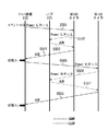
次に、第1のカメラをローパワーモードからハイパワーモードに変更する場合のシーケンス例について図5を参照しながら説明する。
第1のカメラの動作モードをローパワーモードからハイパワーモードへ変更するイベントが発生し、ハブ101側で給電能力に余裕がない場合は、以下のような処理が行われる。まず、第2のカメラをローパワーモードにする必要があるため、サーバ装置102は第2のカメラに対して動作モードをローパワーモードにして給電の優先順位を下位にする指示(Power:L/Pri:L)をSNMPのコマンドで送信する(S501)。この処理は、図3のS306に相当する処理である。
Next, a sequence example when the first camera is changed from the low power mode to the high power mode will be described with reference to FIG.
When an event for changing the operation mode of the first camera from the low power mode to the high power mode occurs and there is no surplus power supply capacity on the
S501によるコマンドを受信した第2のカメラは、ハブ101に対してLLDPを使用し、ローパワーモードの給電容量にして給電の優先順位を下位にする変更を要求する(S502)。この処理は、図4のS402に相当する処理である。S502で送信された変更要求を受信したハブ101は、通常は電力供給制御部211により給電容量及び給電の優先順位を変更してACKを返す(S503)。ACKを受信した第2のカメラは、S501によるコマンドに対しての完了応答としてSNMPによりACKを送信する(S504)。このS504の処理は、図4のS406に相当する処理である。
The second camera that has received the command in S501 uses LLDP to request the
次に、サーバ装置102は、第2のカメラからACK応答を受信すると、第1のカメラに対して動作モードをハイパワーモードにして給電の優先順位を上位にする指示(Power:H/Pri:H)をSNMPのコマンドで送信する(S505)。この処理は、図3のS310に相当する処理である。S505によるコマンドを受信した第1のカメラは、ハブ101に対してLLDPを使用し、ハイパワーモードの給電容量にして給電の優先順位を上位にする変更を要求する(S506)。S506で送信された変更要求を受信したハブ101は、通常は電力供給制御部211により給電容量及び給電の優先順位を変更してACKを返す(S507)。ACKを受信した第1のカメラは、S505によるコマンドに対しての完了応答としてSNMP上でACKを送信する(S508)。
Next, when the
次に、図5に示したシーケンスに従ったサーバ装置102内のMIB204の変更履歴について図6を参照しながら説明する。
図6に示すように、図5のシーケンスを開始する前の状態のMIB204では、第1のカメラはローパワーモードの給電容量で給電の優先順位が下位であり、第2のカメラはハイパワーモードの給電容量で給電の優先順位が上位である。
Next, the change history of the
As shown in FIG. 6, in the
第2のカメラから動作モードの切替完了の完了応答を受信すると、図3のS309でサーバ装置102はMIB204において第2のカメラの情報要素を変更する。したがって、図5の状態X1の段階では、第1のカメラ及び第2のカメラは、ともにローパワーモードの給電容量で給電の優先順位が下位である。
When the completion response of the operation mode switching completion is received from the second camera, the
この後、第1のカメラから動作モードの切替完了の完了応答を受信すると、図3のS313で第1のカメラの情報要素を変更する。したがって、図5の状態X2の段階でMIB204の内容は、第1のカメラはハイパワーモードの給電容量で給電の優先順位が上位となり、第2のカメラはローパワーモードの給電容量で給電の優先順位が下位となる。
Thereafter, when a completion response indicating completion of switching of the operation mode is received from the first camera, the information element of the first camera is changed in S313 of FIG. Accordingly, in the state X 2 in FIG. 5, the content of the
図7は、ハブ101の管理テーブル201の構成例を示す図である。図7に示すように、管理テーブル201にはポート番号ごとにPower Class(給電容量)とPriority(優先順位)とが設定されている。この管理テーブル201も、第1のカメラ及び第2のカメラからの変更要求を受信し、ACKを返した段階でそれぞれ変更される。
FIG. 7 is a diagram illustrating a configuration example of the management table 201 of the
以上のように本実施形態によれば、動作モードに応じた給電容量を変更するとともに給電の優先順位も変更することにより、第1のカメラのハイパワーモードでの動作を保障することができる。 As described above, according to the present embodiment, the operation of the first camera in the high power mode can be ensured by changing the power supply capacity according to the operation mode and changing the priority of power supply.
(第2の実施形態)
以下、図1、図6、及び図7〜図10を参照して、本発明の第2の実施形態におけるPoEの給電容量の切替制御及び給電優先順位の変更制御について説明する。なお、本実施形態におけるネットワークカメラシステム及びプロトコルスタックの構成についてはそれぞれ図1及び図2と同様であるため、説明は省略する。また、以下の説明では、ネットワークカメラ103cをローパワーモードからハイパワーモードへ変更する第1のカメラとし、ネットワークカメラ103aをハイパワーモードからローパワーモードへ変更する第2のカメラとして説明する。
(Second Embodiment)
Hereinafter, with reference to FIGS. 1, 6, and 7 to 10, the switching control of the feeding capacity of PoE and the changing control of the feeding priority in the second embodiment of the present invention will be described. Note that the configurations of the network camera system and the protocol stack in this embodiment are the same as those in FIGS. In the following description, the
図8は、本実施形態において、第1のカメラにおける動作モードの変更処理手順の一例を示すフローチャートである。なお、図8に示す各処理は、制御部242の制御により行われる。
まず、第1のカメラはハイパワーモードへ切り替えるイベントが発生するまで待機する(S801)。なお、上記イベントは内部に設定されたタイマー、動き検出等の設定されているトリガー等が挙げられる。そして、イベントが発生すると、ハブ101に対してローパワーモードの給電容量からハイパワーモードの給電容量に変更するようにLLDPを使用して変更要求を送信する(S802)。
FIG. 8 is a flowchart illustrating an example of a procedure for changing the operation mode in the first camera in the present embodiment. 8 is performed under the control of the
First, the first camera stands by until an event for switching to the high power mode occurs (S801). The event includes a timer set inside, a trigger set for motion detection, and the like. When an event occurs, a change request is transmitted to the
次に、ハブ101から応答を受信し、ハブ101から給電容量の切替完了を示すACKを受信したか否かを判断する(S803)。この判断の結果、ACKを受信した場合は、第2のカメラは動作モードをローパワーモードからハイパワーモードへ変更する(S804)。そして、サーバ装置102へSNMPを使用して動作モードを変更した旨を送信する(S805)。これにより、サーバ装置102では、MIB204内の第1のカメラの情報要素を変更することになる。
Next, a response is received from the
一方、S803の判断の結果、ハブ101からNACK(切替不可)を受信した場合は、サーバ装置102に対してSNMPを使用してローパワーモードからハイパワーモードへの変更要求を送信する(S806)。
On the other hand, if NACK (cannot be switched) is received from the
図9は、本実施形態において、サーバ装置102におけるMIBの変更処理手順の一例を示すフローチャートである。なお、図9に示す各処理は、制御部221の制御により行われる。
まず、図8のS806の処理により第1のカメラから変更要求を受信するまで待機する(S901)。変更要求を受信すると、サーバ装置102はMIB204を参照する(S902)。そして、第1のカメラ以外で、ハイパワーモードで現在動作していてローパワーモードに変更可能なカメラの有無を確認する(S903)。この確認の結果、ローパワーモードに変更可能なカメラが存在しない場合は、第1のカメラに対して変更不可を示すNACKを送信する(S904)。この場合、第1のカメラはハイパワーモードへ変更することができない。
FIG. 9 is a flowchart illustrating an example of the MIB change processing procedure in the
First, it waits until a change request is received from the first camera by the processing of S806 in FIG. 8 (S901). When receiving the change request, the
一方、S903の確認の結果、ローパワーモードへ変更可能なカメラが存在する場合は、第1の指示として、サーバ装置102は第2のカメラに対してローパワーモードへの変更と給電の優先順位の変更とを指示する指示コマンドをSNMPで送信する(S905)。このとき、空いている順位であって、第1のカメラ以外のカメラが全てハイパワーモードになっても給電能力に支障が出ない優先順位を設定する。なお、第2のカメラにおける動作モード及び給電の優先順位の変更手順は図4と同様であるため、説明は省略する。
On the other hand, if there is a camera that can be changed to the low power mode as a result of the confirmation in S903, the
次に、第2のカメラから応答を受信し、動作モード及び給電の優先順位を変更したことを示すACKを受信したか否かを判断する(S906)。この判断の結果、第2のカメラからNACKを受信した場合は、エラー処理を行う(S907)。上記エラー処理は、画面上への表示、登録している管理者へのエラーメールの送信等が挙げられる。 Next, a response is received from the second camera, and it is determined whether or not an ACK indicating that the operation mode and power feeding priority has been changed has been received (S906). As a result of this determination, if NACK is received from the second camera, error processing is performed (S907). Examples of the error processing include display on a screen and transmission of an error mail to a registered administrator.
一方、S906の判断の結果、第2のカメラからACKを受信した場合は、ハブ101では第2のカメラの動作モードに係る給電容量及び給電の優先順位の変更が完了していることになる。したがって、サーバ装置102はMIB204内の第2のカメラの情報要素を変更する(S908)。そして、第2の指示として、第1のカメラに対してハイパワーモードへの変更と給電の優先順位の変更とを許可する指示コマンドとしてACKをSNMPにより送信する(S909)。
On the other hand, as a result of the determination in S906, when ACK is received from the second camera, the
図8の説明に戻り、S806でサーバ装置102に変更要求を送信した後、サーバ装置102からの応答が、図9のS909で送信するACKであるか否かを判断する(S807)。この判断の結果、サーバ装置102からの応答が、図9のS909で送信するACKではなく図9のS904で送信するNACKである場合は、ハイパワーモードへの変更ができないため、処理を終了する。
Returning to the description of FIG. 8, after transmitting the change request to the
一方、S807の判断の結果、サーバ装置102からの応答が図9のS909で送信するACKである場合は、第1のカメラは、ハブ101にハイパワーモードの給電容量への変更と給電の優先順位の変更とを要求する変更要求をLLDPで送信する(S808)。そして、ハブ101からの応答がACKであるか否かを判断する(S809)。この判断の結果、NACKである場合は、第1のカメラはサーバ装置102へ変更不可の応答としてNACKを送信する(S810)。
On the other hand, as a result of the determination in S807, if the response from the
一方、S809の判断の結果、ハブ101からの応答がACKである場合は、第1のカメラは動作モードをハイパワーモードに変更するとともに自身のMIB207を更新する(S811)。そして、サーバ装置102へ動作モードの切替が完了した完了応答としてACKを送信する(S812)。なお、S805では、動作モードのみを変更内容としてサーバ装置102に送信するのに対し、S812では、動作モード及び給電の優先順位の変更内容をサーバ装置102に送信する。
On the other hand, as a result of the determination in S809, if the response from the
再び図9の説明に戻り、S909で第1のカメラに指示コマンドを送信した後、指示コマンドに対する応答を受信し、この応答が図8のS812で送信するACKであるか否かを判断する(S910)。この判断の結果、図8のS812で送信するACKではなく、図8のS810で送信するNACKである場合は、エラー処理を行う(S911)。このエラー処理はS907のエラー処理と同様である。一方、S910の判断の結果、図8のS812で送信するACKである場合は、サーバ装置102はMIB204内の第1のカメラの情報要素を変更する(S912)。
Returning to the description of FIG. 9 again, after an instruction command is transmitted to the first camera in S909, a response to the instruction command is received, and it is determined whether this response is an ACK transmitted in S812 of FIG. S910). As a result of this determination, if it is not the ACK transmitted in S812 of FIG. 8 but the NACK transmitted in S810 of FIG. 8, error processing is performed (S911). This error processing is the same as the error processing in S907. On the other hand, as a result of the determination in S910, if the ACK is transmitted in S812 of FIG. 8, the
次に、第1のカメラからの起動によりローパワーモードからハイパワーモードに変更する場合のシーケンス例について図10を参照しながら説明する。以下の説明では、ハブ101側で給電能力に余裕がない状況を前提として説明する。
第1のカメラにおいて動作モードをローパワーモードからハイパワーモードへ変更するイベントが発生した場合、第1のカメラはハブ101に対してハイパワーモードの給電容量へ変更する変更要求(Power:H)をLLDPにより送信する(S1001)。この処理は、図8のS802に相当する処理である。
Next, a sequence example in the case of changing from the low power mode to the high power mode by activation from the first camera will be described with reference to FIG. The following description will be made on the assumption that there is no surplus power supply capacity on the
When an event for changing the operation mode from the low power mode to the high power mode occurs in the first camera, the first camera requests the
次に、ハブ101は給電能力に余裕がないため、第1のカメラに拒否を示すNACKを送信する(S1002)。そこで、他のネットワークカメラをローパワーモードにするために、第1のカメラは、サーバ装置102にハイパワーモードへの変更要求を送信する(S1003)。この処理は、図8のS806に相当する処理である。
Next, since the
一方、サーバ装置102は、第2のカメラに対してローパワーモードへ変更するとともに給電の優先順位を下位に変更する指示(Power:L/Pri:L)をSNMPのコマンドで送信する(S1004)。この処理は、図9のS905に相当する処理である。S1004により送信されたコマンドを受信した第2のカメラは、ハブ101に対してLLDPを使用してローパワーモードの給電容量へ変更するとともに給電の優先順位を下位に変更するよう変更要求を送信する(S1005)。S1005で送信された変更要求を受信したハブ101は、通常は電力供給制御部211により給電容量及び給電の優先順位を変更してACKを返す(S1006)。そして、ACKを受信した第2のカメラは、S1004で送信されたコマンドに対する完了応答として、SNMP上でACKをサーバ装置102に送信する(S1007)。
On the other hand, the
サーバ装置102は、第2のカメラからACKを受信すると、第1のカメラに対してハイパワーモードに変更するとともに給電の優先順位を上位にすることを指示するコマンドとしてSNMPによりACKを送信する(S1008)。この処理は、図9のS909に相当する処理である。
When the
サーバ装置102からACKを受信すると、第1のカメラは、ハブ101に対してLLDPを使用してハイパワーモードの給電容量に変更するとともに給電の優先順位を上位にする変更要求を送信する(S1009)。この処理は、図8のS808に相当する処理である。そして、S1009で送信された変更要求を受信したハブ101は、通常は電力供給制御部211により給電容量及び給電の優先順位を変更してACKを返す(S1010)。ハブ101からACKを受信した第1のカメラは、S1008で送信されたコマンドに対する完了応答としてSNMP上でACKをサーバ装置102に送信する(S1011)。この処理は、図8のS812に相当する処理である。
When the ACK is received from the
次に、図10に示したシーケンスに対するサーバ装置102内のMIB204の変更履歴について説明する。
図10のシーケンスを開始する前の状態のMIB204では、第1のカメラは、ローパワーモードの給電容量で給電の優先順位が下位であり、第2のカメラは、ハイパワーモードの給電容量で給電の優先順位が上位である。
Next, a change history of the
In the
第2のカメラから動作モードの切替の完了応答を受信すると、図9のS908でサーバ装置102は第2のカメラの情報要素を変更する。したがって、図10の状態X1'の段階では、第1のカメラ及び第2のカメラは、ともにローパワーモードの給電容量で給電の優先順位が下位である。
When the completion response for switching the operation mode is received from the second camera, the
この後、第1のカメラから動作モードの切替の完了応答を受信すると、図9のS912でサーバ装置102は第1のカメラの情報要素を変更する。したがって、図10の状態X2'の段階でMIB204の内容は、第1のカメラはハイパワーモードの給電容量で給電の優先順位が上位となり、第2のカメラはローパワーモードの給電容量で宮殿の優先順位が下位となる。
Thereafter, when an operation mode switching completion response is received from the first camera, the
以上のように本実施形態によれば、動作モードに応じた給電容量を変更するとともに給電の優先順位も変更することにより、第1のカメラのハイパワーモードでの動作を保障することができる。 As described above, according to the present embodiment, the operation of the first camera in the high power mode can be ensured by changing the power supply capacity according to the operation mode and changing the priority of power supply.
(第3の実施形態)
以下、図11〜図15を参照して、本発明の第3の実施形態におけるPoEの給電容量の切替制御及び給電の優先順位の変更制御について説明する。なお、本実施形態においては、図1と同様のネットワークカメラシステムの構成例であるため、その説明は省略する。
(Third embodiment)
Hereinafter, PoE power supply capacity switching control and power supply priority change control according to the third embodiment of the present invention will be described with reference to FIGS. In this embodiment, the configuration example of the network camera system is the same as that shown in FIG.
図11は、本実施形態に係るネットワークカメラシステムの内部構成例を示すブロック図である。なお、図2と重複する構成については説明を省略し、図2と異なる点について説明する。
図11において、サーバ装置1102は、ネットワークカメラの動作モードとその動作モードに対応した消費電力(給電容量)とを登録するカメラ登録テーブル1101を記憶部222に記憶している。
FIG. 11 is a block diagram illustrating an internal configuration example of the network camera system according to the present embodiment. Note that a description of the same components as those in FIG. 2 is omitted, and only differences from FIG. 2 will be described.
In FIG. 11, the
図14は、カメラ登録テーブル1101の一例を示す図である。本実施形態では、ネットワークカメラとしてカメラi、カメラk及びカメラnがネットワークカメラシステムに接続されている例について説明する。
カメラi、カメラk及びカメラnはモード1〜3へ動作モードを設定することが可能である。ここで、図14に示すように、カメラiのモード1、2、3に対応する消費電力(給電容量)をそれぞれA、B、Cとする。同様に、カメラkのモード1、2、3に対応する消費電力(給電容量)をそれぞれD、E、Fとし、カメラnのモード1、2、3に対応する消費電力(給電容量)をそれぞれX、Y、Zとする。また、カメラi、カメラk及びカメラnはともにモード1、2、3の順序でハブ101の給電容量が小さくなり、給電容量の関係では、以下の式(1)かつ式(2)の条件を満たすものとする。
A>B>C、D>E>F、X>Y>Z ・・・(1)
(X−Z)>(A−B)、(X−Z)>(D−E)、(X−Z)<(A−B)+(D−E) ・・・(2)
FIG. 14 is a diagram illustrating an example of the camera registration table 1101. In the present embodiment, an example will be described in which a camera i, a camera k, and a camera n are connected to a network camera system as network cameras.
The camera i, the camera k, and the camera n can set the operation mode to
A>B> C, D>E> F, X>Y> Z (1)
(X−Z)> (A−B), (X−Z)> (D−E), (X−Z) <(A−B) + (D−E) (2)
本実施形態においては、カメラnをモード3からモード1へ変更し、カメラi及びカメラkをモード1からモード2へ変更する例について説明する。
In the present embodiment, an example in which the camera n is changed from mode 3 to
図12は、本実施形態において、サーバ装置1102におけるMIBの変更処理手順の一例を示すフローチャートである。なお、図12に示す各処理は、制御部221の制御により行われる。
まず、サーバ装置1102はイベントの発生を検出するまで待機する(S1201)。ここでは、カメラnの動作モードをモード3からモード1へ変更するイベントの待ち状態となる。上記イベントを検出する方法としては、内部に設定されたタイマーや、外部からの操作等により検出する方法などが挙げられる。
FIG. 12 is a flowchart illustrating an example of the MIB change processing procedure in the
First, the
S1201でイベントの発生を検出すると、ハブ登録テーブル205とMIB204とを参照してハブ101の給電能力を確認する(S1202)。そして、カメラnがモード1であっても給電能力に余裕があるか否かを判断する(S1203)。給電能力に余裕があり、給電可能と判断する条件としては、ハブ101に接続されている全てのネットワークカメラに対してモード1で給電可能な場合である。もしくは、カメラnの給電の優先順位が他の接続されているネットワークカメラがモード1となっても大丈夫なランクに設定されている場合である。
When the occurrence of an event is detected in S1201, the power supply capability of the
S1203の判断の結果、給電能力に余裕がある場合は、カメラnに対してSNMPコマンドを使用してモード1への移行を指示する指示コマンドを送信する(S1204)。そして、MIB204のカメラnの情報要素を変更する(S1205)。
As a result of the determination in S1203, if there is a margin in the power supply capability, an instruction command for instructing the shift to
一方、S1203の判断の結果、給電能力に余裕がない場合は、MIB204とカメラ登録テーブル1101とを参照する(S1206)。そして、カメラn以外でモード1又はモード2に設定されていて、かつ優先度がカメラnよりも上位に設定されているネットワークカメラ、すなわち設定変更が可能なネットワークカメラが存在するか否かを判断する(S1207)。
On the other hand, as a result of the determination in S1203, when there is no surplus power supply capability, the
S1207の判断の結果、設定変更が可能なネットワークカメラが存在しない場合、或いは変更してもカメラnがモード1に移行できない場合は、カメラnに対して、動作モードの変更ができないことを示す応答としてNACKを返す(S1208)。この場合、カメラnでは動作モードの変更が行わないことになる。
As a result of the determination in S1207, if there is no network camera that can change the setting, or if camera n cannot be shifted to
一方、S1207の判断の結果、設定変更が可能なネットワークカメラが存在する場合は、このネットワークカメラを現状よりも消費電力の低い動作モードに落とす処理を行うことになる。そこで、カメラi及びカメラkをそれぞれモード1からモード2に変更するカメラとして選定する(S1209)。次に、第1の指示として、サーバ装置1102はカメラi及びカメラkそれぞれに対して、動作モードをモード1からモード2へ変更するとともに給電の優先順位を変更する指示コマンドをSNMPにより送信する(S1210)。このとき、空いている順位であって、カメラn以外のネットワークカメラが全てモード1になっても給電能力に支障が出ない優先順位を設定する。
On the other hand, if there is a network camera whose setting can be changed as a result of the determination in S1207, processing for dropping the network camera into an operation mode with lower power consumption than the current state is performed. Therefore, the camera i and the camera k are each selected as a camera that changes from
S1210の処理が行われる時点では、カメラi及びカメラkはそれぞれモード1で動作し、コマンド待ち状態である。カメラi及びカメラkは、サーバ装置1102からモード1からモード2への指示コマンドを受信すると、制御部242によりハブ101に対してLLDPによりそれぞれの消費電力に該当する値への給電容量の変更と給電の優先順位の変更とを要求する。
At the time when the process of S1210 is performed, the camera i and the camera k operate in
そして、ハブ101からACK(変更OK)を受信した場合は、動作モードをモード2に変更するとともに、自身のMIB207を変更する。さらに、動作モード及び給電の優先順位の変更が完了したことを示す完了応答としてSNMPでサーバ装置1102へACKを送信する。一方、ハブ101からNACK(変更不可)を受信した場合は、動作モード及び給電の優先順位の変更が失敗したことを示すNACKをSNMPでサーバ装置1102へ送信する。
When ACK (change OK) is received from the
サーバ装置1102は、S1210により指示コマンドをカメラi及びカメラkに送信した後にそれぞれのカメラから応答を受信し、いずれも応答がACKであるか否かを判断する(S1211)。この判断の結果、少なくとも何れかからNACKを受信した場合は、エラー処理を実施する(S1212)。上記エラー処理は、画面上への表示、登録している管理者へのエラーメールの送信等が挙げられる。
The
一方、S1211の判断の結果、いずれも応答がACKである場合は、MIB204内のカメラi及びカメラkの情報要素を変更する(S1213)。そして、第2の指示として、カメラnに対してモード1へ変更するとともに給電の優先順位を上位へ変更する指示コマンドをSNMPで送信する(S1214)。
On the other hand, as a result of the determination in S1211, if both responses are ACK, the information elements of the camera i and camera k in the
カメラnでは、S1214により送信された指示コマンドを受信すると、前述したカメラi及びカメラkと同様の手順によりハブ101に変更要求を行い、その応答結果に応じてサーバ装置1102にACKまたはNACKを送信する。
Upon receiving the instruction command transmitted in S1214, the camera n issues a change request to the
サーバ装置1102は、カメラnから応答を受信し、応答がACKであったか否かを判断する(S1215)。この判断の結果、応答がNACKである場合は、エラー処理を実施する(S1216)。なお、S1216におけるエラー処理は、S1212におけるエラー処理と同等である。
The
一方、S1215の判断の結果、応答がACKである場合は、MIB204内のカメラnの情報要素を変更する(S1217)。S1205での変更と異なる点は、S1205では変更される項目がカメラの動作モードに応じた給電容量だけなのに対して、S1217ではカメラの動作モードに応じた給電容量と給電の優先順位との2項目が変更される点である。
On the other hand, as a result of the determination in S1215, if the response is ACK, the information element of the camera n in the
次に、カメラnをモード3からモード1に変更する場合のシーケンス例について図13を参照しながら説明する。
カメラnの動作モードをモード3からモード1へ変更するイベントが発生し、ハブ101側で給電能力に余裕がない場合は、以下のような処理が行われる。まず、カメラi及びカメラkをそれぞれモード1からモード2に変更する必要がある。そこで、サーバ装置1102はカメラi及びカメラkに対して動作モードをモード2に変更するとともに給電の優先順位を下位にする指示(Mode2/Pri:L)をSNMPのコマンドで送信する(S1301及びS1302)。この処理は、図12のS1210に相当する処理である。
Next, a sequence example when the camera n is changed from mode 3 to
When an event for changing the operation mode of the camera n from the mode 3 to the
S1301によるコマンドを受信したカメラiは、ハブ101に対してLLDPを使用し、モード2の給電容量(B)に変更するとともに給電の優先順位を下位に変更する変更要求(Power:B/Pri:L2)を送信する(S1303)。なお、L2の"2"は、単に移行した順序で付されているものである。S1303で送信された変更要求を受信したハブ101は、通常は電力供給制御部211により給電容量及び給電の優先順位を変更してACKを返す(S1304)。
The camera i that has received the command in S1301 uses LLDP for the
さらに、S1302によるコマンドを受信したカメラkは、ハブ101に対してLLDPを使用し、モード2の給電容量(E)に変更するとともに給電の優先順位を下位に変更する変更要求(Power:E/Pri:L3)を送信する(S1305)。S1305で送信された変更要求を受信したハブ101は、通常は電力供給制御部211により給電容量及び給電の優先順位を変更してACKを返す(S1306)。
Further, the camera k that has received the command in S1302 uses LLDP for the
次に、ACKを受信したカメラiは、S1301により送信されたコマンドに対する完了応答として、SNMP上でACKをサーバ装置1102に送信する(S1307)。さらにACKを受信したカメラkは、S1302により送信されたコマンドに対する完了応答としてSNMP上でACKをサーバ装置1102に送信する(S1308)。
Next, the camera i that has received ACK transmits ACK to the
次に、サーバ装置1102は、カメラi及びカメラkからACKを受信すると、カメラnに対して動作モードをモード1に変更するとともに給電の優先順位を上位にする指示(Mode1/Pri:H0)をSNMPのコマンドで送信する(S1309)。
Next, when receiving an ACK from the camera i and the camera k, the
S1309によるコマンドを受信したカメラnは、ハブ101に対してLLDPを使用し、モード1の給電容量(X)に変更するとともに給電の優先順位を上位に変更する変更要求(Power:X/Pri:H0)を送信する(S1310)。S1310で送信された変更要求を受信したハブ101は、通常は電力供給制御部211により給電容量及び給電の優先順位を変更してACKを返す(S1311)。ACKを受信したカメラnは、S1309により送信されたコマンドに対する完了応答としてSNMP上でACKをサーバ装置1102に送信する(S1312)。
The camera n that has received the command in step S1309 uses LLDP for the
次に、図13に示したシーケンスに従ったサーバ装置1102内のMIB204の変更履歴について図15を参照しながら説明する。
図15に示すように、図13のシーケンスを開始する前の状態のMIB204の内容は、以下の通りである。すなわち、カメラiはモード1で動作しており、給電容量はAで給電の優先順位は上位のH1であり、カメラkはモード1で動作しており、給電容量はDで給電の優先順位は上位のH2である。また、カメラnはモード3で動作しており、給電容量はZで給電の優先順位は下位のL1である。
Next, the change history of the
As shown in FIG. 15, the contents of the
カメラiから動作モードの切替完了の完了応答を受信すると、図12のS1213でサーバ装置1102はMIB204においてカメラiの情報要素を変更する。したがって、図13の状態Y1の段階では、カメラiはモード2で動作し、給電容量はBで給電の優先順位は下位のL2となる。
When a completion response indicating that the operation mode has been switched is received from the camera i, the
さらに、カメラkから動作モードの切替完了の完了応答を受信すると、図12のS1213でサーバ装置1102はMIB204においてカメラkの情報要素を変更する。したがって、図13の状態Y2の段階では、カメラkはモード2で動作し、給電容量はEで給電の優先順位は下位のL3となる。
Further, when the completion response of the operation mode switching completion is received from the camera k, the
この後、カメラnから動作モードの切替完了の完了応答を受信すると、図12のS1217でサーバ装置1102はMIB204においてカメラnの情報要素を変更する。したがって、図13の状態Y3の段階では、MIB204の内容は、以下の通りである。すなわち、カメラiはモード2で動作しており、給電容量はBで給電の優先順位は下位のL1であり、カメラkはモード2で動作しており、給電容量はEで給電の優先順位は下位のL2である。また、カメラnはモード1で動作し、給電容量はXで給電の優先順位は上位のH0となる。
Thereafter, when a completion response indicating the completion of the operation mode switching is received from the camera n, the
以上のように本実施形態によれば、動作モードに応じた給電容量に変更するとともに給電の優先順位も変更することにより、カメラnのモード1での動作を保障することができる。
As described above, according to the present embodiment, the operation in the
(その他の実施形態)
また、本発明は、以下の処理を実行することによっても実現される。即ち、上述した実施形態の機能を実現するソフトウェア(プログラム)を、ネットワーク又は各種記憶媒体を介してシステム或いは装置に供給し、そのシステム或いは装置のコンピュータ(またはCPUやMPU等)がプログラムを読み出して実行する処理である。
(Other embodiments)
The present invention can also be realized by executing the following processing. That is, software (program) that realizes the functions of the above-described embodiments is supplied to a system or apparatus via a network or various storage media, and a computer (or CPU, MPU, or the like) of the system or apparatus reads the program. It is a process to be executed.
204 MIB
205 ハブ登録テーブル
221 制御部
222 記憶部
204 MIB
205 Hub registration table 221
Claims (7)
前記複数のネットワークカメラの中の第1のカメラの動作モードをより消費電力の大きいモードに変更する場合の前記ハブの給電能力を判断する判断手段と、
前記判断手段による判断の結果、前記ハブの給電能力を超える場合に、前記複数のネットワークカメラの中の第2のカメラに対して動作モードをより消費電力の小さいモードへ変更するよう指示する第1の指示手段と、
前記第1の指示手段による指示に応じて前記第2のカメラの動作モードが変更された後に、前記第1のカメラに対して動作モードをより消費電力の大きいモードに変更するよう指示する第2の指示手段と、
前記第1の指示手段による指示に応じて前記第2のカメラの動作モードが変更された旨、及び前記第2の指示手段による指示に応じて前記第1のカメラの動作モードが変更された旨の情報を受信する受信手段とを有することを特徴とするシステム制御装置。 A system controller connected to a plurality of network cameras and a hub for supplying power to the network cameras,
Determining means for determining the power supply capability of the hub when the operation mode of the first camera among the plurality of network cameras is changed to a mode with higher power consumption;
If the result of determination by the determination means is that the power supply capacity of the hub is exceeded, a second camera of the plurality of network cameras is instructed to change the operation mode to a mode with lower power consumption. Instruction means,
A second instruction that instructs the first camera to change the operation mode to a mode with higher power consumption after the operation mode of the second camera is changed in accordance with an instruction from the first instruction means; Instruction means,
The fact that the operation mode of the second camera has been changed in response to an instruction from the first instruction means, and that the operation mode of the first camera has been changed in response to an instruction from the second instruction means And a receiving unit for receiving the information.
前記判断手段は、前記管理手段により管理された情報に基づいて前記ハブの給電能力を判断することを特徴とする請求項1〜3の何れか1項に記載のシステム制御装置。 Management means for managing information on the power supply capacity of the hub and power supply priority for the plurality of network cameras;
The system control device according to claim 1, wherein the determination unit determines a power supply capability of the hub based on information managed by the management unit.
前記複数のネットワークカメラの中の第1のカメラの動作モードをより消費電力の大きいモードに変更する場合の前記ハブの給電能力を判断する判断工程と、
前記判断工程における判断の結果、前記ハブの給電能力を超える場合に、前記複数のネットワークカメラの中の第2のカメラに対して動作モードをより消費電力の小さいモードへ変更するよう指示する第1の指示工程と、
前記第1の指示工程における指示に応じて前記第2のカメラの動作モードが変更された後に、前記第1のカメラに対して動作モードをより消費電力の大きいモードに変更するよう指示する第2の指示工程と、
前記第1の指示工程における指示に応じて前記第2のカメラの動作モードが変更された旨、及び前記第2の指示工程における指示に応じて前記第1のカメラの動作モードが変更された旨の情報を受信する受信工程とを有することを特徴とするシステム制御方法。 A system control method for a plurality of network cameras and a system control device connected via a hub for supplying power to the network cameras,
A determination step of determining the power supply capability of the hub when the operation mode of the first camera among the plurality of network cameras is changed to a mode with higher power consumption;
If the result of determination in the determination step is that the power supply capacity of the hub is exceeded, a second camera of the plurality of network cameras is instructed to change the operation mode to a mode with lower power consumption. The instruction process of
A second instruction that instructs the first camera to change the operation mode to a mode with higher power consumption after the operation mode of the second camera is changed according to the instruction in the first instruction step. The instruction process of
The fact that the operation mode of the second camera has been changed according to the instruction in the first instruction step, and the fact that the operation mode of the first camera has been changed in accordance with the instruction in the second instruction step And a receiving step of receiving the information.
前記複数のネットワークカメラの中の第1のカメラの動作モードをより消費電力の大きいモードに変更する場合の前記ハブの給電能力を判断する判断工程と、
前記判断工程における判断の結果、前記ハブの給電能力を超える場合に、前記複数のネットワークカメラの中の第2のカメラに対して動作モードをより消費電力の小さいモードへ変更するよう指示する第1の指示工程と、
前記第1の指示工程における指示に応じて前記第2のカメラの動作モードが変更された後に、前記第1のカメラに対して動作モードをより消費電力の大きいモードに変更するよう指示する第2の指示工程と、
前記第1の指示工程における指示に応じて前記第2のカメラの動作モードが変更された旨、及び前記第2の指示工程における指示に応じて前記第1のカメラの動作モードが変更された旨の情報を受信する受信工程とをコンピュータに実行させることを特徴とするプログラム。 A program for controlling a plurality of network cameras and a system control device connected via a hub for supplying power to the network cameras,
A determination step of determining the power supply capability of the hub when the operation mode of the first camera among the plurality of network cameras is changed to a mode with higher power consumption;
If the result of determination in the determination step is that the power supply capacity of the hub is exceeded, a second camera of the plurality of network cameras is instructed to change the operation mode to a mode with lower power consumption. The instruction process of
A second instruction that instructs the first camera to change the operation mode to a mode with higher power consumption after the operation mode of the second camera is changed according to the instruction in the first instruction step. The instruction process of
The fact that the operation mode of the second camera has been changed according to the instruction in the first instruction step, and the fact that the operation mode of the first camera has been changed in accordance with the instruction in the second instruction step A program for causing a computer to execute a receiving step for receiving the information.
Priority Applications (1)
| Application Number | Priority Date | Filing Date | Title |
|---|---|---|---|
| JP2011249964A JP2013105394A (en) | 2011-11-15 | 2011-11-15 | System control device, system control method, and program |
Applications Claiming Priority (1)
| Application Number | Priority Date | Filing Date | Title |
|---|---|---|---|
| JP2011249964A JP2013105394A (en) | 2011-11-15 | 2011-11-15 | System control device, system control method, and program |
Publications (1)
| Publication Number | Publication Date |
|---|---|
| JP2013105394A true JP2013105394A (en) | 2013-05-30 |
Family
ID=48624865
Family Applications (1)
| Application Number | Title | Priority Date | Filing Date |
|---|---|---|---|
| JP2011249964A Pending JP2013105394A (en) | 2011-11-15 | 2011-11-15 | System control device, system control method, and program |
Country Status (1)
| Country | Link |
|---|---|
| JP (1) | JP2013105394A (en) |
Cited By (3)
| Publication number | Priority date | Publication date | Assignee | Title |
|---|---|---|---|---|
| JP2020068496A (en) * | 2018-10-26 | 2020-04-30 | 池上通信機株式会社 | Id display device and video information display system |
| JP2021141395A (en) * | 2020-03-04 | 2021-09-16 | 株式会社明電舎 | Power supply control system |
| CN116155249A (en) * | 2023-04-20 | 2023-05-23 | 深圳市兆兴博拓科技股份有限公司 | Drive circuit of beauty mask, beauty mask and use method |
-
2011
- 2011-11-15 JP JP2011249964A patent/JP2013105394A/en active Pending
Cited By (8)
| Publication number | Priority date | Publication date | Assignee | Title |
|---|---|---|---|---|
| JP2020068496A (en) * | 2018-10-26 | 2020-04-30 | 池上通信機株式会社 | Id display device and video information display system |
| JP7163138B2 (en) | 2018-10-26 | 2022-10-31 | 池上通信機株式会社 | ID display and video information display system |
| JP2021141395A (en) * | 2020-03-04 | 2021-09-16 | 株式会社明電舎 | Power supply control system |
| JP2021141807A (en) * | 2020-03-04 | 2021-09-16 | 株式会社明電舎 | Power supply device |
| JP7099576B2 (en) | 2020-03-04 | 2022-07-12 | 株式会社明電舎 | Power supply device |
| JP7419882B2 (en) | 2020-03-04 | 2024-01-23 | 株式会社明電舎 | Power supply control system |
| CN116155249A (en) * | 2023-04-20 | 2023-05-23 | 深圳市兆兴博拓科技股份有限公司 | Drive circuit of beauty mask, beauty mask and use method |
| CN116155249B (en) * | 2023-04-20 | 2023-08-11 | 深圳市兆兴博拓科技股份有限公司 | Drive circuit of beauty mask, beauty mask and use method |
Similar Documents
| Publication | Publication Date | Title |
|---|---|---|
| JP6217731B2 (en) | Data processing system and data processing method | |
| EP3142343B1 (en) | Communication system, image forming apparatus and method of controlling the same, and storage medium | |
| CN105847317B (en) | Data processing apparatus, data processing system, data processing method, and storage medium | |
| US9210732B2 (en) | Wireless communication device registration in a wireless network | |
| JP2012063944A (en) | Printing system, control method, client terminal, print server, and program | |
| JP2009239870A (en) | Communication apparatus, control method therefor, program, and storage medium | |
| JP2015106798A (en) | Communication device, communication system, control method and program of communication device | |
| US20150092764A1 (en) | Communication apparatus, data processing apparatus, control method thereof, and recording medium | |
| JP2014063404A (en) | Image forming system, recovery method of image forming apparatus from power-saving state in the system, and image forming apparatus | |
| JP2013171420A (en) | Management system, image forming apparatus, control method for image forming apparatus, and program | |
| CN108234208A (en) | The visualization load balancing dispositions method and system of resource management based on business | |
| JP2017016373A (en) | Information processing apparatus, control method, and program | |
| JP2013105394A (en) | System control device, system control method, and program | |
| EP2919125A1 (en) | Information processing apparatus, method of controlling the same, and program | |
| JP2009208430A (en) | Image forming apparatus, system, method and program | |
| JP5171392B2 (en) | Communication system, information holding device, and management device | |
| JP2013121082A (en) | Printing system, image formation device, control method thereof and program | |
| JP7604152B2 (en) | COMMUNICATION DEVICE, CONTROL METHOD FOR COMMUNICATION DEVICE, AND PROGRAM | |
| JP2014127915A (en) | Display control device, control method and program | |
| CN114157606B (en) | Virtual network element device switching method, device and storage medium | |
| JP5446928B2 (en) | Power saving control of network system | |
| JP5445690B2 (en) | Detaching program, embedded program, detaching method, and embedding method | |
| JP2008042555A (en) | Network equipment system and network camera system | |
| JP2018195888A (en) | Information processing unit, control method of information processing unit, and program | |
| US9986145B2 (en) | Communication apparatus, control method of communication apparatus, and recording medium |