[go: up one dir, main page]

JP2013102098A - Sensor holding device and sensor holding method - Google Patents

Sensor holding device and sensor holding method Download PDF

Info

Publication number
JP2013102098A
JP2013102098A JP2011245917A JP2011245917A JP2013102098A JP 2013102098 A JP2013102098 A JP 2013102098A JP 2011245917 A JP2011245917 A JP 2011245917A JP 2011245917 A JP2011245917 A JP 2011245917A JP 2013102098 A JP2013102098 A JP 2013102098A
Authority
JP
Japan
Prior art keywords
sensor holding
voltage
pressing force
sensor
information
Prior art date
Legal status (The legal status is an assumption and is not a legal conclusion. Google has not performed a legal analysis and makes no representation as to the accuracy of the status listed.)
Pending
Application number
JP2011245917A
Other languages
Japanese (ja)
Inventor
Satoshi Okada
敏 岡田
Hisashi Hozumi
久士 穂積
Toshie Aizawa
利枝 相澤
Kenji Katsuki
健治 香月
Current Assignee (The listed assignees may be inaccurate. Google has not performed a legal analysis and makes no representation or warranty as to the accuracy of the list.)
Toshiba Corp
Original Assignee
Toshiba Corp
Priority date (The priority date is an assumption and is not a legal conclusion. Google has not performed a legal analysis and makes no representation as to the accuracy of the date listed.)
Filing date
Publication date
Application filed by Toshiba Corp filed Critical Toshiba Corp
Priority to JP2011245917A priority Critical patent/JP2013102098A/en
Publication of JP2013102098A publication Critical patent/JP2013102098A/en
Pending legal-status Critical Current

Links

Images

Landscapes

  • Electromagnets (AREA)

Abstract

PROBLEM TO BE SOLVED: To provide a sensor holding device capable of remotely measuring pressing force against an object to be monitored and measured of a sensor holding section and easily and remotely adjusting the pressing force on the basis of a measurement result of the pressing force, and further to provide a sensor holding method.SOLUTION: A sensor holding device 10A comprises: a sensor holding section 12 which holds a sensor 11 to be brought into contact with piping 2 and comprises an electromagnet coil 16 generating magnetic force; a power supply circuit 22 for supplying a direct current to the electromagnet coil 16 and a high frequency power source 26 for supplying a high frequency current thereto; a coupler 27 for superimposing the high frequency current supplied from the high frequency power source 26 on the direct current supplied from the power supply circuit 22; an AC voltage measuring instrument 29 for measuring AC components of voltage signals at both ends of the electromagnet coil 16 which is extracted by a first filter 28; and a DC voltage measuring instrument 31 for measuring DC components of voltage signals at both the ends of the electromagnet coil 16 which is extracted by a second filter 30.

Description

本発明は、センサを保持するセンサ保持装置およびセンサ保持方法に関する。   The present invention relates to a sensor holding device and a sensor holding method for holding a sensor.

機器や配管等にセンサを取り付けて行う監視または計測(以下、「監視計測」と称する。)では、長期間にわたる監視または計測を行う場合、センサの取付状態は、取付場所の環境状態に影響を受けずに、常時、設定した取付状態(特に押付け力)を維持させることが要求される。   In monitoring or measurement (hereinafter referred to as “monitoring measurement”) performed by attaching a sensor to equipment, piping, etc., when performing monitoring or measurement over a long period of time, the sensor mounting state affects the environmental condition of the mounting location. It is required to maintain the set mounting state (especially pressing force) at all times.

特に、人の立ち入れない雰囲気内や、例えば、複雑、狭隘または気密等によって伝送ケーブル本数に制約がある環境内に機器や配管等の監視計測対象物が配置されている場合であって、監視計測対象物を加工したり、当該監視計測対象物に貼り付けたりする等してセンサを監視計測対象物に取り付けての監視計測ができない場合には、何らかのセンサ保持装置および保持方法が必要となる。   In particular, when monitoring and measuring objects such as equipment and piping are placed in an atmosphere that is not accessible to people or in an environment where the number of transmission cables is restricted due to complexity, narrowness, airtightness, etc. If monitoring measurement cannot be performed by attaching a sensor to the monitoring measurement object by processing the measurement object or attaching it to the monitoring measurement object, some kind of sensor holding device and holding method are required. .

人の立ち入れない雰囲気内等では、センサ保持装置を遠隔から監視計測対象物にマニピュレータ等のアクセス手段を用いて移動させる必要があるため、小型で軽量なセンサ保持装置が望まれる。また、環境条件(温度、放射線)が著しく変化する場合には、耐環境性に優れた強固なセンサ保持装置が必須となる。   In an atmosphere where people cannot enter, the sensor holding device needs to be remotely moved to an object to be monitored and measured using an access means such as a manipulator. Therefore, a small and lightweight sensor holding device is desired. Moreover, when environmental conditions (temperature, radiation) change remarkably, a strong sensor holding device excellent in environmental resistance is essential.

このような事情を反映し、監視計測対象物が磁性材を備える物(機器や配管等)の場合、磁石を用いたセンサ保持装置が提案されている。磁石を用いたセンサ保持装置では、加工や貼り付けを施すことなく、磁石の磁力によって機器や配管等にセンサを保持可能であること、および、ケーブル本数が少なくて済む等の簡素な構成であること、といった利点がある一方で課題もある。   Reflecting such circumstances, a sensor holding device using a magnet has been proposed in the case where an object to be monitored and measured is an object (equipment, piping, etc.) provided with a magnetic material. The sensor holding device using a magnet has a simple configuration such that the sensor can be held in equipment, piping, etc. by the magnetic force of the magnet without processing or sticking, and the number of cables can be reduced. While there are advantages such as, there are also problems.

例えば、センサ保持装置に適用する磁石として永久磁石を用いた場合、機器や配管等の監視計測対象物に吸着(固定)するためのケーブルが不要となるものの、一旦センサを吸着させると、吸着力の調整ができない。そのため、センサの押し付け圧力(押付け力)を調整する作業、センサの取り付けまたは取り外しの作業にかなりの手間を要するという課題がある。   For example, when a permanent magnet is used as a magnet to be applied to the sensor holding device, a cable for adsorbing (fixing) to a monitored measurement object such as equipment or piping is not necessary. Cannot be adjusted. Therefore, there is a problem that considerable work is required for the operation of adjusting the pressing pressure (pressing force) of the sensor and the operation of attaching or removing the sensor.

また、永久磁石は、高温になると吸着力が低下するため、センサが外れないように吸着力の大きい永久磁石の採用や、吸着力を調整する機能を追加する必要があり、形状の大型化または機構の複雑化および高価格化という課題がある。   In addition, since the attracting force of the permanent magnet decreases at high temperatures, it is necessary to use a permanent magnet with a large attracting force and to add a function to adjust the attracting force so that the sensor does not come off. There is a problem of complicated mechanism and high price.

さらに、昨今、商品化されている小型で強力な永久磁石の多くは、コバルト材を含有した磁石であるため、このようなコバルト材を含有した磁石を高レベルの放射線雰囲気内で使用する場合、磁石に含まれるコバルトが放射線で放射化してしまい、使用後の取り扱いが困難になる場合があるという課題もある。   Furthermore, since many of the small and powerful permanent magnets that have been commercialized these days are magnets containing a cobalt material, when using such a magnet containing a cobalt material in a high-level radiation atmosphere, There is also a problem that cobalt contained in the magnet is activated by radiation, and handling after use may be difficult.

一方、センサ保持装置に適用する磁石として電磁石を用いた場合、永久磁石を用いる場合には不要な励磁電流を供給するケーブルが必要になる点で、センサ保持装置に適用する磁石として永久磁石を用いる場合よりも構造がやや複雑化するものの、励磁電流を制御することで、センサ保持装置に適用する磁石として永久磁石を用いる場合には調整不能であった吸着力を、容易に、かつ、遠隔で調整することができる。励磁電流を制御することで、センサ保持装置に適用する電磁石の磁力を調整して監視計測対象物への吸着力を調整する技術は、例えば、特開2003−59716号公報(特許文献1)等に記載される。   On the other hand, when an electromagnet is used as a magnet to be applied to the sensor holding device, a permanent magnet is used as a magnet to be applied to the sensor holding device because a cable for supplying an unnecessary exciting current is required when using a permanent magnet. Although the structure is slightly more complicated than in the case, by controlling the excitation current, the attractive force that could not be adjusted when using a permanent magnet as the magnet applied to the sensor holding device can be easily and remotely controlled. Can be adjusted. For example, Japanese Patent Application Laid-Open Publication No. 2003-59716 (Patent Document 1) or the like is known as a technique for adjusting the magnetic force of an electromagnet applied to a sensor holding device by adjusting the excitation current to adjust the attraction force to the monitoring measurement object. It is described in.

上記特許文献1に記載されるような従来のセンサ保持装置では、励磁電流を制御することで、センサ押付け力を調整することができるので、センサ保持装置に永久磁石を用いると比較して、センサの押し付け圧力(押付け力)を調整する作業、センサの取り付けまたは取り外しの作業が容易になる利点がある。また、高レベルの放射線雰囲気内で使用したとしても、コバルト材を含有した永久磁石のような放射化の課題は招来し得ないので、取り扱いが比較的容易であるという利点もある。   In the conventional sensor holding device as described in Patent Document 1 described above, the sensor pressing force can be adjusted by controlling the excitation current. There is an advantage that the operation of adjusting the pressing pressure (pressing force) and the operation of attaching or removing the sensor are facilitated. In addition, even when used in a high-level radiation atmosphere, there is an advantage that handling is relatively easy because a problem of activation such as a permanent magnet containing a cobalt material cannot be brought about.

特開2003−59716号公報JP 2003-59716 A

図19は従来のセンサ保持装置およびセンサ保持方法の一例を示す概略図である。また、図20および図21は、それぞれ、センサ保持部に永久磁石を適用した場合およびセンサ保持部に電磁石を適用した場合における従来のセンサ保持装置の装置構成を示した構成図である。   FIG. 19 is a schematic view showing an example of a conventional sensor holding device and sensor holding method. FIGS. 20 and 21 are configuration diagrams showing the device configuration of a conventional sensor holding device when a permanent magnet is applied to the sensor holding unit and when an electromagnet is applied to the sensor holding unit, respectively.

図19において、符号1は、監視計測対象物である配管2が貫通する隔離室である。従来のセンサ保持装置100のセンサ保持部101は、例えば、配管2に亀裂が生じていないかを検出する亀裂検出用のAEセンサ(超音波トランスジューサ)等のセンサ102を保持するセンサ保持具103と、センサ保持具103に取り付けられ、例えば二個等の複数個の永久磁石104で構成される配管2への吸着手段とを備える。   In FIG. 19, the code | symbol 1 is the isolation | separation room which the piping 2 which is a monitoring measurement object penetrates. The sensor holding unit 101 of the conventional sensor holding device 100 includes, for example, a sensor holder 103 that holds a sensor 102 such as an AE sensor (ultrasonic transducer) for detecting whether or not a crack is generated in the pipe 2. , Attached to the sensor holder 103, and provided with a suction means for the pipe 2 composed of a plurality of permanent magnets 104 such as two.

センサ102の先端部には、センサプローブ105があり、監視計測対象物2と接触している。センサプローブ105で検出する信号は、伝送ケーブル106で、隔離室1の外部に備えるセンサ信号処理装置107に送信される。センサ信号処理装置107は、センサプローブ105で検出する信号を常時受信しており、受信した信号に基づいて、監視計測対象物である配管2における亀裂発生の有無を判定する処理を行っている。   A sensor probe 105 is provided at the tip of the sensor 102 and is in contact with the monitoring measurement object 2. A signal detected by the sensor probe 105 is transmitted by a transmission cable 106 to a sensor signal processing device 107 provided outside the isolation chamber 1. The sensor signal processing device 107 constantly receives a signal detected by the sensor probe 105, and performs a process of determining whether or not a crack has occurred in the pipe 2 that is a monitoring measurement object based on the received signal.

例えば、図21等に示される電磁石108を吸着手段として用いたセンサ保持装置100では、永久磁石104を吸着手段として用いたセンサ保持装置100と同様に、亀裂検出用のAEセンサ(超音波トランスジューサ)等のセンサ102が取り付けられており、センサ102の先端部には、センサプローブ105があり、監視計測対象物2と一定の押付け圧で接触している。そして、センサプローブ105で検出される信号を取得したセンサ信号処理装置107が取得した信号に基づいて監視計測対象物である配管2における亀裂発生の有無を判定する。   For example, in the sensor holding device 100 using the electromagnet 108 as the attracting means shown in FIG. 21 and the like, as in the sensor holding device 100 using the permanent magnet 104 as the attracting means, an AE sensor (ultrasonic transducer) for detecting cracks. A sensor probe 105 is provided at the tip of the sensor 102 and is in contact with the monitoring measurement object 2 with a constant pressing pressure. Then, based on the signal acquired by the sensor signal processing device 107 that has acquired the signal detected by the sensor probe 105, it is determined whether or not a crack has occurred in the pipe 2 that is the monitoring measurement object.

電磁石108を吸着手段として用いたセンサ保持装置100は、隔離室1の外部に備える直流定電流電源109を有する電源回路110から電磁石コイルに励磁電流(Ic)を供給して電磁石108として働かせることで(電磁吸着)、センサプローブ105を監視計測対象物である配管2に押し付ける。センサプローブ105を配管2に押し付ける圧力の増減は、直流定電流電源109から供給する励磁電流(Ic)を調整することによって行うことができる。   The sensor holding device 100 using the electromagnet 108 as the attracting means supplies the exciting current (Ic) to the electromagnet coil from the power supply circuit 110 having the DC constant current power supply 109 provided outside the isolation chamber 1 to work as the electromagnet 108. (Electromagnetic adsorption), the sensor probe 105 is pressed against the pipe 2 which is a monitoring measurement object. The pressure for pressing the sensor probe 105 against the pipe 2 can be increased or decreased by adjusting the excitation current (Ic) supplied from the DC constant current power source 109.

センサ保持装置100のセンサ保持部101に磁石、すなわち、永久磁石104または電磁石108を用いる場合、ケーブル本数が少なくて済む等の構造が比較的簡素であり、センサ保持装置100を使用する周囲温度や放射線量がほとんど変化しない等の比較的安定した環境下であれば、センサプローブ105を配管2に押し付ける押付け力の変化は少ない。   When a magnet, that is, a permanent magnet 104 or an electromagnet 108 is used for the sensor holding unit 101 of the sensor holding device 100, the structure such as a reduced number of cables is relatively simple, the ambient temperature at which the sensor holding device 100 is used, In a relatively stable environment where the radiation dose hardly changes, the change in the pressing force for pressing the sensor probe 105 against the pipe 2 is small.

しかし、人が入れない雰囲気内で、温度や放射線量が著しく変化するような環境下でセンサ保持装置100等の従来のセンサ保持装置を使用する場合、センサプローブ105を配管2に押し付ける押付け力は変化が大きくなるため、従来の永久磁石104または電磁石108を用いたセンサ保持装置100を適用するのは困難である。特に、一旦取り付けけると、押付け力の加減を調整することができない永久磁石104を用いた従来のセンサ保持装置100を適用するのは困難である。   However, when a conventional sensor holding device such as the sensor holding device 100 is used in an environment where the temperature and radiation dose vary significantly in an atmosphere that cannot be entered by humans, the pressing force for pressing the sensor probe 105 against the pipe 2 is Since the change becomes large, it is difficult to apply the sensor holding device 100 using the conventional permanent magnet 104 or electromagnet 108. In particular, once installed, it is difficult to apply the conventional sensor holding device 100 using the permanent magnet 104 that cannot adjust the amount of pressing force.

また、センサ保持装置100の磁石として電磁石108を採用したとしても、温度が変化すると押付け力(吸着力)が変化するため、人が立ち入りできない環境の厳しい現場や複雑で狭隘な現場で適用する場合には、押付け力調整して、常時、設定した取付状態(特に押付け力)を維持できることが必要となる。そして、複雑で狭隘な現場で適用する場合には、アクセス装置(マニピュレータ等)を用いて遠隔でセンサを取り付ける作業が発生するため、アクセス性の関係等から小型かつ軽量でケーブル数が少なく、取付状態を遠隔で把握できることが必要である。   Further, even when the electromagnet 108 is adopted as the magnet of the sensor holding device 100, the pressing force (adsorption force) changes as the temperature changes. Therefore, the present invention is applied to a severe environment where people cannot enter or a complicated and narrow site. To adjust the pressing force, it is necessary to be able to maintain the set mounting state (especially pressing force) at all times. And when it is applied in a complicated and narrow field, work to attach the sensor remotely using an access device (manipulator, etc.) occurs. Therefore, it is small and lightweight due to accessibility, etc. It is necessary to be able to grasp the condition remotely.

すなわち、人が立ち入りできない環境の厳しい現場や複雑で狭隘な現場で従来の磁石を用いたセンサ保持装置100およびセンサ保持方法を適用する場合、センサ保持部101の取り付けおよび取り外しが容易であること、遠隔で押付状態の検出および調整ができること、センサ保持部101が小型かつ軽量であること、および、ケーブル数が少ないことを満たす必要がある。   That is, when applying the sensor holding device 100 and the sensor holding method using the conventional magnet in a severe environment where a person cannot enter or a complicated and narrow site, the sensor holding unit 101 can be easily attached and detached. It is necessary to satisfy that the pressing state can be detected and adjusted remotely, that the sensor holding unit 101 is small and lightweight, and that the number of cables is small.

本発明は、上述した事情を考慮してなされたものであり、従来よりも構成を大幅に複雑化させることなく、人が立ち入りできない環境の厳しい現場や複雑で狭隘な現場であっても適用でき、遠隔でセンサ保持部の監視計測対象物への押付け力を求めること、および、求めた押付け力の強弱に応じて容易に押付け力の強弱を調整することができるセンサ保持装置およびセンサ保持方法を提供することを目的とする。   The present invention has been made in consideration of the above-described circumstances, and can be applied to a severe environment or a complicated and narrow site where a person cannot enter without greatly complicating the configuration compared to the conventional one. A sensor holding device and a sensor holding method capable of remotely determining the pressing force of the sensor holding unit on the monitoring measurement object and easily adjusting the strength of the pressing force according to the obtained pressing force strength The purpose is to provide.

本発明の実施形態に係るセンサ保持装置は、上述した課題を解決するため、監視または計測の対象物である監視計測対象物に接触させるセンサを保持し、励磁電流の供給を受けて磁力を発生させる電磁石コイルを備えるセンサ保持部と、前記電磁石コイルへ直流電流を供給する直流電流供給部と、前記電磁石コイルへ高周波電流を供給する高周波電流供給部と、前記直流電流供給部から前記電磁石コイルへ供給される直流電流に、前記高周波電流供給部から供給する高周波電流を重畳する交流成分重畳部と、前記電磁石コイルの両端の電圧信号の交流成分を抽出して交流電圧を計測する交流電圧測定部と、前記電磁石コイルの両端の電圧信号の直流成分を抽出して直流電圧を計測する直流電圧測定部と、を具備することを特徴とする。   In order to solve the above-described problem, a sensor holding device according to an embodiment of the present invention holds a sensor that is in contact with a monitoring / measurement object that is an object of monitoring or measurement, and generates a magnetic force upon receiving an excitation current. A sensor holding unit including an electromagnet coil, a DC current supply unit that supplies a DC current to the electromagnet coil, a high frequency current supply unit that supplies a high frequency current to the electromagnet coil, and the DC current supply unit to the electromagnet coil An AC component superimposing unit that superimposes a high-frequency current supplied from the high-frequency current supplying unit on a supplied DC current, and an AC voltage measuring unit that extracts an AC component of a voltage signal at both ends of the electromagnetic coil and measures an AC voltage And a DC voltage measuring unit for measuring a DC voltage by extracting a DC component of a voltage signal at both ends of the electromagnet coil.

本発明の実施形態に係るセンサ保持方法は、上述した課題を解決するため、監視または計測の対象物である監視計測対象物に接触させるセンサを保持し、励磁電流の供給を受けて磁力を発生させる電磁石コイルを備える手段と、前記電磁石コイルへ前記励磁電流として直流電流を供給する手段および高周波電流を供給する手段と、前記電磁石コイルへ供給される直流電流に、前記高周波電流を供給する手段から供給する高周波電流を重畳する手段と、前記電磁石コイルの両端の電圧信号の交流成分および前記高周波電流を供給する手段の両端の電圧信号の少なくとも一方を用いて、前記センサを前記監視計測対象物に押し付ける押付け力と既知の関係にある前記監視計測対象物との距離を示す近接距離に対して既知の関係を示す物理量を求める手段と、前記電磁石コイルの両端の電圧信号の直流成分を抽出して直流電圧を計測する手段と、前記近接距離に対して既知の関係を示す物理量を求める手段が求めた物理量と前記既知の関係を用いて前記押付け力を算出する手段と、前記押付け力を算出する手段が算出した押付け力が予め設定される範囲内ない場合に当該範囲内に収まるように前記押付け力を制御する手段と、を具備するセンサ保持装置を適用したセンサ保持方法であり、前記高周波電流を供給する手段が、前記電磁石コイルへ高周波電流を供給するステップと、前記高周波電流を重畳する手段が、前記直流電流を供給する手段から前記電磁石コイルへ供給する直流電流に前記電磁石コイルへ高周波電流を供給するステップで前記電磁石コイルに供給される高周波電流を重畳するステップと、前記近接距離に対して既知の関係を示す物理量を求める手段が、前記電磁石コイルの両端の電圧信号の交流成分および前記高周波電流を供給する手段の両端の電圧信号の少なくとも一方を用いて、前記センサを前記監視計測対象物に押し付ける押付け力と既知の関係にある前記監視計測対象物との距離を示す近接距離に対して既知の関係を示す物理量を求めるステップと、を備える。   In order to solve the above-described problem, a sensor holding method according to an embodiment of the present invention holds a sensor to be in contact with a monitoring or measurement object that is an object of monitoring or measurement, and generates a magnetic force by receiving an excitation current. Means for providing an electromagnet coil, means for supplying a DC current as the excitation current to the electromagnet coil, means for supplying a high-frequency current, and means for supplying the high-frequency current to the DC current supplied to the electromagnet coil Using at least one of means for superimposing a high frequency current to be supplied, an AC component of a voltage signal at both ends of the electromagnet coil, and a voltage signal at both ends of the means for supplying the high frequency current, the sensor is attached to the monitoring measurement object. A physical quantity indicating a known relationship with respect to a proximity distance indicating a distance from the monitoring measurement object having a known relationship with the pressing force to be pressed is obtained. The physical quantity obtained by the means, the means for extracting the direct current component of the voltage signal at both ends of the electromagnet coil and measuring the direct current voltage, and the means for obtaining the physical quantity indicating the known relation to the proximity distance and the known relation Means for calculating the pressing force using the control unit, and means for controlling the pressing force so that the pressing force calculated by the means for calculating the pressing force is within a preset range when the pressing force is not within a preset range; A method for holding a sensor, comprising: a step of supplying the high-frequency current to the electromagnetic coil; and a means for superimposing the high-frequency current supplying the direct current. The high frequency current supplied to the electromagnet coil is overlapped with the direct current supplied to the electromagnet coil from the step of supplying the high frequency current to the electromagnet coil. And at least one of the AC component of the voltage signal at both ends of the electromagnet coil and the voltage signal at both ends of the means for supplying the high-frequency current. A physical quantity indicating a known relationship with respect to a proximity distance indicating a distance from the monitoring measurement object having a known relationship with a pressing force for pressing the sensor against the monitoring measurement object.

本発明の実施形態に係るセンサ保持装置およびセンサ保持方法の適用例を示す概略図。Schematic which shows the example of application of the sensor holding | maintenance apparatus and sensor holding method which concern on embodiment of this invention. 本発明の実施形態に係るセンサ保持装置が具備するセンサ保持部の構成例をより詳細に示した構成図。The block diagram which showed in more detail the structural example of the sensor holding part which the sensor holding | maintenance apparatus which concerns on embodiment of this invention comprises. 本発明の実施形態に係るセンサ保持装置のうち、隔離室の外側(室外)の構成例を示した構成図。The block diagram which showed the example of a structure of the outer side (outdoor) of an isolation room among the sensor holding | maintenance apparatuses which concern on embodiment of this invention. 本発明の実施形態に係るセンサ保持装置が具備する監視部としての保持状態モニタ回路の構成例を示した構成図。The block diagram which showed the structural example of the holding | maintenance state monitor circuit as a monitoring part which the sensor holding | maintenance apparatus which concerns on embodiment of this invention comprises. 本発明の実施形態に係るセンサ保持装置が具備するセンサ保持部の電磁石コイルに高周波電流を流した際に生じる現象を概略的に示した説明図。Explanatory drawing which showed schematically the phenomenon which arises when a high frequency current is sent through the electromagnet coil of the sensor holding part with which the sensor holding apparatus which concerns on embodiment of this invention comprises. 電磁石コイルと配管との距離が変化した場合における電磁石電圧の振幅と位相の変化を説明する図であり、(A)は電磁石コイルと配管との距離が遠い場合、(B)は電磁石コイルと配管との距離が中程度の場合、(C)は電磁石コイルと配管との距離が近い場合における基準波形と観測波形とを示す説明図。It is a figure explaining the change of the amplitude and phase of an electromagnet voltage when the distance of an electromagnet coil and piping changes, (A) is a case where the distance of an electromagnet coil and piping is far, (B) is an electromagnet coil and piping. (C) is explanatory drawing which shows a reference | standard waveform and an observation waveform in case the distance of an electromagnet coil and piping is near. 電導体と電磁石コイル16との距離である近接距離Gと電磁石コイル16の両端の電圧である電磁石電圧Vfsとの関係を示す説明図。4 is an explanatory diagram showing a relationship between a proximity distance G that is a distance between an electric conductor and an electromagnet coil 16 and an electromagnet voltage Vfs that is a voltage across the electromagnet coil 16; 本発明の第1の実施形態に係るセンサ保持装置の構成を示した構成図。The block diagram which showed the structure of the sensor holding | maintenance apparatus which concerns on the 1st Embodiment of this invention. 図8に示される計測点P〜Pにおいて測定される波形を示した説明図であり、(A)、(B)、(C)および(D)は、それぞれ、計測点P,P,PおよびPで測定される波形を示した説明図。Is an explanatory view showing a waveform measured at the measuring point P A to P D shown in FIG. 8, (A), (B ), (C) and (D), respectively, the measurement point P A, P B, explanatory view showing a waveform measured by P C and P D. 本発明の実施形態に係るセンサ保持装置のセンサ保持部に適用される電磁石コイルの抵抗値特性を説明する説明図。Explanatory drawing explaining the resistance value characteristic of the electromagnet coil applied to the sensor holding part of the sensor holding apparatus which concerns on embodiment of this invention. 本発明の実施形態に係るセンサ保持装置のセンサ保持部に適用される電磁石コイルの電磁石電圧Vfsと近接距離Gとの関係(近接距離特性)を説明する説明図であり、(A)は温度Tにおける近接距離特性を説明する説明図、(B)は係数Acと温度Tとの関係を示す説明図、(C)は係数Bcと温度Tとの関係を示す説明図である。It is explanatory drawing explaining the relationship (proximity distance characteristic) of the electromagnetism voltage Vfs of the electromagnet coil applied to the sensor holding part of the sensor holding | maintenance apparatus which concerns on embodiment of this invention, and the proximity distance G, (A) is temperature T FIG. 4B is an explanatory diagram illustrating the relationship between the proximity distance characteristics, FIG. 5B is an explanatory diagram illustrating the relationship between the coefficient Ac and the temperature T, and FIG. 5C is an explanatory diagram illustrating the relationship between the coefficient Bc and the temperature T; 本発明の実施形態に係るセンサ保持装置のセンサ保持部が保持するセンサを監視計測対象物へ押し付ける押付け力特性を説明する説明図。Explanatory drawing explaining the pressing force characteristic which presses the sensor hold | maintained at the sensor holding | maintenance part of the sensor holding | maintenance apparatus which concerns on embodiment of this invention to the monitoring measurement target object. 本発明の第2の実施形態に係るセンサ保持装置の構成を示した構成図。The block diagram which showed the structure of the sensor holding | maintenance apparatus which concerns on the 2nd Embodiment of this invention. 本発明の第3の実施形態に係るセンサ保持装置の構成を示した構成図。The block diagram which showed the structure of the sensor holding | maintenance apparatus which concerns on the 3rd Embodiment of this invention. 本発明の第3の実施形態に係るセンサ保持装置に適用される位相差検出器で検出される位相差Pと近接距離Gとの関係(近接距離特性)を示す説明図。Explanatory drawing which shows the relationship (proximity distance characteristic) of the phase difference P detected by the phase difference detector applied to the sensor holding | maintenance apparatus which concerns on the 3rd Embodiment of this invention, and the proximity distance G. FIG. 本発明の第4の実施形態に係るセンサ保持装置の構成を示した構成図。The block diagram which showed the structure of the sensor holding | maintenance apparatus which concerns on the 4th Embodiment of this invention. 本発明の第5の実施形態に係るセンサ保持装置の構成を示した構成図。The block diagram which showed the structure of the sensor holding | maintenance apparatus which concerns on the 5th Embodiment of this invention. 本発明の第5の実施形態に係るセンサ保持装置における高周波電源の周波数f、位相差検出器が検出する位相差Pおよび近接距離Gの関係を示す説明図であり、(A)は周波数fを変化させた場合における位相差Pに対する近接距離Gの関係を示す説明図、(B)は近接距離Gを変化させた場合における周波数fに対する位相差Pの関係を示す説明図。It is explanatory drawing which shows the relationship of the frequency f of the high frequency power supply in the sensor holding | maintenance apparatus which concerns on the 5th Embodiment of this invention, the phase difference P which a phase difference detector detects, and the proximity distance G, (A) is the frequency f. Explanatory drawing which shows the relationship of the proximity distance G with respect to the phase difference P at the time of changing, (B) is explanatory drawing which shows the relationship of the phase difference P with respect to the frequency f at the time of changing the proximity distance G. 従来のセンサ保持装置およびセンサ保持方法の一例を示す概略図。Schematic which shows an example of the conventional sensor holding | maintenance apparatus and a sensor holding | maintenance method. センサ保持部に永久磁石を適用した従来のセンサ保持装置の装置構成を示した構成図。The block diagram which showed the apparatus structure of the conventional sensor holding apparatus which applied the permanent magnet to the sensor holding part. センサ保持部に電磁石を適用した従来のセンサ保持装置の装置構成を示した構成図。The block diagram which showed the apparatus structure of the conventional sensor holding apparatus which applied the electromagnet to the sensor holding part.

以下、本発明の実施形態に係るセンサ保持装置およびセンサ保持方法について、添付の図面を参照して説明する。   Hereinafter, a sensor holding device and a sensor holding method according to embodiments of the present invention will be described with reference to the accompanying drawings.

(構成)
図1は、本発明の実施形態に係るセンサ保持装置およびセンサ保持方法の適用例を示す概略図である。
(Constitution)
FIG. 1 is a schematic diagram illustrating an application example of a sensor holding device and a sensor holding method according to an embodiment of the present invention.

本発明の実施形態に係るセンサ保持装置の一例であるセンサ保持装置10は、物理量を検出するセンサ11を保持するセンサ保持部12と、センサ保持部12の保持状態を監視(モニタリング)する監視部(図1において図示せず)と、を具備する。   A sensor holding device 10 as an example of a sensor holding device according to an embodiment of the present invention includes a sensor holding unit 12 that holds a sensor 11 that detects a physical quantity, and a monitoring unit that monitors the holding state of the sensor holding unit 12. (Not shown in FIG. 1).

図1に示されるセンサ保持装置10では、例えば、人が原則として立ち入れない空間の一例である隔離室1に配設された監視計測の対象物(監視計測対象物)の一例である配管2にセンサ保持部12が取り付けられており、センサ11が検出した物理量を示す信号は、センサ11と隔離室1と壁3を隔てた外部の領域に設置された監視部を有する制御盤(図1において図示せず)と信号伝送可能に接続される配線13を通してセンサ11から監視部へ伝送される。   In the sensor holding device 10 shown in FIG. 1, for example, a pipe 2 that is an example of a monitoring measurement object (monitoring measurement object) disposed in an isolation chamber 1 that is an example of a space that a person cannot enter in principle. The sensor holding unit 12 is attached to the control panel (see FIG. 1), and the signal indicating the physical quantity detected by the sensor 11 has a monitoring unit installed in an external region across the sensor 11, the isolation chamber 1, and the wall 3. The signal is transmitted from the sensor 11 to the monitoring unit through the wiring 13 that is connected so as to be able to transmit signals.

図2は、本発明の実施形態に係るセンサ保持装置の一例であるセンサ保持装置10が具備するセンサ保持部12の構成例をより詳細に示した構成図である。   FIG. 2 is a configuration diagram showing the configuration example of the sensor holding unit 12 included in the sensor holding device 10 which is an example of the sensor holding device according to the embodiment of the present invention in more detail.

センサ保持部12は、電磁石コイル16と、鉄心17と、非磁性材で構成されるセンサ固定具18とを備えて構成される。ここで、符号13aは電磁石コイル16に励磁電流を供給する配線であり、符号13bはセンサ11が検出した物理量を示す信号を伝送する配線である。   The sensor holding unit 12 includes an electromagnet coil 16, an iron core 17, and a sensor fixture 18 made of a nonmagnetic material. Here, reference numeral 13 a is a wiring for supplying an exciting current to the electromagnet coil 16, and reference numeral 13 b is a wiring for transmitting a signal indicating a physical quantity detected by the sensor 11.

センサ保持部12は、電磁石コイル16に励磁電流が供給されると、励磁電流により生じる磁界に起因する磁力により、磁性材で構成された配管(監視計測対象物)2に吸着する。センサ11は、センサ固定具18によって電磁石コイル16および鉄心17と一体化しており、電磁石コイル16の電磁的な吸着力によって配管2に押し付けられる。   When an excitation current is supplied to the electromagnet coil 16, the sensor holding unit 12 is attracted to a pipe (monitoring / measurement object) 2 made of a magnetic material by a magnetic force caused by a magnetic field generated by the excitation current. The sensor 11 is integrated with the electromagnet coil 16 and the iron core 17 by the sensor fixture 18, and is pressed against the pipe 2 by the electromagnetic adsorption force of the electromagnet coil 16.

図3は、本発明の実施形態に係るセンサ保持装置の一例であるセンサ保持装置10のうち、隔離室1の外側(室外)の構成例を示した構成図である。   FIG. 3 is a configuration diagram illustrating a configuration example of the outside (outdoor) of the isolation chamber 1 in the sensor holding device 10 which is an example of the sensor holding device according to the embodiment of the present invention.

図3に示されるように、隔離室1の壁3の外側において、制御盤20が設置されており、制御盤20には、センサ保持部12の保持状態を監視する監視部としての保持状態モニタ回路21と、電磁石コイル16に励磁電流(直流)を供給する電源回路22と、センサ11から伝送される信号処理してセンサ11が検出した物理量の情報を取得するセンサ信号処理回路23とが設けられる。保持状態モニタ回路21と電源回路22とは並列に接続される。   As shown in FIG. 3, a control panel 20 is installed outside the wall 3 of the isolation chamber 1, and the control panel 20 has a holding state monitor as a monitoring unit that monitors the holding state of the sensor holding unit 12. A circuit 21, a power supply circuit 22 that supplies an excitation current (direct current) to the electromagnet coil 16, and a sensor signal processing circuit 23 that acquires information on a physical quantity detected by the sensor 11 through signal processing transmitted from the sensor 11 are provided. It is done. The holding state monitor circuit 21 and the power supply circuit 22 are connected in parallel.

図4は、本発明の実施形態に係るセンサ保持装置の一例であるセンサ保持装置10が具備する監視部としての保持状態モニタ回路21の構成例を示した構成図である。   FIG. 4 is a configuration diagram illustrating a configuration example of the holding state monitor circuit 21 as a monitoring unit included in the sensor holding device 10 which is an example of the sensor holding device according to the embodiment of the present invention.

保持状態モニタ回路21は、直流電流供給部としての電源回路22から電磁石コイル16へ供給される励磁電流(直流)に、高周波電流供給部としての高周波電源26から電磁石コイル16へ供給する励磁電流(交流)を重畳させる交流成分重畳部としての結合器27と、電磁石コイル16の両端の電圧信号から交流成分を抽出して計測する交流電圧測定部としての第1のフィルタ28および交流電圧測定器29と、電磁石コイル16の両端の電圧信号から直流成分を抽出して計測する直流電圧測定部としての第2のフィルタ30および直流電圧測定器31と、を備える。   The holding state monitor circuit 21 applies an excitation current (direct current) supplied from the power supply circuit 22 as a direct current supply unit to the electromagnet coil 16 and an excitation current (direct current) supplied from the high frequency power supply 26 as a high frequency current supply unit to the electromagnet coil 16. The first filter 28 and the AC voltage measuring device 29 as an AC voltage measuring unit that extracts and measures the AC component from the voltage signals at both ends of the electromagnet coil 16. And a second filter 30 and a DC voltage measuring device 31 as a DC voltage measuring unit that extracts and measures a DC component from the voltage signals at both ends of the electromagnet coil 16.

保持状態モニタ回路21において、結合器27と、第1のフィルタ28と、第2のフィルタ30とが並列に接続されて構成されており、結合器27は電源回路22と接続されるライン32とスイッチSWを介して接続される。また、結合器27、第1のフィルタ28および第2のフィルタ30には、それぞれ、高周波電源26、交流電圧測定器29および直流電圧測定器31が直列に接続されている。   In the holding state monitor circuit 21, a coupler 27, a first filter 28, and a second filter 30 are connected in parallel. The coupler 27 includes a line 32 connected to the power supply circuit 22. Connected via a switch SW. The coupler 27, the first filter 28, and the second filter 30 are connected in series with a high-frequency power source 26, an AC voltage measuring device 29, and a DC voltage measuring device 31, respectively.

高周波電源26は、例えば、後述する図5に示されるように、高周波電源26から供給される電流を励磁電流とする電磁石を電導体の一例である配管2に接近させた際に、配管2にうず電流が生じる程度に高い周波数の交流定電流電源である。   For example, as shown in FIG. 5 to be described later, the high frequency power supply 26 is connected to the pipe 2 when an electromagnet having an excitation current that is a current supplied from the high frequency power supply 26 is brought close to the pipe 2 which is an example of an electric conductor. It is an AC constant current power source having a frequency high enough to generate eddy current.

第1のフィルタ28は、高周波電源26の高周波成分を通過させる機能を有するフィルタである。第1のフィルタ28は、例えば、遮断周波数(カットオフ周波数)よりも低い周波数成分を遮断し、遮断周波数よりも高い周波数成分を通過させる高域通過フィルタ(ハイパスフィルタ:HPF)で構成される。   The first filter 28 is a filter having a function of allowing the high frequency component of the high frequency power supply 26 to pass therethrough. The first filter 28 is configured by, for example, a high-pass filter (high-pass filter: HPF) that blocks a frequency component lower than the cutoff frequency (cut-off frequency) and passes a frequency component higher than the cutoff frequency.

交流電圧測定器29は、交流電圧を計測する測定器である。保持状態モニタ回路21では、高周波電源26の電圧信号のうち、第1のフィルタ28を通過した高周波成分(交流電圧)を計測する。   The AC voltage measuring device 29 is a measuring device that measures an AC voltage. The holding state monitor circuit 21 measures a high-frequency component (AC voltage) that has passed through the first filter 28 from the voltage signal of the high-frequency power supply 26.

第2のフィルタ30は、高周波電源26の直流成分を通過させる機能を有するフィルタである。第2のフィルタ30は、例えば、遮断周波数(カットオフ周波数)よりも高い周波数成分を遮断し、遮断周波数よりも低い周波数成分を通過させる低域通過フィルタ(ローパスフィルタ:LPF)で構成される。   The second filter 30 is a filter having a function of passing a DC component of the high frequency power supply 26. The second filter 30 is configured by, for example, a low-pass filter (low-pass filter: LPF) that cuts off a frequency component higher than the cutoff frequency (cut-off frequency) and passes a frequency component lower than the cutoff frequency.

直流電圧測定器31は、直流電圧を計測する測定器である。保持状態モニタ回路21では、高周波電源26の電圧信号のうち、第2のフィルタ30を通過した直流成分(直流電圧)を計測する。   The DC voltage measuring device 31 is a measuring device that measures a DC voltage. The holding state monitor circuit 21 measures a DC component (DC voltage) that has passed through the second filter 30 in the voltage signal of the high frequency power supply 26.

なお、第1のファイルタ28は、直流成分を含む低周波成分を遮断するとともに、信号成分として有効な周波数帯(高周波成分)を通過させるフィルタであれば良いので、必ずしも、ハイパスフィルタに限られない。例えば、高周波数側にもカットオフ周波数が設定された帯域通過フィルタ(バンドパスフィルタ:BPF)であっても良い。   The first filter 28 is not necessarily limited to a high-pass filter, as long as it is a filter that cuts off low-frequency components including direct current components and allows effective frequency bands (high-frequency components) to pass as signal components. Absent. For example, a band pass filter (band pass filter: BPF) in which a cutoff frequency is also set on the high frequency side may be used.

また、図4において、交流電圧測定器29および直流電圧測定器31は、それぞれ、第1のフィルタ28および第2のフィルタ30と別々に構成されているが、一体的に構成されていても良い。すなわち、第1のフィルタ28が交流電圧測定器29に内蔵されていても良いし、第2のフィルタ30が直流電圧測定器31に内蔵されていても良い。   In FIG. 4, the AC voltage measuring device 29 and the DC voltage measuring device 31 are configured separately from the first filter 28 and the second filter 30, respectively, but may be configured integrally. . That is, the first filter 28 may be built in the AC voltage measuring device 29, or the second filter 30 may be built in the DC voltage measuring device 31.

(測定原理)
図5はセンサ保持部12の電磁石コイル16に高周波電流を流した際に生じる現象を概略的に示した説明図である。
(Measurement principle)
FIG. 5 is an explanatory diagram schematically showing a phenomenon that occurs when a high-frequency current is passed through the electromagnet coil 16 of the sensor holding unit 12.

高周波電源36から高周波定電流を電磁石コイル16に流すと、図5に示されるように、近接する電導体の一例である配管2の表面近傍にうず電流が流れて、電磁石コイル16の電圧を減少させる作用(逆起電力)が生じる。ここで、図5に示されるVは、電磁石コイル16の両端の電圧(電磁石電圧)である。   When a high-frequency constant current is supplied from the high-frequency power source 36 to the electromagnet coil 16, an eddy current flows near the surface of the pipe 2, which is an example of a nearby conductor, as shown in FIG. 5, thereby reducing the voltage of the electromagnet coil 16. Effect (back electromotive force) occurs. Here, V shown in FIG. 5 is a voltage (electromagnet voltage) at both ends of the electromagnet coil 16.

図6は電磁石コイル16と配管2との距離が変化した場合における電磁石コイル16の両端の電圧(電磁石電圧)の振幅と位相の変化を説明する図であり、図6(A)が電磁石コイル16と配管2との距離が遠い場合における基準波形38と観測波形39とを示す説明図、図6(C)が近い場合における基準波形38と観測波形39とを示す説明図である。なお、図6(B)は電磁石コイル16と配管2との距離が図6(A)に示される場合よりも近く図6(C)に示される場合よりも遠い(以下、単に「中程度」と称する。)場合における基準波形38と観測波形39とを示す説明図である。   FIG. 6 is a diagram for explaining changes in the amplitude and phase of the voltage (electromagnet voltage) at both ends of the electromagnet coil 16 when the distance between the electromagnet coil 16 and the pipe 2 is changed, and FIG. FIG. 7 is an explanatory diagram showing a reference waveform and an observation waveform 39 when the distance between the pipe 2 and the pipe 2 is long, and an explanatory diagram showing the reference waveform 38 and the observation waveform 39 when FIG. 6C is close. In FIG. 6B, the distance between the electromagnet coil 16 and the pipe 2 is closer than that shown in FIG. 6A and farther than that shown in FIG. 6C (hereinafter simply “medium”). In this case, the reference waveform 38 and the observed waveform 39 are explanatory diagrams.

電磁石コイル16の電圧の振幅および位相ずれは、図6(A)〜図6(C)に示されるように、電磁石コイル16と配管2との距離が近い程、振幅は小さくなり、高周波波形の遅れ位相ずれは大きくなることがわかる。従って、保持状態中の電磁石コイル16の両端の電圧Vを検出すれば、センサ保持部12と監視計測対象物の一例である配管2との距離(近接距離)を求めることができる。   As shown in FIGS. 6 (A) to 6 (C), the amplitude and phase shift of the voltage of the electromagnet coil 16 decrease as the distance between the electromagnet coil 16 and the pipe 2 decreases, and the high-frequency waveform is reduced. It can be seen that the delayed phase shift increases. Therefore, if the voltage V between both ends of the electromagnetic coil 16 in the holding state is detected, the distance (proximity distance) between the sensor holding unit 12 and the pipe 2 which is an example of the monitoring measurement object can be obtained.

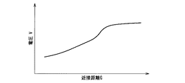
図7は、電導体と電磁石コイル16との距離である近接距離Gと電磁石コイル16の両端の電圧Vとの関係を示す説明図(グラフ)である。   FIG. 7 is an explanatory diagram (graph) showing the relationship between the proximity distance G, which is the distance between the conductor and the electromagnet coil 16, and the voltage V across the electromagnet coil 16.

電磁石コイル16に高周波定電流を流した場合の電磁石コイル16間の電圧は、電流供給開始時に逆起電力が発生するが、その後、十分な時間が経過する(定常状態になる)と、電磁石コイル16の導体抵抗による電圧降下分の直流電圧のみとなる。この直流電圧、すなわち、定常状態における電磁石コイル16間の電圧を検出すれば、電磁石コイル16の導体抵抗を求めることができる。電磁石コイル16を構成する配線13aの抵抗値と温度との関係を事前に調べておくことによって、求めた電磁石コイル16の導体抵抗から電磁石コイル16の周囲の温度を求めることができる。   When a high-frequency constant current is passed through the electromagnet coil 16, a counter electromotive force is generated at the start of current supply. However, after a sufficient time has elapsed (becomes a steady state), the electromagnet coil Only a DC voltage corresponding to a voltage drop due to 16 conductor resistances is obtained. By detecting this DC voltage, that is, the voltage between the electromagnet coils 16 in a steady state, the conductor resistance of the electromagnet coils 16 can be obtained. The temperature around the electromagnet coil 16 can be obtained from the obtained conductor resistance of the electromagnet coil 16 by examining the relationship between the resistance value and the temperature of the wiring 13a constituting the electromagnet coil 16 in advance.

また、近接距離とセンサ保持部12が保持するセンサを監視計測対象物となる配管2へ押し付ける圧力(押付け力)とは、所定の関係性を有するため、電磁石コイル16の周囲の温度における近接距離を求めれば、配管2への押付け力を求めることができる。   Further, the proximity distance and the pressure (pressing force) that presses the sensor held by the sensor holding unit 12 against the pipe 2 as the monitoring measurement object have a predetermined relationship, and therefore the proximity distance at the temperature around the electromagnetic coil 16. , The pressing force on the pipe 2 can be obtained.

次に、本発明の各実施形態に係るセンサ保持装置およびセンサ保持方法について、説明する。   Next, a sensor holding device and a sensor holding method according to each embodiment of the present invention will be described.

[第1の実施形態]
図8は、本発明の第1の実施形態に係るセンサ保持装置の一例である第1のセンサ保持装置10Aの構成を示した構成図である。
[First Embodiment]
FIG. 8 is a configuration diagram showing a configuration of a first sensor holding device 10A which is an example of the sensor holding device according to the first embodiment of the present invention.

第1のセンサ保持装置10Aは、センサ保持部12と、センサ保持部12の保持状態を監視(モニタリング)する監視部としての第1の保持状態モニタ回路21Aおよび電源回路22と、を具備する。   The first sensor holding device 10 </ b> A includes a sensor holding unit 12, and a first holding state monitoring circuit 21 </ b> A and a power supply circuit 22 as a monitoring unit that monitors (monitors) the holding state of the sensor holding unit 12.

第1の保持状態モニタ回路21Aは、保持状態モニタ回路21の一例であり、例えば、図8に示されるように、電磁石コイル16へ励磁電流(高周波信号)Ifを供給する高周波電源26と、電源回路22の直流定電流電源35から電磁石コイル16へ供給される励磁電流Icに励磁電流Ifを重畳させる結合器27と、所定の周波数よりも低い周波数を遮断し高周波電源26の高周波成分を通過させる第1のフィルタ28と、第1のフィルタ28から出力される信号の電圧値を計測する交流電圧測定器29と、高周波電源26の高周波成分を通過させずに直流成分のみを通過させる第2のフィルタ30と、第2のフィルタ30から出力される信号の電圧値を計測する直流電圧測定器31と、を備える。   The first holding state monitoring circuit 21A is an example of the holding state monitoring circuit 21. For example, as shown in FIG. 8, a high frequency power supply 26 that supplies an excitation current (high frequency signal) If to the electromagnet coil 16, and a power supply A coupler 27 that superimposes the excitation current If on the excitation current Ic supplied from the DC constant current power supply 35 of the circuit 22 to the electromagnet coil 16, and a frequency lower than a predetermined frequency is cut off and a high frequency component of the high frequency power supply 26 is allowed to pass. A first filter 28, an AC voltage measuring device 29 that measures the voltage value of the signal output from the first filter 28, and a second that passes only the DC component without passing the high-frequency component of the high-frequency power source 26. A filter 30 and a DC voltage measuring device 31 that measures a voltage value of a signal output from the second filter 30 are provided.

電源回路22は、電磁石コイル16に任意の励磁電流Icを供給するもので、電磁石コイル16の負荷(抵抗など)が変動しても一定電流を供給することのできる直流定電流電源35で構成される。   The power supply circuit 22 supplies an arbitrary exciting current Ic to the electromagnet coil 16, and is composed of a DC constant current power supply 35 that can supply a constant current even if the load (resistance, etc.) of the electromagnet coil 16 fluctuates. The

次に、第1のセンサ保持装置10Aにおけるセンサ保持方法、すなわち、監視計測対象物となる配管2への押付け力を算出方法および調整方法について説明する。   Next, a sensor holding method in the first sensor holding device 10 </ b> A, that is, a method for calculating and adjusting a pressing force to the pipe 2 that is a monitoring measurement object will be described.

図9は、図8に示される計測点P〜Pにおいて測定される波形を示した説明図であり、図9(A)、図9(B)、図9(C)および図9(D)は、それぞれ、計測点P,P,PおよびPで測定される波形を示した説明図である。 FIG. 9 is an explanatory diagram showing waveforms measured at the measurement points P A to P D shown in FIG. 8, and FIG. 9 (A), FIG. 9 (B), FIG. 9 (C) and FIG. D), respectively, the measurement point P a, P B, is an explanatory diagram showing a waveform measured by P C and P D.

図9(A)に示される波形は、電磁石コイル16に直流定電流電源35から励磁電流Icと高周波電源26からの励磁電流Ifが重畳させて印加している状態での電磁石コイル16に発生する電圧波形である。すなわち、図9(D)に示される電磁石コイル16に発生する電圧の直流成分(直流電圧波形)に、図9(C)に示される電磁石コイル16に発生する電圧の高周波(交流)成分(高周波電圧波形)が重畳した電圧波形である。   The waveform shown in FIG. 9A is generated in the electromagnet coil 16 in a state where the excitation current Ic from the DC constant current power supply 35 and the excitation current If from the high frequency power supply 26 are applied to the electromagnet coil 16 in a superimposed manner. It is a voltage waveform. That is, the DC component (DC voltage waveform) of the voltage generated in the electromagnet coil 16 shown in FIG. 9D is changed to the high frequency (AC) component (high frequency) of the voltage generated in the electromagnet coil 16 shown in FIG. The voltage waveform is a superimposed voltage waveform.

なお、直流定電流電源35から磁石コイル16に供給される励磁電流Icと高周波電源26からの励磁電流Ifを重畳させて印加している状態では、計測点Pにおける電圧波形は、図9(B)に示されるように、直流成分に交流成分(高周波成分)が重畳した波形となる。 In the state where the excitation current Ic supplied from the DC constant current power supply 35 to the magnet coil 16 and the excitation current If from the high frequency power supply 26 are applied in a superimposed manner, the voltage waveform at the measurement point P B is as shown in FIG. As shown in B), a waveform in which an AC component (high frequency component) is superimposed on a DC component is obtained.

第1のセンサ保持装置10Aのセンサ保持部12がセンサを監視計測対象物(配管2)へ押し付ける圧力(以下、単に「押付け力」と称する。)を算出するにあたっては、まず、準備として、電磁石コイル16の周囲の温度Tと電磁石コイル16の導体抵抗Rcとの関係(抵抗値特性)と、異なる周囲温度における近接距離Gと電磁石コイル16の両端の電圧(電磁石電圧)Vfsとの関係(近接距離特性)と、近接距離Gと監視計測対象物(配管2)への押付け力Fとの関係(押付け力特性)を事前に求めておく。   In calculating the pressure (hereinafter simply referred to as “pressing force”) by which the sensor holding unit 12 of the first sensor holding device 10A presses the sensor against the monitoring measurement object (pipe 2), first, as preparation, an electromagnet The relationship between the temperature T around the coil 16 and the conductor resistance Rc of the electromagnet coil 16 (resistance characteristic), and the relationship between the proximity distance G at different ambient temperatures and the voltage (electromagnet voltage) Vfs at both ends of the electromagnet coil 16 (proximity) The relationship (pressing force characteristic) between the distance characteristic) and the proximity distance G and the pressing force F to the monitoring measurement object (pipe 2) is obtained in advance.

図10〜図12は、それぞれ、事前に求める各種特性を説明する説明図(グラフ)であり、図10は電磁石コイル16の抵抗値特性を説明する説明図、図11は近接距離特性を説明する説明図、図12は押付け力特性を説明する説明図である。   10 to 12 are explanatory diagrams (graphs) for explaining various characteristics obtained in advance, FIG. 10 is an explanatory diagram for explaining the resistance value characteristics of the electromagnetic coil 16, and FIG. 11 is for explaining the proximity distance characteristics. FIG. 12 is an explanatory diagram for explaining the pressing force characteristics.

図10では、縦軸に電磁石コイル16の導通時の抵抗を示す導体抵抗Rcを、横軸に電磁石コイル16の周囲温度を示す温度Tをとって、導体抵抗Rcと温度Tとの関係が表されている。そして、導体抵抗Rcは、温度Tの一次関数(Rc=A1・T+B1)として近似される。ここで、係数A1は0以外の整数、係数B1は整数であり、一般にはA1およびB1は正の整数となる。   In FIG. 10, the vertical axis represents the conductor resistance Rc indicating the resistance when the electromagnet coil 16 is conductive, and the horizontal axis represents the temperature T indicating the ambient temperature of the electromagnet coil 16, and the relationship between the conductor resistance Rc and the temperature T is expressed. Has been. The conductor resistance Rc is approximated as a linear function of temperature T (Rc = A1 · T + B1). Here, the coefficient A1 is an integer other than 0, the coefficient B1 is an integer, and generally A1 and B1 are positive integers.

第1の保持状態モニタ回路21Aの直流電圧測定器31で測定される直流電圧Vdの測定値を得ることによって、電磁石コイル16の導体抵抗Rcを求めることができるので、電磁石コイル16の導体抵抗Rcの近似式(Rc=A1・T+B1)、すなわち、電磁石コイル16の抵抗値特性の情報があれば、電磁石コイル16の抵抗値特性と求めた導体抵抗Rcから当該導体抵抗Rcにおける温度Tを求めることができる。   The conductor resistance Rc of the electromagnetic coil 16 can be obtained by obtaining the measured value of the DC voltage Vd measured by the DC voltage measuring device 31 of the first holding state monitoring circuit 21A. If the information of the resistance value characteristic of the electromagnetic coil 16 is obtained, the temperature T at the conductor resistance Rc is obtained from the resistance value characteristic of the electromagnetic coil 16 and the obtained conductor resistance Rc. Can do.

図11(A)は温度Tにおける近接距離特性を示す説明図であり、縦軸に近接距離Gを、横軸に電磁石コイル16の電磁石電圧Vfsをとって、近接距離Gと電磁石電圧Vfsとの関係が表されている。ここで、近接距離Gは、温度Tの一次関数(G=Ac(T)・Vfs+Bc(T))として近似される。ここで、温度Tは、例えば、n(nは2以上の自然数)個の異なる温度T1,T2,…,Tnであり、係数Ac(T)および係数Bc(T)は、それぞれ、温度Tの関数である。   FIG. 11A is an explanatory diagram showing the proximity distance characteristic at the temperature T. The proximity distance G is taken on the vertical axis, and the electromagnet voltage Vfs of the electromagnet coil 16 is taken on the horizontal axis. The relationship is expressed. Here, the proximity distance G is approximated as a linear function of temperature T (G = Ac (T) · Vfs + Bc (T)). Here, the temperature T is, for example, n (n is a natural number of 2 or more) different temperatures T1, T2,..., Tn, and the coefficient Ac (T) and the coefficient Bc (T) are It is a function.

図11(B)は係数Acと温度Tとの関係を示す説明図であり、図11(C)は係数Bcと温度Tとの関係を示す説明図である。   FIG. 11B is an explanatory diagram showing the relationship between the coefficient Ac and the temperature T, and FIG. 11C is an explanatory diagram showing the relationship between the coefficient Bc and the temperature T.

図11(B)では、縦軸に係数Acを、横軸に温度Tをとって、係数Acと温度Tとの関係が表されている。図11(B)に示されるように、関数Ac(T)は右下がりの関係、すなわち、温度Tが上昇すると係数Acは減少する関係にある。また、図11(C)では、縦軸に係数Bcを、横軸に温度Tをとって、係数Bcと温度Tとの関係が表されている。図11(C)に示されるように、関数Bc(T)は右下がりの関係、すなわち、温度Tが上昇すると係数Bcは減少する関係にある。   In FIG. 11B, the coefficient Ac is plotted on the vertical axis and the temperature T is plotted on the horizontal axis, and the relationship between the coefficient Ac and the temperature T is represented. As shown in FIG. 11 (B), the function Ac (T) has a downward-sloping relationship, that is, the coefficient Ac decreases as the temperature T increases. In FIG. 11C, the relationship between the coefficient Bc and the temperature T is shown with the coefficient Bc on the vertical axis and the temperature T on the horizontal axis. As shown in FIG. 11C, the function Bc (T) is in a downward-sloping relationship, that is, the coefficient Bc decreases as the temperature T increases.

第1の保持状態モニタ回路21Aでは、交流電圧測定器29で測定される電磁石電圧Vfsの測定値を得ることができるので、近接距離特性の情報があれば、直流電圧測定器31で測定される直流電圧Vdと電磁石コイル16の抵抗値特性とから求められた温度における近接距離特性と、電磁石電圧Vfsの測定値とを用いて近接距離Gを求めることができる。   In the first holding state monitor circuit 21A, the measured value of the electromagnet voltage Vfs measured by the AC voltage measuring device 29 can be obtained. Therefore, if there is information on the proximity distance characteristic, the measured value is measured by the DC voltage measuring device 31. The proximity distance G can be obtained using the proximity distance characteristic at the temperature obtained from the DC voltage Vd and the resistance value characteristic of the electromagnet coil 16 and the measured value of the electromagnet voltage Vfs.

図12では、縦軸にセンサを監視計測対象物(配管2)への押し付ける押付け力Fを、横軸に近接距離Gをとって、押付け力Fと近接距離Gとの関係が表されている。そして、押付け力Fは、近接距離Gの一次関数(F=Ag・G+Bg)として近似される。ここで、係数Agは0以外の整数、係数Bgは整数であり、一般に、Agは負の整数、Bgは正の整数となる。   In FIG. 12, the relationship between the pressing force F and the proximity distance G is shown with the pressing force F pressing the sensor against the monitoring measurement object (pipe 2) on the vertical axis and the proximity distance G on the horizontal axis. . The pressing force F is approximated as a linear function (F = Ag · G + Bg) of the proximity distance G. Here, the coefficient Ag is an integer other than 0 and the coefficient Bg is an integer. In general, Ag is a negative integer and Bg is a positive integer.

第1の保持状態モニタ回路21Aでは、近接距離Gを求めることができるので、押付け力特性の情報があれば、求めた近接距離Gと押付け力特性とから求めた近接距離Gにおける押付け力を求めることができる。   Since the first holding state monitoring circuit 21A can determine the proximity distance G, if there is information on the pressing force characteristics, the pressing force at the proximity distance G determined from the determined proximity distance G and the pressing force characteristics is determined. be able to.

上述したように、電磁石コイル16の抵抗値特性、近接距離特性および押付け力特性を事前に求めておくことによって、電磁石コイル16の電磁石電圧Vfsおよび直流電圧Vdの測定値を得れば、電磁石コイル16の周囲の温度、所定温度における近接距離Gおよび当該近接距離Gの場合における押付け力を算出することができる。すなわち、電磁石コイル16の電磁石電圧Vfsおよび直流電圧Vdを測定することによって、押付け力を監視することができる。   As described above, if the measured values of the electromagnet voltage Vfs and the DC voltage Vd of the electromagnet coil 16 are obtained by obtaining the resistance value characteristic, proximity distance characteristic and pressing force characteristic of the electromagnet coil 16 in advance, the electromagnet coil It is possible to calculate the ambient temperature of 16, the proximity distance G at a predetermined temperature, and the pressing force in the case of the proximity distance G. That is, the pressing force can be monitored by measuring the electromagnet voltage Vfs and the DC voltage Vd of the electromagnet coil 16.

第1のセンサ保持装置10Aにおいて、センサ保持部12が保持するセンサを配管2へ押し付ける押付け力を算出するのに必要な情報は、事前に電磁石コイル16の抵抗値特性、近接距離特性および押付け力特性を求めておくこと、並びに、第1のセンサ保持装置10Aの操作者が以下のステップを行うことによって、得ることができる。   In the first sensor holding device 10A, information necessary to calculate the pressing force for pressing the sensor held by the sensor holding unit 12 against the pipe 2 includes the resistance value characteristic, the proximity distance characteristic, and the pressing force of the electromagnetic coil 16 in advance. It can be obtained by obtaining the characteristics and by the operator of the first sensor holding device 10A performing the following steps.

まず、操作者は、何らかのアクセス装置を用いて、配管2等の監視計測対象物に第1のセンサ保持装置10Aを接近させ、スイッチSWを閉じて(オンの状態に切り替え)、電源回路22から設定した直流電流(励磁電流Ic)を電磁石コイル16に供給させてセンサ保持部12を吸着させる。但し、人がアクセスできる環境下であれば上記アクセス装置に代わって人が配管2に第1のセンサ保持装置10Aを接近させても良い。その後、操作者は、直流電圧測定器31が指示する電圧値を読み、電磁石コイル16両端の直流電圧Vdを測定する。   First, the operator uses a certain access device to bring the first sensor holding device 10A close to the monitored object such as the pipe 2 and closes the switch SW (switches to the ON state). The set DC current (excitation current Ic) is supplied to the electromagnetic coil 16 to attract the sensor holding unit 12. However, in an environment where a person can access, the person may bring the first sensor holding device 10 </ b> A closer to the pipe 2 instead of the access device. Thereafter, the operator reads the voltage value indicated by the DC voltage measuring device 31 and measures the DC voltage Vd across the electromagnet coil 16.

続いて、高周波電源26を起動させて、スイッチSWを開いて(オフの状態に切り替えて)、電磁石コイル16へ直流電流を供給している線に高周波信号(励磁電流If)を重畳させた状態で、交流電圧測定器29が指示する電圧値を読む。すなわち、電磁石コイル16両端の交流電圧(電磁石電圧)Vfsを測定する。   Subsequently, the high frequency power supply 26 is activated, the switch SW is opened (switched to the OFF state), and the high frequency signal (excitation current If) is superimposed on the line supplying the direct current to the electromagnet coil 16. Then, the voltage value indicated by the AC voltage measuring device 29 is read. That is, the AC voltage (electromagnet voltage) Vfs across the electromagnet coil 16 is measured.

直流電圧Vdおよび電磁石電圧Vfsの測定を完了すれば、事前に求めた電磁石コイル16の抵抗値特性、近接距離特性と、押付け力特性と、測定して得られる電磁石コイル16の電磁石電圧Vfsおよび直流電圧Vdを用いて、電磁石コイル16の周囲の温度、電磁石コイル16の周囲の温度における近接距離Gおよび当該近接距離Gにおける押付け力を算出することができる。   When the measurement of the DC voltage Vd and the electromagnet voltage Vfs is completed, the resistance value characteristic, the proximity distance characteristic, the pressing force characteristic, and the electromagnet voltage Vfs and DC of the electromagnet coil 16 obtained by measurement are obtained. Using the voltage Vd, the temperature around the electromagnet coil 16, the proximity distance G at the temperature around the electromagnet coil 16, and the pressing force at the proximity distance G can be calculated.

また、センサ保持部12が保持するセンサを監視計測対象物としての配管2へ押し付ける圧力(押付け力)を算出することができれば、押し付け力の監視が可能となる。さらに、算出した押付け力が必要とする押付け力よりも大きいか小さいかに応じて、押付け力の増減、すなわち、押付け力の制御が可能となる。   Moreover, if the pressure (pressing force) which presses the sensor held by the sensor holding unit 12 against the pipe 2 as the monitoring measurement object can be calculated, the pressing force can be monitored. Furthermore, the pressing force can be increased or decreased, that is, the pressing force can be controlled depending on whether the calculated pressing force is larger or smaller than the required pressing force.

第1のセンサ保持装置10Aにおける押付け力の制御は、直流定電流電源35から電磁石コイル16へ供給する励磁電流Icを増減させることによってなされる。具体的には、現在の押付け力が必要とする押付け力よりも強く、配管2への押付け力を弱めたい場合、直流定電流電源35から電磁石コイル16へ供給する励磁電流Icを減少させる。一方、現在の押付け力が必要とする押付け力よりも弱く、配管2への押付け力を強めたい場合、直流定電流電源35から電磁石コイル16へ供給する励磁電流Icを増加させる。   The pressing force in the first sensor holding device 10A is controlled by increasing or decreasing the excitation current Ic supplied from the DC constant current power source 35 to the electromagnet coil 16. Specifically, when the current pressing force is stronger than the required pressing force and it is desired to weaken the pressing force to the pipe 2, the exciting current Ic supplied from the DC constant current power source 35 to the electromagnet coil 16 is decreased. On the other hand, when the current pressing force is weaker than the required pressing force and it is desired to increase the pressing force to the pipe 2, the exciting current Ic supplied from the DC constant current power source 35 to the electromagnet coil 16 is increased.

第1のセンサ保持装置10Aおよび第1のセンサ保持装置10Aで適用されるセンサ保持方法によれば、電磁石コイル16に発生する電圧の高周波(交流)成分である電磁石電圧Vfsおよび直流成分である直流電圧Vdを計測することができる。従って、計測によって得られた電磁石電圧Vfsおよび直流電圧Vdと、事前に求めておいた電磁石コイル16の抵抗値特性、近接距離特性および押付け力特性とを用いることで、ユーザは、センサ保持部12の監視計測対象物(配管2)への押付け力を求めることができる。   According to the first sensor holding device 10A and the sensor holding method applied to the first sensor holding device 10A, the electromagnet voltage Vfs which is a high frequency (alternating current) component of the voltage generated in the electromagnet coil 16 and the direct current which is a direct current component. The voltage Vd can be measured. Therefore, by using the electromagnet voltage Vfs and DC voltage Vd obtained by measurement and the resistance value characteristic, proximity distance characteristic, and pressing force characteristic of the electromagnet coil 16 obtained in advance, the user can use the sensor holding unit 12. The pressing force to the monitoring measurement object (pipe 2) can be obtained.

また、第1のセンサ保持装置10Aおよび第1のセンサ保持装置10Aで適用されるセンサ保持方法によれば、センサ保持部12の監視計測対象物への押付け力を求めることができるので、ユーザは、求めた押付け力の大小に応じて、直流定電流電源35から電磁石コイル16へ供給する励磁電流Icを増減させることができるので、容易に押付け力の強弱を制御することができる。   Further, according to the sensor holding method applied in the first sensor holding device 10A and the first sensor holding device 10A, the pressing force of the sensor holding unit 12 on the monitoring measurement object can be obtained, so that the user can Since the exciting current Ic supplied from the DC constant current power source 35 to the electromagnet coil 16 can be increased or decreased according to the obtained pressing force, the strength of the pressing force can be easily controlled.

さらに、監視計測対象物への押付け力の算出および押付け力の強弱制御は、遠隔で行うことができるので、監視計測対象物が存在する環境が、人が入れない雰囲気内で、環境(温度、放射線)が著しく変化する条件下であっても、適用することができる。   Furthermore, since the calculation of the pressing force on the monitoring measurement object and the strength control of the pressing force can be performed remotely, the environment where the monitoring measurement object exists can be controlled in the atmosphere (temperature, Even under conditions where the radiation) changes significantly, it can be applied.

さらにまた、従来のセンサ保持装置に対して、センサ保持部12側(図に示される隔離室1の室内)のケーブル数は増加しないので、マニピュレータ等のアクセス装置を用いて遠隔でセンサを取り付ける作業が発生したとしても、従来のセンサ保持装置と同等のアクセス性を維持することができる。   Furthermore, since the number of cables on the side of the sensor holding unit 12 (in the isolation chamber 1 shown in the figure) does not increase with respect to the conventional sensor holding device, the operation of attaching the sensor remotely using an access device such as a manipulator Even if this occurs, the accessibility equivalent to that of the conventional sensor holding device can be maintained.

[第2の実施形態]
図13は本発明の第2の実施形態に係るセンサ保持装置の一例である第2のセンサ保持装置10Bの構成を示した構成図である。
[Second Embodiment]
FIG. 13 is a configuration diagram showing a configuration of a second sensor holding device 10B which is an example of a sensor holding device according to the second embodiment of the present invention.

第2のセンサ保持装置10Bは、第1のセンサ保持装置10Aに対して、センサ保持部12が保持するセンサを監視計測対象物としての配管2へ押し付ける圧力(押付け力)を算出する押付け力算出処理部および押付け力算出処理部が算出した押付け力が指定した押付け力となるように制御する押付け力制御部としてのコントローラ45、デジタル信号をアナログ信号に変換するデジタル/アナログ変換器(以下、「D/A変換器」と称し、図においては「D/A」と示す。)46およびアナログ信号をデジタル信号に変換するアナログ/デジタル変換器(以下、「A/D変換器」と称し、図において「A/D」と示す。)47をさらに具備する点で相違するが、その他の点は実質的に相違しない。   The second sensor holding device 10B calculates a pressing force for calculating the pressure (pressing force) for pressing the sensor held by the sensor holding unit 12 against the pipe 2 as the monitoring measurement object with respect to the first sensor holding device 10A. The controller 45 as a pressing force control unit that controls the pressing force calculated by the processing unit and the pressing force calculation processing unit to be the specified pressing force, a digital / analog converter (hereinafter referred to as “analog signal”). "D / A converter" and indicated as "D / A" in the figure) 46 and an analog / digital converter (hereinafter referred to as "A / D converter") that converts an analog signal into a digital signal. It is different in that it further includes 47, but the other points are not substantially different.

そこで、本実施形態では、第1のセンサ保持装置10Aに対して実質的に相違する点を中心に説明し、第1のセンサ保持装置10Aと実質的に同一となる構成要素については同一の符号を付して、説明を省略する。   Therefore, in the present embodiment, the description will focus on the points that are substantially different from the first sensor holding device 10A, and the components that are substantially the same as those of the first sensor holding device 10A have the same reference numerals. The description is omitted.

第2のセンサ保持装置10Bは、第1のセンサ保持装置10Aに対して、押付け力を算出する押付け力算出処理部と、押付け力算出処理部が算出した押付け力が、指定した押付け力となるように制御する押付け力制御部とをさらに具備し、例えば、押付け力算出処理部および押付け力算出処理部としてのコントローラ45と、D/A変換器46およびA/D変換器47とをさらに具備する。ここで、D/A変換器46およびA/D変換器47は、コントローラ45と第1の保持状態モニタ回路21Aとのインターフェイスである。   In the second sensor holding device 10B, the pressing force calculation processing unit that calculates the pressing force and the pressing force calculated by the pressing force calculation processing unit become the specified pressing force with respect to the first sensor holding device 10A. And a controller 45 as a pressing force calculation processing unit and a pressing force calculation processing unit, and a D / A converter 46 and an A / D converter 47, for example. To do. Here, the D / A converter 46 and the A / D converter 47 are interfaces between the controller 45 and the first holding state monitor circuit 21A.

押付け力算出処理部としてのコントローラ45は、アナログ信号である測定交流電圧測定器29で測定される電磁石コイル16の電磁石電圧Vfsと直流電圧測定器31で測定される直流電圧Vdとを、A/D変換器47を介して、それぞれ、デジタル信号に変換して取り込む。コントローラ45は、事前に求めておいた電磁石コイル16の抵抗値特性、近接距離特性および押付け力特性の情報を有しており、取り込んだ電磁石電圧Vfs(デジタル信号)および直流電圧Vdのデジタル信号と、事前に求めておいた電磁石コイル16の抵抗値特性、近接距離特性および押付け力特性を用いて配管2への押付け力を算出する。   The controller 45 serving as the pressing force calculation processing unit calculates an A / A voltage between the electromagnet voltage Vfs of the electromagnet coil 16 measured by the measurement AC voltage measuring device 29 and the DC voltage Vd measured by the DC voltage measuring device 31 as analog signals. Each of them is converted into a digital signal and taken in via the D converter 47. The controller 45 has information on the resistance value characteristic, the proximity distance characteristic, and the pressing force characteristic of the electromagnet coil 16 that has been obtained in advance, and the acquired digital signal of the electromagnet voltage Vfs (digital signal) and the DC voltage Vd Then, the pressing force to the pipe 2 is calculated using the resistance value characteristic, proximity distance characteristic and pressing force characteristic of the electromagnet coil 16 obtained in advance.

また、押付け力制御部としてのコントローラ45は、センサ保持部12が保持するセンサを配管2へ押し付ける圧力(押付け力)が指定した押付け力となるように制御する制御指令(デジタル信号)をD/A変換器46でデジタル信号からアナログ信号へ変換して、電源回路22および第1の保持状態モニタ回路21Aへ与える。   Further, the controller 45 as a pressing force control unit outputs a control command (digital signal) for controlling the pressure (pressing force) pressing the sensor held by the sensor holding unit 12 against the pipe 2 to the specified pressing force. The A converter 46 converts the digital signal into an analog signal, and supplies it to the power supply circuit 22 and the first holding state monitor circuit 21A.

より詳細に説明すれば、コントローラ45は、電源回路22の直流定電流電源35へ出力電流指令を送信して励磁電流Icを制御する。また、コントローラ45は、第1の保持状態モニタ回路21Aの高周波電源26へ出力周波数指令と出力電圧指令を送信して励磁電流Ifを制御する。コントローラ45が励磁電流Icおよび励磁電流Ifを制御することによって、配管2への押付け力が制御される。   More specifically, the controller 45 transmits an output current command to the DC constant current power supply 35 of the power supply circuit 22 to control the excitation current Ic. Further, the controller 45 controls the excitation current If by transmitting an output frequency command and an output voltage command to the high frequency power supply 26 of the first holding state monitoring circuit 21A. The controller 45 controls the exciting current Ic and the exciting current If, whereby the pressing force to the pipe 2 is controlled.

次に、第2のセンサ保持装置10Bにおけるセンサ保持方法、すなわち、監視計測対象物となる配管2への押付け力を算出方法および調整方法について説明する。   Next, a sensor holding method in the second sensor holding device 10 </ b> B, that is, a method for calculating and adjusting a pressing force to the pipe 2 that is a monitoring measurement object will be described.

第2のセンサ保持装置10Bにおいて、センサ保持部12が保持するセンサを配管2へ押し付ける圧力(押付け力)を算出する押付け力算出手順および調整(制御)する調整(制御)手順は、例えば、以下に示すステップ(1)〜(8)に従って行われる。   In the second sensor holding device 10B, the pressing force calculation procedure for calculating the pressure (pressing force) for pressing the sensor held by the sensor holding unit 12 against the pipe 2 and the adjustment (control) procedure for adjusting (controlling) are as follows, for example: The steps (1) to (8) shown in FIG.

(1)配管2等の監視計測対象物に第2のセンサ保持装置10Bを接近させ、スイッチSWを閉じて(オンの状態に切り替え)、電源回路22から設定した直流電流(励磁電流Ic)を電磁石コイル16に供給し、センサ保持部12を配管2に吸着させる。監視計測対象物に第2のセンサ保持装置10Bを接近させる作業は何らかのアクセス装置を用いて行う。但し、人がアクセスできる環境下であれば上記アクセス装置の代わりに人が行っても良い。   (1) The second sensor holding device 10B is brought close to the monitoring measurement object such as the pipe 2 and the switch SW is closed (switched to the ON state), and the DC current (excitation current Ic) set from the power supply circuit 22 is applied. The electromagnet coil 16 is supplied, and the sensor holding part 12 is attracted to the pipe 2. The operation of bringing the second sensor holding device 10B closer to the monitoring measurement object is performed using some access device. However, in an environment where a person can access, a person may go instead of the access device.

(2)直流電圧測定器31で測定した電磁石コイル16両端の直流電圧Vdの測定データをインターフェイスとなるA/D変換器47を介してコントローラ45に取り込む。   (2) The measurement data of the DC voltage Vd across the electromagnet coil 16 measured by the DC voltage measuring device 31 is taken into the controller 45 via the A / D converter 47 serving as an interface.

(3)コントローラ45は、取り込んだ直流電圧測定器31で測定した直流電圧Vdの測定データから電磁石コイル16の導体抵抗Rcを算出し、算出した導体抵抗Rcと電磁石コイル16の周囲の温度Tとの関係を示す近似式(電磁石コイル16の抵抗値特性:Rc=A1・T+B1)の情報を用いて、電磁石コイル16の周囲の温度Tを算出する。   (3) The controller 45 calculates the conductor resistance Rc of the electromagnet coil 16 from the measurement data of the DC voltage Vd measured by the acquired DC voltage measuring device 31, and calculates the calculated conductor resistance Rc and the temperature T around the electromagnet coil 16. The temperature T around the electromagnet coil 16 is calculated using information of the approximate expression (resistance characteristic of the electromagnet coil 16: Rc = A1 · T + B1).

(4)高周波電源26を起動し、スイッチSWを開いて(オフの状態に切り替えて)、電磁石コイル16へ直流電流を供給している線に高周波信号(励磁電流If)を重畳させる。   (4) The high-frequency power supply 26 is activated, the switch SW is opened (switched to the OFF state), and a high-frequency signal (excitation current If) is superimposed on the line supplying the direct current to the electromagnet coil 16.

(5)交流電圧測定器29で測定した電磁石コイル16両端の交流電圧(電磁石電圧)Vfsの測定データをインターフェイスとなるA/D変換器47を介して、コントローラ45に取り込む。   (5) The measurement data of the AC voltage (electromagnet voltage) Vfs across the electromagnet coil 16 measured by the AC voltage measuring device 29 is taken into the controller 45 through the A / D converter 47 serving as an interface.

(6)コントローラ45は、事前に求めておいた近接距離特性と、取り込んだ交流電圧測定器29で測定した交流電圧(電磁石電圧)Vfsと、算出した導体抵抗Rcの周囲の温度Tとを用いて、温度Tにおける電磁石電圧Vfsと近接距離Gとの関係を示す近似式(近接距離特性)から近接距離Gを算出する。   (6) The controller 45 uses the proximity distance characteristics obtained in advance, the AC voltage (electromagnet voltage) Vfs measured by the acquired AC voltage measuring device 29, and the calculated temperature T around the conductor resistance Rc. Thus, the proximity distance G is calculated from an approximate expression (proximity distance characteristic) indicating the relationship between the electromagnet voltage Vfs at the temperature T and the proximity distance G.

(7)コントローラ45は、事前に求めておいた押付け力特性と、算出した近接距離Gとを用いて、近接距離Gの場合における押付け力Fを算出する。   (7) The controller 45 calculates the pressing force F in the case of the proximity distance G using the pressing force characteristics obtained in advance and the calculated proximity distance G.

(8)コントローラ45は、算出したセンサへの押付け力Fの値(算出値)と設定したセンサ押付け力の値(設定値)とを比較する。比較した結果、算出値が設定値より大きい場合には、D/A変換器46を介して電磁石コイル16に供給する電流値を減少させる指令を電源回路22の直流定電流電源35へ出力する。逆に、算出値が設定値より小さい場合には、電磁石コイル16に供給する電流値を増加させる指令を電源回路22の直流定電流電源35へ出力する。   (8) The controller 45 compares the calculated value of the pressing force F to the sensor (calculated value) with the set value of the sensor pressing force (set value). If the calculated value is larger than the set value as a result of the comparison, a command to decrease the current value supplied to the electromagnet coil 16 via the D / A converter 46 is output to the DC constant current power supply 35 of the power supply circuit 22. Conversely, if the calculated value is smaller than the set value, a command to increase the current value supplied to the electromagnet coil 16 is output to the DC constant current power supply 35 of the power supply circuit 22.

以降、上記ステップ(2),(3),(5),(6),(7),(8)の処理を連続的に繰り返すことによって、第2のセンサ保持装置10Bは、センサ保持部12を取り付けた監視計測対象物としての配管2の周囲温度が大きく変化したとしても、コントローラ45が、常時、押付け力を所定範囲内に維持することができる。   Thereafter, the second sensor holding device 10B is configured so that the sensor holding unit 12B is continuously repeated by repeating the processes of steps (2), (3), (5), (6), (7), and (8). Even if the ambient temperature of the pipe 2 as a monitoring and measuring object to which is attached changes greatly, the controller 45 can always maintain the pressing force within a predetermined range.

第2のセンサ保持装置10Bおよび第2のセンサ保持装置10Bで適用されるセンサ保持方法によれば、押付け力算出部としてのコントローラ45が、電磁石コイル16に発生する電圧の高周波(交流)成分である電磁石電圧Vfsおよび直流成分である直流電圧Vdを計測し、計測によって得られた電磁石電圧Vfsおよび直流電圧Vdと、事前に求めておいた電磁石コイル16の抵抗値特性、近接距離特性および押付け力特性とを用いてセンサ保持部12の監視計測対象物(配管2)への押付け力を求めることができるので、押付け力を監視することができる。   According to the sensor holding method applied in the second sensor holding device 10B and the second sensor holding device 10B, the controller 45 as the pressing force calculation unit uses a high frequency (alternating current) component of the voltage generated in the electromagnetic coil 16. A certain electromagnet voltage Vfs and a direct current voltage Vd which is a direct current component are measured, and the electromagnet voltage Vfs and direct current voltage Vd obtained by the measurement, and the resistance value characteristic, proximity distance characteristic and pressing force of the electromagnet coil 16 which are obtained in advance. Since the pressing force of the sensor holding unit 12 on the monitoring measurement object (pipe 2) can be obtained using the characteristics, the pressing force can be monitored.

また、第2のセンサ保持装置10Bおよび第2のセンサ保持装置10Bで適用されるセンサ保持方法によれば、押付け力制御部としてのコントローラ45が、求めた押付け力と設定される押付け力とを比較し、その結果に応じて、直流定電流電源35から電磁石コイル16へ供給する励磁電流Icを増減させることができるので、容易に押付け力の強弱を制御することができる。   Further, according to the sensor holding method applied in the second sensor holding device 10B and the second sensor holding device 10B, the controller 45 as the pressing force control unit obtains the calculated pressing force and the set pressing force. In comparison, the excitation current Ic supplied from the DC constant current power source 35 to the electromagnet coil 16 can be increased or decreased according to the result, so that the strength of the pressing force can be easily controlled.

なお、上述した本実施形態の説明において、第2のセンサ保持装置10Bは、一例としてコントローラ45と第1の保持状態モニタ回路21Aとの間にインターフェイスとなるD/A変換器46およびA/D変換器47を備えているが、当該インターフェイスをコントローラ45または第1の保持状態モニタ回路21Aが備える構成であっても良い。   In the description of the present embodiment described above, the second sensor holding device 10B includes, as an example, a D / A converter 46 and an A / D that serve as an interface between the controller 45 and the first holding state monitoring circuit 21A. Although the converter 47 is provided, the controller 45 or the first holding state monitor circuit 21A may be provided with the interface.

また、上述した本実施形態の説明において、コントローラ45が事前に求めておいた電磁石コイル16の抵抗値特性、近接距離特性および押付け力特性の情報を有していると説明したが、電磁石コイル16の抵抗値特性、近接距離特性および押付け力特性の情報は、コントローラ45が読み出し可能な記憶領域内に保持されていれば良く、必ずしも、コントローラ45が有している必要はない。   In the description of the present embodiment described above, it has been described that the controller 45 has information on the resistance value characteristic, the proximity distance characteristic, and the pressing force characteristic of the electromagnetic coil 16 obtained in advance. The information of the resistance value characteristic, the proximity distance characteristic, and the pressing force characteristic may be held in a storage area that can be read by the controller 45, and the controller 45 does not necessarily have to have the information.

さらに、第2のセンサ保持装置10Bは、押付け力算出処理部と押付け力制御部とを具備しているが、必ずしも、押付け力算出処理部および押付け力制御部の両処理部を具備する必要はない。例えば、第2のセンサ保持装置10Bの操作者が押付け力の算出結果を判断してから押付け力の制御を行う等、コンピュータにより押付け力の制御を行わないのであれば、押付け力制御部を具備しないセンサ保持装置を構成することもできる。   Further, the second sensor holding device 10B includes a pressing force calculation processing unit and a pressing force control unit. However, the second sensor holding device 10B does not necessarily include both the pressing force calculation processing unit and the pressing force control unit. Absent. For example, if the computer does not control the pressing force, such as controlling the pressing force after the operator of the second sensor holding device 10B determines the calculation result of the pressing force, a pressing force control unit is provided. It is also possible to configure a sensor holding device that does not.

[第3の実施形態]
図14は、本発明の第3の実施形態に係るセンサ保持装置の一例である第3のセンサ保持装置10Cの構成を示した構成図である。
[Third Embodiment]
FIG. 14 is a configuration diagram showing a configuration of a third sensor holding device 10C which is an example of a sensor holding device according to the third embodiment of the present invention.

第3のセンサ保持装置10Cは、第2のセンサ保持装置10Bに対して、第1の保持状態モニタ回路21Aの代わりに、第2の保持状態モニタ回路21Bを具備する点と、コントローラ45が有する情報の内容の点で相違するが、その他の点は実質的に相違しない。そこで、本実施形態では、第2のセンサ保持装置10Bに対して実質的に相違する点を中心に説明し、第2のセンサ保持装置10Bと実質的に同一となる構成要素については同一の符号を付して、説明を省略する。   The third sensor holding device 10C has a second holding state monitoring circuit 21B instead of the first holding state monitoring circuit 21A with respect to the second sensor holding device 10B, and the controller 45 has. It differs in the content of the information, but the other points are not substantially different. Therefore, in the present embodiment, the description will focus on the points that are substantially different from the second sensor holding device 10B, and the components that are substantially the same as those of the second sensor holding device 10B have the same reference numerals. The description is omitted.

第3のセンサ保持装置10Cは、第2のセンサ保持装置10Bに対して、第1の保持状態モニタ回路21Aの代わりに、第2の保持状態モニタ回路21Bを具備する。すなわち、第3のセンサ保持装置10Cは、第2のセンサ保持装置10Bと比較して、センサ保持部12の保持状態を監視(モニタリング)する監視部の構成が異なっている。   The third sensor holding device 10C includes a second holding state monitoring circuit 21B instead of the first holding state monitoring circuit 21A with respect to the second sensor holding device 10B. That is, the third sensor holding device 10C is different from the second sensor holding device 10B in the configuration of a monitoring unit that monitors (monitors) the holding state of the sensor holding unit 12.

第2の保持状態モニタ回路21Bは、第1の保持状態モニタ回路21Aに対して、第1の保持状態モニタ回路21Aが備える交流電圧測定器29の代わりに、高周波電源26から出力される電圧と電磁石コイル16の電磁石電圧との位相差を計測する位相差測定部としての位相差検出器49と、高周波電源26から出力される電圧を位相差検出器49に入力する際に通過させる第1のフィルタ(ハイパスフィルタ)28をさらに備える。   The second holding state monitor circuit 21B has a voltage output from the high frequency power supply 26 in place of the AC voltage measuring device 29 provided in the first holding state monitor circuit 21A with respect to the first holding state monitor circuit 21A. A phase difference detector 49 as a phase difference measuring unit that measures a phase difference from the electromagnet voltage of the electromagnet coil 16 and a first voltage that is passed when the voltage output from the high frequency power supply 26 is input to the phase difference detector 49. A filter (high-pass filter) 28 is further provided.

すなわち、第2の保持状態モニタ回路21Bを具備する第3のセンサ保持装置10Cでは、電磁石コイル16と監視計測対象物の一例である配管2との近接距離Gを求めるための情報として、高周波電源26から出力される電圧と電磁石コイル16の電磁石電圧との位相差を用いる。   That is, in the third sensor holding device 10C including the second holding state monitor circuit 21B, the high frequency power source is used as information for obtaining the proximity distance G between the electromagnet coil 16 and the pipe 2 which is an example of the monitoring measurement object. The phase difference between the voltage output from the electromagnetic wave 26 and the electromagnet voltage of the electromagnet coil 16 is used.

図15は位相差Pと近接距離Gとの関係(近接距離特性)を示す説明図であり、縦軸に近接距離Gを、横軸に高周波電源26から出力される電圧と電磁石コイル16の電磁石電圧との位相差をとって、近接距離Gと位相差Pとの関係が表されている。   FIG. 15 is an explanatory diagram showing the relationship (proximity distance characteristic) between the phase difference P and the proximity distance G. The vertical axis indicates the proximity distance G, the horizontal axis indicates the voltage output from the high-frequency power supply 26 and the electromagnet of the electromagnetic coil 16. The relationship between the proximity distance G and the phase difference P is expressed by taking the phase difference from the voltage.

位相差Pと近接距離Gとの関係は、図15に示されるように、相関があり、かつ、事前に求めることができるので、第3のセンサ保持装置10Cでは、第2のセンサ保持装置10Bで使用される電磁石電圧Vfsと近接距離Gとの関係(図11(A))の代わりに、位相差Pと近接距離Gとの関係(図15)を用いて近接距離Gが求められる。   As shown in FIG. 15, the relationship between the phase difference P and the proximity distance G has a correlation and can be obtained in advance. Therefore, in the third sensor holding device 10C, the second sensor holding device 10B. The proximity distance G is determined using the relationship between the phase difference P and the proximity distance G (FIG. 15) instead of the relationship between the electromagnet voltage Vfs and the proximity distance G used in FIG.

次に、第3のセンサ保持装置10Cにおけるセンサ保持方法、すなわち、監視計測対象物となる配管2への押付け力を算出方法および調整方法について説明する。   Next, a sensor holding method in the third sensor holding device 10 </ b> C, that is, a method for calculating and adjusting a pressing force to the pipe 2 as a monitoring measurement object will be described.

なお、第3のセンサ保持装置10Cにおけるセンサ保持方法は、第2のセンサ保持装置10Bにおけるセンサ保持方法に対して、監視計測対象物の一例である配管2との近接距離Gを求める際に、電磁石電圧を用いるか、位相差を用いるかの点で相違するが、その他の点では実質的に相違しない。すなわち、第2の実施形態で説明されるステップ(1)〜(8)のうち、ステップ(5),(6)については相違するが、その他のステップについては実質的に相違しない。そこで、以下の説明では、第2のセンサ保持装置10Bにおけるセンサ保持方法と相違するステップ(5),(6)について説明し、相違しない他のステップについては説明を省略する。   Note that the sensor holding method in the third sensor holding device 10C is similar to the sensor holding method in the second sensor holding device 10B in determining the proximity distance G to the pipe 2 that is an example of the monitoring measurement object. Although it differs in whether an electromagnet voltage is used or a phase difference is used, it is not substantially different in other points. That is, among steps (1) to (8) described in the second embodiment, steps (5) and (6) are different, but the other steps are not substantially different. Therefore, in the following description, steps (5) and (6) that are different from the sensor holding method in the second sensor holding device 10B will be described, and descriptions of other steps that are not different will be omitted.

第3のセンサ保持装置10Cにおける押付け力算出手順および調整(制御)手順のステップ(5)および(6)は、以下の通りである。   Steps (5) and (6) of the pressing force calculation procedure and the adjustment (control) procedure in the third sensor holding device 10C are as follows.

(5)位相差検出器49は、第1のフィルタ28を介して高周波電源26から出力する電圧と、第1のフィルタ28を介して電磁石コイル16両端の電圧とを取り込み、位相差時間値を計測する。コントローラ45は、位相差検出器49で計測した位相差の測定データ(位相差時間値)をインターフェイスとなるA/D変換器47を介して、コントローラ45に取り込む。   (5) The phase difference detector 49 takes in the voltage output from the high frequency power supply 26 via the first filter 28 and the voltage across the electromagnetic coil 16 via the first filter 28, and calculates the phase difference time value. measure. The controller 45 loads the phase difference measurement data (phase difference time value) measured by the phase difference detector 49 into the controller 45 via the A / D converter 47 serving as an interface.

(6)コントローラ45は、事前に求めておいた近接距離特性(位相差Pに対する近接距離Gの関係を示す近似式)の情報と、取り込んだ位相差Pの情報と、算出した導体抵抗Rcの周囲の温度Tとを用いて、温度Tにおける位相差Pと近接距離Gとの関係を示す近似式(近接距離特性)から近接距離Gを算出する。   (6) The controller 45 obtains information on the proximity distance characteristics (an approximate expression indicating the relationship of the proximity distance G with respect to the phase difference P) obtained in advance, information on the captured phase difference P, and the calculated conductor resistance Rc. Using the ambient temperature T, the proximity distance G is calculated from an approximate expression (proximity distance characteristic) indicating the relationship between the phase difference P at the temperature T and the proximity distance G.

第3のセンサ保持装置10Cおよび第3のセンサ保持装置10Cで適用されるセンサ保持方法によれば、第2のセンサ保持装置10Bおよび第2のセンサ保持装置10Bで適用されるセンサ保持方法で使用する情報とは異なる情報、すなわち、高周波電源26から出力する電圧と電磁石コイル16両端の電圧との位相差と、位相差Pと近接距離Gとの関係を示す情報とを用いて、第2のセンサ保持装置10Bおよび第2のセンサ保持装置10Bで適用されるセンサ保持方法と同様の効果を得ることができる。   According to the sensor holding method applied in the third sensor holding device 10C and the third sensor holding device 10C, used in the sensor holding method applied in the second sensor holding device 10B and the second sensor holding device 10B. Information different from the information to be transmitted, that is, the phase difference between the voltage output from the high-frequency power supply 26 and the voltage across the electromagnetic coil 16, and the information indicating the relationship between the phase difference P and the proximity distance G, The same effect as that of the sensor holding method applied in the sensor holding device 10B and the second sensor holding device 10B can be obtained.

なお、図14に示される第3のセンサ保持装置10Cは、第2のセンサ保持装置10Bが具備する第1の保持状態モニタ回路21Aの代わりに、第2の保持状態モニタ回路21Bを具備する構成としたが、第2のセンサ保持装置10Bではなく第1のセンサ保持装置10Aに対して適用しても良い。すなわち、第3のセンサ保持装置10Cを、第1のセンサ保持装置10Aが具備する第1の保持状態モニタ回路21Aの代わりに、第2の保持状態モニタ回路21Bを具備する構成としても良い。   Note that the third sensor holding device 10C shown in FIG. 14 includes a second holding state monitoring circuit 21B instead of the first holding state monitoring circuit 21A included in the second sensor holding device 10B. However, the present invention may be applied not to the second sensor holding device 10B but to the first sensor holding device 10A. That is, the third sensor holding device 10C may include the second holding state monitoring circuit 21B instead of the first holding state monitoring circuit 21A included in the first sensor holding device 10A.

[第4の実施形態]
図16は、本発明の第4の実施形態に係るセンサ保持装置の一例であるセンサ保持装置10Dの構成を示した構成図である。
[Fourth Embodiment]
FIG. 16 is a configuration diagram showing a configuration of a sensor holding device 10D which is an example of a sensor holding device according to the fourth embodiment of the present invention.

第4のセンサ保持装置10Dは、他(第1−3,5)のセンサ保持装置10A,10B,10C,10Eが具備するセンサ保持部12の代わりに、センサ保持部51を具備する点で相違するが、その他の点は実質的に相違しない。そこで、本実施形態では、他(第1−3,5)のセンサ保持装置10A,10B,10C,10Eに対して実質的に相違する点を中心に説明し、他(第1−3,5)のセンサ保持装置10A,10B,10C,10Eと実質的に同一となる構成要素については同一の符号を付して、説明を省略する。   The fourth sensor holding device 10D is different in that the sensor holding unit 51 is provided instead of the sensor holding unit 12 provided in the other (first, third, fifth) sensor holding devices 10A, 10B, 10C, and 10E. However, other points are not substantially different. Therefore, in the present embodiment, the description will focus on the points that are substantially different from the other (first, third, fifth) sensor holding devices 10A, 10B, 10C, 10E, and the other (first, third, fifth). ) Are substantially the same as the sensor holding devices 10A, 10B, 10C, and 10E, and the description thereof is omitted.

例えば、図16に示される第4のセンサ保持装置10Dは、第3のセンサ保持装置10Cが具備するセンサ保持部12の代わりに、センサ保持部51を具備する。センサ保持部51は、電磁石コイル16を適用して監視計測対象物としての配管2に吸着するセンサ保持部12に対して、さらに永久磁石52を備えており、電磁石と永久磁石52という異なる二種類の磁石によって、配管2に吸着することができる。   For example, the fourth sensor holding device 10D shown in FIG. 16 includes a sensor holding unit 51 instead of the sensor holding unit 12 included in the third sensor holding device 10C. The sensor holding unit 51 further includes a permanent magnet 52 with respect to the sensor holding unit 12 that is applied to the pipe 2 as the monitoring measurement object by applying the electromagnet coil 16, and two different types of electromagnet and permanent magnet 52 are provided. The magnet 2 can be adsorbed to the pipe 2.

次に、図16に示される第4のセンサ保持装置10Dを例にして、第4のセンサ保持装置10Dにおけるセンサ保持方法について説明する。   Next, a sensor holding method in the fourth sensor holding device 10D will be described by taking the fourth sensor holding device 10D shown in FIG. 16 as an example.

図16に示される第4のセンサ保持装置10Dにおけるセンサ保持方法では、第3のセンサ保持装置10Cにおけるセンサ保持方法に対して、センサ保持部51の吸着方法、すなわち、ステップ(1)が相違するが、他のステップについては実質的に相違しない。そこで、以下の説明では、第3のセンサ保持装置10Cにおけるセンサ保持方法と相違するステップ(1)について説明し、相違しない他のステップについては説明を省略する。   The sensor holding method in the fourth sensor holding device 10D shown in FIG. 16 differs from the sensor holding method in the third sensor holding device 10C in the suction method of the sensor holding unit 51, that is, step (1). However, the other steps are not substantially different. Therefore, in the following description, step (1) different from the sensor holding method in the third sensor holding device 10C will be described, and description of other steps that are not different will be omitted.

第4のセンサ保持装置10Dにおけるセンサ保持方法、すなわち、監視計測対象物となる配管2への押付け力を算出方法および調整方法では、ステップ(1)において、センサ保持部51を配管2等の監視計測対象物に吸着させる。センサ保持部51の配管2への吸着させる際には、コントローラ45が、まず、永久磁石52の吸引力に対して電磁石コイル16に供給する電流を逆方向に流し、センサ保持部51全体としての吸引力を減少させておき、その後、徐々にセンサ保持部51全体としての吸引力を増加させてセンサ保持部51を配管2に近接させる。   In the sensor holding method in the fourth sensor holding device 10D, that is, the method for calculating and adjusting the pressing force on the pipe 2 to be monitored and measured, in step (1), the sensor holding unit 51 is monitored for the pipe 2 and the like. Adsorb to the measurement object. When the sensor holding unit 51 is attracted to the pipe 2, the controller 45 first causes the current supplied to the electromagnet coil 16 to flow in the opposite direction with respect to the attractive force of the permanent magnet 52, and the sensor holding unit 51 as a whole. The suction force is reduced, and then the suction force of the sensor holding unit 51 as a whole is gradually increased to bring the sensor holding unit 51 closer to the pipe 2.

第4のセンサ保持装置10Dおよび第4のセンサ保持装置10Dで適用されるセンサ保持方法によれば、他のセンサ保持装置10A,10B,10C,10Eおよび他のセンサ保持装置10A,10B,10C,10Eで適用されるセンサ保持方法と同様に、押付け力の監視および所望の範囲内に保持するように制御することができる。   According to the sensor holding method applied in the fourth sensor holding device 10D and the fourth sensor holding device 10D, the other sensor holding devices 10A, 10B, 10C, 10E and the other sensor holding devices 10A, 10B, 10C, Similar to the sensor holding method applied in 10E, the pressing force can be monitored and controlled to be held within a desired range.

また、第4のセンサ保持装置10Dは、永久磁石52の他に電磁石としての電磁石コイル16を備えるセンサ保持部51を具備するので、永久磁石52のみを備える従来のセンサ保持装置では成し得ない吸着力の調整を、容易に、かつ、遠隔で行うことができる。すなわち、第4のセンサ保持装置10Dによれば、永久磁石52のみを備える従来のセンサ保持装置よりも、センサ保持部51を配管2等の監視計測対象物に着脱する作業が容易になる。   Further, the fourth sensor holding device 10D includes the sensor holding unit 51 including the electromagnet coil 16 as an electromagnet in addition to the permanent magnet 52, and thus cannot be achieved by a conventional sensor holding device including only the permanent magnet 52. The adsorption force can be adjusted easily and remotely. That is, according to the fourth sensor holding device 10 </ b> D, the work of attaching / detaching the sensor holding unit 51 to / from the monitoring measurement object such as the pipe 2 becomes easier than the conventional sensor holding device including only the permanent magnet 52.

さらに、第4のセンサ保持装置10Dが電磁石としての電磁石コイル16の他に永久磁石52を備えるセンサ保持部51を具備することで、電磁石コイル16に供給する励磁電流Icを、従来または他のセンサ保持装置10A,10B,10C,10Eよりも小さく抑えることができる。すなわち、第4のセンサ保持装置10Dでは、電磁石コイル16に励磁電流Icを供給する電源回路22および電磁石コイル16(より詳細には電磁石コイル16を構成する配線13a)の許容電流をより小さく抑えることができる。   Further, the fourth sensor holding device 10D includes the sensor holding unit 51 including the permanent magnet 52 in addition to the electromagnet coil 16 serving as an electromagnet, so that the excitation current Ic supplied to the electromagnet coil 16 can be changed from the conventional or other sensors. The holding devices 10A, 10B, 10C, and 10E can be kept smaller. That is, in the fourth sensor holding device 10D, the allowable current of the power supply circuit 22 that supplies the excitation current Ic to the electromagnet coil 16 and the electromagnet coil 16 (more specifically, the wiring 13a that constitutes the electromagnet coil 16) is suppressed to be smaller. Can do.

第4のセンサ保持装置10Dでは、従来または他のセンサ保持装置10A,10B,10C,10Eに比べ、電源回路22および電磁石コイル16の許容電流を小さくできるので、電源回路22を小型化でき、電磁石コイル16の配線13aを細線化でき、電磁石コイル16の発熱量を緩和することができる。   In the fourth sensor holding device 10D, the allowable current of the power supply circuit 22 and the electromagnet coil 16 can be reduced as compared with the conventional or other sensor holding devices 10A, 10B, 10C, and 10E. The wiring 13a of the coil 16 can be thinned, and the amount of heat generated by the electromagnet coil 16 can be reduced.

なお、第4のセンサ保持装置10Dは、図16に示される第4のセンサ保持装置10Dに限定されない。すなわち、センサ保持部12を具備するセンサ保持装置であれば良く、第3のセンサ保持装置10Cに限らず、上述した第1のセンサ保持装置10Aおよび第2のセンサ保持装置10B並びに後述する第5のセンサ保持装置10Eに適用できる。   The fourth sensor holding device 10D is not limited to the fourth sensor holding device 10D shown in FIG. That is, any sensor holding device including the sensor holding unit 12 may be used, and not only the third sensor holding device 10C, but also the first sensor holding device 10A and the second sensor holding device 10B described above and a fifth described later. It is applicable to the sensor holding device 10E.

[第5の実施形態]
図17は、本発明の第5の実施形態に係るセンサ保持装置の一例である第5のセンサ保持装置10Eの構成を示した構成図である。
[Fifth Embodiment]
FIG. 17 is a configuration diagram showing a configuration of a fifth sensor holding device 10E which is an example of a sensor holding device according to the fifth embodiment of the present invention.

第5のセンサ保持装置10Eは、第3のセンサ保持装置10Cに対して、第2の保持状態モニタ回路21Bの代わりに、第3の保持状態モニタ回路21Cを具備する点と、コントローラ45が有する情報の内容の点で相違するが、その他の点は実質的に相違しない。そこで、本実施形態では、第3のセンサ保持装置10Cに対して実質的に相違する点を中心に説明し、第3のセンサ保持装置10Cと実質的に同一となる構成要素については同一の符号を付して、説明を省略する。   The fifth sensor holding device 10E includes a third holding state monitor circuit 21C instead of the second holding state monitor circuit 21B, and the controller 45 has a third sensor holding device 10C. It differs in the content of the information, but the other points are not substantially different. Therefore, in the present embodiment, the description will focus on the points that are substantially different from the third sensor holding device 10C, and the components that are substantially the same as those of the third sensor holding device 10C are denoted by the same reference numerals. The description is omitted.

第5のセンサ保持装置10Eは、センサ保持部12と、センサ保持部12の保持状態を監視(モニタリング)する監視部としての第3の保持状態モニタ回路21Cおよび電源回路22と、を具備する。すなわち、第5のセンサ保持装置10Eは、第3のセンサ保持装置10Cと比較して、センサ保持部12の保持状態を監視(モニタリング)する監視部の構成が異なっている。   The fifth sensor holding device 10E includes a sensor holding unit 12, and a third holding state monitoring circuit 21C and a power supply circuit 22 as a monitoring unit that monitors (monitors) the holding state of the sensor holding unit 12. In other words, the fifth sensor holding device 10E is different from the third sensor holding device 10C in the configuration of a monitoring unit that monitors (monitors) the holding state of the sensor holding unit 12.

第3の保持状態モニタ回路21Cは、第2の保持状態モニタ回路21Bに対して、高周波電源26の周波数を変更する周波数可変機能と、位相差検出器49に入力する際に通過させる第1のフィルタ(ハイパスフィルタ)28の帯域を変更する通過帯域可変機能とを有する。   The third holding state monitor circuit 21 </ b> C has a frequency variable function for changing the frequency of the high frequency power supply 26 and the first holding state monitor circuit 21 </ b> B that is passed when input to the phase difference detector 49. And a passband variable function for changing the band of the filter (high-pass filter) 28.

第3の保持状態モニタ回路21Cを具備する第5のセンサ保持装置10Eでは、他の保持状態モニタ回路21A,21Bを具備する他のセンサ保持装置10A〜10Dのように、高周波電源26の周波数は固定ではなく、異なる複数の周波数に変化させることができるので、配管2等の監視計測対象物の周囲の構造(厚みや材質)および状態に変化が生じた場合であっても、異なる複数の周波数で高周波電源26の電源周波数を設定して測定を行えば、複数データの中から感度の良い周波数の信号を選んで抽出することができる。   In the fifth sensor holding device 10E having the third holding state monitoring circuit 21C, the frequency of the high frequency power supply 26 is the same as the other sensor holding devices 10A to 10D having the other holding state monitoring circuits 21A and 21B. Since it can be changed to a plurality of different frequencies instead of being fixed, a plurality of different frequencies can be used even when the structure (thickness or material) and state around the monitored object such as the pipe 2 are changed. If the measurement is performed with the power supply frequency of the high-frequency power supply 26 set, a signal having a high frequency sensitivity can be selected and extracted from a plurality of data.

第5のセンサ保持装置10Eにおけるコントローラ45は、他のセンサ保持装置10A〜10Dにおけるコントローラ45に対して、高周波電源26の周波数を可変する周波数変更指令を与えて高周波電源26の周波数を可変制御する周波数制御部と、第1のフィルタ28を通過する信号の周波数帯域を変更する帯域変更指令を与えて第1のフィルタ28を通過する信号の周波数帯域を可変制御する信号通過帯域制御部とをさらに備える。   The controller 45 in the fifth sensor holding device 10E gives a frequency change command for changing the frequency of the high-frequency power source 26 to the controllers 45 in the other sensor holding devices 10A to 10D to variably control the frequency of the high-frequency power source 26. A frequency control unit, and a signal passband control unit that variably controls the frequency band of the signal passing through the first filter 28 by giving a band change command for changing the frequency band of the signal passing through the first filter 28 Prepare.

周波数可変制御部および信号通過帯域可変制御部としてのコントローラ45は、第3の保持状態モニタ回路21Cに対して、高周波電源26の周波数を可変する周波数変更指令および第1のフィルタ28を通過する信号の周波数帯域を変更する帯域変更指令を与えることで、第3の保持状態モニタ回路21Cにおける高周波電源26の周波数および第1のフィルタ28の信号通過帯域を変更することができる。   The controller 45 serving as the frequency variable control unit and the signal passband variable control unit sends a frequency change command for changing the frequency of the high frequency power supply 26 and a signal passing through the first filter 28 to the third holding state monitor circuit 21C. By giving a band change command for changing the frequency band, the frequency of the high frequency power supply 26 and the signal pass band of the first filter 28 in the third holding state monitor circuit 21C can be changed.

図18は、高周波電源26の周波数f、位相差検出器49が検出する位相差Pおよび配管2等の監視計測対象物(電導体)と電磁石コイル16との距離である近接距離Gの関係を示す説明図である。より詳細には、図18(A)は周波数fを変化させた場合における位相差Pに対する近接距離Gの関係を示す説明図であり、図18(B)は近接距離Gを変化させた場合における周波数fに対する位相差Pの関係を示す説明図である。なお、図18は温度Tが一定の場合を示している。   FIG. 18 shows the relationship between the frequency f of the high-frequency power source 26, the phase difference P detected by the phase difference detector 49, and the proximity distance G, which is the distance between the monitoring measurement object (conductor) such as the pipe 2 and the electromagnetic coil 16. It is explanatory drawing shown. More specifically, FIG. 18A is an explanatory diagram showing the relationship of the proximity distance G to the phase difference P when the frequency f is changed, and FIG. 18B is a diagram when the proximity distance G is changed. It is explanatory drawing which shows the relationship of the phase difference P with respect to the frequency f. FIG. 18 shows a case where the temperature T is constant.

図18(A)に示される図(グラフ)と、図18(B)に示される図(グラフ)とは、同じ内容を異なる視点から示した内容であり、周波数f、位相差Pおよび近接距離Gが所定の関係にあることを示している。例えば、図18(A)に示されるように、近接距離Gは、位相差Pの一次関数(G=Ap(f)・P+Bp(f))として近似される。ここで、周波数fは、例えば、n(nは2以上の自然数)個の異なる周波数f1,f2,…,fnであり、係数Ap(f)および係数Bp(f)は、それぞれ、周波数fの関数である。   The diagram (graph) shown in FIG. 18A and the diagram (graph) shown in FIG. 18B show the same content from different viewpoints, and the frequency f, phase difference P, and proximity distance. G indicates that there is a predetermined relationship. For example, as shown in FIG. 18A, the proximity distance G is approximated as a linear function of the phase difference P (G = Ap (f) · P + Bp (f)). Here, the frequency f is, for example, n (n is a natural number of 2 or more) different frequencies f1, f2,..., Fn, and the coefficient Ap (f) and the coefficient Bp (f) It is a function.

位相差Pと近接距離Gとの関係は、事前に、ある周波数(例えばf1)において位相差Pを順次変化させた場合の近接距離Gを測定し、続いて周波数を順次変更し(例えばf2,…,fn)、同様の測定を行うことで求めることができる。一方、周波数fと位相差Pとの関係は、事前に、ある近接距離(例えばG1)において周波数fを順次変化させた場合の位相差Pを測定し、続いて近接距離を順次変更し(例えばG2,…,Gn)、同様の測定を行うことで求めることができる。   The relationship between the phase difference P and the proximity distance G is determined in advance by measuring the proximity distance G when the phase difference P is sequentially changed at a certain frequency (for example, f1), and then sequentially changing the frequency (for example, f2, .., Fn) can be obtained by performing the same measurement. On the other hand, the relationship between the frequency f and the phase difference P is determined in advance by measuring the phase difference P when the frequency f is sequentially changed at a certain proximity distance (for example, G1), and then sequentially changing the proximity distance (for example, G2,..., Gn) can be obtained by performing the same measurement.

次に、第5のセンサ保持装置10Eにおけるセンサ保持方法について説明する。   Next, a sensor holding method in the fifth sensor holding device 10E will be described.

第5のセンサ保持装置10Eにおけるセンサ保持方法では、第3のセンサ保持装置10Cにおけるセンサ保持方法に対して、コントローラ45が信号の取り込みを行う際に、高周波電源26の周波数を変更する点と、変更した高周波電源26の周波数に応じて第1のフィルタ28を通過させる周波数帯域を変更する点で相違するが、他のステップについては実質的に相違しない。すなわち、上述したステップ(1)〜(8)のうち、ステップ(6)については相違するが、その他のステップについては、実質的に相違しない。そこで、以下の説明では、第3のセンサ保持装置10Cにおけるセンサ保持方法と相違するステップについて説明し、相違しない他のステップについては説明を省略する。   In the sensor holding method in the fifth sensor holding device 10E, the controller 45 changes the frequency of the high-frequency power source 26 when the controller 45 captures a signal as compared with the sensor holding method in the third sensor holding device 10C. The difference is that the frequency band through which the first filter 28 passes is changed according to the changed frequency of the high-frequency power supply 26, but the other steps are not substantially different. That is, among steps (1) to (8) described above, step (6) is different, but the other steps are not substantially different. Therefore, in the following description, steps that are different from the sensor holding method in the third sensor holding device 10C will be described, and descriptions of other steps that are not different will be omitted.

第5のセンサ保持装置10Eにおける押付け力算出手順および調整(制御)手順のステップ(6)は、以下の通りである。   Step (6) of the pressing force calculation procedure and the adjustment (control) procedure in the fifth sensor holding device 10E is as follows.

(6)コントローラ45は、事前に求めておいた位相差Pと近接距離Gとの関係または周波数fと位相差Pとの関係の情報と、取り込んだ位相差Pの情報と、コントローラ45が現在制御している高周波電源26の周波数fの情報とを用いて、近接距離Gを算出する。   (6) The controller 45 obtains the information on the relationship between the phase difference P and the proximity distance G or the relationship between the frequency f and the phase difference P that has been obtained in advance, the information on the captured phase difference P, and the controller 45 The proximity distance G is calculated using information on the frequency f of the high-frequency power source 26 being controlled.

例えば、取り込んだ位相差Pの値がP1であり、高周波電源26の周波数fの値がf1であった場合、コントローラ45が位相差Pと近接距離Gとの関係を示す情報を近接距離Gの算出に用いる場合には、周波数f1の場合における位相差Pと近接距離Gとの関係を示す情報を用いて、位相差P1となる近接距離Gを求めることができる。一方、周波数fと位相差Pとの関係の情報を近接距離Gの算出に用いる場合には、近接距離G1,G2,…,Gnにおける周波数fと位相差Pとの関係を示す情報から、周波数f1の場合に位相差がP1となる近接距離Gは近接距離G1,G2,…,Gnのうち、何れであるかを求めることができる。   For example, if the captured phase difference P value is P1 and the frequency f value of the high frequency power supply 26 is f1, the controller 45 provides information indicating the relationship between the phase difference P and the proximity distance G to the proximity distance G. When used for the calculation, the proximity distance G that becomes the phase difference P1 can be obtained using information indicating the relationship between the phase difference P and the proximity distance G in the case of the frequency f1. On the other hand, when the information on the relationship between the frequency f and the phase difference P is used to calculate the proximity distance G, the information indicating the relationship between the frequency f and the phase difference P at the proximity distances G1, G2,. It is possible to determine which of the proximity distances G1, G2,..., Gn is the proximity distance G at which the phase difference is P1 in the case of f1.

なお、高周波電源26の周波数fを変化させた場合には、変化させた後の周波数で、ステップ(5)〜(8)の処理を行う。   In addition, when the frequency f of the high frequency power supply 26 is changed, the processes of steps (5) to (8) are performed at the changed frequency.

第5のセンサ保持装置10Eおよび第5のセンサ保持装置10Eで適用されるセンサ保持方法によれば、第3のセンサ保持装置10Cおよび第3のセンサ保持装置10Cで適用されるセンサ保持方法と同様に、第2のセンサ保持装置10Bおよび第2のセンサ保持装置10Bで適用されるセンサ保持方法と同様の効果を得ることができるのに加え、高周波電源26の周波数fを変化させて押付け力を求めることができるので、監視計測対象物の周囲の構造(厚みや材質)および周囲状態の変化が生じた場合でも、異なる周波数fのうち、感度の良い周波数の信号のみを選択して抽出することができる。   According to the sensor holding method applied in the fifth sensor holding device 10E and the fifth sensor holding device 10E, the same as the sensor holding method applied in the third sensor holding device 10C and the third sensor holding device 10C. In addition to the effects similar to those of the second sensor holding device 10B and the sensor holding method applied to the second sensor holding device 10B, the pressing force can be increased by changing the frequency f of the high frequency power source 26. Since it can be obtained, even when the surrounding structure (thickness or material) of the monitoring measurement object and the surrounding state change, only a signal having a sensitive frequency among the different frequencies f can be selected and extracted. Can do.

なお、図17に示される第5のセンサ保持装置10Eは、第3のセンサ保持装置10Cが具備する第2の保持状態モニタ回路21Bの代わりに、第3の保持状態モニタ回路21Cを具備する構成としたが、第1の保持状態モニタ回路21Aの代わりに、第3の保持状態モニタ回路21Cを具備する構成としても良い。すなわち、第1の保持状態モニタ回路21A対して、高周波電源26の周波数を変更する周波数可変機能と、位相差検出器49に入力する際に通過させる第1のフィルタ(ハイパスフィルタ)28の帯域を変更する通過帯域可変機能とをさらに有する第3の保持状態モニタ回路21Cを構成しても良い。   Note that the fifth sensor holding device 10E shown in FIG. 17 includes a third holding state monitor circuit 21C instead of the second holding state monitor circuit 21B included in the third sensor holding device 10C. However, instead of the first holding state monitoring circuit 21A, a third holding state monitoring circuit 21C may be provided. That is, for the first holding state monitor circuit 21A, the frequency variable function for changing the frequency of the high frequency power supply 26 and the band of the first filter (high-pass filter) 28 that is passed when input to the phase difference detector 49 are provided. You may comprise the 3rd holding | maintenance state monitor circuit 21C which further has the pass-band variable function to change.

以上、センサ保持装置10(10A〜10E)およびセンサ保持装置10で適用されるセンサ保持方法によれば、センサ保持部12,51の監視計測対象物(配管2)への押付け力を求めることができ、求めた押付け力の大小に応じて、直流定電流電源35から電磁石コイル16へ供給する励磁電流Icを増減させることができるので、押付け力の強弱を容易に制御することができる。   As described above, according to the sensor holding device 10 (10A to 10E) and the sensor holding method applied in the sensor holding device 10, the pressing force of the sensor holding units 12 and 51 on the monitoring measurement object (pipe 2) can be obtained. The exciting current Ic supplied from the DC constant current power source 35 to the electromagnet coil 16 can be increased or decreased according to the obtained pressing force, so that the strength of the pressing force can be easily controlled.

また、センサ保持部12,51の監視計測対象物への押付け力の算出および押付け力の強弱制御は、遠隔で行うことができるので、監視計測対象物が存在する環境が、人が入れない雰囲気内で、環境(温度、放射線)が著しく変化する条件下であっても、適用することができる。   In addition, since the calculation of the pressing force of the sensor holding units 12 and 51 on the monitoring measurement object and the control of the strength of the pressing force can be performed remotely, the environment in which the monitoring measurement object exists is an atmosphere in which no human can enter. In particular, the present invention can be applied even under conditions where the environment (temperature, radiation) changes significantly.

さらに、従来のセンサ保持装置に対して、センサ保持部12、51側(図に示される隔離室1の室内)のケーブル数は増加しないので、アクセス装置(マニピュレータ等)を用いて遠隔でセンサを取り付ける作業が発生したとしても、従来のセンサ保持装置と同等のアクセス性を維持することができる。   Furthermore, since the number of cables on the sensor holding portions 12 and 51 side (in the room of the isolation chamber 1 shown in the figure) does not increase with respect to the conventional sensor holding device, the sensor can be remotely connected using an access device (manipulator or the like). Even if the attaching operation occurs, the same accessibility as that of the conventional sensor holding device can be maintained.

なお、本発明は上記実施形態そのままに限定されるものではなく、実施段階では、上述した実施例以外にも様々な形態で実施することが可能であり、発明の要旨を逸脱しない範囲で、種々の省略、追加、置き換え、変更を行うことができる。これら実施形態やその変形は、発明の範囲や要旨に含まれるとともに、特許請求の範囲に記載された発明とその均等の範囲に含まれる。   It should be noted that the present invention is not limited to the above-described embodiment as it is, and can be implemented in various forms other than the above-described examples in the implementation stage, and various modifications can be made without departing from the spirit of the invention. Can be omitted, added, replaced, or changed. These embodiments and modifications thereof are included in the scope and gist of the invention, and are included in the invention described in the claims and the equivalents thereof.

1 隔離室
2 配管(監視計測対象物)
3 壁
10(10A,10B,10C,10D,10E) センサ保持装置
11 センサ
12 センサ保持部
13(13a,13b) 配線
16 電磁石コイル
17 鉄心
18 センサ固定具
20 制御盤
21(21A,21B,21C) 保持状態モニタ回路
22 電源回路
23 センサ信号処理回路
26 高周波電源
27 結合器
28 第1のフィルタ
29 交流電圧測定器
30 第2のフィルタ
31 直流電圧測定器
32 ライン
35 直流定電流電源
36 高周波電源
38 基準波形
39 観測波形
45 コントローラ
46 デジタル/アナログ(D/A)変換器
47 アナログ/デジタル(A/D)変換器
49 位相差検出器
51 センサ保持部
52 永久磁石
100 従来のセンサ保持装置
101 センサ保持部
102 センサ
104 永久磁石
105 センサプローブ
107 センサ信号処理装置
108 電磁石
109 直流定電流電源
1 Isolation chamber 2 Piping (monitoring / measurement object)
3 Wall 10 (10A, 10B, 10C, 10D, 10E) Sensor holding device 11 Sensor 12 Sensor holding portion 13 (13a, 13b) Wiring 16 Electromagnetic coil 17 Iron core 18 Sensor fixture 20 Control panel 21 (21A, 21B, 21C) Holding state monitor circuit 22 Power supply circuit 23 Sensor signal processing circuit 26 High frequency power supply 27 Coupler 28 First filter 29 AC voltage measuring instrument 30 Second filter 31 DC voltage measuring instrument 32 Line 35 DC constant current power supply 36 High frequency power supply 38 Reference Waveform 39 Observation waveform 45 Controller 46 Digital / analog (D / A) converter 47 Analog / digital (A / D) converter 49 Phase difference detector 51 Sensor holding part 52 Permanent magnet 100 Conventional sensor holding apparatus 101 Sensor holding part 102 Sensor 104 Permanent magnet 105 Sensor probe 107 Sen Signal processing device 108 Electromagnet 109 DC constant current power supply

Claims (13)

監視または計測の対象物である監視計測対象物に接触させるセンサを保持し、励磁電流の供給を受けて磁力を発生させる電磁石コイルを備えるセンサ保持部と、
前記電磁石コイルへ直流電流を供給する直流電流供給部と、
前記電磁石コイルへ高周波電流を供給する高周波電流供給部と、
前記直流電流供給部から前記電磁石コイルへ供給される直流電流に、前記高周波電流供給部から供給する高周波電流を重畳する交流成分重畳部と、
前記電磁石コイルの両端の電圧信号の交流成分を抽出して交流電圧を計測する交流電圧測定部と、
前記電磁石コイルの両端の電圧信号の直流成分を抽出して直流電圧を計測する直流電圧測定部と、を具備することを特徴とするセンサ保持装置。
A sensor holding unit that includes an electromagnetic coil that holds a sensor that is in contact with a monitoring or measurement object that is a monitoring or measurement object, and that generates a magnetic force by receiving an excitation current;
A direct current supply unit for supplying a direct current to the electromagnet coil;
A high-frequency current supply unit for supplying a high-frequency current to the electromagnet coil;
An alternating current component superimposing unit that superimposes a high frequency current supplied from the high frequency current supply unit on a direct current supplied from the direct current supply unit to the electromagnet coil;
An AC voltage measurement unit that extracts an AC component of a voltage signal at both ends of the electromagnet coil and measures an AC voltage;
A sensor holding apparatus comprising: a DC voltage measuring unit that extracts a DC component of a voltage signal at both ends of the electromagnet coil and measures a DC voltage.
前記センサを前記監視計測対象物に押し付ける押付け力を算出するに先立って予め求められる情報であり、前記電磁石コイルの導体抵抗と前記電磁石コイルの周囲温度との関係を示す第1の情報、異なる複数の温度における前記電磁石コイルの両端の電圧を示す電磁石電圧と前記監視計測対象物との距離を示す近接距離との関係を示す第2の情報、前記近接距離と前記センサを前記監視計測対象物に押し付ける押付け力との関係を示す第3の情報と、前記直流電流供給部が前記電磁石コイルへ供給する直流電流値の情報と、前記直流電圧部が測定した直流電圧値の情報と、前記交流電圧測定部が測定した交流電圧値の情報と、を取得し、取得した前記第1の情報、第2の情報、第3の情報、前記直流電流値の情報と、前記交流電圧の情報および前記直流電圧値の情報に基づき、前記センサを前記監視計測対象物に押し付ける押付け力を算出する押付け力算出処理部をさらに具備することを特徴とする請求項1記載のセンサ保持装置。 First information indicating the relationship between the conductor resistance of the electromagnetic coil and the ambient temperature of the electromagnetic coil, which is information obtained in advance prior to calculating the pressing force for pressing the sensor against the monitoring measurement object, a plurality of different information Second information indicating a relationship between an electromagnet voltage indicating a voltage at both ends of the electromagnet coil at a temperature and a proximity distance indicating a distance between the monitoring measurement object, the proximity distance and the sensor as the monitoring measurement object Third information indicating a relationship with the pressing force to be pressed, information on a DC current value supplied to the electromagnet coil by the DC current supply unit, information on a DC voltage value measured by the DC voltage unit, and the AC voltage AC voltage value information measured by the measurement unit, and the acquired first information, second information, third information, DC current value information, AC voltage information, and Based on said information of the DC voltage value, the sensor holding device according to claim 1, wherein said sensor characterized by including the monitor measuring a pressing force calculating a pressing force pressing the object calculation processing unit further. 前記電磁石コイルへ供給する直流電流を増減させて、前記センサを前記監視計測対象物に押し付ける押付け力を制御する押付け力制御部をさらに具備することを特徴とする請求項1又は2記載のセンサ保持装置。 The sensor holding device according to claim 1, further comprising a pressing force control unit that controls a pressing force for pressing the sensor against the monitoring measurement object by increasing or decreasing a direct current supplied to the electromagnet coil. apparatus. 監視または計測の対象物である監視計測対象物に接触させるセンサを保持し、励磁電流の供給を受けて磁力を発生させる電磁石コイルを備えるセンサ保持部と、
前記電磁石コイルへ直流電流を供給する直流電流供給部と、
前記電磁石コイルへ高周波電流を供給する高周波電流供給部と、
前記直流電流供給部から前記電磁石コイルへ供給される直流電流に、前記高周波電流供給部から供給する高周波電流を重畳する交流成分重畳部と、
前記電磁石コイルの両端の電圧信号の交流成分と、前記高周波電流供給部の両端の電圧信号とを抽出して、抽出した前記電磁石コイルの両端の電圧信号の交流成分と前記高周波電流供給部の両端の電圧信号との位相差を計測する位相差測定部と、
前記電磁石コイルの両端の電圧信号の直流成分を抽出して直流電圧を計測する直流電圧測定部と、を具備することを特徴とするセンサ保持装置。
A sensor holding unit that includes an electromagnetic coil that holds a sensor that is in contact with a monitoring or measurement object that is a monitoring or measurement object, and that generates a magnetic force by receiving an excitation current;
A direct current supply unit for supplying a direct current to the electromagnet coil;
A high-frequency current supply unit for supplying a high-frequency current to the electromagnet coil;
An alternating current component superimposing unit that superimposes a high frequency current supplied from the high frequency current supply unit on a direct current supplied from the direct current supply unit to the electromagnet coil;
The AC component of the voltage signal at both ends of the electromagnet coil and the voltage signal at both ends of the high-frequency current supply unit are extracted, and the extracted AC component of the voltage signal at both ends of the electromagnet coil and both ends of the high-frequency current supply unit A phase difference measuring unit for measuring a phase difference with the voltage signal of
A sensor holding apparatus comprising: a DC voltage measuring unit that extracts a DC component of a voltage signal at both ends of the electromagnet coil and measures a DC voltage.
前記センサを前記監視計測対象物に押し付ける押付け力を算出するに先立って予め求められる情報であり、前記電磁石コイルの導体抵抗と前記電磁石コイルの周囲温度との関係を示す第1の情報、異なる複数の温度における前記電磁石コイルの両端の電圧信号の交流成分と前記高周波電流供給部の両端の電圧信号との位相差と前記監視計測対象物との距離を示す近接距離との関係を示す第2の情報、前記近接距離と前記センサを前記監視計測対象物に押し付ける押付け力との関係を示す第3の情報と、前記直流電流供給部が前記電磁石コイルへ供給する直流電流値の情報と、前記直流電圧部が測定した直流電圧値の情報と、前記交流電圧測定部が測定した交流電圧値の情報と、を取得し、取得した前記第1の情報、第2の情報、第3の情報、前記直流電流値の情報と、前記交流電圧の情報および前記直流電圧値の情報に基づき、前記センサを前記監視計測対象物に押し付ける押付け力を算出する押付け力算出処理部をさらに具備することを特徴とする請求項4記載のセンサ保持装置。 First information indicating the relationship between the conductor resistance of the electromagnetic coil and the ambient temperature of the electromagnetic coil, which is information obtained in advance prior to calculating the pressing force for pressing the sensor against the monitoring measurement object, a plurality of different information A second relationship between the phase difference between the AC component of the voltage signal at both ends of the electromagnet coil and the voltage signal at both ends of the high-frequency current supply unit and the proximity distance indicating the distance from the monitoring measurement object at the temperature of Information, third information indicating a relationship between the proximity distance and a pressing force pressing the sensor against the monitoring measurement object, information on a direct current value supplied to the electromagnet coil by the direct current supply unit, and the direct current The information of the DC voltage value measured by the voltage unit and the information of the AC voltage value measured by the AC voltage measurement unit are acquired, and the acquired first information, second information, third information, The apparatus further comprises a pressing force calculation processing unit that calculates a pressing force for pressing the sensor against the monitoring measurement object based on the DC current value information, the AC voltage information, and the DC voltage value information. The sensor holding device according to claim 4. 前記電磁石コイルへ供給する直流電流を増減させて、前記センサを前記監視計測対象物に押し付ける押付け力を制御する押付け力制御部をさらに具備することを特徴とする請求項4又は5記載のセンサ保持装置。 The sensor holding device according to claim 4, further comprising a pressing force control unit that controls a pressing force for pressing the sensor against the monitoring measurement object by increasing or decreasing a direct current supplied to the electromagnet coil. apparatus. 前記高周波電流供給部が供給する高周波電流の周波数を可変制御する周波数制御部と、
前記電磁石コイルの両端の電圧信号の交流成分のうち抽出する周波数帯域を可変制御する信号通過帯域制御部と、をさらに具備し、
前記押付け力算出処理部は、前記センサを前記監視計測対象物に押し付ける押付け力を算出するに先立って予め求められる情報であり、異なる複数の周波数における前記電磁石電圧と前記監視計測対象物との距離を示す近接距離との関係を示す第4の情報と、前記周波数制御部が可変制御する前記高周波電流の周波数の情報を取得し、取得した前記第4の情報と、前記高周波電流の周波数の情報とに基づき、前記高周波電流の周波数および前記交流電圧測定部が測定した前記電磁石電圧の交流電圧値における前記近接距離を算出することを特徴とする請求項1乃至6のいずれか1項に記載のセンサ保持装置。
A frequency control unit that variably controls the frequency of the high-frequency current supplied by the high-frequency current supply unit;
A signal pass band control unit that variably controls the frequency band to be extracted from the AC component of the voltage signal at both ends of the electromagnet coil,
The pressing force calculation processing unit is information obtained in advance prior to calculating the pressing force for pressing the sensor against the monitoring measurement object, and the distance between the electromagnet voltage at different frequencies and the monitoring measurement object The fourth information indicating the relationship with the proximity distance indicating the frequency, the information on the frequency of the high-frequency current variably controlled by the frequency control unit, the acquired fourth information, and the information on the frequency of the high-frequency current 7. The proximity distance in the AC voltage value of the electromagnet voltage measured by the frequency of the high-frequency current and the AC voltage measurement unit is calculated based on the above. Sensor holding device.
前記センサ保持部は、永久磁石をさらに備えることを特徴とする請求項1乃至7のいずれか1項に記載のセンサ保持装置。 The sensor holding device according to claim 1, wherein the sensor holding unit further includes a permanent magnet. 監視または計測の対象物である監視計測対象物に接触させるセンサを保持し、励磁電流の供給を受けて磁力を発生させる電磁石コイルを備える手段と、前記電磁石コイルへ前記励磁電流として直流電流を供給する手段および高周波電流を供給する手段と、前記電磁石コイルへ供給される直流電流に、前記高周波電流を供給する手段から供給する高周波電流を重畳する手段と、前記電磁石コイルの両端の電圧信号の交流成分および前記高周波電流を供給する手段の両端の電圧信号の少なくとも一方を用いて、前記センサを前記監視計測対象物に押し付ける押付け力と既知の関係にある前記監視計測対象物との距離を示す近接距離に対して既知の関係を示す物理量を求める手段と、前記電磁石コイルの両端の電圧信号の直流成分を抽出して直流電圧を計測する手段と、前記近接距離に対して既知の関係を示す物理量を求める手段が求めた物理量と前記既知の関係を用いて前記押付け力を算出する手段と、前記押付け力を算出する手段が算出した押付け力が予め設定される範囲内ない場合に当該範囲内に収まるように前記押付け力を制御する手段と、を具備するセンサ保持装置を適用したセンサ保持方法であり、
前記高周波電流を供給する手段が、前記電磁石コイルへ高周波電流を供給するステップと、
前記高周波電流を重畳する手段が、前記直流電流を供給する手段から前記電磁石コイルへ供給する直流電流に前記電磁石コイルへ高周波電流を供給するステップで前記電磁石コイルに供給される高周波電流を重畳するステップと、
前記近接距離に対して既知の関係を示す物理量を求める手段が、前記電磁石コイルの両端の電圧信号の交流成分および前記高周波電流を供給する手段の両端の電圧信号の少なくとも一方を用いて、前記センサを前記監視計測対象物に押し付ける押付け力と既知の関係にある前記監視計測対象物との距離を示す近接距離に対して既知の関係を示す物理量を求めるステップと、を備えることを特徴とするセンサ保持方法。
Means comprising an electromagnet coil that holds a sensor to be in contact with a monitoring / measuring object that is an object to be monitored or measured and generates a magnetic force upon receiving an excitation current, and supplies a DC current as the exciting current to the electromagnet coil Means for supplying a high-frequency current, means for superimposing a high-frequency current supplied from the means for supplying the high-frequency current on a direct current supplied to the electromagnet coil, and alternating current of voltage signals at both ends of the electromagnet coil Proximity indicating a distance from the monitoring measurement object having a known relationship with a pressing force for pressing the sensor against the monitoring measurement object using at least one of a component and a voltage signal at both ends of the means for supplying the high-frequency current Means for obtaining a physical quantity indicating a known relationship with respect to the distance, and extracting a DC component of a voltage signal at both ends of the electromagnetic coil, Means for calculating the pressing force using the physical quantity obtained by the means for obtaining a physical quantity indicating a known relationship with respect to the proximity distance and the known relation; and a means for calculating the pressing force. Means for controlling the pressing force so that the calculated pressing force falls within a preset range when the calculated pressing force is not within a preset range, and a sensor holding method using a sensor holding device comprising:
The means for supplying the high frequency current supplies the high frequency current to the electromagnet coil;
The means for superimposing the high-frequency current superimposes the high-frequency current supplied to the electromagnetic coil in the step of supplying the high-frequency current to the electromagnet coil from the direct current supplied from the means for supplying the direct current to the electromagnet coil. When,
The means for obtaining a physical quantity indicating a known relationship with respect to the proximity distance uses at least one of an AC component of a voltage signal at both ends of the electromagnetic coil and a voltage signal at both ends of the means for supplying the high-frequency current, and A physical quantity indicating a known relationship with respect to a proximity distance indicating a distance from the monitoring measurement object that is in a known relationship with a pressing force that presses the object to the monitoring measurement object. Retention method.
前記押付け力を算出する手段が、前記直流電圧を計測する手段が計測した前記電磁石コイルの両端の電圧信号の直流電圧値の情報と、前記直流電流を供給する手段から前記電磁石コイルへ供給する直流電流値の情報と、を用いて前記電磁石コイルの導体抵抗を算出するステップと、
前記押付け力を算出する手段が、前記電磁石コイルの導体抵抗を算出するステップで算出された前記電磁石コイルの導体抵抗の情報と、前記センサを前記監視計測対象物に押し付ける押付け力を算出するに先立って予め求められる情報であり、前記電磁石コイルの導体抵抗と前記電磁石コイルの周囲温度との関係を示す情報とを、用いて前記電磁石コイルの周囲温度を求めるステップと、をさらに備えることを特徴とする請求項9記載のセンサ保持方法。
The means for calculating the pressing force has the DC voltage value information of the voltage signal at both ends of the electromagnet coil measured by the means for measuring the DC voltage, and the DC supplied from the means for supplying the DC current to the electromagnet coil. Calculating a conductor resistance of the electromagnetic coil using current value information; and
Prior to calculating the pressing force for pressing the sensor against the monitoring / measuring object, the means for calculating the pressing force calculates information on the conductor resistance of the electromagnetic coil calculated in the step of calculating the conductor resistance of the electromagnetic coil. And obtaining the ambient temperature of the electromagnet coil using information indicating the relationship between the conductor resistance of the electromagnet coil and the ambient temperature of the electromagnet coil. The sensor holding method according to claim 9.
前記押付け力を制御する手段が、前記押付け力を算出するステップで算出された押付け力が予め設定される範囲内か否かを判定し、予め設定される範囲内になかった場合、当該範囲内に収まるように、前記電磁石コイルへ供給する直流電流を変化させて前記押付け力を変化させるステップをさらに備えることを特徴とする請求項9または10記載のセンサ保持方法。 The means for controlling the pressing force determines whether or not the pressing force calculated in the step of calculating the pressing force is within a preset range. If the pressing force is not within the preset range, The sensor holding method according to claim 9, further comprising a step of changing the pressing force by changing a direct current supplied to the electromagnet coil so as to be within a range. 近接距離に対して既知の関係を示す物理量を求めるステップは、前記近接距離に対して既知の関係を示す物理量が、前記電磁石コイルの両端の電圧信号の交流電圧である場合、前記電磁石コイルの両端の電圧信号の交流電圧値の情報と、既知である前記電磁石コイルの両端の電圧信号の交流電圧と前記近接距離との関係を示す情報とを用いて、前記押付け力と既知の関係にある前記近接距離を求めるステップであることを特徴とする請求項9乃至11のいずれか1項に記載のセンサ保持方法。 The step of obtaining a physical quantity indicating a known relationship with respect to the proximity distance is configured such that when the physical quantity indicating the known relationship with respect to the proximity distance is an AC voltage of a voltage signal at both ends of the electromagnetic coil, both ends of the electromagnetic coil Using the information on the AC voltage value of the voltage signal and the information indicating the relationship between the AC voltage of the voltage signal at both ends of the known electromagnetic coil and the proximity distance, the pressing force has a known relationship. The sensor holding method according to claim 9, wherein the sensor holding method is a step of obtaining a proximity distance. 近接距離に対して既知の関係を示す物理量を求めるステップは、前記近接距離に対して既知の関係を示す物理量が、前記電磁石コイルの両端の電圧信号の交流成分と前記高周波電流供給部の両端の電圧信号との位相差である場合、前記電磁石コイルの両端の電圧信号の交流成分と前記高周波電流供給部の両端の電圧信号との位相差の情報と、既知である前記電磁石コイルの両端の電圧信号の交流成分と前記高周波電流供給部の両端の電圧信号との位相差と前記近接距離との関係を示す情報とを用いて、前記押付け力と既知の関係にある前記近接距離を求めるステップであることを特徴とする請求項9乃至11のいずれか1項に記載のセンサ保持方法。 The step of obtaining a physical quantity indicating a known relationship with respect to the proximity distance includes the step of determining the physical quantity indicating the known relationship with respect to the proximity distance between an AC component of a voltage signal at both ends of the electromagnetic coil and both ends of the high-frequency current supply unit. In the case of a phase difference from the voltage signal, information on the phase difference between the AC component of the voltage signal at both ends of the electromagnetic coil and the voltage signal at both ends of the high-frequency current supply unit, and the known voltage at both ends of the electromagnetic coil Using the information indicating the relationship between the proximity distance and the phase difference between the AC component of the signal and the voltage signal at both ends of the high-frequency current supply unit, and determining the proximity distance having a known relationship with the pressing force. The sensor holding method according to claim 9, wherein there is a sensor holding method.
JP2011245917A 2011-11-09 2011-11-09 Sensor holding device and sensor holding method Pending JP2013102098A (en)

Priority Applications (1)

Application Number Priority Date Filing Date Title
JP2011245917A JP2013102098A (en) 2011-11-09 2011-11-09 Sensor holding device and sensor holding method

Applications Claiming Priority (1)

Application Number Priority Date Filing Date Title
JP2011245917A JP2013102098A (en) 2011-11-09 2011-11-09 Sensor holding device and sensor holding method

Publications (1)

Publication Number Publication Date
JP2013102098A true JP2013102098A (en) 2013-05-23

Family

ID=48622443

Family Applications (1)

Application Number Title Priority Date Filing Date
JP2011245917A Pending JP2013102098A (en) 2011-11-09 2011-11-09 Sensor holding device and sensor holding method

Country Status (1)

Country Link
JP (1) JP2013102098A (en)

Cited By (6)

* Cited by examiner, † Cited by third party
Publication number Priority date Publication date Assignee Title
WO2016181919A1 (en) * 2015-05-11 2016-11-17 株式会社荏原製作所 Electromagnet device, electromagnet control device, electromagnet control method, and electromagnet system
JP2016213075A (en) * 2015-05-11 2016-12-15 株式会社荏原製作所 Electromagnet device
JP2016225382A (en) * 2015-05-28 2016-12-28 株式会社荏原製作所 Electromagnet controller and electromagnet control method
JP2017084563A (en) * 2015-10-27 2017-05-18 株式会社荏原製作所 Electromagnet controller and electromagnet system
US11244812B2 (en) 2018-04-20 2022-02-08 Ebara Corporation Electromagnet control device and electromagnet system
US11346896B2 (en) 2019-08-26 2022-05-31 Ebara Corporation Electromagnet control device and electromagnet system

Cited By (10)

* Cited by examiner, † Cited by third party
Publication number Priority date Publication date Assignee Title
WO2016181919A1 (en) * 2015-05-11 2016-11-17 株式会社荏原製作所 Electromagnet device, electromagnet control device, electromagnet control method, and electromagnet system
JP2016213075A (en) * 2015-05-11 2016-12-15 株式会社荏原製作所 Electromagnet device
CN107615890A (en) * 2015-05-11 2018-01-19 株式会社荏原制作所 Electromagnet apparatus, electromagnet control device, electromagnet control method and electromagnet system
CN110213875A (en) * 2015-05-11 2019-09-06 株式会社荏原制作所 Electromagnet control device, electromagnet, electromagnet control method and electromagnet system
US11295935B2 (en) 2015-05-11 2022-04-05 Ebara Corporation Electromagnet device, electromagnet controller, electromagnet control method, and electromagnet system
JP2016225382A (en) * 2015-05-28 2016-12-28 株式会社荏原製作所 Electromagnet controller and electromagnet control method
JP2017084563A (en) * 2015-10-27 2017-05-18 株式会社荏原製作所 Electromagnet controller and electromagnet system
US11244812B2 (en) 2018-04-20 2022-02-08 Ebara Corporation Electromagnet control device and electromagnet system
US11346896B2 (en) 2019-08-26 2022-05-31 Ebara Corporation Electromagnet control device and electromagnet system
US11662397B2 (en) 2019-08-26 2023-05-30 Ebara Corporation Electromagnet control device and electromagnet system

Similar Documents

Publication Publication Date Title
JP2013102098A (en) Sensor holding device and sensor holding method
TWI535304B (en) Device and method for detecting force factor of loudspeaker
US8378967B2 (en) Wearable electrical apparatus
TWI432747B (en) Apparatus for diagnosing deterioration of insulation
TWI403752B (en) A device for measuring alternating current magnetic permeability and method of measuring the same
CN103782134B (en) Enter line amplitude estimation in differential transformer displacement sensor using Goerzel algorithm
JP5984522B2 (en) Measuring system
JP2014003731A (en) Drive unit of vibration type actuator and medical system using the same
EP2768112A3 (en) Apparatus and method for detecting foreign object in wireless power transmitting system
WO2008024142A3 (en) Industrial process device utilizing magnetic induction
MX364305B (en) Method and device for real time estimation of the applied pressure and of noisiness in a brake element, in particular a brake pad.
WO2011148169A3 (en) Magnetic vibratory screen clamping
EP2063281A3 (en) Magnetic detection coil and apparatus for magnetic field measurement
CN101915637B (en) A kind of sinusoidal gas micro pressure generator
EP3563937B1 (en) Haptic actuator controller
Xu et al. Stick-on piezoelectromagnetic AC current monitoring of circuit breaker panels
CN107941898B (en) A magneto-acoustic multiplexed wire rope defect and stress integrated detection device
JP2009002681A (en) Magnetic measuring device provided with permanent magnet which performs periodic motion and oscillating coil
CN205449699U (en) Thermoelectric coupling loading experiment device of magnetic force
TW201221920A (en) Generating a control signal based on propagated data
CN108419186B (en) electroacoustic transducer and voice coil vibration displacement control method
van der Weijde et al. Force sensing for compliant actuators using coil spring inductance
JP6182695B2 (en) Complex permeability measuring device and its measuring method and application.
CN109387665A (en) Speed detector and speed detection method
JP2011226840A (en) Method and device for measurement of magnetic characteristic