[go: up one dir, main page]

JP2013090265A - Image processing apparatus and image processing program - Google Patents

Image processing apparatus and image processing program Download PDF

Info

Publication number
JP2013090265A
JP2013090265A JP2011231551A JP2011231551A JP2013090265A JP 2013090265 A JP2013090265 A JP 2013090265A JP 2011231551 A JP2011231551 A JP 2011231551A JP 2011231551 A JP2011231551 A JP 2011231551A JP 2013090265 A JP2013090265 A JP 2013090265A
Authority
JP
Japan
Prior art keywords
parallax
image
image data
pixel
subject
Prior art date
Legal status (The legal status is an assumption and is not a legal conclusion. Google has not performed a legal analysis and makes no representation as to the accuracy of the status listed.)
Pending
Application number
JP2011231551A
Other languages
Japanese (ja)
Inventor
Kiyoshige Shibazaki
清茂 芝崎
Muneki Hamashima
宗樹 浜島
Susumu Mori
晋 森
Current Assignee (The listed assignees may be inaccurate. Google has not performed a legal analysis and makes no representation or warranty as to the accuracy of the list.)
Nikon Corp
Original Assignee
Nikon Corp
Priority date (The priority date is an assumption and is not a legal conclusion. Google has not performed a legal analysis and makes no representation as to the accuracy of the date listed.)
Filing date
Publication date
Application filed by Nikon Corp filed Critical Nikon Corp
Priority to JP2011231551A priority Critical patent/JP2013090265A/en
Publication of JP2013090265A publication Critical patent/JP2013090265A/en
Pending legal-status Critical Current

Links

Images

Landscapes

  • Processing Or Creating Images (AREA)
  • Testing, Inspecting, Measuring Of Stereoscopic Televisions And Televisions (AREA)

Abstract

PROBLEM TO BE SOLVED: To prevent a parallax amount between parallax images of a focused object, which should be zero, from not becoming zero due to the influence of the aberrations etc. of photographic lenses used for photographing.SOLUTION: An image processing apparatus comprises: an image data acquisition unit which acquires parallax image data from an imaging device provided with aperture masks corresponding to each of at least a part of photoelectric converters and outputting at least two pieces of parallax image data; focus information acquisition unit which acquires focus information at capturing time of the parallax image data; and a parallax amount correction unit which corrects a parallax amount between the same subjects in the parallax image data, on the basis of focus information.

Description

本発明は、画像処理装置および画像処理プログラムに関する。   The present invention relates to an image processing apparatus and an image processing program.

2つの撮影光学系を用いて、右目用の画像と左目用の画像とから成るステレオ画像を撮像するステレオ撮像装置が知られている。このようなステレオ撮像装置は、2つの撮像光学系を一定の間隔で配置することにより、同一の被写体を撮像して得られる2つの画像に視差を生じさせる。
[先行技術文献]
[特許文献]
[特許文献1] 特開平8−47001号公報
A stereo imaging device that captures a stereo image composed of a right-eye image and a left-eye image using two imaging optical systems is known. Such a stereo imaging device causes parallax to occur in two images obtained by imaging the same subject by arranging two imaging optical systems at regular intervals.
[Prior art documents]
[Patent Literature]
[Patent Document 1] JP-A-8-47001

ピントが合ったオブジェクトに対する視差画像間の視差量は零であるはずにも関わらず、撮影に用いられた撮影レンズの収差等の影響により、視差量が零にならない場合があった。   Although the amount of parallax between parallax images with respect to a focused object should be zero, the amount of parallax may not become zero due to the influence of the aberration of the photographing lens used for photographing.

本発明の第1の態様における画像処理装置は、少なくとも一部の光電変換素子のそれぞれに対応して開口マスクが設けられた少なくとも2つの視差画像データを出力する撮像素子から視差画像データを取得する画像データ取得部と、視差画像データの撮像時における合焦情報を取得する合焦情報取得部と、合焦情報に基づいて、視差画像データにおける同一被写体間の視差量を補正する視差量補正部とを備える。   The image processing apparatus according to the first aspect of the present invention acquires parallax image data from an image sensor that outputs at least two parallax image data provided with an aperture mask corresponding to each of at least some of the photoelectric conversion elements. An image data acquisition unit, a focus information acquisition unit that acquires focus information at the time of capturing parallax image data, and a parallax amount correction unit that corrects the parallax amount between the same subjects in the parallax image data based on the focus information With.

本発明の第2の態様における撮像装置は、上記の撮像素子と画像処理装置を含み、上記の撮像素子は、隣接するn個(nは3以上の整数)の光電変換素子のうち、少なくとも3つに対応して設けられたそれぞれの開口マスクの開口は、互いに異なる波長帯域を透過させる少なくとも2種類のカラーフィルタから構成されるカラーフィルターパターンの一パターン内に含まれると共に、入射光の断面領域内の互いに異なる部分領域からの光束をそれぞれ通過させるように位置づけられ、n個の光電変換素子を一組とする光電変換素子群が周期的に配列されており、開口マスクが設けられた光電変換素子の出力信号に基づいて視差画像データを出力する。   An imaging device according to a second aspect of the present invention includes the above-described imaging device and an image processing device, and the imaging device includes at least 3 of n (n is an integer of 3 or more) adjacent photoelectric conversion devices. The apertures of the respective aperture masks provided corresponding to the two are included in one pattern of a color filter pattern composed of at least two types of color filters that transmit different wavelength bands, and a cross-sectional area of incident light The photoelectric conversion device is positioned so as to pass light beams from different partial areas of the inside, and a photoelectric conversion element group including a set of n photoelectric conversion elements is periodically arranged, and is provided with an aperture mask. Parallax image data is output based on the output signal of the element.

本発明の第3の態様における画像処理プログラムは、少なくとも一部の光電変換素子のそれぞれに対応して開口マスクが設けられた少なくとも2つの視差画像データを出力する撮像素子から視差画像データを取得する画像データ取得ステップと、視差画像データの撮像時における合焦情報を取得する合焦情報取得ステップと、合焦情報に基づいて、視差画像データにおける同一被写体間の視差量を補正する視差量補正ステップとをコンピュータに実行させる。   The image processing program according to the third aspect of the present invention acquires parallax image data from an image sensor that outputs at least two parallax image data provided with an aperture mask corresponding to each of at least some of the photoelectric conversion elements. An image data acquisition step, a focus information acquisition step for acquiring focus information at the time of capturing parallax image data, and a parallax amount correction step for correcting the parallax amount between the same subjects in the parallax image data based on the focus information And let the computer run.

なお、上記の発明の概要は、本発明の必要な特徴の全てを列挙したものではない。また、これらの特徴群のサブコンビネーションもまた、発明となりうる。   It should be noted that the above summary of the invention does not enumerate all the necessary features of the present invention. In addition, a sub-combination of these feature groups can also be an invention.

本発明の実施形態に係るデジタルカメラの構成を説明する図である。It is a figure explaining the structure of the digital camera which concerns on embodiment of this invention. 本発明の実施形態に係る撮像素子の断面を表す概略図である。It is the schematic showing the cross section of the image pick-up element which concerns on embodiment of this invention. 撮像素子の一部を拡大した様子を表す概略図である。It is the schematic showing a mode that a part of imaging device was expanded. 視差画素と被写体の関係を説明する概念図である。It is a conceptual diagram explaining the relationship between a parallax pixel and a to-be-photographed object. 視差画像を生成する処理を説明する概念図である。It is a conceptual diagram explaining the process which produces | generates a parallax image. 繰り返しパターンの他の例を示す図である。It is a figure which shows the other example of a repeating pattern. 二次元的な繰り返しパターンの例を示す図である。It is a figure which shows the example of a two-dimensional repeating pattern. 開口部の他の形状を説明する図である。It is a figure explaining the other shape of an opening part. ベイヤー配列を説明する図である。It is a figure explaining a Bayer arrangement. ベイヤー配列に対する視差画素の割り振りについて、視差画素の種類が2つである場合のバリエーションを説明する図である。It is a figure explaining the variation in case there are two kinds of parallax pixels about allocation of parallax pixels to a Bayer arrangement. バリエーションの一例を示す図である。It is a figure which shows an example of a variation. 他のバリエーションの一例を示す図である。It is a figure which shows an example of another variation. 他のバリエーションの一例を示す図である。It is a figure which shows an example of another variation. 他のカラーフィルタ配列を説明する図である。It is a figure explaining other color filter arrangement | sequences. W画素と視差画素の配列の一例を示す図である。It is a figure which shows an example of the arrangement | sequence of W pixel and a parallax pixel. 視差画像と2D画像の生成過程を示す概念図である。It is a conceptual diagram which shows the production | generation process of a parallax image and 2D image. 光学ファインダから観察される被写体像および測距領域を示す図である。It is a figure which shows the to-be-photographed image observed from an optical finder, and a ranging area. デジタルカメラと各被写体との距離を示す概念図である。It is a conceptual diagram which shows the distance of a digital camera and each to-be-photographed object. 視差マップの生成処理を説明する説明図である。It is explanatory drawing explaining the production | generation process of a parallax map. 視差マップの補正処理を説明する説明図である。It is explanatory drawing explaining the correction process of a parallax map. 較正情報の例を説明する説明図である。It is explanatory drawing explaining the example of calibration information. 視差マップを参照して原色情報を移植する処理の概念を示す図である。It is a figure which shows the concept of the process which transplants primary color information with reference to a parallax map.

以下、発明の実施の形態を通じて本発明を説明するが、以下の実施形態は特許請求の範囲にかかる発明を限定するものではない。また、実施形態の中で説明されている特徴の組み合わせの全てが発明の解決手段に必須であるとは限らない。   Hereinafter, the present invention will be described through embodiments of the invention, but the following embodiments do not limit the invention according to the claims. In addition, not all the combinations of features described in the embodiments are essential for the solving means of the invention.

画像処理装置の一形態である撮像装置としての本実施形態に係るデジタルカメラは、1つのシーンについて複数の視点数の画像を一度の撮影により生成できるように構成されている。互いに視点の異なるそれぞれの画像を視差画像と呼ぶ。   The digital camera according to the present embodiment as an imaging apparatus that is one form of the image processing apparatus is configured to be able to generate images of a plurality of viewpoints for one scene by one shooting. Each image having a different viewpoint is called a parallax image.

図1は、本発明の実施形態に係るデジタルカメラ10の構成を説明する図である。デジタルカメラ10は、撮影光学系としての撮影レンズ20を備え、光軸21に沿って入射する被写体光束を撮像素子100へ導く。デジタルカメラ10は、撮像素子100、制御部201、A/D変換回路202、メモリ203、駆動部204、画像処理部205、メモリカードIF207、操作部208、表示部209、LCD駆動回路210およびAFセンサ211を備える。   FIG. 1 is a diagram illustrating the configuration of a digital camera 10 according to an embodiment of the present invention. The digital camera 10 includes a photographic lens 20 as a photographic optical system, and guides a subject light beam incident along the optical axis 21 to the image sensor 100. The digital camera 10 includes an image sensor 100, a control unit 201, an A / D conversion circuit 202, a memory 203, a drive unit 204, an image processing unit 205, a memory card IF 207, an operation unit 208, a display unit 209, an LCD drive circuit 210, and an AF. A sensor 211 is provided.

なお、図示するように、撮像素子100へ向かう光軸21に平行な方向をz軸プラス方向と定め、z軸と直交する平面において紙面手前へ向かう方向をx軸プラス方向、紙面上方向をy軸プラス方向と定める。以降のいくつかの図においては、図1の座標軸を基準として、それぞれの図の向きがわかるように座標軸を表示する。   As shown in the figure, the direction parallel to the optical axis 21 toward the image sensor 100 is defined as the z-axis plus direction, the direction toward the front of the drawing in the plane orthogonal to the z-axis is the x-axis plus direction, and the upward direction on the drawing is y. The axis is defined as the plus direction. In the following several figures, the coordinate axes are displayed so that the orientation of each figure can be understood with reference to the coordinate axes of FIG.

撮影レンズ20は、複数の光学レンズ群から構成され、シーンからの被写体光束をその焦点面近傍に結像させる。なお、図1では撮影レンズ20を説明の都合上、瞳近傍に配置された仮想的な1枚のレンズで代表して表している。撮像素子100は、撮影レンズ20の焦点面近傍に配置されている。撮像素子100は、二次元的に複数の光電変換素子が配列された、例えばCCD、CMOSセンサ等のイメージセンサである。撮像素子100は、駆動部204によりタイミング制御されて、受光面上に結像された被写体像を画像信号に変換してA/D変換回路202へ出力する。   The taking lens 20 is composed of a plurality of optical lens groups, and forms an image of a subject light flux from the scene in the vicinity of its focal plane. In FIG. 1, for convenience of explanation, the photographic lens 20 is represented by a single virtual lens arranged in the vicinity of the pupil. The image sensor 100 is disposed near the focal plane of the photographic lens 20. The image sensor 100 is an image sensor such as a CCD or CMOS sensor in which a plurality of photoelectric conversion elements are two-dimensionally arranged. The image sensor 100 is controlled in timing by the drive unit 204, converts the subject image formed on the light receiving surface into an image signal, and outputs the image signal to the A / D conversion circuit 202.

A/D変換回路202は、撮像素子100が出力する画像信号をデジタル画像信号に変換してメモリ203へ出力する。画像処理部205は、メモリ203をワークスペースとして種々の画像処理を施し、画像データを生成する。特に、画像処理部205は、撮像素子100が出力する信号から画像データ群を生成して取得するデータ取得部231、取得した画像データ群に含まれる視差画像データ間で視差量を演算する視差量演算部232、カラー画像データに変換する画像変換部233を有する。それぞれの処理の詳細については、後述する。   The A / D conversion circuit 202 converts the image signal output from the image sensor 100 into a digital image signal and outputs the digital image signal to the memory 203. The image processing unit 205 performs various image processing using the memory 203 as a work space, and generates image data. In particular, the image processing unit 205 generates a data data group from a signal output from the image sensor 100 and acquires the data acquisition unit 231. A parallax amount for calculating a parallax amount between the parallax image data included in the acquired image data group. A calculation unit 232 and an image conversion unit 233 for converting into color image data are included. Details of each processing will be described later.

画像処理部205は、他にも選択された画像フォーマットに従って画像データを調整するなどの画像処理一般の機能も担う。生成された画像データは、LCD駆動回路210により表示信号に変換され、表示部209に表示される。また、メモリカードIF207に装着されているメモリカード220に記録される。   The image processing unit 205 also has general image processing functions such as adjusting image data according to the selected image format. The generated image data is converted into a display signal by the LCD drive circuit 210 and displayed on the display unit 209. The data is recorded on the memory card 220 attached to the memory card IF 207.

AFセンサ211は、被写体空間に対して複数の測距点が設定された位相差センサであり、それぞれの測距点において被写体像のデフォーカス量を検出する。一連の撮影シーケンスは、操作部208がユーザの操作を受け付けて、制御部201へ操作信号を出力することにより開始される。撮影シーケンスに付随するAF,AE等の各種動作は、制御部201に制御されて実行される。例えば、制御部201は、AFセンサ211の検出信号を解析して、撮影レンズ20の一部を構成するフォーカスレンズを移動させる合焦制御を実行する。   The AF sensor 211 is a phase difference sensor in which a plurality of distance measuring points are set for the subject space, and detects the defocus amount of the subject image at each distance measuring point. A series of shooting sequences is started when the operation unit 208 receives a user operation and outputs an operation signal to the control unit 201. Various operations such as AF and AE accompanying the imaging sequence are executed under the control of the control unit 201. For example, the control unit 201 analyzes the detection signal of the AF sensor 211 and executes focus control for moving a focus lens that constitutes a part of the photographing lens 20.

制御部201は、合焦情報取得部234と視差量補正部235としての機能を有する。合焦情報取得部234は、生成された画像データ群に対応する合焦情報を、AFセンサ211等の出力から生成して取得する。また、視差量補正部235は、視差量演算部232によって演算された視差量を、合焦情報取得部234が取得した合焦情報を用いて補正する。それぞれの処理の詳細については、後述する。   The control unit 201 has functions as a focusing information acquisition unit 234 and a parallax amount correction unit 235. The focusing information acquisition unit 234 generates and acquires focusing information corresponding to the generated image data group from the output of the AF sensor 211 or the like. Further, the parallax amount correction unit 235 corrects the parallax amount calculated by the parallax amount calculation unit 232 using the focusing information acquired by the focusing information acquisition unit 234. Details of each processing will be described later.

ROM221は、不揮発性メモリであり、デジタルカメラ10を制御するプログラム、各種パラメータ等を記憶している。また、後述する較正情報を記憶する役割も担う。   The ROM 221 is a non-volatile memory, and stores a program for controlling the digital camera 10, various parameters, and the like. It also plays a role of storing calibration information, which will be described later.

次に、撮像素子100の構成について詳細に説明する。図2は、本発明の実施形態に係る撮像素子の断面を表す概略図である。図2(a)は、カラーフィルタ102と開口マスク103が別体で構成される撮像素子100の断面概略図である。また、図2(b)は、撮像素子100の変形例として、カラーフィルタ部122と開口マスク部123が一体的に構成されたスクリーンフィルタ121を備える撮像素子120の断面外略図である。   Next, the configuration of the image sensor 100 will be described in detail. FIG. 2 is a schematic diagram showing a cross section of the image sensor according to the embodiment of the present invention. FIG. 2A is a schematic cross-sectional view of the image sensor 100 in which the color filter 102 and the aperture mask 103 are separately formed. FIG. 2B is a schematic cross-sectional view of an image pickup device 120 including a screen filter 121 in which a color filter portion 122 and an opening mask portion 123 are integrally formed as a modification of the image pickup device 100.

図2(a)に示すように、撮像素子100は、被写体側から順に、マイクロレンズ101、カラーフィルタ102、開口マスク103、配線層105および光電変換素子108が配列されて構成されている。光電変換素子108は、入射する光を電気信号に変換するフォトダイオードにより構成される。光電変換素子108は、基板109の表面に二次元的に複数配列されている。   As shown in FIG. 2A, the image sensor 100 is configured by arranging a micro lens 101, a color filter 102, an aperture mask 103, a wiring layer 105, and a photoelectric conversion element 108 in this order from the subject side. The photoelectric conversion element 108 is configured by a photodiode that converts incident light into an electrical signal. A plurality of photoelectric conversion elements 108 are two-dimensionally arranged on the surface of the substrate 109.

光電変換素子108により変換された画像信号、光電変換素子108を制御する制御信号等は、配線層105に設けられた配線106を介して送受信される。また、各光電変換素子108に一対一に対応して設けられた開口部104を有する開口マスク103が、配線層に接して設けられている。開口部104は、後述するように、対応する光電変換素子108ごとにシフトさせて、相対的な位置が厳密に定められている。詳しくは後述するが、この開口部104を備える開口マスク103の作用により、光電変換素子108が受光する被写体光束に視差が生じる。   An image signal converted by the photoelectric conversion element 108, a control signal for controlling the photoelectric conversion element 108, and the like are transmitted and received through the wiring 106 provided in the wiring layer 105. In addition, an opening mask 103 having openings 104 provided in one-to-one correspondence with each photoelectric conversion element 108 is provided in contact with the wiring layer. As will be described later, the opening 104 is shifted for each corresponding photoelectric conversion element 108 so that the relative position is precisely determined. As will be described in detail later, parallax occurs in the subject light beam received by the photoelectric conversion element 108 by the action of the opening mask 103 including the opening 104.

一方、視差を生じさせない光電変換素子108上には、開口マスク103が存在しない。別言すれば、対応する光電変換素子108に対して入射する被写体光束を制限しない、つまり有効光束の全体を通過させる開口部104を有する開口マスク103が設けられているとも言える。視差を生じさせることはないが、実質的には配線106によって形成される開口107が入射する被写体光束を規定するので、配線106を、視差を生じさせない有効光束の全体を通過させる開口マスクと捉えることもできる。開口マスク103は、各光電変換素子108に対応して別個独立に配列しても良いし、カラーフィルタ102の製造プロセスと同様に複数の光電変換素子108に対して一括して形成しても良い。   On the other hand, the aperture mask 103 does not exist on the photoelectric conversion element 108 that does not generate parallax. In other words, it can be said that the aperture mask 103 having the aperture 104 that does not limit the subject luminous flux incident on the corresponding photoelectric conversion element 108, that is, allows the entire effective luminous flux to pass therethrough is provided. Although no parallax is generated, the aperture 107 formed by the wiring 106 defines the subject luminous flux that is incident, so the wiring 106 is regarded as an aperture mask that allows the entire effective luminous flux that does not cause parallax to pass. You can also. The opening mask 103 may be arranged separately and independently corresponding to each photoelectric conversion element 108, or may be formed collectively for a plurality of photoelectric conversion elements 108 in the same manner as the manufacturing process of the color filter 102. .

カラーフィルタ102は、開口マスク103上に設けられている。カラーフィルタ102は、各光電変換素子108に対して特定の波長帯域を透過させるように着色された、光電変換素子108のそれぞれに一対一に対応して設けられるフィルタである。カラー画像を出力するには、互いに異なる少なくとも3種類のカラーフィルタが配列されれば良い。これらのカラーフィルタは、カラー画像を生成するための原色フィルタと言える。原色フィルタの組み合わせは、例えば赤色波長帯を透過させる赤フィルタ、緑色波長帯を透過させる緑フィルタ、および青色波長帯を透過させる青フィルタである。これらのカラーフィルタは、後述するように、光電変換素子108に対応して格子状に配列される。   The color filter 102 is provided on the opening mask 103. The color filter 102 is a filter provided in a one-to-one correspondence with each photoelectric conversion element 108, which is colored so as to transmit a specific wavelength band to each photoelectric conversion element 108. In order to output a color image, it is only necessary to arrange at least three different color filters. These color filters can be said to be primary color filters for generating a color image. The primary color filter combination is, for example, a red filter that transmits the red wavelength band, a green filter that transmits the green wavelength band, and a blue filter that transmits the blue wavelength band. As will be described later, these color filters are arranged in a lattice pattern corresponding to the photoelectric conversion elements 108.

マイクロレンズ101は、カラーフィルタ102上に設けられている。マイクロレンズ101は、入射する被写体光束のより多くを光電変換素子108へ導くための集光レンズである。マイクロレンズ101は、光電変換素子108のそれぞれに一対一に対応して設けられている。マイクロレンズ101は、撮影レンズ20の瞳中心と光電変換素子108の相対的な位置関係を考慮して、より多くの被写体光束が光電変換素子108に導かれるようにその光軸がシフトされていることが好ましい。さらには、開口マスク103の開口部104の位置と共に、後述の特定の被写体光束がより多く入射するように配置位置が調整されても良い。   The microlens 101 is provided on the color filter 102. The microlens 101 is a condensing lens for guiding more incident subject light flux to the photoelectric conversion element 108. The microlenses 101 are provided in a one-to-one correspondence with the photoelectric conversion elements 108. In consideration of the relative positional relationship between the pupil center of the taking lens 20 and the photoelectric conversion element 108, the optical axis of the microlens 101 is shifted so that more subject light flux is guided to the photoelectric conversion element 108. It is preferable. Furthermore, the arrangement position may be adjusted so that more specific subject light beam, which will be described later, is incident along with the position of the opening 104 of the opening mask 103.

このように、各々の光電変換素子108に対応して一対一に設けられる開口マスク103、カラーフィルタ102およびマイクロレンズ101の一単位を画素と呼ぶ。特に、視差を生じさせる開口マスク103が設けられた画素を視差画素、視差を生じさせる開口マスク103が設けられていない画素を視差なし画素と呼ぶ。例えば、撮像素子100の有効画素領域が24mm×16mm程度の場合、画素数は1200万程度に及ぶ。   As described above, one unit of the aperture mask 103, the color filter 102, and the microlens 101 provided in one-to-one correspondence with each photoelectric conversion element 108 is referred to as a pixel. In particular, a pixel provided with the opening mask 103 that generates parallax is referred to as a parallax pixel, and a pixel that is not provided with the opening mask 103 that generates parallax is referred to as a non-parallax pixel. For example, when the effective pixel area of the image sensor 100 is about 24 mm × 16 mm, the number of pixels reaches about 12 million.

なお、集光効率、光電変換効率が良いイメージセンサの場合は、マイクロレンズ101を設けなくても良い。また、裏面照射型イメージセンサの場合は、配線層105が光電変換素子108とは反対側に設けられる。   Note that in the case of an image sensor with good light collection efficiency and photoelectric conversion efficiency, the microlens 101 may not be provided. In the case of a back-illuminated image sensor, the wiring layer 105 is provided on the side opposite to the photoelectric conversion element 108.

カラーフィルタ102と開口マスク103の組み合わせには、さまざまなバリエーションが存在する。図2(a)において、開口マスク103の開口部104に色成分を持たせれば、カラーフィルタ102と開口マスク103を一体的に形成することができる。また、特定の画素を被写体の輝度情報を取得する画素とする場合、その画素には、対応するカラーフィルタ102を設けなくても良い。あるいは、可視光のおよそ全ての波長帯域を透過させるように、着色を施さない透明フィルタを配列しても良い。   There are various variations in the combination of the color filter 102 and the aperture mask 103. In FIG. 2A, the color filter 102 and the opening mask 103 can be integrally formed if the opening 104 of the opening mask 103 has a color component. In addition, when a specific pixel is a pixel that acquires luminance information of a subject, the corresponding color filter 102 may not be provided for the pixel. Or you may arrange | position the transparent filter which does not give coloring so that the substantially all wavelength band of visible light may be permeate | transmitted.

輝度情報を取得する画素を視差画素とする場合、つまり、視差画像を少なくとも一旦はモノクロ画像として出力するのであれば、図2(b)として示す撮像素子120の構成を採用し得る。すなわち、カラーフィルタとして機能するカラーフィルタ部122と、開口部104を有する開口マスク部123とが一体的に構成されたスクリーンフィルタ121を、マイクロレンズ101と配線層105の間に配設することができる。   When the pixel from which luminance information is acquired is a parallax pixel, that is, when the parallax image is output at least once as a monochrome image, the configuration of the image sensor 120 shown in FIG. 2B can be employed. That is, the screen filter 121 in which the color filter part 122 that functions as a color filter and the opening mask part 123 having the opening 104 are integrally formed may be disposed between the microlens 101 and the wiring layer 105. it can.

スクリーンフィルタ121は、カラーフィルタ部122において例えば青緑赤の着色が施され、開口マスク部123において開口部104以外のマスク部分が黒の着色が施されて形成される。スクリーンフィルタ121を採用する撮像素子120は、撮像素子100に比較して、マイクロレンズ101から光電変換素子108までの距離が短いので、被写体光束の集光効率が高い。   The screen filter 121 is formed by, for example, blue-green-red coloring in the color filter portion 122 and black in the opening mask portion 123 other than the opening portion 104. Since the image sensor 120 that employs the screen filter 121 has a shorter distance from the microlens 101 to the photoelectric conversion element 108 than the image sensor 100, the light collection efficiency of the subject light flux is high.

次に、開口マスク103の開口部104と、生じる視差の関係について説明する。図3は、撮像素子100の一部を拡大した様子を表す概略図である。ここでは、説明を簡単にすべく、カラーフィルタ102の配色については後に言及を再開するまで考慮しない。カラーフィルタ102の配色に言及しない以下の説明においては、同色(透明である場合を含む)のカラーフィルタ102を有する視差画素のみを寄せ集めたイメージセンサであると捉えることができる。したがって、以下に説明する繰り返しパターンは、同色のカラーフィルタ102における隣接画素として考えても良い。   Next, the relationship between the opening 104 of the opening mask 103 and the generated parallax will be described. FIG. 3 is a schematic diagram illustrating a state in which a part of the image sensor 100 is enlarged. Here, in order to simplify the explanation, the color arrangement of the color filter 102 is not considered until the reference is resumed later. In the following description that does not refer to the color arrangement of the color filter 102, it can be considered that the image sensor is a collection of only parallax pixels having the color filter 102 of the same color (including the case of being transparent). Therefore, the repetitive pattern described below may be considered as an adjacent pixel in the color filter 102 of the same color.

図3に示すように、開口マスク103の開口部104は、それぞれの画素に対して相対的にシフトして設けられている。そして、隣接する画素同士においても、それぞれの開口部104は互いに変位した位置に設けられている。   As shown in FIG. 3, the opening 104 of the opening mask 103 is provided so as to be relatively shifted with respect to each pixel. In the adjacent pixels, the openings 104 are provided at positions displaced from each other.

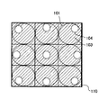
図の例においては、それぞれの画素に対する開口部104の位置として、互いに左右方向にシフトした6種類の開口マスク103が用意されている。そして、撮像素子100の全体は、紙面左側から右側へ徐々にシフトする開口マスク103をそれぞれ有する6つの視差画素を一組とする光電変換素子群が、二次元的かつ周期的に配列されている。つまり、撮像素子100は、一組の光電変換素子群を含む繰り返しパターン110が、周期的に敷き詰められて構成されていると言える。   In the example shown in the drawing, six types of opening masks 103 that are shifted in the left-right direction are prepared as the positions of the openings 104 for the respective pixels. The entire image sensor 100 has a two-dimensional and periodic array of photoelectric conversion element groups each including a set of six parallax pixels each having an aperture mask 103 that gradually shifts from the left side to the right side of the drawing. . That is, it can be said that the image sensor 100 is configured by periodically repeating a repeating pattern 110 including a set of photoelectric conversion element groups.

図4は、視差画素と被写体の関係を説明する概念図である。特に図4(a)は撮像素子100のうち撮影光軸21と直交する中心に配列されている繰り返しパターン110tの光電変換素子群を示し、図4(b)は周辺部分に配列されている繰り返しパターン110uの光電変換素子群を模式的に示している。図4(a)、(b)における被写体30は、撮影レンズ20に対して合焦位置に存在する。図4(c)は、図4(a)に対応して、撮影レンズ20に対して非合焦位置に存在する被写体31を捉えた場合の関係を模式的に示している。なお、後に言及するまでは、合焦位置に存在する被写体に対して取得される視差量を、理想値である0として説明する。   FIG. 4 is a conceptual diagram illustrating the relationship between the parallax pixels and the subject. In particular, FIG. 4A shows a photoelectric conversion element group of a repetitive pattern 110t arranged at the center orthogonal to the photographing optical axis 21 in the image pickup element 100, and FIG. The photoelectric conversion element group of the pattern 110u is typically shown. The subject 30 in FIGS. 4A and 4B is in the in-focus position with respect to the taking lens 20. FIG. 4C schematically shows a relationship when the subject 31 existing at the out-of-focus position with respect to the photographing lens 20 is captured corresponding to FIG. Until described later, the parallax amount acquired for the subject present at the in-focus position will be described as 0, which is an ideal value.

まず、撮影レンズ20が合焦状態に存在する被写体30を捉えている場合の、視差画素と被写体の関係を説明する。被写体光束は、撮影レンズ20の瞳を通過して撮像素子100へ導かれるが、被写体光束が通過する全体の断面領域に対して、6つの部分領域Pa〜Pfが規定されている。そして、例えば繰り返しパターン110t、110uを構成する光電変換素子群の紙面左端の画素は、拡大図からもわかるように、部分領域Pfから射出された被写体光束のみが光電変換素子108へ到達するように、開口マスク103の開口部104fの位置が定められている。同様に、右端の画素に向かって、部分領域Peに対応して開口部104eの位置が、部分領域Pdに対応して開口部104dの位置が、部分領域Pcに対応して開口部104cの位置が、部分領域Pbに対応して開口部104bの位置が、部分領域Paに対応して開口部104aの位置がそれぞれ定められている。   First, the relationship between the parallax pixels and the subject when the photographing lens 20 captures the subject 30 that is in focus will be described. The subject luminous flux passes through the pupil of the photographic lens 20 and is guided to the image sensor 100. Six partial areas Pa to Pf are defined for the entire cross-sectional area through which the subject luminous flux passes. For example, in the pixel at the left end of the sheet of the photoelectric conversion element group constituting the repetitive patterns 110t and 110u, only the subject luminous flux emitted from the partial region Pf reaches the photoelectric conversion element 108 as can be seen from the enlarged view. The position of the opening 104f of the opening mask 103 is determined. Similarly, toward the rightmost pixel, the position of the opening 104e corresponding to the partial area Pe, the position of the opening 104d corresponding to the partial area Pd, and the position of the opening 104c corresponding to the partial area Pc. However, the position of the opening 104b is determined corresponding to the partial area Pb, and the position of the opening 104a is determined corresponding to the partial area Pa.

別言すれば、例えば部分領域Pfと左端画素の相対的な位置関係によって定義される、部分領域Pfから射出される被写体光束の主光線Rfの傾きにより、開口部104fの位置が定められていると言っても良い。そして、合焦位置に存在する被写体30からの被写体光束を、開口部104fを介して光電変換素子108が受光する場合、その被写体光束は、点線で図示するように、光電変換素子108上で結像する。同様に、右端の画素に向かって、主光線Reの傾きにより開口部104eの位置が、主光線Rdの傾きにより開口部104dの位置が、主光線Rcの傾きにより開口部104cの位置が、主光線Rbの傾きにより開口部104bの位置が、主光線Raの傾きにより開口部104aの位置がそれぞれ定められていると言える。   In other words, the position of the opening 104f is determined by the inclination of the principal ray Rf of the subject light beam emitted from the partial region Pf, which is defined by the relative positional relationship between the partial region Pf and the leftmost pixel, for example. You can say. Then, when the photoelectric conversion element 108 receives the subject luminous flux from the subject 30 existing at the in-focus position via the opening 104f, the subject luminous flux is coupled on the photoelectric conversion element 108 as shown by the dotted line. Image. Similarly, toward the rightmost pixel, the position of the opening 104e is determined by the inclination of the principal ray Re, the position of the opening 104d is determined by the inclination of the principal ray Rd, and the position of the opening 104c is determined by the inclination of the principal ray Rc. It can be said that the position of the opening 104b is determined by the inclination of the light ray Rb, and the position of the opening 104a is determined by the inclination of the principal ray Ra.

図4(a)で示すように、合焦位置に存在する被写体30のうち、光軸21と交差する被写体30上の微小領域Otから放射される光束は、撮影レンズ20の瞳を通過して、繰り返しパターン110tを構成する光電変換素子群の各画素に到達する。すなわち、繰り返しパターン110tを構成する光電変換素子群の各画素は、それぞれ6つの部分領域Pa〜Pfを介して、一つの微小領域Otから放射される光束を受光している。微小領域Otは、繰り返しパターン110tを構成する光電変換素子群の各画素の位置ずれに対応する分だけの広がりを有するが、実質的には、ほぼ同一の物点と近似することができる。同様に、図4(b)で示すように、合焦位置に存在する被写体30のうち、光軸21から離間した被写体30上の微小領域Ouから放射される光束は、撮影レンズ20の瞳を通過して、繰り返しパターン110uを構成する光電変換素子群の各画素に到達する。すなわち、繰り返しパターン110uを構成する光電変換素子群の各画素は、それぞれ6つの部分領域Pa〜Pfを介して、一つの微小領域Ouから放射される光束を受光している。微小領域Ouも、微小領域Otと同様に、繰り返しパターン110uを構成する光電変換素子群の各画素の位置ずれに対応する分だけの広がりを有するが、実質的には、ほぼ同一の物点と近似することができる。   As shown in FIG. 4A, the light beam emitted from the minute region Ot on the subject 30 that intersects the optical axis 21 among the subject 30 existing at the in-focus position passes through the pupil of the photographing lens 20. Then, each pixel of the photoelectric conversion element group constituting the repetitive pattern 110t is reached. That is, each pixel of the photoelectric conversion element group constituting the repetitive pattern 110t receives a light beam emitted from one minute region Ot through each of the six partial regions Pa to Pf. Although the minute region Ot has an extent corresponding to the positional deviation of each pixel of the photoelectric conversion element group constituting the repetitive pattern 110t, it can be approximated to substantially the same object point. Similarly, as shown in FIG. 4B, the light beam emitted from the minute region Ou on the subject 30 that is separated from the optical axis 21 among the subject 30 that exists at the in-focus position passes through the pupil of the photographing lens 20. It passes through and reaches each pixel of the photoelectric conversion element group constituting the repetitive pattern 110u. That is, each pixel of the photoelectric conversion element group constituting the repetitive pattern 110u receives a light beam emitted from one minute region Ou through each of the six partial regions Pa to Pf. Similarly to the micro area Ot, the micro area Ou has an extent corresponding to the positional deviation of each pixel of the photoelectric conversion element group constituting the repetitive pattern 110u, but substantially the same object point. Can be approximated.

つまり、被写体30が合焦位置に存在する限りは、撮像素子100上における繰り返しパターン110の位置に応じて、光電変換素子群が捉える微小領域が異なり、かつ、光電変換素子群を構成する各画素は互いに異なる部分領域を介して同一の微小領域を捉えている。そして、それぞれの繰り返しパターン110において、対応する画素同士は同じ部分領域からの被写体光束を受光している。つまり、図においては、例えば繰り返しパターン110t、110uのそれぞれの左端の画素は、同じ部分領域Pfからの被写体光束を受光している。   In other words, as long as the subject 30 exists at the in-focus position, the minute area captured by the photoelectric conversion element group differs according to the position of the repetitive pattern 110 on the image sensor 100, and each pixel constituting the photoelectric conversion element group Captures the same minute region through different partial regions. In each repetitive pattern 110, corresponding pixels receive the subject luminous flux from the same partial area. That is, in the figure, for example, the leftmost pixel of each of the repeated patterns 110t and 110u receives the subject light flux from the same partial region Pf.

撮影光軸21と直交する中心に配列されている繰り返しパターン110tにおいて左端画素が部分領域Pfからの被写体光束を受光する開口部104fの位置と、周辺部分に配列されている繰り返しパターン110uにおいて左端画素が部分領域Pfからの被写体光束を受光する開口部104fの位置は厳密には異なる。しかしながら、機能的な観点からは、部分領域Pfからの被写体光束を受光するための開口マスクという点で、これらを同一種類の開口マスクとして扱うことができる。したがって、図4の例では、撮像素子100上に配列される視差画素のそれぞれは、6種類の開口マスクの一つを備えると言える。   In the repetitive pattern 110t arranged in the center orthogonal to the photographing optical axis 21, the left end pixel in the repetitive pattern 110u arranged in the peripheral portion and the position of the opening 104f where the left end pixel receives the subject light beam from the partial region Pf. However, the position of the opening 104f that receives the subject luminous flux from the partial region Pf is strictly different. However, from a functional point of view, these can be treated as the same type of aperture mask in terms of an aperture mask for receiving the subject light flux from the partial region Pf. Therefore, in the example of FIG. 4, it can be said that each of the parallax pixels arranged on the image sensor 100 includes one of six types of aperture masks.

次に、撮影レンズ20が非合焦状態に存在する被写体31を捉えている場合の、視差画素と被写体の関係を説明する。この場合も、非合焦位置に存在する被写体31からの被写体光束は、撮影レンズ20の瞳の6つの部分領域Pa〜Pfを通過して、撮像素子100へ到達する。ただし、非合焦位置に存在する被写体31からの被写体光束は、光電変換素子108上ではなく他の位置で結像する。例えば、図4(c)に示すように、被写体31が被写体30よりも撮像素子100に対して遠い位置に存在すると、被写体光束は、光電変換素子108よりも被写体31側で結像する。逆に、被写体31が被写体30よりも撮像素子100に対して近い位置に存在すると、被写体光束は、光電変換素子108よりも被写体31とは反対側で結像する。   Next, the relationship between the parallax pixels and the subject when the photographing lens 20 captures the subject 31 existing in the out-of-focus state will be described. Also in this case, the subject luminous flux from the subject 31 present at the out-of-focus position passes through the six partial areas Pa to Pf of the pupil of the photographing lens 20 and reaches the image sensor 100. However, the subject light flux from the subject 31 existing at the out-of-focus position forms an image at another position, not on the photoelectric conversion element 108. For example, as illustrated in FIG. 4C, when the subject 31 exists at a position farther from the imaging element 100 than the subject 30, the subject light flux forms an image on the subject 31 side with respect to the photoelectric conversion element 108. Conversely, when the subject 31 is present at a position closer to the image sensor 100 than the subject 30, the subject luminous flux forms an image on the opposite side of the subject 31 from the photoelectric conversion element 108.

したがって、非合焦位置に存在する被写体31のうち、微小領域Ot'から放射される被写体光束は、6つの部分領域Pa〜Pfのいずれを通過するかにより、異なる組の繰り返しパターン110における対応画素に到達する。例えば、部分領域Pdを通過した被写体光束は、図4(c)の拡大図に示すように、主光線Rd'として、繰り返しパターン110t'に含まれる、開口部104dを有する光電変換素子108へ入射する。そして、微小領域Ot'から放射された被写体光束であっても、他の部分領域を通過した被写体光束は、繰り返しパターン110t'に含まれる光電変換素子108へは入射せず、他の繰り返しパターンにおける対応する開口部を有する光電変換素子108へ入射する。換言すると、繰り返しパターン110t'を構成する各光電変換素子108へ到達する被写体光束は、被写体31の互いに異なる微小領域から放射された被写体光束である。すなわち、開口部104dに対応する108へは主光線をRd'とする被写体光束が入射し、他の開口部に対応する光電変換素子108へは主光線をRa、Rb、Rc、Re、Rfとする被写体光束が入射するが、これらの被写体光束は、被写体31の互いに異なる微小領域から放射された被写体光束である。このような関係は、図4(b)における周辺部分に配列されている繰り返しパターン110uにおいても同様である。 Therefore, the subject luminous flux emitted from the minute region Ot ′ among the subjects 31 existing at the out-of-focus position depends on which of the six partial regions Pa to Pf, the corresponding pixels in the different sets of repetitive patterns 110. To reach. For example, as shown in the enlarged view of FIG. 4C, the subject luminous flux that has passed through the partial region Pd is incident on the photoelectric conversion element 108 having the opening 104d included in the repeated pattern 110t ′ as the principal ray Rd ′. To do. Even if the subject light beam is emitted from the minute region Ot ′, the subject light beam that has passed through another partial region does not enter the photoelectric conversion element 108 included in the repetitive pattern 110t ′, and the repetitive pattern in the other repetitive pattern. The light enters the photoelectric conversion element 108 having a corresponding opening. In other words, the subject luminous flux reaching each photoelectric conversion element 108 constituting the repetitive pattern 110t ′ is a subject luminous flux radiated from different minute areas of the subject 31. That is, a subject luminous flux having a principal ray as Rd ′ is incident on 108 corresponding to the opening 104d, and the principal rays are incident on Ra + , Rb + , Rc + , Re to the photoelectric conversion elements 108 corresponding to the other openings. +, although subject light flux to Rf + is incident, these object light is a subject light flux emitted from different micro region of the object 31. Such a relationship is the same in the repeated pattern 110u arranged in the peripheral portion in FIG.

すると、撮像素子100の全体で見た場合、例えば、開口部104aに対応する光電変換素子108で捉えた被写体像Aと、開口部104dに対応する光電変換素子108で捉えた被写体像Dは、合焦位置に存在する被写体に対する像であれば互いにずれが無く、非合焦位置に存在する被写体に対する像であればずれが生じることになる。そして、そのずれは、非合焦位置に存在する被写体が合焦位置に対してどちら側にどれだけずれているかにより、また、部分領域Paと部分領域Pdの距離により、方向と量が定まる。つまり、被写体像Aと被写体像Dは、互いに視差像となる。この関係は、他の開口部に対しても同様であるので、開口部104aから104fに対応して、6つの視差像が形成されることになる。   Then, when viewed as a whole of the imaging element 100, for example, the subject image A captured by the photoelectric conversion element 108 corresponding to the opening 104a and the subject image D captured by the photoelectric conversion element 108 corresponding to the opening 104d are: If the image is for the subject present at the in-focus position, there is no shift, and if the image is for the subject present at the out-of-focus position, there is a shift. Then, the direction and amount of the shift are determined by how much the subject existing at the out-of-focus position is shifted from the focus position and by the distance between the partial area Pa and the partial area Pd. That is, the subject image A and the subject image D are parallax images. Since this relationship is the same for the other openings, six parallax images are formed corresponding to the openings 104a to 104f.

したがって、このように構成されたそれぞれの繰り返しパターン110において、互いに対応する画素の出力を寄せ集めると、視差画像が得られる。つまり、6つの部分領域Pa〜Pfうちの特定の部分領域から射出された被写体光束を受光した画素の出力は、視差画像を形成する。   Therefore, when the outputs of the pixels corresponding to each other in each of the repetitive patterns 110 configured in this way are collected, a parallax image is obtained. That is, the output of the pixel that has received the subject light beam emitted from a specific partial area among the six partial areas Pa to Pf forms a parallax image.

図5は、視差画像を生成する処理を説明する概念図である。図は、左列から順に、開口部104fに対応する視差画素の出力を集めて生成される視差画像データIm_fの生成の様子、開口部104eの出力による視差画像データIm_eの生成の様子、開口部104dの出力による視差画像データIm_dの生成の様子、開口部104cの出力による視差画像データIm_cの生成の様子、開口部104bの出力による視差画像データIm_bの生成の様子、開口部104aの出力による視差画像データIm_aの生成の様子を表す。まず開口部104fの出力による視差画像データIm_fの生成の様子について説明する。   FIG. 5 is a conceptual diagram illustrating processing for generating a parallax image. The figure shows, in order from the left column, the generation of the parallax image data Im_f generated by collecting the outputs of the parallax pixels corresponding to the opening 104f, the generation of the parallax image data Im_e by the output of the opening 104e, the opening State of generation of parallax image data Im_d by output of 104d, state of generation of parallax image data Im_c by output of opening 104c, state of generation of parallax image data Im_b by output of opening 104b, parallax by output of opening 104a This represents how the image data Im_a is generated. First, how the parallax image data Im_f is generated by the output of the opening 104f will be described.

6つの視差画素を一組とする光電変換素子群から成る繰り返しパターン110は、横一列に配列されている。したがって、開口部104fを有する視差画素は、撮像素子100上において、左右方向に6画素おき、かつ、上下方向に連続して存在する。これら各画素は、上述のようにそれぞれ異なる微小領域からの被写体光束を受光している。したがって、これらの視差画素の出力を寄せ集めて配列すると、視差画像が得られる。   A repeating pattern 110 composed of a group of photoelectric conversion elements each including six parallax pixels is arranged in a horizontal row. Accordingly, the parallax pixels having the opening 104f exist every six pixels in the left-right direction and continuously in the vertical direction on the image sensor 100. Each of these pixels receives the subject luminous flux from different microregions as described above. Therefore, when the outputs of these parallax pixels are collected and arranged, a parallax image is obtained.

しかし、本実施形態における撮像素子100の各画素は正方画素であるので、単に寄せ集めただけでは、横方向の画素数が1/6に間引かれた結果となり、縦長の画像データが生成されてしまう。そこで、補間処理を施して横方向に6倍の画素数とすることにより、本来のアスペクト比の画像として視差画像データIm_fを生成する。ただし、そもそも補間処理前の視差画像データが横方向に1/6に間引かれた画像であるので、横方向の解像度は、縦方向の解像度よりも低下している。つまり、生成される視差画像データの数と、解像度の向上は相反関係にあると言える。   However, since each pixel of the image sensor 100 according to the present embodiment is a square pixel, simply gathering results in the result that the number of pixels in the horizontal direction is reduced to 1/6, and vertically long image data is generated. End up. Therefore, by performing an interpolation process to obtain the number of pixels 6 times in the horizontal direction, the parallax image data Im_f is generated as an image with an original aspect ratio. However, since the parallax image data before the interpolation processing is an image that is thinned by 1/6 in the horizontal direction, the resolution in the horizontal direction is lower than the resolution in the vertical direction. That is, it can be said that the number of generated parallax image data and the improvement in resolution are in a conflicting relationship.

同様にして、視差画像データIm_e〜視差画像データIm_aが得られる。すなわち、デジタルカメラ10は、横方向に視差を有する6視点の視差画像を生成することができる。   Similarly, parallax image data Im_e to parallax image data Im_a are obtained. That is, the digital camera 10 can generate a six-view parallax image having parallax in the horizontal direction.

上記の例では、横一列を繰り返しパターン110として周期的に配列される例を説明したが、繰り返しパターン110はこれに限らない。図6は、繰り返しパターン110の他の例を示す図である。   In the above example, the example in which one horizontal row is periodically arranged as the repeating pattern 110 has been described, but the repeating pattern 110 is not limited to this. FIG. 6 is a diagram illustrating another example of the repeated pattern 110.

図6(a)は、縦6画素を繰り返しパターン110とした例である。ただし、それぞれの開口部104は、紙面上端の視差画素から下に向かって、紙面左側から右側へ徐々にシフトするように位置が定められている。このように配列された繰り返しパターン110によっても、横方向に視差を与える6視点の視差画像を生成することができる。この場合は、図3の繰り返しパターン110に比較すると、縦方向の解像度を犠牲にする代わりに横方向の解像度を維持する繰り返しパターンであると言える。   FIG. 6A shows an example in which the vertical 6 pixels are the repeated pattern 110. However, the positions of the respective openings 104 are determined so as to gradually shift from the left side to the right side of the drawing from the parallax pixel at the top of the drawing to the bottom. Also with the repeated pattern 110 arranged in this way, it is possible to generate a six-view parallax image that gives parallax in the horizontal direction. In this case, compared to the repetitive pattern 110 in FIG. 3, it can be said that the repetitive pattern maintains the horizontal resolution instead of sacrificing the vertical resolution.

図6(b)は、斜め方向に隣接する6画素を繰り返しパターン110とした例である。それぞれの開口部104は、紙面左上端の視差画素から右下に向かって、紙面左側から右側へ徐々にシフトするように位置が定められている。このように配列された繰り返しパターン110によっても、横方向に視差を与える6視点の視差画像を生成することができる。この場合は、図3の繰り返しパターン110に比較すると、縦方向の解像度および横方向の解像度をある程度維持しつつ、視差画像の数を増やす繰り返しパターンであると言える。   FIG. 6B shows an example in which six pixels adjacent in the oblique direction are used as the repeated pattern 110. The positions of the openings 104 are determined so as to gradually shift from the left side to the right side of the drawing from the parallax pixel at the upper left corner of the drawing toward the lower right. Also with the repeated pattern 110 arranged in this way, it is possible to generate a six-view parallax image that gives parallax in the horizontal direction. In this case, compared to the repetitive pattern 110 in FIG. 3, it can be said that the repetitive pattern increases the number of parallax images while maintaining the vertical resolution and the horizontal resolution to some extent.

図3の繰り返しパターン110、および図6(a)(b)の繰り返しパターン110をそれぞれ比較すると、いずれも6視点の視差画像を生成する場合において、視差画像でない全体から一枚の画像を出力する場合の解像度に対し、縦方向、横方向のいずれの方向の解像度を犠牲にするかの違いであると言える。図3の繰り返しパターン110の場合は、横方向の解像度を1/6とする構成である。図6(a)の繰り返しパターン110の場合は、縦方向の解像度を1/6とする構成である。また、図6(b)の繰り返しパターン110の場合は、縦方向を1/3、横方向を1/2とする構成である。いずれの場合も、一つのパターン内には、各画素に対応して開口部104a〜104fが一つずつ設けられており、それぞれが対応する部分領域Pa〜Pfのいずれかから被写体光束を受光するように構成されている。したがって、いずれの繰り返しパターン110であっても視差量は同等である。   When the repeating pattern 110 in FIG. 3 and the repeating pattern 110 in FIGS. 6A and 6B are respectively compared, when generating parallax images with six viewpoints, a single image is output from the whole that is not a parallax image. It can be said that this is the difference between sacrificing the resolution in the vertical direction and the horizontal direction with respect to the resolution in the case. In the case of the repetitive pattern 110 in FIG. 3, the horizontal resolution is set to 1/6. In the case of the repetitive pattern 110 in FIG. 6A, the vertical resolution is 1/6. 6B has a configuration in which the vertical direction is 1/3 and the horizontal direction is 1/2. In any case, one opening 104a to 104f is provided corresponding to each pixel in one pattern, and the subject luminous flux is received from one of the corresponding partial areas Pa to Pf. It is configured as follows. Accordingly, the parallax amount is the same for any of the repeated patterns 110.

上述の例では、左右方向に視差を与える視差画像を生成する場合について説明したが、もちろん上下方向に視差を与える視差画像を生成することもできるし、上下左右の二次元方向に視差を与える視差画像を生成することもできる。図7は、二次元的な繰り返しパターン110の例を示す図である。   In the above-described example, the case of generating a parallax image that gives parallax in the left-right direction has been described. Of course, a parallax image that gives parallax in the vertical direction can also be generated, and parallax that gives parallax in the two-dimensional direction in the vertical and horizontal directions An image can also be generated. FIG. 7 is a diagram illustrating an example of a two-dimensional repetitive pattern 110.

図7の例によれば、縦6画素横6画素の36画素を一組の光電変換素子群として繰り返しパターン110を形成する。それぞれの画素に対する開口部104の位置として、互いに上下左右方向にシフトした36種類の開口マスク103が用意されている。具体的には、各開口部104は、繰り返しパターン110の上端画素から下端画素に向かって、上側から下側へ徐々にシフトすると同時に、左端画素から右端画素に向かって、左側から右側へ徐々にシフトするように位置決めされている。   According to the example of FIG. 7, the repetitive pattern 110 is formed by using 36 pixels of 6 pixels in the vertical direction and 6 pixels in the horizontal direction as a set of photoelectric conversion element groups. As the position of the opening 104 for each pixel, 36 types of opening masks 103 that are shifted in the vertical and horizontal directions are prepared. Specifically, each opening 104 gradually shifts from the upper side to the lower side from the upper end pixel to the lower end pixel of the repetitive pattern 110, and at the same time, gradually from the left end pixel to the right end pixel, from the left side to the right side. Positioned to shift.

このような繰り返しパターン110を有する撮像素子100は、上下方向および左右方向に視差を与える、36視点の視差画像を出力することができる。もちろん図7の例に限らず、さまざまな視点数の視差画像を出力するように繰り返しパターン110を定めることができる。   The image sensor 100 having such a repeating pattern 110 can output a parallax image of 36 viewpoints that gives parallax in the vertical direction and the horizontal direction. Of course, the pattern 110 is not limited to the example in FIG. 7, and the repetitive pattern 110 can be determined so as to output parallax images with various viewpoints.

以上の説明においては、開口部104の形状として矩形を採用した。特に、横方向に視差を与える配列においては、シフトさせる方向である左右方向の幅よりも、シフトさせない上下方向の幅を広くすることにより、光電変換素子108へ導く光量を確保している。しかし、開口部104の形状は矩形に限定されない。   In the above description, a rectangle is adopted as the shape of the opening 104. In particular, in an array that gives parallax in the horizontal direction, the amount of light guided to the photoelectric conversion element 108 is ensured by making the width in the vertical direction that is not shifted wider than the width in the horizontal direction that is the shift direction. However, the shape of the opening 104 is not limited to a rectangle.

図8は、開口部104の他の形状を説明する図である。図においては、開口部104の形状を円形とした。円形とした場合、半球形状であるマイクロレンズ101との相対的な関係から、予定外の被写体光束が迷光となって光電変換素子108へ入射することを防ぐことができる。   FIG. 8 is a diagram illustrating another shape of the opening 104. In the figure, the shape of the opening 104 is circular. In the case of a circular shape, an unscheduled subject light beam can be prevented from entering the photoelectric conversion element 108 as stray light because of the relative relationship with the microlens 101 having a hemispherical shape.

次に、カラーフィルタ102と視差画像について説明する。図9は、ベイヤー配列を説明する図である。図示するように、ベイヤー配列は、緑フィルタが左上と右下の2画素に、赤フィルタが左下の1画素に、青フィルタが右上の1画素に割り当てられる配列である。ここでは、緑フィルタが割り当てられた左上の画素をGb画素と、同じく緑色フィルタが割り当てられた右下の画素をGr画素とする。また、赤色フィルタが割り当てられた画素をR画素と、青色が割り当てられた画素をB画素とする。そして、Gb画素およびB画素が並ぶ横方向をGb行とし、R画素およびGr画素が並ぶ横方向をGr行とする。また、Gb画素およびR画素が並ぶ縦方向をGb列とし、B画素およびGr画素が並ぶ縦方向をGr列とする。   Next, the color filter 102 and the parallax image will be described. FIG. 9 is a diagram illustrating the Bayer arrangement. As shown in the figure, the Bayer array is an array in which the green filter is assigned to the upper left and lower right pixels, the red filter is assigned to the lower left pixel, and the blue filter is assigned to the upper right pixel. Here, the upper left pixel to which the green filter is assigned is the Gb pixel, and the lower right pixel to which the green filter is assigned is the Gr pixel. In addition, a pixel to which a red filter is assigned is an R pixel, and a pixel to which blue is assigned is a B pixel. A horizontal direction in which Gb pixels and B pixels are arranged is defined as Gb row, and a horizontal direction in which R pixels and Gr pixels are arranged is defined as Gr row. A vertical direction in which Gb pixels and R pixels are arranged is a Gb column, and a vertical direction in which B pixels and Gr pixels are arranged is a Gr column.

このようなカラーフィルタ102の配列に対して、視差画素と視差なし画素を、何色の画素にどのような周期で割り振っていくかにより、膨大な数の繰り返しパターン110が設定され得る。視差なし画素の出力を集めれば、通常の撮影画像と同じく視差のない撮影画像データを生成することができる。したがって、相対的に視差なし画素の割合を増やせば、解像度の高い2D画像を出力させることができる。この場合、視差画素は相対的に少ない割合となるので、複数の視差画像からなる3D画像としては画質が低下する。逆に、視差画素の割合を増やせば、3D画像としては画質が向上するが、視差なし画素は相対的に減少するので、解像度の低い2D画像が出力される。   With respect to such an arrangement of the color filters 102, an enormous number of repetitive patterns 110 can be set depending on what color pixels the parallax pixels and non-parallax pixels are allocated to. If the outputs of pixels without parallax are collected, photographic image data having no parallax can be generated in the same way as normal photographic images. Therefore, if the ratio of pixels without parallax is relatively increased, a 2D image with high resolution can be output. In this case, since the number of parallax pixels is relatively small, the image quality is degraded as a 3D image including a plurality of parallax images. Conversely, if the ratio of the parallax pixels is increased, the image quality is improved as a 3D image, but the non-parallax pixels are relatively reduced, so that a 2D image with low resolution is output.

このようなトレードオフの関係において、何れの画素を視差画素とするか、あるいは視差なし画素とするかにより、様々な特徴を有する繰り返しパターン110が設定される。図10は、ベイヤー配列に対する視差画素の割り振りについて、視差画素の種類が2つである場合のバリエーションを説明する図である。この場合の視差画素は、開口部104が中心よりも左側に偏心した視差L画素と、同じく右側に偏心した視差R画素を想定している。つまり、このような視差画素から出力される2視点の視差画像は、いわゆる立体視を実現する。   In such a trade-off relationship, a repetitive pattern 110 having various characteristics is set depending on which pixel is a parallax pixel or a non-parallax pixel. FIG. 10 is a diagram illustrating a variation in the case where there are two types of parallax pixels with respect to the allocation of parallax pixels to the Bayer array. In this case, the parallax pixels are assumed to be a parallax L pixel whose opening 104 is decentered to the left of the center and a parallax R pixel decentered to the right. That is, the two viewpoint parallax images output from such parallax pixels realize so-called stereoscopic vision.

それぞれの繰り返しパターンに対する特徴の説明は図に示す通りである。例えば、視差なし画素が多く割り振られていれば高解像度の2D画像データとなり、RGBのいずれの画素に対しても均等に割り振られていれば、色ずれの少ない高画質の2D画像データとなる。一方、視差画素が多く割り振られていれば高解像度の3D画像データとなり、RGBのいずれの画素に対しても均等に割り振られていれば、3D画像でありながら、色再現性の良い高品質のカラー画像データとなる。   The description of the features for each repetitive pattern is as shown in the figure. For example, if many non-parallax pixels are allocated, high-resolution 2D image data is obtained, and if all pixels of RGB are equally allocated, high-quality 2D image data with little color shift is obtained. On the other hand, if a large number of parallax pixels are allocated, high-resolution 3D image data is obtained, and if all the RGB pixels are allocated equally, a high-quality image with good color reproducibility can be obtained while being a 3D image. Color image data.

以下にいくつかのバリエーションについて説明する。図11は、バリエーションの一例を示す図である。図11のバリエーションは、図10における繰り返しパターン分類A−1に相当する。   Some variations are described below. FIG. 11 is a diagram illustrating an example of a variation. The variation in FIG. 11 corresponds to the repeated pattern classification A-1 in FIG.

図の例においては、ベイヤー配列と同じ4画素を繰り返しパターン110とする。R画素とB画素は視差なし画素であり、Gb画素を視差L画素に、Gr画素を視差R画素に割り当てる。この場合、同一の繰り返しパターン110に含まれる視差L画素と視差R画素が、被写体が合焦位置に存在するときに、同じ微小領域から放射される光束を受光するように開口部104が定められる。   In the example of the figure, the same four pixels as the Bayer array are used as the repeated pattern 110. The R pixel and the B pixel are non-parallax pixels, and the Gb pixel is assigned to the parallax L pixel and the Gr pixel is assigned to the parallax R pixel. In this case, the opening 104 is defined so that the parallax L pixel and the parallax R pixel included in the same repetitive pattern 110 receive the light beam emitted from the same minute area when the subject is in the in-focus position. .

図の例においては、視感度の高い緑画素であるGb画素およびGr画素を視差画素として用いるので、コントラストの高い視差画像を得ることが期待できる。また、同じ緑色画素であるGb画素およびGr画素を視差画素として用いるので、これら2つの出力から視差のない出力に変換演算がし易く、視差なし画素であるR画素およびB画素の出力と共に、高画質の2D画像データを生成できる。   In the example of the figure, Gb pixels and Gr pixels, which are green pixels with high visibility, are used as parallax pixels, so that it is expected to obtain a parallax image with high contrast. In addition, since the Gb pixel and the Gr pixel which are the same green pixels are used as the parallax pixels, it is easy to perform a conversion operation from these two outputs to an output having no parallax, and the output of the R pixel and the B pixel which are non-parallax pixels is high. High-quality 2D image data can be generated.

図12は、他のバリエーションの一例を示す図である。図12のバリエーションは、図10における繰り返しパターン分類B−1に相当する。   FIG. 12 is a diagram illustrating an example of another variation. The variation in FIG. 12 corresponds to the repeated pattern classification B-1 in FIG.

図の例においては、ベイヤー配列の4画素が左右に2組続く8画素を繰り返しパターン110とする。8画素のうち、左側のGb画素に視差L画素を、右側のGb画素に視差R画素を割り当てる。このような配列においては、Gr画素を視差なし画素としたことにより、図10の例よりも、更に2D画像の高画質化が望める。   In the example shown in the figure, the repeated pattern 110 is 8 pixels in which 4 pixels in the Bayer array are two sets on the left and right. Among the eight pixels, the parallax L pixel is assigned to the left Gb pixel, and the parallax R pixel is assigned to the right Gb pixel. In such an arrangement, the Gr pixel is a non-parallax pixel, so that higher image quality of the 2D image can be expected than in the example of FIG.

図13は、更に他のバリエーションの一例を示す図である。図13のバリエーションは、図10における繰り返しパターン分類D−1に相当する。   FIG. 13 is a diagram illustrating an example of still another variation. The variation in FIG. 13 corresponds to the repeated pattern classification D-1 in FIG.

図の例においては、ベイヤー配列の4画素が左右に2組続く8画素を繰り返しパターン110とする。8画素のうち、左側のGb画素に視差L画素を、右側のGb画素に視差R画素を割り当てる。さらに、左側のR画素に視差L画素を、右側のR画素に視差R画素を割り当てる。さらに、左側のB画素に視差L画素を、右側のB画素に視差R画素を割り当てる。2つのGr画素には視差なし画素を割り当てる。   In the example shown in the figure, the repeated pattern 110 is 8 pixels in which 4 pixels in the Bayer array are two sets on the left and right. Among the eight pixels, the parallax L pixel is assigned to the left Gb pixel, and the parallax R pixel is assigned to the right Gb pixel. Further, the parallax L pixel is assigned to the left R pixel, and the parallax R pixel is assigned to the right R pixel. Further, a parallax L pixel is assigned to the left B pixel, and a parallax R pixel is assigned to the right B pixel. Non-parallax pixels are assigned to the two Gr pixels.

2つのGb画素に割り当てられた視差L画素と視差R画素は、被写体が合焦位置に存在するときに、一つの微小領域から放射される光束を受光する。また、2つのR画素に割り当てられた視差L画素と視差R画素は、Gb画素のそれとは異なる一つの微小領域から放射される光束を受光し、2つのB画素に割り当てられた視差L画素と視差R画素は、Gb画素およびR画素のそれとは異なる一つの微小領域から放射される光束を受光する。したがって、図12の例に比較して、3D画像としての解像度が縦方向に3倍となる。しかも、RGBの3色の出力が得られるので、カラー画像としての3D画像として高品質である。   The parallax L pixel and the parallax R pixel assigned to the two Gb pixels receive the light beam emitted from one minute region when the subject is in the in-focus position. In addition, the parallax L pixel and the parallax R pixel assigned to the two R pixels receive a light beam emitted from one minute region different from that of the Gb pixel, and the parallax L pixel assigned to the two B pixels The parallax R pixel receives a light beam emitted from one minute region different from that of the Gb pixel and the R pixel. Therefore, compared with the example of FIG. 12, the resolution as a 3D image is tripled in the vertical direction. Moreover, since RGB three-color output can be obtained, it is a high-quality 3D image as a color image.

なお、上述のように視差画素の種類を2つにすれば2視点の視差画像が得られるが、もちろん視差画素の種類は、出力したい視差画像数に合わせて、図3、図7、図8などで説明したような様々な数を採用し得る。視点数が増えていっても、さまざまな繰り返しパターン110を形成することができる。したがって、仕様、目的等に応じた繰り返しパターン110を選択することができる。   As described above, if two types of parallax pixels are used, parallax images of two viewpoints can be obtained. Of course, the types of parallax pixels are set in accordance with the number of parallax images to be output, as shown in FIGS. Various numbers as described above can be adopted. Even if the number of viewpoints is increased, various repeated patterns 110 can be formed. Therefore, it is possible to select the repetitive pattern 110 according to the specification, purpose, and the like.

上述の例では、カラーフィルタ配列としてベイヤー配列を採用した場合について説明したが、もちろん他のカラーフィルタ配列であっても差し支えない。このとき、一組の光電変換素子群を構成する視差画素のそれぞれは、互いに異なる部分領域を向く開口部104を有する開口マスク103を備えると良い。   In the above-described example, the case where the Bayer array is adopted as the color filter array has been described. Of course, other color filter arrays may be used. At this time, each of the parallax pixels constituting the set of photoelectric conversion element groups may include an opening mask 103 having opening portions 104 facing different partial regions.

したがって、撮像素子100は、入射光を電気信号に光電変換する、二次元的に配列された光電変換素子108と、光電変換素子108の少なくとも一部のそれぞれに一対一に対応して設けられた開口マスク103と、光電変換素子108の少なくとも一部のそれぞれに一対一に対応して設けられたカラーフィルタ102とを備え、隣接するn個(nは3以上の整数)の光電変換素子108のうち、少なくとも2つ(3つ以上であっても良い)に対応して設けられたそれぞれの開口マスク103の開口部104は、互いに異なる波長帯域を透過させる少なくとも3種類のカラーフィルタ102から構成されるカラーフィルターパターンの一パターン内に含まれると共に、入射光の断面領域内の互いに異なる部分領域からの光束をそれぞれ通過させるように位置づけられ、n個の光電変換素子108を一組とする光電変換素子群が周期的に配列されていれば良い。   Therefore, the image sensor 100 is provided in a one-to-one correspondence with each of at least a part of the photoelectric conversion elements 108 and the photoelectric conversion elements 108 that are two-dimensionally arranged to photoelectrically convert incident light into electric signals. The aperture mask 103 and the color filters 102 provided in a one-to-one correspondence with each of at least a part of the photoelectric conversion elements 108 are provided, and n adjacent n (n is an integer of 3 or more) photoelectric conversion elements 108. Of these, the openings 104 of the respective opening masks 103 provided corresponding to at least two (may be three or more) are composed of at least three types of color filters 102 that transmit different wavelength bands. The color filter pattern is included in one pattern and the light beams from different partial areas in the cross-sectional area of the incident light pass through each. So as positioned, the photoelectric conversion element group for the n-number of photoelectric conversion elements 108 and a set is only to be periodically arranged.

図14は、他のカラーフィルタ配列を説明する図である。図示するように、他のカラーフィルタ配列は、図9で示したベイヤー配列のGr画素を緑フィルタが割り当てられるG画素として維持する一方、Gb画素をカラーフィルタが割り当てられないW画素に変更した配列である。なお、W画素は、上述のように、可視光のおよそ全ての波長帯域を透過させるように、着色を施さない透明フィルタが配列されていても良い。   FIG. 14 is a diagram for explaining another color filter arrangement. As shown in the figure, the other color filter array maintains the Gr pixels in the Bayer array shown in FIG. 9 as G pixels to which the green filter is assigned, while changing the Gb pixels to W pixels to which no color filter is assigned. It is. Note that, as described above, the W pixel may be arranged with a transparent filter that is not colored so as to transmit substantially all the wavelength band of visible light.

このようなW画素を含むカラーフィルタ配列を採用すれば、撮像素子が出力するカラー情報の精度は若干低下するものの、W画素が受光する光量はカラーフィルタが設けられている場合に比較して多いので、精度の高い輝度情報を取得できる。W画素の出力を寄せ集めれば、モノクロ画像を形成することもできる。   If such a color filter array including W pixels is adopted, the accuracy of the color information output from the image sensor is slightly reduced, but the amount of light received by the W pixels is larger than that when a color filter is provided. Therefore, highly accurate luminance information can be acquired. A monochrome image can also be formed by gathering the outputs of W pixels.

W画素を含むカラーフィルタ配列の場合、視差画素と視差なし画素の繰り返しパターン110は、さらなるバリエーションが存在する。例えば、比較的暗い環境下で撮影された画像であっても、カラー画素から出力された画像に比較してW画素から出力された画像であれば、被写体像のコントラストが高い。そこで、W画素に視差画素を割り振れば、複数の視差画像間で行うマッチング処理において、精度の高い演算結果が期待できる。後述するように、マッチング処理は、視差量を取得する処理の一環として実行される。したがって、2D画像の解像度および視差画像の画質への影響に加え、抽出される他の情報への利害得失も考慮して、視差画素と視差なし画素の繰り返しパターン110が設定される。   In the case of a color filter array including W pixels, there are further variations in the repeating pattern 110 of parallax pixels and non-parallax pixels. For example, even if the image is captured in a relatively dark environment, the contrast of the subject image is higher if the image is output from the W pixel as compared to the image output from the color pixel. Therefore, if a parallax pixel is assigned to a W pixel, a highly accurate calculation result can be expected in a matching process performed between a plurality of parallax images. As will be described later, the matching process is executed as part of the process of acquiring the parallax amount. Therefore, in addition to the influence on the resolution of the 2D image and the image quality of the parallax image, the repetitive pattern 110 of the parallax pixels and the non-parallax pixels is set in consideration of the interest in other extracted information.

図15は、図14の他のカラーフィルタ配列を採用する場合の、W画素と視差画素の配列の一例を示す図である。図15のバリエーションは、ベイヤー配列における図12の繰り返しパターン分類B−1に類似するので、ここではB'−1とする。図の例においては、他のカラーフィルタ配列の4画素が左右に2組続く8画素を繰り返しパターン110とする。8画素のうち、左側のW画素に視差L画素を、右側のW画素に視差R画素を割り当てる。このような配列において撮像素子100は、視差画像をモノクロ画像として出力し、2D画像をカラー画像として出力する。   FIG. 15 is a diagram illustrating an example of an array of W pixels and parallax pixels when another color filter array of FIG. 14 is employed. The variation in FIG. 15 is similar to the repeated pattern classification B-1 in FIG. In the example shown in the figure, the repeated pattern 110 is an eight pixel in which two sets of four pixels in other color filter arrays continue to the left and right. Among the eight pixels, the parallax L pixel is assigned to the left W pixel, and the parallax R pixel is assigned to the right W pixel. In such an arrangement, the image sensor 100 outputs a parallax image as a monochrome image and outputs a 2D image as a color image.

この場合、撮像素子100は、入射光を電気信号に光電変換する、二次元的に配列された光電変換素子108と、光電変換素子108の少なくとも一部のそれぞれに一対一に対応して設けられた開口マスク103と、光電変換素子108の少なくとも一部のそれぞれに一対一に対応して設けられたカラーフィルタ102とを有し、隣接するn個(nは4以上の整数)の光電変換素子108のうち、少なくとも2つに対応して設けられたそれぞれの開口マスク103の開口部104は、互いに異なる波長帯域を透過させる少なくとも3種類のカラーフィルタ102から構成されるカラーフィルターパターンの一パターン内には含まれず、かつ、入射光の断面領域内の互いに異なる部分領域からの光束をそれぞれ通過させるように位置づけられ、n個の光電変換素子108を一組とする光電変換素子群が周期的に配列されていれば良い。   In this case, the image sensor 100 is provided in a one-to-one correspondence with each of the two-dimensionally arranged photoelectric conversion elements 108 that photoelectrically convert incident light into electric signals and at least a part of the photoelectric conversion elements 108. And n adjacent n (n is an integer of 4 or more) photoelectric conversion elements each having an opening mask 103 and a color filter 102 provided in a one-to-one correspondence with each of at least a part of the photoelectric conversion element 108. The openings 104 of the respective opening masks 103 provided corresponding to at least two out of 108 are in one pattern of a color filter pattern composed of at least three kinds of color filters 102 that transmit different wavelength bands. And is positioned so as to pass light beams from different partial areas in the cross-sectional area of the incident light, The photoelectric conversion element group for a number of photoelectric conversion elements 108 and a set is only to be periodically arranged.

ここで、モノクロ画像としての視差画像の生成と、カラー画像としての2D画像の生成について説明する。   Here, generation of a parallax image as a monochrome image and generation of a 2D image as a color image will be described.

図16は、視差画像と2D画像の生成過程を示す概念図である。図示するように、視差L画素の出力が、撮像素子100上の相対的な位置関係を維持しながら寄せ集められて、L画像データが生成される。一つの繰り返しパターン110に含まれる視差L画素は一つであるので、L画像データを形成する各視差L画素は、それぞれ異なる繰り返しパターン110から寄せ集められていると言える。すなわち、寄せ集められたそれぞれの視差L画素の出力は、被写体の互いに異なる微小領域から放射された光が光電変換された結果であるので、L画像データは、特定の視点(L視点)から被写体を捉えた一つの視差画像データとなる。そして、視差L画素は、W画素に割り振られているので、L画像データは、カラー情報を持たず、モノクロ画像として生成される。   FIG. 16 is a conceptual diagram illustrating a process of generating a parallax image and a 2D image. As shown in the figure, the outputs of the parallax L pixels are gathered together while maintaining the relative positional relationship on the image sensor 100, and L image data is generated. Since one parallax L pixel is included in one repetitive pattern 110, it can be said that the parallax L pixels forming the L image data are collected from different repetitive patterns 110. That is, since the output of each parallax L pixel collected is a result of photoelectric conversion of light emitted from different minute areas of the subject, the L image data is obtained from a specific viewpoint (L viewpoint). Is one piece of parallax image data. Since the parallax L pixel is allocated to the W pixel, the L image data does not have color information and is generated as a monochrome image.

同様に、視差R画素の出力が、撮像素子100上の相対的な位置関係を維持しながら寄せ集められて、R画像データが生成される。寄せ集められたそれぞれの視差R画素の出力は、被写体の互いに異なる微小領域から放射された光が光電変換された結果であるので、R画像データは、特定の視点(R視点)から被写体を捉えた一つの視差画像データとなる。そして、視差R画素は、W画素に割り振られているので、R画像データは、カラー情報を持たず、モノクロ画像として生成される。   Similarly, the outputs of the parallax R pixels are gathered together while maintaining the relative positional relationship on the image sensor 100, and R image data is generated. Since the output of each of the collected parallax R pixels is a result of photoelectric conversion of light emitted from different minute areas of the subject, the R image data captures the subject from a specific viewpoint (R viewpoint). Only one parallax image data is obtained. Since the parallax R pixel is assigned to the W pixel, the R image data does not have color information and is generated as a monochrome image.

被写体が合焦位置に存在するときに、一つの繰り返しパターン110において、L画素とR画素は、被写体の同一の微小領域から放射される光束を受光する。また、被写体が非合焦位置に存在するときに、一つの繰り返しパターン110において、L画素とR画素は、被写体の互いにずれた微小領域から放射される光束を受光する。そのずれは、被写体位置の合焦位置に対する相対関係と瞳の部分領域の関係とから、方向と量が定まる。したがって、L画像データとR画像データのそれぞれにおいて、視差L画素と視差R画素が撮像素子100上の相対的な位置関係を維持しながら寄せ集められていれば、それぞれが視差画像を形成する。   When the subject exists at the in-focus position, in one repetitive pattern 110, the L pixel and the R pixel receive a light beam emitted from the same minute area of the subject. Further, when the subject is present at the out-of-focus position, in one repetitive pattern 110, the L pixel and the R pixel receive a light beam emitted from a minute region of the subject that is shifted from each other. The direction and amount of the shift are determined from the relative relationship of the subject position to the in-focus position and the relationship between the partial areas of the pupil. Accordingly, in each of the L image data and the R image data, if the parallax L pixel and the parallax R pixel are gathered together while maintaining the relative positional relationship on the image sensor 100, each forms a parallax image.

また、視差なし画素の出力が、撮像素子100上の相対的な位置関係を維持しながら寄せ集められて、2D画像データが生成される。このとき、W画素は視差画素であるので、視差なし画素のみで構成されるベイヤー配列からの出力に対して、Gb画素の出力に相当する出力が欠落する。そこで、本実施形態においては、この欠落した出力の値として、G画素の出力値を代入する。つまり、G画素の出力で補間処理を行う。このように、補間処理を施せば、ベイヤー配列の出力に対する画像処理を採用して2D画像データを生成することができる。   Further, the outputs of pixels without parallax are gathered together while maintaining the relative positional relationship on the image sensor 100, and 2D image data is generated. At this time, since the W pixel is a parallax pixel, an output corresponding to the output of the Gb pixel is lost with respect to the output from the Bayer array including only the non-parallax pixels. Therefore, in the present embodiment, the output value of the G pixel is substituted as the missing output value. That is, interpolation processing is performed with the output of the G pixel. As described above, if the interpolation process is performed, 2D image data can be generated by employing the image process for the output of the Bayer array.

なお、以上の画像処理は、画像処理部205のデータ取得部231によって実行される。データ取得部231は、制御部201を介して撮像素子100から出力される画像信号を受け取り、上述のようにそれぞれの画素の出力ごとに分配してL画像データ、R画像データおよび2D画像データを生成する。   Note that the above image processing is executed by the data acquisition unit 231 of the image processing unit 205. The data acquisition unit 231 receives an image signal output from the image sensor 100 via the control unit 201, distributes the output of each pixel as described above, and distributes L image data, R image data, and 2D image data. Generate.

図17は、光学ファインダから観察される被写体像および測距領域を示す図である。ここではシーンの例として、手前から順に少女301、少年302および女性303が存在する場合を説明する。   FIG. 17 is a diagram illustrating a subject image and a distance measurement area observed from the optical viewfinder. Here, as an example of the scene, a case where there are a girl 301, a boy 302, and a woman 303 in order from the front will be described.

AFセンサ211は、被写体空間に対して二次元的かつ離散的に配置される複数の測距点460を有する。図の例の場合、11点の測距点460が、全体として略菱形形状に離散的に配置されている。AFセンサ211は、それぞれの測距点460に対応するデフォーカス量を独立に出力することができる。   The AF sensor 211 has a plurality of ranging points 460 that are two-dimensionally and discretely arranged with respect to the subject space. In the case of the example in the figure, eleven distance measuring points 460 are discretely arranged in a substantially rhombus shape as a whole. The AF sensor 211 can independently output a defocus amount corresponding to each distance measuring point 460.

制御部201は、ユーザによる任意選択、近点優先等のアルゴリズムにより選択された合焦測距点461(図の例では少年302と重なる測距点460)のデフォーカス量を検出して、合焦に至るフォーカスレンズの移動量および移動方向を決定する。さらに制御部201は、これらの情報に従ってフォーカスレンズを移動させる。フォーカスレンズの移動が完了すると、制御部201は、AFセンサ211により合焦測距点461のデフォーカス量を再度検出して、合焦測距点461に対応するオブジェクトにピントが合ったことを確認する。   The control unit 201 detects the defocus amount of the focusing distance measuring point 461 (the distance measuring point 460 that overlaps the boy 302 in the example in the figure) selected by the user's arbitrary selection, near point priority, or other algorithm. The amount and direction of movement of the focus lens that reaches the focus are determined. Furthermore, the control unit 201 moves the focus lens according to these pieces of information. When the movement of the focus lens is completed, the control unit 201 detects again the defocus amount of the focus range-finding point 461 by the AF sensor 211, and confirms that the object corresponding to the focus range-finding point 461 is in focus. Check.

制御部201は、ピントが合ったことを確認できたら、スーパーインポーズ表示等により合焦測距点461を明滅させ、合焦動作完了をユーザに告知する。また、制御部201は、合焦測距点461のデフォーカス量を再度検出すると同時に、他の測距点460のデフォーカス量も検出する。   When the control unit 201 confirms that the subject is in focus, the control unit 201 blinks the focusing distance measuring point 461 by superimpose display or the like, and notifies the user of the completion of the focusing operation. In addition, the control unit 201 detects the defocus amount of the focus range-finding point 461 again, and simultaneously detects the defocus amount of other range-finding points 460.

図18は、デジタルカメラ10と各被写体との距離を示す概念図である。制御部201は、それぞれの測距点460におけるデフォーカス量から、被写体までの距離を算出できる。具体的には、レンズ情報として、フォーカスレンズ位置と合焦被写体距離の対応テーブルを取得し、現在のフォーカスレンズ位置を入力することにより、合焦被写体までの距離を得る。この距離は少年302までの距離Dに相当する。オートフォーカスにおいては、あるデフォーカス量に対して、合焦位置までフォーカスレンズをどれだけ移動させればよいかの移動量変換関数を利用している。そこで、ここでもこの移動量関数を利用して、非合焦測距点におけるデフォーカス量から、フォーカスレンズの移動量を算出する。そして、現在のフォーカスレンズ位置に算出した移動量を加算した値を対応テーブルに入力することにより、距離Dおよび距離Dを得る。本実施形態においては、絶対距離を用いる場合に、このようにAFセンサ211の出力であるデフォーカス情報から算出された距離情報を参照する。合焦情報取得部234は、被写界に対する合焦測距点461の位置情報および測距点460ごとのデフォーカス情報に、算出された場合には距離情報を含め、これらを合焦情報として取得する。 FIG. 18 is a conceptual diagram showing the distance between the digital camera 10 and each subject. The control unit 201 can calculate the distance to the subject from the defocus amount at each distance measuring point 460. Specifically, a correspondence table of the focus lens position and the focused subject distance is acquired as lens information, and the current focus lens position is input to obtain the distance to the focused subject. This distance corresponds to a distance D B to the boy 302. In autofocus, a movement amount conversion function is used to determine how much the focus lens should be moved to the in-focus position with respect to a certain defocus amount. Therefore, the movement amount of the focus lens is calculated from the defocus amount at the out-of-focus distance measuring point using this movement amount function. Then, by inputting a value obtained by adding the movement amounts calculated with the current focus lens position in the correspondence table, obtain the distance D A and the distance D C. In the present embodiment, when the absolute distance is used, the distance information calculated from the defocus information that is the output of the AF sensor 211 is referred to. The focus information acquisition unit 234 includes the distance information when calculated in the position information of the focus range-finding point 461 with respect to the object field and the defocus information for each range-finding point 460, and these are used as the focus information. get.

次に視差マップについて説明する。図19は、視差マップの生成処理を説明する説明図である。視差量演算部232は、データ取得部231が生成したL画像データおよびR画像データを受け取って、以下の視差マップ生成処理を実行する。   Next, the parallax map will be described. FIG. 19 is an explanatory diagram illustrating the disparity map generation process. The parallax amount calculation unit 232 receives the L image data and the R image data generated by the data acquisition unit 231 and executes the following parallax map generation processing.

視差量演算部232は、対象画素311に対して局所ウィンドウ312を定め、2画像間でマッチング処理を行い、対象画素311における視差量を決定する。具体的には、視差量演算部232は、L画像上の局所ウィンドウ312に対応してR画像上に局所ウィンドウ314を設定して、局所ウィンドウ314を局所ウィンドウ312に対して相対的にずらしながら互いにマッチングの良い画像領域を探索する。そして、マッチングが良いと判断される局所ウィンドウ314の位置を定め、その中心座標である探索画素313の座標値を算出する。視差量は、対象画素311の座標値と探索画素313の座標値の差として決定される。つまり、視差量演算部232は、被写体の同一点を捉えている対象画素311と探索画素313が、互いに何ピクセルずれているかを視差量として決定する。そして、視差量演算部232は、L画像上において対象画素311を左上から右下まで順次走査しながら上記のマッチング処理を逐次実行して、L画像とR画像の視差量を算出する。   The parallax amount calculation unit 232 determines a local window 312 for the target pixel 311, performs a matching process between the two images, and determines the parallax amount in the target pixel 311. Specifically, the parallax amount calculation unit 232 sets a local window 314 on the R image corresponding to the local window 312 on the L image, and shifts the local window 314 relative to the local window 312. Search for image regions with good matching to each other. Then, the position of the local window 314 where matching is determined to be good is determined, and the coordinate value of the search pixel 313 that is the center coordinate is calculated. The amount of parallax is determined as the difference between the coordinate value of the target pixel 311 and the coordinate value of the search pixel 313. That is, the parallax amount calculation unit 232 determines how many pixels the target pixel 311 and the search pixel 313 capturing the same point of the subject are deviated from each other as the parallax amount. Then, the parallax amount calculation unit 232 sequentially executes the above matching process while sequentially scanning the target pixel 311 from the upper left to the lower right on the L image, and calculates the parallax amount between the L image and the R image.

対象画素311が合焦領域に含まれる場合は、理想的には視差量が0となる。また、対象画素311が合焦領域に対して奥行き方向に遠い被写体の領域に含まれる場合は、視差量がプラスの値として表れる。逆に、対象画素311が合焦領域に対して奥行き方向に近い被写体の領域に含まれる場合は、視差量がマイナスの値として表れる。また、ピクセル単位で決定される視差量は、被写体の奥行き方向の距離に比例した値となる。なお、視差量は、L画像とR画像の相対的なずれ量を表すので、いずれを基準とするかによりプラスとマイナスの関係は逆転する。   When the target pixel 311 is included in the focus area, the parallax amount is ideally 0. In addition, when the target pixel 311 is included in a subject area far from the in-focus area in the depth direction, the parallax amount appears as a positive value. On the other hand, when the target pixel 311 is included in the subject region close to the focus region in the depth direction, the parallax amount appears as a negative value. The amount of parallax determined in units of pixels is a value proportional to the distance in the depth direction of the subject. Note that the amount of parallax represents the relative amount of shift between the L image and the R image, so that the relationship between plus and minus is reversed depending on which is used as a reference.

視差マップは、上述の算出結果として、各被写体領域に対応した視差量として表現される。図19下図の例は、視差量演算部232が、最も手前に存在する少女301に対応する領域401の視差量を0、その奥に存在する少年302に対応する領域402の視差量を+1、さらに奥に存在する女性303に対応する領域403の視差量を+2、背景領域404の視差量を+5とする視差マップを生成した様子を示している。   The parallax map is expressed as a parallax amount corresponding to each subject region as a result of the above calculation. In the example in the lower diagram of FIG. 19, the parallax amount calculation unit 232 sets the parallax amount of the region 401 corresponding to the girl 301 existing closest to 0, and the parallax amount of the region 402 corresponding to the boy 302 existing in the back to +1, Further, a state is shown in which a parallax map is generated in which the parallax amount of the region 403 corresponding to the woman 303 existing in the back is +2, and the parallax amount of the background region 404 is +5.

上述の通り、合焦位置に存在する被写体に対して取得される視差量は0のはずである。図19の例によれば、図17で示す通り少年302に対して焦点調整が実行されているので、少年302が合焦位置に存在する被写体と言える。ところが、マッチング処理によって算出された、少年302に対応する領域402の視差量は+1である。つまり、本来視差量が0となるべきところ、誤差を含んで+1と算出されている。   As described above, the parallax amount acquired for the subject existing at the in-focus position should be zero. According to the example of FIG. 19, since the focus adjustment is performed on the boy 302 as shown in FIG. 17, it can be said that the boy 302 is an object at the in-focus position. However, the parallax amount of the region 402 corresponding to the boy 302 calculated by the matching process is +1. That is, where the parallax amount should be 0, it is calculated as +1 including an error.

そこで、本実施形態においては、視差量演算部232が算出した視差マップを視差量補正部235が受け取り、合焦情報取得部234が取得した合焦情報を参照して、受け取った視差マップにおける各領域の視差量を補正する。図20は、視差マップの補正処理を説明する説明図である。   Therefore, in the present embodiment, the parallax map calculated by the parallax amount calculation unit 232 is received by the parallax amount correction unit 235, and the focus information acquired by the focus information acquisition unit 234 is referred to, and each parallax map in the received parallax map is referred to. The amount of parallax in the area is corrected. FIG. 20 is an explanatory diagram illustrating a parallax map correction process.

視差マップは、上述のように、被写体領域ごとの視差量で表現されている。被写体領域は、同じ視差量を示す画素の集合としてその輪郭が形成される。図20の例では簡略化しているが、被写体領域は、デジタルカメラ10からの距離に応じた等高線のように形成される。ただし、視差量は整数値としてのピクセル単位で表現されるとは限らず、より精度を要求される場合などおいてには、サブピクセル単位でも表現され得る。このような場合も含めて、被写体領域は、一定の範囲に含まれる視差量を有する画素ごとに纏められて定義されても良い。   As described above, the parallax map is expressed by the parallax amount for each subject area. The contour of the subject area is formed as a set of pixels showing the same amount of parallax. Although simplified in the example of FIG. 20, the subject region is formed as a contour line corresponding to the distance from the digital camera 10. However, the amount of parallax is not necessarily expressed in units of pixels as an integer value, and may be expressed in units of sub-pixels when higher accuracy is required. Including such a case, the subject area may be defined collectively for each pixel having a parallax amount included in a certain range.

合焦情報は、少なくとも被写界に対する合焦測距点461の位置情報を含む。視差量補正部235は、合焦情報取得部234から合焦測距点461の位置情報を受け取り、合焦測距点461の位置を含む視差マップの被写体領域を選択する。図の例では、合焦測距点461は略菱形形状に離散的に配置されている測距点460のうちの左端の測距点であるので、この測距点の位置を含む領域402が選択される。   The focus information includes at least position information of the focus distance measuring point 461 with respect to the object scene. The parallax amount correction unit 235 receives the position information of the focus ranging point 461 from the focus information acquisition unit 234, and selects the subject area of the parallax map including the position of the focus ranging point 461. In the example shown in the figure, the focusing distance measurement point 461 is the distance measurement point at the left end of the distance measurement points 460 that are discretely arranged in a substantially rhombus shape. Therefore, an area 402 including the position of this distance measurement point is present. Selected.

視差量補正部235は、選択した領域402の視差量を0に補正する。すなわち、補正前の視差マップにおいては+1を示していた視差量を−1する。この−1を補正量として、他の領域にも適用する。すなわち、視差量補正部235は、領域401の視差量を0から−1へ、領域403の視差量を+2から+1へ、背景領域404の視差量を+5から+4へ補正する。このようにして、被写界に存在する各領域の視差量を補正して、補正後の視差マップを完成させる。   The parallax amount correction unit 235 corrects the parallax amount of the selected region 402 to zero. That is, the amount of parallax that was +1 in the parallax map before correction is set to -1. This -1 is applied as a correction amount to other regions. That is, the parallax amount correction unit 235 corrects the parallax amount of the region 401 from 0 to −1, the parallax amount of the region 403 from +2 to +1, and the parallax amount of the background region 404 from +5 to +4. In this way, the parallax amount of each region existing in the object scene is corrected, and the corrected parallax map is completed.

以上の例においては、合焦測距点461に対応する領域402の視差量を0とし、領域402において補正量を算出して、他の領域にも当該補正量を一律に適用することにより補正後の視差マップを完成させた。しかし、視差量演算部232がマッチング処理によって算出する合焦領域の視差量が0とならないのは、様々な要因に拠る誤差が累積された結果である。したがって、その要因に対応して誤差を緩和するように補正量をさらに調整すれば、より精確な視差マップを生成することができる。   In the above example, the amount of parallax in the region 402 corresponding to the focus range-finding point 461 is set to 0, the correction amount is calculated in the region 402, and the correction amount is uniformly applied to other regions. The later parallax map was completed. However, the fact that the parallax amount in the in-focus area calculated by the parallax amount calculation unit 232 by the matching process does not become zero is a result of accumulating errors due to various factors. Therefore, a more accurate parallax map can be generated by further adjusting the correction amount so as to reduce the error corresponding to the factor.

誤差を生じる要因としては、まず、デジタルカメラ10がレンズ交換式カメラである場合、装着される撮影レンズ20ごとに特性の異なる収差が挙げられる。それぞれの視差画像は、上述のように、被写体光束が通過する撮影レンズ20の断面領域に対して、異なる部分領域を通過する部分光束により形成される。したがって、通過する部分領域の収差特性が異なれば、形成される視差画像間の視差量にも誤差を生じさせ得る。   As a factor that causes an error, first, when the digital camera 10 is an interchangeable lens camera, there are aberrations having different characteristics depending on the photographic lens 20 to be mounted. As described above, each parallax image is formed by partial light beams that pass through different partial regions with respect to the cross-sectional region of the photographing lens 20 through which the subject light beam passes. Therefore, if the aberration characteristics of the passing partial areas are different, an error can be caused in the amount of parallax between the formed parallax images.

また、誤差を生じされる別の要因としては、合焦状態に存在する被写体までの距離が挙げられる。被写体からの光束が光軸から離れた部分領域を通過して視差画素に入射する場合、その入射角は、被写体距離によって変化する。したがって、被写体までの距離が異なれば、形成される視差画像間の視差量に誤差を生じさせ得る。   Another factor causing an error is the distance to the subject that is in focus. When the light flux from the subject passes through a partial region away from the optical axis and enters the parallax pixel, the incident angle varies depending on the subject distance. Therefore, if the distance to the subject is different, an error may be caused in the amount of parallax between the parallax images to be formed.

また、誤差を生じされる別の要因としては、撮影時における撮影レンズ20の絞り開口が挙げられる。その他の要因としては、撮影レンズ20の焦点距離、合焦測距点の位置などが挙げられる。   Another factor that causes an error is the aperture opening of the taking lens 20 at the time of shooting. Other factors include the focal length of the taking lens 20, the position of the focusing distance measuring point, and the like.

このような様々な要因の少なくとも一部に対応すべく、デジタルカメラ10は、事前に基準チャート板などの基準像を撮影することにより、較正情報を生成する。図21は、較正情報の例を説明する説明図である。ここでは、誤差を生じさせる要因としての、レンズ収差、被写体距離、絞り開口に対応する較正情報を生成する場合について説明する。   In order to cope with at least a part of such various factors, the digital camera 10 generates calibration information by capturing a reference image such as a reference chart board in advance. FIG. 21 is an explanatory diagram illustrating an example of calibration information. Here, a case will be described in which calibration information corresponding to lens aberration, subject distance, and aperture opening is generated as a factor causing an error.

基準像は、固定されたデジタルカメラ10に対して、予め設定された距離に設置される。そして、デジタルカメラ10は、当該基準像に焦点を合わせ、絞り値を変更しつつ複数回の撮影を実行して、複数組の視差画像データを取得する。さらに、距離を変更して設置された基準像に対して、同様の手順で複数組の視差画像データを取得する。これを、装着される撮影レンズ20ごとに繰り返す。   The reference image is set at a predetermined distance with respect to the fixed digital camera 10. Then, the digital camera 10 focuses on the reference image, executes a plurality of shootings while changing the aperture value, and acquires a plurality of sets of parallax image data. Furthermore, a plurality of sets of parallax image data are acquired in the same procedure with respect to a reference image that is installed by changing the distance. This is repeated for each photographic lens 20 to be mounted.

このようなキャリブレーション作業によって取得されたそれぞれの組の視差画像データは、視差量演算部232によってマッチング処理が施され、各画素に対する視差量が算出される。しかし、視差画像データは、設定距離に設置された基準像である平面全体に対して合焦調整を行って取得されているので、本来の視差量は0のはずである。したがって、視差量演算部232によって算出された視差量が0で無い場合、その値は誤差であると認識できる。制御部201は、この誤差情報をテーブル化して較正情報を生成し、ROM221へ記憶する。   Each set of parallax image data acquired by such a calibration operation is subjected to a matching process by the parallax amount calculation unit 232 to calculate a parallax amount for each pixel. However, since the parallax image data is acquired by performing focus adjustment on the entire plane, which is a reference image set at a set distance, the original amount of parallax should be zero. Therefore, when the parallax amount calculated by the parallax amount calculation unit 232 is not 0, the value can be recognized as an error. The control unit 201 tabulates this error information to generate calibration information and stores it in the ROM 221.

図21の例によれば、較正情報は、装着される撮影レンズ20(レンズA)の各絞り値(f2.8、f5.6…)と各被写体距離(1.0m、5.0m、15.0m…)に対応して、マトリックス状に誤差情報が関連付けられている。誤差情報は、図示するように、画像領域が誤差量ごとに区分された誤差マップとして形成されている。例えば、絞り値f2.8、被写体距離1.0mの誤差マップの場合、画像領域の中心に対して同心円状に5つの領域に区分されており、各区分領域は、中心部から外周部へ向かってそれぞれ誤差量0、+0.5、+1.0、+1.5、+2.0が定義されている。なお、絞り値、被写体距離の刻み幅は、要求される精度に応じて決定すればよい。   According to the example of FIG. 21, the calibration information includes each aperture value (f2.8, f5.6...) And each subject distance (1.0 m, 5.0 m, 15) of the photographing lens 20 (lens A) to be mounted. ... M)), error information is associated in a matrix. As shown in the figure, the error information is formed as an error map in which the image area is divided for each error amount. For example, in the case of an error map with an aperture value of f2.8 and an object distance of 1.0 m, the error map is divided into five regions concentrically with respect to the center of the image region, and each divided region extends from the center to the outer periphery. Error amounts 0, +0.5, +1.0, +1.5, and +2.0 are defined respectively. Note that the aperture value and the increment of the subject distance may be determined according to the required accuracy.

このように定義付けられた較正情報の利用について説明する。例えば、被写体距離が1.0mであって、ポイント500に存在する被写体に焦点を合わせた場合、誤差マップではポイント500を含む領域において+1.0を示しているので、較正情報の寄与分として符号を逆転させた−1.0を上述の補正量に加える。この修正された補正量をもって、視差マップの対応領域(ポイント500に存在する被写体の領域)を補正する。   The use of the calibration information thus defined will be described. For example, when the subject distance is 1.0 m and the subject existing at the point 500 is focused, the error map indicates +1.0 in the region including the point 500, and therefore, the sign of the contribution of the calibration information Is added to the above correction amount. With this corrected correction amount, the corresponding region of the parallax map (the subject region existing at the point 500) is corrected.

また、合焦情報が、各測距点460に対応する被写体までの距離情報を有する場合は、さらに補正量を修正できる。例えば被写体距離が5.0mであって、ポイント501に非合焦の被写体が存在する場合、誤差マップではポイント501を含む領域において+2.0を示しているので、較正情報の寄与分として符号を逆転させた−2.0を上述の補正量に加える。この修正された補正量をもって、視差マップの対応領域(ポイント501に存在する被写体の領域)を補正する。つまり、被写体領域ごとに、それぞれ適する視差マップを参照することができる。   Further, when the focus information includes distance information to the subject corresponding to each ranging point 460, the correction amount can be further corrected. For example, if the subject distance is 5.0 m and there is an out-of-focus subject at the point 501, the error map indicates +2.0 in the region including the point 501, and a sign is used as the contribution of the calibration information. The inverted -2.0 is added to the correction amount described above. With this corrected correction amount, the corresponding region of the parallax map (the subject region existing at the point 501) is corrected. That is, it is possible to refer to a suitable parallax map for each subject area.

なお、上述の例においては、レンズ収差、被写体距離、絞り開口に対して纏めて対応する較正情報を生成したが、もちろん要因ごとに切り分け、そのうちのいくつかに対応する較正情報を生成しても良い。例えば、被写体距離および絞り開口がひとつの基準値に設定された、撮影レンズ20のレンズ収差のみに対応する較正情報であっても、補正量の修正には貢献する。   In the above-described example, the calibration information corresponding to the lens aberration, the subject distance, and the aperture opening is collectively generated. However, of course, the calibration information corresponding to some of them may be generated by dividing each factor. good. For example, even calibration information corresponding to only the lens aberration of the photographing lens 20 in which the subject distance and the aperture opening are set to one reference value contributes to the correction of the correction amount.

上述の例では、W画素に視差画素が割り当てられている画素配列B'−1の撮像素子100を採用した場合の視差マップについて説明したが、カラーフィルタが配された画素に視差画素が割り当てられている撮像素子100を採用した場合の視差マップについても同様に補正できる。この場合、配されたカラーフィルタの種類によって、撮影レンズ20の倍率色収差の影響を受ける。そこで、視差画素が割り当てられているカラーフィルタごとに誤差量を求め、それぞれに対して誤差マップを生成することにより、倍率色収差に対応する較正情報を取得することができる。   In the above-described example, the parallax map in the case where the image sensor 100 having the pixel array B′−1 in which the parallax pixels are allocated to the W pixels has been described. However, the parallax pixels are allocated to the pixels in which the color filter is allocated. The parallax map when the image sensor 100 is used can be similarly corrected. In this case, the magnification chromatic aberration of the photographing lens 20 is influenced by the type of the arranged color filter. Thus, by obtaining an error amount for each color filter to which a parallax pixel is assigned and generating an error map for each, it is possible to obtain calibration information corresponding to lateral chromatic aberration.

また、上述のキャリブレーション作業は、被写体距離に応じて加味されるAF補正値を算出するためのキャリブレーション作業に組み入れることができる。この場合、一度の作業により、AF補正値と誤差マップを生成することができる。   Further, the above-described calibration work can be incorporated into a calibration work for calculating an AF correction value that is added according to the subject distance. In this case, the AF correction value and the error map can be generated by a single operation.

視差マップは、さまざまな用途に利用できる。その一例として、非カラー画像データをカラー画像データに変換する画像処理への適用について説明する。   The parallax map can be used for various purposes. As an example, application to image processing for converting non-color image data into color image data will be described.

図22は、視差マップを参照して原色情報を移植する処理の概念を示す図である。画像変換部233は、視差マップを参照して、非カラー画像データをカラー画像データに変換する。ここでは、例として、画像データ群として生成された画像データのうち、2D画像データがカラー画像データであり、視差画像データが非カラー画像データである場合について説明する。また、補正後の視差マップの基準を2D画像データ基準に変換する。具体的には、例えば補正後の視差マップがR画像に対するL画像の視差量として記述されている場合には、2D画像データに対するL画像の視差量となるように、それぞれの値を半分にする。   FIG. 22 is a diagram illustrating a concept of processing for transplanting primary color information with reference to a parallax map. The image conversion unit 233 converts the non-color image data into color image data with reference to the parallax map. Here, as an example, a case will be described in which 2D image data is color image data and parallax image data is non-color image data among image data generated as an image data group. Also, the corrected parallax map reference is converted into a 2D image data reference. Specifically, for example, when the corrected parallax map is described as the parallax amount of the L image with respect to the R image, each value is halved so as to be the parallax amount of the L image with respect to the 2D image data. .

基準画像である2D画像データは、各画素ブロックにおいてRGBフィルタのそれぞれに対応する画素値を原色情報として有する。n,mを自然数としたとき、画素ブロック(n,m)に対する原色情報を、Cnmと表す。そして、画像変換部233は、視差画像データにおける画素ブロック(n,m)の原色情報として、視差マップを参照して、2D画像データの画素ブロック(n',m')の原色情報Cn'm'を移植する。画像変換部233は、全ブロックに対してこの作業を繰り返し、非カラー画像データである視差画像データをカラー画像データに変換する。 The 2D image data that is the reference image has pixel values corresponding to each of the RGB filters in each pixel block as primary color information. When n and m are natural numbers, primary color information for the pixel block (n, m) is represented as C nm . Then, the image conversion unit 233 refers to the parallax map as primary color information of the pixel block (n, m) in the parallax image data, and primary color information C n ′ of the pixel block (n ′, m ′) of the 2D image data. transplant m ′ . The image conversion unit 233 repeats this operation for all blocks, and converts the parallax image data, which is non-color image data, into color image data.

図の例を用いて具体的に説明する。L画像データの画素ブロック(1,1)の原色情報を取得する場合は、視差マップの画素(1,1)を参照する。なお、ここでは、視差マップの1画素が2D画像データ、L画像データおよびR画像データの1ブロックに対応する場合を想定する。このとき視差マップの画素(1,1)は、視差量0を示しているので、画像変換部233は、そのまま対応する画素ブロックとして2D画像データの画素ブロック(1,1)を検索する。そして、画像変換部233は、2D画像データの画素ブロック(1,1)の原色情報C11を、L画像データの画素ブロック(1,1)へ移植する。画像変換部233は、視差量が0であるので、R画像データの画素ブロック(1,1)についても同様に、2D画像データの画素ブロック(1,1)の原色情報C11を移植する。 This will be specifically described with reference to the example in the figure. When acquiring primary color information of the pixel block (1, 1) of the L image data, the pixel (1, 1) of the parallax map is referred to. Here, it is assumed that one pixel of the parallax map corresponds to one block of 2D image data, L image data, and R image data. At this time, since the pixel (1, 1) of the parallax map indicates the parallax amount 0, the image conversion unit 233 searches the pixel block (1, 1) of the 2D image data as the corresponding pixel block as it is. Then, the image conversion unit 233, a primary color information C 11 pixel block of the 2D image data (1, 1), transplanted into pixel blocks (1,1) of the L image data. Image converting unit 233, since the disparity amount is 0, the same applies to the pixel blocks (1,1) of the R image data, implanting primary information C 11 pixel block of the 2D image data (1,1).

次に、L画像データの画素ブロック(1,2)の原色情報を取得する場合は、視差マップの画素(1,2)を参照する。このとき視差マップの画素(1,2)は、視差量1を示しているので、画像変換部233は、2D画像データの対応する画素ブロック(1,2)のひとつ右側である画素ブロック(1,3)を検索する。そして、画像変換部233は、2D画像データの画素ブロック(1,3)の原色情報C13を、L画像データの画素ブロック(1,2)へ移植する。 Next, when acquiring the primary color information of the pixel block (1, 2) of the L image data, the pixel (1, 2) of the parallax map is referred to. At this time, since the pixel (1, 2) of the parallax map indicates the parallax amount 1, the image conversion unit 233 sets the pixel block (1) to the right of the corresponding pixel block (1, 2) of the 2D image data. , 3). Then, the image conversion unit 233, a primary color information C 13 pixel block of the 2D image data (1,3) are implanted into the pixel blocks (1,2) of the L image data.

続いて画像変換部233は、R画像データの画素ブロック(1,2)の原色情報を取得する。参照した視差マップの画素(1,2)の視差量は1を示していたが、R画像データへ原色情報を移植する場合は符号を逆転させるので、ここでは視差量を−1とする。したがって、画像変換部233は、2D画像データの対応する画素ブロック(1,2)のひとつ左側である画素ブロック(1,1)を検索する。そして、画像変換部233は、2D画像データの画素ブロック(1,1)の原色情報C11を、R画像データの画素ブロック(1,2)へ移植することにより原色情報を取得する。 Subsequently, the image conversion unit 233 acquires primary color information of the pixel block (1, 2) of the R image data. The parallax amount of the pixel (1, 2) in the referenced parallax map is 1, but when the primary color information is transplanted into the R image data, the sign is reversed, so the parallax amount is set to −1 here. Therefore, the image conversion unit 233 searches for the pixel block (1, 1) that is one left side of the corresponding pixel block (1, 2) of the 2D image data. Then, the image conversion unit 233, a primary color information C 11 pixel block of the 2D image data (1, 1), to obtain the primary information by transplanting to a pixel of the R image data blocks (1,2).

つまり、画像変換部233は、L画像データの画素ブロック(n,m)へは、視差量がkであるとき、2D画像データの原色情報Cnm+kを、R画像データの画素ブロック(n,m)へは、2D画像データの原色情報Cnm−kを移植して、それぞれの視差画像データ原色情報を取得する。このようにして、L画像データの全ブロック、R画像データの全ブロックに原色情報を移植してカラー画像データを完成させる。このような移植処理により、それぞれの被写体像は、被写体距離に対応する本来の視差をもった位置に観察される。 That is, when the parallax amount is k, the image conversion unit 233 converts the primary color information C nm + k of the 2D image data to the pixel block (n, m) of the R image data when the parallax amount is k. ), The primary color information C nm-k of the 2D image data is transplanted, and the respective parallax image data primary color information is acquired. In this manner, primary color information is transplanted into all blocks of L image data and all blocks of R image data to complete color image data. By such transplantation processing, each subject image is observed at a position having an original parallax corresponding to the subject distance.

図22の例では、視差画像データが共に非カラー画像データであり、2D画像データがカラー画像データである場合の、原色情報の移植について説明した。データ取得部231により取得される画像データ群において、視差画像データが共に非カラー画像データであり、2D画像データがカラー画像データである場合は、撮像素子100が、例えば、B−1配列、B'−1配列を採用する場合である。ただし、これらの配列は、繰り返しパターン110が、縦2画素横4画素の8画素である。そこで、視差量演算部232は、図22のような縦2画素横2画素の4画素を1ブロックとする場合は、視差画像データのうち足りない画素値を隣接する画素値で補間するなどの処理を施して、各ブロックに対応する視差量を算出すれば良い。   In the example of FIG. 22, the transplantation of primary color information in the case where both the parallax image data is non-color image data and the 2D image data is color image data has been described. In the image data group acquired by the data acquisition unit 231, when both the parallax image data is non-color image data and the 2D image data is color image data, the image sensor 100 has, for example, a B-1 array, B This is a case where the '-1 arrangement is adopted. However, in these arrangements, the repetitive pattern 110 is 8 pixels of 2 pixels vertically and 4 pixels horizontally. Therefore, the parallax amount calculation unit 232 interpolates the missing pixel values of the parallax image data with the adjacent pixel values when the four pixels of the vertical two pixels and the horizontal two pixels as one block as shown in FIG. Processing may be performed to calculate the amount of parallax corresponding to each block.

図22の例とは逆に、視差画像データが共にカラー画像データであり、2D画像データが非カラー画像データである場合は、画像変換部233は、視差マップを参照して、例えばL画像データの原色情報を2D画像データへ移植する。もちろん、原色情報の移植元はR画像データであっても良いし、両画像データの原色情報を平均化するなどの処理を施しても良い。   Contrary to the example of FIG. 22, when both the parallax image data is color image data and the 2D image data is non-color image data, the image conversion unit 233 refers to the parallax map, for example, L image data Are transferred to 2D image data. Of course, the transplant source of the primary color information may be R image data, or processing such as averaging primary color information of both image data may be performed.

上述においては、全ての画素で視差量を演算できた場合を前提として説明したが、被写体の空間周波数、オクルージョン等により、マッチング処理によっては視差量を演算できない画素が存在する場合がある。このような場合には、視差量演算部232は、隣接する画素ブロックの視差量との連続性を考慮して補間しても良い。   The above description is based on the assumption that the amount of parallax can be calculated for all pixels. However, there may be pixels where the amount of parallax cannot be calculated depending on the matching process due to the spatial frequency of the subject, occlusion, and the like. In such a case, the parallax amount calculation unit 232 may perform interpolation in consideration of continuity with the parallax amount of adjacent pixel blocks.

また、上述においては、例えば画像処理部205が含むデータ取得部231、視差量演算部232および画像変換部233、また、制御部201が含む合焦情報取得部234および視差量補正部235など、デジタルカメラ10を構成する各構成要素の機能としてそれぞれの処理を説明した。一方、制御部201を動作させる制御プログラムは、デジタルカメラ10を構成する各ハードウェアを、上述の処理を実行させる構成要素として機能させ得る。また、これらの処理は、デジタルカメラ10で行わなくても、外部のパーソナルコンピュータなどの機器で行っても良い。この場合、外部のパーソナルコンピュータなどの機器は画像処理装置として機能する。画像処理装置は、上述の撮像素子100から出力される視差画像データと合焦情報を取得して、同一被写体間の視差量を補正する。   In the above description, for example, the data acquisition unit 231 included in the image processing unit 205, the parallax amount calculation unit 232, and the image conversion unit 233, the focusing information acquisition unit 234 included in the control unit 201, the parallax amount correction unit 235, and the like. Each process has been described as a function of each component constituting the digital camera 10. On the other hand, the control program that operates the control unit 201 can cause each hardware component of the digital camera 10 to function as a component that executes the above-described processing. Further, these processes may not be performed by the digital camera 10 but may be performed by a device such as an external personal computer. In this case, an external device such as a personal computer functions as an image processing apparatus. The image processing apparatus acquires the parallax image data and focusing information output from the above-described image sensor 100, and corrects the parallax amount between the same subjects.

また、上述においては、位相差信号を出力するAFセンサ211を例に説明をしたが、コントラストAF方式におけるコントラスト情報であっても、最も高いコントラストを示した領域を合焦領域とすることができるので、その合焦領域を基準として上述のように視差量を補正できる。   In the above description, the AF sensor 211 that outputs a phase difference signal has been described as an example. However, even with contrast information in the contrast AF method, a region showing the highest contrast can be set as a focus region. Therefore, the parallax amount can be corrected as described above with reference to the in-focus area.

以上、本発明を実施の形態を用いて説明したが、本発明の技術的範囲は上記実施の形態に記載の範囲には限定されない。上記実施の形態に、多様な変更または改良を加えることが可能であることが当業者に明らかである。その様な変更または改良を加えた形態も本発明の技術的範囲に含まれ得ることが、特許請求の範囲の記載から明らかである。   As mentioned above, although this invention was demonstrated using embodiment, the technical scope of this invention is not limited to the range as described in the said embodiment. It will be apparent to those skilled in the art that various modifications or improvements can be added to the above-described embodiment. It is apparent from the scope of the claims that the embodiments added with such changes or improvements can be included in the technical scope of the present invention.

特許請求の範囲、明細書、および図面中において示した装置、システム、プログラム、および方法における動作、手順、ステップ、および段階等の各処理の実行順序は、特段「より前に」、「先立って」等と明示しておらず、また、前の処理の出力を後の処理で用いるのでない限り、任意の順序で実現しうることに留意すべきである。特許請求の範囲、明細書、および図面中の動作フローに関して、便宜上「まず、」、「次に、」等を用いて説明したとしても、この順で実施することが必須であることを意味するものではない。   The order of execution of each process such as operations, procedures, steps, and stages in the apparatus, system, program, and method shown in the claims, the description, and the drawings is particularly “before” or “prior to”. It should be noted that the output can be realized in any order unless the output of the previous process is used in the subsequent process. Regarding the operation flow in the claims, the description, and the drawings, even if it is described using “first”, “next”, etc. for convenience, it means that it is essential to carry out in this order. It is not a thing.

10 デジタルカメラ、20 撮影レンズ、21 光軸、30 被写体、100 撮像素子、101 マイクロレンズ、102 カラーフィルタ、103 開口マスク、104 開口部、105 配線層、106 配線、107 開口、108 光電変換素子、109 基板、110 繰り返しパターン、120 撮像素子、121 スクリーンフィルタ、122 カラーフィルタ部、123 開口マスク部、201 制御部、202 A/D変換回路、203 メモリ、204 駆動部、205 画像処理部、207 メモリカードIF、208 操作部、209 表示部、210 LCD駆動回路、211 AFセンサ、220 メモリカード、221 ROM、231 データ取得部、232 視差量演算部、233 画像変換部、234 合焦情報取得部、235 視差量補正部、301 少女、302 少年、303 女性、311 対象画素、312、314 局所ウィンドウ、313 探索画素、401、402,403 領域、404 背景領域、500、501 ポイント DESCRIPTION OF SYMBOLS 10 Digital camera, 20 Shooting lens, 21 Optical axis, 30 Subject, 100 Image sensor, 101 Micro lens, 102 Color filter, 103 Aperture mask, 104 Aperture, 105 Wiring layer, 106 Wiring, 107 aperture, 108 Photoelectric conversion element, 109 Substrate, 110 Repeat pattern, 120 Image sensor, 121 Screen filter, 122 Color filter unit, 123 Aperture mask unit, 201 Control unit, 202 A / D conversion circuit, 203 Memory, 204 Drive unit, 205 Image processing unit, 207 Memory Card IF, 208 operation unit, 209 display unit, 210 LCD drive circuit, 211 AF sensor, 220 memory card, 221 ROM, 231 data acquisition unit, 232 parallax amount calculation unit, 233 image conversion unit, 234 focusing information acquisition unit, 2 35 Parallax amount correction unit, 301 girl, 302 boy, 303 woman, 311 target pixel, 312, 314 local window, 313 search pixel, 401, 402, 403 area, 404 background area, 500, 501 points

Claims (11)

少なくとも一部の光電変換素子のそれぞれに対応して開口マスクが設けられた少なくとも2つの視差画像データを出力する撮像素子から前記視差画像データを取得する画像データ取得部と、
前記視差画像データの撮像時における合焦情報を取得する合焦情報取得部と、
前記合焦情報に基づいて、前記視差画像データにおける同一被写体間の視差量を補正する視差量補正部と
を備える画像処理装置。
An image data acquisition unit that acquires the parallax image data from an image sensor that outputs at least two parallax image data provided with an aperture mask corresponding to each of at least some of the photoelectric conversion elements;
A focus information acquisition unit for acquiring focus information at the time of imaging the parallax image data;
An image processing apparatus comprising: a parallax amount correction unit that corrects a parallax amount between the same subjects in the parallax image data based on the focusing information.
前記視差量補正部は、前記合焦情報に基づいて、合焦領域に対応する前記同一被写体の前記視差量を零とする請求項1に記載の画像処理装置。   The image processing apparatus according to claim 1, wherein the parallax amount correction unit sets the parallax amount of the same subject corresponding to a focusing area to zero based on the focusing information. 前記視差画像データから前記視差量を表す視差マップを生成する視差マップ生成部を備え、
前記視差量補正部は、前記視差マップを補正する請求項1または2に記載の画像処理装置。
A parallax map generating unit that generates a parallax map representing the parallax amount from the parallax image data;
The image processing apparatus according to claim 1, wherein the parallax amount correction unit corrects the parallax map.
前記撮像素子が予め定められた基準像を撮像することにより生成された較正情報を記憶する較正情報記憶部を備え、
前記視差量補正部は、前記較正情報を参照して前記視差量を補正する請求項1から3のいずれか1項に記載の画像処理装置。
A calibration information storage unit that stores calibration information generated by the imaging element capturing a predetermined reference image;
The image processing apparatus according to claim 1, wherein the parallax amount correction unit corrects the parallax amount with reference to the calibration information.
前記較正情報記憶部は、前記撮像素子から前記基準像までの距離が異なる複数の前記較正情報を記憶する請求項4に記載の画像処理装置。   The image processing apparatus according to claim 4, wherein the calibration information storage unit stores a plurality of pieces of calibration information having different distances from the imaging element to the reference image. 前記較正情報は、AF動作時において被写体距離に応じて加味されるAF補正値の生成と共に生成される請求項5に記載の画像処理装置。   The image processing apparatus according to claim 5, wherein the calibration information is generated together with generation of an AF correction value that is taken into account according to a subject distance during an AF operation. 前記較正情報記憶部は、前記基準像を撮像する撮影レンズが異なる複数の前記較正情報を記憶する請求項4から6のいずれか1項に記載の画像処理装置。   7. The image processing apparatus according to claim 4, wherein the calibration information storage unit stores a plurality of pieces of calibration information with different photographing lenses that capture the reference image. 8. 前記視差量補正部は、前記較正情報を参照して、倍率色収差を併せて補正する請求項7に記載の画像処理装置。   The image processing apparatus according to claim 7, wherein the parallax amount correction unit corrects lateral chromatic aberration with reference to the calibration information. 前記較正情報記憶部は、前記基準像を撮像する絞り値が異なる複数の前記較正情報を記憶する請求項4から8のいずれか1項に記載の画像処理装置。   The image processing apparatus according to claim 4, wherein the calibration information storage unit stores a plurality of pieces of calibration information having different aperture values for capturing the reference image. 前記撮像素子と請求項1から9のいずれか1項に記載の画像処理装置を含む撮像装置であって、
前記撮像素子は、
隣接するn個(nは3以上の整数)の前記光電変換素子のうち、少なくとも3つに対応して設けられたそれぞれの前記開口マスクの開口は、互いに異なる波長帯域を透過させる少なくとも2種類のカラーフィルタから構成されるカラーフィルターパターンの一パターン内に含まれると共に、入射光の断面領域内の互いに異なる部分領域からの光束をそれぞれ通過させるように位置づけられ、前記n個の前記光電変換素子を一組とする光電変換素子群が周期的に配列されており、
前記開口マスクが設けられた前記光電変換素子の出力信号に基づいて前記視差画像データを出力する撮像装置。
An imaging apparatus including the imaging element and the image processing apparatus according to any one of claims 1 to 9,
The image sensor is
Among the n adjacent photoelectric conversion elements (n is an integer of 3 or more), the openings of the respective opening masks provided corresponding to at least three of the photoelectric conversion elements are at least two types that transmit different wavelength bands. It is included in one pattern of a color filter pattern composed of color filters, and is positioned so as to pass light beams from different partial areas in a cross-sectional area of incident light. A set of photoelectric conversion elements is periodically arranged,
An imaging apparatus that outputs the parallax image data based on an output signal of the photoelectric conversion element provided with the aperture mask.
少なくとも一部の光電変換素子のそれぞれに対応して開口マスクが設けられた少なくとも2つの視差画像データを出力する撮像素子から前記視差画像データを取得する画像データ取得ステップと、
前記視差画像データの撮像時における合焦情報を取得する合焦情報取得ステップと、
前記合焦情報に基づいて、前記視差画像データにおける同一被写体間の視差量を補正する視差量補正ステップと
をコンピュータに実行させる画像処理プログラム。
An image data acquisition step of acquiring the parallax image data from an image sensor that outputs at least two parallax image data provided with an aperture mask corresponding to each of at least some of the photoelectric conversion elements;
A focusing information acquisition step of acquiring focusing information at the time of imaging the parallax image data;
An image processing program for causing a computer to execute a parallax amount correction step of correcting a parallax amount between the same subject in the parallax image data based on the focusing information.
JP2011231551A 2011-10-21 2011-10-21 Image processing apparatus and image processing program Pending JP2013090265A (en)

Priority Applications (1)

Application Number Priority Date Filing Date Title
JP2011231551A JP2013090265A (en) 2011-10-21 2011-10-21 Image processing apparatus and image processing program

Applications Claiming Priority (1)

Application Number Priority Date Filing Date Title
JP2011231551A JP2013090265A (en) 2011-10-21 2011-10-21 Image processing apparatus and image processing program

Publications (1)

Publication Number Publication Date
JP2013090265A true JP2013090265A (en) 2013-05-13

Family

ID=48533735

Family Applications (1)

Application Number Title Priority Date Filing Date
JP2011231551A Pending JP2013090265A (en) 2011-10-21 2011-10-21 Image processing apparatus and image processing program

Country Status (1)

Country Link
JP (1) JP2013090265A (en)

Cited By (1)

* Cited by examiner, † Cited by third party
Publication number Priority date Publication date Assignee Title
JP2021068925A (en) * 2019-10-17 2021-04-30 キヤノン株式会社 Image processing apparatus and image processing method, imaging apparatus, and program

Cited By (2)

* Cited by examiner, † Cited by third party
Publication number Priority date Publication date Assignee Title
JP2021068925A (en) * 2019-10-17 2021-04-30 キヤノン株式会社 Image processing apparatus and image processing method, imaging apparatus, and program
JP7341843B2 (en) 2019-10-17 2023-09-11 キヤノン株式会社 Image processing device, image processing method, imaging device, program

Similar Documents

Publication Publication Date Title
JP5804055B2 (en) Image processing apparatus, image processing method, and program
JP5915537B2 (en) IMAGING ELEMENT AND IMAGING DEVICE
CN104170377B (en) Image processing apparatus, camera head
JP5979134B2 (en) Image processing apparatus and image processing program
WO2013136819A1 (en) Image sensor, imaging device and imaging system
JPWO2013114895A1 (en) Imaging device
JP5942984B2 (en) Image processing apparatus, imaging apparatus, and image processing program
JP2016111678A (en) Image sensor, image capturing apparatus, focus detection apparatus, image processing apparatus, and control method thereof
WO2013057859A1 (en) Image capture element
JP5874729B2 (en) Imaging device
JP6197316B2 (en) Imaging device and imaging apparatus
JP5978736B2 (en) Image processing apparatus, imaging apparatus, and image processing program
JP5979137B2 (en) IMAGING DEVICE AND IMAGING DEVICE CONTROL PROGRAM
JP2013175812A (en) Image sensor and image pickup device
JP5874334B2 (en) Image processing apparatus, imaging apparatus, image processing program, and imaging apparatus control program
JP2013090265A (en) Image processing apparatus and image processing program
JP5978737B2 (en) Image processing apparatus, imaging apparatus, and image processing program
JP2012212975A (en) Imaging device and control program for imaging device
JP6205770B2 (en) Imaging device and imaging system
JP5978738B2 (en) Image processing apparatus, imaging apparatus, and image processing program
JP2014107594A (en) Image pick-up device and imaging apparatus
JP2014085608A (en) Imaging device
JP5978735B2 (en) Image processing apparatus, imaging apparatus, and image processing program
JP2013150055A (en) Image processing device, image processing method, and program
JP2013162362A (en) Image pickup device and image pickup program