JP2013081775A - Robot cleaner - Google Patents
Robot cleaner Download PDFInfo
- Publication number
- JP2013081775A JP2013081775A JP2012223600A JP2012223600A JP2013081775A JP 2013081775 A JP2013081775 A JP 2013081775A JP 2012223600 A JP2012223600 A JP 2012223600A JP 2012223600 A JP2012223600 A JP 2012223600A JP 2013081775 A JP2013081775 A JP 2013081775A
- Authority
- JP
- Japan
- Prior art keywords
- brush
- main body
- arm
- robot cleaner
- floor
- Prior art date
- Legal status (The legal status is an assumption and is not a legal conclusion. Google has not performed a legal analysis and makes no representation as to the accuracy of the status listed.)
- Pending
Links
Images


Classifications
-
- A—HUMAN NECESSITIES
- A47—FURNITURE; DOMESTIC ARTICLES OR APPLIANCES; COFFEE MILLS; SPICE MILLS; SUCTION CLEANERS IN GENERAL
- A47L—DOMESTIC WASHING OR CLEANING; SUCTION CLEANERS IN GENERAL
- A47L11/00—Machines for cleaning floors, carpets, furniture, walls, or wall coverings
- A47L11/24—Floor-sweeping machines, motor-driven
-
- A—HUMAN NECESSITIES
- A47—FURNITURE; DOMESTIC ARTICLES OR APPLIANCES; COFFEE MILLS; SPICE MILLS; SUCTION CLEANERS IN GENERAL
- A47L—DOMESTIC WASHING OR CLEANING; SUCTION CLEANERS IN GENERAL
- A47L5/00—Structural features of suction cleaners
- A47L5/12—Structural features of suction cleaners with power-driven air-pumps or air-compressors, e.g. driven by motor vehicle engine vacuum
-
- A—HUMAN NECESSITIES
- A47—FURNITURE; DOMESTIC ARTICLES OR APPLIANCES; COFFEE MILLS; SPICE MILLS; SUCTION CLEANERS IN GENERAL
- A47L—DOMESTIC WASHING OR CLEANING; SUCTION CLEANERS IN GENERAL
- A47L11/00—Machines for cleaning floors, carpets, furniture, walls, or wall coverings
- A47L11/02—Floor surfacing or polishing machines
- A47L11/20—Floor surfacing or polishing machines combined with vacuum cleaning devices
-
- A—HUMAN NECESSITIES
- A47—FURNITURE; DOMESTIC ARTICLES OR APPLIANCES; COFFEE MILLS; SPICE MILLS; SUCTION CLEANERS IN GENERAL
- A47L—DOMESTIC WASHING OR CLEANING; SUCTION CLEANERS IN GENERAL
- A47L11/00—Machines for cleaning floors, carpets, furniture, walls, or wall coverings
- A47L11/40—Parts or details of machines not provided for in groups A47L11/02 - A47L11/38, or not restricted to one of these groups, e.g. handles, arrangements of switches, skirts, buffers, levers
- A47L11/4036—Parts or details of the surface treating tools
- A47L11/4038—Disk shaped surface treating tools
-
- A—HUMAN NECESSITIES
- A47—FURNITURE; DOMESTIC ARTICLES OR APPLIANCES; COFFEE MILLS; SPICE MILLS; SUCTION CLEANERS IN GENERAL
- A47L—DOMESTIC WASHING OR CLEANING; SUCTION CLEANERS IN GENERAL
- A47L11/00—Machines for cleaning floors, carpets, furniture, walls, or wall coverings
- A47L11/40—Parts or details of machines not provided for in groups A47L11/02 - A47L11/38, or not restricted to one of these groups, e.g. handles, arrangements of switches, skirts, buffers, levers
- A47L11/4052—Movement of the tools or the like perpendicular to the cleaning surface
- A47L11/4055—Movement of the tools or the like perpendicular to the cleaning surface for lifting the tools to a non-working position
-
- A—HUMAN NECESSITIES
- A47—FURNITURE; DOMESTIC ARTICLES OR APPLIANCES; COFFEE MILLS; SPICE MILLS; SUCTION CLEANERS IN GENERAL
- A47L—DOMESTIC WASHING OR CLEANING; SUCTION CLEANERS IN GENERAL
- A47L11/00—Machines for cleaning floors, carpets, furniture, walls, or wall coverings
- A47L11/40—Parts or details of machines not provided for in groups A47L11/02 - A47L11/38, or not restricted to one of these groups, e.g. handles, arrangements of switches, skirts, buffers, levers
- A47L11/4052—Movement of the tools or the like perpendicular to the cleaning surface
- A47L11/4058—Movement of the tools or the like perpendicular to the cleaning surface for adjusting the height of the tool
-
- A—HUMAN NECESSITIES
- A47—FURNITURE; DOMESTIC ARTICLES OR APPLIANCES; COFFEE MILLS; SPICE MILLS; SUCTION CLEANERS IN GENERAL
- A47L—DOMESTIC WASHING OR CLEANING; SUCTION CLEANERS IN GENERAL
- A47L11/00—Machines for cleaning floors, carpets, furniture, walls, or wall coverings
- A47L11/40—Parts or details of machines not provided for in groups A47L11/02 - A47L11/38, or not restricted to one of these groups, e.g. handles, arrangements of switches, skirts, buffers, levers
- A47L11/4061—Steering means; Means for avoiding obstacles; Details related to the place where the driver is accommodated
-
- A—HUMAN NECESSITIES
- A47—FURNITURE; DOMESTIC ARTICLES OR APPLIANCES; COFFEE MILLS; SPICE MILLS; SUCTION CLEANERS IN GENERAL
- A47L—DOMESTIC WASHING OR CLEANING; SUCTION CLEANERS IN GENERAL
- A47L11/00—Machines for cleaning floors, carpets, furniture, walls, or wall coverings
- A47L11/40—Parts or details of machines not provided for in groups A47L11/02 - A47L11/38, or not restricted to one of these groups, e.g. handles, arrangements of switches, skirts, buffers, levers
- A47L11/4063—Driving means; Transmission means therefor
- A47L11/4069—Driving or transmission means for the cleaning tools
-
- A—HUMAN NECESSITIES
- A47—FURNITURE; DOMESTIC ARTICLES OR APPLIANCES; COFFEE MILLS; SPICE MILLS; SUCTION CLEANERS IN GENERAL
- A47L—DOMESTIC WASHING OR CLEANING; SUCTION CLEANERS IN GENERAL
- A47L9/00—Details or accessories of suction cleaners, e.g. mechanical means for controlling the suction or for effecting pulsating action; Storing devices specially adapted to suction cleaners or parts thereof; Carrying-vehicles specially adapted for suction cleaners
- A47L9/02—Nozzles
- A47L9/04—Nozzles with driven brushes or agitators
- A47L9/0405—Driving means for the brushes or agitators
- A47L9/0411—Driving means for the brushes or agitators driven by electric motor
-
- A—HUMAN NECESSITIES
- A47—FURNITURE; DOMESTIC ARTICLES OR APPLIANCES; COFFEE MILLS; SPICE MILLS; SUCTION CLEANERS IN GENERAL
- A47L—DOMESTIC WASHING OR CLEANING; SUCTION CLEANERS IN GENERAL
- A47L9/00—Details or accessories of suction cleaners, e.g. mechanical means for controlling the suction or for effecting pulsating action; Storing devices specially adapted to suction cleaners or parts thereof; Carrying-vehicles specially adapted for suction cleaners
- A47L9/02—Nozzles
- A47L9/04—Nozzles with driven brushes or agitators
- A47L9/0461—Dust-loosening tools, e.g. agitators, brushes
-
- A—HUMAN NECESSITIES
- A47—FURNITURE; DOMESTIC ARTICLES OR APPLIANCES; COFFEE MILLS; SPICE MILLS; SUCTION CLEANERS IN GENERAL
- A47L—DOMESTIC WASHING OR CLEANING; SUCTION CLEANERS IN GENERAL
- A47L9/00—Details or accessories of suction cleaners, e.g. mechanical means for controlling the suction or for effecting pulsating action; Storing devices specially adapted to suction cleaners or parts thereof; Carrying-vehicles specially adapted for suction cleaners
- A47L9/28—Installation of the electric equipment, e.g. adaptation or attachment to the suction cleaner; Controlling suction cleaners by electric means
-
- A—HUMAN NECESSITIES
- A47—FURNITURE; DOMESTIC ARTICLES OR APPLIANCES; COFFEE MILLS; SPICE MILLS; SUCTION CLEANERS IN GENERAL
- A47L—DOMESTIC WASHING OR CLEANING; SUCTION CLEANERS IN GENERAL
- A47L2201/00—Robotic cleaning machines, i.e. with automatic control of the travelling movement or the cleaning operation
-
- A—HUMAN NECESSITIES
- A47—FURNITURE; DOMESTIC ARTICLES OR APPLIANCES; COFFEE MILLS; SPICE MILLS; SUCTION CLEANERS IN GENERAL
- A47L—DOMESTIC WASHING OR CLEANING; SUCTION CLEANERS IN GENERAL
- A47L9/00—Details or accessories of suction cleaners, e.g. mechanical means for controlling the suction or for effecting pulsating action; Storing devices specially adapted to suction cleaners or parts thereof; Carrying-vehicles specially adapted for suction cleaners
- A47L9/02—Nozzles
- A47L9/04—Nozzles with driven brushes or agitators
- A47L9/0461—Dust-loosening tools, e.g. agitators, brushes
- A47L9/0488—Combinations or arrangements of several tools, e.g. edge cleaning tools
Landscapes
- Engineering & Computer Science (AREA)
- Mechanical Engineering (AREA)
- Nozzles For Electric Vacuum Cleaners (AREA)
- Electric Vacuum Cleaner (AREA)
Abstract
【課題】床の隅までサイドブラシが触れるような構造を有するロボット掃除機を提供すること。
【解決手段】ロボット掃除機は、床を走行しながら床からホコリを除去するように構成され、ロボット掃除機の側面外観を形成する側面縁を有する本体と、床の隅を掃除するように本体に設けられた少なくとも一つのサイドブラシアセンブリーと、を備え、サイドブラシアセンブリーは、本体に回動可能に結合され、本体の内部に挿入された第1の位置と本体の側面縁の外側に突出した第2の位置との間で移動するサイドアームと、床を掃くようにサイドアームに設けられたブラシユニットと、サイドアームが本体の内部に挿入された時に本体の側面縁の一部を形成するようにサイドアームに結合された縁カバーと、を有してなる。
【選択図】図4A robot cleaner having a structure in which a side brush touches a corner of a floor.
A robot cleaner is configured to remove dust from a floor while traveling on the floor, and a main body having a side edge forming a side appearance of the robot cleaner, and a main body to clean a corner of the floor At least one side brush assembly provided on the main body, the side brush assembly being pivotally coupled to the main body and disposed at a first position inserted into the main body and outside the side edge of the main body. A side arm that moves between the protruding second position, a brush unit that is provided on the side arm so as to sweep the floor, and a part of the side edge of the main body when the side arm is inserted into the main body. And an edge cover coupled to the side arm to form.
[Selection] Figure 4
Description
本発明は、壁面との隣接部または床の隅部分における掃除性能を向上させることができるロボット掃除機に関する。 The present invention relates to a robot cleaner that can improve the cleaning performance in a portion adjacent to a wall surface or a corner portion of a floor.
掃除機は、異物を除去して室内を清潔にする機構で、近来、使用者の労力を必要としない自動走行機能を用いて自律移動しながら室内の床から異物を除去するロボット掃除機の開発が活発に行われている。 The vacuum cleaner is a mechanism that cleans the room by removing foreign objects, and recently developed a robot cleaner that removes foreign objects from the indoor floor while moving autonomously using an automatic running function that does not require user effort. Is being actively conducted.
すなわち、ロボット掃除機は、使用者の操作なく、掃除しようとする領域を自律走行しながら床面からホコリなどの異物を吸い込むことで、掃除しようとする領域を自動で掃除する装置のことである。 In other words, the robot cleaner is a device that automatically cleans the area to be cleaned by sucking in foreign matter such as dust from the floor surface while autonomously running in the area to be cleaned without user operation. .
このようなロボット掃除機は、各種のセンサーなどを用いて、掃除領域内に設置された家具、事務用品、壁のような障害物までの距離を検出し、検出された情報を用いて障害物と衝突しないように走行しながら掃除領域を掃除する。 Such robot cleaners use various sensors to detect distances to obstacles such as furniture, office supplies, and walls installed in the cleaning area, and use the detected information to detect obstacles. Clean the cleaning area while traveling so that it does not collide with.
与えられた掃除領域をロボット掃除機を用いて掃除するということは、ロボット掃除機があらかじめ設定された走行パターンの通りに走行しながら掃除作業を反復的に行う過程を意味する。 Cleaning a given cleaning area using a robot cleaner means a process of repeatedly performing a cleaning operation while the robot cleaner travels according to a preset traveling pattern.
このようなロボット掃除機は、複数のセンサーからの信号に基づいて自動で掃除領域を判断しながら掃除するが、壁面との隣接部などにおける掃除性能を向上させるためにサイドブラシを備えている。 Such a robot cleaner performs cleaning while automatically determining a cleaning region based on signals from a plurality of sensors, but includes a side brush to improve cleaning performance in a portion adjacent to the wall surface.
このロボット掃除機のサイドブラシは、掃除機本体の両側部に取り付けられ、上下方向に形成された回転軸を中心に回転することによって床のホコリなどをロボット掃除機本体の内側にかき集める。 Side brushes of the robot cleaner are attached to both sides of the vacuum cleaner body, and rotate around a rotating shaft formed in the vertical direction to collect dust on the floor inside the robot cleaner body.
しかしながら、サイドブラシは、ロボット掃除機の走行を妨害しないながらも、ロボット掃除機の下方に取り付けられた他の構成と干渉を起こしてはならず、その長さを所定の長さよりも長く形成することができなかった。そのため、サイドブラシが触れない部分があり、隅を完全に掃除できないという問題があった。 However, the side brush should not interfere with other components attached below the robot cleaner, while not obstructing the running of the robot cleaner, and the length of the side brush is longer than a predetermined length. I couldn't. Therefore, there is a part that the side brush does not touch, and there is a problem that the corner cannot be completely cleaned.
本発明の一側面は、床の隅までサイドブラシが触れるような構造を有するロボット掃除機を提供する。 One aspect of the present invention provides a robot cleaner having a structure in which a side brush touches a corner of a floor.
本発明の他の側面は、ロボット掃除機の他の構成と干渉を起こすことなくサイドブラシの長さを延長できる構造を有するロボット掃除機を提供する。 Another aspect of the present invention provides a robot cleaner having a structure capable of extending the length of the side brush without causing interference with other configurations of the robot cleaner.
一側面に係るロボット掃除機は、床を走行しながら該床からホコリを除去するように構成され、ロボット掃除機の側面外観を形成する側面縁を有する本体と、前記床の隅を掃除するように前記本体に設けられた少なくとも一つのサイドブラシアセンブリーと、を備え、前記サイドブラシアセンブリーは、前記本体に回動可能に結合され、前記本体の内部に挿入された第1の位置と前記本体の側面縁の外側に突出した第2の位置との間で移動するサイドアームと、前記床を掃くように前記サイドアームに設けられたブラシユニットと、前記サイドアームが前記本体の内部に挿入された時に、前記本体の側面縁の一部を形成するように前記サイドアームに結合された縁カバーと、を有することを特徴とする。 A robot cleaner according to one aspect is configured to remove dust from a floor while traveling on the floor, and cleans a corner of the floor having a main body having a side edge forming a side appearance of the robot cleaner. At least one side brush assembly provided on the main body, wherein the side brush assembly is rotatably coupled to the main body, and is inserted into the main body at a first position, and A side arm that moves between a second position protruding outside a side edge of the main body, a brush unit provided on the side arm so as to sweep the floor, and the side arm inserted into the main body And an edge cover coupled to the side arm so as to form a part of a side edge of the main body.
前記本体が前記床の隅に近接すると、前記サイドアームが回動して前記本体の側面縁の外側に突出して第2の位置に移動することを特徴とする。 When the main body comes close to the corner of the floor, the side arm rotates and protrudes outside the side edge of the main body to move to the second position.
前記サイドブラシアセンブリーは、前記サイドアームの端部に設けられて前記サイドアームを回動させるアームモーターをさらに有することを特徴とする。 The side brush assembly further includes an arm motor that is provided at an end of the side arm and rotates the side arm.
前記ブラシユニットは、前記サイドアームが回転できるようにし、前記サイドアームの端部に装着された回転部と、前記回転部から半径方向外側に延在した複数のブラシと、を有することを特徴とする。 The brush unit is configured to allow the side arm to rotate, and includes a rotating part attached to an end of the side arm, and a plurality of brushes extending radially outward from the rotating part. To do.
前記ブラシユニットは、前記回転部を回転させるように前記サイドアームの端部に設けられたブラシモーターをさらに有することを特徴とする。 The brush unit may further include a brush motor provided at an end of the side arm so as to rotate the rotating unit.
前記本体の一側に壁が近接すると、該壁に最も近い前記サイドブラシアセンブリーの前記サイドアームが、前記本体の側面縁の外側に突出して前記第2の位置に移動することを特徴とする。 When a wall approaches one side of the main body, the side arm of the side brush assembly closest to the wall protrudes outside the side edge of the main body and moves to the second position. .
走行方向を基準に前記本体の前方に壁が近接すると、前記本体の前方に配置された少なくとも一つの前記サイドブラシアセンブリーの前記サイドアームが前記本体の側面縁の外側に突出して前記第2の位置に移動することを特徴とする。 When a wall approaches the front of the main body with respect to the traveling direction, the side arm of at least one side brush assembly disposed in front of the main body protrudes outside a side edge of the main body and the second It moves to a position.
他の側面に係るロボット掃除機は、床を走行しながら該床からホコリを除去するように構成され、ロボット掃除機の側面外観を形成する側面縁、及び前記側面縁に形成された開口を有する本体と、走行方向を基準に前記本体の両側前面に設けられた複数のサイドブラシアセンブリーと、を備え、前記複数のサイドブラシアセンブリーは、前記本体に回動可能に結合され、前記本体の前記開口を介して前記本体の内部に挿入された位置と前記本体の側面縁の外側に突出した位置との間で移動するサイドアームと、前記床を掃くように前記サイドアームに設けられたブラシユニットと、前記サイドアームが前記本体の内部に挿入された位置に移動すると、前記開口を覆うように構成された縁カバーと、を有することを特徴とする。 A robot cleaner according to another aspect is configured to remove dust from the floor while traveling on the floor, and has a side edge forming a side appearance of the robot cleaner, and an opening formed in the side edge. A main body, and a plurality of side brush assemblies provided on both front surfaces of the main body with respect to a traveling direction, the plurality of side brush assemblies being rotatably coupled to the main body, A side arm that moves between a position inserted into the main body through the opening and a position protruding to the outside of a side edge of the main body; and a brush provided on the side arm to sweep the floor A unit and an edge cover configured to cover the opening when the side arm moves to a position inserted into the main body.
前記本体が前記床の隅に接近すると、前記サイドアームが回動して前記本体の側面縁の外側に突出した位置に移動し、前記縁カバーは前記本体の開口をオープンすることを特徴とする。 When the main body approaches the corner of the floor, the side arm rotates and moves to a position protruding outside the side edge of the main body, and the edge cover opens the opening of the main body. .
前記複数のサイドブラシアセンブリーは、前記本体の左側前面に設けられた左側サイドブラシアセンブリーと、前記本体の右側前面に設けられた右側サイドブラシアセンブリーと、を有することを特徴とする。 The plurality of side brush assemblies include a left side brush assembly provided on a left front surface of the main body and a right side brush assembly provided on a right front surface of the main body.
前記本体の一側が壁に接近すると、前記左側サイドブラシアセンブリーと前記右側サイドブラシアセンブリーとのうち、壁に近いサイドブラシアセンブリーの前記サイドアームが、前記本体の側面縁の外側に突出した位置に移動することを特徴とする。 When one side of the main body approaches the wall, the side arm of the side brush assembly close to the wall of the left side brush assembly and the right side brush assembly protrudes outside the side edge of the main body. It moves to a position.
前記本体の前方が壁に接近すると、前記左側サイドブラシアセンブリーと右側サイドブラシアセンブリーとのそれぞれのサイドアームが、前記本体の側面縁の外側に突出した位置に移動することを特徴とする。 When the front of the main body approaches the wall, the respective side arms of the left side brush assembly and the right side brush assembly move to positions projecting outside the side edges of the main body.
また、さらに他の側面に係るロボット掃除機は、床を走行しながら該床を掃除するように構成される本体と、前記床の隅を掃除するように前記本体に設けられた少なくとも一つのサイドブラシアセンブリーと、を備え、前記サイドブラシアセンブリーは、ホルダー軸を中心に回転可能に取り付けられたアームホルダーと、前記ホルダー軸に対して半径方向に沿って移動可能なように前記アームホルダーに結合されたブラシアームと、前記床を掃くように前記ブラシアームに結合されたブラシと、前記本体に結合されて前記ブラシアームの移動を案内するブラシガイドであって、前記アームホルダーの回転時に前記ブラシアームが前記本体の外側に突出する方向に移動するように前記ブラシアームを案内するレールを有するブラシガイドと、を有することを特徴とする。 Further, a robot cleaner according to still another aspect includes a main body configured to clean the floor while traveling on the floor, and at least one side provided on the main body to clean a corner of the floor. A brush assembly, and the side brush assembly is mounted on the arm holder so as to be movable along a radial direction with respect to the holder shaft. A brush guide coupled to the brush arm so as to sweep the floor; and a brush guide coupled to the main body for guiding the movement of the brush arm when the arm holder is rotated. A brush guide having a rail for guiding the brush arm so that the brush arm moves in a direction protruding to the outside of the main body; Characterized in that it.
前記レールは、前記ホルダー軸の周囲を取り囲むように配置され、前記レールの一部分は、前記本体の側面の外側に突出したことを特徴とする。 The rail is disposed so as to surround the holder shaft, and a part of the rail protrudes to the outside of the side surface of the main body.
前記レールは、前記ホルダー軸から最も遠い頂点部を有し、前記レールの頂点部は、前記本体の側面から外側に最も突出したことを特徴とする。 The rail has an apex portion farthest from the holder shaft, and the apex portion of the rail protrudes most outward from a side surface of the main body.
前記アームホルダーの回転方向に沿って前記レールから前記ホルダー軸までの距離が変わることを特徴とする。 The distance from the rail to the holder shaft varies along the rotation direction of the arm holder.
前記ブラシガイドは回動可能に前記本体に装着されることを特徴とする。 The brush guide is rotatably mounted on the main body.
前記ブラシガイドは、一部分が前記本体の側面の外側に突出した状態と、前記突出した一部分が前記本体の内部に挿入された状態と、で回動することを特徴とする。 The brush guide rotates in a state where a part of the brush guide protrudes to the outside of the side surface of the main body and a state where the protruding part is inserted into the main body.
前記ブラシガイドの突出した一部分は、障害物に衝突しても、前記ブラシガイドが回動しながら前記本体の内部に挿入されて前記ブラシガイドの破損を防止することを特徴とする。 The protruding part of the brush guide is inserted into the main body while the brush guide rotates to prevent the brush guide from being damaged even if it collides with an obstacle.
前記ロボット掃除機は、前記ブラシレールを前記本体の外側に付勢する弾性部材をさらに備えることを特徴とする。 The robot cleaner may further include an elastic member that biases the brush rail toward the outside of the main body.
さらに他の思想に係るロボット掃除機は、床を走行しながら該床を掃除するように構成された本体と、前記床の隅を掃除するように前記本体に設けられた少なくとも一つのサイドブラシアセンブリーと、を備え、前記サイドブラシアセンブリーは、ホルダー軸を中心に回転可能に設けられたアームホルダーと、前記ホルダー軸に対して半径方向に沿って移動可能なように前記アームホルダーに結合されたブラシアームと、前記床を掃くように前記ブラシアームに結合されたブラシと、前記アームホルダーの回転時に前記ブラシアームが前記本体の外側に突出する方向に移動するように前記ブラシアームを案内するレールを有するブラシガイドと、を有し、前記レールは、前記本体の側面の外側に位置する第1のアーク部と、前記本体の内部に位置する第2のアーク部と、を有し、前記ホルダー軸から前記第1のアーク部までの最長距離は、前記ホルダー軸から前記第2のアーク部までの距離よりも長いことを特徴とする。 A robot cleaner according to another aspect includes a main body configured to clean the floor while traveling on the floor, and at least one side brush assembly provided on the main body to clean a corner of the floor. The side brush assembly is coupled to the arm holder so as to be movable along a radial direction with respect to the holder shaft. A brush arm, a brush coupled to the brush arm to sweep the floor, and guiding the brush arm so that the brush arm moves in a direction to protrude outside the body when the arm holder rotates. A brush guide having a rail, and the rail includes a first arc portion located outside the side surface of the main body, and an inner portion of the main body. And a longest distance from the holder shaft to the first arc portion is longer than a distance from the holder shaft to the second arc portion. .
また、さらに他の思想に係るロボット掃除機は、床を走行しながら該床を掃除するように構成された本体と、前記床の隅を掃除するように前記本体に設けられた少なくとも一つのサイドブラシアセンブリーと、を備え、前記サイドブラシアセンブリーは、ホルダー軸を中心に回転可能なように設けられたアームホルダーと、前記ホルダー軸に対して半径方向に沿って移動可能なように前記アームホルダーに結合されたブラシアームと、前記床を掃くように前記ブラシアームに結合されたブラシと、前記アームホルダーの回転時に前記ブラシアームが前記本体の外側に突出する方向に移動するように前記ブラシアームを案内するレールを有するブラシガイドと、を有し、前記レールは、前記本体の側面の外側に位置する第1のアーク部と、前記本体の内部に位置する第2のアーク部と、を有し、前記第1のアーク部の曲率半径は、前記第2のアーク部の曲率半径よりも小さいことを特徴とする。 Further, a robot cleaner according to still another idea includes a main body configured to clean the floor while traveling on the floor, and at least one side provided on the main body to clean a corner of the floor. A brush assembly, wherein the side brush assembly is provided so as to be rotatable about a holder axis, and the arm is configured to be movable in a radial direction with respect to the holder axis. A brush arm coupled to a holder; a brush coupled to the brush arm so as to sweep the floor; and the brush so that the brush arm moves in a direction projecting outside the body when the arm holder rotates. A brush guide having a rail for guiding an arm, and the rail includes a first arc portion located outside a side surface of the main body, And a second arc portion located inside of the body, the radius of curvature of the first arc portion, characterized in that the smaller than the radius of curvature of the second arc portion.
また、さらに他の思想に係るロボット掃除機は、床を走行しながら該床を掃除するように構成された本体と、前記床の隅を掃除するように前記本体に設けられた少なくとも一つのサイドブラシアセンブリーと、を備え、前記サイドブラシアセンブリーは、前記本体に装着されて回転する回転盤と、一端部が前記回転盤に結合して回動しながらホコリを掃くブラシユニットと、前記ブラシユニットの運動をガイドするために前記本体に装着されたブラシガイドと、を有し、前記ブラシユニットは、前記ブラシガイドに対してスライディング運動をしながら扇状の軌跡で運動することを特徴とする。 Further, a robot cleaner according to still another idea includes a main body configured to clean the floor while traveling on the floor, and at least one side provided on the main body to clean a corner of the floor. A brush assembly, the side brush assembly being mounted on the main body and rotating, a brush unit for sweeping dust while one end of the side brush assembly is coupled to the rotary disk, and the brush. A brush guide mounted on the main body for guiding the movement of the unit, wherein the brush unit moves in a fan-shaped locus while performing a sliding movement with respect to the brush guide.
前記ブラシユニットは、扇状の軌跡で運動しながら、前記本体から最も遠い所に前記ブラシユニットの端部が触れる状態では、前記本体の前方から後方へとホコリを掃くことを特徴とする。 The brush unit sweeps dust from the front to the back of the main body in a state where the end of the brush unit touches the farthest position from the main body while moving along a fan-shaped locus.
前記ブラシガイドは、前記ブラシガイドを支持する支持部と、該支持部から突出して前記ブラシユニットの運動をガイドする突出部と、を有し、前記ブラシユニットは、その内部に前記突出部が挿入されて前記ブラシユニットがスライディング運動できるようにするスライディング部を有することを特徴とする。 The brush guide includes a support portion that supports the brush guide, and a protrusion portion that protrudes from the support portion and guides the movement of the brush unit, and the protrusion portion is inserted into the brush unit. The brush unit has a sliding portion that allows sliding motion.
本発明に係るロボット掃除機によれば、壁面との隣接部または床の隅での掃除性能を向上させることが可能になる。 According to the robot cleaner according to the present invention, it is possible to improve the cleaning performance at the adjacent portion to the wall surface or at the corner of the floor.
以下、本発明に係る好適な実施例を、添付の図面を参照して詳細に説明する。 Hereinafter, preferred embodiments of the present invention will be described in detail with reference to the accompanying drawings.
図1及び図2に示すように、ロボット掃除機1aは、外観を形成する本体10と、床に存在するホコリを掃いて吸込み口に導くメインブラシユニット30と、本体10を駆動するための駆動電源を供給する電源部50と、本体10を駆動する駆動輪41,42及びキャスター43と、壁面との隣接部及び隅部を掃除するためのサイドブラシアセンブリー21a,22aと、で構成される。
As shown in FIGS. 1 and 2, the robot cleaner 1 a includes a
駆動輪41,42は、本体10の下部において中央領域の左右端部に対称に2つが配置される。これは、掃除機が掃除を行う過程で、前進、後進及び回転走行などの移動動作ができるようにする機能を有する。
Two
走行方向を基準に、本体10の下部において前方端部にキャスター43が取り付けられ、本体9が安定した姿勢を維持できるようにする。駆動輪41,42及びキャスター43は、一つのアセンブリーとして本体10に着脱自在に装着することができる。
A
電源部50は、本体10及び本体10に装着された各種の部品を駆動するための各駆動装置に電気的に連結されて駆動電源を供給するバッテリーを含む。バッテリーは、再充電が可能な2次バッテリーでよく、本体10が掃除過程を完了してドッキングステーション(図示せず)に結合した場合に、ドッキングステーション(図示せず)から供給される電力で充電される。
The
メインブラシユニット30は、本体10の下部において中央領域から後方(R)へ偏った部分に形成された開口に装着される。
The
メインブラシユニット30は、本体10が置かれている床に積もっているホコリを掃除する。メインブラシユニット30が取り付けられる本体10の下部の開口は、ホコリ流入口33となる。
The
メインブラシユニット30は、ローラ31と、ローラ31の外面に設けられているメインブラシ32と、で構成される。ローラ31の回転と共にメインブラシ32は床に積ったホコリをかき回してホコリ流入口33に導く。ローラ31は、鋼体とすることができるが、これに限定されるものではない。メインブラシ32は、弾性力を有する様々な材質とすることができる。
The
図示してはいないが、ホコリ流入口33の内部には、吸入力を発生させる送風装置が設けられて、ホコリ流入口33に流入したホコリを集塵装置55へと移動させる。
Although not shown, a blower that generates suction is provided inside the
本体10には各種のセンサー61,62が装着される。各種のセンサー61,62は、近接センサー61及び/またはビジョンセンサー62を有することができる。例えば、定められた経路無しで任意の方向にロボット掃除機1aが走行する場合、すなわち、マップのない掃除システムにおいて、ロボット掃除機1aは近接センサー61を用いて掃除領域を走行することができる。一方、定められた経路に従ってロボット掃除機1aが走行する場合、すなわち、マップを必要とする掃除システムでは、ロボット掃除機1aの位置情報を受信してマップを生成するためのビジョンセンサー62が設けられるとよい。ビジョンセンサー62は、位置認識システムの一実施例に相当するもので、これに限定されることなく、多様な方式で具現可能である。
ディスプレイ部65は、ロボット掃除機1aの各種状態を示すことができる。例えば、バッテリーの充電状態、集塵装置55がホコリで満ちているか否か、ロボット掃除機1aの掃除モード、休眠モードなどを示すことができる。
The
サイドブラシアセンブリー21a,22aの構成について以下に説明する。
The configuration of the
図2及び図3に示すように、本体10の前方Fの両側に開口が形成されており、この開口を覆うようにしてサイドブラシアセンブリー21a,22aが取り付けられる。
As shown in FIGS. 2 and 3, openings are formed on both sides of the front F of the
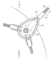
サイドブラシアセンブリー21a,22aは、サイドアーム100と、サイドアーム100の一側端部に回転可能に装着されたブラシユニット110と、で構成される。
The
本体10の前方一側に支持台130が設けられ、支持台130の上部にはアームモーターハウジング140が結合し、支持台130の下部には、サイドアーム100が結合する。
A
アームモーターハウジング140は、アームモーター収容部141を有しており、ここにアームモーター150が収容される。
The arm motor housing 140 has an arm
第1のギア収容部142がアームモーター収容部141とつながって形成されている。第1のギア収容部142には、アームモーター150と結合してサイドアーム100にアームモーター150の駆動力を伝達する第1のギア(図示せず)が収容される。第1のギア収容部142の下端には、第1のギアの中心部に連結された回転軸(図示せず)が突出する。
A first
回転軸(図示せず)は、支持台130の通孔131を貫通して、サイドアーム100の一端に形成された結合溝101に取り付けられる。回転軸が回転すると、サイドアーム100は、結合溝101を基準に回動する。
The rotation shaft (not shown) passes through the through
サイドアーム100には、ブラシモーター120を収容できるブラシモーター収容部103が設けられている。ブラシモーター120の駆動力をブラシユニット110に伝達するための第2のギア(図示せず)を収容する第2のギア収容部102が、ブラシモーター収容部103とつながって形成されている。
The
第2のギア収容部102の下端には、一端が第2のギア(図示せず)の中心部に連結された回転軸の他端が突出する。
At the lower end of the second
突出した回転軸の他端は、ブラシユニット110の回転部111と連結されて、ブラシモーター120の駆動力によって回転部111が回転できるようにする。
The other end of the protruding rotating shaft is connected to the
回転部111から半径方向外側にブラシアーム113が延在する。ブラシアーム113にはブラシ112が結合して、床にあるホコリなどを掃いて本体10の中心部に集める役割を果たす。
A
サイドアーム100の外側には縁カバー104が装着される。縁カバー104は、本体10に形成された開口を覆うと同時に、それ自体が本体10の側面縁の一部を形成する。
An
図3及び図4に示すように、アームモーター150が回転すると、その駆動力は第1のギア(図示せず)を通じてサイドアーム100に伝達され、サイドアーム100が本体10の外側へと回動する。
As shown in FIGS. 3 and 4, when the
サイドアーム100が回動すると、縁カバー104は本体10の開口をそれ以上覆わず、本体10の側面縁を形成しなくなる。
When the
サイドアーム100が結合溝101を中心に回転するので、結合溝101が形成されている部分の反対側の端部に装着されたサイドブラシ110が、本体10の外側に突出する。
Since the
本体10の外側に突出したサイドブラシ110は、掃除できる領域がより広くなり、床の隅や壁と隣接した部分まで掃除可能になる。
The
以下では、ロボット掃除機1aの動作について説明する。 Below, operation | movement of the robot cleaner 1a is demonstrated.
図5に示すように、ロボット掃除機1aの走行方向を基準に右側に壁Wが隣接していると、壁Wに隣接した右側サイドブラシアセンブリー21aが動作する。
As shown in FIG. 5, when the wall W is adjacent to the right side with respect to the traveling direction of the robot cleaner 1a, the right
右側サイドブラシアセンブリー21aのアームモーター150が回転しながらサイドアーム100が結合溝101を中心に回動し、これにより、サイドアーム100が本体10の外側に突出する。
While the
サイドアーム100が本体10の外側に突出すると、サイドアーム100の端部に装着されたサイドブラシ110は、本体10からより遠い所まで掃除可能になる。すなわち、壁Wに接する床にまでサイドブラシ110が達し、よりきれいに掃除することが可能になる。
When the
図6に示すように、ロボット掃除機1aが掃除動作をしながら進行する過程で床の隅Cに接近すると、左側サイドブラシアセンブリー22aも右側サイドブラシアセンブリー21aも動作する。
As shown in FIG. 6, when the robot cleaner 1a advances while performing a cleaning operation, the left
床の隅Cは2つの壁面が接する所に形成されるので、本体10の前方と左側または右側とに壁面が隣接することになる。
Since the corner C of the floor is formed where the two wall surfaces contact each other, the wall surfaces are adjacent to the front side and the left side or the right side of the
本発明によるロボット掃除機は、床の隅の掃除を容易にさせると共に、壁面に隣接した部分の掃除を容易にさせることを目的とする。 An object of the robot cleaner according to the present invention is to facilitate cleaning of a corner of a floor and to easily clean a portion adjacent to a wall surface.
そのため、本体10の前方に壁面が隣接すると、両サイドブラシアセンブリー21a,22aとも動作するようになる。
Therefore, when the wall surface is adjacent to the front of the
そして、ロボット掃除機1aが隅に接近すると、前述したように、本体10の側面及び前方とも壁に隣接するようになるから、2つのサイドブラシアセンブリー21a,22aが動作する。
When the robot cleaner 1a approaches the corner, as described above, both the side surface and the front of the
このように、2つのサイドブラシアセンブリー21a,22aの両方が動作すると、前方壁面に隣接した部分、側方壁面に隣接した部分、及び床の隅を全て効率的に掃除することができる。
As described above, when both the two
サイドブラシアセンブリー21a,22aの動作過程は前述した通りであるから、その説明は省略する。
Since the operation process of the
以下、上記の実施例と重複する構成についての説明は省略するものとする。 Hereinafter, the description of the same configuration as the above embodiment will be omitted.
図7乃至図9に示すように、サイドブラシアセンブリー21b,22bが本体10の前方両側に2つ装着される。
As shown in FIGS. 7 to 9, two
ブラシユニット220が装着されたアームホルダー210には、ガイド本体208とガイドカバー201とが積層されて本体10の一側に装着される。
A guide
アームホルダー210には、3個のブラシユニット220を装着できるブラシ着座口211が、ブラシユニット220の個数と同一に3個形成される。ブラシ着座口211は、アームホルダー210の中心から半径方向外側に延在する。
The
アームホルダー210の中心には、後述するホルダーモーター260の駆動力をアームホルダー210に伝達してアームホルダー210を回転させるホルダー軸212が突設される。
At the center of the
アームホルダー210のブラシ着座口211には、ブラシユニット220が装着される。ブラシユニット220は、ブラシユニット220をアームホルダー210に固定させるブラシアーム221と、ブラシアーム221の内部に一端が収容されてブラシアーム221の外部に延びるブラシ223と、で構成される。
The
ブラシユニット220は、アームホルダー210が回転すると、ブラシ着座口211内でブラシ着座口211に沿って前後に移動する。
When the
ブラシアーム221の上面には、ブラシアーム221を後述するレール203に固定させてブラシアーム221がレール203に沿って一定の軌跡で回動できるようにするガイドフック222が形成される。ガイドフック222は、ブラシアーム221の上面で上方に突設され、その端部がホルダー軸212が存在する中心方向に折り曲がって全体的にフック状になる。
A
ブラシガイド200は、ガイド本体208と、ガイド本体208の上部を覆うガイドカバー201と、で構成される。
The
ガイド本体208には、その内部にアームホルダー210のホルダー軸212が貫通できる第1の通孔205が形成される。また、ガイド本体208には、ガイド本体208の上面縁部に沿って上方に突出して内側リーブ202が設けられる。
The
ガイドカバー201も同様に、その内部にアームホルダー210のホルダー軸212が貫通できる第2の通孔207が形成される。また、ガイドカバー201には、ガイドカバー201の上面縁部に沿って下方に突出して外側リーブ204が形成される。外側リーブ204は、内側リーブ202に比べて、より外縁側に偏って形成される。すなわち、外側リーブ204により形成された内部空間を、内側リーブ202により形成された内部空間よりも大きくしなければならない。
Similarly, a second through
ガイド本体208とガイドカバー201とが結合すると、外側リーブ204及び内側リーブ202に囲まれたレール203が形成され、このレール203にガイドフック222が装着されて回動するようになる。
When the guide
アームホルダー210にブラシガイド200が積層されて本体10の下方から装着されると、ホルダー軸212は、第1の通孔205及び第2の通孔207を貫通し、その端部が本体10の一側下面に隣接して配置される。
When the
ブラシガイド200の一部は本体10の外側に突出するように設けられる。
A part of the
本実施例に係るブラシガイド200の全体的な外形は卵状を有する。すなわち、本体10の内部に位置する部分は、曲率半径が相対的に大きいアーク状に形成され、本体10の外部に位置する部分は、曲率半径が相対的に小さいアーク状に形成される。そのため、ブラシガイド200が円形に形成される場合に比べて、本体10の外部へ行くほどブラシガイド200の一部がより外側に突出するような構造を有する。
The overall outer shape of the
ブラシガイド200が上記のような構造を有するため、ガイド本体208及びガイドカバー201の縁部に沿って形成された内側リーブ202及び外側リーブ204も、上述したブラシガイド200と類似の形状を有する。さらに、内側リーブ202及び外側リーブ204により形成されるレール203も、同様の形状を有する。
Since the
本実施例と異なる形状のブラシガイドであっても、本体10の外側へ行くほどブラシガイド200の一部が本体10の外側へより突出できるものであればいずれも可能である。例えば、角を丸めた三角形や楕円形にしたブラシガイド200も本発明の実施例に含まれる。
Even a brush guide having a shape different from that of the present embodiment can be used as long as a part of the
さらに、円形のブラシガイド200であっても、ホルダー軸212が円の中心から外れた縁部を貫通すると、本体10の外側へ行くほどブラシガイド200の一部が本体10の外側へより突出可能になり、本発明の実施例に含まれる。
Further, even in the case of the
アームホルダー210及びブラシガイド200が装着された部分の上側には、ホルダーモーター260が収容されるホルダーモーターハウジング251が配置される。
A
また、ホルダーモーター260の駆動力をアームホルダー210に伝達するホルダーギア(図示せず)が収容されるホルダーギア収容部252が設けられる。ホルダーギアから延びた回転軸は、本体10の一側に形成された第3の通孔241を貫通してホルダー軸212に連結され、ホルダー軸212及びアームホルダー210を回転させる。
In addition, a holder
ガイドカバー201の一側には、フック状の第1の掛止部231が設けられ、本体10の下面にはフック状の第2の掛止部232が形成される。第1の掛止部231及び第2の掛止部232には弾性部材230が係合する。
A hook-shaped first latching
弾性部材230は、ブラシガイド200の一部を外側に突出させるように付勢する。その動作については、図12を参照して後述する。
The
以下では、サイドブラシアセンブリー21b,22bの動作について説明する。
Below, operation | movement of the
図10及び図11に示すように、アームホルダー210は、ホルダー軸212を中心に元の位置で回転する。一方、ブラシユニット220は、レール203に沿って移動するガイドフック222によりブラシガイド200の形状に沿って回動する。
As shown in FIGS. 10 and 11, the
元の位置に固定されて回転するアームホルダー210と、ブラシガイド200及びレール203の形状に沿って移動するブラシユニット220の移動経路のズレにより、ブラシユニット220はブラシ着座口211で前後に移動する。
The
本体10の外部に突出したブラシガイド200の一部分をブラシユニット220が通る際に、ブラシユニット220はブラシ着座口211内でアームホルダー210の半径方向外側に前進し、よって、ブラシユニット220も本体10の外側に最大限に突出する。逆に、本体10の内側に位置するブラシガイド200の一部分をブラシユニット220が通る際には、ブラシユニット220は、ホルダー軸212が位置しているアームホルダー210の中心部に後進する。
When the
このように簡単な構造を用いてブラシユニット220を本体10の外部へ、より突出させることができる。本体10の外部へより突出したブラシユニット220は、床の隅部や壁面と隣接した部分に積もったホコリを效率的に本体10側に掃き集めることができる。
In this way, the
図12に示すように、ブラシガイド200は、本体10の一側下面に固定されるのではなく、ホルダー軸212を基準に回動可能なように装着されるだけである。ただし、弾性部材によってブラシガイド200の一部が外側に突出する状態を維持することができる。
As shown in FIG. 12, the
このように、ブラシガイド200は弾性部材230により弾性的に回動可能に本体10に装着される。
As described above, the
そのため、本体10の外部に突出したブラシガイド200の一部が障害物に接触しても、ブラシガイド200が回動しながら障害物を避けると同時に、ブラシガイド200の破損を防止することができる。
Therefore, even if a part of the
本体10が前進して障害物を完全に回避すると、弾性部材の弾性力によりブラシガイド200の一部は本体10の外側に再び突出する。
When the
上記の実施例と重複する構成については説明を省略する。 The description of the same configuration as the above embodiment is omitted.
図13及び図14に示すように、サイドブラシアセンブリー21c,22cは、本体10の下面に装着されて回転する回転盤310と、回転盤310に結合して回動するブラシユニット330と、ブラシユニット330の運動をガイドするブラシガイド340と、で構成される。
As shown in FIGS. 13 and 14, the
本体10において回転盤310の装着される部分の上側には、回転盤310を回転させるための回転盤モーター350を収容するモーター収容部320が設けられる。モーター収容部320は、本体において回転盤モーター350の形状に沿って上方に突設され、その内部に、回転盤モーター350が収容される着座口321が形成される。
In the
着座口321に収容された回転盤モーター350の下部には、回転盤モーター350の回転力を回転盤310に伝達するための回転軸351が設けられる。回転軸351の一端は、回転盤モーター350に連結され、他端は、回転盤310の中心部に形成された収容溝312に結合することで、回転盤モーター350の駆動力を回転盤310に伝達する。
A
回転盤310の上面には固定突起311が上方に突設される。固定突起311にはブラシユニット330が固定され、回転盤310の回転によってブラシユニット330が回動する。
A fixed
ブラシユニット330は、ブラシシャフト331と、ブラシシャフト331の一端に取り付けられたブラシ333と、で構成される。ブラシシャフト331の中心部は中空にしてスライディング部332を形成する。
The
ブラシガイド340は、回転盤310に比べて、より本体10の縁部に近接するように装着され、本体10の下部に支持されるための支持部340と、支持部340から突設された突出部341と、で構成される。
The
突出部341は、ブラシユニット330のスライディング部332に挿入されて、ブラシユニット330が扇状の軌跡を描きながら回動できるようにする。
The protruding
以下に、サイドブラシアセンブリー21c,22cの動作について説明する。
Below, operation | movement of the
図15に示すように、ブラシユニット330の一端は、回転盤310に結合して回転運動をするが、ブラシユニット330の中間部分はブラシガイド340の突出部341に固定される。そのため、ブラシユニット330のブラシ333が装着された部分は、扇状の軌跡を描きながら運動をする。
As shown in FIG. 15, one end of the
ブラシユニット330が本体10の外側に最大限に突出した状態で回転盤310が回転すると、ブラシユニット330は点線で表示された状態に回動する。このように回動すると、ブラシユニット330のブラシ333は、本体10から遠くにあるホコリを本体10の後方Rに掃くと同時に、本体10に近い方向に掃くこととなる。
When the
ブラシ333により本体10の近くに導かれたホコリは、メインブラシユニット(図2参照)30及び送風装置(図示せず)により本体10の内部に容易に吸い込まれる。
The dust guided to the vicinity of the
図16は、図15に示す動作後のブラシユニット330の動作を示す図である。
FIG. 16 is a diagram illustrating the operation of the
図16に示すように、回転盤310の回転によってブラシユニット330のブラシ333は後方Rから前方Fへと回動するが、図15と違い、本体10に近接した状態で回動するため、本体10から遠く離れたホコリをさまざまな方向に飛散させることはない。
As shown in FIG. 16, the
一方、本体10に近接したホコリを本体10の前方に掃き出すこともあるが、本体10に近接したホコリは既にメインブラシユニット30(図2参照)及び送風装置(図示せず)により本体10の内部に相当吸い込まれたため、掃除効率への影響は小さい。
On the other hand, dust near the
図15及び図16を踏まえてブラシユニット330のブラシ333の動作を類推すると、全体的に扇状の軌跡を描くこととなる。
By analogizing the operation of the
特に、本体10から遠く離れているホコリを掃き集める際には、常に、本体10の前方Fから後方Rへとホコリを掃く。
In particular, when sweeping away dust that is far from the
このような構造によれば、簡単な構造により、本体10から遠く離れたホコリを掃除できる他、そのホコリを本体10に近接した方向に容易に掃き集められ、掃除効率を高めることができる。
According to such a structure, dust that is far away from the
1a,1b,1c ロボット掃除機
10 本体
21a,22a,21b,22b,21c,22c サイドブラシアセンブリー
1a, 1b,
Claims (26)
前記床の隅を掃除するように前記本体に設けられた少なくとも一つのサイドブラシアセンブリーと、
を備え、
前記サイドブラシアセンブリーは、
前記本体に回動可能に結合され、前記本体の内部に挿入された第1の位置と前記本体の側面縁の外側に突出した第2の位置との間で移動するサイドアームと、
前記床を掃くように前記サイドアームに設けられたブラシユニットと、
前記サイドアームが前記本体の内部に挿入された時に、前記本体の側面縁の一部を形成するように前記サイドアームに結合された縁カバーと、
を有することを特徴とする、ロボット掃除機。 A body configured to remove dust from the floor while traveling on the floor, and having a side edge forming a side appearance of the robot cleaner;
At least one side brush assembly provided on the body to clean a corner of the floor;
With
The side brush assembly is
A side arm that is pivotally coupled to the main body and moves between a first position inserted into the main body and a second position protruding outside a side edge of the main body;
A brush unit provided on the side arm so as to sweep the floor;
An edge cover coupled to the side arm so as to form part of a side edge of the body when the side arm is inserted into the body;
A robot cleaner characterized by comprising:
前記サイドアームの端部に設けられて前記サイドアームを回動させるアームモーターをさらに有することを特徴とする、請求項1に記載のロボット掃除機。 The side brush assembly is
The robot cleaner according to claim 1, further comprising an arm motor that is provided at an end of the side arm and rotates the side arm.
前記サイドアームが回転できるようにし、前記サイドアームの端部に装着された回転部と、
前記回転部から半径方向外側に延在した複数のブラシと、
を有することを特徴とする、請求項1に記載のロボット掃除機。 The brush unit is
Allowing the side arm to rotate, a rotating part mounted on the end of the side arm;
A plurality of brushes extending radially outward from the rotating portion;
The robot cleaner according to claim 1, comprising:
前記回転部を回転させるように前記サイドアームの端部に設けられたブラシモーターをさらに有することを特徴とする、請求項4に記載のロボット掃除機。 The brush unit is
The robot cleaner according to claim 4, further comprising a brush motor provided at an end portion of the side arm so as to rotate the rotating portion.
走行方向を基準に前記本体の両側前面に設けられた複数のサイドブラシアセンブリーと、
を備え、
前記複数のサイドブラシアセンブリーは、
前記本体に回動可能に結合され、前記本体の前記開口を介して前記本体の内部に挿入された位置と前記本体の側面縁の外側に突出した位置との間で移動するサイドアームと、
前記床を掃くように前記サイドアームに設けられたブラシユニットと、
前記サイドアームが前記本体の内部に挿入された位置に移動すると、前記開口を覆うように構成された縁カバーと、
を有することを特徴とする、ロボット掃除機。 A body configured to remove dust from the floor while traveling on the floor, forming a side surface appearance of the robot cleaner, and a body having an opening formed in the side edge;
A plurality of side brush assemblies provided on both front sides of the main body based on the running direction;
With
The plurality of side brush assemblies includes:
A side arm that is pivotally coupled to the main body and moves between a position inserted into the main body through the opening of the main body and a position protruding to the outside of a side edge of the main body;
A brush unit provided on the side arm so as to sweep the floor;
An edge cover configured to cover the opening when the side arm moves to a position inserted into the body;
A robot cleaner characterized by comprising:
前記床の隅を掃除するように前記本体に設けられた少なくとも一つのサイドブラシアセンブリーと、
を備え、
前記サイドブラシアセンブリーは、
ホルダー軸を中心に回転可能に取り付けられたアームホルダーと、
前記ホルダー軸に対して半径方向に沿って移動可能なように前記アームホルダーに結合されたブラシアームと、
前記床を掃くように前記ブラシアームに結合されたブラシと、
前記本体に結合されて前記ブラシアームの移動を案内するブラシガイドであって、前記アームホルダーの回転時に前記ブラシアームが前記本体の外側に突出する方向に移動するように前記ブラシアームを案内するレールを有するブラシガイドと、
を有することを特徴とする、ロボット掃除機。 A body configured to clean the floor while traveling on the floor;
At least one side brush assembly provided on the body to clean a corner of the floor;
With
The side brush assembly is
An arm holder mounted rotatably around the holder axis;
A brush arm coupled to the arm holder so as to be movable in a radial direction with respect to the holder axis;
A brush coupled to the brush arm to sweep the floor;
A brush guide coupled to the main body for guiding the movement of the brush arm, the rail guiding the brush arm so that the brush arm moves in a direction protruding to the outside of the main body when the arm holder rotates. A brush guide having
A robot cleaner characterized by comprising:
前記レールの一部分は、前記本体の側面の外側に突出したことを特徴とする、請求項13に記載のロボット掃除機。 The rail is arranged so as to surround the holder shaft,
The robot cleaner according to claim 13, wherein a part of the rail protrudes outside a side surface of the main body.
前記レールの頂点部は、前記本体の側面から外側に最も突出したことを特徴とする、請求項13に記載のロボット掃除機。 The rail has a vertex farthest from the holder axis;
The robot cleaner according to claim 13, wherein a top portion of the rail protrudes most outward from a side surface of the main body.
前記床の隅を掃除するように前記本体に設けられた少なくとも一つのサイドブラシアセンブリーと、
を備え、
前記サイドブラシアセンブリーは、
ホルダー軸を中心に回転可能に設けられたアームホルダーと、
前記ホルダー軸に対して半径方向に沿って移動可能なように前記アームホルダーに結合されたブラシアームと、
前記床を掃くように前記ブラシアームに結合されたブラシと、
前記アームホルダーの回転時に前記ブラシアームが前記本体の外側に突出する方向に移動するように前記ブラシアームを案内するレールを有するブラシガイドと、
を有し、
前記レールは、前記本体の側面の外側に位置する第1のアーク部と、前記本体の内部に位置する第2のアーク部と、を有し、前記ホルダー軸から前記第1のアーク部までの最長距離は、前記ホルダー軸から前記第2のアーク部までの距離よりも長いことを特徴とする、ロボット掃除機。 A body configured to clean the floor while traveling on the floor;
At least one side brush assembly provided on the body to clean a corner of the floor;
With
The side brush assembly is
An arm holder provided rotatably around the holder axis;
A brush arm coupled to the arm holder so as to be movable in a radial direction with respect to the holder axis;
A brush coupled to the brush arm to sweep the floor;
A brush guide having a rail for guiding the brush arm so that the brush arm moves in a direction protruding to the outside of the main body during rotation of the arm holder;
Have
The rail has a first arc portion located outside the side surface of the main body, and a second arc portion located inside the main body, from the holder shaft to the first arc portion. The longest distance is longer than the distance from the holder shaft to the second arc part.
前記床の隅を掃除するように前記本体に設けられた少なくとも一つのサイドブラシアセンブリーと、
を備え、
前記サイドブラシアセンブリーは、
ホルダー軸を中心に回転可能なように設けられたアームホルダーと、
前記ホルダー軸に対して半径方向に沿って移動可能なように前記アームホルダーに結合されたブラシアームと、
前記床を掃くように前記ブラシアームに結合されたブラシと、
前記アームホルダーの回転時に前記ブラシアームが前記本体の外側に突出する方向に移動するように前記ブラシアームを案内するレールを有するブラシガイドと、
を有し、
前記レールは、前記本体の側面の外側に位置する第1のアーク部と、前記本体の内部に位置する第2のアーク部と、を有し、前記第1のアーク部の曲率半径は、前記第2のアーク部の曲率半径よりも小さいことを特徴とする、ロボット掃除機。 A body configured to clean the floor while traveling on the floor;
At least one side brush assembly provided on the body to clean a corner of the floor;
With
The side brush assembly is
An arm holder provided so as to be rotatable about the holder axis;
A brush arm coupled to the arm holder so as to be movable in a radial direction with respect to the holder axis;
A brush coupled to the brush arm to sweep the floor;
A brush guide having a rail for guiding the brush arm so that the brush arm moves in a direction protruding to the outside of the main body during rotation of the arm holder;
Have
The rail has a first arc portion located outside the side surface of the main body, and a second arc portion located inside the main body, and the radius of curvature of the first arc portion is A robot cleaner characterized by being smaller than the radius of curvature of the second arc part.
前記床の隅を掃除するように前記本体に設けられた少なくとも一つのサイドブラシアセンブリーと、
を備え、
前記サイドブラシアセンブリーは、
前記本体に装着されて回転する回転盤と、
一端部が前記回転盤に結合して回動しながらホコリを掃くブラシユニットと、
前記ブラシユニットの運動をガイドするために前記本体に装着されたブラシガイドと、
を有し、
前記ブラシユニットは、前記ブラシガイドに対してスライディング運動をしながら扇状の軌跡で運動することを特徴とする、ロボット掃除機。 A body configured to clean the floor while traveling on the floor;
At least one side brush assembly provided on the body to clean a corner of the floor;
With
The side brush assembly is
A turntable mounted on the main body and rotating;
A brush unit that sweeps dust while one end is coupled to the rotating disk and rotates;
A brush guide mounted on the main body to guide the movement of the brush unit;
Have
The robot cleaner according to claim 1, wherein the brush unit moves in a fan-shaped locus while performing a sliding motion with respect to the brush guide.
前記ブラシユニットは、その内部に前記突出部が挿入されて前記ブラシユニットがスライディング運動できるようにするスライディング部を有することを特徴とする、請求項23に記載のロボット掃除機。 The brush guide has a support part that supports the brush guide, and a protrusion part that protrudes from the support part and guides the movement of the brush unit,
The robot cleaner according to claim 23, wherein the brush unit has a sliding part into which the protruding part is inserted to allow the brush unit to perform a sliding motion.
Applications Claiming Priority (2)
| Application Number | Priority Date | Filing Date | Title |
|---|---|---|---|
| KR1020110101852A KR101907161B1 (en) | 2011-10-06 | 2011-10-06 | Robot cleaner |
| KR10-2011-0101852 | 2011-10-06 |
Publications (1)
| Publication Number | Publication Date |
|---|---|
| JP2013081775A true JP2013081775A (en) | 2013-05-09 |
Family
ID=47172283
Family Applications (1)
| Application Number | Title | Priority Date | Filing Date |
|---|---|---|---|
| JP2012223600A Pending JP2013081775A (en) | 2011-10-06 | 2012-10-05 | Robot cleaner |
Country Status (7)
| Country | Link |
|---|---|
| US (2) | US9078552B2 (en) |
| EP (3) | EP2578127B1 (en) |
| JP (1) | JP2013081775A (en) |
| KR (1) | KR101907161B1 (en) |
| CN (2) | CN103027634B (en) |
| AU (1) | AU2012319325B2 (en) |
| WO (1) | WO2013051843A1 (en) |
Cited By (10)
| Publication number | Priority date | Publication date | Assignee | Title |
|---|---|---|---|---|
| JP2014236803A (en) * | 2013-06-06 | 2014-12-18 | シャープ株式会社 | Support structure of revolving shaft for auxiliary brush and self-propelled vacuum cleaner including the same |
| JP2015091290A (en) * | 2013-10-04 | 2015-05-14 | 株式会社コーワ | Side brush for cleaner and self-propelled cleaner |
| WO2015163372A1 (en) * | 2014-04-22 | 2015-10-29 | 株式会社東芝 | Electric cleaner |
| WO2015163373A1 (en) * | 2014-04-22 | 2015-10-29 | 株式会社東芝 | Electric cleaner |
| JP2016052472A (en) * | 2014-09-04 | 2016-04-14 | 株式会社マキタ | Self-propelled dust collection robot |
| JP2016153058A (en) * | 2016-06-02 | 2016-08-25 | 日立アプライアンス株式会社 | Autonomous travel type cleaner |
| JP2017100038A (en) * | 2017-03-10 | 2017-06-08 | シャープ株式会社 | Support structure for rotating shaft for auxiliary brush and self-propelled vacuum cleaner provided with the same |
| JP2018149360A (en) * | 2018-05-31 | 2018-09-27 | 日立アプライアンス株式会社 | Autonomous traveling type cleaner |
| JP2019027595A (en) * | 2017-07-26 | 2019-02-21 | 日本電産株式会社 | Gear unit, speed reduction device and cleaning robot |
| JP2020520683A (en) * | 2017-05-25 | 2020-07-16 | アイロボット・コーポレーション | Brush for autonomous cleaning robot |
Families Citing this family (127)
| Publication number | Priority date | Publication date | Assignee | Title |
|---|---|---|---|---|
| US9357897B2 (en) * | 2009-02-28 | 2016-06-07 | Brent McNair Estep | Hands-free pot scrubber |
| KR101907161B1 (en) * | 2011-10-06 | 2018-10-15 | 삼성전자주식회사 | Robot cleaner |
| US20130092190A1 (en) * | 2011-10-18 | 2013-04-18 | Samsung Electronics Co., Ltd. | Robot cleaner and control method for the same |
| ES2610755T3 (en) | 2012-08-27 | 2017-05-03 | Aktiebolaget Electrolux | Robot positioning system |
| USD718008S1 (en) * | 2012-08-28 | 2014-11-18 | Samsung Electronics Co., Ltd. | Vacuum cleaner |
| AU349620S (en) * | 2012-09-24 | 2013-07-04 | Dyson Technology Ltd | A vacuum cleaner |
| AU349618S (en) * | 2012-09-24 | 2013-07-04 | Dyson Technology Ltd | A vacuum cleaner |
| AU349619S (en) * | 2012-09-24 | 2013-07-04 | Dyson Technology Ltd | A vacuum cleaner |
| KR102021894B1 (en) * | 2012-10-18 | 2019-11-04 | 엘지전자 주식회사 | Method of controlling an automatic cleaner |
| USD720510S1 (en) * | 2012-11-13 | 2014-12-30 | Lg Electronics Inc. | Robot vacuum cleaner |
| USD720511S1 (en) * | 2012-11-13 | 2014-12-30 | Lg Electronics Inc. | Robot vacuum cleaner |
| TWD161487S (en) * | 2013-02-07 | 2014-07-01 | 聯潤科技股份有限公司 | Part of the self-propelled cleaning device |
| USD714003S1 (en) * | 2013-03-15 | 2014-09-23 | Carl Freudenberg Kg | Robotic vacuum |
| USD714002S1 (en) * | 2013-03-15 | 2014-09-23 | Carl Freudenberg Kg | Robotic vacuum |
| USD720103S1 (en) * | 2013-03-20 | 2014-12-23 | Vorwerk & Co. Interholding Gmbh | Cleaning robot |
| WO2014169943A1 (en) * | 2013-04-15 | 2014-10-23 | Aktiebolaget Electrolux | Robotic vacuum cleaner |
| CN105101855A (en) * | 2013-04-15 | 2015-11-25 | 伊莱克斯公司 | Robotic vacuum cleaner with sticking out side brushes |
| KR101494804B1 (en) * | 2013-04-19 | 2015-02-23 | 주식회사 유진로봇 | Suction Type Cleaning Robot |
| WO2015037755A1 (en) * | 2013-09-12 | 2015-03-19 | 엘지전자 주식회사 | Automatic cleaner |
| CN103584804B (en) * | 2013-11-21 | 2017-02-08 | 中山市金舜家庭用品有限公司 | Automatic ground cleaner |
| CN105792721B (en) | 2013-12-19 | 2020-07-21 | 伊莱克斯公司 | Robotic vacuum cleaner with side brush moving in spiral pattern |
| JP6638987B2 (en) * | 2013-12-19 | 2020-02-05 | アクチエボラゲット エレクトロルックス | Adaptive speed control of rotating side brush |
| US9946263B2 (en) | 2013-12-19 | 2018-04-17 | Aktiebolaget Electrolux | Prioritizing cleaning areas |
| EP3084540B1 (en) | 2013-12-19 | 2021-04-14 | Aktiebolaget Electrolux | Robotic cleaning device and operating method |
| CN105829985B (en) | 2013-12-19 | 2020-04-07 | 伊莱克斯公司 | Robot cleaning device with peripheral recording function |
| KR102137857B1 (en) | 2013-12-19 | 2020-07-24 | 에이비 엘렉트로룩스 | Robotic cleaning device and method for landmark recognition |
| JP6494118B2 (en) | 2013-12-19 | 2019-04-03 | アクチエボラゲット エレクトロルックス | Control method of robot cleaner associated with detection of obstacle climbing, and robot cleaner, program, and computer product having the method |
| US10231591B2 (en) | 2013-12-20 | 2019-03-19 | Aktiebolaget Electrolux | Dust container |
| DE102014100006A1 (en) * | 2014-01-02 | 2015-07-02 | Miele & Cie. Kg | robotic vacuum |
| DE102014100013A1 (en) * | 2014-01-02 | 2015-07-02 | Miele & Cie. Kg | Autonomous tillage implement |
| DE102014100162A1 (en) * | 2014-01-09 | 2015-07-09 | Miele & Cie. Kg | Self-propelled cleaning device and operating method for a self-propelled cleaning device |
| DE102014101390A1 (en) | 2014-02-05 | 2015-08-06 | Miele & Cie. Kg | robotic vacuum |
| KR102137524B1 (en) * | 2014-02-13 | 2020-07-24 | 삼성전자주식회사 | Robot cleaner |
| CN106455883B (en) | 2014-05-08 | 2020-03-06 | 阿尔弗雷德·卡赫欧洲两合公司 | Self-propelled and self-steering floor cleaning device and method for cleaning a floor |
| DE102015101587B3 (en) * | 2014-05-30 | 2015-07-09 | Wessel-Werk Gmbh | Robotsauger with multiple arrangement of side brushes |
| WO2016002186A1 (en) * | 2014-06-30 | 2016-01-07 | パナソニックIpマネジメント株式会社 | Autonomous travel-type cleaner |
| CN106415423B (en) | 2014-07-10 | 2021-01-01 | 伊莱克斯公司 | Method for detecting measurement errors of robotic cleaning devices |
| AU360831S (en) | 2014-08-28 | 2015-03-30 | Dyson Technology Ltd | Vacuum cleaner |
| AU360829S (en) | 2014-08-28 | 2015-03-30 | Dyson Technology Ltd | Vacuum cleaner |
| AU360979S (en) | 2014-08-28 | 2015-04-08 | Dyson Technology Ltd | Vacuum cleaner |
| AU360807S (en) | 2014-08-28 | 2015-03-26 | Dyson Technology Ltd | Vacuum cleaner |
| AU360824S (en) | 2014-08-28 | 2015-03-30 | Dyson Technology Ltd | Vacuum cleaner |
| AU360825S (en) | 2014-08-28 | 2015-03-30 | Dyson Technology Ltd | Vacuum cleaner |
| AU360827S (en) | 2014-08-28 | 2015-03-30 | Dyson Technology Ltd | Vacuum cleaner |
| KR102271785B1 (en) | 2014-09-08 | 2021-06-30 | 에이비 엘렉트로룩스 | Robotic vacuum cleaner |
| CN106659344B (en) | 2014-09-08 | 2019-10-25 | 伊莱克斯公司 | robot vacuum cleaner |
| DE102014118126A1 (en) | 2014-12-08 | 2016-06-09 | Miele & Cie. Kg | Vacuum robot with at least one side arm |
| US10877484B2 (en) | 2014-12-10 | 2020-12-29 | Aktiebolaget Electrolux | Using laser sensor for floor type detection |
| CN107072454A (en) * | 2014-12-12 | 2017-08-18 | 伊莱克斯公司 | Side brushes and robot vacuums |
| KR102326401B1 (en) | 2014-12-16 | 2021-11-16 | 에이비 엘렉트로룩스 | Cleaning method for a robotic cleaning device |
| US10534367B2 (en) | 2014-12-16 | 2020-01-14 | Aktiebolaget Electrolux | Experience-based roadmap for a robotic cleaning device |
| US9757004B2 (en) * | 2015-02-12 | 2017-09-12 | Irobot Corporation | Liquid management for floor-traversing robots |
| KR102343513B1 (en) | 2015-04-17 | 2021-12-28 | 에이비 엘렉트로룩스 | Robot cleaning device and control method of robot cleaning device |
| DE102015108823A1 (en) | 2015-06-03 | 2016-12-08 | Miele & Cie. Kg | Cleaning device for a self-propelled soil cultivation device |
| CN107920709A (en) | 2015-09-03 | 2018-04-17 | 伊莱克斯公司 | Robotic cleaning device system |
| KR101692737B1 (en) * | 2015-09-23 | 2017-01-04 | 엘지전자 주식회사 | Robot Cleaner |
| CN105534432A (en) * | 2016-01-14 | 2016-05-04 | 丁明伟 | Oil dirt removing device |
| WO2017157421A1 (en) | 2016-03-15 | 2017-09-21 | Aktiebolaget Electrolux | Robotic cleaning device and a method at the robotic cleaning device of performing cliff detection |
| CN105982621B (en) | 2016-04-14 | 2019-12-13 | 北京小米移动软件有限公司 | Air duct structure of automatic cleaning equipment and automatic cleaning equipment |
| US11122953B2 (en) | 2016-05-11 | 2021-09-21 | Aktiebolaget Electrolux | Robotic cleaning device |
| DE102016111811A1 (en) * | 2016-06-28 | 2017-12-28 | Vorwerk & Co. Interholding Gmbh | Wet cleaning device with a cleaning roller |
| CN107788900B (en) * | 2016-08-30 | 2024-08-30 | 科沃斯机器人股份有限公司 | Cleaning robot |
| EP3335610B1 (en) | 2016-12-14 | 2024-03-06 | Advanced Digital Broadcast S.A. | A surface processing device and a method for processing surface areas |
| CN114468875A (en) * | 2016-12-16 | 2022-05-13 | 云鲸智能科技(东莞)有限公司 | Cleaning robot and cleaning robot system |
| USD856682S1 (en) * | 2017-02-08 | 2019-08-20 | AI Incorporated | Circular brush |
| CN109898454B (en) * | 2017-03-06 | 2020-11-06 | 杭州富阳新堰纸制品有限公司 | A robot for municipal works |
| US11284702B2 (en) | 2017-05-15 | 2022-03-29 | Sharkninja Operating Llc | Side brush with bristles at different lengths and/or angles for use in a robot cleaner and side brush deflectors |
| CN110621208A (en) | 2017-06-02 | 2019-12-27 | 伊莱克斯公司 | Method for detecting a height difference of a surface in front of a robotic cleaning device |
| US10980385B1 (en) | 2017-08-11 | 2021-04-20 | AI Incorporated | Oscillating side brush for mobile robotic vacuum |
| US10898042B2 (en) | 2017-08-16 | 2021-01-26 | Sharkninja Operating Llc | Robotic vacuum |
| DE102017119216A1 (en) * | 2017-08-22 | 2019-02-28 | Vorwerk & Co. Interholding Gmbh | Sweeping brush for a self-propelled cleaning device |
| CN111163671B (en) | 2017-09-07 | 2022-08-23 | 尚科宁家运营有限公司 | Robot cleaner |
| EP3687357B1 (en) | 2017-09-26 | 2024-07-10 | Aktiebolaget Electrolux | Controlling movement of a robotic cleaning device |
| CN107550404A (en) * | 2017-10-26 | 2018-01-09 | 绵阳鑫阳知识产权运营有限公司 | The movement that corner dust can be removed is swept the floor equipment |
| TWI684427B (en) | 2018-01-12 | 2020-02-11 | 聯潤科技股份有限公司 | Self-propelled cleaning device and cleaning method |
| CN108272387A (en) * | 2018-02-07 | 2018-07-13 | 江苏美的清洁电器股份有限公司 | Scrubbing brush and dust catcher |
| US20210228035A1 (en) | 2018-05-18 | 2021-07-29 | Aktiebolaget Electrolux | Robotic cleaning device with retractable side brush |
| CN108784535A (en) * | 2018-06-13 | 2018-11-13 | 芜湖金智王机械设备有限公司 | A kind of sweeper |
| CN108742322A (en) * | 2018-07-27 | 2018-11-06 | 四川大学 | A kind of corner cleaning mechanism |
| CN108968795A (en) * | 2018-08-01 | 2018-12-11 | 佛山市高明曦逻科技有限公司 | Rotary dust catcher with high-freedom degree |
| KR20210035280A (en) | 2018-08-01 | 2021-03-31 | 샤크닌자 오퍼레이팅 엘엘씨 | Robot vacuum cleaner |
| CN210931187U (en) * | 2018-11-19 | 2020-07-07 | 上海楠木机器人科技有限公司 | Side brush telescopic system for cleaning robot |
| CN109645899A (en) * | 2019-01-15 | 2019-04-19 | 广州贤智科技有限公司 | A kind of sweeping robot that the practicability with climbing function is high |
| USD936719S1 (en) * | 2019-02-20 | 2021-11-23 | Lg Electronics Inc. | Home hub robot |
| UA41383S (en) * | 2019-03-18 | 2020-04-27 | Бейцзін Сяомі Мо | CLEANING DEVICE |
| CN110403530B (en) * | 2019-07-02 | 2021-03-23 | 重庆邮电大学 | Swing arm sweeping robot |
| KR20210010188A (en) | 2019-07-19 | 2021-01-27 | 엘지전자 주식회사 | robot cleaner |
| WO2021016024A1 (en) | 2019-07-19 | 2021-01-28 | Techtronic Cordless Gp | Floor cleaner |
| USD940771S1 (en) * | 2019-08-15 | 2022-01-11 | Beijing Xiaomi Mobile Software Co., Ltd. | Robot vacuum cleaner |
| CN110547733B (en) * | 2019-09-18 | 2023-08-11 | 北京小狗吸尘器集团股份有限公司 | Side brush assembly, cleaning robot and moving method of cleaning robot |
| CN110897544A (en) * | 2019-12-13 | 2020-03-24 | 叶先祥 | Window cleaning robot |
| USD952719S1 (en) * | 2020-06-10 | 2022-05-24 | Irobot Corporation | Cover for a programmable robot |
| USD952720S1 (en) * | 2020-06-10 | 2022-05-24 | Irobot Corporation | Buttons for a programmable robot |
| CN111839364B (en) * | 2020-07-21 | 2022-01-18 | 苏州高之仙自动化科技有限公司 | Cleaning assembly and cleaning robot |
| CN111759234A (en) * | 2020-08-04 | 2020-10-13 | 湖南炬神电子有限公司 | A spiral involute side brush assembly and sweeping equipment |
| USD945098S1 (en) * | 2020-08-12 | 2022-03-01 | Irobot Corporation | Cover for a mobile cleaning robot |
| US20220125265A1 (en) * | 2020-10-26 | 2022-04-28 | Guangzhou Thirty Seven Degree Smarthome Co., Ltd. | Intelligent vacuum device with extendable and deformable suction arm |
| WO2022117105A1 (en) * | 2020-12-04 | 2022-06-09 | 苏州宝时得电动工具有限公司 | Cleaning robot |
| CN112716374A (en) * | 2020-12-23 | 2021-04-30 | 深圳市银星智能科技股份有限公司 | Side-sweeping assembly and cleaning robot |
| GB2610793B (en) | 2021-01-22 | 2023-09-13 | Dyson Technology Ltd | Autonomous surface treatment apparatus |
| GB2612567B (en) | 2021-01-22 | 2023-11-22 | Dyson Technology Ltd | Autonomous surface treatment apparatus |
| CN112790685A (en) * | 2021-02-10 | 2021-05-14 | 深圳市杉川机器人有限公司 | Floor cleaning machine |
| CN113069045A (en) * | 2021-03-29 | 2021-07-06 | 广东创意双星科技股份有限公司 | Sweeping and mopping integrated household cleaning robot |
| CN113100667A (en) * | 2021-04-02 | 2021-07-13 | 深圳乐居智能电子有限公司 | Remove cleaning device's limit brush and remove cleaning device |
| CN113545707A (en) * | 2021-08-23 | 2021-10-26 | 广州俊德信息科技有限公司 | Cleaning robot with multiple dust suction ports |
| CN114343496B (en) * | 2021-12-31 | 2023-06-20 | 深圳市杉川机器人有限公司 | Automatic replacement system and automatic replacement method |
| USD1045304S1 (en) * | 2022-02-17 | 2024-10-01 | Ningbo Borine Electric Appliance Co., Ltd. | Sweeping robot |
| EP4260757A1 (en) * | 2022-04-14 | 2023-10-18 | Vorwerk & Co. Interholding GmbH | Cleaning device, sweeping brush for a cleaning device and method for operating a cleaning device |
| EP4260758A1 (en) * | 2022-04-14 | 2023-10-18 | Vorwerk & Co. Interholding GmbH | Cleaning device and sweeping brush for a cleaning device |
| KR20230155899A (en) | 2022-05-04 | 2023-11-13 | 삼성전자주식회사 | Driving Robot apparatus, controlling method thereof, and recording medium for recording program |
| KR20230155898A (en) * | 2022-05-04 | 2023-11-13 | 삼성전자주식회사 | Driving Robot apparatus, controlling method thereof, and recording medium for recording program |
| CN115316889B (en) * | 2022-07-11 | 2023-09-12 | 北京石头世纪科技股份有限公司 | Automatic cleaning equipment |
| CN116269050B (en) * | 2023-03-24 | 2024-02-13 | 麦岩智能科技(北京)有限公司 | Welt cleaning device, cleaning robot and control method |
| WO2025055451A1 (en) * | 2023-09-14 | 2025-03-20 | 科沃斯机器人股份有限公司 | Cleaning robot |
| USD1092884S1 (en) * | 2023-09-14 | 2025-09-09 | Zhongshan Union Optech Research Institute Co., Ltd. | Robot vacuum cleaner |
| DE102023212252A1 (en) * | 2023-12-05 | 2025-06-05 | BSH Hausgeräte GmbH | Side brush and cleaning robot with a side brush |
| JP1788890S (en) * | 2023-12-15 | 2025-01-15 | Cleaning robot body | |
| WO2025139435A1 (en) * | 2023-12-29 | 2025-07-03 | 深圳市杉川机器人有限公司 | Cleaning device |
| USD1085596S1 (en) * | 2024-01-04 | 2025-07-22 | Samsung Electronics Co., Ltd. | Robot cleaner |
| CN117958658A (en) * | 2024-01-05 | 2024-05-03 | 北京石头世纪科技股份有限公司 | cleaning equipment |
| JP1799639S (en) * | 2024-03-06 | 2025-05-27 | Cleaning robot | |
| USD1109963S1 (en) | 2024-03-06 | 2026-01-20 | Beijing Roborock Technology Co., Ltd. | Cleaning robot |
| CA233736S (en) * | 2024-03-06 | 2025-07-09 | Beijing Roborock Technology Co Ltd | Button area of cleaning robot |
| USD1106625S1 (en) * | 2024-06-21 | 2025-12-16 | Aktiebolaget Electrolux | Robotic vacuum cleaner |
| WO2026016946A1 (en) * | 2024-07-15 | 2026-01-22 | 云鲸智能创新(深圳)有限公司 | Side brush, cleaning apparatus and cleaning system |
| USD1093788S1 (en) * | 2025-03-14 | 2025-09-16 | Shenzhen Xuhongchuang Technology Co., Ltd | Robotic vacuum cleaner |
| USD1093787S1 (en) * | 2025-03-14 | 2025-09-16 | Shenzhen Xuhongchuang Technology Co., Ltd | Robotic vacuum cleaner |
Family Cites Families (15)
| Publication number | Priority date | Publication date | Assignee | Title |
|---|---|---|---|---|
| US7571511B2 (en) | 2002-01-03 | 2009-08-11 | Irobot Corporation | Autonomous floor-cleaning robot |
| CN2479913Y (en) * | 2001-06-08 | 2002-03-06 | 刘长庆 | Multi-purpose dust remover |
| JP4097264B2 (en) * | 2003-06-18 | 2008-06-11 | 株式会社東芝 | Electric vacuum cleaner |
| KR100507928B1 (en) * | 2003-07-24 | 2005-08-17 | 삼성광주전자 주식회사 | Robot cleaner |
| JP4201747B2 (en) | 2004-07-29 | 2008-12-24 | 三洋電機株式会社 | Self-propelled vacuum cleaner |
| JP2006296684A (en) * | 2005-04-19 | 2006-11-02 | Funai Electric Co Ltd | Self-propelled vacuum cleaner and vacuum cleaner |
| EP2816434A3 (en) * | 2005-12-02 | 2015-01-28 | iRobot Corporation | Autonomous coverage robot |
| KR20070107956A (en) * | 2006-05-04 | 2007-11-08 | 삼성전자주식회사 | robotic vacuum |
| EP2644074A1 (en) | 2007-05-09 | 2013-10-02 | iRobot Corporation | Robot wall detection system |
| KR101249864B1 (en) | 2007-10-01 | 2013-04-02 | 삼성전자주식회사 | Robot cleaner |
| JP5243879B2 (en) * | 2008-08-04 | 2013-07-24 | 富士重工業株式会社 | Side brush support device for cleaning robot |
| EP2417892B1 (en) * | 2009-06-30 | 2016-06-08 | LG Electronics Inc. | Robot cleaner |
| JP5512225B2 (en) * | 2009-07-31 | 2014-06-04 | Cyberdyne株式会社 | Self-propelled cleaning robot with side brush device |
| KR101667716B1 (en) | 2010-04-01 | 2016-10-19 | 엘지전자 주식회사 | Robot cleaner |
| KR101907161B1 (en) * | 2011-10-06 | 2018-10-15 | 삼성전자주식회사 | Robot cleaner |
-
2011
- 2011-10-06 KR KR1020110101852A patent/KR101907161B1/en not_active Expired - Fee Related
-
2012
- 2012-09-27 US US13/628,915 patent/US9078552B2/en active Active
- 2012-10-04 AU AU2012319325A patent/AU2012319325B2/en not_active Ceased
- 2012-10-04 WO PCT/KR2012/008008 patent/WO2013051843A1/en not_active Ceased
- 2012-10-05 JP JP2012223600A patent/JP2013081775A/en active Pending
- 2012-10-05 EP EP12187470.5A patent/EP2578127B1/en not_active Not-in-force
- 2012-10-05 EP EP12187406.9A patent/EP2578125B1/en not_active Not-in-force
- 2012-10-05 EP EP12187469.7A patent/EP2578126A1/en not_active Withdrawn
- 2012-10-08 CN CN201210377947.5A patent/CN103027634B/en not_active Expired - Fee Related
- 2012-10-08 CN CN201611076350.1A patent/CN106419729B/en not_active Expired - Fee Related
-
2015
- 2015-06-05 US US14/731,609 patent/US9854954B2/en active Active
Cited By (18)
| Publication number | Priority date | Publication date | Assignee | Title |
|---|---|---|---|---|
| JP2014236803A (en) * | 2013-06-06 | 2014-12-18 | シャープ株式会社 | Support structure of revolving shaft for auxiliary brush and self-propelled vacuum cleaner including the same |
| JP2015091290A (en) * | 2013-10-04 | 2015-05-14 | 株式会社コーワ | Side brush for cleaner and self-propelled cleaner |
| KR101892652B1 (en) | 2014-04-22 | 2018-08-28 | 도시바 라이프스타일 가부시키가이샤 | Electric cleaner |
| WO2015163372A1 (en) * | 2014-04-22 | 2015-10-29 | 株式会社東芝 | Electric cleaner |
| WO2015163373A1 (en) * | 2014-04-22 | 2015-10-29 | 株式会社東芝 | Electric cleaner |
| JP2015205089A (en) * | 2014-04-22 | 2015-11-19 | 株式会社東芝 | Electric vacuum cleaner |
| JP2015205090A (en) * | 2014-04-22 | 2015-11-19 | 株式会社東芝 | vacuum cleaner |
| KR20160054566A (en) * | 2014-04-22 | 2016-05-16 | 가부시끼가이샤 도시바 | Electric cleaner |
| US10264938B2 (en) | 2014-04-22 | 2019-04-23 | Toshiba Lifestyle Products & Services Corporation | Vacuum cleaner |
| US9931012B2 (en) | 2014-04-22 | 2018-04-03 | Toshiba Lifestyle Products & Services Corporation | Vacuum cleaner |
| JP2016052472A (en) * | 2014-09-04 | 2016-04-14 | 株式会社マキタ | Self-propelled dust collection robot |
| JP2016153058A (en) * | 2016-06-02 | 2016-08-25 | 日立アプライアンス株式会社 | Autonomous travel type cleaner |
| JP2017100038A (en) * | 2017-03-10 | 2017-06-08 | シャープ株式会社 | Support structure for rotating shaft for auxiliary brush and self-propelled vacuum cleaner provided with the same |
| JP2020520683A (en) * | 2017-05-25 | 2020-07-16 | アイロボット・コーポレーション | Brush for autonomous cleaning robot |
| JP7044713B2 (en) | 2017-05-25 | 2022-03-30 | アイロボット・コーポレーション | Brush for autonomous cleaning robot |
| US12239280B2 (en) | 2017-05-25 | 2025-03-04 | Irobot Corporation | Brush for autonomous cleaning robot |
| JP2019027595A (en) * | 2017-07-26 | 2019-02-21 | 日本電産株式会社 | Gear unit, speed reduction device and cleaning robot |
| JP2018149360A (en) * | 2018-05-31 | 2018-09-27 | 日立アプライアンス株式会社 | Autonomous traveling type cleaner |
Also Published As
| Publication number | Publication date |
|---|---|
| EP2578125B1 (en) | 2015-01-28 |
| EP2578127B1 (en) | 2014-07-16 |
| CN103027634A (en) | 2013-04-10 |
| US9854954B2 (en) | 2018-01-02 |
| WO2013051843A1 (en) | 2013-04-11 |
| CN103027634B (en) | 2017-05-03 |
| AU2012319325A1 (en) | 2014-04-24 |
| EP2578126A1 (en) | 2013-04-10 |
| KR20130037448A (en) | 2013-04-16 |
| US20150265122A1 (en) | 2015-09-24 |
| AU2012319325B2 (en) | 2016-04-14 |
| US9078552B2 (en) | 2015-07-14 |
| US20130086760A1 (en) | 2013-04-11 |
| CN106419729B (en) | 2019-10-18 |
| EP2578125A1 (en) | 2013-04-10 |
| CN106419729A (en) | 2017-02-22 |
| EP2578127A1 (en) | 2013-04-10 |
| KR101907161B1 (en) | 2018-10-15 |
Similar Documents
| Publication | Publication Date | Title |
|---|---|---|
| JP2013081775A (en) | Robot cleaner | |
| JP6706770B2 (en) | Autonomous traveling vacuum cleaner | |
| CN103027633B (en) | Robot cleaner | |
| KR101960816B1 (en) | Cleaning system | |
| JP2013089256A (en) | Robot cleaner and method for controlling the same | |
| US20250089959A1 (en) | Brush for autonomous cleaning robot | |
| JP2003038402A (en) | Cleaning equipment | |
| JP2012228619A (en) | Robot vacuum cleaner | |
| KR20090033608A (en) | robotic vacuum | |
| CN109662657A (en) | Base station and docking method | |
| JP5968100B2 (en) | Self-propelled vacuum cleaner | |
| KR101322589B1 (en) | Automatic cleaner | |
| KR101352170B1 (en) | Mobile robot cleaner | |
| JP2022067662A (en) | Autonomous travel type cleaner | |
| KR101306483B1 (en) | Automatic cleaner | |
| KR100619727B1 (en) | Robot Cleaner Driving Device | |
| CN103402412A (en) | Automatic vacuum cleaner |
Legal Events
| Date | Code | Title | Description |
|---|---|---|---|
| RD04 | Notification of resignation of power of attorney |
Free format text: JAPANESE INTERMEDIATE CODE: A7424 Effective date: 20141226 |