JP2013009482A - Electricity distribution system - Google Patents
Electricity distribution system Download PDFInfo
- Publication number
- JP2013009482A JP2013009482A JP2011139312A JP2011139312A JP2013009482A JP 2013009482 A JP2013009482 A JP 2013009482A JP 2011139312 A JP2011139312 A JP 2011139312A JP 2011139312 A JP2011139312 A JP 2011139312A JP 2013009482 A JP2013009482 A JP 2013009482A
- Authority
- JP
- Japan
- Prior art keywords
- power
- unit
- distribution system
- power distribution
- leakage detection
- Prior art date
- Legal status (The legal status is an assumption and is not a legal conclusion. Google has not performed a legal analysis and makes no representation as to the accuracy of the status listed.)
- Granted
Links
- 230000005611 electricity Effects 0.000 title 1
- 238000001514 detection method Methods 0.000 claims abstract description 162
- 238000006243 chemical reaction Methods 0.000 claims abstract description 26
- 238000009413 insulation Methods 0.000 claims abstract description 16
- 230000007935 neutral effect Effects 0.000 claims abstract description 14
- 238000000926 separation method Methods 0.000 claims description 3
- 208000003663 ventricular fibrillation Diseases 0.000 claims description 3
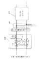
- 238000010586 diagram Methods 0.000 description 23
- 239000000446 fuel Substances 0.000 description 18
- 238000010248 power generation Methods 0.000 description 12
- 238000012986 modification Methods 0.000 description 6
- 230000004048 modification Effects 0.000 description 6
- 238000011144 upstream manufacturing Methods 0.000 description 6
- 230000005856 abnormality Effects 0.000 description 5
- 230000000694 effects Effects 0.000 description 5
- 238000007599 discharging Methods 0.000 description 3
- 230000006870 function Effects 0.000 description 3
- 230000010354 integration Effects 0.000 description 3
- 230000002159 abnormal effect Effects 0.000 description 2
- 238000004891 communication Methods 0.000 description 2
- 230000010365 information processing Effects 0.000 description 2
- 238000009434 installation Methods 0.000 description 2
- 239000004973 liquid crystal related substance Substances 0.000 description 2
- 238000012423 maintenance Methods 0.000 description 2
- 230000001360 synchronised effect Effects 0.000 description 2
- 238000010276 construction Methods 0.000 description 1
- 230000006866 deterioration Effects 0.000 description 1
- 230000008571 general function Effects 0.000 description 1
- 238000005259 measurement Methods 0.000 description 1
- 238000000034 method Methods 0.000 description 1
- 230000002265 prevention Effects 0.000 description 1
Images


Landscapes
- Emergency Protection Circuit Devices (AREA)
- Supply And Distribution Of Alternating Current (AREA)
Abstract
【課題】直流電力源からの直流電力と交流電力源からの交流電力とを用いて安全に電力供給し、システムの大型化を招くことなく、漏電検出を確実にする。
【解決手段】配電システムは、中性線接地された単相3線の給電路を有し、交流電力源からの交流電力を給電路に配電する交流配電部と、直流電力源からの直流電力を配電する直流配電部と、を含む。交流配電部は、中性線接地を基準電位として、交流電力の給電路における漏洩電流を検出する第1の漏電検出部を有する。直流配電部は、直流を交流に変換する絶縁式の直流−交流変換部と、直流−交流変換部に接続され、直流電力の給電路の中点電位点に接地部を有する中点接地部と、直流−交流変換部又は中点接地部に接続され、中点接地部の接地部を基準電位として、直流電力の給電路における直流漏洩電流を検出する第2の漏電検出部とを有する。
【選択図】図1An object of the present invention is to safely supply power using direct current power from a direct current power source and alternating current power from an alternating current power source to ensure leakage detection without increasing the size of the system.
A power distribution system includes a single-phase three-wire power supply path that is grounded to a neutral line, an AC power distribution unit that distributes AC power from an AC power source to the power supply path, and DC power from a DC power source. And a DC power distribution unit for distributing the power. The AC power distribution unit includes a first leakage detection unit that detects a leakage current in the AC power supply path using the neutral ground as a reference potential. The DC power distribution unit includes an insulation type DC-AC conversion unit that converts DC to AC, and a midpoint grounding unit that is connected to the DC-AC conversion unit and has a grounding unit at a midpoint potential point of a DC power supply path. And a second leakage detection unit that is connected to the DC-AC conversion unit or the midpoint grounding unit and detects the DC leakage current in the DC power feeding path with the grounding unit of the midpoint grounding unit as a reference potential.
[Selection] Figure 1
Description
本発明は、交流電力又は直流電力を配電する配電システムに関する。 The present invention relates to a power distribution system that distributes AC power or DC power.
従来、住宅、店舗又はオフィスビルなどの建物において、交流電力と直流電力とを配電する配電システムとして、例えば特許文献1に記載の系統連系システムがある。この系統連系システムは、自家発電用の太陽光発電装置の様な直流発電設備から出力された直流電力を交流電力に変換し、変換された交流電力と電力会社から供給される商用電力源(交流電力系統)とを用いて系統連系運転を行う。
Conventionally, as a power distribution system that distributes AC power and DC power in a building such as a house, a store, or an office building, for example, there is a grid interconnection system described in
この様な従来の系統連系システムは、直流発電設備で発電された直流電力を、電力変換器(パワーコンディショナ)を用いて交流電力に変換し、変換された交流電力と交流電力源である商用電力源とを協調させる。更に、系統連携システムは、負荷において消費される電力を超える電力が直流発電設備から供給されている場合には、余剰分の電力を商用電力源に逆潮流させることもできる。 Such a conventional grid interconnection system is a DC power generated by a DC power generation facility, converted into AC power using a power converter (power conditioner), and converted AC power and an AC power source. Coordinate commercial power sources. Furthermore, when the electric power exceeding the electric power consumed in the load is supplied from the DC power generation facility, the grid linkage system can reversely flow the surplus power to the commercial power source.
また、直流負荷機器に直流電力を供給する配電システムとして、例えば特許文献2に記載の電力供給システムが提案されている。この電力供給システムは、直流電力供給部と直流負荷機器の端末装置との間で通信を行う。給電制御手段は、端末装置から通知された受電電力源情報と動作情報記憶手段が保持している動作電力源情報とを比較し、比較結果に応じて、直流負荷機器が駆動に必要な電圧及び電流を受電できるように出力電圧を制御する。
Further, as a power distribution system for supplying DC power to a DC load device, for example, a power supply system described in
直流負荷機器に直流電力を配電するための配電システムの電力源には、太陽光発電装置及び燃料電池の様な直流発電設備、蓄電池並びに商用電力源などの複数の電力源が用いられるため、これらの各電力源の使用を想定した配電システムの構築が必要となる。この場合、各電力源に対してDC/DCコンバータ及びAC/DCコンバータなどの出力用コンバータが設けられ、各出力用コンバータから所定の電圧レベルの直流電力を出力する構成が一般的である。従って、配電システムの電力源に対して、各出力用コンバータの設置及びメンテナンスなどの管理を定期的かつ安全に行う必要がある。特に、直流電力の配電用分電盤は、交流電力の配電用分電盤と異なり、DC/DCコンバータなどの出力用コンバータを多数設置する必要がある。このため、出力用コンバータにおいて発熱を伴うことから、直流電力の配電用分電盤においては、効率的な放熱性が要求される。 As the power source of the distribution system for distributing DC power to the DC load equipment, a plurality of power sources such as a solar power generation device and a DC power generation facility such as a fuel cell, a storage battery, and a commercial power source are used. It is necessary to construct a power distribution system that assumes the use of each power source. In this case, a configuration in which an output converter such as a DC / DC converter and an AC / DC converter is provided for each power source, and DC power of a predetermined voltage level is output from each output converter is general. Therefore, it is necessary to regularly and safely manage the installation and maintenance of each output converter for the power source of the power distribution system. In particular, the distribution board for distribution of DC power is different from the distribution panel for distribution of AC power, and it is necessary to install a large number of output converters such as DC / DC converters. For this reason, since heat is generated in the output converter, efficient distribution of heat is required in the distribution board for distribution of DC power.
また、特許文献1の様に直流電力と交流電力とを配電する系統連系システムにおいては、分電盤に、交流電力源からの交流入力端子、太陽電池などの直流電力源からの直流入力端子、及び直流負荷機器に出力される直流出力端子が混在する。これらの各端子からの漏電、あるいは各端子間の誤接続は、機器の破損だけでなく、重大な事故につながる可能性がある。
Moreover, in the grid connection system which distributes direct-current power and alternating current power like
そこで、特許文献3では、交流分電盤又は直流分電盤のいずれか一方に漏洩電流検出手段を設けた配電システムが提案されている。
Therefore,
しかしながら、直流電力源からの直流電力と交流電力源からの交流電力とを用いて安全に電力供給するためには、直流給電路及び交流給電路における漏電検出を高精度に行う必要があった。更に、配電システムを安全に管理するためには、配電システムの多数の箇所に漏電検出手段を配置する必要があった。従って、配電システムの設備の大型化を招く虞があった。 However, in order to supply power safely using DC power from a DC power source and AC power from an AC power source, it is necessary to detect leakage in the DC power supply path and the AC power supply path with high accuracy. Furthermore, in order to manage the power distribution system safely, it is necessary to arrange the leakage detection means at many locations in the power distribution system. Therefore, there is a risk of increasing the size of the power distribution system.
特に、直流給電路及び交流給電路における漏電検出を高精度に行うためには、接地などの安定した基準電位をとることが必要となるが、停電時には交流電源から接地電位をとることができず、接地電位のとり方が難しいという問題があった。 In particular, it is necessary to take a stable reference potential such as grounding in order to detect leakage in the DC power supply path and AC power supply path with high accuracy, but it is not possible to take the ground potential from the AC power supply during a power failure. There was a problem that it was difficult to set the ground potential.
本発明は、上述した従来の事情に鑑みてなされたもので、直流電力源からの直流電力と交流電力源からの交流電力とを用いて安全に電力供給し、システムの大型化を招くことなく、給電路における漏電を高精度に検出する配電システムを提供することを目的とする。 The present invention has been made in view of the above-described conventional circumstances, and safely supplies power using DC power from a DC power source and AC power from an AC power source without causing an increase in the size of the system. An object of the present invention is to provide a power distribution system that detects leakage in a power feeding path with high accuracy.
本発明は、上述した配電システムであって、中性線接地された単相3線の給電路を有し、交流電力源からの交流電力を前記給電路に配電する交流配電部と、直流電力源からの直流電力を配電する直流配電部と、を含む配電システムであって、前記交流配電部は、前記中性線接地を基準電位として、前記交流電力の給電路における漏洩電流を検出する第1の漏電検出部を有し、前記直流配電部は、直流を交流に変換する絶縁式の直流−交流変換部と、前記直流−交流変換部に接続され、前記直流電力の給電路の中点電位点に接地部を有する中点接地部と、前記直流−交流変換部又は前記中点接地部に接続され、前記中点接地部の前記接地部を基準電位として、前記直流電力の給電路における直流漏洩電流を検出する第2の漏電検出部とを有する。 The present invention is a power distribution system as described above, which has a single-phase three-wire power supply path grounded to a neutral line, an AC power distribution unit that distributes AC power from an AC power source to the power supply path, and DC power A DC distribution unit that distributes DC power from a power source, wherein the AC distribution unit detects a leakage current in a feeding path of the AC power using the neutral wire ground as a reference potential. 1, the DC power distribution unit is connected to the insulation type DC-AC conversion unit that converts DC to AC, and the DC-AC conversion unit, and the midpoint of the DC power supply path A midpoint grounding portion having a grounding portion at a potential point, and connected to the DC-AC converter or the midpoint grounding portion, and the grounding portion of the midpoint grounding portion is used as a reference potential in the DC power supply path. A second leakage detection unit that detects a DC leakage current
また、本発明は、上述した配電システムであって、前記中点接地部は、前記直流電力源に接続された直流−直流変換部若しくは前記直流電力の給電路の終端部と、前記第2の漏電検出部との間に設けられたものである。 Further, the present invention is the above-described power distribution system, wherein the midpoint grounding unit includes a DC-DC conversion unit connected to the DC power source or a terminal unit of the DC power supply path, and the second power source. It is provided between the leakage detecting unit.
また、本発明は、上述した配電システムであって、前記第2の漏電検出部は、前記直流電力源に接続された直流−直流変換部と、前記中点接地部との間に設けられたものである。 The present invention is the power distribution system described above, wherein the second leakage detection unit is provided between the DC-DC conversion unit connected to the DC power source and the midpoint grounding unit. Is.
また、本発明は、上述した配電システムであって、前記中点接地部は、前記直流配電部における前記直流電力の給電路の両端間に設けられ、前記両端間に設けられた直列接続された2つの抵抗の接続点を接地して構成される。 Further, the present invention is the above-described power distribution system, wherein the midpoint grounding portion is provided between both ends of the DC power feeding path in the DC power distribution portion, and is connected in series provided between the both ends. The connection point of the two resistors is grounded.
また、本発明は、上述した配電システムであって、前記中点接地部は、前記直流配電部における前記直流電力の給電路の両端間に設けられ、供給された直流電力を直流電力に変換する2つの絶縁式の直流−直流変換部の出力線の接続点を接地して構成される。 Further, the present invention is the power distribution system described above, wherein the midpoint grounding unit is provided between both ends of the DC power supply path in the DC power distribution unit, and converts the supplied DC power into DC power. The connection point of the output lines of the two insulated DC-DC converters is grounded.
また、本発明は、上述した配電システムであって、前記中点接地部は、前記直流配電部における前記直流電力の給電路の両端間に設けられ、供給された直流電力を直流電力に変換する2つの絶縁式の直流−直流変換部の出力線の接続点を接地して構成され、更に、前記直流電力源から前記接続点に対して中性線が接続されて構成される。 Further, the present invention is the power distribution system described above, wherein the midpoint grounding unit is provided between both ends of the DC power supply path in the DC power distribution unit, and converts the supplied DC power into DC power. The connection point of the output lines of the two insulation type DC-DC converters is grounded, and further, a neutral line is connected from the DC power source to the connection point.
また、本発明は、上述した配電システムであって、前記中点接地部の通過電流は、心室細動電流以下又は離脱限界電流以下である。 Further, the present invention is the above-described power distribution system, wherein the passing current of the midpoint grounding portion is equal to or less than a ventricular fibrillation current or a separation limit current.
また、本発明は、上述した配電システムであって、前記絶縁式の直流−直流変換部に供給される前記直流電力は、前記直流電力源から供給されるものである。 Moreover, this invention is the power distribution system mentioned above, Comprising: The said DC power supplied to the said insulation type DC-DC conversion part is supplied from the said DC power source.
また、本発明は、上述した配電システムであって、前記第2の漏電検出部の前記直流電力源側に配線された前記直流電力の給電路に、前記第2の漏電検出部が更に設けられるものである。 Further, the present invention is the above-described power distribution system, wherein the second leakage detection unit is further provided in the DC power supply path wired on the DC power source side of the second leakage detection unit. Is.
また、本発明は、上述した配電システムであって、前記直流配電部に配線された前記直流電力の給電路を有する直流分電盤に、前記第2の漏電検出部が更に設けられるものである。 Further, the present invention is the above-described power distribution system, wherein the second leakage detection unit is further provided in a DC distribution board having the DC power feeding path wired to the DC distribution unit. .
また、本発明は、上述した配電システムであって、前記直流電力源としての蓄電池ユニットに接続された直流給電路に、前記第2の漏電検出部が更に設けられるものである。 Moreover, this invention is a power distribution system mentioned above, Comprising: The said 2nd earth-leakage detection part is further provided in the direct current power supply path connected to the storage battery unit as said direct-current power source.
また、本発明は、上述した配電システムであって、前記直流配電部に配線された前記直流電力の給電路を有する前記直流分電盤の主幹ブレーカに、前記第2の漏電検出部が更に設けられるものである。 Further, the present invention is the above-described power distribution system, wherein the second leakage detection unit is further provided in a main breaker of the DC distribution board having the DC power feeding path wired to the DC distribution unit. It is what
また、本発明は、上述した配電システムであって、前記直流配電部に設けられた各々の前記第2の漏電検出部は、前記交流配電部に設けられた前記第1の漏電検出部よりも早く漏洩電流を検出する。 Moreover, this invention is a power distribution system mentioned above, Comprising: Each said 2nd leakage detection part provided in the said DC distribution part is more than the said 1st leakage detection part provided in the said AC distribution part. Quickly detect leakage current.
また、本発明は、上述した配電システムであって、前記直流配電部に設けられた各々の前記第2の漏電検出部は、前記直流配電部に接続される直流負荷側に向かって設けられた前記第2の漏電検出部ほど前記直流電力の給電路における直流漏洩電流をより早く検出する。 Moreover, this invention is the power distribution system mentioned above, Comprising: Each said 2nd leakage detection part provided in the said DC distribution part was provided toward the DC load side connected to the said DC distribution part. The second leakage detection unit detects the DC leakage current in the DC power supply path earlier as the second leakage detection unit.
本発明によれば、太陽光発電装置などの直流電力源からの直流電力と交流電力源からの交流電力とを用いて安全に電力を供給し、システムの大型化を招くことなく、漏電検出を確実に行うことができる。 According to the present invention, it is possible to safely supply power using direct current power from a direct current power source such as a solar power generation device and alternating current power from an alternating current power source, and to detect leakage current without increasing the size of the system. It can be done reliably.
以下、本発明に係る配電システムを戸建て住宅に適用した実施形態について図面を参照しながら詳細に説明する。但し、本発明に係る配電システムが適用可能な建物は戸建て住宅に限定されず、集合住宅の各住戸又は事務所などの各種の建物にも適用可能である。 Hereinafter, an embodiment in which a power distribution system according to the present invention is applied to a detached house will be described in detail with reference to the drawings. However, the building to which the power distribution system according to the present invention can be applied is not limited to a detached house, and can also be applied to various buildings such as each dwelling unit or office of an apartment house.
以下の各実施形態で、直流配電部に設けられた直流−交流変換部への交流入力と、同直流配電部の負荷回路部に設けられた交流−直流変換部への交流入力との間を接続する接続点を「交流接続部」と記載する。 In each of the following embodiments, between the AC input to the DC-AC converter provided in the DC power distribution unit and the AC input to the AC-DC converter provided in the load circuit unit of the DC power distribution unit. The connection point to be connected is described as “AC connection part”.
以下の各実施形態で、直流配電部に配線された直流電力の給電路に沿って設けられ、直流電力源から直流分電盤への直流入力と、直流配電部に設けられた直流−交流変換部への直流入力との間を接続する直流電力の給電路(配電線路)を「直流接続部」と記載する。 In each of the following embodiments, a DC input provided from a DC power source to a DC distribution board and a DC-AC conversion provided in the DC distribution unit are provided along a DC power supply path wired to the DC distribution unit. A DC power feeding path (distribution line) connecting the DC input to the section is referred to as a “DC connecting section”.
(第1の実施形態)
図1は、第1の実施形態に係る配電システムの構成を示すブロック図である。本実施形態の配電システムは、商用電源の交流電力源11からの交流電力又は例えば太陽電池、燃料電池及び蓄電池などの直流電力源300からの直流電力を、給電路を介して、交流負荷又は直流負荷にそれぞれ配電するハイブリッド配電システムである。
(First embodiment)
FIG. 1 is a block diagram illustrating a configuration of a power distribution system according to the first embodiment. The power distribution system according to the present embodiment uses AC power from an
本実施形態の配電システムは、図1に示すように、商用電源(交流電力系統)である交流電力源11と、交流配電部100と、直流配電部200と、直流電力源300とを含む構成である。
As shown in FIG. 1, the power distribution system according to the present embodiment includes an
(交流配電部)
交流電力源11は、柱上変圧器12を介して、交流配電部100に電気的に接続されている。図1において、柱上変圧器12は、一次側と二次側とが絶縁された絶縁式のトランスを用いて構成されている。柱上変圧器12の二次側においては、中性線がB種接地された単相三線の交流給電路(交流回路)が形成され、柱上変圧器12の二次側は交流配電部100に接続されている。
(AC Distribution Department)
The
交流配電部100は、交流給電路を接続する交流分電盤101と、この交流分電盤101から各交流分岐回路部(分岐Br)133を介して各交流負荷(AC負荷)に接続されている各負荷配線135とを含む構成である。
The AC
交流分電盤101は、第1の漏電検出部131、連系ブレーカ132、及び予め設けられた複数の交流分岐回路部(分岐Br)133を含む構成である。図1の交流配電部100において、交流分岐回路部133は例えば5つ設けられているとする。
The AC distribution board 101 is configured to include a first leakage detection unit 131, a connection breaker 132, and a plurality of AC branch circuit units (branch Br) 133 provided in advance. In the AC
第1の漏電検出部131は、図1に示す上流側、即ち図1の配電システムにおいて直流電力源300側ではなく交流電力源11側の交流給電路に流れている漏洩電流を検出する漏電ブレーカ(3P3E ELB(AC))を用いて構成されている。第1の漏電検出部131は、交流配電部100における交流給電路に予め定められた検出閾値以上の漏洩電流が流れていると検出した場合に、漏電検出信号を連系ブレーカ132に出力する。また、第1の漏電検出部131は、内部にタイマを有し、交流配電部100における交流給電路に予め定められた検出閾値以上の漏洩電流が所定時間以上流れていると検出した場合に、漏電検出信号を連系ブレーカ132に出力しても良い。
The first earth leakage detector 131 is an earth leakage breaker that detects a leakage current flowing in the AC power supply path on the upstream side shown in FIG. 1, that is, on the
第1の漏電検出部131は、零相変流器(ZCT:Zero-phase Current Transformer)を含む構成である。第1の漏電検出部131は、例えば零相変流器から出力される1周期又は1.5周期の交流漏洩電流の波形を基に、第1の漏電検出部131の所定の検出閾値を超えた漏洩電流の区間が所定の時間閾値を超えた場合、交流給電路における漏電を検出する。なお、各実施形態の配電システムにおいて、交流配電部100と直流配電部200とは直流−交流変換部240において絶縁されている。このため、第1の漏電検出部131は、直流配電部200に配線された直流給電路における漏電を検出することはできない。
The first leakage detection unit 131 includes a zero-phase current transformer (ZCT). The first leakage detection unit 131 exceeds the predetermined detection threshold of the first leakage detection unit 131 based on, for example, the waveform of the AC leakage current of one cycle or 1.5 cycles output from the zero-phase current transformer. When the leak current section exceeds a predetermined time threshold, a leak in the AC power supply path is detected. In the power distribution system of each embodiment, the AC
連系ブレーカ132は、第1の漏電検出部131に直列に接続され、第1の漏電検出部131から出力された漏電検出信号を基に、交流給電路(交流回路)を遮断する。 The interconnection breaker 132 is connected in series to the first leakage detection unit 131 and blocks the AC power supply path (AC circuit) based on the leakage detection signal output from the first leakage detection unit 131.
交流分岐回路部133は、例えば図1の交流分電盤101においては200Vの交流電圧を基にした交流電力を、交流分岐回路部133に接続されている交流負荷(AC負荷)に供給する。
For example, in the AC distribution board 101 of FIG. 1, the AC
交流分電盤101の内部には、例えば住宅用分電盤と同様に、扉付のボックス内に主幹ブレーカ(不図示)及び複数の分岐ブレーカ133などが収納されている。主幹ブレーカの1次側には交流電力源11としての商用電源が接続され、主幹ブレーカの2次側には交流給電路の導電バー(不図示)が複数接続され、これらの各導電バーに各分岐ブレーカ133が電気的に接続されている。更に、交流分電盤101のボックス内には、直流−交流変換部240の出力線が引き込まれて電気的に接続され、交流分電盤101のボックス内において直流−交流変換部240の出力線が交流電力源11からの交流給電路に電気的に接続されている。また、分岐ブレーカ133の2次側には、宅内の各交流負荷(AC負荷)に交流電力が供給される。
Inside the AC distribution board 101, a main breaker (not shown), a plurality of
図1の配電システムにおいて、交流配電部100の交流給電路は、交流分電盤101から直流配電部200に引き込まれて電気的に接続されている。太陽電池ユニット330、燃料電池ユニット340及び蓄電池ユニット350からの直流給電路(直流電力の供給配線)は、直流配電部200に引き込まれて電気的に接続され、直流配電部200を介して、直流負荷(図示せず)に直流電力が供給される。
In the power distribution system of FIG. 1, the AC power supply path of the AC
(直流配電部)
直流配電部200は、複数に接続された直流給電路を内部に有する直流分電盤201を含む構成である。直流配電部200は、交流配電部100と直流電力源300とにそれぞれ接続されている。直流配電部200は、直流配電部200に引き込まれた交流給電路と直流配電部200内に配線された直流給電路とが絶縁された絶縁式の直流−交流変換部240、第2の漏電検出部250及び中点接地部260を含む構成である。
(DC distribution section)
The DC
直流−交流変換部240は、一方(直流電力源300側、下流側)が中点接地部260に接続され、他方(交流配電部100側、上流側)が交流接続部290(端子P0及び端子P1)を介して交流配電部100の交流給電路に接続されている。直流−交流変換部240は、複数の解列器として例えば2つの解列器241、及び、交流配電部100側の交流給電路と直流配電部200側の直流給電路とが電気的に接続された絶縁式のDC−ACインバータをそれぞれ内部に有する。直流−交流変換部240は、直流電力から交流電力への変換を行う。
One of the DC-AC converters 240 (
直流−交流変換部240は、太陽電池ユニット330又は燃料電池ユニット340からの直流出力を昇圧する昇圧チョッパ回路(不図示)を有する。直流−交流変換部240は、この昇圧チョッパ回路で昇圧された直流出力を交流電力源11の位相に同期した正弦波の交流電力に変換するDC/ACコンバータ(不図示)を有する。また、直流−交流変換部240は、不図示のDC/ACコンバータを制御することで交流電力の出力レベルを調整するコンバータ制御回路(不図示)及び解列器241などの系統連系保護装置などを有している。
The DC-
第2の漏電検出部250は、一方(直流電力源300側、下流側)が直流接続部280を構成する直流給電路210に接続され、他方(交流配電部100側、上流側)が中点接地部260に接続されている。第2の漏電検出部250は、中点接地部260の接地(図2参照)を基準電位として、直流給電路に流れている直流漏洩電流を検出する。
One of the second leakage detection units 250 (
第2の漏電検出部250は、零相変流器と、零相変流器の出力を積分する積分回路と、積分回路の出力が第2の漏電検出部250の所定の検出閾値を超えた場合に漏電と判定する判定回路とを含む構成である。第2の漏電検出部250は、零相変流器の出力(実効値)を積分し、この積分値が第2の漏電検出部250における漏電検出のための検出閾値を超えた場合に、直流給電路における漏電を検出する。なお、各実施形態の配電システムにおいて、交流配電部100と直流配電部200とは直流−交流変換部240において絶縁されている。このため、第2の漏電検出部131は、直流配電部200に配線された直流給電路における漏電を検出することができる。
The second
第2の漏電検出部250の漏電検出の検出閾値は、第1の漏電検出部131の漏電検出の検出閾値と同じ又はその検出閾値よりも低く設定されている。各漏電検出部の漏電検出においては、検出閾値に加え、各漏電検出部がタイマを有する場合にそれぞれ検出された漏洩電流の検出閾値を超えた時間の閾値を更に含んでも良い。従って、この場合には、第1及び第2の漏電検出部の各漏電検出においては、第1の漏電検出部131の検出閾値は第2の漏電検出部250の検出閾値以上であり、第1の漏電検出部131の時間閾値は第2の漏電検出部250の時間閾値より長いとする。各漏電検出部の漏電検出の検出閾値及び時間閾値は、以下の各実施形態においても同様である。
The detection threshold value of leakage detection of the second
第2の漏電検出部250は、第1の漏電検出部131の漏電検出と同時に、又は第1の漏電検出部131よりも早く漏電検出する。即ち、第2の漏電検出部250は、第1の漏電検出部131から連系ブレーカ132への漏電検出信号の出力と同時に又は同漏電検出信号の出力よりも早くに、直流給電路を遮断するための漏電検出信号を直流−交流変換部240に出力する。
The second
直流−交流変換部240は、第2の漏電検出部250が直流給電路における漏電を検出した場合に、第2の漏電検出部250から出力された漏電検出信号を基に解列器241を制御して直流給電路を遮断する。なお、第2の漏電検出部250は、直流給電路の遮断器を内蔵し、同直流給電路における漏電を検出した場合に直流給電路を直接遮断しても良い。また、図1に図示していないが、直流配電部200が直流給電路の遮断器を別途設け、この遮断器は、第2の漏電検出部250から出力された漏電検出信号を基に直流給電路を遮断しても良い。また、第2の漏電検出部250は、第2の漏電検出部250から直流電力源300側(下流側)の直流給電路における漏電を検出した場合に、漏電検出信号を連系ブレーカ132に出力する。これにより、第2の漏電検出部250は、この漏電検出信号に基づいて、連系ブレーカ132と第2の漏電検出部250とが接続されている直流給電路を連系ブレーカ132に遮断させても良い。
The DC-
中点接地部260は、一方(直流電力源300側、下流側)が第2の漏電検出部250を介して直流接続部280に接続され、他方(交流配電部100側、上流側)が直流−交流変換部240に接続されている。中点接地部260は、直流配電部200に配線された直流給電路の両端間の中点電位点に接地部を有する構成である。
One of the midpoint grounding units 260 (the
図2は、第1の実施形態に係る配電システムの直流配電部200内に設けられる中点接地部260の要部拡大説明図である。中点接地部260は、図2に示すように、直列接続された抵抗値の等しい2つの抵抗R1,R2の接続部(中点接続部)M1が接地されるように構成されている。抵抗R1は、一方が接続部(中点接続部)M1に接続され、他方が直流配電部200に配線された直流給電路に接続されている。同様に、抵抗R2は、一方が接続部(中点接続部)M1に接続され、他方が直流配電部200に配線された反対側極性の直流給電路に接続されている。なお、図2において、第2の漏電検出部250は、直流接続部280に接続されている。従って、本実施形態の配電システムは、停電時に直流−交流変換部240において交流配電部100と直流配電部200とが絶縁した場合でも、直流給電路の両端間における中点接地を基準電位として、直流配電部200における漏電の有無を検出できる。
FIG. 2 is an enlarged explanatory view of a main part of the
直流配電部200は、第2の漏電検出部250より交流配電部100側(上流側)の交流接続部290(端子P0及び端子P1)において並列に接続された負荷回路部220を更に含む構成である。
The DC
負荷回路部220は、交流配電部100の交流分電盤101とも並列に接続されている。負荷回路部220は、交流−直流変換部としての絶縁式のAC/DCコンバータ214と、絶縁式の第4のDC/DCコンバータ224と、絶縁式の第5のDC/DCコンバータ234とを含む構成である。
The
直流−交流変換部240とAC/DCコンバータ214とは、交流配電部100側の交流接続部290(端子P0及び端子P1)において電気的に接続されている。直流−交流変換部240の直流側(下流側)、AC/DCコンバータ214の直流側(下流側)、第4のDC/DCコンバータ224及び第5のDC/DCコンバータ234の一方が直流配電部200の直流給電路210において電気的にそれぞれ接続されている。直流給電路210は、直流分電盤201の内部において接続バーなどを用いて構成される。
The DC-
また、各実施形態の配電システムは、AC/DCコンバータ214を含まない様に構成しても良い。この場合、蓄電池ユニット350又は負荷回路部220に接続される直流負荷には、交流配電部100から供給された交流電力が直流−交流変換部240において変換された直流電力が供給される。又は、蓄電池ユニット350又は負荷回路部220に接続される直流負荷には、太陽電池ユニット330若しくは燃料電池ユニット340からの直流電力が供給される。
Further, the power distribution system of each embodiment may be configured not to include the AC /
直流給電路210に出力された直流電力は、第3の分岐回路部245と、第3のDC/DCコンバータ352を介して蓄電池ユニット350とに供給される。直流給電路210に出力された直流電力は、更に、第4のDC/DCコンバータ224を介して複数の第1の分岐回路部225と、第5のDC/DCコンバータ234を介して第2の分岐回路部235とに供給される。
The DC power output to the DC
第1の分岐回路部225は、第4のDC/DCコンバータ224で例えば48Vに降圧された直流電力を直流負荷(図示せず)に供給する。第2の分岐回路部235は、第5のDC/DCコンバータ234で例えば96Vに降圧された直流電力を直流負荷(図示せず)に供給する。第3の分岐回路部245は、直流給電路210からの直流電力を直流負荷に直接供給する。なお、AC/DCコンバータ214、第4及び第5のDC/DCコンバータ224及び234は、それぞれヒューズ213、223及び233を内部に有している。
The first
直流分電盤201の各々の入力端には、太陽電池ユニット330、燃料電池ユニット340、蓄電池ユニット350、及び交流分電盤101が接続されている。直流分電盤201の各々の出力端には、直流負荷用である第1から第3の各分岐回路部225,235,245が接続されている。
The
直流分電盤201は、入出力用コンバータとして、直流−交流変換部240、第1のDC/DCコンバータ333、第2のDC/DCコンバータ342、AC/DCコンバータ214、第4のDC/DCコンバータ224及び第5のDC/DCコンバータ234を有する。直流分電盤201には、図示しない制御部及び表示部を含む情報処理装置が接続されても良い。
The DC distribution board 201 is a DC-
図1に図示しない情報処理装置は、マイクロコンピュータなどの制御部を有し、直流配電部200における直流分電盤201の各部の動作制御を司る。制御部は、直流−交流変換部240、DC/DCコンバータ333,342,352,224,234、AC/DCコンバータ214の各コンバータの動作のON/OFF制御、並びに出力電圧制御を行い、表示部(不図示)の表示制御を行う。
The information processing apparatus not shown in FIG. 1 has a control unit such as a microcomputer, and controls the operation of each unit of the DC distribution board 201 in the
表示部は、LCD(Liquid Crystal Display)などの液晶表示装置などにより構成され、制御部の指示に基づき、文字、数字、画像などによって直流分電盤201の動作状態などの各種情報を示す表示を行う。また、図1の配電システムには、操作部(不図示)が接続され、この操作部を介して、運転、異常の状況、各計測項目、異常履歴の表示、時計の設定などを行うことができる。また、異常履歴には、異常が発生する直前の太陽電池電圧、蓄電池電圧、交流電圧、出力電力及び異常発生時刻を同時に保存することができる。また、操作部としては、直流分電盤101に取り付けたものだけでなく、遠隔操作部(リモコンや家庭内のパソコン)を用い、通信用端子を介して上述設定を行っても良い。 The display unit is composed of a liquid crystal display device such as an LCD (Liquid Crystal Display), and displays various information such as the operating state of the DC distribution board 201 by letters, numbers, images, etc. based on instructions from the control unit. Do. In addition, an operation unit (not shown) is connected to the power distribution system of FIG. 1, and through this operation unit, operation, an abnormal state, each measurement item, an abnormal history display, a clock setting, and the like can be performed. it can. Moreover, the solar cell voltage, storage battery voltage, AC voltage, output power, and abnormality occurrence time immediately before the occurrence of the abnormality can be simultaneously stored in the abnormality history. Further, as the operation unit, not only the operation unit attached to the DC distribution board 101 but also a remote operation unit (remote control or home personal computer) may be used to perform the above setting via a communication terminal.
太陽電池ユニット330の出力路は、直流給電路210を介して、直流−交流変換部240に接続され、直流分電盤201の第1から第3の各分岐回路部225,235,245を介して図示しない直流負荷に接続されている。
The output path of the
直流−交流変換部240は、太陽電池ユニット330から出力される直流電力を商用電源である交流電力源11の位相に同期した交流電力に変換して出力するとともに、変換された交流電力を商用電源に逆潮流する。また、直流−交流変換部240は、交流電力を直流電力に変換するAC/DCコンバータを内部に有し、交流給電路を介して交流配電路100から出力された交流電力を直流電力に変換して直流配電部200に配線された直流給電路に出力する。
The DC-
直流−直流変換部としての第1のDC/DCコンバータ333は、太陽電池パネル331から出力される直流電力を、予め第1のDC/DCコンバータ333に設定された所望の電圧レベルに変換して出力する。
The first DC /
第2のDC/DCコンバータ342は、燃料電池セル341から出力される直流電力を、予め第2のDC/DCコンバータ342に設定された所望の電圧レベルに変換して出力する。
The second DC /
第3のDC/DCコンバータ352は、蓄電池本体351から出力される直流電力を、予め第3のDC/DCコンバータ352に設定された所望の電圧レベルに変換して出力する。第3のDC/DCコンバータ352は、直流配電部200からの直流電力を、蓄電池本体351に対して供給して充電を行う。
The third DC /
AC/DCコンバータ214は、交流分電盤101から供給される交流電力を、予めAD/DCコンバータ214に設定された所望の電圧レベルの直流電力に変換して出力する。
The AC /
太陽電池用の第1のDC/DCコンバータ333、燃料電池用の第2のDC/DCコンバータ342及び蓄電池用の第3のDC/DCコンバータ352は、それぞれ、例えばスイッチングレギュレータなどにより構成されている。これらの各コンバータは、太陽電池パネル331、燃料電池セル341及び蓄電池351からの各出力電圧を検出し、検出された出力電圧がそれぞれ予め設定された目標電圧と一致するように出力電圧を制御(フィードバック制御)する定電圧制御方式を用いている。
The first DC /
AC/DCコンバータ214は、例えばスイッチングレギュレータ及びインバータなどにより構成される。AC/DCコンバータ214は、交流電圧を直流電圧に整流し、フィードバック制御により出力電圧の定電圧制御を行い、交流配電部100より出力される交流電力から予めAC/DCコンバータ214に設定された所望の電圧レベルの直流電力に変換する。
The AC /
太陽電池用の第1のDC/DCコンバータ333、燃料電池用の第2のDC/DCコンバータ342、蓄電池用の第3のコンバータ352、AC/DCコンバータ214の各出力端は、直流給電路210において並列接続されている。これらの各コンバータの出力端は電流ヒューズを介して直流給電路210と接続され、直流給電路210には必要に応じて更に外付けの保護回路(図示せず)が設けられる。それぞれ所望の電圧レベルに変換された直流電力のうち、いずれか或いは複数の直流電力が直流負荷用の分岐回路部225,235,245を介して、直流負荷に供給される。
The output terminals of the first DC /
また、直流−交流変換部240は、一般的な太陽光発電電力の逆潮流機能のほか、夜間の蓄電池充電機能、昼間の蓄電池放電機能(逆潮流防止)を備え、太陽光発電電力と夜間電力との双方を有効に利用することができる。
Further, the DC-
なお、現時点では、蓄電池からの放電された直流電力は商用電源(交流電力)への逆潮流が認められていないため,交流負荷の使用状況に合わせて放電電力を変化させる必要がある。例えば、商用電源の受電点に取り付けられた受電電力検出ユニットにより商用電源から流れる電力を検出し、蓄電池からの逆潮流が発生しないように逆潮流防止制御を行う。 At this time, since the reverse power flow to the commercial power source (AC power) is not recognized for the DC power discharged from the storage battery, it is necessary to change the discharge power according to the usage condition of the AC load. For example, the received power detection unit attached to the receiving point of the commercial power supply detects the power flowing from the commercial power supply, and performs reverse power flow prevention control so that the reverse power flow from the storage battery does not occur.
(直流電力源)
直流配電部200は、直流電力源300を構成する太陽電池ユニット330と、燃料電池ユニット340と、蓄電池ユニット350とに電気的に接続されている。
(DC power source)
The DC
太陽電池ユニット330は、太陽光を受光して光電変換することによって発電し、この発電に基づいた直流電力を出力し、直流発電設備の一例としての太陽光発電装置を構成している。太陽電池ユニット330は、例えば350Vの直流電圧及び5.5kWの直流電力を出力可能な太陽電池パネル331と、接続函332とを含む構成である。太陽電池ユニット330の太陽電池パネル331は、接続函332を介して、非絶縁式の太陽電池用コンバータである第1のDC/DCコンバータ333と接続されている。なお、太陽電池パネル331からの出力が予め設定された出力値より低い場合には、太陽電池パネル331と接続函332との間に昇圧コンバータ(不図示)が設けられても良い。
The
燃料電池ユニット340は、例えば130Vの直流電圧及び1kWの直流電力を出力可能な燃料電池セル341を含む構成である。燃料電池ユニット340の燃料電池セル341は、絶縁式の燃料電池用コンバータである第2のDC/DCコンバータ342と接続される。
The
蓄電池ユニット350は、直流電力の充電及び充電した直流電力の放電(出力)が可能な二次電池により構成される。蓄電池ユニット350は、例えば120Vの直流電圧及び6kWの直流電力を出力可能な蓄電池本体351を含む構成である。蓄電池ユニット350の蓄電池本体351は、非絶縁式の蓄電池用コンバータである第3のDC/DCコンバータ352と接続される。なお、第3のDC/DCコンバータ352は、蓄電池本体351の充電及び放電のために用いられる。更に、蓄電池ユニット350は、直流分電盤201に装着されているが、直流分電盤201の外部に増設し、付加電源として用いることも可能である。
The
直流電力源300からの出力は、直流給電路210を介して、直流−交流変換部240に入力される。直流−交流変換部240は、直流電力源300からの直流電力を交流電力に変換して交流配電部100に配電しても良い(逆潮流)。
The output from the
以上により、本実施形態の配電システムは、絶縁式の直流−交流変換部240の直流電力源300側(下流側)に、直流給電路における直流漏洩電流を検出する第2の漏電検出部250を有している。また、本実施形態の配電システムは、直流−交流変換部240に接続され、直流給電路の両端間の中点電位点が接地された中点接地部260を更に有する。第2の漏電検出部250は、中点接地部260に接続され、中点接地部260の接地部を基準電位として、直流給電路において流れている直流漏洩電流を検出する。
As described above, in the power distribution system according to the present embodiment, the second
従って、本実施形態の配電システムは、直流配電部200に配線された直流給電路の両端間が中点接地され、停電時に交流配電部100と直流配電部200とが絶縁した場合でも、中点接地部260を基準電位として直流配電部200の漏電を検出できる。
Therefore, in the power distribution system of the present embodiment, even if both ends of the DC power supply path wired to the DC
このように、絶縁式の直流−交流変換部240と第2の漏電検出部250と中点接地部260とを用いて、交流配電部100の交流分電盤101に設けられた第1の漏電検出部131よりも容易且つ同時若しくは早くに漏電検出を行うことが可能である。本実施形態の配電システムは、直流電力源からの直流電力と交流電力源からの交流電力とを用いて、交流配電部100に接続された交流負荷、及び直流配電部200に接続された直流負荷に対して安全に電力供給することができる。更に、本実施形態の配電システムは、従来の配電システムを大きく変更することなく、配電の安全管理機能を実現することができる。
As described above, the first earth leakage provided in the AC distribution board 101 of the
また、第2の漏電検出部250における漏電検出の検出閾値は、交流配電部100に設けられた第1の漏電検出部131における漏電検出の検出閾値よりも低く設定される。更に、第2の漏電検出部250は、より小さな漏電条件、即ち、第2の漏電検出部250における漏洩電流の検出閾値を第1の漏電検出部131における漏洩電流の検出閾値と同じ又はより小さく設定する。これにより、第2の漏電検出部250は、第1の漏電検出部131よりも早く漏電検出を判断することができる。
In addition, the detection threshold value of leakage detection in the second
つまり、所定の閾値以上の漏洩電流が直流給電路に発生した場合、交流配電部100の連系ブレーカ132と同じ又はより早くに直流配電部200の第2の漏電検出部250において漏電検出がなされる。
That is, when a leakage current exceeding a predetermined threshold value is generated in the DC power supply path, the leakage detection is performed in the second
従って、本実施形態の配電システムは、直流配電部200の中点接地部260に含まれる接地を基準電位として、漏電を検出できる。更に、本実施形態の配電システムは、停電又は漏電などの異常発生時に確実に配電システムの動作を停止することができ、安全性の高い配電システムを提供することができる。
Therefore, the power distribution system according to the present embodiment can detect a leakage with the ground included in the
また、本実施形態では、第2の漏電検出部250による漏電検出は、第1の漏電検出部131と同時又はより早くなされる。しかし、第1の漏電検出部131と第2の漏電検出部250とは検出閾値(及び時間閾値)に差を持たせず、柱上変圧器12と第1の漏電検出部131との間に、遅延回路を直列に接続しても良い。これにより、交流配電部100の中点接地(中性線接地)がグランドから外れる前、即ち中性線が欠相する前に、直流配電部200の第2の漏電検出部250が直流給電路において漏電検出を行うこともできる。このように検出閾値(及び時間閾値)の設定によらずに、遅延回路の存在により異常発生時に配電システムを確実に停止することもできる。
In the present embodiment, the leakage detection by the second
また、上述した本実施形態の配電システムの構成によれば、直流電力供給に必要な要素を直流分電盤として同一容器内に収容することができ、設置及びメンテナンスが容易な配電システムの構築が可能となる。なお、本実施形態では、直流配電部200の各要素を直流分電盤201として、同一容器内に収納したが、必要に応じて別途配置してもよいことはいうまでもない。
Moreover, according to the structure of the power distribution system of this embodiment mentioned above, the element required for direct-current power supply can be accommodated in the same container as a direct current distribution board, and the construction of the power distribution system with easy installation and maintenance is possible. It becomes possible. In the present embodiment, each element of the
本実施形態の配電システムにおいて、直流−交流変換部240は絶縁式であり、AC−DCコンバータ214は絶縁式である。一方、第1のDC/DCコンバータ333、第2のDC/DCコンバータ342、第3のDC/DCコンバータ352、第4のDC/DCコンバータ224、第5のDC/DCコンバータ234については、非絶縁式/絶縁式のいずれについても適用可能である。なお、第1,第2,第3,第4及び第5の各DC/DCコンバータ333,342,352,224及び234が非絶縁式/絶縁式のいずれについても適用可能であることは、以下の各実施形態においても同様である。非絶縁式の場合は各コンバータの構成を小型化可能であり、絶縁式の場合はそれぞれ各コンバータにおいて電力の変換を安全に行えるという効果がある。
In the power distribution system of this embodiment, the DC-
(第2の実施形態)
次に、本発明の第2の実施形態について、図3を参照して説明する。図3は、第2の実施形態に係る配電システムの構成を示すブロック図である。
(Second Embodiment)
Next, a second embodiment of the present invention will be described with reference to FIG. FIG. 3 is a block diagram illustrating a configuration of a power distribution system according to the second embodiment.
本実施形態の配電システムでは、図3のブロック図に示すように、中点接地部260Aは、直流給電路210の両端間に設けられている。中点接地部260Aは、一方が直流給電路210の終端部に接続され、他方(負荷回路部220側、紙面下側)が第2の漏電検出部250に接続されている。中点接地部260Aは、図3又は図14に示すように、抵抗R1及び抵抗R2の直列接続の接続点M1が接地された構成である。抵抗R1は、一端が直流給電路210上の端子P3に接続され、他端が接地された接続部M1に接続されている。抵抗R2は、一端が直流給電路210上の端子P2に接続され、他端が接地された接続部M1に接続されている。
In the power distribution system of this embodiment, as shown in the block diagram of FIG. 3, the
本実施形態の配電システムにおける他部については、図1に示した第1の実施形態の配電システムと同様であるため、ここでは説明を省略するが同一部位には同一符号を付した。 The other parts in the power distribution system of the present embodiment are the same as those of the power distribution system of the first embodiment shown in FIG.
第2の実施形態の配電システムによれば、第2の漏電検出部250は、直流給電路210の両端間に設けられた中点接地部260Aに含まれる接地を基準電位として、直流給電路210における直流漏洩電流を検出することができる。従って、第2の実施形態の配電システムの第2漏電検出部250は、直流給電路210に接続される広範囲の各コンバータの絶縁劣化を高精度に検出することができる。なお、本実施形態においても、直流配電部200の各要素を直流分電盤201として同一容器内に収納したが、必要に応じて別途配置してもよいことはいうまでもない。
According to the power distribution system of the second embodiment, the second
また、上述した各実施形態において、中点接地部260,260Aは、図4又は図5の中点接地部260B,260Cとして構成することも可能である。図4及び図5は、直流配電部200内に設けられる中点接地部260B,260Cの他の要部拡大説明図である。
Further, in each of the embodiments described above, the
図4において、中点接地部260Bは、一方(直流電力源300側、下流側)が第2の漏電検出部250を介して直流接続部280に接続され、他方(交流配電100側、上流側)が直流−交流変換部240に接続されている。中点接地部260Bは、直流配電部200における直流給電路の両端間の中点電位点に接地部を有する構成である。
In FIG. 4, one of the
具体的に、中点接地部260Bは、2つの入力端子W1及びW2を有する絶縁型のコンバータ270aと2つの入力端子W3及びW4を有する絶縁型のコンバータ270bとの各出力線の一方の接続点(中点接続部)M2が接地されるように構成されている。ここで、各コンバータ270a,270bの各入力端子W1及びW2,W3及びW4には、直流電力源300からの直流電力が供給されている。各コンバータ270a,270bの各入力端子W1及びW2,W3及びW4に直流電力源300からの直流電力が供給されるため、停電時においても安定的に直流配電部200において直流電力の直流負荷への供給が可能となる。
Specifically, the midpoint grounded
コンバータ270aの出力線の他方はプラス(+)極性を有する直流給電路上の出力端子W5に接続され、コンバータ270bの他方の出力線はマイナス(−)極性を有する直流給電路上の出力端子W6に接続されている。
The other output line of the
図4の中点接地部260Bでは、図2の中点接続部260と異なり抵抗が用いられていないため、中点接地部260Bにおいて発熱損失が発生せず、更に絶縁型のコンバータ270a,270bが用いられているため、基準電位を確実にとることができる。従って、各実施形態の配電システムは、図4の中点接地部260Bを用いることにより、直流配電部200における直流漏洩電流に基づく漏電を安全に検出することができる。
In the
なお、上述した第2の実施形態における中点接地部260Aは、抵抗R1及びR2を用いて構成されている場合には、図2に示すように配置されず、図14に示すように配置される。図14は、第2の実施形態の配電システムにおける直流配電部200内に設けられる中点接地部260Aの他の要部拡大説明図である。
Incidentally, the midpoint grounded
中点接地部260Aは、図14に示すように、一方が直流給電路210の終端部に接続され、他方(負荷回路部220側、紙面下側)が第2の漏電検出部250に接続されている。
As shown in FIG. 14, one of the
なお、第2の実施形態における中点接地部260Aが抵抗R1及びR2ではなくコンバータ270a及び270bを用いて構成されている場合には、図4又は図5に示すように配置されず、図15又は図16の中点接地部260B,260Cのように配置される。図15及び図16は、第2の実施形態の配電システムにおける直流配電部200内に設けられる中点接地部260B,260Cの他の要部拡大説明図である。
In the case where the midpoint grounded
中点接地部260B,260Cは、図15又は図16に示すように、一方が直流給電路210の終端部に接続され、他方(直流給電路210の終端部の反対側)が第2の漏電検出部250に接続されている。
As shown in FIG. 15 or FIG. 16, one of the
図5において、中点接地部260Cは、直流電力源300側から配線された中性線NLが、コンバータ270aとコンバータ270bとの各出力線の接続点(中点接続部)M2に接続された構成としている。中点接地部260Cの他の各部の構成は図4の中点接地部260Bと同様であるため、同様な内容の説明は省略する。
In FIG. 5, the
図5の中点接地部260Cでは、図4の中点接地部260Bと同様に、図2の中点接続部260と異なり抵抗が用いられていないため、中点接地部260Bにおいて発熱損失が発生しない。更に、図5の中点接地部260Cでは、図4の中点接地部260Bと同様に、絶縁型のコンバータ270a,270bが用いられているため、基準電位を確実にとることができる。従って、各実施形態の配電システムは、図4の中点接地部260Bを用いることにより、直流配電部200における直流漏洩電流に基づく漏電を安全に検出することができる。更に、図5の中点接地部260Cでは中性線が中点接続部M2に接続されているため、各実施形態の配電システムは、図4の中点接地部260Bを用いる場合に比べて、2つの直流電圧の出力を構成することができる。
In the middle
なお、上述した各種の中点接地部260,260A,260B,260Cの通過電流(出力電流)は、心室細動電流以下又は離脱限界電流以下であることが好ましい。これにより、漏電電流の人体に対する影響を軽減することができる。
In addition, it is preferable that the passing current (output current) of the above-described various
(第3の実施形態)
次に、本発明の第3の実施形態について、図6を参照して説明する。図6は、第3の実施形態に係る配電システムの構成を示すブロック図である。
(Third embodiment)
Next, a third embodiment of the present invention will be described with reference to FIG. FIG. 6 is a block diagram illustrating a configuration of a power distribution system according to the third embodiment.
第3の実施形態の配電システムは、上述した第1の実施形態の配電システムの変形例として、図6のブロック図に示すように、更に第2の漏電検出部250Aを直流給電路210に沿って直列に接続されるように設けたものである。本実施形態の配電システムにおける他部については、図1に示した第1の実施形態の配電システムと同様であるため、ここでは説明を省略するが同一部位には同一符号を付した。 The power distribution system of the third embodiment is a modification of the power distribution system of the first embodiment described above. Further, as shown in the block diagram of FIG. Are connected in series. The other parts in the power distribution system of the present embodiment are the same as those of the power distribution system of the first embodiment shown in FIG.
第3の実施形態の配電システムは、第2の漏電検出部250Aを有することにより、直流給電路210の広範囲において直流給電路210に流れている漏洩電流を検出することができる。この場合、第2の漏電検出部250Aは、図6の直流給電路210に直列に接続されている遮断器(不図示)に対して直流給電路(直流回路)の遮断を実行させることができる。なお、本実施形態においても、直流配電部200の各要素を直流分電盤201として、同一容器内に収納したが、必要に応じて別途配置してもよいことはいうまでもない。また、第1のDC/DCコンバータ333、及び第3のDC/DCコンバータ352については、非絶縁式を用いた方が、太陽電池パネル331、蓄電池351までの配線の漏電保護が可能となる。
The power distribution system of the third embodiment can detect a leakage current flowing in the DC
(第4の実施形態)
次に、本発明の第4の実施形態について、図7を参照して説明する。図7は、第4の実施形態に係る配電システムの構成を示すブロック図である。
(Fourth embodiment)
Next, a fourth embodiment of the present invention will be described with reference to FIG. FIG. 7 is a block diagram illustrating a configuration of a power distribution system according to the fourth embodiment.
第4の実施形態の配電システムは、第1の実施形態の配電システムの変形例として、図7のブロック図に示すように、直流給電路210の負荷回路部220への分配線に相当する領域の直流給電路210に沿って、第2の漏電検出部250Bを更に設けた。本実施形態の配電システムにおける他部については、図1に示した第1の実施形態の配電システムと同様であるため、ここでは説明を省略するが同一部位には同一符号を付した。
As shown in the block diagram of FIG. 7, the power distribution system of the fourth embodiment is a region corresponding to a distribution line to the
第4の実施形態の配電システムによれば、上述した第1の実施形態の配電システムの効果に加え、直流配電部200の負荷回路部220側か又は負荷回路部220側以外のどちらにおいて漏電検出したかを詳細に識別することができる。なお、本実施形態においても、直流配電部200の各要素を直流分電盤201として、同一容器内に収納したが、必要に応じて別途配置してもよいことはいうまでもない。また、第1のDC/DCコンバータ333、及び第3のDC/DCコンバータ352については、非絶縁式を用いた方が、太陽電池パネル331、蓄電池351までの配線の漏電保護が可能となる。
According to the power distribution system of the fourth embodiment, in addition to the effects of the power distribution system of the first embodiment described above, leakage detection is performed on either the
(第5の実施形態)
次に、本発明の第5の実施形態について、図8及び図9を参照して説明する。図8及び図9は、第5の実施形態に係る配電システムの構成を示すブロック図である。
(Fifth embodiment)
Next, a fifth embodiment of the present invention will be described with reference to FIGS. 8 and 9 are block diagrams illustrating a configuration of a power distribution system according to the fifth embodiment.
第5の実施形態の配電システムは、上述した第3及び第4の各実施形態の配電システムの変形例として、図8及び図9の各ブロック図に示すように、第2の漏電検出部250Cを、負荷回路部220に配線されている直流給電路210に沿って設けたものである。本実施形態の配電システムにおける他部については、図4に示した第4の実施形態の配電システムと同様であるため、ここでは説明を省略するが同一部位には同一符号を付した。
As shown in the block diagrams of FIGS. 8 and 9, the power distribution system of the fifth embodiment is a modification of the power distribution system of the third and fourth embodiments described above. Is provided along the DC
第5の実施形態の配電システムによれば、上述した第3及び第4の各実施形態の配電システムの効果に加え、直流配電部200の負荷回路部220の直流給電路210において発生した漏電を検出することができる。なお、本実施形態においても、直流配電部200の各要素を直流分電盤201として、同一容器内に収納したが、必要に応じて別途配置してもよいことはいうまでもない。
According to the power distribution system of the fifth embodiment, in addition to the effects of the power distribution systems of the third and fourth embodiments described above, leakage generated in the DC
(第6の実施形態)
次に、本発明の第6の実施形態について、図10及び図11を参照して説明する。図10及び図11は、第6の実施形態に係る配電システムの構成を示すブロック図である。
(Sixth embodiment)
Next, a sixth embodiment of the present invention will be described with reference to FIGS. 10 and 11 are block diagrams illustrating a configuration of a power distribution system according to the sixth embodiment.
第6の実施形態の配電システムは、上述した第5の実施形態の配電システムの変形例として、図10及び図11のブロック図に示すように、第2の漏電検出部250Dを、直流給電路210と蓄電池ユニット350との間の接続部に設けたものである。本実施形態の配電システムにおける他部については、図8及び図9に示した第5の実施形態の配電システムと同様であるため、ここでは説明を省略するが同一部位には同一符号を付した。
As shown in the block diagrams of FIGS. 10 and 11, the power distribution system of the sixth embodiment is a modification of the power distribution system of the fifth embodiment described above. 210 and the
第6の実施形態の配電システムによれば、上述した第5の実施形態の配電システムの効果に加え、第3のDC/DCコンバータ352が非絶縁であれば蓄電池用の第3のDC/DCコンバータ352から直流給電路210までにおける漏電を検出することができる。なお、本実施形態においても、直流配電部200の各要素を直流分電盤201として、同一容器内に収納したが、必要に応じて別途配置してもよいことはいうまでもない。また、第1のDC/DCコンバータ333、及び第3のDC/DCコンバータ352については、非絶縁式を用いた方が、太陽電池パネル331、蓄電池351までの配線の漏電保護が可能となる。
According to the power distribution system of the sixth embodiment, in addition to the effects of the power distribution system of the fifth embodiment described above, the third DC / DC for the storage battery if the third DC /
(第7の実施形態)
次に、本発明の第7の実施形態について、図12及び図13を参照して説明する。図12及び図13は、第7の実施形態に係る配電システムの構成を示すブロック図である。
(Seventh embodiment)
Next, a seventh embodiment of the present invention will be described with reference to FIGS. 12 and 13 are block diagrams illustrating a configuration of a power distribution system according to the seventh embodiment.
第7の実施形態の配電システムは、上述した第6の実施形態の配電システムの変形例として、図12及び図13のブロック図に示すように、第2の漏電検出部250Eを、直流給電路210と第3の分岐回路部245との間に更に設けたものである。なお、第2の漏電検出部250Eは、直流分電盤201に設けられる主幹ブレーカを構成する。本実施形態の配電システムにおける他部については、図10及び図11に示した第6の実施形態の配電システムと同様であるため、ここでは説明を省略するが同一部位には同一符号を付した。
As shown in the block diagrams of FIGS. 12 and 13, the power distribution system according to the seventh embodiment is a modification of the power distribution system according to the sixth embodiment described above. This is further provided between 210 and the third
本実施形態の配電システムによれば、第6の実施形態の配電システムの効果に加え、直流給電路210と第2の漏電検出部250Eとの間において漏洩電流を検出した場合に、不図示の遮断器を用いて直流給電路210(直流回路)を遮断できる。これにより、本実施形態の配電システムは、漏電箇所を限定することができるため、配電システム全体のシステムダウンを防止でき、配電システムの安全性を図ることができる。なお、本実施形態においても、直流配電部200の各要素を直流分電盤201として、同一容器内に収納したが、必要に応じて別途配置してもよいことはいうまでもない。
According to the power distribution system of the present embodiment, in addition to the effects of the power distribution system of the sixth embodiment, when a leakage current is detected between the DC
以上、図面を参照しながら各種の実施形態について説明したが、本発明はかかる例に限定されないことは言うまでもない。当業者であれば、特許請求の範囲に記載された範疇内において、各種の変更例または修正例に想到し得ることは明らかであり、それらについても当然に本発明の技術的範囲に属すると了解される。 While various embodiments have been described above with reference to the drawings, it goes without saying that the present invention is not limited to such examples. It will be apparent to those skilled in the art that various changes and modifications can be made within the scope of the claims, and these are naturally within the technical scope of the present invention. Is done.
なお、上述の各実施形態において、直流配電部200に設けられた各第2の漏電検出部(250,250A,250B,250C,250D,250E)は交流配電部100に設けられた第1の漏電検出部131よりも早く漏電検出が可能である。
In each of the above-described embodiments, each second leakage detection unit (250, 250A, 250B, 250C, 250D, 250E) provided in the
更に、直流配電部200に設けられた各第2の漏電検出部は、例えば図12において、第2の漏電検出部250E,250D,250C,250A,250の順番に漏電をより早く検出することができる。即ち、第2の漏電検出部250E,250D,250C,250A,250は、第2の漏電検出部250E,250D,250C,250A,250の順番に漏電検出が可能に予め漏電検出の検出閾値(及び時間閾値)が設定されているとする。これにより、直流配電部200に設けられた各第2の漏電検出部は、直流負荷側に向かって設けられた第2の漏電検出部ほど漏電をより早く検出できる。
Furthermore, each second leakage detection unit provided in the
同様に、直流配電部200に設けられた各第2の漏電検出部は、例えば図13において、第2の漏電検出部250E,250D,250C,250B,250の順番に漏電をより早く検出することができる。即ち、第2の漏電検出部250E,250D,250C,250B,250は、第2の漏電検出部250E,250D,250C,250B,250の順番に漏電検出が可能に予め漏電検出の検出閾値(及び時間閾値)が設定されているとする。
Similarly, each second leakage detection unit provided in the
なお、第2の漏電検出部250Aと第2の漏電検出部250Bとでは、後者の第2の漏電検出部250Bの方が前者の第2の漏電検出部250Aよりも早く漏電検出できる様に各漏電検出における検出閾値(及び時間閾値)が設定されているとする。
The second leakage detection unit 250B and the second leakage detection unit 250B are each configured such that the latter second leakage detection unit 250B can detect the leakage earlier than the former second
11 交流電力源
12 柱上変圧器
100 交流配電部
101 交流分電盤
131 第1の漏電検出部
132 連系ブレーカ
133 交流分岐回路部
200 直流配電部
201 直流分電盤
210 直流給電路
213、223、233 ヒューズ
214 AC−DCコンバータ
224 第4のDC/DCコンバータ
225 第1の分岐回路部
234 第5のDC/DCコンバータ
235 第2の分岐回路部
240 直流−交流変換部
241 解列器
245 第3の分岐回路部
250、250A、250B、250C、250D、250E 第2の漏電検出部
260、260A、260B、260C 中点接地部
270a、270b コンバータ
280 直流接続部
290 交流接続部
300 直流電力源
330 太陽電池ユニット
331 太陽電池パネル
332 接続函
333 第1のDC/DCコンバータ
340 燃料電池ユニット
341 燃料電池セル
342 第2のDC/DCコンバータ
350 蓄電池ユニット
351 蓄電池本体
352 第3のDC/DCコンバータ
DESCRIPTION OF
Claims (14)
前記交流配電部は、
前記中性線接地を基準電位として、前記交流電力の給電路における漏洩電流を検出する第1の漏電検出部を有し、
前記直流配電部は、
直流を交流に変換する絶縁式の直流−交流変換部と、
前記直流−交流変換部に接続され、前記直流電力の給電路の中点電位点に接地部を有する中点接地部と、
前記直流−交流変換部又は前記中点接地部に接続され、前記中点接地部の前記接地部を基準電位として、前記直流電力の給電路における直流漏洩電流を検出する第2の漏電検出部とを有する配電システム。 An AC power distribution unit having a single-phase three-wire power supply path grounded to a neutral wire, and distributing AC power from an AC power source to the power supply path; and a DC power distribution unit distributing DC power from the DC power source; A power distribution system comprising:
The AC power distribution unit
A first earth leakage detection unit that detects a leakage current in the feeding path of the AC power with the neutral wire ground as a reference potential;
The DC power distribution unit
An insulating DC-AC converter that converts DC to AC;
A midpoint grounding portion connected to the DC-AC conversion portion and having a grounding portion at a midpoint potential point of the DC power supply path;
A second leakage detection unit that is connected to the DC-AC converter or the midpoint grounding unit and detects a DC leakage current in the DC power supply path with the grounding unit of the midpoint grounding unit as a reference potential; Power distribution system.
前記中点接地部は、前記直流電力源に接続された直流−直流変換部若しくは前記直流電力の給電路の終端部と、前記第2の漏電検出部との間に設けられた配電システム。 The power distribution system according to claim 1,
The midpoint grounding unit is a power distribution system provided between a DC-DC conversion unit connected to the DC power source or a terminal part of the DC power supply path and the second leakage detection unit.
前記第2の漏電検出部は、前記直流電力源に接続された直流−直流変換部と、前記中点接地部との間に設けられた配電システム。 The power distribution system according to claim 1,
The second leakage detection unit is a power distribution system provided between a DC-DC conversion unit connected to the DC power source and the midpoint grounding unit.
前記中点接地部は、前記直流配電部における前記直流電力の給電路の両端間に設けられ、前記両端間に設けられた直列接続された2つの抵抗の接続点を接地して構成される配電システム。 The power distribution system according to any one of claims 1 to 3,
The midpoint grounding section is provided between both ends of the DC power supply path in the DC distribution section, and is configured by grounding a connection point of two series-connected resistors provided between the both ends. system.
前記中点接地部は、前記直流配電部における前記直流電力の給電路の両端間に設けられ、供給された直流電力を直流電力に変換する2つの絶縁式の直流−直流変換部の出力線の接続点を接地して構成される配電システム。 The power distribution system according to any one of claims 1 to 3,
The midpoint grounding unit is provided between both ends of the DC power supply path in the DC power distribution unit, and is connected to the output lines of two insulating DC-DC conversion units that convert the supplied DC power into DC power. A power distribution system with grounded connection points.
前記中点接地部は、前記直流配電部における前記直流電力の給電路の両端間に設けられ、供給された直流電力を直流電力に変換する2つの絶縁式の直流−直流変換部の出力線の接続点を接地して構成され、更に、前記直流電力源から前記接続点に対して中性線が接続されて構成される配電システム。 The power distribution system according to any one of claims 1 to 3,
The midpoint grounding unit is provided between both ends of the DC power supply path in the DC power distribution unit, and is connected to the output lines of two insulating DC-DC conversion units that convert the supplied DC power into DC power. A power distribution system configured by grounding a connection point, and further configured by connecting a neutral line from the DC power source to the connection point.
前記中点接地部の通過電流は、心室細動電流以下又は離脱限界電流以下である配電システム。 The power distribution system according to claim 5 or 6,
A power distribution system in which a passing current of the midpoint grounding portion is equal to or less than a ventricular fibrillation current or a separation limit current.
前記絶縁式の直流−直流変換部に供給される前記直流電力は、前記直流電力源から供給される配電システム。 The power distribution system according to any one of claims 5 to 7,
The DC power supplied to the insulation type DC-DC converter is a power distribution system supplied from the DC power source.
前記第2の漏電検出部の前記直流電力源側に配線された前記直流電力の給電路に、前記第2の漏電検出部が更に設けられる配電システム。 The power distribution system according to claim 8,
The power distribution system in which the second leakage detection unit is further provided in the DC power supply path wired on the DC power source side of the second leakage detection unit.
前記直流配電部に配線された前記直流電力の給電路を有する直流分電盤に、前記第2の漏電検出部が更に設けられる配電システム。 The power distribution system according to claim 9,
A distribution system in which the second leakage detection unit is further provided in a DC distribution board having a feeding path for the DC power wired to the DC distribution unit.
前記直流電力源としての蓄電池ユニットに接続された直流給電路に、前記第2の漏電検出部が更に設けられる配電システム。 The power distribution system according to claim 10,
A power distribution system in which the second leakage detector is further provided in a DC power supply path connected to a storage battery unit as the DC power source.
前記直流配電部に配線された前記直流電力の給電路を有する前記直流分電盤の主幹ブレーカに、前記第2の漏電検出部が更に設けられる配電システム。 The power distribution system according to claim 11,
A distribution system in which the second leakage detection unit is further provided in a main breaker of the DC distribution board having the DC power supply path wired to the DC distribution unit.
前記直流配電部に設けられた各々の前記第2の漏電検出部は、前記交流配電部に設けられた前記第1の漏電検出部よりも早く漏洩電流を検出する配電システム。 The power distribution system according to any one of claims 1 to 12,
Each of the second leakage detection units provided in the DC distribution unit detects a leakage current earlier than the first leakage detection unit provided in the AC distribution unit.
前記直流配電部に設けられた各々の前記第2の漏電検出部は、前記直流配電部に接続される直流負荷側に向かって設けられた前記第2の漏電検出部ほど前記直流電力の給電路における直流漏洩電流をより早く検出する配電システム。 It is a power distribution system as described in any one of Claims 1-13,
Each of the second leakage detection units provided in the DC power distribution unit is configured such that the second power leakage detection unit provided toward the DC load connected to the DC distribution unit is closer to the DC power supply path. Power distribution system that detects DC leakage currents faster.
Priority Applications (1)
| Application Number | Priority Date | Filing Date | Title |
|---|---|---|---|
| JP2011139312A JP5820969B2 (en) | 2011-06-23 | 2011-06-23 | Power distribution system |
Applications Claiming Priority (1)
| Application Number | Priority Date | Filing Date | Title |
|---|---|---|---|
| JP2011139312A JP5820969B2 (en) | 2011-06-23 | 2011-06-23 | Power distribution system |
Publications (2)
| Publication Number | Publication Date |
|---|---|
| JP2013009482A true JP2013009482A (en) | 2013-01-10 |
| JP5820969B2 JP5820969B2 (en) | 2015-11-24 |
Family
ID=47676350
Family Applications (1)
| Application Number | Title | Priority Date | Filing Date |
|---|---|---|---|
| JP2011139312A Active JP5820969B2 (en) | 2011-06-23 | 2011-06-23 | Power distribution system |
Country Status (1)
| Country | Link |
|---|---|
| JP (1) | JP5820969B2 (en) |
Cited By (8)
| Publication number | Priority date | Publication date | Assignee | Title |
|---|---|---|---|---|
| JP2015057005A (en) * | 2013-09-13 | 2015-03-23 | シャープ株式会社 | Photovoltaic power generation system |
| WO2016009917A1 (en) * | 2014-07-18 | 2016-01-21 | ソニー株式会社 | Isolated dc power supply device |
| JP2017143633A (en) * | 2016-02-09 | 2017-08-17 | 住友電気工業株式会社 | Power conversion device, power conditioner, power conditioner system, and power source system |
| JP2018108004A (en) * | 2016-12-28 | 2018-07-05 | 河村電器産業株式会社 | Ac/dc power feeding system |
| JP2019009972A (en) * | 2017-06-28 | 2019-01-17 | 清水建設株式会社 | DC power supply system and DC power supply method |
| JP2019213390A (en) * | 2018-06-07 | 2019-12-12 | ニチコン株式会社 | Power conditioner and power storage system |
| JP2020096449A (en) * | 2018-12-12 | 2020-06-18 | ニチコン株式会社 | Power conditioner and power storage system |
| JPWO2020070905A1 (en) * | 2018-10-01 | 2021-09-02 | 三菱電機株式会社 | DC power distribution system |
Citations (4)
| Publication number | Priority date | Publication date | Assignee | Title |
|---|---|---|---|---|
| JPH04271225A (en) * | 1990-06-25 | 1992-09-28 | Hitachi Ltd | Leakage protection system and leakage circuit breaker |
| JPH06133445A (en) * | 1992-10-15 | 1994-05-13 | Nippon Telegr & Teleph Corp <Ntt> | Power supply system |
| JP2009199767A (en) * | 2008-02-19 | 2009-09-03 | Panasonic Electric Works Co Ltd | Wiring device |
| JP2011015502A (en) * | 2009-06-30 | 2011-01-20 | Panasonic Electric Works Co Ltd | Power distribution system |
-
2011
- 2011-06-23 JP JP2011139312A patent/JP5820969B2/en active Active
Patent Citations (4)
| Publication number | Priority date | Publication date | Assignee | Title |
|---|---|---|---|---|
| JPH04271225A (en) * | 1990-06-25 | 1992-09-28 | Hitachi Ltd | Leakage protection system and leakage circuit breaker |
| JPH06133445A (en) * | 1992-10-15 | 1994-05-13 | Nippon Telegr & Teleph Corp <Ntt> | Power supply system |
| JP2009199767A (en) * | 2008-02-19 | 2009-09-03 | Panasonic Electric Works Co Ltd | Wiring device |
| JP2011015502A (en) * | 2009-06-30 | 2011-01-20 | Panasonic Electric Works Co Ltd | Power distribution system |
Cited By (14)
| Publication number | Priority date | Publication date | Assignee | Title |
|---|---|---|---|---|
| JP2015057005A (en) * | 2013-09-13 | 2015-03-23 | シャープ株式会社 | Photovoltaic power generation system |
| US10243347B2 (en) | 2014-07-18 | 2019-03-26 | Sony Corporation | Isolated DC power supply device |
| WO2016009917A1 (en) * | 2014-07-18 | 2016-01-21 | ソニー株式会社 | Isolated dc power supply device |
| JPWO2016009917A1 (en) * | 2014-07-18 | 2017-04-27 | ソニー株式会社 | Insulated DC power feeder |
| EP3171474A4 (en) * | 2014-07-18 | 2017-12-20 | Sony Corporation | Isolated dc power supply device |
| JP2017143633A (en) * | 2016-02-09 | 2017-08-17 | 住友電気工業株式会社 | Power conversion device, power conditioner, power conditioner system, and power source system |
| JP2018108004A (en) * | 2016-12-28 | 2018-07-05 | 河村電器産業株式会社 | Ac/dc power feeding system |
| JP2019009972A (en) * | 2017-06-28 | 2019-01-17 | 清水建設株式会社 | DC power supply system and DC power supply method |
| JP2019213390A (en) * | 2018-06-07 | 2019-12-12 | ニチコン株式会社 | Power conditioner and power storage system |
| JP7072989B2 (en) | 2018-06-07 | 2022-05-23 | ニチコン株式会社 | Power storage system |
| JPWO2020070905A1 (en) * | 2018-10-01 | 2021-09-02 | 三菱電機株式会社 | DC power distribution system |
| US11456594B2 (en) | 2018-10-01 | 2022-09-27 | Mitsubishi Electric Corporation | DC power distribution system |
| JP2020096449A (en) * | 2018-12-12 | 2020-06-18 | ニチコン株式会社 | Power conditioner and power storage system |
| JP7418954B2 (en) | 2018-12-12 | 2024-01-22 | ニチコン株式会社 | Power conditioner and energy storage system |
Also Published As
| Publication number | Publication date |
|---|---|
| JP5820969B2 (en) | 2015-11-24 |
Similar Documents
| Publication | Publication Date | Title |
|---|---|---|
| JP5820969B2 (en) | Power distribution system | |
| US9711967B1 (en) | Off grid backup inverter automatic transfer switch | |
| US9899867B2 (en) | DC power server for a DC microgrid | |
| US11316471B2 (en) | Manual transfer switch for onsite energy generation and storage systems | |
| EP3370334B1 (en) | Power control device, control method for power control device, power control system and control method for power control system | |
| JP5756903B2 (en) | Power distribution system | |
| US20140268943A1 (en) | Arc prevention in dc power systems | |
| WO2021207880A1 (en) | Short circuit protection apparatus, short circuit protection method, and photovoltaic power generation system | |
| JP6190224B2 (en) | Power storage system | |
| JP2015220791A (en) | Power supply control device | |
| JP5877352B2 (en) | Power distribution system | |
| JP6121949B2 (en) | Energy storage system for photovoltaic power generation | |
| JP6082610B2 (en) | Power supply system and power storage type power supply device | |
| JP6599700B2 (en) | Grid interconnection device | |
| JP4405654B2 (en) | Power converter and power generator | |
| JP2013013174A (en) | Power supply system | |
| JP2015220821A (en) | Power supply system and power supply control device | |
| JP2016116253A (en) | Charging/discharging system | |
| JP2011083074A (en) | Direct-current device protector, power supply equipped therewith, direct-current device, and power distribution system for hybrid power supply houses | |
| JP5820970B2 (en) | Power distribution system | |
| RU2533204C1 (en) | Modular uninterrupted direct-current power supply system for consumers | |
| JP6272123B2 (en) | Power supply control device | |
| JP2008104262A (en) | Islanding pevention for apparatus distributed power unit | |
| JP2951141B2 (en) | Method of improving unbalance in single-phase three-wire line and power supply device used therefor | |
| JP6397244B2 (en) | Charge / discharge system |
Legal Events
| Date | Code | Title | Description |
|---|---|---|---|
| RD04 | Notification of resignation of power of attorney |
Free format text: JAPANESE INTERMEDIATE CODE: A7424 Effective date: 20131225 |
|
| A621 | Written request for application examination |
Free format text: JAPANESE INTERMEDIATE CODE: A621 Effective date: 20140313 |
|
| A711 | Notification of change in applicant |
Free format text: JAPANESE INTERMEDIATE CODE: A711 Effective date: 20141008 |
|
| A977 | Report on retrieval |
Free format text: JAPANESE INTERMEDIATE CODE: A971007 Effective date: 20141126 |
|
| A131 | Notification of reasons for refusal |
Free format text: JAPANESE INTERMEDIATE CODE: A131 Effective date: 20141202 |
|
| RD02 | Notification of acceptance of power of attorney |
Free format text: JAPANESE INTERMEDIATE CODE: A7422 Effective date: 20150119 |
|
| TRDD | Decision of grant or rejection written | ||
| A01 | Written decision to grant a patent or to grant a registration (utility model) |
Free format text: JAPANESE INTERMEDIATE CODE: A01 Effective date: 20150407 |
|
| A61 | First payment of annual fees (during grant procedure) |
Free format text: JAPANESE INTERMEDIATE CODE: A61 Effective date: 20150427 |
|
| R151 | Written notification of patent or utility model registration |
Ref document number: 5820969 Country of ref document: JP Free format text: JAPANESE INTERMEDIATE CODE: R151 |