JP2012529398A - Aircraft flight mechanism and control method - Google Patents
Aircraft flight mechanism and control method Download PDFInfo
- Publication number
- JP2012529398A JP2012529398A JP2012514211A JP2012514211A JP2012529398A JP 2012529398 A JP2012529398 A JP 2012529398A JP 2012514211 A JP2012514211 A JP 2012514211A JP 2012514211 A JP2012514211 A JP 2012514211A JP 2012529398 A JP2012529398 A JP 2012529398A
- Authority
- JP
- Japan
- Prior art keywords
- wing
- flap
- aircraft
- capstan
- mast
- Prior art date
- Legal status (The legal status is an assumption and is not a legal conclusion. Google has not performed a legal analysis and makes no representation as to the accuracy of the status listed.)
- Pending
Links
- 238000000034 method Methods 0.000 title claims description 14
- 230000007246 mechanism Effects 0.000 title description 31
- 239000012528 membrane Substances 0.000 claims abstract description 76
- 230000008878 coupling Effects 0.000 claims description 9
- 238000010168 coupling process Methods 0.000 claims description 9
- 238000005859 coupling reaction Methods 0.000 claims description 9
- 239000000835 fiber Substances 0.000 claims description 9
- OKTJSMMVPCPJKN-UHFFFAOYSA-N Carbon Chemical compound [C] OKTJSMMVPCPJKN-UHFFFAOYSA-N 0.000 claims description 5
- 229910052799 carbon Inorganic materials 0.000 claims description 5
- 229920002620 polyvinyl fluoride Polymers 0.000 claims description 4
- 239000013598 vector Substances 0.000 description 37
- 230000001186 cumulative effect Effects 0.000 description 16
- 239000000463 material Substances 0.000 description 12
- 238000010586 diagram Methods 0.000 description 10
- 238000005259 measurement Methods 0.000 description 5
- 230000000694 effects Effects 0.000 description 4
- 230000000737 periodic effect Effects 0.000 description 4
- 230000002457 bidirectional effect Effects 0.000 description 3
- 239000006260 foam Substances 0.000 description 3
- WABPQHHGFIMREM-VENIDDJXSA-N lead-201 Chemical compound [201Pb] WABPQHHGFIMREM-VENIDDJXSA-N 0.000 description 3
- 238000012545 processing Methods 0.000 description 3
- 239000004593 Epoxy Substances 0.000 description 2
- 230000007423 decrease Effects 0.000 description 2
- 230000003247 decreasing effect Effects 0.000 description 2
- 230000006870 function Effects 0.000 description 2
- 239000004698 Polyethylene Substances 0.000 description 1
- 230000000712 assembly Effects 0.000 description 1
- 238000000429 assembly Methods 0.000 description 1
- 238000010438 heat treatment Methods 0.000 description 1
- 238000012544 monitoring process Methods 0.000 description 1
- 230000007935 neutral effect Effects 0.000 description 1
- 238000004806 packaging method and process Methods 0.000 description 1
- 230000002093 peripheral effect Effects 0.000 description 1
- -1 polyethylene Polymers 0.000 description 1
- 229920000573 polyethylene Polymers 0.000 description 1
- 230000003014 reinforcing effect Effects 0.000 description 1
- 238000012827 research and development Methods 0.000 description 1
- 239000000126 substance Substances 0.000 description 1
Images


Classifications
-
- B—PERFORMING OPERATIONS; TRANSPORTING
- B64—AIRCRAFT; AVIATION; COSMONAUTICS
- B64C—AEROPLANES; HELICOPTERS
- B64C33/00—Ornithopters
- B64C33/02—Wings; Actuating mechanisms therefor
- B64C33/025—Wings; Actuating mechanisms therefor the entire wing moving either up or down
-
- B—PERFORMING OPERATIONS; TRANSPORTING
- B64—AIRCRAFT; AVIATION; COSMONAUTICS
- B64C—AEROPLANES; HELICOPTERS
- B64C33/00—Ornithopters
- B64C33/02—Wings; Actuating mechanisms therefor
-
- B—PERFORMING OPERATIONS; TRANSPORTING
- B64—AIRCRAFT; AVIATION; COSMONAUTICS
- B64C—AEROPLANES; HELICOPTERS
- B64C19/00—Aircraft control not otherwise provided for
-
- B—PERFORMING OPERATIONS; TRANSPORTING
- B64—AIRCRAFT; AVIATION; COSMONAUTICS
- B64U—UNMANNED AERIAL VEHICLES [UAV]; EQUIPMENT THEREFOR
- B64U10/00—Type of UAV
- B64U10/40—Ornithopters
-
- B—PERFORMING OPERATIONS; TRANSPORTING
- B64—AIRCRAFT; AVIATION; COSMONAUTICS
- B64U—UNMANNED AERIAL VEHICLES [UAV]; EQUIPMENT THEREFOR
- B64U30/00—Means for producing lift; Empennages; Arrangements thereof
- B64U30/10—Wings
- B64U30/12—Variable or detachable wings, e.g. wings with adjustable sweep
-
- B—PERFORMING OPERATIONS; TRANSPORTING
- B64—AIRCRAFT; AVIATION; COSMONAUTICS
- B64U—UNMANNED AERIAL VEHICLES [UAV]; EQUIPMENT THEREFOR
- B64U50/00—Propulsion; Power supply
- B64U50/20—Transmission of mechanical power to rotors or propellers
-
- B—PERFORMING OPERATIONS; TRANSPORTING
- B64—AIRCRAFT; AVIATION; COSMONAUTICS
- B64U—UNMANNED AERIAL VEHICLES [UAV]; EQUIPMENT THEREFOR
- B64U2201/00—UAVs characterised by their flight controls
- B64U2201/20—Remote controls
Landscapes
- Engineering & Computer Science (AREA)
- Aviation & Aerospace Engineering (AREA)
- Mechanical Engineering (AREA)
- Remote Sensing (AREA)
- Chemical & Material Sciences (AREA)
- Combustion & Propulsion (AREA)
- Toys (AREA)
Abstract
羽ばたき式飛行機などの重航空機(103、2150)はフラップ翼(101、102)を有しており、角度方向の制御は、スイープ角が移動している過程でのフラップ翼のスイープ偏角の可変差異および/または可変的な翼メンブレンの張力の制御によって行われる。
【選択図】図1A heavy aircraft (103, 2150) such as a flapping airplane has flap wings (101, 102), and the angle direction is controlled by changing the sweep deflection angle of the flap wing while the sweep angle is moving. This is done by differential and / or variable wing membrane tension control.
[Selection] Figure 1
Description
関連出願の相互参照
本出願は、2009年6月5日出願の米国仮特許出願第61/184,748号の優先権および利益を主張するものであり、添付の書類と共に、全ての目的のため参照により本書に組み込まれる。
CROSS REFERENCE TO RELATED APPLICATIONS This application claims priority and benefit of US Provisional Patent Application No. 61 / 184,748, filed June 5, 2009, and is intended for all purposes, together with accompanying documents. Incorporated herein by reference.
連邦政府による資金提供を受けた研究開発の記載
本発明は、米国陸軍航空ミサイル軍によって認定された契約書第W31P4Q−06−C−0435の下で、政府の支援を受けてなされたものである。米国政府は本発明についての一定の権利を有する。
DESCRIPTION OF FEDERALLY SPONSORED RESEARCH AND DEVELOPMENT This invention was made with government support under Contract No. W31P4Q-06-C-0435 authorized by the US Army Air Missile Army. . The US government has certain rights in this invention.
技術分野
角度方向の制御が、スイープ角の移動時におけるフラップ翼のスイープ偏角の可変差異、および/または可変翼メンブレン張力の制御によって行われる、フラップ翼を有する重航空機に関する。
TECHNICAL FIELD The present invention relates to a heavy aircraft having flap wings in which the angular control is performed by controlling the variable difference of the flap wing sweep deflection angle and / or the variable wing membrane tension when the sweep angle is moved.
羽ばたき式飛行機などの、持続可能な羽ばたき翼を有する無線操縦の重航空機である。 A radio controlled heavy aircraft with sustainable flapping wings, such as flapping airplanes.
航空機の実施例は胴体の構造要素などの支持構造を具えており、この支持構造はさらに、フラップ角速度を生成するよう構成された1以上のモータなどのフラップ駆動要素と、ジョイントなどを介して支持構造に回転可能に取り付けられた第1の翼形と、ジョイントなどを介して支持構造に回転可能に取り付けられた第2の翼形とを具えうる。第1の翼形は、翼の付け根から先端までの桁またはマストと、付け根の桁または支材と、第1のマストおよび第1の付け根の桁の周りに巻き付けられる、あるいはそれらの周囲に配置された管の周りに巻き付けられるなどして取り付けられたスクリムまたはメンブレンとを具えうる。第1の翼形は、歯車装置、プーリー、および/または連動装置などのフラップ駆動要素によってフラップして駆動するよう構成される。第2の翼形は、第2のマストと、第2の付け根の桁と、第2の付け根の桁および第2のマストに取り付けられた第2のメンブレンとを具える。第2の翼形もまた、フラップ駆動要素によってフラップして駆動するよう構成される。ピッチ、ヨー、またはロールといった、機体の少なくとも1つの軸に関する航空機制御は、(a)マストに対して付け根の桁を回転させ、その結果メンブレンの表面を緩めるまたは張ることによってマストと付け根の桁の間の角度を増減させることなどによる、可変性のメンブレンの羽ばたき運動、(b)位置変更可能な支材先端の運動停止部などによる、可変性の付け根の桁の回転運動限界、および(c)2つのモータを具え、それぞれが1つの翼形を駆動するフラップ駆動要素などによる、可変性のモータ駆動速度の少なくとも1つによって行われる。 The aircraft embodiment includes a support structure, such as a fuselage structural element, which further supports a flap drive element, such as one or more motors configured to generate a flap angular velocity, a joint, and the like. A first airfoil rotatably attached to the structure and a second airfoil rotatably attached to the support structure via a joint or the like may be included. The first airfoil is wound around or arranged around the spar or mast from the root of the wing to the tip, the root spar or strut, the first mast and the first root spar A scrim or membrane attached, such as by wrapping around a perforated tube. The first airfoil is configured to flap and be driven by a flap drive element such as a gearing, pulley, and / or interlocking device. The second airfoil includes a second mast, a second root girder, and a second membrane attached to the second root girder and the second mast. The second airfoil is also configured to flap and drive by a flap drive element. Aircraft control on at least one axis of the fuselage, such as pitch, yaw, or roll, can: (a) rotate the root spar with respect to the mast and consequently loosen or tension the surface of the membrane to mast and root spar Flapping movement of the membrane by increasing / decreasing the angle between them, (b) the rotational movement limit of the variable base girder by the movement stop at the tip of the support member whose position can be changed, and (c) This is done by at least one of the variable motor drive speeds, such as by a flap drive element comprising two motors, each driving one airfoil.
複数の実施例は航空機の制御装置を含んでおり、当該制御装置は:スイープ角の移動を有し、付け根の桁およびマストに取り付けられたメンブレンを具える第1のフラップ翼であって、メンブレンはマストに対する付け根の桁の回転によって調整できる表面張力を有している第1のフラップ翼と;スイープ角の移動を有し、第2の付け根の桁および第2のマストに取り付けられた第2のメンブレンを具える第2のフラップ翼であって、メンブレンは第2のマストに対する第2の付け根の桁の回転によって調整できる表面張力を有する第2のフラップ翼とを具えており;第1のフラップ翼は航空機から半径方向に延在し、第2のフラップ翼は航空機の側面から半径方向に第1のフラップ翼とは実質的に反対側に延在し;その結果、第1のフラップ翼の羽ばたき運動と第2のフラップ翼の羽ばたき運動の差異によってピッチトルク、ロールトルクおよびヨートルクの少なくとも1つを生成するよう構成されている。他の実施例は、前方へのスイープ偏角と後方へのスイープ偏角を含むスイープ偏角をさらに有する第1のフラップ翼と;前方へのスイープ偏角と後方へのスイープ偏角を含むスイープ偏角をさらに有する第2のフラップ翼とを有しており;この装置は更に、第1のフラップ翼の前方へのスイープ偏角と第2のフラップ翼の前方へのスイープ偏角の差異と、第1のフラップ翼の後方へのスイープ偏角と第2のフラップ翼の後方へのスイープ偏角の差異の少なくとも一方を生成することにより、ヨートルクを生成するよう構成されている。 Embodiments include an aircraft control device, the control device comprising: a first flap wing having a sweep angle movement and comprising a membrane attached to a root spar and a mast; A first flap wing having a surface tension adjustable by rotation of the root girder relative to the mast; a second flap wing having a sweep angle movement and attached to the second root girder and the second mast A second flap wing comprising a second flap wing having a surface tension adjustable by rotation of a second root girder relative to the second mast; The flap wings extend radially from the aircraft and the second flap wings extend radially from the side of the aircraft in a direction substantially opposite the first flap wings; Flapping motion and the pitch torque by the difference of the flapping motion of the second flap wing blades, it is configured to generate at least one roll torque and yaw torque. Another embodiment includes a first flap wing further having a sweep deflection angle including a forward sweep deflection angle and a backward sweep deflection angle; a sweep including a forward sweep deflection angle and a backward sweep deflection angle A second flap wing further having a declination; the apparatus further includes a difference between a sweep declination forward of the first flap wing and a sweep declination forward of the second flap wing; The yaw torque is generated by generating at least one of a difference between a backward sweep deflection angle of the first flap blade and a backward sweep deflection angle of the second flap blade.
複数の実施例はアセンブリを有しており、当該アセンブリは:(a)支持構造に回転可能に取り付けられた第1のアームおよび支持構造に回転可能に取り付けられた第2のアームと;(b)第1のマストおよび第1の付け根の桁に取り付けられたメンブレンを具える第1の翼であって、第1の翼のマストは第1のアームに回転可能に取り付けられ、第1の付け根の桁は羽ばたき運動制御アセンブリに取り付けられている第1の翼と;(c)第2のマストおよび第2の付け根の桁に取り付けられたメンブレンを具える第2の翼であって、第2の翼のマストは第2のアームに回転可能に取り付けられ、第2の付け根の桁は羽ばたき運動制御アセンブリに取り付けられている第2の翼とを具えている。この羽ばたき運動制御アセンブリは、マストの長軸の周りで第1の付け根の桁の回転移動を可能にしながら第1の付け根の桁に取り付けられた第1のバングと、マストの長軸の周りで第2の付け根の桁の回転移動を可能にしながら第2の付け根の桁に取り付けられた第2のバングと、第1のバングおよび第2のバングを受けるよう構成された位置変更可能なバングヨークとを具えうる。他の実施例は、第1の翼のマストの周りに第1の翼の付け根の桁の回転角を規定する、第1の位置変更可能な停止部と第2の位置変更可能な停止部を更に具える第1のアームと;第2の翼のマストの周りに第2の翼の付け根の桁の回転角を規定する、第3の位置変更可能な停止部と第4の位置変更可能な停止部をさらに具える第2のアームとを有する。 Embodiments include an assembly comprising: (a) a first arm rotatably attached to the support structure and a second arm rotatably attached to the support structure; ) A first wing comprising a membrane attached to a first mast and a first root girder, wherein the first wing mast is rotatably attached to a first arm; The first wing attached to the flapping motion control assembly; and (c) a second wing comprising a membrane attached to the second mast and second root spar, the second wing The wing mast is rotatably mounted on the second arm and the second root girder includes a second wing mounted on the flapping motion control assembly. The flapping motion control assembly includes a first bung attached to the first root spar while allowing rotational movement of the first root spar around the long axis of the mast, and about the long axis of the mast. A second bang attached to the second root spar while allowing rotational movement of the second root spar, and a repositionable bang yoke configured to receive the first and second bangs Can be included. Another embodiment includes a first repositionable stop and a second repositionable stop defining a rotation angle of a first wing root girder about a first wing mast. A first arm further comprising: a third repositionable stop and a fourth repositionable that define a rotation angle of the second wing root spar around the mast of the second wing; A second arm further comprising a stop.
複数の実施形態はさらに航空機を制御する方法を具えており、当該方法(特定の順番ではない)は:(a)(i)スイープ角の移動を有し、前方へのスイープ偏角と後方へのスイープ偏角を含むスイープ偏角を有する第1のフラップ翼と;(ii)スイープ角の移動を有し、前方へのスイープ偏角と後方へのスイープ偏角を含むスイープ偏角を有する第2のフラップ翼とを設けるステップであって、第1のフラップ翼は航空機から半径方向に延在し、第2のフラップ翼は航空機の側面から半径方向に第1のフラップ翼とは実質的に反対側に延在しているステップと;(b)第1のフラップ翼の前方へのスイープ偏角と第2のフラップ翼の前方へのスイープ偏角の差異、および第1のフラップ翼の後方へのスイープ偏角と第2のフラップ翼の後方へのスイープ偏角の差異の少なくとも一方を生成することにより、ロールトルクおよびヨートルクの少なくとも一方を生成するステップとを含む。航空機を制御する方法は更に、スイープ角に基づいて第1のフラップ翼の前方への偏角を変化させ、スイープ角に基づいて第2のフラップ翼の前方への偏角を変化させることにより、ピッチトルクを生成するステップを含みうる。本発明の幾つかの実施形態はさらに、スイープ角に基づいて第1のフラップ翼の後方への偏角を変化させ、スイープ角に基づいて第2のフラップ翼の後方への偏角を変化させることにより、ピッチトルクを生成するステップを含みうる。 Embodiments further comprise a method of controlling an aircraft, the method (not in a particular order): (a) (i) having sweep angle movement, sweep declination forward and backward A first flap wing having a sweep deflection angle including a sweep deflection angle; and (ii) having a sweep angle shift and having a sweep deflection angle including a forward sweep deflection angle and a backward sweep deflection angle. Two flap wings, wherein the first flap wing extends radially from the aircraft and the second flap wing is substantially different from the first flap wing radially from the side of the aircraft. A step extending to the opposite side; (b) the difference between the forward sweep deflection angle of the first flap wing and the forward sweep deflection angle of the second flap wing, and the rear of the first flap wing. Sweep declination to and after the second flap wing By generating at least one difference in sweep deflection angle to, and a step of generating at least one roll torque and yaw torque. The method of controlling the aircraft further includes changing the forward deflection angle of the first flap wing based on the sweep angle and changing the forward deflection angle of the second flap wing based on the sweep angle, Generating pitch torque may be included. Some embodiments of the present invention further vary the backward deflection angle of the first flap wing based on the sweep angle and vary the backward deflection angle of the second flap wing based on the sweep angle. Thus, a step of generating pitch torque can be included.
実施形態はさらにフラップ装置を具え、当該フラップ装置は:(a)回転中心と回転面を有する回転要素と;(b)シャフトの周囲に取り付けられた第1のキャプスタンであって、シャフトは回転中心から遠位かつ回転面に対して実質的に垂直に回転要素に取り付けられた第1のキャプスタンと;(c)支持構造に回転可能に取り付けられた第1のロッカ部材と;(d)第1のキャプスタンおよび第1のロッカ部材に回転可能に取り付けられた第1の駆動リンクと;(e)支持構造に回転可能に取り付けられ、第1の振動リンクを介して第1のロッカ部材に回転可能に取り付けられた第1のアームと;(f)シャフトの周囲に取り付けられた第2のキャプスタンと;(g)支持構造に回転可能に取り付けられた第2のロッカ部材と;(h)第2のキャプスタンおよび第2のロッカ部材に回転可能に取り付けられた第2の駆動リンクと;(i)支持構造に回転可能に取り付けられ、第2の振動リンクを介して第2のロッカ部材に回転可能に取り付けられた第2のアームとを具える。この機構の幾つかの実施形態は、支持構造に回転できるよう取り付けられた回転要素を有する。 The embodiment further comprises a flap device, wherein the flap device is: (a) a rotating element having a center of rotation and a rotating surface; and (b) a first capstan mounted around the shaft, wherein the shaft rotates. A first capstan attached to the rotating element distally from the center and substantially perpendicular to the plane of rotation; (c) a first rocker member rotatably attached to the support structure; (d) A first drive link rotatably attached to the first capstan and the first rocker member; and (e) a first rocker member rotatably attached to the support structure and via the first vibration link. A first arm rotatably attached to the shaft; (f) a second capstan attached to the periphery of the shaft; (g) a second rocker member rotatably attached to the support structure; h) No. A second drive link rotatably attached to the capstan and the second rocker member; (i) rotatably attached to the support structure and rotated to the second rocker member via the second vibration link A second arm operatively attached thereto. Some embodiments of this mechanism have a rotating element attached to the support structure for rotation.
複数の実施形態は更にアセンブリを具えており、当該アセンブリは:(a)支持構造に回転可能に取り付けられた第1のアームおよび支持構造に回転可能に取り付けられたと第2のアームと;(b)第1のマストと第1の桁を具える第1の翼であって、第1の翼のマストは第1のアームに回転可能に取り付けられ、第1のアームは第1の翼のマストの周りに第1の翼の桁の回転角を規定する第1の位置変更可能な停止部および第2の位置変更可能な停止部を有している第1の翼と;(c)第2のマストと第2の桁を具える第2の翼であって、第2の翼のマストは第2のアームに回転可能に取り付けられ、第2のアームは第2の翼のマストの周りに第2の翼の桁の回転角を規定する第3の位置変更可能な停止部および第4の位置変更可能な停止部を有している第2の翼とを具えている。このアセンブリの幾つかの実施形態は、第1のプーリーに配置された第1の停止部と第2のプーリーに配置された第2の停止部とを有しており、第1のプーリーおよび第2のプーリーはそれぞれ作動連結部材を介して回転可能に位置を変えることができ、第3の停止部および第4の停止部はそれぞれ第2の作動連結部材を介して回転可能に位置を変えることができる。 The embodiments further comprise an assembly comprising: (a) a first arm rotatably attached to the support structure and a second arm rotatably attached to the support structure; A first wing comprising a first mast and a first girder, wherein the first wing mast is rotatably mounted on the first arm, the first arm being a first wing mast; A first wing having a first position-changeable stop and a second position-changeable stop defining a rotation angle of the first wing's spar around; and (c) a second A second wing comprising a second mast and a second girder, wherein the second wing mast is rotatably attached to the second arm, the second arm being around the second wing mast A third position-changeable stop and a fourth position-changeable stop that define the rotation angle of the second wing girder And it comprises a second wing having a. Some embodiments of the assembly have a first stop disposed on the first pulley and a second stop disposed on the second pulley, the first pulley and the second pulley. Each of the two pulleys can be repositioned rotatably via an actuating connection member, and each of the third stop and the fourth stop can be revolved rotatably via a second actuating connection member. Can do.
このアセンブリの幾つかの実施形態は、第1のプーリーに配置された第1の停止部と第2のプーリーに配置された第2の停止部を有しており、第1のプーリーおよび第2のプーリーをそれぞれ作動連結部材を介して回転可能に位置変更して、第1の停止部および第2の停止部により定められた第1の角度を増加させることができ、第3の停止部および第4の停止部をそれぞれ第2の作動連結部材を介して回転可能に配置して、第3の停止部および第4の停止部により定められた第2の角度を増加させることができる。 Some embodiments of the assembly have a first stop disposed on the first pulley and a second stop disposed on the second pulley, the first pulley and the second pulley. Each of the pulleys can be repositioned via an operating connecting member to increase the first angle defined by the first stop and the second stop, and the third stop and Each of the fourth stops can be rotatably arranged via the second actuating connection member to increase the second angle defined by the third stop and the fourth stop.
複数の実施形態は更に:(a)回転中心と回転面を有する回転要素と;(b)シャフトの周りに装着された第1のキャプスタンであって、シャフトは回転中心から遠位かつ回転面に対して実質的に垂直に回転要素に取り付けられた第1のキャプスタンと;(c)シャフトの周りに装着された第2のキャプスタンと;(d)第3のキャプスタンに取装着された第1のアームであって、第1の連結部材が第3のキャプスタンを第1のキャプスタンに連結している第1のアームと;(e)第4のキャプスタンに装着された第2のアームであって、第2の連結部材が第4のキャプスタンを第2のキャプスタンに連結している第2のアームと;(f)第3のキャプスタンを第4のキャプスタンに連結している第3の連結部材とを具える機構を有しうる。この機構の幾つかの実施形態では、機構の第3のキャプスタンは回転中心を有し、第4のキャプスタンは回転中心を有することができ、回転要素の回転中心は第3のキャプスタンの回転中心および第4のキャプスタンの回転中心の双方と実質的に同一線上であってもよい。この機構の幾つかの実施形態では、第1の連結部材はコードを具え、第2の連結部材はコードを具え、第3の連結部材はコードを具えうる。 Embodiments further include: (a) a rotating element having a center of rotation and a surface of rotation; (b) a first capstan mounted about the shaft, wherein the shaft is distal to the surface of rotation and the surface of rotation. A first capstan attached to the rotating element substantially perpendicular to the shaft; (c) a second capstan attached around the shaft; and (d) attached to the third capstan. A first arm having a first connecting member connecting the third capstan to the first capstan; and (e) a first arm mounted on the fourth capstan. A second arm wherein the second connecting member connects the fourth capstan to the second capstan; and (f) the third capstan to the fourth capstan. It may have a mechanism comprising a third connecting member that is connected. In some embodiments of the mechanism, the third capstan of the mechanism may have a center of rotation, the fourth capstan may have a center of rotation, and the center of rotation of the rotating element may be that of the third capstan. It may be substantially collinear with both the center of rotation and the center of rotation of the fourth capstan. In some embodiments of this mechanism, the first coupling member may comprise a cord, the second coupling member may comprise a cord, and the third coupling member may comprise a cord.
複数の実施形態は更に:(a)フィットメントと係合するマストと;(b)マストに対して実質的に垂直なフィットメントと係合する桁と;(c)マストの一部の周りに配置されたマスト管と;(d)桁の一部の周りに配置された桁管と;(e)桁管およびマスト管に取り付けられたスクリムと;(f)スクリムに配置され、桁とマストの交点から放射方向に延在する第1のバテンであって、翼形の縁部に近い遠位端を有している第1のバテンとを具える翼を具えうる。翼の幾つかの実施形態はさらに、マストと桁の交点の近くに配置されたストラットを具え、このストラットはマストおよび桁に取り付けられる。翼の幾つかの実施形態は、ストラットに取り付けられた近位端をさらに具える第1のバテンを有する。翼の幾つかの実施形態はさらに、スクリムに配置され、桁とマストの交点から放射方向に延在する第2のバテンを具え、この第2のバテンは翼形の縁部に近い遠位端を有しうる。翼の幾つかの実施形態は、ストラットに取り付けられた近位端をさらに具える第2のバテンを有する。翼の更に他の実施形態はさらに、桁を固定して受けるよう構成され、マストを回転可能に受けるよう構成された付け根ソケットを具える。幾つかの実施形態では、翼の平面図形は、第1のバテンの遠位端と、マストの遠位端部分と、桁の遠位端部分と、マストの近位端部分と、桁の近位端部分とを含む外周点によって規定される。幾つかの実施形態では、翼の平面図形は、第1のバテンの遠位端と、第2のバテンの遠位端と、マストの遠位端部分と、桁の遠位端部分と、マストの近位端部分と、桁の近位端部分とを含む外周点によって規定される。翼の幾つかの実施形態はポリフッ化ビニル膜を含むスクリムを有し、翼の他の実施形態は、繊維メッシュをさらに含むポリフッ化ビニル膜を含むスクリムを有する。翼の幾つかの実施形態について、スクリムは繊維メッシュの交差線を有する繊維メッシュを含み、この繊維メッシュの線は、桁管およびマスト管に対して斜めの角度に向けることができる。翼の幾つかの実施形態は炭素ロッドを具えるマストを有し、第1のバテンは炭素ロッドを具えうる。 Embodiments further include: (a) a mast that engages the fitment; (b) a spar that engages the fitment substantially perpendicular to the mast; and (c) around a portion of the mast. A mast tube disposed; (d) a girder tube disposed around a portion of the girder; (e) a scrim attached to the girder tube and the mast tube; (f) a girder and mast disposed in the scrim; A first battens extending radially from the intersection of the wings, the first battens having a distal end close to the edge of the airfoil. Some embodiments of the wing further comprise a strut disposed near the intersection of the mast and the spar, the strut being attached to the mast and spar. Some embodiments of the wing have a first batten further comprising a proximal end attached to the strut. Some embodiments of the wing further comprise a second batten disposed on the scrim and extending radially from the intersection of the spar and mast, the second batten being a distal end near the airfoil edge. Can be included. Some embodiments of the wing have a second batten further comprising a proximal end attached to the strut. Yet another embodiment of the wing further comprises a root socket configured to receive the girder in a fixed manner and to receive the mast rotatably. In some embodiments, the plan view of the wing includes the distal end of the first batten, the distal end portion of the mast, the distal end portion of the spar, the proximal end portion of the mast, and the vicinity of the spar. And an outer peripheral point including the upper end portion. In some embodiments, the wing plan view includes a distal end of the first batten, a distal end of the second batten, a distal end portion of the mast, a distal end portion of the spar, and a mast. Defined by a perimeter point including a proximal end portion of the spar and a proximal end portion of the spar. Some embodiments of the wing have a scrim that includes a polyvinyl fluoride membrane, and other embodiments of the wing have a scrim that includes a polyvinyl fluoride membrane that further includes a fiber mesh. For some embodiments of the wing, the scrim includes a fiber mesh having fiber mesh intersection lines that can be oriented at an oblique angle with respect to the girder and mast tubes. Some embodiments of the wing have a mast that includes a carbon rod, and the first batten may include a carbon rod.
フラップ駆動要素は、2以上のモータと、フラップ速度センサと、2つの翼形のフラップ速度を制御して調整する電気回路とを具え、それぞれフラップ駆動要素のアームに取り付けることができる。例えば、フラップ駆動要素は、第1の回転要素を駆動する第1のモータであって、第1の回転要素が回転中心と回転面を有する第1のモータと;シャフトの周囲に装着された第1のキャプスタンであって、シャフトは回転中心から遠位かつ回転面に対して実質的に垂直に回転要素に取り付けられた第1のキャプスタンと;シャフトの周囲に装着された第2のキャプスタンと;第3のキャプスタンに装着された第1のアームであって、第1の連結部材が第3のキャプスタンを第1のキャプスタンに連結している第1のアームと;第4のキャプスタンを第2のキャプスタンに連結している第2の連結部材と;第3のキャプスタンを第4のキャプスタンに連結している第3の連結部材と;第2の回転要素を駆動する第2のモータであって、第2の回転要素が回転中心と回転面を有する第2のモータと;第2のシャフトの周囲に装着された第5のキャプスタンであって、第2のシャフトが回転中心から遠位かつ回転面に対して実質的に垂直に回転要素に取り付けられた第5のキャプスタンと;第2のシャフトの周囲に装着された第6のキャプスタンと;第7のキャプスタンを第5のキャプスタンに連結している第4の連結部材と;第8のキャプスタンに装着された第2のアームであって、第5の連結部材が第8のキャプスタンを第6のキャプスタンに連結している第2のアームと;第7のキャプスタンを第8のキャプスタンに連結している第6の連結部材と;第1のモータおよび第2のモータのフラップ速度を制御する電気回路とを具えうる。 The flap drive element may include two or more motors, a flap speed sensor, and an electrical circuit that controls and adjusts the flap speed of the two airfoils, each attached to an arm of the flap drive element. For example, the flap driving element is a first motor that drives a first rotating element, the first rotating element having a center of rotation and a rotating surface; and a first motor mounted around the shaft. A first capstan attached to the rotating element distal to the center of rotation and substantially perpendicular to the plane of rotation; a second capstan mounted around the shaft; A first arm mounted on the third capstan, the first connecting member connecting the third capstan to the first capstan; and a fourth arm; A second connecting member connecting the capstan to the second capstan; a third connecting member connecting the third capstan to the fourth capstan; and a second rotating element A second motor for driving, wherein the second motor A second motor, the element having a center of rotation and a surface of rotation; a fifth capstan mounted about the second shaft, wherein the second shaft is distal from the center of rotation and relative to the surface of rotation A fifth capstan mounted substantially vertically on the rotating element; a sixth capstan mounted around the second shaft; and a seventh capstan coupled to the fifth capstan. A fourth connecting member; a second arm mounted on the eighth capstan, wherein the fifth connecting member connects the eighth capstan to the sixth capstan. An arm; and a sixth connecting member connecting the seventh capstan to the eighth capstan; and an electric circuit for controlling a flap speed of the first motor and the second motor.
本発明の実施形態は例示によって図示されており、添付の図面の形状に限定するものではない。
本発明の実施形態は、羽ばたき式飛行機などのフラップ翼を有する無線操縦の重航空機を含んでおり、機体の方向制御は、スイープ角の移動中におけるフラップ翼のスイープ偏角の可変差異、翼の羽ばたき運動の可変差異、および/または翼のフラップ動作の角速度の可変差異によって行われる。この航空機の実施形態は、揚力を与える主要機能を有し、航空機周囲に制御モーメントまたはトルクを生成する2の翼または翼形を具えている。2のこのような翼形のいずれも、航空機の胴体または構造体の各側面に配置することができる。それぞれの翼は、翼の付け根に近い近位端と翼端に近い遠位端とを有する、付け根から翼端までの桁またはマストを具える。各翼はマストの近位端に近い付け根の桁または支材を具え、この支材は、固定して回転するよう向けられているが、実質的にはマストに対して直交であってもよい。各翼の揚力面のメンブレン要素はマストおよび支材にそれぞれ取り付けられ、メンブレンおよび支材はマストの長軸周りに回転または回動することができる。これらの翼は、少なくとも1のモータなどの搭載型フラップ駆動要素によって駆動されてフラップするように機械運動することができ、翼端は航空機の長軸の周りに境界弧を描く。支材がある程度の角度量をマスト周囲で自由に移動する場合、フラップストロークしている間、支材の遠位端および揚力面の後縁はマストや揚力面のリード部の運動の後を追う傾向がある。支材の遠位端はマストに対して調整可能に抑制されることがあり、その結果、マストの周りの支材の角度の移動を可変的に制限する、および/または翼メンブレンの緩みを変化させる、またはメンブレンが羽ばたき運動する。推力は翼形によって生成することができ、各翼形の推力は、マストがフラップする方向に基づく瞬間的な大きさ、すなわち前方ストロークまたは後方ストローク、翼メンブレンの羽ばたき運動量、および/またはストローク中の翼の角速度を有している。 Embodiments of the present invention include a radio controlled heavy aircraft having flap wings, such as flapping airplanes, where the directional control of the fuselage is a variable difference in the sweep deflection angle of the flap wing during sweep angle movement, This is done by a variable difference in flapping motion and / or a variable difference in angular velocity of the wing flap motion. This aircraft embodiment has two wings or airfoils that have the primary function of providing lift and generate a control moment or torque around the aircraft. Any of the two such airfoils can be placed on each side of the aircraft fuselage or structure. Each wing includes a spar or mast from the root to the wing tip having a proximal end near the wing root and a distal end near the wing tip. Each wing includes a root spar or strut near the proximal end of the mast, which strut is oriented to rotate in a fixed manner, but may be substantially orthogonal to the mast. . The membrane elements on the lift surface of each wing are attached to the mast and the strut, respectively, and the membrane and strut can rotate or rotate about the long axis of the mast. These wings can be mechanically moved to flap by being driven by an on-board flap drive element, such as at least one motor, with the wing tips drawing a boundary arc around the long axis of the aircraft. If the strut moves freely around the mast by a certain amount of angle, the distal end of the strut and the trailing edge of the lifting surface follow the movement of the mast and the lead of the lifting surface during the flap stroke. Tend. The distal end of the struts may be adjustably restrained with respect to the mast, thereby variably limiting the angular movement of the struts around the mast and / or changing the wing membrane slack Or the membrane flutters. Thrust can be generated by the airfoil, and the thrust of each airfoil is the instantaneous magnitude based on the direction in which the mast flaps, i.e., forward or backward stroke, flapping momentum of the wing membrane, and / or during the stroke It has the wing angular velocity.
図1は2つの翼形101、102を有する航空機100を示し、左(左舷)の翼形101および右(右舷)の翼形102はそれぞれ胴体などの航空機構造103に取り付けられ、航空機の前方方向にフラップしており、翼形の翼端は一般に航空機100の水平面に弧104、105を描き、各移動範囲がそれぞれスイープ角の移動を規定する。
FIG. 1 shows an
図2Aは、マスト管要素を受けるスリーブ202と、支材管要素を受けるスリーブ203とを具えるリード部201を有する例示的な翼形200を示している。図示のような翼形は、翼形200の表面のメンブレン上に配置された2の補強要素、すなわちバテン204、205を有する。図2Bは図2Aの例示的な翼形の柔軟性を示しており、リード部は回動点210の周りで揺動し、付け根の桁スリーブ203に対して垂直な面にフラップ角211を描く。図2Cは図2Bの例示的な翼形の柔軟性を示しており、リード部201はさらに回動点の周りで揺動し、支材の遠位端はスイープ偏角220を設ける。後縁221および付け根の桁または支材の遠位部分はリード部201の後を追う傾向があり、支材が移動できるが抑制されている場合には、支材の遠位端および支材スリーブ203はスイープ偏角231だけ引きずられる。一般に、スイープ偏角が大きい程、翼形によって生成される推力は小さくなる。支材がマストに対する角度232を減少させることができる場合、翼形メンブレンの羽ばたき運動は増加する。一般に、羽ばたき運動が大きいほど、翼形によって生成される推力は小さくなる。
FIG. 2A shows an
図3Aは、翼312、313それぞれの前方ストローク314、315において、例えば20度に偏向した左翼312が例えば40度に偏向した右翼313よりも角度が小さい状態で、前方方向を向いた機首先端311を有する航空機310を上面図に示している。従って、左翼は右翼よりも上方への推力を生成する。図3Bは、翼312、313それぞれの後方ストローク324、325において、例えば20度に偏向した左翼312が例えば40度に偏向した右翼313よりも角度が小さい状態で、前方方向を向いた機首先端を有する航空機310を上面図に示している。従って、これは、機体310の(上部に)周りにロールモーメントを生成する。図3Cは、翼312、313それぞれの前方ストローク314、315において、例えば40度に偏向した左翼312が例えば20度に偏向した右翼313よりも角度が大きい状態で、前方方向を向いた機首先端を有する航空機310を上面図に示している。従って、右翼313は、左翼312よりも上方への推力を生成する。図3Dは、翼312、313それぞれの後方ストローク324、325において、例えば40度に偏向した左翼312が例えば20度に偏向した右翼313よりも角度が大きい状態で、前方方向を向いた機首先端を有する航空機310を上面図に示している。従って、これは、機体310の周りに図3Bとは反対の角度方向のロールモーメントを生成する。
FIG. 3A shows a nose tip that faces forward with the
図4Aおよび4Bは、図3Aおよび3Bなどの機体の左右側面に対する、理想的な瞬間推力ベクトル410−413および理想的な平均累積推力ベクトル420−422を示している。1ストロークで3箇所について各翼に対する例示的な翼の偏向が図示されている。従って、機体はロールモーメントを生成し、右手の法則に従って右のロールが生じる。図4Cおよび4Dは、図3Cおよび3Dなどの機体の左右側面に対する、理想的な瞬間推力ベクトル430−433および理想的な平均累積推力ベクトル441−443を示している。再び、1ストロークで3箇所について各翼に対する例示的な翼の偏向が図示されている。従って、この機体はロールモーメントを生成し、右手の法則に従って左のロールが生じる。 4A and 4B show an ideal instantaneous thrust vector 410-413 and an ideal average cumulative thrust vector 420-422 for the left and right sides of the airframe such as FIGS. 3A and 3B. Illustrative wing deflections for each wing at three locations in one stroke are shown. Thus, the aircraft generates a roll moment and a right roll is produced according to the right hand rule. 4C and 4D show an ideal instantaneous thrust vector 430-433 and an ideal average cumulative thrust vector 441-443 for the left and right sides of the aircraft, such as FIGS. 3C and 3D. Again, exemplary wing deflections for each wing at three locations in one stroke are shown. Therefore, this aircraft generates a roll moment and a left roll is produced according to the right hand rule.
図5Aは、翼312、313の後方ストローク324、325において、例えば20度に偏向した左翼312が例えば40度に偏向した右翼313よりも角度が小さい状態で、前方方向を向いた機首先端を有する航空機310を上面図に示している。従って、左翼312は、右翼313よりも上方への推力を生成する。図5Bは、翼312、313の前方ストローク314、315において、例えば40度に偏向した左翼312が例えば20度に偏向した右翼313よりも角度が大きい状態で、前方方向を向いた機首先端を有する航空機310を上面図に示している。従って、この構成は、機体310の周りに反時計回りのヨーモーメント、すなわち左のヨー運動を生成する。図5Cは、翼312、313の後方ストローク324、325において、例えば40度に偏向した左翼312が例えば20度に偏向した右翼313よりも角度が大きい状態で、前方方向を向いた機首先端を有する航空機310を上面図に示している。従って、右翼313は、左翼312よりも上方への推力を生成する。図5Dは、翼312、313の前方ストローク314、315において、例えば20度に偏向した左翼312が例えば40度に偏向した右翼313よりも角度が小さい状態で、前方方向を向いた機首先端を有する航空機を上面図に示している。従って、これは、機体310の周りに図5Bとは反対の角度方向のヨーモーメント、すなわち右のヨー運動を生成する。
FIG. 5A shows the nose tip facing forward in the
図6Aは、図5Aおよび5Bなどの機体の左右側面に対する理想的な平均累積推力ベクトル610−611を示しており、左翼の前方ストロークでは左翼に大きい偏角を有し、左翼の後方ストロークでは左翼に小さい偏角を有しており、右翼の前方ストロークでは右翼に小さい偏角を有し、右翼の後方ストロークでは右翼に大きい偏角を有している。1ストロークで2カ所について各翼に対する例示的な翼の偏向が図示されている。従って、ヨー回転の平面640において、推力ベクトルの水平要素が突出しており、機体がヨーモーメントを生成して反時計回りまたは左のヨー運動が生じることを示している。図6Bは、図5Cおよび5Dなどの機体の左右側面に対する理想的な平均累積推力ベクトル650−651を示しており、左翼の前方ストロークでは左翼に小さい偏角を有し、左翼の後方ストロークでは左翼に大きい偏角を有しており、右翼の前方ストロークでは右翼に大きい偏角を有し、右翼の後方ストロークでは右翼に小さい偏角を有している。従って、ヨー回転の平面640において、推力ベクトルの水平要素が突出しており、機体がヨーモーメントを生成して時計回りまたは右のヨー運動が生じることを示している。
FIG. 6A shows the ideal average cumulative thrust vector 610-611 for the left and right sides of the aircraft, such as FIGS. 5A and 5B, with a large deflection angle on the left wing in the left wing forward stroke and left wing in the left wing rear stroke. The right wing has a small declination angle, and the right wing has a small declination angle and the right wing has a large declination angle. Illustrative wing deflections for each wing at two locations in one stroke are shown. Accordingly, the horizontal element of the thrust vector protrudes on the
ピッチモーメントは、機体のマスバランスを変化させること、1以上のフラップモータのスロットル操作の差動、および/または翼形の偏角を周期的に変化させる、すなわち周期的なピッチ制御によって生成することができる。図7Aは、翼の前方ストローク(フォアストローク)の開始時における左翼312および右翼313の双方が、偏角が大きく図示されている、すなわちスイープ偏角が大きい前方ストロークの終了時における偏向よりも小さい状態で、前方方向を向いた機首先端を有する航空機310を上面図に示している。翼が前方にスイープするにつれて偏向は大きくなる。従って、翼はそれぞれ、前方ストロークの開始時には前方ストロークの終了時よりも上方への推力を生成する。図7Bは、翼の後方ストローク(バックストローク)の開始時における左翼312および右翼313の双方が、偏角が小さく図示されている、すなわちスイープ偏角が小さい後方ストロークの終了時の偏向よりも大きい状態で、前方方向を向いた機首先端を有する航空機310を上面図に示している。翼が後方にスイープするにつれて偏向は小さくなる。従って、翼はそれぞれ、後方ストロークの開始時には後方ストロークの終了時よりも上方への推力を生成しない。従って、この周期的なピッチ制御は、機体の周りに機首が下がる角度方向の前方ピッチモーメント、すなわちピッチ制御への影響を生成する。図7Cは、翼の前方ストローク(フォアストローク)の開始時における左翼312および右翼313の双方が、偏角が小さく図示されている、すなわちスイープ偏角が小さい前方ストロークの終了時の偏向よりも大きい状態で、前方方向を向いた機首先端を有する航空機310を上面図に示している。翼が前方にスイープするにつれて偏向は小さくなる。従って、翼はそれぞれ、前方ストロークの開始時には前方ストロークの終了時よりも上方への推力を生成しない。図7Dは、翼の後方ストローク(バックストローク)の開始時における左翼312および右翼313の双方が、偏角が大きく図示されている、すなわちスイープ偏角が大きい後方ストロークの終了時の偏向よりも小さい状態で、前方方向を向いた機首先端を有する航空機310を上面図に示している。翼が後方にスイープするにつれて偏向は大きくなる。従って、翼はそれぞれ、後方ストロークの開始時には後方ストロークの終了時よりも上方への推力を生成する。従って、この周期的なピッチ制御は、機体の周りに機首が上がる後方ピッチモーメント、ピッチ制御への影響を生成する。
The pitch moment is generated by changing the mass balance of the fuselage, differential of throttle operation of one or more flap motors, and / or periodically changing the deflection angle of the airfoil, ie, by periodic pitch control. Can do. FIG. 7A shows that both the
図8Aおよび8Bは、それぞれ図7Aおよび7Bなどの機体の左右側面に対する理想的な瞬間推力ベクトル810−811、830−831、およびそれぞれ図7Aおよび7Bなどの機体に対する理想的な平均累積推力ベクトル820、840を示している。1ストロークで4箇所について各翼に対する例示的な翼の偏向が図示されている。従って、機体はピッチモーメントを生成し、前方(機首下げ)運動が生じる。図8Cおよび8Dは、それぞれ図7Cおよび7Dなどの機体の左右側面に対する理想的な瞬間推力ベクトル850−851、870−871、およびそれぞれ図7Cおよび7Dなどの機体に対する理想的な平均累積推力ベクトル860、880を示している。1ストロークで4箇所について各翼に対する例示的な翼の偏向が図示されている。従って、機体はピッチモーメントを生成し、後方(機首上げ)運動が生じる。
8A and 8B show the ideal instantaneous thrust vectors 810-811, 830-831 for the left and right sides of the airframe, such as FIGS. 7A and 7B, respectively, and the ideal average
図9は、モータ910と、歯車装置920と、駆動歯車930のピン928で回転可能に取り付けられた左のアーム924および右のアーム926とを有する例示的なフラップ駆動アセンブリ900を示しており、このピンは駆動歯車930の回転中心からオフセットしている。駆動歯車が回転931すると、例示的な左のロッカアーム924および右のロッカアーム926が周期的に押し引きされ、その結果、左のマスト受取部934および右のマスト受取部932を前後に揺動させる。
FIG. 9 shows an exemplary
図10Aは、フラップ駆動アセンブリについて、回転要素1010の回転中心に対する第1のキャプスタン1012の配置を示しており、回転要素は歯車であってもよい。第2のキャプスタン(この図では図示せず)は第1のキャプスタン1012と回転要素1010の間に挿入され、第1のキャプスタン1012および第2のキャプスタンの双方は回転要素1010の回転中心1002からオフセットしたシャフト1001の周りに装着される。図10Bは、(a)回転中心と回転面を有する回転要素1010と、(b)シャフト(図示せず)の周りに装着された第1のキャプスタン1012であって、シャフトは回転中心から遠位かつ回転面に対して実質的に垂直に回転要素1010に取り付けられた第1のキャプスタン1012と、(c)シャフトの周りに装着された第2のキャプスタン1018と、(d)第3のキャプスタン1022に装着された第1のアーム1032であって、第1の連結部材1020が第3のキャプスタン1022を第1のキャプスタン1012に連結している第1のアーム1032と、(e)第4のキャプスタン1024に装着された第2のアーム1030であって、第2の連結部材1017が第4のキャプスタン1024を第1のキャプスタン1012に連結している第2のアーム1030と、(f)第3のキャプスタン1022を第4のキャプスタン1024に連結している第3の連結部材1023とを具える、例示的なフラップ駆動アセンブリおよび機構1000を示している。この機構の幾つかの実施形態では、機構の第3のキャプスタン1022は回転中心を有し、第4のキャプスタン1024は回転中心を有し、回転要素1010の回転中心が第3のキャプスタン1022の回転中心および第4のキャプスタン1024の回転中心の双方と実質的に同一線上となることがある。この機構の幾つかの実施形態では、第1の連結部材1020はコードを具え、第2の連結部材1017はコードを具え、第3の連結部材1023はコードを具えうる。左翼アセンブリ1028は第1のアーム1032と係合して図示され、右翼アセンブリ1026は第2のアーム1030と係合して図示されている。従って、モータ1050はオフセットしたキャプスタンを駆動して、2の翼アセンブリのフラップ運動を行う。
FIG. 10A shows the arrangement of the
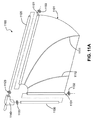
図11Aは、2の湾曲したバテン1111、1112を有する例示的な翼1100の分解図を示しており、マスト要素1120は翼の翼メンブレン1101の前縁スリーブ1121内に挿入される。スリーブ1121はそれ自体に翼形メンブレンを引き込むことで形成することができる、および/またはマスト要素を受け取る管、すなわち翼形が巻き付けられて固定できる管を有しうる。弾性ワッシャー1122、1123が、前縁スリーブ1121の両側のマスト要素1120の近位および遠位部分に配置されうる。付け根の桁要素1130または支材要素は、翼の翼メンブレン1101の付け根の桁スリーブ1131内に挿入される。支材スリーブ1131はそれ自体に翼を引き込むことで形成することができる、および/またはマスト要素を受け取る管、すなわち翼が巻き付けられて固定される管を有しうる。弾性ワッシャー1132、1133が、支材スリーブ1131の両側の付け根の桁要素1130の遠位および近位部分に配置されうる。マスト要素1120および支材要素1130は、コーナー要素1140、またはアームソケット要素(図示せず)に受け取られるよう構成されたアームフィットメントと係合する。図11Bは、組み立てられた例示的な翼1100を図示している。メンブレンは、梱包発泡シートといった1/32インチの厚さを有するような、押出し成型されたポリエチレン発泡シートで作ることができる。バテン1111、1112、マスト要素1120、支材要素1130、およびスリーブ管1121、1131は、炭素フィラメントで作ることができる。翼1100はさらに、付け根の桁または支材に近い、重なっているメンブレンから作られ、メンブレンの層と発泡繊維の層の間に位置するポケットを有しうる。発泡繊維は振動を減衰させて、フラップの音響効果を緩和することができる。
FIG. 11A shows an exploded view of an
図12は、左のフラップ駆動アセンブリ1210と右のフラップ駆動アセンブリ1220を具える例示的なフラップ駆動アセンブリおよび機構1200を示し、1対の図10Bの実施形態の組み合わせと類似しており、左右のフラップ駆動アセンブリはそれぞれ4つのキャプスタンを有しているが、1つの翼アセンブリについて1つのアームを有している。図12の実施形態は、フラップ駆動アセンブリ1200の左のアーム部分1211と係合している左翼アセンブリ1230を示しており、左のアセンブリ1210のアーム1211は左のアセンブリ1210の第3のキャプスタン1212と係合している。図12の実施形態は更に、右アセンブリ1220のアーム1213と係合している右翼アセンブリ1230を示しており、右のアセンブリ1220のアーム1213は、右のアセンブリ1220の第4のキャプスタン1212と係合している。この例示的な実施形態では、読み込み命令を有する中央処理装置(CPU)等のプロセッサは、翼の位置センサ1240、1241からの入力をモニタすることで左右のモータの同調を維持する。ピッチ制御への影響は前後のエンジンスロットル操作の差異によって生成することができる。ヨー制御への影響は前方ストロークと後方ストロークのスロットル操作の差異によって生成することができ、ロール制御への影響は中間ストロークと終端ストロークのスロットル操作の差異によって生成することができ、付け根の桁または支材に取り付けられた羽ばたき運動スプリング等の翼に取り付けたスプリングでなされうる。従って、翼の偏角を調整するサーボ機構は、この例示的な実施形態には必要ではない。
FIG. 12 shows an exemplary flap drive assembly and
図13は、付け根の桁または支材の移動を制限する例示的なアセンブリ1300を示している。2のサーボ機構1310、1320が使用され、アイレット1370−1379を介して送られたストリングまたはコード、およびプーリーシステム1330によって支材停止部1360−1363の位置をそれぞれ制御し、各翼(図示せず)の偏向差を可能にする。各支材停止部は引っ張られているロッカ状のプーリー要素に固定されており、ストリングを引き込むと対向する支材停止部の間の角度が開く。1対の支材停止部がフラップアセンブリのアームにそれぞれ配置され、これにより、支材停止部はフラップ動作するアームと共に回転して、支材の近位端の移動を制限する。従って、ロールおよびヨーへの影響は、支材停止部の位置によりマストがフラップ動作している間に生成することができる。空気力は、支材をストロークの付随する支材停止部上、すなわち、前方ストローク中は後方の支材停止部および後方ストローク中は前方の支材停止部で停止させる傾向がある。ハンドルバー状の構造1380がピッチサーボ機構1381を介して回転1382できるように設けられ、マストのフラップ動作と併せて、各翼の支材停止部を広げる、あるいは引き込むことができる。ハンドルバー状の構造1340、1350を用いて、ストローク中に支材停止部を継続的に移動させることによりフラップ動作時にピッチへの影響を生成することができる。図14Aは図13の例示的なアセンブリ1400の側面図を示しており、1対のストリングまたはコード1410、1412が、ハンドルバー状の構造1416のアームの端部でアイレット1414を通って延びて図示されている。図示されたサーボ機構は、フラップモータおよびフラップ駆動アセンブリの近くに配置することができる。支材停止部1363はプーリー要素に取り付けることができ、プーリー要素自体は支持構造に張った状態で取り付けられる。図14Bは、ピッチサーボ機構1318によるハンドルバー要素1416の回転1430を示しており、ストロークの特定の部分に対してストリングは支材停止部1363、1362を引き込むことが可能となる。すなわち、マスト(この図の頁の外)が回転すると、ストリングはプーリー上の支材停止部を引き込む。図14Bは、ピッチサーボ機構1318によるハンドルバー要素の回転1431を示しており、ストリングは支材停止部1362、1363を引き込み、ストロークの特定の部分に対してそれぞれの支材停止部間の角度は広がる。
FIG. 13 illustrates an
マストおよび付け根の桁または支材の面に対して直角な図では、図15Aはストリング1510の動作を示しており、支持構造上の回動点の周りに第1のプーリー要素(この図では、第2のプーリー要素1530によって遮られている)を回転させることにより、第1の支材停止部1520の位置を回転させる。さらに図15Aは、この例では動かない第2のストリング1511を図示しており、ストリングにおける張力が取り付けられた第2のプーリー要素1530における張力と釣り合っているため、第2の支材停止部1521は静止位置、すなわちストロークにおける位置に残っている。図15Bは図13の底面図を示しており、支材停止部1360−1363は、支材の比較的大きい偏角まで広げられている。図15Bは図13の底面図を示しており、アームのフラップ動作は翼をストロークにおける相対角度を変化させ、支材停止部1360−1363は図15Bと同じ角度に拡がったままの状態である。すなわち、図14Aの実施例のストローク時、偏角に影響を与えないようにピッチアクチュエータは中立位置にあってもよい。
In a view perpendicular to the surface of the mast and root spar or strut, FIG. 15A shows the operation of the
図16は、翼アセンブリ1600および支材停止部1614、1616用の1組のプーリー要素を図示している。2のストリングを適用すると、それぞれを双方向サーボ機構(図示せず)の制御下にすることができ、各プーリー要素を引っ張られた状態で配置し、各支材停止部を他から独立して角度を配置することができる。図17Aは例を示しており、各支材停止部1710、1720は、前方ストロークおよび後方ストロークの双方に対して比較的大きい偏角ができるように配置されている。停止部が広く開いた状態では、このようにフラップしている翼は比較的小さい迎え角を有し、比較的小さい推力を生成する。対照的に、図17Bは例を示しており、各支材停止部1711、1721は、前方ストロークおよび後方ストロークの双方に対して比較的小さい偏角ができるように配置されている。停止部が狭い位置に開いた状態では、このようにフラップしている翼は比較的大きい迎え角を有し、比較的に大きい吹き下ろしを伴いながら比較的大きい推力を生成する。図18A−18Cは、支材停止部を左または右に調整し、真のヨーモーメントを生成することによって生じたヨー制御1800を示している。図18Aは、ヨーチャネルに対して中間地点にある停止部1810、1812を示している。すなわち、フラップアームは後方ストロークと同一の前方ストロークにおける支材の偏角を有しており、すなわち、推力ベクトルは航空機の「上方」方向に調整される。図18Bは右に付勢された停止部1814、1816を示しており、翼のフラップ運動および2つの停止部の間の支材の動作、すなわち前方ストローク時の1の停止部と後方ストローク時の他方の停止部の間の支材の動作は、右向き成分を有する推力ベクトルを生成する。従って、フラップ運動している間、右に付勢された停止部が生じている機体は、機首を左にする制御を実行する。図18Cは左に付勢された停止部1818、1820を示しており、翼のフラップおよび2つの停止部の間の支材の動作、すなわち前方ストローク時の1の停止部と後方ストローク時の他方の停止部の間の支材の動作は、左向き成分を有する推力ベクトルを生成する。従って、フラップ運動している間、左に付勢された停止部が生じている機体は、機首を右にする制御を実行する。
FIG. 16 illustrates a set of pulley elements for
図19は、支材の移動を制御する代替的な手段1900を示しており、コードまたはストリングがサーボ機構(図示せず)によって制御され、ヨーク1910のアイレット1911、1912を介して支材1920に送られて、支材の遠位部分で固定されている。図20Aおよび20Bは、フラップ運動時の支材2024の向きの制御2010、2020を図示しており、支材2024の方向付けは、図20Aのように、コード2030またはストリングを回転させて後方ストロークに対して支材を配置し、コード2022またはストリングを回転させて後方ストロークに対して支材2024を配置することによって行うことができる。偏角の配置はストローク中に行われ、その結果、サーボ位置コマンドを連続的に変化させること基づいて(例えば、周期的な調整により)ピッチ、ヨー、およびロールに対する制御への影響が生じうる。
FIG. 19 shows an alternative means 1900 for controlling the movement of the struts, where the cord or string is controlled by a servo mechanism (not shown) and applied to the
バングと呼ばれる支持要素をボールジョイントである複数軸ジョイントを介して翼−支材構造に取り付け、支材とほぼ平行に配置することができる。支材またはバングはヨークと係合することができ、メンブレンの羽ばたき運動はヨークの動作に影響されることがある。図21Aは、支材移動を制御する他の手段として、3軸のサーボ支材および/またはバングアセンブリ2100を示しており、支材(またはバング)を保持しているヨーク2110は、羽ばたき運動、すなわちストローク時の両翼に対する翼メンブレンの緩みの影響を増減させて、第1のサーボ機構および歯車装置2120を介してピッチ制御への影響を生成し;ストローク時の翼間の羽ばたき運動量に差異を生じさせて、第2のサーボ機構および歯車装置2130を介してロール制御への影響を生成し;第3のサーボ機構および歯車装置2140を介して支材の移動に付勢を任意に生じさせて、ヨー制御に対して羽ばたき運動の差異を生成することができる。従って、アセンブリ2100は航空機の機体にヨークに対する複数軸の向きを提供し、ストローク時の翼メンブレンの羽ばたき運動を調整して3軸の制御を行う。
Support elements called bangs can be attached to the wing-support structure via a multi-axis joint, which is a ball joint, and can be arranged substantially parallel to the support. The strut or bang can engage the yoke, and the flapping movement of the membrane can be affected by the operation of the yoke. FIG. 21A shows a three-axis servo strut and / or
図21Bは、図10B(1000)に示すようなフラップ機構2100と、付け根の桁または支材と、図21A(2100)に示すような制御機構とを有する例示的な航空機を示している。図21Bの実施形態では、各翼2160の支材2161がヨーク2110と係合する。さらに、図示された上記のフラップ機構は、電源および処理モジュール2170である。この機体は、任意のスタンド2180を有しうる。図22は、図9(900)に示すようなフラップ機構と、付け根の桁または支材と、図21Aに示すような制御機構とを有する例示的な航空機2200の一部を図示しており、付け根の桁2161、2262はヨーク2110と係合する。図23は、図9(900)に示すようなフラップ機構と、付け根の桁または支材の他の実施形態と、図21A(2100)に示すような制御機構を有する例示的な航空機2300の一部を示しており、付け根の桁2161、2262はヨーク2110と係合する。図24Aは、左翼2410の方へと傾き、右翼2420から離れて位置決めされたヨーク2110を示している。各翼のマストはフラップ平面内に残っており、メンブレンが右翼2420よりも緩んでいるため左翼2410の羽ばたき運動または翼のゆるみの影響は大きくなり、その結果、左翼2410は右翼2420よりも推力を生成しない。図24Bは、右翼2410の方へ傾き、右翼2420から離れているジンバルヨークを示している。各翼のマストはフラップ平面内に残っており、右翼の羽ばたき運動は左翼2410の羽ばたき運動よりも大きく、その結果、右翼2420は左翼2410よりも推力を生成しない。図24Aおよび24Bは、この例示的な実施形態に対するロール制御への影響を図示している。ヨークを有する制御ジンバルは付け根の桁の後縁端部を直接動かして、翼の羽ばたきを操作することができる。
FIG. 21B shows an exemplary aircraft having a
図25Aは支材バングシステム2500を示しており、単独の支材バング2510がヨーク2110と係合し、調整可能な支材停止部レバー2512に対する構造支持部2511を提供している。アセンブリに位置する複数軸のヨークによって提供されたピッチおよびロール制御からヨー制御を分離するには、付け根の桁2520を調整可能な支材停止部2521、2522の間で自由に移動できるようにして、バング2510または他の支持要素がヨーク2110のヨークアーム2111、2112の運動を複数軸ジョイント2550における翼の方向に接続させることによって実現しうる。従って、ロール制御は、図21Aのアセンブリと類似しているがヨーのサーボ機構歯車ボックスがない、サーボ機構アセンブリの2軸のジンバルのヨークの位置を片側に傾けることで行われ、ピッチ制御は、ヨークの位置を前後に傾けることで行うことができる。ケーブル2513などを介してレバーを引っ張るまたは緩めることにより、第3の(ヨー)サーボ機構を用いてレバー2512に取り付けられた支材停止部2521、2522の向きを制御する。図25Bはレバー2512の実施形態を示しており、張った状態でバング構造2511に取り付けられ、支材バング構造2511に取り付けられたケーブル2513を介して作動させることができる。図25Cは、レバー2512を引っ張り、支材2590が移動する支材停止部間の距離を短くするケーブル2513を図示している。図25Dは、レバー2512を緩め、支材2590の移動距離を長くできるケーブル2513を示している。
FIG. 25A shows a
図26は、航空機の実施形態の制御および推進システム2600の例示的なトップレベルブロック図である。アドレス可能なメモリを有し、電池を含む搭載型動力供給装置2608を利用する中央処理装置(CPU)2602は、少なくとも1の駆動モータ、すなわち推力またはフラップモータ2610への電圧命令を生成する。この命令はパルス幅変調(PWM)されうる。ホールセンサをクランクシャフトに配置することができ、これにより、CPU2602からフラップ振動数を得たり、提供することができる。幾つかの実施形態では3の制御サーボ機構2612、2614、2616があり、図26はピッチ双方向サーボ2612、ロール双方向サーボ2614、およびヨー双方向サーボ2616への命令を生成するCPU2602を示している。位置センサ2624、2626、2628は、それぞれのサーボ位置2610、2612、2614、2616をCPU2602にフィードバックすることができる。2つの2軸ジャイロスコープ2618、2620といった角速度測定装置を用いて、ヨー角速度、ピッチ角速度、およびロール角速度を提供できる。CPU2602はアップリンクによって無線制御装置2622からの外部命令信号を提供することができ、CPU2602はダウンリンクによって状態または他の情報を提供することができる。一般に、CPU2602は送受信機を介して外部ノードと通信することができる。電気および/または電子要素は、搭載型動力供給装置および局部的化学電池要素2608を介して動力供給することができる。
FIG. 26 is an exemplary top level block diagram of a control and
図27はフラップ振動数コントローラ2700のトップレベルブロック図であり、命令フラップ振動数FC2702および派生フラップ振動数Fest2704は異なり、フラップ振動数エラーε2706を生成する。フラップ振動数エラー2706は積分されてゲインKI2708を掛けられ、フラップ振動数エラー2706はゲインKP2710を掛けられる。これら2つの結果はゲインKFF2712を掛けたフラップ振動数の結果と共に組み合わされ、フラップするための駆動または推力モータへのメインモータ電圧命令などの命令を生成する。ゲインまたはゲインを生成するステップと共に、フラップ振動数コントローラはマシン読み取り可能な言語で表現され、航空機のプロセッサによってアクセスできるメモリに記録され、フラップモータの電圧命令を生成するよう実行することができる。
FIG. 27 is a top level block diagram of the
図28はサーボコントローラ2800の例示的なトップレベルブロック図であり、位置命令dC2802は測定位置dMEAS2804とは異なり、サーボ位置エラーdε2806を生成し、次いで、サーボ位置エラーにサーボゲインKδ2808を掛けてサーボモータ電圧命令u2810を生成する。サーボチャネルでは、ゲインまたはゲインを生成するステップと共に、サーボコントローラ2800はマシン読み取り可能な言語で表現され、航空機のプロセッサによってアクセスできるメモリに記録され、1以上のサーボに対するサーボモータ電圧命令を生成するよう実行することができる。
FIG. 28 is an exemplary top-level block diagram of
図29は、ロール、ピッチ、またはヨーの速度制御のために実装されうる角速度コントローラ2900の例示的なトップレベルブロック図である。付勢角速度の測定値2902は、フィルタをかけたジャイロ速度の測定値2904と、スロットルアップした時点、すなわち翼がフラップ運動を始める前に記録された1以上のジャイロ読み取り値に基づくジャイロ速度付勢との差異によって生成されうる。角速度エラーe2906は角速度命令と付勢角速度の測定値2902の差異によって生成されうる。サーボ位置命令δC2908は、角速度命令およびフィードフォワードゲインKFF2910の結果と、角速度エラー2906および比例速度ゲインKP2912の結果を組み合わせることによって生成されうる。
FIG. 29 is an exemplary top level block diagram of an
図30は、ロール、ピッチ、またはヨーの速度制御のために実装されうる角速度コントローラ3000の例示的なトップレベルブロック図である。付勢角速度の測定値3002は、フィルタをかけたジャイロ速度の測定値3004と、スロットルアップした時点、すなわち翼がフラップ運動を始める前に記録された1以上のジャイロ読み取り値に基づくジャイロ速度付勢との差異によって生成されうる。デジタル積分器が、経時的な角速度エラーe3006を積分することができる。角速度エラーe3006は、角速度命令と付勢角速度の測定値の差異によって生成されうる。サーボ位置命令δC3008は、ゲインKI3014を掛けた積分された角速度エラーの結果と共に、角速度命令およびフィードフォワードゲインKFF3010の結果と、角速度エラーおよび比例速度ゲインKP3012の結果を組み合わせることによって生成されうる。
FIG. 30 is an exemplary top level block diagram of an
図31は、マストと、付け根の桁と、マストの折り重ね部分3110、付け根の桁の折り重ね部分3110および第1のバテン3130を有するメンブレンとを有する例示的な翼が示されている。図32は図31の翼の断面図を示しており、第1のバテン3130はメンブレン表面に配置されたロッド形状のフィラメントであり、第2のバテン3140は平行六面体形状である。図33は、マスト周囲のメンブレンの回転性能を示す、図31の端面図を示している。図34は図31の翼の断面図を示しており、メンブレン3102は、マスト、または付け根から翼端までの桁が内側に配置される管3400の周りに巻き付けられている。メンブレンの重なる面は、エポキシまたは熱処理によって一部分に接合することができる。図35は取り付ける他の手段を示しており、メンブレンと同一材料であってもよい材料の分離する部分3500を利用して、管3400をメンブレン3103に取り付けている。図36は取り付ける他の手段を示しており、メンブレン縁部3610は端面を見たときにt型の部分3611を有しており、このt型部分または直角の縁面がスリットにそってマスト管3620内に挿入され、マスト要素の圧力により定位置に保持されて熱またはエポキシにより固定することができる。図37は、2のバテンとメンブレン折り重ね部分を有する例示的な翼形を示している。図38は、2のバテンとメンブレン折り重ね部分を有する例示的な翼形を示しており、バテンはメンブレンの重複部3810、3811を有している。図39は、2のバテン3710、3711と、2の折り重ね領域3720、3721を有する図37の翼形を示しており、メンブレン材料は発泡メンブレンである。図40は、バテンがなく、メンブレンの折り重ねがない翼形を示している。図41は、2のバテンと、メンブレンの折り重ねと、マスト4110と付け根の桁4120の間の弓形切欠き領域4100とを有する翼形を示している。図42は、他の例と比較して表面積が狭く、折り重ね領域またはバテンがない、角がある翼形の平面図形を示している。図43は、2の湾曲したバテン4310、4311と、メンブレンの折り重ねを有する発泡メンブレンで作られた翼形を示している。図44は、治具4400に取り付けられたマスト4410および付け根の桁4420と、有効な管4430および4440で翼形を作る治具4400を示している。図45は、作業面に固定されたフィラメント格子を有するメンブレン素材4500を示している。図46は、メンブレン素材上に配置された図44の治具を示している。図47は、マストおよび付け根の桁に沿ってメンブレンを切断し、折り重ねるステップを示している。図50は、メンブレンの表面に利用するバテン5010、5011、および平面図形の残りを切り取るステップを示している。図51は、素材4500からの例示的な翼形5110の取り外しを示している。
FIG. 31 illustrates an exemplary wing having a mast, a root spar, a membrane having a mast fold portion 3110, a root fold portion 3110 and a
本書に記載された要素、成分、ステップ、および機能は更に細分され、組み合わされ、および/または変化させることができ、さらに、本発明の実施形態の概念の範囲内に留まることを当該技術分野における当業者は理解するであろう。従って、開示された実施形態の様々な特徴及び態様は、例によって開示されたような本発明の様々なモードを形成するために、互いに組み合わせる、あるいは置換することができると理解されたい。例示によって本書に開示された本発明の範囲は、上記の特に開示された実施形態に限定すべきではないことを意図している。従って、本発明は例示として開示されており、限定ではなく、以下の特許請求の範囲を参照して本発明の範囲を特定されたい。 It is understood in the art that the elements, components, steps, and functions described herein can be further subdivided, combined, and / or varied, and remain within the concept of embodiments of the present invention. Those skilled in the art will understand. Accordingly, it should be understood that various features and aspects of the disclosed embodiments may be combined with or substituted for each other to form various modes of the invention as disclosed by the examples. It is intended that the scope of the invention disclosed herein by way of example should not be limited to the specifically disclosed embodiments described above. Accordingly, the invention has been disclosed by way of example and should be determined with reference to the following claims, rather than a limitation.
Claims (27)
前記支持構造が、フラップ駆動要素と、当該支持構造に回転可能に取り付けられた第1の翼と、当該支持構造に回転可能に取り付けられた第2の翼とを具え、
前記第1の翼は第1の付け根の桁と前記第1の付け根の桁に取り付けられた第1のメンブレンとを具え、前記フラップ駆動要素を介してフラップして駆動するよう構成されており、
前記第2の翼は第2の付け根の桁と前記第2の付け根の桁に取り付けられた第2のメンブレンとを具え、前記フラップ駆動要素を介してフラップして駆動するよう構成されており、
機体の少なくとも1の軸についての航空機制御が、可変的なメンブレン羽ばたき運動;可変的な付け根の桁の回転運動の制限;および可変的な前記フラップ駆動要素のフラップ角速度の少なくとも1つによって行われることを特徴とする航空機。 In an aircraft with a support structure,
The support structure comprises a flap drive element, a first wing rotatably attached to the support structure, and a second wing rotatably attached to the support structure;
The first wing comprises a first root spar and a first membrane attached to the first root spar and is configured to flap and drive via the flap drive element;
The second wing comprises a second root spar and a second membrane attached to the second root spar, and is configured to flap and drive via the flap drive element;
Aircraft control about at least one axis of the fuselage is performed by at least one of: variable membrane flapping motion; variable root girder rotational limit; and variable flap angular velocity of the flap drive element An aircraft characterized by.
回転中心と回転面を有する回転要素と;
シャフトの周りに装着された第1のキャプスタンであって、前記シャフトは前記回転中心から遠位かつ前記回転面に対して実質的に垂直に前記回転要素に取り付けられた第1のキャプスタンと;
前記支持構造に回転可能に取り付けられた第1のロッカ部材と;
前記第1のキャプスタンおよび前記第1のロッカ部材に回転可能に取り付けられた第1の駆動連結部と;
前記支持構造に回転可能に取り付けられ、第1のロッカリンクを介して前記第1のロッカ部材に回転可能に取り付けられた第1のアームと;
前記シャフトの周りに装着された第2のキャプスタンと;
前記支持構造に回転可能に取り付けられた第2のロッカ部材と;
前記第2のキャプスタンおよび前記第2のロッカ部材に回転可能に取り付けられた第2の駆動連結部と;
前記支持構造に回転可能に取り付けられ、第2のロッカリンクを介して前記第2のロッカ部材に回転可能に取り付けられた第2のアームとを具えることを特徴とする航空機。 The aircraft of claim 1, wherein the flap drive element is:
A rotating element having a center of rotation and a rotating surface;
A first capstan mounted about a shaft, wherein the shaft is attached to the rotating element distal to the center of rotation and substantially perpendicular to the plane of rotation; ;
A first rocker member rotatably attached to the support structure;
A first drive coupling rotatably attached to the first capstan and the first rocker member;
A first arm rotatably attached to the support structure and rotatably attached to the first rocker member via a first rocker link;
A second capstan mounted around the shaft;
A second rocker member rotatably attached to the support structure;
A second drive coupling rotatably attached to the second capstan and the second rocker member;
An aircraft comprising: a second arm rotatably attached to the support structure and rotatably attached to the second rocker member via a second rocker link.
回転中心と回転面を有する回転要素と;
シャフトの周りに装着された第1のキャプスタンであって、前記シャフトが前記回転中心から遠位かつ前記回転面に対して実質的に垂直に前記回転要素に取り付けられた第1のキャプスタンと;
前記シャフトの周りに装着された第2のキャプスタンと;
第3のキャプスタンに装着された第1のアームであって、第1の連結部材が前記第3のキャプスタンを前記第1のキャプスタンに連結している第1のアームと;
第4のキャプスタンに装着された第2のアームであって、第2の連結部材が前記第4のキャプスタンを前記第2のキャプスタンに連結している第2のアームと;
前記第3のキャプスタンを前記第4のキャプスタンに連結している第3の連結部材とを具えることを特徴とする航空機。 The aircraft of claim 1, wherein the flap drive element is:
A rotating element having a center of rotation and a rotating surface;
A first capstan mounted about the shaft, wherein the shaft is attached to the rotating element distally from the center of rotation and substantially perpendicular to the plane of rotation; ;
A second capstan mounted around the shaft;
A first arm mounted on a third capstan, wherein a first connecting member connects the third capstan to the first capstan;
A second arm attached to a fourth capstan, wherein a second connecting member connects the fourth capstan to the second capstan;
An aircraft comprising: a third connecting member connecting the third capstan to the fourth capstan.
第1の回転要素を駆動する第1のモータであって、前記第1の回転要素は回転中心と回転面を有する第1のモータと;
シャフトの周りに装着された第1のキャプスタンであって、前記シャフトは前記回転中心から遠位かつ前記回転面に対して実質的に垂直に前記回転要素に取り付けられた第1のキャプスタンと;
前記シャフトの周りに装着された第2のキャプスタンと;
第3のキャプスタンに装着された第1のアームであって、第1の連結部材が前記第3のキャプスタンを前記第1のキャプスタンに連結している第1のアームと;
第4のキャプスタンを前記第2のキャプスタンに連結している第2の連結部材と;
前記第3のキャプスタンを前記第4のキャプスタンに連結している第3の連結部材と;
第2の回転要素を駆動する第2のモータであって、前記第2の回転要素は回転中心と回転面を有する第2のモータと;
第2のシャフトの周りに装着された第5のキャプスタンであって、前記第2のシャフトは前記回転中心から遠位かつ前記回転面に対して実質的に垂直に前記第2の回転要素に取り付けられた第5のキャプスタンと;
前記第2のシャフトの周りに装着された第6のキャプスタンと;
第7のキャプスタンを前記第5のキャプスタンに連結している第4の連結部材と;
第8のキャプスタンに装着された第2のアームであって、第5の連結部材が前記第8のキャプスタンを前記第6のキャプスタンに連結している第2のアームと;
前記第7のキャプスタンを前記第8のキャプスタンに連結している第6の連結部材と;
前記第1のモータおよび前記第2のモータのフラップ速度を制御する電気回路とを具えることを特徴とする航空機。 The aircraft of claim 1, wherein the flap drive element is:
A first motor for driving a first rotating element, wherein the first rotating element has a rotation center and a rotation surface;
A first capstan mounted about a shaft, wherein the shaft is attached to the rotating element distal to the center of rotation and substantially perpendicular to the plane of rotation; ;
A second capstan mounted around the shaft;
A first arm mounted on a third capstan, wherein a first connecting member connects the third capstan to the first capstan;
A second connecting member connecting a fourth capstan to the second capstan;
A third connecting member connecting the third capstan to the fourth capstan;
A second motor for driving a second rotating element, wherein the second rotating element has a center of rotation and a second motor;
A fifth capstan mounted about a second shaft, the second shaft being distal to the center of rotation and substantially perpendicular to the plane of rotation to the second rotating element; A fifth capstan attached;
A sixth capstan mounted around the second shaft;
A fourth connecting member connecting a seventh capstan to the fifth capstan;
A second arm mounted on an eighth capstan, wherein a fifth connecting member connects the eighth capstan to the sixth capstan;
A sixth connecting member connecting the seventh capstan to the eighth capstan;
An aircraft comprising: an electric circuit for controlling a flap speed of the first motor and the second motor.
スイープ角の移動を有し、付け根の桁およびマストに取り付けられたメンブレンを具える第1のフラップ翼であって、前記メンブレンは前記マストに対する前記付け根の桁の回転によって調整可能な表面張力を有している第1のフラップ翼と;
スイープ角の移動を有し、第2の付け根の桁および第2のマストに取り付けられた第2のメンブレンを具える第2のフラップ翼であって、前記メンブレンは前記第2のマストに対する前記第2の付け根の桁の回転によって調整可能な表面張力を有している第2のフラップ翼とを具えており;
前記第1のフラップ翼は前記航空機から半径方向に延在し、前記第2のフラップ翼は前記航空機の側面から半径方向に前記第1のフラップ翼とは実質的に反対側に延在しており;
前記機体制御アセンブリは、前記第1のフラップ翼の羽ばたき運動と前記第2のフラップ翼の羽ばたき運動の差異を生成することにより、ピッチトルク、ロールトルクおよびヨートルクの少なくとも1つを生成するよう構成されていることを特徴とする航空機。 The aircraft of claim 1, wherein the airframe is configured to provide aircraft control via an airframe control assembly:
A first flap wing having sweep angle movement and comprising a membrane attached to a root girder and a mast, the membrane having a surface tension adjustable by rotation of the root girder relative to the mast; A first flap wing,
A second flap wing having a sweep angle shift and comprising a second membrane attached to a second root spar and a second mast, the membrane being said second relative to said second mast. A second flap wing having a surface tension adjustable by rotation of the base spar of 2;
The first flap wing extends radially from the aircraft, and the second flap wing extends radially from the side of the aircraft in a direction substantially opposite the first flap wing. There;
The airframe control assembly is configured to generate at least one of pitch torque, roll torque, and yaw torque by generating a difference between the flapping motion of the first flap wing and the flapping motion of the second flap wing. An aircraft characterized by
前記第1のフラップ翼がさらに前方へのスイープ偏角と後方へのスイープ偏角を含むスイープ偏角を具えており;
前記第2のフラップ翼がさらに前方へのスイープ偏角と後方へのスイープ偏角を含むスイープ偏角を具えており;
前記機体制御アセンブリがさらに、前記第1のフラップ翼の前方へのスイープ偏角と前記第2のフラップ翼の前方へのスイープ偏角の差異、および前記第1のフラップ翼の後方へのスイープ偏角と前記第2のフラップ翼の後方へのスイープ偏角の差異の少なくとも一方によって、ヨートルクを生成するよう構成されていることを特徴とする航空機。 The aircraft according to claim 8,
The first flap wing further comprises a sweep deflection angle including a forward sweep deflection angle and a backward sweep deflection angle;
The second flap wing further comprises a sweep deflection angle including a forward sweep deflection angle and a backward sweep deflection angle;
The fuselage control assembly further includes a difference between a forward sweep deflection angle of the first flap wing and a sweep deflection angle forward of the second flap wing, and a backward sweep deflection of the first flap wing. An aircraft configured to generate yaw torque by at least one of a difference between a corner and a backward sweep deflection angle of the second flap wing.
前記マストに対して実質的に垂直にフィットメントと係合する桁と;
前記マストの一部の周囲に配置されるマスト管と;
前記桁の一部の周囲に配置される桁管と;
前記桁管および前記マスト管に取り付けられるスクリムと;
前記スクリムに配置され、前記桁および前記マストの交点から半径方向に延在する第1のバテンであって、翼形の縁部に近い遠位端を有している第1のバテンとを具えることを特徴とする翼。 A mast that engages the fitment;
A girder that engages the fitment substantially perpendicular to the mast;
A mast tube disposed around a portion of the mast;
A girder tube disposed around a portion of the girder;
A scrim attached to the beam and the mast tube;
A first batten disposed on the scrim and extending radially from an intersection of the spar and the mast and having a distal end near an airfoil edge; A wing characterized by
スイープ角の移動を有し、前方へのスイープ偏角と後方へのスイープ偏角を含むスイープ偏角を有する第1のフラップ翼と;
スイープ角の移動を有し、前方へのスイープ偏角と後方へのスイープ偏角を含むスイープ偏角を有する第2のフラップ翼とを具える制御アセンブリであって;
前記第1のフラップ翼は前記航空機から半径方向に延在し、前記第2のフラップ翼は前記航空機の側面から半径方向に前記第1のフラップ翼とは実質的に反対側に延在する制御アセンブリを提供するステップと;
前記第1のフラップ翼の前方へのスイープ偏角と前記第2のフラップ翼の前方へのスイープ偏角の差異、および前記第1のフラップ翼の後方へのスイープ偏角と前記第2のフラップ翼の後方へのスイープ偏角の差異の少なくとも一方を生成することにより、ロールトルクおよびヨートルクの少なくとも一方を生成するステップとを含むことを特徴とする方法。 In the method of controlling the aircraft:
A first flap wing having a sweep angle shift and having a sweep deflection angle including a forward sweep deflection angle and a backward sweep deflection angle;
A control assembly having a sweep angle shift and comprising a second flap wing having a sweep deflection angle including a forward sweep deflection angle and a backward sweep deflection angle;
The first flap wing extends radially from the aircraft, and the second flap wing extends radially from the side of the aircraft to a substantially opposite side of the first flap wing. Providing an assembly;
The difference between the forward sweep deflection angle of the first flap wing and the forward sweep deflection angle of the second flap wing, and the backward sweep deflection angle of the first flap wing and the second flap Generating at least one of roll torque and yaw torque by generating at least one of the difference in sweep deflection angle toward the rear of the wing.
スイープ角に基づいて前記第1のフラップ翼の前方への偏角を変化させる、およびスイープ角に基づいて前記第2のフラップ翼の前方への偏角を変化させることにより、ピッチトルクを生成するステップを含むことを特徴とする方法。 The method for controlling an aircraft of claim 23 further includes:
A pitch torque is generated by changing a forward deflection angle of the first flap blade based on a sweep angle, and changing a forward deflection angle of the second flap blade based on a sweep angle. A method comprising steps.
スイープ角に基づいて前記第1のフラップ翼の後方への偏角を変化させる、およびスイープ角に基づいて前記第2のフラップ翼の後方への偏角を変化させることにより、ピッチトルクを生成するステップを含むことを特徴とする方法。 The method for controlling an aircraft of claim 23 further includes:
A pitch torque is generated by changing a backward deflection angle of the first flap blade based on a sweep angle, and changing a backward deflection angle of the second flap blade based on a sweep angle. A method comprising steps.
スイープ角の移動を有し、付け根の桁およびマストに取り付けられたメンブレンを具える第1のフラップ翼であって、前記メンブレンは前記マストに対する前記付け根の桁の回転によって調整可能な表面張力を有している第1のフラップ翼と;
スイープ角の移動を有し、第2の付け根の桁および第2のマストに取り付けられた第2のメンブレンを具える第2のフラップ翼であって、前記第2のメンブレンは前記第2のマストに対する前記第2の付け根の桁の回転によって調整可能な表面張力を有している第2のフラップ翼とを具える制御アセンブリであって;
前記第1のフラップ翼は前記航空機から半径方向に延在し、前記第2のフラップ翼は前記航空機の側面から半径方向に前記第1のフラップ翼とは実質的に反対側に延在する制御アセンブリを提供するステップと;
前記第1のフラップ翼の羽ばたき運動と前記第2のフラップ翼の羽ばたき運動の差異を生成することにより、ピッチトルク、ロールトルクおよびヨートルクの少なくとも1つを生成するステップとを含むことを特徴とする方法。 In the method of controlling the aircraft:
A first flap wing having sweep angle movement and comprising a membrane attached to a root girder and a mast, the membrane having a surface tension adjustable by rotation of the root girder relative to the mast; A first flap wing,
A second flap wing having a sweep angle shift and comprising a second membrane attached to a second root girder and a second mast, wherein the second membrane is the second mast A control assembly comprising a second flap wing having a surface tension adjustable by rotation of said second root spar with respect to
The first flap wing extends radially from the aircraft, and the second flap wing extends radially from the side of the aircraft to a substantially opposite side of the first flap wing. Providing an assembly;
Generating at least one of pitch torque, roll torque, and yaw torque by generating a difference between the flapping motion of the first flap wing and the flapping motion of the second flap wing. Method.
前記第1のフラップ翼がさらに、前方へのスイープ偏角と後方へのスイープ偏角を含むスイープ偏角を具え;
第2のフラップ翼がさらに、前方へのスイープ偏角と後方へのスイープ偏角を含むスイープ偏角を具えており;当該方法が更に:
前記第1のフラップ翼の前方へのスイープ偏角と前記第2のフラップ翼の前方へのスイープ偏角の差異、および前記第1のフラップ翼の後方へのスイープ偏角と前記第2のフラップ翼の後方へのスイープ偏角の差異の少なくとも一方を生成することにより、ヨートルクを生成するステップを含むことを特徴とする方法。 27. A method of controlling an aircraft according to claim 26:
The first flap wing further comprises a sweep deflection angle including a forward sweep deflection angle and a backward sweep deflection angle;
The second flap wing further comprises a sweep deflection angle including a forward sweep deflection angle and a backward sweep deflection angle; the method further includes:
The difference between the forward sweep deflection angle of the first flap wing and the forward sweep deflection angle of the second flap wing, and the backward sweep deflection angle of the first flap wing and the second flap A method comprising the step of generating yaw torque by generating at least one of the differences in the swept deflection angle toward the rear of the wing.
Applications Claiming Priority (3)
| Application Number | Priority Date | Filing Date | Title |
|---|---|---|---|
| US18474809P | 2009-06-05 | 2009-06-05 | |
| US61/184,748 | 2009-06-05 | ||
| PCT/US2010/037540 WO2010141916A1 (en) | 2009-06-05 | 2010-06-04 | Air vehicle flight mechanism and control method |
Publications (1)
| Publication Number | Publication Date |
|---|---|
| JP2012529398A true JP2012529398A (en) | 2012-11-22 |
Family
ID=43298202
Family Applications (1)
| Application Number | Title | Priority Date | Filing Date |
|---|---|---|---|
| JP2012514211A Pending JP2012529398A (en) | 2009-06-05 | 2010-06-04 | Aircraft flight mechanism and control method |
Country Status (8)
| Country | Link |
|---|---|
| US (8) | US8205823B2 (en) |
| EP (1) | EP2437980A4 (en) |
| JP (1) | JP2012529398A (en) |
| KR (5) | KR102161322B1 (en) |
| CN (3) | CN110203389B (en) |
| AU (1) | AU2010256424A1 (en) |
| CA (1) | CA2776485A1 (en) |
| WO (1) | WO2010141916A1 (en) |
Cited By (3)
| Publication number | Priority date | Publication date | Assignee | Title |
|---|---|---|---|---|
| US11077941B2 (en) | 2016-02-29 | 2021-08-03 | Murata Manufacturing Co., Ltd. | Wing flapping apparatus |
| US11136117B2 (en) | 2015-11-04 | 2021-10-05 | Murata Manufacturing Co., Ltd. | Wing flapping apparatus |
| US11254426B2 (en) | 2016-12-15 | 2022-02-22 | Murata Manufacturing Co., Ltd. | Wing unit, wing flapping apparatus, and method of manufacturing wing unit |
Families Citing this family (51)
| Publication number | Priority date | Publication date | Assignee | Title |
|---|---|---|---|---|
| WO2008108892A1 (en) * | 2006-10-30 | 2008-09-12 | Kyriacos Zachary | Inverting wing propulsion system |
| KR102161322B1 (en) | 2009-06-05 | 2020-10-06 | 에어로바이론먼트, 인크. | Air vehicle flight mechanism and control method |
| US9669925B2 (en) | 2011-02-16 | 2017-06-06 | Aerovironment, Inc. | Air vehicle flight mechanism and control method for non-sinusoidal wing flapping |
| WO2012112816A1 (en) * | 2011-02-16 | 2012-08-23 | Aerovironment, Inc. | Air vehicle flight mechanism and control method for non-sinusoidal wing flapping |
| US9199734B2 (en) * | 2012-08-30 | 2015-12-01 | Nanyang Technological University | Motorised device and method of moving the device |
| CN102923303B (en) * | 2012-11-22 | 2014-12-10 | 东北大学 | Wing-flapping flight vehicle capably of taking off and landing automatically and control method thereof |
| DE102013004188B4 (en) * | 2013-03-12 | 2021-09-16 | Festo Se & Co. Kg | Coupling device and flow machine |
| US20160068263A1 (en) * | 2013-04-19 | 2016-03-10 | New York University | Flapping wing device |
| GR20130100619A (en) * | 2013-10-25 | 2015-05-18 | Ιωαννης Γεωργιου Μικρος | Small-sized bird-like flying device and application thereof |
| US10017248B2 (en) * | 2014-04-28 | 2018-07-10 | University Of Maryland, College Park | Flapping wing aerial vehicles |
| CN104260888B (en) * | 2014-10-08 | 2016-06-29 | 哈尔滨工程大学 | A kind of little MAV lift unit |
| CN104482967B (en) * | 2015-01-14 | 2017-01-11 | 东北大学 | Flight parameter testing device of micro-miniature flapping wing air vehicle |
| CN104859856A (en) * | 2015-06-09 | 2015-08-26 | 李维农 | Scheme for improving flapping intensity of flapping-wing aircrafts |
| NL2016130B1 (en) * | 2016-01-21 | 2017-07-25 | Univ Delft Tech | Multiple pairs of flapping wings for attitude control. |
| GB2549252B (en) * | 2016-02-29 | 2021-04-14 | Hatcher William | Airborne vehicle |
| WO2017159038A1 (en) * | 2016-03-15 | 2017-09-21 | シャープ株式会社 | Flapping device for work |
| CN106394897B (en) * | 2016-10-26 | 2018-09-04 | 吉林大学 | A kind of foldable wind resistance flapping wing of flapping-wing MAV |
| CN109398751B (en) * | 2016-12-06 | 2023-07-04 | 昆山鲲鹏无人机科技有限公司 | Method for detecting whether unmanned aerial vehicle wing with tilting mechanism loosens or not |
| CN106585980B (en) * | 2016-12-07 | 2018-08-24 | 郑州轻工业学院 | A kind of foldable flapping wing micro-robot of imitative beetle of four-degree-of-freedom |
| NL2018549B1 (en) * | 2017-03-20 | 2018-09-28 | Univ Delft Tech | Flapping wing mav |
| NL2018958B1 (en) | 2017-05-22 | 2018-12-04 | Univ Delft Tech | Flapping wing aerial vehicle |
| CN107352030B (en) * | 2017-07-05 | 2020-01-14 | 北京航空航天大学 | Micro flapping rotor wing aircraft with double wings flapping differentially |
| CN107867396B (en) * | 2017-11-06 | 2019-11-08 | 北京科技大学 | A kind of flapping-wing aircraft driven by a steering gear and a driving method of the flapping-wing aircraft |
| GB2568897B (en) | 2017-11-29 | 2022-03-09 | Animal Dynamics Ltd | A canopy control system |
| CN109835481B (en) * | 2017-11-29 | 2021-09-28 | 中国科学院沈阳自动化研究所 | Flapping wing aircraft capable of controlling flight through wing surface deformation |
| CN108491558A (en) * | 2018-01-17 | 2018-09-04 | 南京航空航天大学 | Wing is fluttered the design and control method of the thick-and-thin flapping wing aircraft of frequency |
| CN108190013B (en) * | 2018-02-11 | 2021-01-15 | 陆昌新 | A translation flapping wing with real-time control of direction, pitch and self-variable inclination |
| CN109204811B (en) * | 2018-10-10 | 2024-03-19 | 南京航空航天大学 | Flapping wing aircraft with tail wing |
| CN109436320B (en) * | 2018-11-07 | 2023-12-15 | 杭州翼能科技有限公司 | Aircraft |
| GB2582340B (en) * | 2019-03-20 | 2022-12-14 | The Royal Veterinary College | Winged aircraft |
| CN110550204B (en) * | 2019-09-09 | 2021-08-27 | 北京航空航天大学 | Flapping wing mechanism capable of quickly replacing power and power replacing method |
| CN110550205B (en) * | 2019-09-10 | 2020-11-06 | 南宁蜂虎科技有限公司 | Ornithopter steering control method, device and system |
| CN110979664B (en) * | 2019-12-25 | 2021-05-14 | 北京航空航天大学 | A flat-vibrating double-wing flapping hoverer |
| CN111301677A (en) * | 2020-02-29 | 2020-06-19 | 南京航空航天大学 | Hoverable eight-wing flapping-wing aircraft and flight control method thereof |
| CN111348184B (en) * | 2020-03-19 | 2021-07-09 | 山东大学 | A flapping wing structure and aircraft |
| DE102020205600B4 (en) * | 2020-05-04 | 2025-01-23 | Festo Se & Co. Kg | Wing arrangement for use in a flapping-wing aircraft |
| CN112009682B (en) * | 2020-08-06 | 2022-01-25 | 北京航空航天大学 | Bionic flapping wing micro aircraft for realizing high control torque generation based on double-wing differential motion and steering engine gravity center change |
| CN112298552B (en) * | 2020-08-06 | 2022-08-12 | 北京航空航天大学 | A miniature dual flapping-wing aircraft capable of autonomous stability enhancement and control and its control torque generation method |
| RU2753035C1 (en) * | 2020-08-19 | 2021-08-11 | Гафтдин Газдалиевич Газдалиев | Propeller with changing blades |
| CN112078790B (en) * | 2020-09-03 | 2022-04-19 | 哈尔滨工业大学(深圳) | Flapping wing driving device and aircraft |
| CN112078791B (en) * | 2020-09-10 | 2022-07-05 | 哈尔滨工业大学(深圳) | Flapping wing aircraft |
| CN112224408B (en) * | 2020-10-12 | 2025-01-14 | 仿翼(北京)科技有限公司 | Aircraft and method for controlling the same |
| CN112224406A (en) * | 2020-10-12 | 2021-01-15 | 仿翼(北京)科技有限公司 | Flapping wing aircraft and method for controlling flapping wing aircraft |
| CN112429224B (en) * | 2020-11-30 | 2024-04-12 | 河海大学常州校区 | Flapping wing flying device and ornithopter |
| KR102335485B1 (en) * | 2021-05-25 | 2021-12-03 | 세종대학교산학협력단 | Quad-flapper capable of controlling yaw moment |
| CN113335522B (en) * | 2021-06-23 | 2022-12-23 | 中国矿业大学 | A high-pressure gas-driven gliding flapping-wing robot |
| DE102021118515B3 (en) * | 2021-07-18 | 2022-02-10 | Irina Rodionova | Fin drive for a water or land vehicle for use in a gaseous environment |
| CN115196013A (en) * | 2022-08-23 | 2022-10-18 | 沈阳航空航天大学 | A multi-degree-of-freedom flapping-wing aircraft with a lifting device |
| CN115743539B (en) * | 2022-11-14 | 2024-05-31 | 西北工业大学 | A large-scale and efficient flapping wing for an efficient flapping-wing aircraft |
| CN115636086A (en) * | 2022-12-23 | 2023-01-24 | 中国空气动力研究与发展中心高速空气动力研究所 | Flapping wing aircraft and rolling flight method thereof |
| CN118683736B (en) * | 2024-08-29 | 2024-11-08 | 青岛理工大学 | Passive wing deflection flapping wing aircraft |
Citations (11)
| Publication number | Priority date | Publication date | Assignee | Title |
|---|---|---|---|---|
| US2584663A (en) * | 1946-06-27 | 1952-02-05 | Gen Electric | Variable warp airfoil |
| US2976739A (en) * | 1959-07-01 | 1961-03-28 | Lewellen Mfg Company | Adjustable pulley |
| US3132620A (en) * | 1960-01-11 | 1964-05-12 | Andrew T Court | Sailboat |
| US3806277A (en) * | 1972-10-26 | 1974-04-23 | A Hill | Propulsion device having at least one flexible blade |
| JPH05178293A (en) * | 1991-12-27 | 1993-07-20 | Komota Masayuki | Flapping airplane |
| US5938150A (en) * | 1995-10-27 | 1999-08-17 | King; Randy J. | Kite with an adjustable airfoil and removable surface |
| US20040195436A1 (en) * | 2001-06-30 | 2004-10-07 | Sinclair Peter Logan | Motion assisting apparatus |
| JP2006087908A (en) * | 2004-08-23 | 2006-04-06 | Mitsubishi Electric Corp | Floating body |
| US20070262194A1 (en) * | 2005-11-08 | 2007-11-15 | Agrawal Sunil K | Mechanism for biaxial rotation of a wing and vehicle containing such mechanism |
| JP2008024049A (en) * | 2006-07-18 | 2008-02-07 | Univ Nihon | Flapping airplane |
| US20080251632A1 (en) * | 2005-07-27 | 2008-10-16 | Kwang Ho Kim | Wing-Flapping Flying Apparatus and Method of Using the Same |
Family Cites Families (124)
| Publication number | Priority date | Publication date | Assignee | Title |
|---|---|---|---|---|
| US1364174A (en) * | 1921-01-04 | Flyiug-machine | ||
| US792154A (en) * | 1904-01-28 | 1905-06-13 | George Mcmullen | Aeronautic apparatus. |
| US920792A (en) * | 1908-01-02 | 1909-05-04 | Julius Uherkovich De Uherkocz | Winged propelling and guiding mechanism for air-ships. |
| US980840A (en) * | 1909-04-09 | 1911-01-03 | Matthew Rozboril | Airship. |
| US1117585A (en) * | 1914-03-28 | 1914-11-17 | Ludwig Marschall | Flying-machine. |
| US1375297A (en) * | 1918-05-28 | 1921-04-19 | Frank J Jurek | Aeroplane |
| US1450480A (en) * | 1918-10-23 | 1923-04-03 | James W Buck | Mechanical bird |
| US1525565A (en) * | 1924-07-30 | 1925-02-10 | James F Bean | Aeroplane |
| US1730249A (en) * | 1926-10-04 | 1929-10-01 | Schmidt John | Airplane |
| US1980002A (en) * | 1931-06-30 | 1934-11-06 | Evan P Savidge | Aircraft |
| US2017534A (en) * | 1934-07-05 | 1935-10-15 | Gray Spencer | Flying machine |
| US2218599A (en) * | 1936-09-28 | 1940-10-22 | Brunner Leopold | Propulsion means, especially for aircraft |
| US2418569A (en) * | 1943-10-13 | 1947-04-08 | Baumann August | Beating wing aircraft |
| US2980187A (en) * | 1957-02-28 | 1961-04-18 | Rodrigo M Smyth-Davila | Helicopter |
| US3085355A (en) * | 1959-07-08 | 1963-04-16 | Gen Precision Inc | Aircraft engine fuel control simulator |
| DE1172961B (en) * | 1962-10-18 | 1964-06-25 | Boelkow Entwicklungen Kg | Rotary wing aircraft |
| US3161376A (en) * | 1963-01-21 | 1964-12-15 | Harold M Lyle | Ornithopter type aircraft |
| US3289770A (en) * | 1963-08-14 | 1966-12-06 | Bolkow Gmbh | Helicopter rotor system |
| US3191889A (en) * | 1964-06-22 | 1965-06-29 | Oran M Roberts | Wing-body aircraft |
| FR1537817A (en) * | 1967-07-17 | 1968-08-30 | Process and machine for the transformation of energy in fluids | |
| US3728814A (en) * | 1972-01-17 | 1973-04-24 | G Ruston | Toy ornithopter wind-driving mechanism |
| DE2503177A1 (en) * | 1975-01-27 | 1976-10-14 | Gar Konrad | SWING AIRPLANE OR SWINGING APPARATUS |
| US4095760A (en) * | 1975-10-10 | 1978-06-20 | James A. Black | Structural skin construction materials and method |
| US4155195A (en) * | 1977-05-05 | 1979-05-22 | Leigh Hunt Desmond | Toy airplane |
| US4428550A (en) * | 1981-07-10 | 1984-01-31 | Evans Hugh G | Vibration-insulating stability improving torque force device |
| US4749149A (en) * | 1982-05-12 | 1988-06-07 | Peter Gruich | Ornithopter-type vehicle, and methods of constructing and utilizing same |
| US4712749A (en) * | 1985-10-11 | 1987-12-15 | Duke Fox | Means for and methods of controlling ornithopters |
| US4793573A (en) | 1987-06-12 | 1988-12-27 | Kelfer James W | Figure eight wing drive |
| FR2640518B1 (en) * | 1988-12-20 | 1991-03-22 | Ruymbeke Gerard Van | FLYING TOY MOVED BY BEATS OF WINGS, AND METHOD FOR AUTOMATICALLY LOCKING WINGS AT THE END OF FLIGHT |
| US5170965A (en) * | 1991-05-01 | 1992-12-15 | Hiroaki Yasuda | Hang glider which can fly by human strength |
| CN1067625A (en) * | 1991-06-08 | 1993-01-06 | 白在衷 | insect bionic flapping wing aircraft |
| US5711496A (en) * | 1995-06-30 | 1998-01-27 | Nusbaum; Steve R. | STOL aircraft and wing slat actuating mechanism for same |
| US5899408A (en) * | 1997-04-14 | 1999-05-04 | Bowers, Jr.; Kenneth R. | Ornithopter |
| US5915650A (en) * | 1997-07-10 | 1999-06-29 | Petrovich; Enrique G. | Aircraft wing with dual axis mobility |
| US6082671A (en) * | 1998-04-17 | 2000-07-04 | Georgia Tech Research Corporation | Entomopter and method for using same |
| CN2378287Y (en) * | 1998-06-19 | 2000-05-17 | 杨渤海 | Manpower ornithopter |
| US6012962A (en) * | 1999-02-05 | 2000-01-11 | Mattel, Inc. | Toy figure insect having articulated wings and appendages |
| AU1568901A (en) * | 1999-08-30 | 2001-03-26 | Michael J. C. Smith | Wing-drive mechanism and vehicle employing same |
| US6206324B1 (en) | 1999-08-30 | 2001-03-27 | Michael J. C. Smith | Wing-drive mechanism, vehicle employing same, and method for controlling the wing-drive mechanism and vehicle employing same |
| CA2294676A1 (en) * | 2000-01-04 | 2001-07-04 | James A. Arts | Tail-fin 2000 |
| MXPA02007883A (en) * | 2000-02-14 | 2004-10-15 | Aerovironment Inc | AIRCRAFT. |
| CN1429165A (en) * | 2000-04-03 | 2003-07-09 | 威罗门飞行公司 | Liquid hydrogen stratospheric aircraft |
| US6227483B1 (en) * | 2000-04-05 | 2001-05-08 | SUCCESSION CLéMENT THERRIAULT | Wing movement for ornithopters and apparatus of the like |
| US6540177B2 (en) * | 2000-07-28 | 2003-04-01 | Aerodavinci Co., Ltd. | Flying object by flapping motion of wings equipped with compressed air engine |
| US6530540B1 (en) | 2000-11-03 | 2003-03-11 | Shane Chen | Flapping-wing flying device |
| JP3889956B2 (en) * | 2001-02-27 | 2007-03-07 | シャープ株式会社 | Mobile device |
| US6565039B2 (en) * | 2001-03-19 | 2003-05-20 | Michael J. C. Smith | Wing-drive mechanism and vehicle employing same |
| US20020165524A1 (en) * | 2001-05-01 | 2002-11-07 | Dan Sanchez | Pivot point arm for a robotic system used to perform a surgical procedure |
| US6766138B2 (en) * | 2001-08-24 | 2004-07-20 | Xerox Corporation | Variable length transfer assist blade |
| GB0122677D0 (en) * | 2001-09-20 | 2001-11-14 | Tomas Eric E | Toy ornithopter aircraft |
| DE10147827A1 (en) | 2001-09-27 | 2003-04-24 | Airbus Gmbh | Device for changing the transverse drive size of an aircraft main element, preferably with a flat trailing edge |
| KR100451984B1 (en) * | 2001-11-16 | 2004-10-08 | 주식회사 뉴로스 | Power-Driven Ornithopter |
| DE10156733B4 (en) * | 2001-11-19 | 2006-04-20 | Eads Deutschland Gmbh | Aerodynamic profile with adjustable flap |
| US6938853B2 (en) * | 2002-03-15 | 2005-09-06 | University Of Maryland, College Park | Biomimetic mechanism for micro aircraft |
| US6824094B2 (en) * | 2002-06-06 | 2004-11-30 | Charron Richard | Power assembly for ornicopter |
| US6802473B2 (en) | 2002-06-14 | 2004-10-12 | Richard Charron | Ornithopter with flexible fuselage |
| JP4115349B2 (en) * | 2002-07-12 | 2008-07-09 | シャープ株式会社 | Flapping levitation moving device |
| AU2003304181A1 (en) * | 2002-10-15 | 2005-01-04 | United States Of America, As Represented By The Administrator Of The National Aeronautics And Space Administration | Resonant wingbeat tuning circuit using strain-rate feedback for ornithoptic micro aerial vehicles |
| US6659397B1 (en) * | 2002-10-18 | 2003-12-09 | Richard Charron | Control system for ornithopter |
| AU2003302245A1 (en) * | 2002-12-09 | 2004-07-29 | University Of Florida | Bendable wing for micro air vehicle |
| JP4011538B2 (en) | 2003-01-16 | 2007-11-21 | シャープ株式会社 | Flapping equipment |
| US7107842B2 (en) * | 2003-05-10 | 2006-09-19 | The Regents Of The University Of California | Angular rate sensor using micro electromechanical haltere |
| US7036769B2 (en) * | 2003-05-14 | 2006-05-02 | The Regents Of The University Of California | Microstructures using carbon fiber composite honeycomb beams |
| KR20040102668A (en) * | 2003-05-28 | 2004-12-08 | 배한욱 | Flapping Mechanism |
| GB0314119D0 (en) * | 2003-06-18 | 2003-07-23 | Sinclair Peter | Moving apparatus |
| US20070138339A1 (en) * | 2003-06-18 | 2007-06-21 | Sinclair Peter L | Motion assisting apparatus for flying objects |
| KR20050003677A (en) * | 2003-07-03 | 2005-01-12 | 배한욱 | Rotation flapping mechanism |
| KR100534021B1 (en) * | 2003-07-08 | 2005-12-07 | 한국과학기술연구원 | Wing Actuator Using 3-fold-linkage |
| FR2862602B1 (en) * | 2003-11-24 | 2007-02-16 | Gerard Roger Aldin | STABILIZED IMMERSION FLOAT VESSEL BY ELECTRONIC CONTROL OF MOBILE MASS POSITIONS AND IMMIGRANT FINAL ORIENTATIONS |
| JP2005173968A (en) * | 2003-12-11 | 2005-06-30 | Sharp Corp | Tracking robot system and tracking robot used therefor |
| US8181907B2 (en) * | 2004-01-12 | 2012-05-22 | Smith Michael J C | Wing-drive mechanism and vehicle employing same |
| US6783097B1 (en) * | 2004-01-12 | 2004-08-31 | Michael J. C. Smith | Wing-drive mechanism and vehicle employing same |
| US6959895B2 (en) * | 2004-02-04 | 2005-11-01 | The United States Of America As Represented By The Secretary Of The Navy | Dual wing-pair air vehicle |
| US20050269447A1 (en) | 2004-06-08 | 2005-12-08 | Chronister Nathan J | Ornithopter with independently controlled wings |
| US7007889B2 (en) * | 2004-06-15 | 2006-03-07 | Richard Charron | Flexible airfoils and method |
| JP4142034B2 (en) | 2004-06-24 | 2008-08-27 | シャープ株式会社 | Mobile device |
| US7255305B2 (en) * | 2004-11-02 | 2007-08-14 | Milan Dennis Earl | Flying device utilizing natural principles |
| JP2005119658A (en) * | 2004-11-29 | 2005-05-12 | Koji Isogai | Ornithopter and flapping flight method |
| US20060144992A1 (en) * | 2004-12-07 | 2006-07-06 | Jha Akhllesh K | Transformable fluid foil with pivoting spars |
| US7368860B2 (en) * | 2005-02-11 | 2008-05-06 | The Regents Of The University Od California | High performance piezoelectric actuator |
| US20060180953A1 (en) * | 2005-02-11 | 2006-08-17 | The Regents Of The University Of California | System and method for constructing and operating a high performance piezoelectric actuator |
| US7341222B1 (en) * | 2005-04-07 | 2008-03-11 | The United States Of America As Represented By The United States Department Of Energy | Micro-unmanned aerodynamic vehicle |
| US7350745B2 (en) * | 2005-06-11 | 2008-04-01 | Livingston Donald S | Apparatuses and methods for applying forces to a structure utilizing oscillatory wing motions in a fluid |
| CN100333969C (en) * | 2005-07-07 | 2007-08-29 | 中国航天科技集团公司第十一研究院 | Bionic flapping method for minisize aircraft |
| US20100282897A1 (en) * | 2005-08-17 | 2010-11-11 | Chang Industry, Inc. | Unmanned Aerial Surveillance Device |
| JP4150799B2 (en) * | 2005-08-30 | 2008-09-17 | 国立大学法人九州工業大学 | Flapping flight equipment |
| US20070210207A1 (en) * | 2006-03-06 | 2007-09-13 | Wei-Hsiang Liao | Flying wing rotation mechanism of micro air vehicle |
| US20070205322A1 (en) * | 2006-03-06 | 2007-09-06 | Wei-Hsiang Liao | Micro aviation vehicle |
| WO2008108892A1 (en) * | 2006-10-30 | 2008-09-12 | Kyriacos Zachary | Inverting wing propulsion system |
| NO325284B1 (en) | 2007-02-13 | 2008-03-17 | Proxflyer As | Flight direction control system |
| US20090008507A1 (en) | 2007-03-28 | 2009-01-08 | Jerome Pearson | Aircraft wing |
| US7607610B1 (en) * | 2007-04-23 | 2009-10-27 | Robert Sterchak | Ornithopter having a wing structure and a mechanism for imparting realistic, bird-like motion thereto |
| CN201052838Y (en) * | 2007-05-29 | 2008-04-30 | 吴思泉 | Manpower aircraft |
| CN201183610Y (en) * | 2007-09-10 | 2009-01-21 | 黄光富 | Ornithopter |
| FR2921340B1 (en) * | 2007-09-20 | 2011-09-09 | Univ Paris Sud | FLYING WING ENGINE |
| US7954769B2 (en) * | 2007-12-10 | 2011-06-07 | The Boeing Company | Deployable aerodynamic devices with reduced actuator loads, and related systems and methods |
| WO2009088113A1 (en) * | 2008-01-11 | 2009-07-16 | Microaerobot Co., Ltd. | Remote-controlled fluttering object capable of flying forward in upright position |
| TW200930619A (en) * | 2008-01-15 | 2009-07-16 | Univ Tamkang | Biomimetc micro air vehicle with 8-shaped flapping wing trajectory |
| US7937881B2 (en) * | 2008-03-27 | 2011-05-10 | Craig Allen Price | Bird decoy |
| CN201214485Y (en) * | 2008-05-04 | 2009-04-01 | 张彦勇 | Bionic flapping-wing air vehicle |
| CN101337582A (en) * | 2008-08-19 | 2009-01-07 | 宋兆会 | Manpower running type flapping-wing aircraft |
| US8070090B2 (en) * | 2008-09-05 | 2011-12-06 | The United States Of America As Represented By The Secretary Of The Navy | Stop-rotor rotary wing aircraft |
| FR2946317B1 (en) | 2009-06-04 | 2011-06-17 | Eurocopter France | GUIGNOL A VARIABLE RATIO FOR MANUAL AIRCRAFT FLIGHT CONTROL CHAIN WITH ROTATING CAR |
| KR102161322B1 (en) * | 2009-06-05 | 2020-10-06 | 에어로바이론먼트, 인크. | Air vehicle flight mechanism and control method |
| KR101031869B1 (en) * | 2009-06-08 | 2011-05-02 | 건국대학교 산학협력단 | Wing device generating large wing angle |
| EP2460725A4 (en) * | 2009-07-28 | 2017-05-24 | Kyushu Institute of Technology | Flapping flight capable robot |
| GB0922168D0 (en) * | 2009-12-18 | 2010-02-03 | Greenyer Guy T | Ornithopter engine and method for using the same |
| WO2011142864A2 (en) * | 2010-02-11 | 2011-11-17 | President And Fellows Of Harvard College | Passive torque balancing in a high-frequency oscillating system |
| US8167234B1 (en) * | 2010-03-21 | 2012-05-01 | Michael Moore | Insect-like micro air vehicle having perching, energy scavenging, crawling, and offensive payload capabilities |
| US20110278391A1 (en) * | 2010-05-17 | 2011-11-17 | Kotler Andrey | Dragonfly unmanned aerial vehicle |
| US8395298B2 (en) * | 2010-06-21 | 2013-03-12 | Bae Systems Information And Electronic Systems Integration Inc. | Radioisotope fueled rotary actuator for micro and nano vehicles |
| US8382546B2 (en) | 2010-07-05 | 2013-02-26 | Edwin VAN RUYMBEKE | Flying toy able to move by the flapping of wings |
| US8700233B1 (en) * | 2010-07-29 | 2014-04-15 | The United States Of America As Represented By The Secretary Of The Air Force | Method for shaping wing velocity profiles for control of flapping wing micro air vehicles |
| US8800936B2 (en) * | 2011-01-14 | 2014-08-12 | Aerovironment, Inc. | Unmanned aerial vehicle drag augmentation by reverse propeller rotation |
| US9669925B2 (en) * | 2011-02-16 | 2017-06-06 | Aerovironment, Inc. | Air vehicle flight mechanism and control method for non-sinusoidal wing flapping |
| CA2827688A1 (en) * | 2011-02-17 | 2012-08-23 | Georgia Tech Research Corporation | Hovering and gliding multi-wing flapping micro aerial vehicle |
| US20140061374A1 (en) * | 2011-10-25 | 2014-03-06 | Isaiah W. Cox | Method for increasing landing gear effective life and aircraft landing cycles |
| US9258993B2 (en) * | 2012-03-13 | 2016-02-16 | Evolution Decoys Llc | Motion decoy with biaxial wing beat |
| US20130240665A1 (en) * | 2012-03-16 | 2013-09-19 | Borealis Technical Limited | Method for improving efficiency of airport deicing operations |
| CA2846886C (en) * | 2013-03-15 | 2016-02-09 | Francois Matte | Wing flapping mechanism and method |
| US9072981B2 (en) * | 2013-05-15 | 2015-07-07 | Tanous Works, Llc | Hovering toy figure |
| US9428269B1 (en) * | 2015-01-13 | 2016-08-30 | The United States Of America As Represented By The Secretary Of The Air Force | Methods and apparatus to achieve independent six degree control of flapping wing micro air vehicle |
| US10357294B2 (en) * | 2015-07-01 | 2019-07-23 | Trimed, Incorporated | Method of securing a plate to a bone at a fracture site utilizing a detachable inserter |
| US9643718B1 (en) * | 2015-12-18 | 2017-05-09 | Amazon Technologies, Inc. | Simulated ground effect for aerial vehicles |
-
2010
- 2010-06-04 KR KR1020197037865A patent/KR102161322B1/en active IP Right Grant
- 2010-06-04 JP JP2012514211A patent/JP2012529398A/en active Pending
- 2010-06-04 KR KR1020177023451A patent/KR101979133B1/en active IP Right Grant
- 2010-06-04 CN CN201910451460.9A patent/CN110203389B/en active Active
- 2010-06-04 EP EP10784208.0A patent/EP2437980A4/en not_active Withdrawn
- 2010-06-04 AU AU2010256424A patent/AU2010256424A1/en not_active Abandoned
- 2010-06-04 WO PCT/US2010/037540 patent/WO2010141916A1/en active Search and Examination
- 2010-06-04 CA CA2776485A patent/CA2776485A1/en not_active Abandoned
- 2010-06-04 KR KR1020197013203A patent/KR102061468B1/en active IP Right Grant
- 2010-06-04 CN CN201610320131.7A patent/CN105966616B/en active Active
- 2010-06-04 KR KR1020207027538A patent/KR102290333B1/en active IP Right Grant
- 2010-06-04 KR KR1020127000102A patent/KR101773206B1/en active IP Right Grant
- 2010-06-04 CN CN201080034539.9A patent/CN102791578B/en active Active
- 2010-06-07 US US12/795,539 patent/US8205823B2/en active Active
-
2011
- 2011-02-09 US US13/023,772 patent/US8210471B2/en active Active
-
2012
- 2012-06-25 US US13/532,699 patent/US20130168493A1/en not_active Abandoned
-
2014
- 2014-03-05 US US14/198,418 patent/US9950790B2/en active Active
- 2014-04-07 US US14/247,062 patent/US9957044B2/en active Active
-
2017
- 2017-03-13 US US15/457,455 patent/US20170183092A1/en not_active Abandoned
-
2018
- 2018-03-16 US US15/923,878 patent/US10266258B2/en active Active
-
2019
- 2019-03-06 US US16/294,713 patent/US10919623B2/en active Active
Patent Citations (11)
| Publication number | Priority date | Publication date | Assignee | Title |
|---|---|---|---|---|
| US2584663A (en) * | 1946-06-27 | 1952-02-05 | Gen Electric | Variable warp airfoil |
| US2976739A (en) * | 1959-07-01 | 1961-03-28 | Lewellen Mfg Company | Adjustable pulley |
| US3132620A (en) * | 1960-01-11 | 1964-05-12 | Andrew T Court | Sailboat |
| US3806277A (en) * | 1972-10-26 | 1974-04-23 | A Hill | Propulsion device having at least one flexible blade |
| JPH05178293A (en) * | 1991-12-27 | 1993-07-20 | Komota Masayuki | Flapping airplane |
| US5938150A (en) * | 1995-10-27 | 1999-08-17 | King; Randy J. | Kite with an adjustable airfoil and removable surface |
| US20040195436A1 (en) * | 2001-06-30 | 2004-10-07 | Sinclair Peter Logan | Motion assisting apparatus |
| JP2006087908A (en) * | 2004-08-23 | 2006-04-06 | Mitsubishi Electric Corp | Floating body |
| US20080251632A1 (en) * | 2005-07-27 | 2008-10-16 | Kwang Ho Kim | Wing-Flapping Flying Apparatus and Method of Using the Same |
| US20070262194A1 (en) * | 2005-11-08 | 2007-11-15 | Agrawal Sunil K | Mechanism for biaxial rotation of a wing and vehicle containing such mechanism |
| JP2008024049A (en) * | 2006-07-18 | 2008-02-07 | Univ Nihon | Flapping airplane |
Cited By (3)
| Publication number | Priority date | Publication date | Assignee | Title |
|---|---|---|---|---|
| US11136117B2 (en) | 2015-11-04 | 2021-10-05 | Murata Manufacturing Co., Ltd. | Wing flapping apparatus |
| US11077941B2 (en) | 2016-02-29 | 2021-08-03 | Murata Manufacturing Co., Ltd. | Wing flapping apparatus |
| US11254426B2 (en) | 2016-12-15 | 2022-02-22 | Murata Manufacturing Co., Ltd. | Wing unit, wing flapping apparatus, and method of manufacturing wing unit |
Also Published As
Similar Documents
| Publication | Publication Date | Title |
|---|---|---|
| JP2012529398A (en) | Aircraft flight mechanism and control method | |
| JP5922367B2 (en) | Variable shape aircraft | |
| Bouabdallah et al. | Design and control of an indoor coaxial helicopter | |
| CN108594839B (en) | Control method, aircraft and storage medium based on more vectoring technologies | |
| JP2007237946A (en) | Flapping airplane | |
| JPH0933197A (en) | Mixed-missile automatic controller | |
| JP5057472B2 (en) | Telescopic axis stable flight machine | |
| CN108883826A (en) | Power device and single rotor unmanned vehicle | |
| Roshanbin et al. | Precision stationary flight of a robotic hummingbird | |
| KR20220085402A (en) | Propeller apparatus of air mobility | |
| WO2024076290A1 (en) | Single-wing rotorcraft with multiple flight modes | |
| JP7139229B2 (en) | Remote control helicopter drive controller |
Legal Events
| Date | Code | Title | Description |
|---|---|---|---|
| A621 | Written request for application examination |
Free format text: JAPANESE INTERMEDIATE CODE: A621 Effective date: 20130529 |
|
| A977 | Report on retrieval |
Free format text: JAPANESE INTERMEDIATE CODE: A971007 Effective date: 20140320 |
|
| A131 | Notification of reasons for refusal |
Free format text: JAPANESE INTERMEDIATE CODE: A131 Effective date: 20140408 |
|
| A601 | Written request for extension of time |
Free format text: JAPANESE INTERMEDIATE CODE: A601 Effective date: 20140703 |
|
| A602 | Written permission of extension of time |
Free format text: JAPANESE INTERMEDIATE CODE: A602 Effective date: 20140710 |
|
| A02 | Decision of refusal |
Free format text: JAPANESE INTERMEDIATE CODE: A02 Effective date: 20141104 |