JP2012516001A - Power seat switch to prevent simultaneous operation - Google Patents
Power seat switch to prevent simultaneous operation Download PDFInfo
- Publication number
- JP2012516001A JP2012516001A JP2011546548A JP2011546548A JP2012516001A JP 2012516001 A JP2012516001 A JP 2012516001A JP 2011546548 A JP2011546548 A JP 2011546548A JP 2011546548 A JP2011546548 A JP 2011546548A JP 2012516001 A JP2012516001 A JP 2012516001A
- Authority
- JP
- Japan
- Prior art keywords
- switch
- operating member
- switch operating
- guide
- track
- Prior art date
- Legal status (The legal status is an assumption and is not a legal conclusion. Google has not performed a legal analysis and makes no representation as to the accuracy of the status listed.)
- Pending
Links
- 230000000712 assembly Effects 0.000 claims abstract description 14
- 238000000429 assembly Methods 0.000 claims abstract description 14
- 230000000452 restraining effect Effects 0.000 claims description 2
- 210000005069 ears Anatomy 0.000 description 5
- 230000007246 mechanism Effects 0.000 description 3
- 238000010586 diagram Methods 0.000 description 2
- 230000006835 compression Effects 0.000 description 1
- 238000007906 compression Methods 0.000 description 1
- 238000010276 construction Methods 0.000 description 1
- 230000007423 decrease Effects 0.000 description 1
Images


Classifications
-
- H—ELECTRICITY
- H01—ELECTRIC ELEMENTS
- H01H—ELECTRIC SWITCHES; RELAYS; SELECTORS; EMERGENCY PROTECTIVE DEVICES
- H01H25/00—Switches with compound movement of handle or other operating part
- H01H25/06—Operating part movable both angularly and rectilinearly, the rectilinear movement being along the axis of angular movement
-
- B—PERFORMING OPERATIONS; TRANSPORTING
- B60—VEHICLES IN GENERAL
- B60N—SEATS SPECIALLY ADAPTED FOR VEHICLES; VEHICLE PASSENGER ACCOMMODATION NOT OTHERWISE PROVIDED FOR
- B60N2/00—Seats specially adapted for vehicles; Arrangement or mounting of seats in vehicles
- B60N2/02—Seats specially adapted for vehicles; Arrangement or mounting of seats in vehicles the seat or part thereof being movable, e.g. adjustable
- B60N2/0224—Non-manual adjustments, e.g. with electrical operation
- B60N2/0226—User interfaces specially adapted for seat adjustment
- B60N2/0228—Hand-activated mechanical switches
-
- B—PERFORMING OPERATIONS; TRANSPORTING
- B60—VEHICLES IN GENERAL
- B60N—SEATS SPECIALLY ADAPTED FOR VEHICLES; VEHICLE PASSENGER ACCOMMODATION NOT OTHERWISE PROVIDED FOR
- B60N2/00—Seats specially adapted for vehicles; Arrangement or mounting of seats in vehicles
- B60N2/02—Seats specially adapted for vehicles; Arrangement or mounting of seats in vehicles the seat or part thereof being movable, e.g. adjustable
- B60N2/0224—Non-manual adjustments, e.g. with electrical operation
- B60N2/0226—User interfaces specially adapted for seat adjustment
- B60N2/0229—User interfaces specially adapted for seat adjustment characterised by the shape, e.g. switches having cushion or backrest shape
-
- H—ELECTRICITY
- H01—ELECTRIC ELEMENTS
- H01H—ELECTRIC SWITCHES; RELAYS; SELECTORS; EMERGENCY PROTECTIVE DEVICES
- H01H25/00—Switches with compound movement of handle or other operating part
- H01H25/008—Operating part movable both angularly and rectilinearly, the rectilinear movement being perpendicular to the axis of angular movement
-
- H—ELECTRICITY
- H01—ELECTRIC ELEMENTS
- H01H—ELECTRIC SWITCHES; RELAYS; SELECTORS; EMERGENCY PROTECTIVE DEVICES
- H01H9/00—Details of switching devices, not covered by groups H01H1/00 - H01H7/00
- H01H9/20—Interlocking, locking, or latching mechanisms
- H01H9/26—Interlocking, locking, or latching mechanisms for interlocking two or more switches
-
- H—ELECTRICITY
- H01—ELECTRIC ELEMENTS
- H01H—ELECTRIC SWITCHES; RELAYS; SELECTORS; EMERGENCY PROTECTIVE DEVICES
- H01H2300/00—Orthogonal indexing scheme relating to electric switches, relays, selectors or emergency protective devices covered by H01H
- H01H2300/008—Application power seats
Landscapes
- Engineering & Computer Science (AREA)
- Human Computer Interaction (AREA)
- Aviation & Aerospace Engineering (AREA)
- Transportation (AREA)
- Mechanical Engineering (AREA)
- Physics & Mathematics (AREA)
- Electromagnetism (AREA)
- Switches With Compound Operations (AREA)
- Seats For Vehicles (AREA)
Abstract
自動車のシートのためのスイッチ作動部材は第1通路に沿って移動可能で第1機能に関連する第1スイッチを操作するとともに、第2通路に沿って移動可能で第2機能に関連する第2スイッチを操作するスイッチ操作部材を有する。両方の機能が同時に動作するのを規制するために、ガイドは上記スイッチ操作部材の動きを制御する。ガイド部材は、上記スイッチ操作部材と上記ガイドとの間で働き、上記スイッチ操作部材が停止位置から上記通路の他方に沿って動くと、上記スイッチ操作部材が上記通路の一方に沿って動くのを規制する。連動部材は一対のスイッチアセンブリのスイッチ操作部材の間に設けられており、上記スイッチアセンブリの1つの1機能のみを一回、動作させることができる。 A switch actuating member for the seat of the motor vehicle is movable along the first path to operate the first switch associated with the first function and is movable along the second path and associated with the second function It has a switch operating member for operating the switch. A guide controls the movement of the switch operating member in order to regulate the simultaneous operation of both functions. A guide member acts between the switch operating member and the guide, and when the switch operating member moves from the stop position along the other of the passage, the switch operating member moves along one of the passages. regulate. The interlocking member is provided between the switch operating members of the pair of switch assemblies, and only one function of the switch assembly can be operated once.
Description
本発明は電気スイッチに関し、より詳細にはそのようなスイッチを操作し制御するための機構に関する。 The present invention relates to electrical switches, and more particularly to mechanisms for operating and controlling such switches.
電気スイッチはモータなどの電気装置へ、および、電気装置からの電力の流れを制御するのに用いられる。スイッチを閉じると、電力を流すことができ、所望の条件に達すると、スイッチを開いて電力の流れを遮断できる。複数のスイッチを組み合わせてスイッチアセンブリとし、上記スイッチアセンブリを利用して1以上の機能を制御することは、その典型である。例えば、スイッチ制御部材は一方向に動作して電力を1つの装置に供給することができ、他方向に動作して電力を異なる装置に供給できる。 Electrical switches are used to control the flow of power to and from electrical devices such as motors. When the switch is closed, power can be applied, and when the desired conditions are reached, the switch can be opened to interrupt the flow of power. It is typical to combine a plurality of switches into a switch assembly and control one or more functions using the switch assembly. For example, the switch control member can operate in one direction to supply power to one device, and can operate in the other direction to supply power to a different device.
複数の機能を制御するのに用いられる電気スイッチアセンブリの典型的な応用例は自動車のシートである。電気モータを利用してシートの前後の位置、シートの高さ、その傾き、および、シートクッションに対する背もたれの傾きを制御する。これらの各機能は1以上の電気スイッチで制御される電気モータによって達成される。 A typical application of an electrical switch assembly used to control multiple functions is a car seat. An electric motor is used to control the back and forth position of the seat, the height of the seat, its tilt, and the tilt of the backrest relative to the seat cushion. Each of these functions is accomplished by an electric motor controlled by one or more electric switches.
人間工学的な見地によれば、各スイッチの機能性をたやすく理解できるようにスイッチおよびその制御部材を1つにまとめて配置することが適切である。改めて例としての自動車に言及すると、シートの前後の動きを制御するスイッチは、シートの高さを制御するスイッチと共に、スイッチアセンブリに組み込むことができる。背もたれの傾きを調整するスイッチアセンブリはシートクッションスイッチに隣接する位置に配置し、1つにまとまったスイッチ制御部材全体がシート自身を表すように配置することができる。 From an ergonomic point of view, it is appropriate to arrange the switches and their control members together so that the functionality of each switch can be easily understood. Referring again to the example vehicle, the switch controlling the back and forth movement of the seat can be incorporated into the switch assembly together with the switch controlling the height of the seat. The switch assembly for adjusting the tilt of the backrest may be located adjacent to the seat cushion switch, and the entire switch control member may be arranged to represent the seat itself.
複数の機能を単一のスイッチアセンブリに組み込むと、例えば、シートの位置は高さおよび背もたれとは独立して調整できるようにスイッチの独立した操作が保たれる。スイッチは各モータを制御するのに用いられ、それらのスイッチの操作はスイッチを独立して操作できるようにスイッチ作動アセンブリに組み込まれる。そのような配置によって座席の調整が容易になる。 Incorporating multiple functions into a single switch assembly, for example, maintains the independent operation of the switch so that the position of the seat can be adjusted independently of height and backrest. The switches are used to control each motor and the operation of those switches is incorporated into the switch actuation assembly so that the switches can be operated independently. Such an arrangement facilitates seat adjustment.
各モータの操作は、モータにかかる負荷に応じてモータが電流の引き込みを生じさせる。電流の引き込みは、例えば、移動可能距離の終点に達した場合のように、モータが停止しているときに最大である。従ってスイッチ用の電源を設計する際は、モータのそれぞれが停止し、各モータが最大定格電流を引き込む可能生に適応することが必要である。従って、シートに電源を供給するワイヤーハーネスは高電流に適応するように設計しなければならず、その結果比較的に重いゲージになる。同様に、各スイッチの構成要素は高電流に耐えるように製造されなければならない。この結果、追加の支出につながり、電源の設計の重要性が増すことになる。 The operation of each motor causes the motor to draw current according to the load applied to the motor. The current draw is maximum when the motor is at rest, for example when the end of the movable distance is reached. Therefore, when designing a power supply for the switch, it is necessary to adapt to the possibility that each of the motors will be shut down and each motor will draw its maximum rated current. Thus, the wire harness that powers the seat must be designed to accommodate high currents, resulting in a relatively heavy gauge. Similarly, the components of each switch must be manufactured to withstand high currents. This results in additional expense and increases the importance of the power supply design.
このことは、複数のスイッチアセンブリが1つにまとめられ、そして、スイッチアセンブリのそれぞれが複数の機能を制御する時に更に深刻になる。 This becomes even more serious when multiple switch assemblies are brought together and each of the switch assemblies controls multiple functions.
従って本発明の目的は、上記不都合を取り除き、または、軽減することにある。 Accordingly, it is an object of the present invention to obviate or mitigate the above disadvantages.
大まかに言えば、本発明は複数のスイッチのそれぞれを操作できるスイッチ操作部材を備えるスイッチ作動アセンブリを提供する。ガイドはスイッチ操作部材の動きを制御し、スイッチ操作部材と協働し、一度に1つのスイッチだけが確実に動作するようにする。 Broadly speaking, the present invention provides a switch actuation assembly comprising a switch operating member capable of operating each of a plurality of switches. The guide controls the movement of the switch operating member and cooperates with the switch operating member to ensure that only one switch operates at a time.
従って本発明の一側面によると、第1通路に沿って移動可能で第1機能に関連する第1スイッチを操作するとともに、第2通路に沿って移動可能で第2機能に関連する第2スイッチを操作するスイッチ操作部材とを有するスイッチ作動アセンブリが提供される。ガイドは上記スイッチ操作部材の動きを制御し、上記スイッチ操作部材と上記ガイドとの間で働き上記スイッチ操作部材を拘束して上記通路内を動くようにするガイド部材を備える。上記スイッチ操作部材は停止位置を有し、上記停止位置に置いて、上記ガイド部材が上記通路のいずれか一方に沿って動くことができる。上記ガイド部材は、上記スイッチ操作部材が上記通路の他方に沿って動くと、上記スイッチ操作部材が上記通路の一方に沿って動くのを規制するように構成されている。 Therefore, according to one aspect of the present invention, a second switch movable along the first passage and operating the first switch related to the first function and movable along the second passage related to the second function A switch actuation assembly is provided having a switch operating member for operating the The guide controls the movement of the switch operating member, and includes a guide member acting between the switch operating member and the guide and restraining the switch operating member to move in the passage. The switch operating member has a stop position, and in the stop position, the guide member can move along any one of the passages. The guide member is configured to restrict movement of the switch operating member along one of the passages when the switch operating member moves along the other of the passages.
本発明の更なる側面によれば、一対のスイッチ作動アセンブリを備えるスイッチアセンブリが提供される。上記スイッチ作動アセンブリのそれぞれは、各スイッチの操作を制御するように操作可能で各機能を制御する。上記スイッチ作動アセンブリはそれぞれ停止位置から移動可能でスイッチを操作するスイッチ操作部材を備える。上記スイッチ操作部材は互いに重なり選択的に上記スイッチ操作部材のそれぞれと係合可能な連動部材を有する。上記スイッチ操作部材のいずれか一方が上記停止位置から動くと、上記連動部材が他方のスイッチ操作部材に係合し、他方のスイッチ操作部材が上記停止位置から動くのを規制する。 According to a further aspect of the present invention there is provided a switch assembly comprising a pair of switch actuation assemblies. Each of the switch actuation assemblies is operable to control the operation of each switch and controls each function. The switch actuation assemblies are each provided with a switch actuating member which is movable from the rest position and operates the switch. The switch operating members have interlocking members that can overlap one another and selectively engage with the respective switch operating members. When any one of the switch operating members moves from the stop position, the interlocking member engages with the other switch operating member and restricts the other switch operating member from moving from the stop position.
さて、本発明の実施形態を単なる例として添付図面を参照しながら説明する。 Embodiments of the invention will now be described, by way of example only, with reference to the accompanying drawings.
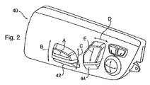
従って、例として図1および図2を参照すると、大略、10で示される自動車のシートは、シートクッション12およびシートバック14を備える。クッション12とバック14とは概略的に示される16で互いに回動し、クッション12とバック14との相対的な位置は電動モータ18によって制御される。クッション12は、レール22上に先に搭載されるベース20上に搭載され、前後の調整ができる。前後の調整は電気モータ24を用いてなされる。
Thus, referring to FIGS. 1 and 2 as an example, the seat of a motor vehicle, generally indicated at 10, comprises a
シートベース20は、モータ30、32によってレール22に対して上下動もできる。上記モータ30、32は、シートベースの傾きだけでなく、その高さをレール22に対して調整できるように独立して操作可能である。同様にモータ34がシートバック14に対するヘッドレストの位置を調整するために設けられている。
The seat base 20 can also move up and down relative to the rail 22 by means of the
モータ18、24、30、32、および34のそれぞれは類似しており、モータの回転運動を直線移動に変換する機構を備える。図1に示すように、モータ24は送りネジ26を回転し、ネジ機構28と協働してシートベース20をレール22に沿って動かす。調整可能なシートの全体構成は自動車産業においてよく知られており、一例としてのみ述べる。本実施形態の操作を十分理解するために、シートの更なる詳細およびその構造を述べる必要はない。
Each of the
モータ18、24、30、32、34は以下に更に詳細に述べるスイッチクラスタアセンブリ40によって制御される。各スイッチアセンブリはそれぞれ制御部材42、44を有し、スイッチ操作部材を介して操作し、モータ18、24、30、32、34への電力の流れを制御するスイッチを操作する。制御部材42は矢印Aで示すように前後方向に移動可能であり、モータ24を制御するスイッチを操作し、シートベース20を制御部材42の動く方向に応じて前方または後方のいずれかへ動かす。制御部材42は、矢印Bで示すように、制御部材42の前方端が動くと、モータ30がシートクッション12の前縁を上げたり下げたりするようにモータ30および32を制御するスイッチをも操作する。同様に、矢印Cで示すように、制御部材42の後方端が動くと、モータ32が対応して動き、クッション12の後方を上げる。従って制御部材42は組み合わせ操作によってシートクッション12の位置を調節できる3つのモータを制御する。
The
同様に、制御部材44は、矢印Dで示すように、制御部材44が時計方向に回転すると、クッション12とシートバック14との角度が大きくなるようにモータ18を制御する。同様に反時計方向に回転すると角度が小さくなる。矢印Eで示すように、制御部材44が垂直方向に動くと、モータ34を制御するスイッチを操作し、その動く方向に応じてヘッドレスト36を上げるかまたは引っ込める。制御部材44は操作を組み合わせてシートバック14およびヘッドレスト36のための最適な形態を提供できる2つのモータ18、34を制御する。ボルスター(bolster)調整、ランバーサポートまたはシートクッションエクステンションなどの追加の機能をスイッチアセンブリに組み込んでも良いが、そのような機能は当該技術分野で周知であるので、今回はそれらを更に論ずる必要はない。
Similarly, as indicated by the arrow D, the
制御部材42、44に関連するスイッチアセンブリは構成が類似しているので1つだけ詳細に説明する。図3から図6に一番よく示されているように、制御部材42はガイドプレート50のスロット48を貫通して突出する尖突46に接続されている。ガイドプレート50はシート10に対して固定され、スロット48は尖突46が充分に動くことができる寸法になっており、制御部材42に関連するスイッチを操作する。尖突46は、一端から延在した一対の耳54を有するスイッチ操作部材52から上方に突出する。
The switch assemblies associated with the
スイッチ操作部材52は、静止ベースプレート56の上方で一対のピンテル(pintel)58a、58bによって支持されており、上記ピンテルはベースプレート56のバネ60によってスイッチ操作部材52の下面を付勢している。図5に一番よく示されているように、ピンテル58は円錐形のくぼみ62と係合し、スイッチ操作部材52に対してベースプレート56を位置決めする。凹部64が、くぼみ62の外方への一方向のピンテル58の動きに適合するように、スイッチ操作部材52の下面に形成されている。
The
バネ60はベースプレート56に固定されたカップ66に支持される。スイッチ操作部材52が動くと、ベースプレート56に対して一方または両方のピンテルがくぼみ62の中心から外れて動き、バネ60を圧縮する。バネ60を圧縮するのに必要な力は操作感触として制御部材42に伝わり、静止位置に制御部材42を戻すための付勢作用となる。凹部64は、制御部材42が凹部64の軸に沿って動くと、一方のバネ60のみの圧縮を引き起こし、制御部材42の動きに応じて一定の感触を伝えるように設けられている。
The
スイッチ操作部材52は、その下面にベースプレート56の孔70を貫通して延在する突起68を有し、ベースプレート56が有するスイッチ72に係合し、そのスイッチを操作する。スイッチ72はそれぞれの電気モータに対する電力供給を制御し、ベースプレート56に対してスイッチ操作部材52が動くと、選択されたスイッチが突起68によって閉成され、モータを所望の様式で動作させることがわかる。
The
ガイドプレート50に対するスイッチ操作部材52の動きはスイッチ操作部材52とガイド50との間に配置されたガイド部材75によって制御される。ガイド部材75はスイッチ操作部材52の上面に円筒状突起として形成された一対の従動部材74、76と、トラックセット78、80とをそれぞれ含む。トラックセット78、80はガイドプレート50中に成形されるか、突部としてガイドプレート50から突出するように成形される。図7でより良く示されるように、トラックセット78、80のそれぞれは直線状トラック82と円弧形トラック84とを備える。各トラックセット78、80の直線状トラック82と円弧形トラック84とは交差してそれぞれの従動部材74、76を受入れる十字形を形成している。従動部材74、76はいずれかのトラック82、84に沿って動くことができ、トラック内でぴったり合い、トラックと従動部材との相対的な横の動きを規制する。トラックセット78、80は直線状トラック82が移動通路の1つを規定する共通軸心上に揃うようにガイドプレート50上に配置されている。円弧形トラック84はそれぞれピンテル58の1つを中心とする。セット78のトラック84はピンテル58bを中心とし、セット80のトラック84はピンテル58aを中心とする。そのため、両トラック84はそれぞれのピンテル58から離れる方向へ収束する。
The movement of the
操作時には、バネ60の弾性によってスイッチ操作部材52を、ガイド部材50に対して安定した停止位置に維持する。この位置で、尖突46はスロット48の中心に位置し、スイッチ72のそれぞれは開いている。従ってどのモータも動作していない。図7(A)で示される停止位置において、従動部材74、76はトラック82、84の交差部分に位置しており、トラックに沿って両方向に自由に動く。
In operation, the elasticity of the
制御部材42が停止位置から動くと、スイッチ72の1つが閉じ、ガイド部材75が協働することによって他のスイッチが動作するのを規制する。制御部材42が反時計方向に動いてシートクッション12の後部を上げると、動きはベースプレート56へ伝わり、スイッチ操作部材52は図7bに示すようにずれる。スイッチ操作部材52はピンテル58上で支持され、ピンテルの1つ58aの周りを反時計方向に回転し、ピンテル58bはくぼみ62からずれる。従動部材76はトラックセット80の脚部84に沿って動き、それによって突起68がモータ32に関連するスイッチ72を操作する。トラック84は、ピン74がセット78のトラック82、84の交差部に実質上とどまるようにピンテル58aに関連するくぼみ62を中心とする円弧形をしている。
When the
従動部材76が脚部84内に位置しているので、脚部84の側部によって従動部材74、76が脚部82に沿って動くのを規制される。従って制御ノブ42を動かしてシートを前後に動かそうとすると、その動きは従動部材76と脚部84との係合によって阻止される。
Because the driven
トラック84が収束していることによっても、従動部材74がセット78のトラック84に入るのを規制する。制御部材42を回転させてモータ30を動作させようとすると、従動部材74がトラック78の脚部84の側面に当接し、ガイド50とスイッチ操作部材52との間の相対的な動きを規制する。従って、制御部材42が回転してモータ30,32の1つを動作させることによって、効果的に他方のモータ24、30または32が動作することを阻止し、1つのモータだけを操作できる。制御部材42を解除すると、スイッチ操作部材がバネ60の付勢力によって停止位置に戻る。制御部材42が時計方向に回転すると、図7Cに示すように同様の作用が起こる。
The convergence of the
図8に示すように、制御部材42が動作して前方または後方へ動く場合、同様の状況が発生する。制御部材42の動きがスイッチ操作部材52に伝えられ、従動部材74、76は直線状トラック82へと移動する。ピンテル58はくぼみ62から外れて、ピンテル58の1つが凹部64へ入る。ひとたび直線状トラックに係合すると、ノブ42の回転が防止され、モータ24だけを動作させることができる。
A similar situation occurs when the
制御部材42を垂直方向に動かすことによって両方のモータ30、32を同時に動作させようとしても、トラック84が収束しているので、従動部材74、76がトラック84へと同時に移動するのを防止する。図9に示すように、従動部材74、76は円弧形トラック84の側面に係合し、制御部材の両方向への移動を規制する。
Vertical movement of the
従って、収束した円弧形トラック84を設けることによって、確実にモータ30、32の1つだけを動作させることができ、ひとたび操作すると、従動部材74、76は直線的に移動できなくなるので、モータ24を動作させることができる。従って、制御部材44でモータを1つだけ動作させることができる。
Thus, by providing a converged
2つのモータだけを制御する必要があっても、制御部材44には同様の配置が設けられている。この配置では、直線状トラック82のみを設けることができるようにトラックセット78に変更が加えられている。従動部材74、76は各直線状トラック82に沿って移動でき、モータ34を動かす。制御部材44が回転すると、従動部材76がセット80のトラック84に係合し、それによってモータ34に関連するスイッチがさらに動作することを阻止する。
Even though only two motors need to be controlled, the
同様に、制御部材42が、回転に対応するスイッチを動作させることのみを必要とする場合(例えば直線動作の無い、モータ30、32のみの動作)、トラック82を省略することができる。トラック84が収束していることで、確実に1つのスイッチのみを動作させることができる。
Similarly, the
スイッチクラスタ40は一対のスイッチアセンブリを利用しており、制御部材42、44の同時動作を回避するために、連動装置が設けられている。連動装置は制御部材のいずれか一方が一度、動くことができるように、制御部材42、44に関連するスイッチ操作部材52の間で動作する。図10から図15を参照すると、スイッチアセンブリはハウジング100内に位置している。片持ち梁状のロッキングアーム102がハウジング100内に成形されており、ハウジング100のベース103の上に突出している。アーム102はハウジング100のベース103に成形された一対のチーク(cheek)104によって位置決めされており、それによってアーム102は一対のチーク104によって規定された面内で撓むように規制されている。アーム102の自由端には、アーム102に対向する側に一対の円筒状のディスク106、108からなるシャトル105が形成され、それぞれ反対方向へ突出している。
The
スイッチアセンブリは図10に示すようにハウジング100内に位置し、スイッチ操作部材52の各耳54が重なるように配置されている。耳54のそれぞれはディスク106、108の1つを嵌合する寸法に形成された円筒状の孔110を有する。孔110の縁は112で示されるように面取りされており、ディスク106、108のそれぞれの周囲と係合するカム面となっている。アーム102は一対の耳54の間に延在しており、シャトル105は孔110と同一軸心である。このことは、図14および図15に一番よく示されているように、シャトル105が、重なり合う一対の耳54の間の間隔よりもわずかに高いことがわかる。従って、各スイッチ操作部材52の停止位置では、孔110が合わさり、ディスク106、108はそれぞれの孔110内に位置し、カム面112に重なる。
The switch assembly is located in the
制御部材42、44の1つが動作すると、対応するスイッチ操作部材52がそれぞれのピンテル上のピボット点の周りを動き、耳54が移動する。スイッチ操作部材52の上記の動きによってカム面112が対応するディスク106、108に係合し、シャトル105を変位させる。アーム102が撓み、ディスク106、108の他方が他方のスイッチ操作部材52の孔110へと移動する。このことは制御部材40に関連する下方のスイッチ操作部材52が移動し、シャトル105を上方のスイッチ操作部材52の孔へと変位させることが図15Bに示されている。下方のスイッチ操作部材52は、カム面112への係合によってシャトルが孔110から移動して自由に動く。しかしながら、他方の操作部材52は、ディスク106が孔110に当接しているため停止位置から動くことができない。
When one of the
同様に、図15(C)に示すように、上方のスイッチ操作部材52が動くと、シャトルが下方のスイッチ操作部材52の孔110へと変位し、そのスイッチ操作部材が更に動作することを規制する。
Similarly, as shown in FIG. 15C, when the upper
従って、2つのスイッチ操作部材の間に連動装置を用いることで、スイッチアセンブリの1つだけを常に使うことができる。一旦、一方のスイッチ操作部材が動くと、他方のスイッチ操作部材52はハウジングに固定され、その制御部材が更に動作することを規制する。2つのスイッチ間における連動装置の使用によって、各スイッチアセンブリにおけるスイッチ操作部材とガイドとの間で作用するガイド部材が機能することはないので、2つの入れ子状のスイッチアセンブリが一つにまとまっていても、常に1つのモータだけを動作させることができる。
Thus, by using the interlock between the two switch operating members, only one of the switch assemblies can be used at any time. Once one switch actuating member moves, the other
Claims (14)
上記スイッチ操作部材の動きを制御するガイドと、上記スイッチ操作部材と上記ガイドとの間で働き上記スイッチ操作部材を拘束して上記通路内を動くガイド部材とを有するスイッチ作動アセンブリであって、
上記スイッチ操作部材は停止位置を有し、上記停止位置に置いて、上記ガイド部材は上記通路のいずれか一方に沿って動くことができ、上記ガイド部材は、上記スイッチ操作部材が上記停止位置から上記通路の他方に沿って動くと、上記スイッチ操作部材が上記通路の一方に沿って動くのを規制するように構成されていることを特徴とするスイッチ作動アセンブリ。
A switch operating member operable to move along the first passage and operate the first switch associated with the first function, and move along the second passage operate the second switch associated with the second function;
A switch actuation assembly comprising: a guide for controlling movement of the switch operating member; and a guide member acting between the switch operating member and the guide and restraining the switch operating member to move in the passage.
The switch operating member has a stop position, and in the stop position, the guide member can move along any one of the passages, and the guide member moves the switch operating member from the stop position A switch actuation assembly characterized in that movement along the other of the passageways restricts movement of the switch actuation member along one of the passageways.
上記ガイド部材は、上記スイッチ操作部材および上記ガイドプレートの一方に従動部材と、上記各通路をそれぞれ規定して上記従動部材を案内する上記スイッチ操作部材および上記ガイドプレートの他方にトラックとを含み、上記トラックは、上記停止位置で交差し、上記従動部材が上記通路のいずれか一方に沿って動くことができることを特徴とするスイッチ作動アセンブリ。
The switch actuation assembly of claim 1 wherein
The guide member includes a driven member on one of the switch operating member and the guide plate, and a switch operating member for defining the passages and guiding the driven member on the other side of the guide plate and a track. A switch actuation assembly characterized in that the tracks intersect at the stop position and the driven member can move along any one of the passages.
上記スイッチ操作部材は、一対の可撓性連結部上で支持されて上記通路に沿って動くことができることを特徴とするスイッチ作動アセンブリ。
The switch actuation assembly according to claim 2,
A switch actuation assembly characterized in that the switch operating member is supported on a pair of flexible connections and can move along the passage.
上記スイッチ操作部材は上記ガイドに対して回動可能で、上記従動部材を一方の上記トラックに沿って動かし、上記ガイドに対して移動して上記従動部材を他方の上記トラック内に動かすことを特徴とするスイッチアセンブリ。
The switch actuation assembly according to claim 3,
The switch operating member is rotatable relative to the guide, and moves the driven member along one of the tracks, and moves relative to the guide to move the driven member into the other of the tracks. And the switch assembly.
上記可撓性連結部のそれぞれが、上記ガイドに対する上記スイッチ操作部材の回転の中心になることを特徴とするスイッチ作動アセンブリ。
5. The switch actuation assembly of claim 4
A switch actuation assembly characterized in that each of said flexible connections is centered on the rotation of said switch operating member relative to said guide.
上記トラックの一方が、上記可撓性連結部の1つを中心とする円弧形であることを特徴とするスイッチ作動アセンブリ。
The switch actuation assembly according to claim 5,
A switch actuation assembly characterized in that one of the tracks is arc-shaped centered on one of the flexible connections.
上記スイッチ操作部材は第3通路に沿って移動可能で第3の機能に関連する第3スイッチを操作し、上記ガイド部材は上記第3通路を規定する更なるトラックおよび上記更なるトラックによって案内される従動部材を含み、上記更なるトラックおよび上記一方のトラックが収束しており、それによって上記従動部材が上記一方のトラックに沿って動くと、従動部材が上記更なるトラックに沿って動くのを規制することを特徴とするスイッチ作動アセンブリ。
5. The switch actuation assembly of claim 4
The switch operating member is movable along the third passage to operate the third switch associated with the third function, and the guide member is guided by the further track defining the third passage and the further track The additional track and the one track converge, whereby movement of the follow member along the one track causes movement of the follow member along the additional track. A switch actuation assembly characterized in that it regulates.
上記ガイド部材は一対のトラックを含み、各トラックは上記スイッチ操作部材および上記ガイドの一方の上の上記通路のそれぞれを規定し、上記ガイド部材は上記スイッチ操作部材および上記ガイドの他方上に上記トラックのそれぞれと係合可能な従動部材を含み、上記トラックは、上記従動部材の1つが上記停止位置から上記トラックの一方に沿って動くと、上記従動部材の他方が上記トラックの他方に沿って動くのを規制するように収束していることを特徴とするスイッチ作動アセンブリ。
The switch actuation assembly of claim 1 wherein
The guide member includes a pair of tracks, each track defining each of the passage on the switch operating member and one of the guides, the guide member on the other of the switch operating member and the guide The other of the driven members moves along the other of the tracks as one of the driven members moves along the one of the tracks from the stop position. A switch actuation assembly characterized in that it converges to regulate the.
上記スイッチ操作部材は一対の可撓性連結部上で支持されており、各可撓性連結部は上記ガイドに対する上記スイッチ操作部材の回転中心を規定し、上記トラックはそれぞれ円弧形で上記可撓性連結部のそれぞれを中心とすることを特徴とするスイッチ作動部材。
9. The switch actuation assembly according to claim 8, wherein
The switch operating member is supported on a pair of flexible connecting portions, and each flexible connecting portion defines a rotation center of the switch operating member with respect to the guide, and the track is arc-shaped and the track is movable. A switch actuation member characterized by centering on each of flexible connection parts.
追加トラックが設けられ、第3通路に沿って動くことができ、上記追加トラックは上記他方のトラックのそれぞれと交わり、それによって上記従動部材が上記追加トラックに沿って動くと、上記従動部材が上記円弧状トラックに沿って動くのを規制することを特徴するスイッチ作動アセンブリ。
11. The switch actuation assembly of claim 10,
An additional track is provided and can move along a third path, the additional track intersecting each of the other tracks, whereby the driven member moves along the additional track. A switch actuation assembly characterized in that it regulates movement along an arcuate track.
上記スイッチ作動アセンブリのそれぞれは、それぞれのスイッチの操作を制御するように操作可能で各機能を制御し、上記スイッチ作動アセンブリはそれぞれ停止位置から移動可能でスイッチを操作するスイッチ操作部材を備え、上記スイッチ操作部材は互いに重なり選択的に上記スイッチ操作部材のそれぞれと係合可能な連動部材を有し、上記スイッチ操作部材のいずれか一方が上記停止位置から動くと、上記連動部材が上記スイッチ操作部材の他方に係合し、上記スイッチ操作部材の他方が上記停止位置から動くのを規制することを特徴とするスイッチアセンブリ。
A switch assembly comprising a pair of switch actuation assemblies, the switch assembly comprising:
Each of the switch actuation assemblies is operable to control the operation of the respective switch to control each function, and the switch actuation assemblies are each provided with a switch operating member which is movable from the stop position to operate the switch. The switch operating member has interlocking members that can overlap with each other and selectively engage with each of the switch operating members, and when any one of the switch operating members moves from the stop position, the interlocking member becomes the switch operating member A switch assembly engaged with the other of the switch operation members to restrict movement of the other of the switch operation members from the stop position.
上記連動部材は、上記スイッチ操作部材の一方が動くことで他方に係合することによって変位可能なシャトルであることを特徴とするスイッチアセンブリ。
The switch assembly according to claim 11,
A switch assembly characterized in that the interlocking member is a shuttle that can be displaced by engagement of one of the switch operating members with the other.
上記シャトルは上記停止位置から動くと、上記スイッチ操作部材上のカム面に係合することを特徴とするスイッチアセンブリ。
In the switch assembly according to claim 12,
A switch assembly characterized in that the shuttle is engaged with the cam surface on the switch operating member when moved from the stop position.
上記スイッチ操作部材のそれぞれは上記シャトルを受入れる孔を有しており、上記孔同士は上記停止位置で合わさっていることを特徴とするスイッチアセンブリ。 The switch assembly according to claim 13,
A switch assembly characterized in that each of the switch operating members has a hole for receiving the shuttle, and the holes are aligned at the stop position.
Applications Claiming Priority (3)
| Application Number | Priority Date | Filing Date | Title |
|---|---|---|---|
| US14613009P | 2009-01-21 | 2009-01-21 | |
| US61/146,130 | 2009-01-21 | ||
| PCT/CA2010/000070 WO2010083591A1 (en) | 2009-01-21 | 2010-01-21 | Power seat switch to prevent simultaneous activation |
Publications (1)
| Publication Number | Publication Date |
|---|---|
| JP2012516001A true JP2012516001A (en) | 2012-07-12 |
Family
ID=42355455
Family Applications (1)
| Application Number | Title | Priority Date | Filing Date |
|---|---|---|---|
| JP2011546548A Pending JP2012516001A (en) | 2009-01-21 | 2010-01-21 | Power seat switch to prevent simultaneous operation |
Country Status (6)
| Country | Link |
|---|---|
| US (3) | US20100264006A1 (en) |
| JP (1) | JP2012516001A (en) |
| CN (1) | CN102318022B (en) |
| BR (1) | BRPI1007217A2 (en) |
| DE (1) | DE112010000864T5 (en) |
| WO (1) | WO2010083591A1 (en) |
Families Citing this family (7)
| Publication number | Priority date | Publication date | Assignee | Title |
|---|---|---|---|---|
| USD762180S1 (en) * | 2013-12-20 | 2016-07-26 | Ford Motor Company | Vehicle switch |
| DE102014002919A1 (en) * | 2014-02-28 | 2015-09-03 | Faurecia Autositze Gmbh | Operating device and motor vehicle seat |
| WO2017011391A1 (en) * | 2015-07-10 | 2017-01-19 | Kongsberg Automotive, Inc. | Lumbar support system for a vehicle seat assembly |
| US10189377B2 (en) * | 2016-10-14 | 2019-01-29 | GM Global Technology Operations LLC | System and method for adjustment of an assembly |
| DE102017006319B4 (en) * | 2017-07-05 | 2021-04-01 | Kostal Automobil Elektrik Gmbh & Co. Kg | Operating device for an actuator-adjustable motor vehicle seat |
| US20200122606A1 (en) * | 2018-10-17 | 2020-04-23 | Ford Global Technologies, Llc | Apparatus and seat assembly to prevent unintended seat adjust switch actuation in vehicle side impact |
| US20220105846A1 (en) * | 2020-10-05 | 2022-04-07 | Toyota Boshuku America, Inc. | Seat cushion mounted lever for vehicle seat ottoman |
Family Cites Families (30)
| Publication number | Priority date | Publication date | Assignee | Title |
|---|---|---|---|---|
| GB1267923A (en) | 1968-07-15 | 1972-03-22 | Lucas Industries Ltd | Electrical switch assemblies |
| JPS624977Y2 (en) | 1978-10-20 | 1987-02-04 | ||
| US4695682A (en) | 1985-12-23 | 1987-09-22 | United Technologies Automotive | Seat switch |
| US4743723A (en) * | 1986-03-24 | 1988-05-10 | Torg Corporation | Switch assembly with unitary contact guide |
| JPH0741072Y2 (en) | 1988-07-25 | 1995-09-20 | アルプス電気株式会社 | Vehicle power seat switch device |
| US5442149A (en) | 1990-10-17 | 1995-08-15 | Toyo Denso Kabushiki Kaisha | Switch apparatus for automobile |
| JP2554719Y2 (en) | 1990-11-30 | 1997-11-17 | 東洋電装株式会社 | Switch unit |
| JPH04104025U (en) | 1991-01-18 | 1992-09-08 | アルプス電気株式会社 | Vehicle power seat switch |
| DE4235984C2 (en) * | 1992-10-24 | 1995-10-19 | Eaton Controls Gmbh | Electrical switch |
| US5384440A (en) | 1992-12-17 | 1995-01-24 | United Technologies Automotive, Inc. | Automotive seat switch assembly |
| JP3177122B2 (en) * | 1995-06-07 | 2001-06-18 | 矢崎総業株式会社 | Seat integrated switch |
| JPH09240340A (en) * | 1996-03-01 | 1997-09-16 | Niles Parts Co Ltd | Power seat switch |
| US5920042A (en) * | 1996-06-28 | 1999-07-06 | Alps Electric Co., Ltd. | Seesaw sliding composite motion switch |
| JP3335280B2 (en) | 1996-09-10 | 2002-10-15 | 新晃電機株式会社 | Pushbutton switch and pushbutton switch device using the pushbutton switch |
| US5866862A (en) * | 1997-04-07 | 1999-02-02 | Ut Automotive Dearborn, Inc. | Vehicle positioning control |
| US7604080B2 (en) * | 1997-12-17 | 2009-10-20 | Automotive Technologies International, Inc. | Rear impact occupant protection apparatus and method |
| JP2001084873A (en) | 1999-09-16 | 2001-03-30 | Tokai Rika Co Ltd | Switch device |
| JP3758129B2 (en) * | 1999-10-15 | 2006-03-22 | 矢崎総業株式会社 | Switch device |
| ES2160540B1 (en) * | 2000-02-11 | 2003-04-01 | Lear Automotive Eeds Spain | MEMBRANE SLIDING SWITCH. |
| US6597345B2 (en) * | 2000-03-03 | 2003-07-22 | Jetway Technologies Ltd. | Multifunctional keypad on touch screen |
| EP1182677A1 (en) * | 2000-08-23 | 2002-02-27 | Thomson Licensing S.A. | Electronic switch designed for manual actuation of several switching elements |
| JP3971098B2 (en) | 2000-11-09 | 2007-09-05 | 株式会社東海理化電機製作所 | Power seat switch device for automobile |
| FR2817388B1 (en) * | 2000-11-30 | 2003-02-07 | Cit Alcatel | THREE ACTIVE POSITION CONTROL BODY |
| JP2003297172A (en) * | 2002-03-29 | 2003-10-17 | Matsushita Electric Ind Co Ltd | Electronics |
| JP4147839B2 (en) | 2002-06-26 | 2008-09-10 | ポリマテック株式会社 | Sliding multi-directional input key |
| JP4089397B2 (en) | 2002-11-20 | 2008-05-28 | 松下電器産業株式会社 | Multi-directional slide switch |
| US6967298B2 (en) * | 2003-08-27 | 2005-11-22 | Lear Corporation | Motor switch cell |
| US6765165B1 (en) * | 2003-12-20 | 2004-07-20 | Lear Corporation | Electric switch |
| CN201017823Y (en) * | 2007-03-06 | 2008-02-06 | 德力西集团有限公司 | Mechanical interlocking contactor |
| EP2020667B1 (en) * | 2007-07-31 | 2009-08-26 | Honda Motor Co., Ltd. | Vehicle window opening/closing switch apparatus |
-
2010
- 2010-01-21 JP JP2011546548A patent/JP2012516001A/en active Pending
- 2010-01-21 US US12/691,410 patent/US20100264006A1/en not_active Abandoned
- 2010-01-21 BR BRPI1007217A patent/BRPI1007217A2/en not_active Application Discontinuation
- 2010-01-21 WO PCT/CA2010/000070 patent/WO2010083591A1/en not_active Ceased
- 2010-01-21 CN CN201080005189.3A patent/CN102318022B/en not_active Expired - Fee Related
- 2010-01-21 DE DE112010000864T patent/DE112010000864T5/en not_active Withdrawn
-
2012
- 2012-07-11 US US13/546,838 patent/US20120273335A1/en not_active Abandoned
-
2013
- 2013-02-06 US US13/760,499 patent/US8835780B2/en not_active Expired - Fee Related
Also Published As
| Publication number | Publication date |
|---|---|
| US20120273335A1 (en) | 2012-11-01 |
| BRPI1007217A2 (en) | 2016-02-23 |
| CN102318022B (en) | 2015-05-06 |
| US20100264006A1 (en) | 2010-10-21 |
| US8835780B2 (en) | 2014-09-16 |
| DE112010000864T5 (en) | 2012-08-16 |
| US20140021023A1 (en) | 2014-01-23 |
| WO2010083591A1 (en) | 2010-07-29 |
| CN102318022A (en) | 2012-01-11 |
Similar Documents
| Publication | Publication Date | Title |
|---|---|---|
| JP2012516001A (en) | Power seat switch to prevent simultaneous operation | |
| US9604550B2 (en) | Seat drive device | |
| CN107080383B (en) | Seating furniture with a back-tilt stop | |
| EP1764815B1 (en) | Switching apparatus | |
| EP1764814B1 (en) | Multidirectional switching apparatus | |
| JP2010179759A (en) | Adjusting device for power seat | |
| US8143536B2 (en) | Switch | |
| GB2423418A (en) | A switch assembly for a vehicle | |
| JP6348195B2 (en) | Seat slide device | |
| US8348342B2 (en) | Preference control mechanism | |
| KR101440147B1 (en) | Apparatus for seat side bolster of vehicle | |
| JP5613411B2 (en) | Furniture lever device and chair equipped with the same | |
| JP6950974B2 (en) | Child seats and fixed units for child seats | |
| KR20160083168A (en) | Apparatus for preventing wrong operation of rear seat arm rest switch | |
| JPH03501240A (en) | Vehicle seat operating device | |
| KR20050039887A (en) | Structure of seat for adjusting inclination angle of vehicle | |
| JP5386188B2 (en) | Power seat adjustment device | |
| CN216545883U (en) | Chair and handrail mounting structure thereof | |
| JP5872385B2 (en) | Vehicle seat | |
| KR200400108Y1 (en) | Control switch for seat of vehicle | |
| JP2020199873A (en) | child seat | |
| KR20110122016A (en) | Quantity / water temperature controller of water valve |