JP2012500049A - Suture delivery device - Google Patents
Suture delivery device Download PDFInfo
- Publication number
- JP2012500049A JP2012500049A JP2011523151A JP2011523151A JP2012500049A JP 2012500049 A JP2012500049 A JP 2012500049A JP 2011523151 A JP2011523151 A JP 2011523151A JP 2011523151 A JP2011523151 A JP 2011523151A JP 2012500049 A JP2012500049 A JP 2012500049A
- Authority
- JP
- Japan
- Prior art keywords
- suture
- sheath
- delivery device
- artery
- guidewire
- Prior art date
- Legal status (The legal status is an assumption and is not a legal conclusion. Google has not performed a legal analysis and makes no representation as to the accuracy of the status listed.)
- Pending
Links
Images


Classifications
-
- A—HUMAN NECESSITIES
- A61—MEDICAL OR VETERINARY SCIENCE; HYGIENE
- A61B—DIAGNOSIS; SURGERY; IDENTIFICATION
- A61B17/00—Surgical instruments, devices or methods
- A61B17/0057—Implements for plugging an opening in the wall of a hollow or tubular organ, e.g. for sealing a vessel puncture or closing a cardiac septal defect
-
- A—HUMAN NECESSITIES
- A61—MEDICAL OR VETERINARY SCIENCE; HYGIENE
- A61B—DIAGNOSIS; SURGERY; IDENTIFICATION
- A61B17/00—Surgical instruments, devices or methods
- A61B17/04—Surgical instruments, devices or methods for suturing wounds; Holders or packages for needles or suture materials
- A61B17/0469—Suturing instruments for use in minimally invasive surgery, e.g. endoscopic surgery
-
- A—HUMAN NECESSITIES
- A61—MEDICAL OR VETERINARY SCIENCE; HYGIENE
- A61M—DEVICES FOR INTRODUCING MEDIA INTO, OR ONTO, THE BODY; DEVICES FOR TRANSDUCING BODY MEDIA OR FOR TAKING MEDIA FROM THE BODY; DEVICES FOR PRODUCING OR ENDING SLEEP OR STUPOR
- A61M25/00—Catheters; Hollow probes
- A61M25/01—Introducing, guiding, advancing, emplacing or holding catheters
- A61M25/02—Holding devices, e.g. on the body
- A61M25/04—Holding devices, e.g. on the body in the body, e.g. expansible
-
- A—HUMAN NECESSITIES
- A61—MEDICAL OR VETERINARY SCIENCE; HYGIENE
- A61M—DEVICES FOR INTRODUCING MEDIA INTO, OR ONTO, THE BODY; DEVICES FOR TRANSDUCING BODY MEDIA OR FOR TAKING MEDIA FROM THE BODY; DEVICES FOR PRODUCING OR ENDING SLEEP OR STUPOR
- A61M25/00—Catheters; Hollow probes
- A61M25/01—Introducing, guiding, advancing, emplacing or holding catheters
- A61M25/06—Body-piercing guide needles or the like
- A61M25/0662—Guide tubes
-
- A—HUMAN NECESSITIES
- A61—MEDICAL OR VETERINARY SCIENCE; HYGIENE
- A61B—DIAGNOSIS; SURGERY; IDENTIFICATION
- A61B17/00—Surgical instruments, devices or methods
- A61B17/0057—Implements for plugging an opening in the wall of a hollow or tubular organ, e.g. for sealing a vessel puncture or closing a cardiac septal defect
- A61B2017/00646—Type of implements
- A61B2017/00663—Type of implements the implement being a suture
-
- A—HUMAN NECESSITIES
- A61—MEDICAL OR VETERINARY SCIENCE; HYGIENE
- A61B—DIAGNOSIS; SURGERY; IDENTIFICATION
- A61B17/00—Surgical instruments, devices or methods
- A61B17/04—Surgical instruments, devices or methods for suturing wounds; Holders or packages for needles or suture materials
- A61B17/0469—Suturing instruments for use in minimally invasive surgery, e.g. endoscopic surgery
- A61B2017/047—Suturing instruments for use in minimally invasive surgery, e.g. endoscopic surgery having at least one proximally pointing needle located at the distal end of the instrument, e.g. for suturing trocar puncture wounds starting from inside the body
-
- A—HUMAN NECESSITIES
- A61—MEDICAL OR VETERINARY SCIENCE; HYGIENE
- A61B—DIAGNOSIS; SURGERY; IDENTIFICATION
- A61B17/00—Surgical instruments, devices or methods
- A61B17/04—Surgical instruments, devices or methods for suturing wounds; Holders or packages for needles or suture materials
- A61B17/0469—Suturing instruments for use in minimally invasive surgery, e.g. endoscopic surgery
- A61B2017/0472—Multiple-needled, e.g. double-needled, instruments
-
- A—HUMAN NECESSITIES
- A61—MEDICAL OR VETERINARY SCIENCE; HYGIENE
- A61B—DIAGNOSIS; SURGERY; IDENTIFICATION
- A61B17/00—Surgical instruments, devices or methods
- A61B17/04—Surgical instruments, devices or methods for suturing wounds; Holders or packages for needles or suture materials
- A61B17/0469—Suturing instruments for use in minimally invasive surgery, e.g. endoscopic surgery
- A61B2017/0477—Suturing instruments for use in minimally invasive surgery, e.g. endoscopic surgery with pre-tied sutures
-
- A—HUMAN NECESSITIES
- A61—MEDICAL OR VETERINARY SCIENCE; HYGIENE
- A61B—DIAGNOSIS; SURGERY; IDENTIFICATION
- A61B17/00—Surgical instruments, devices or methods
- A61B17/04—Surgical instruments, devices or methods for suturing wounds; Holders or packages for needles or suture materials
- A61B2017/0496—Surgical instruments, devices or methods for suturing wounds; Holders or packages for needles or suture materials for tensioning sutures
-
- A—HUMAN NECESSITIES
- A61—MEDICAL OR VETERINARY SCIENCE; HYGIENE
- A61B—DIAGNOSIS; SURGERY; IDENTIFICATION
- A61B17/00—Surgical instruments, devices or methods
- A61B17/22—Implements for squeezing-off ulcers or the like on inner organs of the body; Implements for scraping-out cavities of body organs, e.g. bones; for invasive removal or destruction of calculus using mechanical vibrations; for removing obstructions in blood vessels, not otherwise provided for
- A61B2017/22038—Implements for squeezing-off ulcers or the like on inner organs of the body; Implements for scraping-out cavities of body organs, e.g. bones; for invasive removal or destruction of calculus using mechanical vibrations; for removing obstructions in blood vessels, not otherwise provided for with a guide wire
-
- A—HUMAN NECESSITIES
- A61—MEDICAL OR VETERINARY SCIENCE; HYGIENE
- A61B—DIAGNOSIS; SURGERY; IDENTIFICATION
- A61B17/00—Surgical instruments, devices or methods
- A61B17/22—Implements for squeezing-off ulcers or the like on inner organs of the body; Implements for scraping-out cavities of body organs, e.g. bones; for invasive removal or destruction of calculus using mechanical vibrations; for removing obstructions in blood vessels, not otherwise provided for
- A61B2017/22051—Implements for squeezing-off ulcers or the like on inner organs of the body; Implements for scraping-out cavities of body organs, e.g. bones; for invasive removal or destruction of calculus using mechanical vibrations; for removing obstructions in blood vessels, not otherwise provided for with an inflatable part, e.g. balloon, for positioning, blocking, or immobilisation
- A61B2017/22065—Functions of balloons
- A61B2017/22067—Blocking; Occlusion
-
- A—HUMAN NECESSITIES
- A61—MEDICAL OR VETERINARY SCIENCE; HYGIENE
- A61F—FILTERS IMPLANTABLE INTO BLOOD VESSELS; PROSTHESES; DEVICES PROVIDING PATENCY TO, OR PREVENTING COLLAPSING OF, TUBULAR STRUCTURES OF THE BODY, e.g. STENTS; ORTHOPAEDIC, NURSING OR CONTRACEPTIVE DEVICES; FOMENTATION; TREATMENT OR PROTECTION OF EYES OR EARS; BANDAGES, DRESSINGS OR ABSORBENT PADS; FIRST-AID KITS
- A61F2/00—Filters implantable into blood vessels; Prostheses, i.e. artificial substitutes or replacements for parts of the body; Appliances for connecting them with the body; Devices providing patency to, or preventing collapsing of, tubular structures of the body, e.g. stents
- A61F2/82—Devices providing patency to, or preventing collapsing of, tubular structures of the body, e.g. stents
- A61F2/856—Single tubular stent with a side portal passage
-
- A—HUMAN NECESSITIES
- A61—MEDICAL OR VETERINARY SCIENCE; HYGIENE
- A61F—FILTERS IMPLANTABLE INTO BLOOD VESSELS; PROSTHESES; DEVICES PROVIDING PATENCY TO, OR PREVENTING COLLAPSING OF, TUBULAR STRUCTURES OF THE BODY, e.g. STENTS; ORTHOPAEDIC, NURSING OR CONTRACEPTIVE DEVICES; FOMENTATION; TREATMENT OR PROTECTION OF EYES OR EARS; BANDAGES, DRESSINGS OR ABSORBENT PADS; FIRST-AID KITS
- A61F2/00—Filters implantable into blood vessels; Prostheses, i.e. artificial substitutes or replacements for parts of the body; Appliances for connecting them with the body; Devices providing patency to, or preventing collapsing of, tubular structures of the body, e.g. stents
- A61F2/95—Instruments specially adapted for placement or removal of stents or stent-grafts
- A61F2/954—Instruments specially adapted for placement or removal of stents or stent-grafts for placing stents or stent-grafts in a bifurcation
-
- A—HUMAN NECESSITIES
- A61—MEDICAL OR VETERINARY SCIENCE; HYGIENE
- A61F—FILTERS IMPLANTABLE INTO BLOOD VESSELS; PROSTHESES; DEVICES PROVIDING PATENCY TO, OR PREVENTING COLLAPSING OF, TUBULAR STRUCTURES OF THE BODY, e.g. STENTS; ORTHOPAEDIC, NURSING OR CONTRACEPTIVE DEVICES; FOMENTATION; TREATMENT OR PROTECTION OF EYES OR EARS; BANDAGES, DRESSINGS OR ABSORBENT PADS; FIRST-AID KITS
- A61F2/00—Filters implantable into blood vessels; Prostheses, i.e. artificial substitutes or replacements for parts of the body; Appliances for connecting them with the body; Devices providing patency to, or preventing collapsing of, tubular structures of the body, e.g. stents
- A61F2/02—Prostheses implantable into the body
- A61F2/04—Hollow or tubular parts of organs, e.g. bladders, tracheae, bronchi or bile ducts
- A61F2/06—Blood vessels
- A61F2002/061—Blood vessels provided with means for allowing access to secondary lumens
-
- A—HUMAN NECESSITIES
- A61—MEDICAL OR VETERINARY SCIENCE; HYGIENE
- A61M—DEVICES FOR INTRODUCING MEDIA INTO, OR ONTO, THE BODY; DEVICES FOR TRANSDUCING BODY MEDIA OR FOR TAKING MEDIA FROM THE BODY; DEVICES FOR PRODUCING OR ENDING SLEEP OR STUPOR
- A61M25/00—Catheters; Hollow probes
- A61M25/10—Balloon catheters
- A61M2025/1043—Balloon catheters with special features or adapted for special applications
- A61M2025/1052—Balloon catheters with special features or adapted for special applications for temporarily occluding a vessel for isolating a sector
-
- A—HUMAN NECESSITIES
- A61—MEDICAL OR VETERINARY SCIENCE; HYGIENE
- A61M—DEVICES FOR INTRODUCING MEDIA INTO, OR ONTO, THE BODY; DEVICES FOR TRANSDUCING BODY MEDIA OR FOR TAKING MEDIA FROM THE BODY; DEVICES FOR PRODUCING OR ENDING SLEEP OR STUPOR
- A61M25/00—Catheters; Hollow probes
- A61M25/01—Introducing, guiding, advancing, emplacing or holding catheters
- A61M25/06—Body-piercing guide needles or the like
- A61M25/0612—Devices for protecting the needle; Devices to help insertion of the needle, e.g. wings or holders
- A61M25/0618—Devices for protecting the needle; Devices to help insertion of the needle, e.g. wings or holders having means for protecting only the distal tip of the needle, e.g. a needle guard
-
- A—HUMAN NECESSITIES
- A61—MEDICAL OR VETERINARY SCIENCE; HYGIENE
- A61M—DEVICES FOR INTRODUCING MEDIA INTO, OR ONTO, THE BODY; DEVICES FOR TRANSDUCING BODY MEDIA OR FOR TAKING MEDIA FROM THE BODY; DEVICES FOR PRODUCING OR ENDING SLEEP OR STUPOR
- A61M25/00—Catheters; Hollow probes
- A61M25/10—Balloon catheters
Landscapes
- Health & Medical Sciences (AREA)
- Life Sciences & Earth Sciences (AREA)
- Engineering & Computer Science (AREA)
- Biomedical Technology (AREA)
- Animal Behavior & Ethology (AREA)
- Veterinary Medicine (AREA)
- Public Health (AREA)
- Heart & Thoracic Surgery (AREA)
- General Health & Medical Sciences (AREA)
- Surgery (AREA)
- Hematology (AREA)
- Anesthesiology (AREA)
- Pulmonology (AREA)
- Nuclear Medicine, Radiotherapy & Molecular Imaging (AREA)
- Biophysics (AREA)
- Medical Informatics (AREA)
- Molecular Biology (AREA)
- Cardiology (AREA)
- Surgical Instruments (AREA)
- Oral & Maxillofacial Surgery (AREA)
- Transplantation (AREA)
- Vascular Medicine (AREA)
Abstract
縫合糸ベースの血管クローザーデバイスは、動脈切開的穿刺部の拡張を行うことができ、別のデバイス又は手技用シース拡張器によって動脈切開的穿刺部を前拡張する必要がない。縫合糸ベースの血管クローザーデバイスは、シース除去後に縫合糸の端部を結んだときに1つ又は複数の縫合がアクセスサイトに止血を提供するように、1つ以上の縫合糸を血管アクセスサイトを横切って設置することができる。The suture-based vascular closer device can perform arteriotomy puncture expansion without the need to pre-expand the arteriotomy puncture with another device or procedure sheath dilator. A suture-based vascular closer device can include one or more sutures at a vascular access site so that one or more sutures provide hemostasis to the access site when the ends of the suture are tied after sheath removal. Can be installed across.
Description
<優先権書類への相互参照>
本出願は、同時係属の米国仮出願第61/088,680号(2008年8月13日に出願)、仮出願第61/097,812号(2008年9月17日に出願)、仮出願第61/138,403号(2008年12月17日に出願)、仮出願第61/162,173号(2009年3月20日に出願)、及び仮出願第61/165,392号(2009年3月31日に出願)の優先権を主張する、これらの仮特許出願の開示は、その全体を参照して本明細書に組み込む。
<Cross-reference to priority documents>
This application includes copending US provisional application 61 / 088,680 (filed on August 13, 2008), provisional application 61 / 097,812 (filed September 17, 2008), provisional application 61 / 138,403. No. (filed December 17, 2008), provisional application 61 / 162,173 (filed March 20, 2009), and provisional application 61 / 165,392 (filed March 31, 2009) The disclosures of these provisional patent applications claiming rights are hereby incorporated by reference in their entirety.
本願の開示は、概して、医療方法及び医療機器に関する。特に、本願の開示は、血管を縫合糸で「予備閉鎖(pre-closing)」する(言いかえれば、刺創のための閉鎖用縫合糸を血管内に展開する)方法及びデバイスに関し、縫合糸は、シース又はカニューレにより血管にアクセスする前に適用される。 The present disclosure generally relates to medical methods and devices. In particular, the present disclosure relates to methods and devices for “pre-closing” a blood vessel with a suture (in other words, deploying a closing suture for puncture wound into the blood vessel). Is applied prior to accessing the blood vessel through a sheath or cannula.
動脈の血管内アクセスを得るための医学的手技は確立しており、2つの大きいカテゴリ---外科的切開と経皮的アクセス---に分類される。外科的切開では、皮膚切開され、そして目標の動脈のレベル(深さ)まで組織が切開される。動脈のサイズ及びアクセスデバイスのサイズに応じて、血管は刃によって切開されるか、又は血管はアクセスデバイスによって直接穿刺される。場合によっては微小穿刺技術が用いられ、それにより、血管は、最初に小ゲージニードルでアクセスされ、引き続いてアクセスデバイスのサイズまで拡大される。経皮的アクセスでは、皮膚から皮下組織層を通って血管まで穿刺され、そして血管自体の中に穿刺される。さらに、動脈及びアクセスデバイスに応じて手技が変わり、例えば、セルジンガー法、改良セルジンガー法(modified Seldinger technique)又は微小穿刺技術が用いられる。 Medical procedures for obtaining intravascular access of arteries have been established and fall into two broad categories--surgical incision and percutaneous access. In a surgical incision, a skin incision is made and the tissue is incised to the target arterial level (depth). Depending on the size of the artery and the size of the access device, the blood vessel is incised by a blade or the blood vessel is directly punctured by the access device. In some cases, a micropuncture technique is used, whereby the blood vessel is first accessed with a small gauge needle and subsequently expanded to the size of the access device. In percutaneous access, a puncture is made from the skin through the subcutaneous tissue layer to the blood vessel and into the blood vessel itself. Furthermore, the procedure varies depending on the artery and the access device, and for example, the Seldinger method, the modified Seldinger technique or a micropuncture technique is used.
動脈は高圧力血管なので、アクセスデバイスを血管から除去した後に止血するのに、追加の操作を必要とするだろう。外科的切開の場合には、縫合糸を用いて動脈切開を閉鎖することができる。経皮的手技では、用手圧迫又はクローザーデバイス(止血器具:closure device)のいずれかを用いることができる。用手圧迫は、今でも高い信頼性と低いコストを伴った代表的な方法であるが、その一方、クローザーデバイスは、少ない医者の時間と短い患者の回復時間とを必要とする。さらに、クローザーデバイスは、大きいアクセスデバイスによる手技のために及び/又は抗凝固療法及び抗血小板療法を行っている患者のために、しばしば必要とされる。クローザーデバイスの例には、Abbott Vascular社のパークローズ(PERCLOSE)又はプロスター(ProStar)の一連のデバイス又はスーチャースーパーステッチデバイス(Sutura SUPERSTITCH device)などの縫合糸ベース(suture-based)のクローザーデバイスが含まれる。他のクローザーデバイスには、Abbott Vascular社のスタークローズデバイス(STARCLOSE device)などのクリップタイプのクローザーデバイス、又はKensey Nash社/St. Jude Medical社のアンジオシールデバイス(ANGIOSEAL device)などの「プラグ(栓)」タイプのクローザーデバイスが含まれる。 Because arteries are high pressure vessels, additional manipulations may be required to stop the hemostasis after the access device is removed from the vessel. In the case of a surgical incision, the arteriotomy can be closed using sutures. In percutaneous procedures, either manual compression or a closer device can be used. Manual compression is still a typical method with high reliability and low cost, while closer devices require less doctor time and shorter patient recovery time. In addition, closer devices are often required for procedures with large access devices and / or for patients undergoing anticoagulation and antiplatelet therapy. Examples of closer devices include suture-based closer devices such as Abbott Vascular's PERCLOSE or ProStar series of devices or Sutura SUPERSTITCH devices. It is. Other closer devices include clip-type closer devices such as Abbott Vascular's STARCLOSE device, or “plugs” such as Kensei Nash / St. Jude Medical's ANGIOSALAL device. ) ”Type closer device.
ある種の手技において、例えば、動脈切開が著しく大きい場合、動脈切開サイトにアクセスしにくい場合、又は不注意でシースが除去されるリスクの高い場合などに、動脈切開を「予備閉鎖」することは有利である。「縫合糸の予備閉鎖(uture pre-close)」の用語は、血管内刺創のための閉鎖用縫合糸(closure sutures)を展開することを指しており、縫合糸は、血管が手技用シース(procedural sheath)又はカニューレによりアクセスされる前に適用される。アクセスサイトの迅速な止血コントロールを得る能力は、非常に重要になるだろう。開放外科手術ではしばしば、血管アクセスより前に、縫合糸を血管壁の中に、U字縫合、Z字縫合、又はパースストリング(purse-string)パターンで設置する。動脈切開は、この縫合パターンの中心を通って形成される。手技中、縫合糸はシースの周りで張力をかけられてもよく、又は縫合糸は弛んだままにされてもよい。通常、縫合糸の2つの端部は切開部から出ており、手技中は例えば止血鉗子によって固定される。シースが動脈切開部から不注意で除去されたときに、縫合糸の端部に張力をかけることにより、迅速に止血することができる。動脈切開部からシースを除去した後、縫合糸を結んで永久止血する。 In certain procedures, it is not possible to “pre-close” an arteriotomy, for example, when the arteriotomy is very large, when it is difficult to access the arteriotomy site, or when there is a high risk of inadvertent removal of the sheath. It is advantageous. The term “uture pre-close” refers to the deployment of closure sutures for endovascular puncture wounds, where the blood vessel is a surgical sheath. (procedural sheath) or applied prior to access by cannula. The ability to gain immediate hemostatic control at the access site will be very important. In open surgery, sutures are often placed in the vessel wall in a U-shaped suture, Z-shaped suture, or purse-string pattern prior to vascular access. An arteriotomy is made through the center of this suture pattern. During the procedure, the suture may be tensioned around the sheath, or the suture may be left loose. Usually, the two ends of the suture thread protrude from the incision and are fixed by, for example, hemostatic forceps during the procedure. When the sheath is inadvertently removed from the arteriotomy, rapid hemostasis can be achieved by applying tension to the end of the suture. After removing the sheath from the arteriotomy, a suture is tied and permanent hemostasis is performed.
経皮的手技では、上述の方法で閉鎖用縫合糸を挿入することは不可能である。これらの手技において縫合糸ベースの予備閉鎖が望まれるなら、経皮的な縫合糸ベースの血管クローザーデバイスを用いる必要があるだろう。しかしながら、現行の経皮的な縫合糸ベースの血管クローザーデバイスは、血管に挿入される最初のニードル穿刺部を前拡張(拡大)することを必要とし、そして、手技用シースが動脈切開部に挿入された後に(場合によっては動脈切開部から除去された後に)設置されるように設計されている。このようにして、手技用シース及び拡張器自体によって拡張が達成されてきた。このことから見て、現行の縫合糸ベースの血管クローザーデバイスは、動脈切開の予備閉鎖に使用するには、ある程度の制限(限界)がある。これらのデバイスによって予備閉鎖を達成するには、最初に、拡張器又は拡張器/シースの組合せをガイドワイヤを超えて血管内に挿入して動脈切開的穿刺部(arteriotomy puncture)を拡張し、そして、クローザーデバイスに交換する必要があるが、この交換の間に止血を維持するのは困難である。 In percutaneous procedures, it is not possible to insert a closure suture in the manner described above. If suture-based pre-closure is desired in these procedures, it may be necessary to use a percutaneous suture-based vascular closer device. However, current percutaneous suture-based vascular closer devices require pre-expansion (expansion) of the initial needle puncture that is inserted into the blood vessel, and the surgical sheath is inserted into the arteriotomy It is designed to be placed after being removed (possibly after being removed from the arteriotomy). In this way, expansion has been achieved by the procedure sheath and the dilator itself. In view of this, current suture-based vascular closer devices have some limitations for use in pre-closing arteriotomy. To achieve pre-closure with these devices, first, a dilator or dilator / sheath combination is inserted over the guidewire into the blood vessel to dilate the arteriotomy puncture, and It needs to be replaced with a closer device, but it is difficult to maintain hemostasis during this replacement.
別の制限(限界)は、縫合糸ベースの血管クローザーデバイスにより血管に縫合糸を設置した後に、縫合糸ベースの血管クローザーデバイスの除去と手技用シースの挿入の間に止血を維持するも同様に困難である、ということである。同様に、手技用シースを除去した後、最後に縫合糸を結ぶまで止血を維持するのも困難である。あるいは、縫合糸が予め結ばれている(pre tied)場合、結節が適所に押し込まれるまで止血を維持するのは困難である。さらに、現行の縫合糸ベースの血管クローザーデバイスは、不注意なシース除去の場合に、縫合糸の端部に張力をかけて迅速なアクセスを得る手段を有していない。 Another limitation is to maintain hemostasis between removal of the suture-based vascular closer device and insertion of the procedure sheath after placement of the suture in the vessel with the suture-based vascular closer device It is difficult. Similarly, it is difficult to maintain hemostasis until the last suture is tied after the procedure sheath is removed. Alternatively, if the suture is pre tied, it is difficult to maintain hemostasis until the nodule is pushed into place. In addition, current suture-based vascular closer devices do not have a means to tension the suture end for quick access in the event of inadvertent sheath removal.
とある手技(例えば、頚動脈の介入)は、さらなる臨床的挑戦をつきつける。内頚動脈及び/又は頚動脈分岐部の治療に対する経頚部アプローチでは、アクセスサイトから治療サイトへの距離は通常5〜7cm未満である。従って、プラークゾーン内に侵入するリスクを除去して、塞栓粒子生成のリスクを低減するために、前閉鎖用のクローザーデバイス又は関連する付属物(ニードル穿刺、ガイドワイヤ、マイクロイントロデューサ、拡張器又はシース自体)の長さは、3〜4cmに制限されるのが望ましい。Abbott社のプロスター又はパークローズの場合には、血管エントリーデバイスは、血管内に入る長さとして約15cmが必要である。他のデバイスでも、血管内のこれらのデバイス構成要素の退出量(amount of egress)を制限又は制御する方法も特徴もない。さらに、クローザーデバイスが完全な止血を達成していない、という結果は重大である。縫合糸閉塞によって完全に止血されなかった場合、その結果としての血腫が気道の通路をつぶし及び/又は重大な脳失血をもたらし、それら両方とも患者を深刻な危険にさらし、恐らくは死をもたらす。 Certain procedures (eg, carotid intervention) pose additional clinical challenges. In a transcervical approach to treatment of the internal carotid artery and / or carotid bifurcation, the distance from the access site to the treatment site is typically less than 5-7 cm. Therefore, to eliminate the risk of entering the plaque zone and reduce the risk of embolic particle generation, a closure device for pre-closure or associated accessories (needle puncture, guide wire, microintroducer, dilator or The length of the sheath itself is preferably limited to 3-4 cm. In the case of Abbott Prostar or Perclose, the vascular entry device requires about 15 cm as the length to enter the vessel. Other devices also have no way or feature to limit or control the amount of egress of these device components within the vessel. Furthermore, the result that the closer device does not achieve complete hemostasis is significant. If the hemostasis is not completely stopped by the suture occlusion, the resulting hematoma will collapse the airway passage and / or cause severe brain blood loss, both of which put the patient at serious risk and possibly death.
動脈切開的穿刺部の拡張を行うことができ、別のデバイス又は手技用シース拡張器による動脈切開的穿刺部を前拡張する必要のない縫合糸ベースの血管クローザーデバイスを開示する。縫合糸ベースの血管クローザーデバイスは、シース除去後に縫合糸の端部を結んだときに、1つ又は複数の縫合糸がアクセスサイトに止血を提供できるように、血管アクセスサイトを横切って1つ以上の縫合糸を設置することができる。縫合糸は、動脈切開部を通した手技用シースの挿入前に、又は動脈切開部からのシースの除去後に適用することができる。デバイスは、手技用シースの配置前及び配置中を除いて、縫合糸の配置後に動脈切開部の一時的な止血を維持することができ、そして、縫合糸を結ぶ前を除いて、手技用シースを引き抜いた後に一時的な止血を維持することもできる。縫合糸ベースの血管クローザーデバイスは、望ましくは、非常に信頼できるアクセスサイトの止血閉鎖を提供できるだけでなく、不注意なシース除去の場合に縫合糸端部への迅速なアクセス及び制御を提供できる。 A suture-based vascular closer device is disclosed that can perform dilatation of the arteriotomy puncture and does not require pre-dilation of the arteriotomy puncture with a separate device or procedure sheath dilator. The suture-based vascular closer device may include one or more across the vascular access site such that one or more sutures can provide hemostasis to the access site when the ends of the suture are tied after removal of the sheath. Sutures can be installed. The suture can be applied prior to insertion of the surgical sheath through the arteriotomy or after removal of the sheath from the arteriotomy. The device can maintain temporary hemostasis of the arteriotomy after placement of the suture except before and during placement of the procedure sheath, and the procedure sheath except before tying the suture. Temporary hemostasis can be maintained after pulling out. A suture-based vascular closer device desirably can not only provide very reliable hemostatic closure of the access site, but can also provide rapid access and control to the suture end in the event of inadvertent sheath removal.
ある態様では、血管壁内の開口を閉止するためのデバイスが開示されており、このデバイスは、本体と、前記本体内に保持された少なくとも1つの縫合要素と、前記本体内にある少なくとも1つの縫合糸捕捉ロッドであって、前記縫合糸捕捉ロッドは前記縫合要素と操作可能に結合されており、前記縫合要素の対向部分が血管壁から伸展するように前記縫合要素を前記血管壁に貫通するために配置されている縫合糸捕捉ロッドと、を含み、前記本体の遠位チップは、前記血管壁の開口を拡張する拡張器として働くことを特徴とする。 In one aspect, a device for closing an opening in a vessel wall is disclosed, the device comprising a body, at least one suture element retained in the body, and at least one in the body. A suture capture rod, wherein the suture capture rod is operably coupled to the suture element and penetrates the suture element through the vessel wall such that opposing portions of the suture element extend from the vessel wall And a suture capture rod disposed for, wherein the distal tip of the body acts as a dilator that dilates the opening in the vessel wall.
別の態様では、血管壁の開口を閉鎖するためのデバイスが開示されており、このデバイスは、本体と、前記本体内に保持された少なくとも1つの縫合要素と、前記本体内にある少なくとも1つの縫合糸捕捉ロッドであって、前記縫合糸捕捉ロッドは前記縫合要素と操作可能に結合されており、前記縫合要素の対向部分が血管壁から伸展するように及び前記縫合要素が前記血管壁を貫通した後に前記縫合要素が前記対向部分の間に結節を規定するように、前記縫合要素を前記血管壁に貫通するために配置されている縫合糸捕捉ロッドと、前記本体の近位端に位置付けられたシースであって、前記シースを前記血管壁の開口を通して位置付けることが可能になるように、前記本体を超えて遠位方向にスライドするシースと、を含むことを特徴とする。 In another aspect, a device for closing an opening in a vessel wall is disclosed, the device comprising a body, at least one suturing element retained in the body, and at least one in the body. A suture capture rod, wherein the suture capture rod is operably coupled to the suture element such that opposing portions of the suture element extend from the vessel wall and the suture element penetrates the vessel wall And a suture capture rod positioned to penetrate the suture element through the vessel wall, such that the suture element defines a nodule between the opposing portions, and is positioned at the proximal end of the body. A sheath that slides distally beyond the body so as to allow the sheath to be positioned through an opening in the vessel wall. .
別の態様では、動脈へのアクセスに使用されるデバイスが開示されており、このデバイスは、前記動脈に導入するのに適した遠位端と、近位端と、前記遠位端と前記近位端との間に延在する管腔と、を有する遠位シースと、管腔を有する血流ラインと接続するYアームであって、前記Yアーム及び前記血流ラインの管腔は、前記シースの遠位端に流れ込む血液が前記Yアームを通って前記血流ラインの管腔中に流れるように、前記シースに接続されているYアームと、遠位端と、近位端と、それらの間にある管腔と、を有する近位延長部であって、前記近位延長部の前記遠位端は、接合部において、各々の管腔が接触するように、前記シースの前記近位端と着脱可能に接続されている近位延長部と、前記近位延長部の前記近位端の止血バルブと、を含むことを特徴とする。 In another aspect, a device for use in accessing an artery is disclosed, the device comprising a distal end suitable for introduction into the artery, a proximal end, the distal end and the proximal end. A Y-arm connected to a distal sheath having a lumen extending between the distal end and a blood flow line having a lumen, wherein the Y arm and the lumen of the blood flow line include the lumen A Y arm connected to the sheath, a distal end, a proximal end, and so that blood flowing into the distal end of the sheath flows through the Y arm and into the lumen of the blood flow line A proximal extension of the sheath, wherein the distal end of the proximal extension is at the junction such that each lumen contacts the proximal end of the sheath. A proximal extension detachably connected to the end, and a hemostasis valve at the proximal end of the proximal extension , Characterized in that it comprises a.
別の態様では、血管壁の開口を閉鎖するためのデバイスのシステムが開示されており、このシステムは、ガイドワイヤ管腔を備えた縫合糸設置デバイスと、前記ガイドワイヤ管腔に位置付けられたガイドワイヤと、前記ガイドワイヤ上の第1の拡張可能要素であって、前記血管壁の開口の止血を維持するように構成されている第1の拡張可能要素と、を含むことを特徴とする。 In another aspect, a system of a device for closing an opening in a blood vessel wall is disclosed that includes a suture placement device with a guidewire lumen and a guide positioned in the guidewire lumen. And a first expandable element on the guide wire, the first expandable element configured to maintain hemostasis of the opening in the vessel wall.
別の態様では、血管壁の開口を閉鎖するためのデバイスのシステムが開示されており、このシステムは、ガイドワイヤ管腔を備えた縫合糸設置デバイスと、前記ガイドワイヤ管腔に位置付けられたガイドワイヤと、前記ガイドワイヤ上の拡張可能アンカーであって、血管に対して前記ガイドワイヤの定位置を維持するために前記血管と相互作用するように構成されている拡張可能アンカーと、を含むことを特徴とする。 In another aspect, a system of a device for closing an opening in a blood vessel wall is disclosed that includes a suture placement device with a guidewire lumen and a guide positioned in the guidewire lumen. A wire and an expandable anchor on the guide wire, the expandable anchor configured to interact with the blood vessel to maintain a fixed position of the guide wire relative to the blood vessel. It is characterized by.
別の態様では、血管壁の開口を閉鎖するためのデバイスのシステムが開示されており、このシステムは、ガイドワイヤ管腔を備えた縫合糸設置デバイスと、前記ガイドワイヤ管腔に位置付けられたガイドワイヤと、前記ガイドワイヤ又は縫合糸を患者に対して着脱可能に固定する少なくとも1つのクリップと、を含むことを特徴とする。 In another aspect, a system of a device for closing an opening in a blood vessel wall is disclosed that includes a suture placement device with a guidewire lumen and a guide positioned in the guidewire lumen. A wire and at least one clip for removably securing the guide wire or suture to a patient.
別の態様では、血管壁の開口を閉鎖するためのデバイスが開示されており、このデバイスは、本体と、前記本体内に保持された少なくとも1つの縫合要素と、前記本体内にある少なくとも1つの縫合糸捕捉ロッドであって、前記縫合糸捕捉ロッドは前記縫合要素と操作可能に結合されており、前記縫合要素の対向部分が血管壁から伸展するように及び前記縫合要素が前記血管壁を貫通した後に前記縫合要素が前記対向部分の間に結節を規定するように、前記縫合要素を前記血管壁に貫通するために配置されている縫合糸捕捉ロッドと、前記本体を超えて移動可能に位置付けられる封止要素と、封止部に止血を維持させるために、前記封止要素を前記血管壁の開口に向かって押すプッシャと、を含むことを特徴とする。 In another aspect, a device for closing an opening in a vessel wall is disclosed, the device comprising a body, at least one suturing element retained in the body, and at least one in the body. A suture capture rod, wherein the suture capture rod is operably coupled to the suture element such that opposing portions of the suture element extend from the vessel wall and the suture element penetrates the vessel wall And a suture capture rod positioned to penetrate the suture element through the vessel wall, such that the suture element defines a nodule between the opposing portions, and movably positioned beyond the body. And a pusher that pushes the sealing element toward the opening of the blood vessel wall in order to maintain hemostasis in the sealing portion.
別の態様では、動脈に閉鎖用縫合糸を適用する方法が開示されており、この方法は、縫合糸送達デバイスの遠位チップが前記動脈の動脈切開部の開口を拡張するように、前記縫合糸送達デバイスを前記動脈に挿入する工程と、縫合糸を結紮して前記動脈切開部の永久的な閉鎖を形成する時まで、前記縫合糸を保持することができるように、縫合糸クローザーデバイスを用いて患者の体外にある前記縫合糸の少なくとも一方の端部を引っ張る工程と、前記縫合糸送達デバイスを除去する工程と、を含むことを特徴とする。 In another aspect, a method of applying a closure suture to an artery is disclosed, wherein the suture is such that a distal tip of a suture delivery device expands the arteriotomy opening of the artery. Inserting a suture delivery device into the artery and a suture closer device to hold the suture until the suture is ligated to form a permanent closure of the arteriotomy. Using to pull at least one end of the suture outside the patient's body and removing the suture delivery device.
別の態様では、動脈に閉鎖用縫合糸を適用する方法が開示されており、この方法は、縫合糸送達デバイスを前記動脈に挿入する工程と、縫合糸を結紮して動脈切開部の永久的な閉鎖を形成する時まで、前記縫合糸を保持することができるように、前記縫合糸送達デバイスを用いて患者の体外にある前記縫合糸の少なくとも一方の端部を引っ張る工程と、前記縫合糸送達デバイスの本体から前記縫合糸を分離する工程と、プレマウントシース(pre-mounted sheath)を、縫合糸送達本体を超えて前記動脈に前進させる工程と、前記縫合糸送達デバイスを除去する工程と、を含むことを特徴とする。 In another aspect, a method for applying a closure suture to an artery is disclosed, the method comprising inserting a suture delivery device into the artery and ligating the suture to make a permanent arteriotomy permanent. Pulling at least one end of the suture outside the patient's body with the suture delivery device so that the suture can be held until a secure closure is formed; and the suture Separating the suture from the body of the delivery device; advancing a pre-mounted sheath beyond the suture delivery body to the artery; and removing the suture delivery device. , Including.
別の態様では、動脈に閉鎖用縫合糸を適用する方法が開示されており、この方法は、縫合糸送達デバイスを前記動脈に挿入する工程と、縫合糸を結紮して動脈切開部の永久的な閉鎖を形成する時まで、前記縫合糸を保持することができるように、縫合糸クローザーデバイスを用いて患者の体外にある前記縫合糸の少なくとも一方の端部を引っ張る工程と、ガイドワイヤを留置したまま、前記縫合糸送達デバイスを除去する工程と、手技用シースを、前記ガイドワイヤを超えて前記動脈に挿入する工程と、を含むことを特徴とする。 In another aspect, a method for applying a closure suture to an artery is disclosed, the method comprising inserting a suture delivery device into the artery and ligating the suture to make a permanent arteriotomy permanent. Pulling at least one end of the suture outside the patient's body with a suture closer device so that the suture can be held until a secure closure is formed; And removing the suture delivery device and inserting a surgical sheath over the guidewire into the artery.
別の態様では、縫合糸設置デバイスを別の血管クローザーデバイスと交換する方法が開示されており、この方法は、前記縫合糸送達デバイスを、ガイドワイヤを超えて動脈に挿入する工程と、前記動脈の止血を維持するために、前記ガイドワイヤ上で封止要素を拡張する工程と、前記縫合糸送達デバイスを除去して、前記別の血管クローザーデバイスを前記ガイドワイヤを超えて挿入する工程と、を含むことを特徴とする。 In another aspect, a method of replacing a suture placement device with another vascular closer device is disclosed, the method comprising inserting the suture delivery device into a artery over a guide wire; Expanding a sealing element on the guidewire to maintain hemostasis of the device; removing the suture delivery device and inserting the additional vascular closer device beyond the guidewire; It is characterized by including.
別の態様では、縫合糸設置デバイスを別の血管クローザーデバイスと交換する方法が開示されており、この方法は、前記縫合糸送達デバイスを、ガイドワイヤを超えて動脈に挿入する工程と、前記動脈に対する前記ガイドワイヤの位置を維持するために、前記ガイドワイヤ上で血管内アンカー要素を拡張する工程と、前記縫合糸送達デバイスを除去して、前記別の血管クローザーデバイスを前記ガイドワイヤを超えて挿入する工程と、を含むことを特徴とする。 In another aspect, a method of replacing a suture placement device with another vascular closer device is disclosed, the method comprising inserting the suture delivery device into a artery over a guide wire; Expanding an intravascular anchor element over the guidewire to maintain the position of the guidewire relative to the guidewire, and removing the suture delivery device to move the separate vascular closer device beyond the guidewire. And a step of inserting.
別の態様では、頚動脈又は脳動脈で手技を行う方法が開示されており、この方法は、ガイドワイヤを、総頚動脈壁の穿刺部を通って総頚動脈に挿入する工程と、縫合糸送達デバイスの遠位チップが前記動脈の動脈切開部の開口を拡張するように、前記縫合糸送達デバイスを、前記ガイドワイヤを超えて前記総頚動脈に挿入する工程と、縫合糸を結紮して前記動脈切開部の永久的な閉鎖を形成する時まで、前記縫合糸を保持することができるように、縫合糸クローザーデバイスを用いて患者の体外にある前記縫合糸の少なくとも一方の端部を引っ張る工程と、前記ガイドワイヤを留置したまま、前記縫合糸送達デバイスを除去する工程と、手技用シースを、前記ガイドワイヤを超えて前記総頚動脈に挿入する工程と、前記シースを通して1つ又は複数の治療用デバイスを挿入し、治療手技を行い、そして前記治療用デバイスを前記シースから除去する工程と、前記シースを除去する工程と、前記動脈のアクセスサイトを閉鎖するために、前記縫合糸の端部を結紮する工程と、を含むことを特徴とする。 In another aspect, a method for performing a procedure in a carotid artery or a cerebral artery is disclosed, the method comprising inserting a guide wire through the puncture in the common carotid artery wall into the common carotid artery, and a suture delivery device. Inserting the suture delivery device over the guidewire into the common carotid artery so that a distal tip expands the opening of the arterial incision in the artery; Pulling at least one end of the suture outside the patient's body with a suture closer device so that the suture can be held until a permanent closure of the Removing the suture delivery device with the guidewire in place; inserting a surgical sheath over the guidewire into the common carotid artery; Inserting a plurality of therapeutic devices, performing a therapeutic procedure, and removing the therapeutic device from the sheath; removing the sheath; and closing the arterial access site to the suture And a step of ligating the end of each.
別の態様では、頚動脈又は脳動脈で手技を行う方法が開示されており、この方法は、プレマウントシースを備えた縫合糸送達デバイスを、総頚動脈壁の動脈切開部を通って総頚動脈に挿入する工程と、縫合糸を結紮して前記動脈切開部の永久的な閉鎖を形成する時まで、前記縫合糸を保持することができるように、前記縫合糸送達デバイスを用いて患者の体外にある前記縫合糸の少なくとも一方の端部を引っ張る工程と、前記縫合糸送達デバイスの本体から前記縫合糸を分離する工程と、プレマウントシースを、前記動脈切開部を通って前記総頚動脈に前進させる工程と、前記縫合糸送達デバイスを除去する工程と、前記シースを通して1つ又は複数の治療用デバイスを挿入し、治療手技を行い、そして1つ又は複数の前記治療用デバイスを前記シースから除去する工程と、前記シースを除去する工程と、前記動脈のアクセスサイトを閉鎖するために、前記縫合糸の端部を結紮する工程と、を含むことを特徴とする。 In another aspect, a method for performing a procedure on a carotid artery or a cerebral artery is disclosed, which includes inserting a suture delivery device with a pre-mounted sheath into the common carotid artery through an arteriotomy in the common carotid artery wall. And the suture delivery device is external to the patient so that the suture can be retained until the suture is ligated to form a permanent closure of the arteriotomy. Pulling at least one end of the suture, separating the suture from the body of the suture delivery device, and advancing a premount sheath through the arteriotomy to the common carotid artery Removing the suture delivery device, inserting one or more therapeutic devices through the sheath, performing a therapeutic procedure, and removing the one or more therapeutic devices Removing from the serial sheath, removing the sheath, in order to close the access site of the artery, characterized in that it and a step of ligating the ends of the suture.
別の態様では、頚動脈又は脳動脈で手技を行う方法が開示されており、この方法は、手技用シースを、総頚動脈壁の動脈切開部を通って総頚動脈に挿入する工程と、前記シースを通して1つ又は複数の治療用デバイスを挿入し、治療手技を行い、そして1つ又は複数の前記治療用デバイスを前記シースから除去する工程と、縫合糸送達デバイスを、前記動脈切開部を通って前記総頚動脈に挿入する工程と、縫合糸を結紮して前記動脈切開部の永久的な閉鎖を形成する時まで、前記縫合糸を保持することができるように、前記縫合糸送達デバイスを用いて患者の体外にある前記縫合糸の少なくとも一方の端部を引っ張る工程と、前記縫合糸送達デバイスを除去する工程と、前記動脈のアクセスサイトを閉鎖するために、前記縫合糸の端部を結紮する工程と、を含むことを特徴とする。 In another aspect, a method for performing a procedure on a carotid artery or a cerebral artery is disclosed, the method comprising inserting a procedure sheath through the arteriotomy of the common carotid artery wall into the common carotid artery, and through the sheath Inserting one or more therapeutic devices, performing a therapeutic procedure, and removing one or more of the therapeutic devices from the sheath; and passing a suture delivery device through the arteriotomy A patient using the suture delivery device to insert the common carotid artery and hold the suture until the suture is ligated to form a permanent closure of the arteriotomy. Pulling at least one end of the suture outside the body, removing the suture delivery device, and ligating the end of the suture to close the arterial access site And that step, characterized in that it comprises a.
他の特徴及び利点は、様々な実施態様の以下の記載から明らかにされ、それらは例示の目的で、本発明の原理を説明している。 Other features and advantages will become apparent from the following description of various embodiments, which illustrate, by way of example, the principles of the invention.
<発明の詳細な説明>
動脈切開的穿刺部の拡張を行うことができ、別のデバイス又は手技用シース拡張器による動脈切開的穿刺部を前拡張する必要のない縫合糸ベースの血管クローザーデバイスを開示する。縫合糸ベースの血管クローザーデバイスは、シース除去後に縫合糸の端部を結んだときに、1つ又は複数の縫合糸がアクセスサイトに止血を提供できるように、血管アクセスサイトを横切って1つ以上の縫合糸を設置することができる。縫合糸は、動脈切開部を通した手技用シースの挿入前に、又は動脈切開部からのシースの除去後に適用することができる。デバイスは、手技用シースの配置前及び配置中を除いて、縫合糸の配置後に動脈切開部の一時的な止血を維持することができ、そして、縫合糸を結ぶ前を除いて、手技用シースを引き抜いた後に一時的な止血を維持することもできる。縫合糸ベースの血管クローザーデバイスは、望ましくは、非常に信頼できるアクセスサイトの止血閉鎖を提供できるだけでなく、不注意なシース除去の場合に縫合糸端部への迅速なアクセス及び制御を提供できる。
<Detailed Description of the Invention>
A suture-based vascular closer device is disclosed that can perform dilatation of the arteriotomy puncture and does not require pre-dilation of the arteriotomy puncture with a separate device or procedure sheath dilator. The suture-based vascular closer device may include one or more across the vascular access site such that one or more sutures can provide hemostasis to the access site when the ends of the suture are tied after removal of the sheath. Sutures can be installed. The suture can be applied prior to insertion of the surgical sheath through the arteriotomy or after removal of the sheath from the arteriotomy. The device can maintain temporary hemostasis of the arteriotomy after placement of the suture except before and during placement of the procedure sheath, and the procedure sheath except before tying the suture. Temporary hemostasis can be maintained after pulling out. A suture-based vascular closer device desirably can not only provide very reliable hemostatic closure of the access site, but can also provide rapid access and control to the suture end in the event of inadvertent sheath removal.
図1Aは、血管の穿刺部を横切って縫合糸のループを位置決めするのに用いることができる縫合糸ベースの血管クローザーデバイス又は縫合糸送達デバイス5を示している。縫合糸送達デバイス5は、一般的に、送達シャフト7から構成される本体を含んでおり、送達シャフト7は、制御要素(例えば、可動な動作ハンドル11及び/又は動作レバー13など)を有する近位ハウジング9に取り付けられている。制御要素の種類、個数及び形状は変更可能である。ある実施態様では、動作ハンドル11は、1対の縫合糸捕捉ロッド15(図1Cに示されている)の動作を制御する。動作レバー13は、血管壁ロケータ17(図1B及び図1Cに示されている)の位置決めを制御する。縫合糸捕捉ロッド15の少なくとも1つは、動脈切開部を閉鎖するために縫合糸のループが動脈切開部を横切って位置できる方法で、縫合糸19(図2)に連結される。送達デバイス5は、米国特許7,001,400に記載されている方法で、少なくとも部分的に構成することができ、その全体を引用して本願明細書に組み込む。本願明細書では、「近位」の用語はユーザーに近いことを意味し、「遠位」の用語はユーザーから遠いことを意味する。
FIG. 1A shows a suture-based vascular closer or
図1Aを再び参照すると、デバイス5は、送達シャフト7の遠位端の遠位方向に延在する遠位チップ21を含んでいる。以下に詳述されるように、ある実施態様では、遠位チップ21は動脈切開部を拡張するのに適している。ガイドワイヤ管腔は、遠位チップ21の遠位端から送達デバイス5の近位出口ポートまで、縫合糸送達デバイス5の全体を通して延在する。ガイドワイヤ管腔は、ガイドワイヤ(例えば0.035インチ又は0.038インチのガイドワイヤ)を超えて、送達デバイス5の全体を設置することを可能にする。シャフトがいくらか湾曲していてもよいので、送達シャフト7の軸は直線でなくてもよい。
Referring again to FIG. 1A,
図1Bを参照すると、足(foot)の形をしている血管壁ロケータ17は、送達シャフト7の遠位端の近傍に、動作可能に位置している。血管壁ロケータ17は、(図1Aに示されるような)血管壁ロケータ17が送達シャフト7の軸に実質的に沿って整列される格納位置と、(図1B及び図1Cに示されるような)血管壁ロケータ17が送達シャフト7から横方向(laterally)に伸展する展開位置との間で移動する。格納位置では、血管壁ロケータ17は、展開前の血管壁ロケータ17と隣接するデバイスの断面を最小にするように、送達シャフト7のレセプタクル(receptacle)内に配置することができる。
Referring to FIG. 1B, a
血管壁ロケータ17は、制御ワイヤなどの制御要素によって、ハンドル9上の動作要素13に連結される。図1A〜1Cに示されるように、動作要素13の動きは、格納位置と展開位置との間での血管壁ロケータ17の動きをもたらす。動作要素13の動作は、(送達シャフト7内に含まれている)制御ワイヤを近位方向にスライドさせて、血管壁ロケータ17を格納位置から展開位置に引っぱる。
The
縫合糸捕捉ロッド15(図1C)は、動作ハンドル11に連結される。動作ハンドル11の動作は、捕捉ロッド15が送達シャフト7内に格納される非展開位置(図1A及び1Bに示されている)と、捕捉ロッドが送達シャフト7の遠位方向の外側で血管壁ロケータ17に向かって前進する展開位置(図1Cに示されている)と、の間での捕捉ロッド15の動きをもたらす。展開位置では、捕捉ロッド15の遠位端は、血管壁ロケータ17の外側端部(lateral end)に含まれる縫合糸捕捉カラー(suture capture collars)と嵌合する。
A suture capture rod 15 (FIG. 1C) is coupled to the
縫合糸捕捉ロッド15の展開位置への移動は、縫合糸の少なくとも1つの端部と縫合糸捕捉ロッド15との連結をもたらす。その後、縫合糸捕捉ロッド15は、動脈切開部の周りに縫合糸ループを形成するために、縫合糸の端部を血管壁を通って近位方向に引っ張るのに用いることができる。手技の終わりに手技用シースが除去された後、縫合糸を結び、そして動脈切開部に対して遠位方向に締めて、動脈切開部を閉鎖することができる。これは、様々な方法で達成することができ、そのうちのいくつかは、米国特許第7,001,400号に記載されており、その全体を引用して本明細書に組み込む。ある実施態様では、長さの短い可撓性のフィラメント29(図2)が、血管壁ロケータ17内の縫合糸捕捉要素の間に実質的に向かって(directly)延びている。一方の縫合糸捕捉ロッドは、可撓性フィラメントの一端に縫合糸19を取り付ける。これにより、可撓性フィラメントは、縫合糸19を、反対側の縫合糸捕捉ロッドに連結する。アクチュエータ11を用いてロッドを引き戻すと、可撓性フィラメントは、縫合糸19を、動脈切開部の片側の血管壁を通して引っ張り、動脈切開部を横切って、反対側の血管壁から引き出す。アクチュエータ11が縫合糸ロッド15を完全に引き抜くと、縫合糸19の両端を回収(retrieve)することができる。
Movement of the
図2は、展開位置にある血管壁ロケータ17を備えた送達デバイス5の遠位領域の拡大図を示す。送達デバイス5は、内部の構成要素を図示するために、部分断面図で示されている。遠位チップ21は、遠位チップ21を拡張器として用いることができるように、送達シャフト7の直径まで滑らかに先細にされている。上述のように、送達デバイス5が血管に入ったときに、先細の遠位チップ21は動脈切開部を拡張する。この点で、遠位チップ21は、動脈切開部の拡張に特に適した特徴を有する。そのような特徴には、動脈切開部を拡張するのに特に適したサイズ、形状、材料及び/又は材料特性が含まれる。例えば、拡張用の遠位チップ21は、標準的なシース拡張器の拡張機能を再現する材料及び寸法から構築される。例えば、少なくともチップの一部は、縫合糸クローザーデバイスの長手方向の中線に対して3°〜7°のテーパ角を有することができる。ある実施態様では、遠位チップはポリエチレン材料と同等の剛性と平滑さとを有している。ある実施態様では、チップ21のテーパ部分は、長さ約1〜3cm以上、又は約1〜2cm以上に延びている。テーパ部分は、遠位チップ21の遠位側の大部分(distal-most location)から外側へ先細にされていてもよい。遠位チップ21は拡張用のチップである必要はない、と認識されるべきである。
FIG. 2 shows an enlarged view of the distal region of
さらに、遠位チップ21は、ガイドワイヤ管腔31を含んでいる。図2に示されるように、ガイドワイヤ管腔は、デバイス全体を通って延在し、又はその代わりに遠位領域及び送達シャフト7の全体を通って延在して、近位ハンドル9の遠位側から抜け出てもよい。さらに別の代わりの実施態様では、ガイドワイヤ管腔は、拡張器チップを通って、血管壁ロケータより遠位側にある縫合糸送達デバイスの遠位領域の片側上にある点まで延在している。後者のケースでは、ガイドワイヤは、送達シャフトを通るのではなく、縫合糸送達デバイスの遠位領域のみの上に乗っている(ride)。
In addition, the
ガイドワイヤ管腔31は、遠位チップ21の遠位端に開口部又は出口を形成する。ガイドワイヤ管腔31の遠位出口は、デバイスを、ガイドワイヤを超えて血管内に滑らかに且つ傷つけずに挿入できるように、ガイドワイヤへの滑らかな移行部を提供する。よって、ガイドワイヤ管腔の直径は、拡張チップから出るときのガイドワイヤ自身の直径に近くすることができる。例えば、0.035インチ又は0.038インチのガイドワイヤとの互換性のために、デバイスの拡張チップは、チップを出るときに0.039インチ〜0.041インチのガイドワイヤ管腔(それは、デバイスの残りよりもわずかに大きくなるかもしれないが)を有することができる。さらに、拡張チップの主たる縁部(leading edge)は、丸み(例えば半径0.050インチ〜0.075インチ)をつけられてもよく、そのため、デバイスが血管に入るときに急激な移行がない。上述したように、動脈切開部を通って送達デバイス5を展開する前に動脈切開部を拡張するための別の拡張器を必要としない。ある実施態様では、遠位チップは、縫合送達位置(stitch delivery location)を超えて約3cm、つまり血管壁ロケータ17の約3cm遠位側に位置する。
送達シャフト7の遠位部分は、ハウジング9の位置インジケータへの血管壁ロケータ17のちょうど近位側にある位置確認ポート(position verification port)から近位方向に延在する位置確認管腔(position verification lumen)を含むことができる。血管壁ロケータ17が血管内に適切に位置していると、血圧は血液を、位置確認管腔を通って位置確認ポート内へと近位方向に流し、そしてハウジング9内の位置インジケータまで流す。位置インジケータ内に血液が存在することは、血管壁ロケータ17が血管に入っており、(図1Bのような)「開」位置に動かしてもよいという判定の指標になる。位置インジケータは、血液出口ポート、血液が視認できる透明なレセプタクルなどを含むことができる。多種多様の別の位置確認センサ(電気的圧力センサ、電解流量検出器(electrolytic fluid detectors)などを含む)を用いることもできる、と理解すべきである。
The distal portion of the
図2をさらに参照すると、ガイドワイヤ33は、ガイドワイヤ管腔31を通り、デバイス5の遠位チップ21の中心にある開口を介して、スライド可能に延在している。遠位側の大部分では、ガイドワイヤ管腔31は、遠位チップ21の中心に配置されている。すなわち、ガイドワイヤ31は、遠位チップ21の長手方向の中線又は中心軸と一直線にされる。ガイドワイヤ管腔31は、送達シャフト7を通って近位方向に移動している「中心から外れた位置(off-center position)」に向かって移行する。すなわち、遠位チップ21の遠位側の大部分(distal most location)の近位側の位置では、ガイドワイヤ管腔は、送達シャフト7の長手方向の中心軸からオフセットされた位置に移行する。血管壁ロケータ17は、縫合糸設置サイトが送達シャフト7を中心として配置されるように、送達シャフト7上に置かれる。そのため、たとえガイドワイヤ33が送達シャフト7の中心から外れたとしても、縫合糸は血管穿刺部の中心に設置される。代わりに、ガイドワイヤ管腔は、送達シャフトの中心軸に位置されてもよく、そして血管壁ロケータ及び縫合糸設置サイトは、シャフトの中心からオフセットした位置を中心として配置されている。
With further reference to FIG. 2, the
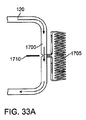
図3A及び3Bは、図2の3A−3A線における送達シャフト7の断面図を示す。1対のチャネル35は、送達シャフトの外表面の近くで、送達シャフト7を通って長手方向に延在する。チャネル35の各々は、チャネル35への外部アクセスを提供するスロット37と通じている。図3Aでは、縫合糸捕捉ロッド15は、各チャネル35内に位置する。スロットは、縫合糸捕捉ロッド15をチャネル35内に確実に包含できるように、寸法及び形状が決められる。図3Bでは、縫合糸捕捉ロッドが近位に引っ張られ、それらによって縫合糸19が引っ張られる。よって、この図は、各チャネル35内に位置した縫合糸19を示している。図3Bに示されるように、スロット37は、(例えば、スロット37を剥がす(peeled out)ことにより)スロット37を通して縫合糸19を除去できるように、縫合糸19より大きくされている。
3A and 3B show a cross-sectional view of the
図4A及び図4Bは、血管の穿刺部を横切る縫合糸ループの位置決めに用いることができる縫合糸送達デバイス5の遠位部の代わりの実施態様の拡大図を示している。同様のデバイスは米国特許第7,004,952号に記載されており、その全体を引用して本明細書に組み込む。図4A及び図4Bは、デバイス5の特徴を図示するために、切り詰められた(truncated)シャフト7から構成された本体を備えたデバイス5を示す。血管壁ロケータは、伸展可能な2つのアーム39の形状をしている。先の実施態様と同様に、血管壁ロケータは、ロッド又は他のカプラ(連結器)を介して、ハンドル9上の動作要素13と連結されてもよい。縫合糸19のループは、縫合糸19の両端部が送達シャフト7の遠位ポート23を出るように、送達シャフト7の中心に位置付けられている。縫合糸19のループの中間25は、送達デバイス5の近位端から外側に出ている。縫合糸ループの各々の端部は、伸展可能なアーム39の各々の端部に取り付けられている。先の実施態様と同様に、デバイスは、ガイドワイヤ33用の中央管腔を備えた遠位チップ21を含んでいる。任意で、遠位チップ21は、先の実施態様で上述したような拡張チップにすることができる。また、先の実施態様と同様に、ガイドワイヤ管腔は、ガイドワイヤが縫合糸送達デバイス5の全長に沿って支えられて(ride)近位端から出ることができるように、又は近位ハンドル9の遠位側にある送達シャフト内のある点から出ることができるように、送達デバイスの全長に沿って延在してもよい。
4A and 4B show enlarged views of an alternative embodiment of the distal portion of the
図4Aは、引き込み位置(retracted position)にある伸展可能なアーム39を備えたデバイスを示している。この構成では、送達デバイス5は、ガイドワイヤを超えて動脈穿刺部内に前進させることができる。デバイスを適所に配置したら、伸展可能なアーム39を外向きに伸展することができ、これは、デバイスを、血管壁に対して正確に位置決めすることを可能にする。図4Bは、伸展位置にあるアーム39を備えたデバイスを示しており、縫合糸ループ19の端部は外側に延在している。縫合糸捕捉ロッド15を伸展して、送達シャフト7が位置している動脈穿刺部の両側の各々まで血管壁を穿刺することができる。縫合糸捕捉ロッド15は、縫合糸ループ19の各端部を捕捉するように構成される。捕捉ロッド15を引き込むと、それらは、縫合糸ループが完全に血管壁内に入って送達シャフト内に縫合糸ループの残りの長さがなくなるまで、血管壁を通り動脈穿刺部を横切って縫合糸ループ19を引っ張る。伸展可能なアーム39は、動脈穿刺部からデバイスを除去可能にするために、引き込ませることができる。
FIG. 4A shows a device with an
使用の方法では、、縫合糸19の端部は、ガイドワイヤ33を適所に維持したまま縫合糸送達デバイス5を除去する間、張力をかけたまま保持される。そして、手技用シース及び拡張器は、ガイドワイヤを超え、予め設置された縫合糸(pre-placed sutures)を通って、血管内に設置される。ガイドワイヤと拡張器が除去され、手技用シースは適所に維持される。縫合糸は、その後の手技中は緩められてもよい。しかしながら、それらは、それらを掴み(grasp)及び張力をかけて保持して、不注意でシースが除去された場合に迅速な止血を達成するように、いくつかの方法によりタグ付けされ(tagged)又はしっかり固定されてもよい。手技の完了後、手技用シースの除去中に、縫合糸は再び張力をかけて保持される。縫合糸の端部が結ばれ、そして、永久止血を達成するために結節が動脈切開部に押し付けられる。
In the method of use, the end of the
図5に示される実施態様では、シース41は、(本願明細書に記載された実施態様の送達デバイスのいずれかであってもよい)縫合糸送達デバイス5に、プレマウント(pre-mounted)される。シース41は、例えば管状体などの細長い本体であり、縫合糸送達デバイス5の送達シャフト7を受け入れる寸法にされた内部管腔を有している。プレマウントシース41は、最初は停めた構成(parked configuration)で位置決めされ、そこでシース41は、送達シャフト7の近位端又は近位領域に配置される。シース41は、縫合糸設置中は停めた構成のまま維持される。縫合糸が動脈切開部を横切って展開した後、縫合糸の端部を捕捉して送達シャフト7から引き剥がす(peeled away)。その後、シース41は、送達デバイス5を超えて動脈切開部内へと、遠位方向にスライドさせることができる。図5は、動脈切開部を横切って縫合糸19を設置した後に前進させたプレマウントシースを示す。その代わりに、プレマウントシース41を前進させる工程は、それが動いて、物理的に縫合糸に接して縫合糸に引き剥がしをもたらしたときに、縫合糸を送達シャフト7からそのプレマウントシース41内へと引き剥がすのを容易にするだろう。プレマウントシースを動脈切開部内に前進させたら、シース41を通して送達デバイス5を除去することができる。
In the embodiment shown in FIG. 5, the
ある実施態様では、プレマウントシース41は、縫合糸送達デバイス5を除去し、その後に、血管内で手技を行うための別の手技用シース(例えば、後述の動脈アクセスシース605など)を挿入する間に、動脈切開部の止血を維持する手段を提供する交換シース(exchange sheath)である。縫合糸が動脈切開を横切って展開したら、交換シース41を、動脈切開部を通して位置付け、次いで縫合糸送達デバイス5を除去する。その後、手技用シースは交換シース41を通って血管内に挿入される。手技用シースを設置したら、交換シース41を除去することができる。ある実施態様では、交換シース41は、引き剥がす方法(peel-away fashion)で手技用シースから除去されるように構成される。プレマウントシース41は、この交換中の出血を防ぐために、その遠位端又はその近位端のいずれかに止血バルブを有していてもよい。止血バルブは、スリット又は交差スリット(cross slit)、又は他の拡張可能な開口を備えた閉止端部(closed end)又はメンブレンの形状にすることができる。メンブレンは通常は閉じており、そこを通る手技用シースの通過を可能にするために開く。
In one embodiment, the
別の実施態様では、プレマウントシース41は、手技中に適所に維持されるアウターシースである。図6に示されるように、アウターシース41は、血管内で寸法を増加して血管を閉塞するのに適した閉塞要素129を含むことができる。プレマウントアウターシース41が血管中に位置付けられると、手技用シースは、アウターシース41を通って血管中に挿入される。そして、手技用シースを用いて、1つ以上の介入デバイスを血管内に導入する。ある実施態様では、手技用シースは、例えば(後述の)シース605などのシースであり、例えば後述する逆流シャントなどの逆流シャントに血管を接続するのに用いられる。シース41上の閉塞要素129は、手技中に血管を閉塞するのに用いられる。血管内の閉塞要素は、膨張式のバルーン、又は拡張可能な部材(例えば、ブレード(braid)、ケージ(cage)など)、又は周囲を密閉用メンブレンで密閉された穴あきチューブ(slotted tube)などにすることができる。アウターシース41はまた、シース保持要素(例えば、膨張可能な構造体、又は拡張可能なワイヤ、ケージ、又は展開されたときに不注意なシース除去を防ぐ関節構造体(articulating structure)など)も含むことができる。
In another embodiment, the
この2重シース構成(dual sheath configuration)により、プレマウントシースを、手技用シースに比べて短くすることができる。手技用シースは、介入デバイスをシースに導入する近位アダプターが血管アクセスサイトから離れたサイトに位置できるように、延長された近位部分を必要としてもよく、それは、血管アクセスサイトが蛍光透視法(fluoroscopy)の領域に近いときに手技に有利であろう。プレマウントシースを比較的短くすることにより、送達シャフト7を短くすることができる。
With this dual sheath configuration, the premount sheath can be shortened compared to the procedure sheath. The procedural sheath may require an extended proximal portion so that the proximal adapter that introduces the interventional device into the sheath can be located at a site remote from the vascular access site, so that the vascular access site is fluoroscopy. The procedure will be advantageous when close to the (fluoroscopy) area. By making the premount sheath relatively short, the
別の実施態様では、プレマウントシース41は手技用シース自身であり、交換シース又はアウターシースの使用を必要としない。手技用シース41は、例えば手技用シースの近位端などに、止血バルブを有していてもよい。これにより、縫合糸送達デバイス5が除去されたときに、止血が維持される。近位延長部を必要とする手技用シース41が用いられる場合、延長部は、縫合糸送達デバイス5の除去後に、手技用シース41の近位端に追加することができる。代わりに、送達シャフト7は、手技用シース及び近位延長部の両方をプレマウントすることのできる伸展長さ(extended length)を有することができる。手技用シース41は、動脈閉塞を必要とする手技のための血管内の閉塞要素を含むことができる。血管内の閉塞要素は、膨張式のバルーン、又は拡張可能な部材(例えば、ブレード、ケージ、又は周囲を密閉用メンブレンで密閉された穴あきチューブ)などにすることができる。手技用シースはまた、シース保持要素(例えば、膨張可能な構造体、又は拡張可能なワイヤ、ケージ、又は展開されたときに不注意なシース除去を防ぐ関節構造体など)も含むことができる。
In another embodiment, the
図1A〜1Cの縫合糸送達デバイス5の典型的な使用方法を以下に記述する。穿刺部は、血管内部へのアクセスを提供するために血管に形成される。血管にアクセスした後、ガイドワイヤが皮膚内から組織を通り組織路(tissue tract)に沿って延在するように、ガイドワイヤを挿入する。縫合糸送達デバイス5は、ガイドワイヤが縫合糸送達デバイス5を組織路に沿って及び動脈切開部を通して血管内に方向付けるように、ガイドワイヤ管腔31(図2)を経てガイドワイヤを超えて前進する。上述のように、送達デバイスの遠位チップは、それが動脈切開部を拡張して入るのを容易にするように、拡張器として働く。送達デバイスの遠位チップは、動脈切開部を拡張する別の拡張器デバイスを用いることなく、動脈切開を拡張するのに利用できる。送達シャフト7は、位置確認管腔を含んでいる。血管壁ロケータ17が血管に入ると、血流は位置確認管腔を通って近位インジケータに流れて、血管壁ロケータが血管に入ったことをオペレーターに知らせる。
An exemplary method of using the
血管壁ロケータ17が血管内部に位置したら、ハンドル9上の動作レバー13を動作させて、血管壁ロケータ17を血管内部の展開位置に動かす。展開された血管壁ロケータ17は、送達シャフト7を引っ張ることにより血管壁ロケータ17を血管壁に対して引き上げることができるように、送達シャフト7から横方向に伸展している。
When the blood
その後、動作ハンドル11を動かして、縫合糸捕捉ロッド15を血管壁ロケータ17に向けて展開する。縫合糸捕捉ロッドは、血管壁ロケータ17の外側端部に含まれている可撓性のリンク29(flexible link)の端部と嵌合する。これは、縫合糸19の少なくとも一端を可撓性リンク29の一端に連結し、そして縫合糸捕捉ロッド15を可撓性リンクの他端に連結する。そして、動脈切開部を横切って縫合糸ループを形成するために、縫合糸捕捉ロッド15を用いて、縫合糸19を伴った可撓性リンクを、血管壁を通して近位方向に引っ張る。その代わりに、縫合糸捕捉ロッド15は、縫合糸19の端部と直接嵌合させてもよく、それらは血管ロケータの外側端部に位置する。そして、動脈切開部を横切って縫合糸ループを形成するために、縫合糸捕捉ロッド15を用いて、縫合糸19の端部を、血管壁を通して引っ張る。次いで、縫合糸捕捉ロッドが縫合糸の端部を皮膚上の組織路外側に引っ張り、その後、そこでユーザーによって回収されるだろう。
Thereafter, the operation handle 11 is moved to deploy the
縫合糸端部に張力をかけて保持して止血を維持しているので、縫合糸送達デバイス5は、ガイドワイヤを超えて除去されて手技用シースと交換される。もし、縫合糸送達デバイス5を手技シースに交換する間に追加の止血制御に必要であれば、用手圧迫は動脈切開サイトに適用することができる。
Since the suture end is held under tension to maintain hemostasis, the
手技の最後は、標準的な経皮的縫合糸クローザーデバイスと同様の方法で、手技シースを除去し、予め設置されていた縫合糸端部を結び、結節を適所に押し込む。縫合糸端部は予め結んでおくことができ、その場合には、単に結節を適所に押し込む。そして、結ばれた縫合糸端部はトリミングされる。 At the end of the procedure, the procedure sheath is removed in a manner similar to a standard percutaneous suture closer device, the pre-installed suture ends are tied, and the knot is pushed into place. The suture ends can be tied in advance, in which case the knot is simply pushed into place. The tied suture ends are trimmed.
この方法の変形例では、上述のように、縫合糸送達デバイス5は動脈に挿入され、そして縫合糸は動脈切開部を横切って設置され、縫合糸の端部を組織路外側及び皮膚上に引っ張り、そこでそれらはユーザーによって回収されるだろう。そして、縫合糸を送達シャフト7から分離する。従来の縫合糸送達デバイスは、縫合糸を送達シャフトから「引き剥がす」ことはできない。その代りに、従来のデバイスでは、縫合糸は送達デバイスの近位端を通って引き抜かれる。本願明細書に開示された送達デバイス5は、縫合糸を送達シャフト7の側面から引き剥がすことを可能にする。上述したように、1つ又は複数の縫合糸捕捉ロッドは、図3A及び3Bに示されるように、送達シャフト7の側面の開いたチャネル(open-sided channels)内に配置される。チャネルは、縫合糸をチャネルから持ち上げる(lifted)又は引き抜く(pulled out)ことができるように、縫合糸に対して寸法が決められる。縫合糸捕捉ロッドは、依然として送達デバイス5の近位端から出ている。縫合糸捕捉ロッドに取り付けられた縫合糸端部は、フック又は予め適用されたループ(pre-applied loop)を用いて送達シャフト7から抜き出され、そして、縫合糸捕捉ロッドから切り離される。縫合糸の他端は、単に側面のチャネル35から引き抜くことができる。先行技術に開示されているように、縫合糸は予め結ばれた結節を有していてもよい。この構成では、結節は、縫合糸端部が回収された後に縫合糸の両端を結節より下側で掴めるように、患者の体外に位置しなければならない。
In a variation of this method, as described above, the
縫合糸が送達デバイス5から離れたら、ガイドワイヤ33を血管内に残したまま、送達デバイス5を血管から取り除くことができる。上述のように、送達デバイスをガイドワイヤから容易に取り除くことができるように、ガイドワイヤチャネルは送達デバイス5を通って完全に延在する。送達デバイス5を除去する前に、プレマウントシース41は、(送達シャフト7の近位端上の)停めた位置(parked position)から、組織路内に及び動脈切開部を通って、遠位方向にスライドさせる。シース41を前方に押す行為は、縫合糸をチャネル35の外側から押し出して(push away)送達シャフト7から押しのける(push away)のを支援することができる。上述のように、プレマウントシースは、交換シース、2重シース構成用のアウターシース、又は手技用シース自身であってもよい。シースはさらに血管内閉塞要素(intravascular occlusion element)を含んでいてもよい。
When the suture leaves the
この構成での変形は、シース41の最終的な方向(ultimate direction)とは反対向きに、縫合糸送達デバイス5を挿入することである。この方法は、例えば、頚動脈狭窄治療の経頚部アクセスにおいて、入れようとしている血管の量に解剖的制約(anatomic restraints)がある場合に、用いることができる。この逆行する送達では、送達デバイスはより垂直的なアプローチ(perpendicular approach)で血管に挿入され、それにより、初期のワイヤ穿刺とそれに続く縫合糸送達デバイスとによって形成された皮膚から動脈への組織路は、反対向きの手技用シースによって動脈にアプローチするのにも用いることができる。縫合糸が展開され、縫合糸端部が回収されると、縫合糸送達デバイスは、ガイドワイヤを適所に維持したまま除去される。その後、ガイドワイヤは、チップ(先端)が反対方向を向くように、再位置決めされる。ガイドワイヤは手技用シースの支援をすることがてきる程度に前進し、次いで手技用シースがガイドワイヤを超えて前進して、血管に挿入される。ガイドワイヤの方向を変更している間に、ガイドワイヤの位置を見失わないことが非常に重要なので、ガイドワイヤに、血管からの除去を防ぐ特徴(feature)(例えば、後述するような拡張可能な要素)を追加してもよい。
A deformation in this configuration is to insert the
ある実施態様では、縫合糸送達デバイス5及びシース41は、頚動脈狭窄治療、脳動脈手術(例えば、急性虚血性脳卒中、脳動脈狭窄、脳動脈瘤の治療など)、又はその他の神経介入性(neurointerventional)の手技に従って、総頚動脈にアクセスするのに用いることができる。ある実施態様では、総頚動脈への経頚部アクセスは、動脈アクセスデバイス110が挿入される皮膚の切開部又は穿刺部を介して、経皮的に達成される。しかしながら、縫合糸送達デバイスの他にも、本願明細書に記述されたいかなるデバイス及び方法もまた、様々な介入手技と共に用いることができる、と認識されるべきである。
In certain embodiments,
別の実施態様では、縫合糸送達デバイスは、拡張チップも、プレマウントシースも有していない。より正確に言えば、縫合糸送達デバイスは、例えば米国特許第7,001,400号に記述されているように構成される。縫合糸送達デバイスは、総頚動脈中で経頚部アクセスを介して行われた動脈切開部を縫合するために用いられる。この実施態様は、図7A及び7Bに示されており、縫合糸送達デバイスは、一般的に、近位端14と遠位端16とを有するシャフト7である。近位ハウジング18は、ニードル動作ハンドル20を支持している。可撓性で、非外傷性の(atraumatic)モノレールガイド体22は、シャフト12の遠位端16の遠位方向に延在する。
In another embodiment, the suture delivery device does not have an expansion tip or a pre-mounted sheath. More precisely, the suture delivery device is configured, for example, as described in US Pat. No. 7,001,400. A suture delivery device is used to suture an arterial incision made via transcervical access in the common carotid artery. This embodiment is illustrated in FIGS. 7A and 7B, where the suture delivery device is generally a
図7Bに示されるように、足部(foot)17は、シャフト12の遠位端の近傍に、関節接合的に(articulatably)取り付けられる。足部17は、近位ハウジング18に配置された足部動作ハンドル26の動作により、(図7Aに図示するように)足部がシャフト12の軸線に沿って実質的に整列しているロープロファイルの構成(low profile configuration)から、足部がシャフトから横方向に伸展している展開位置へと動く。図7A〜7Bに示される縫合糸送達デバイスは、図1A〜1Cの縫合糸送達デバイスが縫合糸を送達するのと同様の方法で、縫合糸を送達する。
As shown in FIG. 7B,
図8は、血管壁及び他の生物組織を縫合するための縫合糸送達デバイスの別の実施態様を示しており、概して符号71で示される。デバイスは、動脈の血管壁Wの縫合に用いられる。デバイス71は、動脈壁Wの開口部Oに挿入するための縫合糸イントロデューサハウジング73を含む。縫合糸クランプアーム75、77の形状をした血管壁ロケータは、挿入中はハウジング内に展開可能に収容され、そして血管内に挿入後に、アームは、図8に示した位置に展開される。展開されると、縫合糸クランプアームは、縫合糸イントロデューサハウジング73の周囲の外側に伸展する。各アームは、縫合糸19をクランプするための少なくとも1つの手段を有し、概して符号78で示され、模式的に図示されている。ニードル89を備えた貫通機構は、概して符号79で示され、血管壁Wへの貫通を提供する。貫通機構は、縫合糸イントロデューサハウジング73又は縫合糸止め具アセンブリ(suture catch assembly)のいずれかの上に提供され、概して符号80で示される。図8に示されるように、貫通機構は、縫合糸止め具アセンブリ80の一部であり、貫通機構はまた、縫合糸19をキャッチし、そしてそれをクランプ手段78から取り外すための縫合糸止め具81を含む。縫合糸止め具アセンブリを作動して、縫合糸止め具によって保持された縫合糸を、血管壁を通して引っ張る。縫合糸の端部が血管の外部に引っ張られた後、イントロデューサハウジングを除去し、縫合糸を結んで血管を閉鎖することができる。
FIG. 8 shows another embodiment of a suture delivery device for suturing blood vessel walls and other biological tissues, generally indicated at 71. The device is used for suturing the arterial vessel
図9に示された実施態様では、縫合糸イントロデューサハウジング73は、内径と外径を、1000分の数インチ〜1000分の数10インチの範囲で、比較的少量だけ異ならせる(vary)ことができるように、一般的には(例えば薄壁の中空状細長円筒部材などの)円柱状で薄壁の皮下注射針(ハイポチューブ:hypo tube)である。ハウジングの外表面42は、縫合糸止め具アセンブリ80の内表面上で、ハウジングをキーと整列させるために、キー溝部82(明瞭にするために誇張されている)を含んでいる(図8)。縫合糸クランプアームを展開するためのアーム動作アセンブリ83は、ハウジングの近位端から突出しており、動作ロッド85は、動作アセンブリからハウジングを通って縫合糸クランプアームまで延びている。図8及び9の縫合糸送達デバイスは、米国特許第5,860,990号及び米国特許第7,004,952号に記載されており、それらの両方の全体を参照して本明細書に組み込む。
In the embodiment shown in FIG. 9, the
図8及び9の縫合糸送達デバイスは、一般に、縫合糸送達デバイス上でアームを第1の位置(アームは縫合糸送達デバイス内にある)から第2の位置(アームは細長い本体から遠ざかるように伸展する)まで動かすことにより、作動する。アームは、縫合糸の一部を保持する。ニードル89の少なくとも1つは、近位側から遠位側へと、少なくとも縫合糸送達デバイスの一部に沿いながらアームに向けて前進し、ニードルは、動脈の組織を通って前進する。ニードルの一部は縫合糸の一部と係合し、そしてニードルは、動脈組織を通して縫合糸を引っ張るために、遠位側から近位側へと引き込まれる。
The suture delivery device of FIGS. 8 and 9 generally moves the arm on the suture delivery device from a first position (the arm is within the suture delivery device) to a second position (the arm is away from the elongated body). It works by moving it to extend). The arm holds a portion of the suture. At least one of the
図10Aは、部分的に展開されて開口87から出ている縫合糸クランプアーム75、77を備えた縫合糸送達デバイスの遠位領域の実施態様の斜視図である。図10Bは、完全に展開された縫合糸クランプアーム75、77を備えた縫合糸送達デバイスの斜視図である。図10Cは、ニードル開口91から伸展して縫合糸クランプアーム75、77に係合している2つ可撓性ニードル89を示している。デバイスは、本願の開示に従って拡張チップを備えるように構成することができる、と認識されるべきであるが、図10A〜10Cのデバイスには拡張チップが示されていない。
FIG. 10A is a perspective view of an embodiment of the distal region of the suture delivery device with
縫合糸19の端部は、ニードル89と係合するように構成されたループ92を備えている。縫合糸クランプアーム75、77の各々は、縫合糸のループ状端部92を保持するための環状凹部93と、縫合糸19の長さのスリット94と、傾斜した端部95とを含む。可撓性ニードル89の各々は、延長シャフトと、貫通遠位チップ96と、遠位チップ96の近傍にある溝97とを含む。ニードル溝97は、戻り止め機構(detent mechanism)又は縫合糸止め具(suture catch)として働く。ある実施態様では、溝97は、ニードル89の全周囲にわたって延在する。他の実施態様では、溝97は、ニードル89の放射状の縁部(radial edge)に沿った周囲の一部である。ループ92は、ニードル89の溝97の直径とほぼ一致しているが、ニードル89の下向きの力に応じて直径方向に拡張するのに十分な弾力がある。
The end of the
縫合糸クランプアーム75、77の一般的な使用方法及び操作方法を記述する。縫合糸19のループ状端部92は、縫合糸クランプアーム75、77の環状凹部93内に設置される。デバイスの遠位端は生物組織に挿入され、そして図10Bに示されるように、縫合糸クランプアーム75、77は半径方向外向きに展開される。貫通可撓性ニードル89は、縫合すべき生物組織(例えば動脈組織)を遠位方向に通過し、そして図10Cに示されるように縫合糸クランプアーム75、77に係合する。
A general method of using and operating the
遠位チップ96が縫合糸19のループ端部92を通過すると、ループ端部92は半径方向外向きに瞬間的に屈曲する。ニードル89が遠位方向に前進すると、ループ端部92は溝97に接する。ループ端部は、半径方向内向きに屈曲してニードル溝97の周りに留まり、それにより、ニードル89を近位方向に引っ張ると、縫合糸端部92がニードル89の近位方向の動きに追従して、縫合糸を動脈組織を通って近位方向に引っ張ることができる。
As the
<追加の実施態様>
別の実施態様では、ガイドワイヤ33は、ガイドワイヤ上にマウントされた少なくとも1つの拡張可能なシール要素43(sealing element)を含んでいる。図11A〜11Cに示した拡張可能な要素43は、例えば、縫合糸送達デバイス5を手技用シースと交換している間及び手技用シースを除去している間などに血管アクセスサイトの止血を維持するために、内部の血管壁に対して拡張することができる。代わりに、縫合糸送達デバイスが縫合糸を組織内に適切に設置できなかった場合、及びデバイスを別の血管クローザーデバイスと交換する必要がある場合に、止血を維持するためにガイドワイヤを用いることができる。第2の血管クローザーデバイスは、別の縫合糸送達デバイスであってもよく、又は別のタイプの血管クローザーデバイスであってもよい。シール要素を備えたこのガイドワイヤは、手技用シースが設けられる前又はシースの除去後に手技を終わる時のいずれかに縫合糸が設置される場合、血管クローザーデバイスを交換するのに用いることができる。
<Additional Embodiment>
In another embodiment, the
拡張可能な要素43は、ガイドワイヤの遠位チップから所定距離だけ近位側に位置することができる。ある実施態様では、拡張可能な要素43は、ガイドワイヤの遠位チップから約3cm近位側に位置する。このことは、ガイドワイヤの遠位チップが、拡張可能な要素43を越えて所定距離だけ挿入されることを保証する。
The
縫合糸送達デバイスが血管に挿入される時、拡張可能な要素は折り畳まなければならない。縫合糸送達デバイス5の拡張チップ21は、血液マーク用のインジケータ管腔45を有していてもよい。よって、オペレーターがガイドワイヤ上の拡張可能な要素43から空気を抜く又は折り畳むことを知ることができるように、送達デバイス5の拡張チップ21が血管に入るとすぐに、表示(indication)がオペレーターに提供される。拡張可能な要素43は、構造的に変更することができる。例えば、拡張可能な要素43は、バルーン、又は拡張可能な部材(例えば、ブレード、ケージなど)、又は周囲を密閉用メンブレンで密閉された穴あきチューブなどにすることができる。
When the suture delivery device is inserted into the blood vessel, the expandable element must fold. The
図11B〜11Cに示されるように、拡張可能なシール要素43は、使用中は血管内部に位置することができる。拡張可能な要素43を血管中に位置付けたら、オペレーターは、拡張可能な要素43が血管内壁をシールするように、近位方向に引き戻すことができる。血管内の動脈圧は、シール要素が血管内壁に力をかけるのにも役立ち、それにより、止血を維持するために(もし必要だとしても)少しの力しか必要としないだろう。図12に示された別の実施態様では、拡張可能な要素43は、血管の外部に位置している。オペレーターは、拡張可能な要素43が血管外壁に圧力をかけて、止血を達成し維持するように、拡張可能な要素で血管外壁を前方に押す。
As shown in FIGS. 11B-11C, the
さらに別の実施態様では、図13に示されるように、ガイドワイヤは1対の拡張可能なシール要素43a、43bを含んでいる。使用中に、血管壁は拡張可能な要素43a、43bの間に置かれ、拡張可能な要素43が血管壁に圧力をかける。これは有利なことに、血管壁に対する相対的な動きに対抗して、ガイドワイヤの位置をロックする。拡張可能な要素43a、43bは、血管壁にかける圧力を達成するために、互いに向けてバネ付勢(spring-loaded)されていてもよい。複数の拡張可能な要素(multi-expandable element)の実施態様の変形例では、拡張可能な要素43は膨張式のバルーンである。これを動脈切開部の「前拡張」に用いるつもりがない場合を除いて、拡張可能な部分は使用中に動脈切開部のサイズを増加させないことに留意すべきである。
In yet another embodiment, the guidewire includes a pair of
別の実施態様では、ガイドワイヤは、血管中に送達デバイス5及び/又は手技用シースを挿入する間に、血管に対するガイドワイヤの相対的な位置を維持する血管内アンカーを含んでいる。図14に示されるように、アンカー47は、例えば、膨張式のバルーン、拡張可能なケージ又はブレード、又は血管内壁に固定される他の要素にすることができる。拡張可能又は膨張可能なアンカー47の場合、アンカー47は、アンカー47が血管壁に十分な力を及ぼして、アンカー47を適所に固定できるような寸法に拡張する。
In another embodiment, the guidewire includes an intravascular anchor that maintains the relative position of the guidewire relative to the blood vessel during insertion of the
ある実施態様では、拡張可能な要素は、拡張可能なシール要素と血管内アンカーの両方として役立つことができる。例えば、拡張可能な要素がバルーンであった場合、ある直径での膨張は、ガイドワイヤを血管内にアンカーさせるだけでなく、動脈切開部の周りにシールを作成するのにも十分かもしれない。代わりに、拡張可能な要素は、動脈切開部をシールするために、ある直径まで膨張し、そして血管壁にアンカーさせるために、より大きい直径まで膨張する。同様に、機械的に拡張可能な要素は、シールとアンカーの両方のために拡張してもよく、又は、シールを十分に形成するためにある状態まで拡張し、血管壁にアンカーするためにより大きく拡張してもよい。デバイスは、シールのための拡張状態とアンカーのための拡張状態との間で、再位置決めを必要としてもよい。 In certain embodiments, the expandable element can serve as both an expandable sealing element and an endovascular anchor. For example, if the expandable element was a balloon, expansion at a certain diameter may be sufficient to create a seal around the arteriotomy as well as anchor the guidewire into the blood vessel. Instead, the expandable element expands to a certain diameter to seal the arteriotomy and expands to a larger diameter to anchor the vessel wall. Similarly, a mechanically expandable element may be expanded for both seals and anchors, or larger to expand to some state and anchor to the vessel wall to fully form the seal. It may be expanded. The device may require repositioning between an expanded state for the seal and an expanded state for the anchor.
図15は、別の実施態様を示しており、ガイドワイヤ33は、ガイドワイヤを適所に保持するために患者の皮膚に固定することのできる1つ以上のクリップ51に付着している。クリップ51は、粘着性の基材(backing)を含む様々な手段を用いて、患者に固定することができる。クリップ51は、様々な構成で、患者の皮膚上に位置することができる。図15の実施態様では、皮膚内への侵入位置の近傍にある1つのクリップ51aと、エントリー位置から離れた別のクリップ51bとを含む2つのクリップ51が用いられている。クリップ51は、ガイドワイヤを常に適所に保持する役目をする。クリップ51bは、送達デバイス5がワイヤに積載(load)されたら開放され、そして送達デバイス5が皮膚に挿入されて血管内に位置付けられたら再びクリップされて、クリップ51aが開放されてもよい。同様に、クリップは、送達デバイスが除去されている間、及び手技用シースが血管内に挿入されている間に、ガイドワイヤ33の位置を維持するのに用いることができる。
FIG. 15 illustrates another embodiment, where the
クリップ51は、封鎖縫合糸19の処理に用いることもできる。クリップ51は、1つ以上のアタッチメント手段(例えばスロット)を含むことができ、その中に、縫合糸を挿入して保持することができる。図16及び17は、縫合糸が予め結ばれていない例(図16)と、縫合糸が予め結ばれている例(図17)を示す。複数の縫合糸は、両方ともクリップ51の同じ側に設置することができる。クリップ51は、例えば、手技用シースを設置できるまで止血を維持するために縫合糸に張力をかけて維持して止血する必要がある時間の間、縫合糸に張力をかけて保持できるように構成されてもよい。この場合、結節が予め作られても又は作られなくても、それが皮膚の外側にあり且つ縫合の両側を張力をかけて保持するのに十分な程度にずっと離すことができる。縫合糸は、手で、又は皮膚上のクリップ又はクリート(cleat)で、張力をかけて保持することができる。縫合糸の後端部は、タグ又はハンドルに取り付けるか、又は、このプロセスをより簡単にするために、後で皮膚に固定するクリップ又はクリートに予め取り付ける(preattached)ことができる。縫合糸は、介入中にはこのクリップ又はクリートの中に保持することも、それらが邪魔をしている(in the way)場合には除去して、シースの除去後で結節を結ぶ前に再挿入することもできる。あるいは、縫合糸は手で張力をかけて保持して、その直後に結節を結ぶこともできる。あるいは、結節が予め結ばれている場合、結節は、単に適所まで押し下げることもできる。
The clip 51 can also be used for processing the sealing
図18A〜18Cに示されている別の実施態様では、自動閉鎖材料(self-closing material)53は、送達シャフト7の近位領域に予め積載されている。穴部は自動閉鎖材料の中心を通って延在し、送達シャフト7は穴部を通って位置付けられる。自動閉鎖材料は、送達デバイス5が穴部から引き抜かれたときに、穴部を覆って自動的に閉鎖するように構成される。自動閉鎖材料は、穴、スリット、交差スリット、ダックビルバルブ(duck-bill valve)を備えたゴム製のプラグ又はメンブレン、又は例えばスポンジ(foam)などの圧縮可能な材料、又はデバイス5を引き抜いたときに動脈切開部の上を閉鎖する単純な1対のバネ部材(例えばワイヤ又は板ばねなど)にすることができる。自動閉鎖材料はまた、コラーゲンプラグ、生体吸収性ポリマー、非生体吸収性ポリマー(例えばダクロン(Dacron)又はePTFEなど)、又は他の適切な医療用材料にすることもできる。自動閉鎖材料が一時的なものの場合、材料は、例えばシリコーンゴム、又はポリウレタンなどの柔軟なエラストマーにすることができる。
In another embodiment shown in FIGS. 18A-18C, a self-closing
図18Aに示されるように、動脈切開部から送達デバイス5を取り除く直前に、自動閉鎖材料は、例えばプッシング要素(pushing element)55(例えばプッシュロッド(push rod)又はチューブなど)などにより、動脈切開部を覆って遠位方向に押される。プッシング要素55は、送達デバイス5と一体にされていて、又は別の付属アイテムであってもよい。図18Bに示されるように、自動閉鎖材料は、止血を維持するために動脈切開部上に圧迫状態で保持される。適所に維持されたガイドワイヤだけでなく、ちょうど設置された縫合糸19も、自動閉鎖材料の中央開口部を通過する。その後、図18Cに示されるように、手技用シースは、ガイドワイヤを超え、自動閉鎖材料を通り、動脈切開部を通り、血管内に位置決めされる。その後に、自動閉鎖材料を血管外壁に圧迫状態で保持するプッシャ(pusher)を、緩めることができる。手技が終わった後、プッシャは、結節が縫合糸で結ばれるまで動脈切開部を圧迫するために、再び押すことができる。プッシャが固いスリーブの場合、組織路を介したデバイスの交換を容易にするために、チャネルを提供する手段としてプッシャを2重にすることができる。
As shown in FIG. 18A, just before the
この実施態様の変形例では、自動閉鎖材料は、手技が終わった時に適所に残されて、止血材料として働く。材料は、送達シャフトに予め積載されており、縫合糸捕捉ロッドは、送達シャフトの各側面までの場所に挿通される。このように、縫合糸が送達シャフトから引き抜かれると、それらも自動閉鎖材料の2つの側面穴を通って引っ張られる。上記のように、材料は適所に押し込まれ、デバイス交換中に一時的な止血剤として働く。しかしながら、手技が終わった時に、縫合糸端部が永久止血を達成するために結ばれる場合には、材料は適所に残される。 In a variation of this embodiment, the self-closing material is left in place when the procedure is over and acts as a hemostatic material. The material is preloaded on the delivery shaft, and the suture capture rod is inserted through to the sides of the delivery shaft. Thus, when sutures are withdrawn from the delivery shaft, they are also pulled through the two side holes in the self-closing material. As mentioned above, the material is pushed into place and acts as a temporary hemostatic agent during device replacement. However, when the procedure is finished, the material is left in place if the suture ends are tied to achieve permanent hemostasis.
図19A〜19Cに示されている別の実施態様では、止血材料57は、手技用シースの除去後に動脈切開部の場所上に位置付けられる。止血材料57は、縫合糸結節を結ぶ前、又は縫合糸結節を結んでいる間に、縫合糸19を覆って設置される。結節は、動脈切開部上の適所に止血材料を固定する。代わりに、止血材料は、縫合糸結節を結んだ後に動脈切開部上に挿入され、そして、止血材料を動脈切開部に保持するために、別の結び又はクリップのいずれかを用いることができる。自動閉鎖材料は、例えば、コラーゲンプラグ、生体吸収性ポリマー、非生体吸収性ポリマー(例えばダクロン(Dacron)又はePTFEなど)、又は他の適切な医療用材料にすることもできる。止血材料は、一時的な又は永久的な材料にすることができる。特許第5,549,633号は、縫合糸にシーリング材を連結するための典型的なデバイス及び方法について記述されており、その全体を参照して本明細書に組み込む。
In another embodiment shown in FIGS. 19A-19C, the
<逆流システム>
上記の縫合糸クローザーデバイスの実施態様は、様々な介入手技と共に用いられる逆流システムと組み合わせて用いることができる。逆流システムの典型的な実施態様と典型的な介入手技を記述する。このシステムは、頚動脈ステント留置術に限定されずに様々な手技と共に用いることができることが認識されるべきであるが、このシステムは、時々、頚動脈ステント留置術と共に用いる文脈(context)で記載されている。
<Backflow system>
The embodiments of the suture closer device described above can be used in combination with a reflux system used with various interventional techniques. An exemplary embodiment of a backflow system and typical interventional techniques are described. It should be appreciated that this system can be used with a variety of procedures without being limited to carotid stenting, but this system is sometimes described in the context used with carotid stenting. Yes.
図20は、逆流システム100の第1の実施態様を示しており、このシステムは、脳血管(特に内頚動脈)への塞栓の放出を制限又は防止するために、頚動脈分岐部の領域内における逆流血液循環(retrograde or reverse flow blood circulation)を確立し促進するのに適している。システム100は、頚動脈と相互に作用して、頚動脈から、例えば内頚静脈(又は、別の大静脈や、代わりの実施態様における外部レセプタクルなどの別のリターンサイト)などの静脈リターンサイトに逆流を提供する。逆流システム100は、動脈アクセスデバイス110と、静脈リターンデバイス115と、動脈アクセスデバイス110から静脈リターンデバイス115までの逆流通路を提供するシャント120と、を含んでいる。血流制御アセンブリ125はシャント120と相互に作用する。以下により詳細に記述するように、血流制御アセンブリ125は、総頚動脈から内頚静脈までの逆流を調節し及び/又はモニタするのに適している。血流制御アセンブリ125は、シャント120、内部の血流パス及び外部の血流パスのいずれか一方又は両方を介して血流パスと相互に作用する。
FIG. 20 shows a first embodiment of the
より詳細に後述されるように、動脈アクセスデバイス110は少なくとも部分的に、総頚動脈CCAに挿入され、静脈リターンデバイス115は少なくとも部分的に、内頚静脈IJVなどの静脈リターンサイトに挿入される。動脈アクセスデバイス110及び静脈リターンデバイス115は、結合位置127a、127bにおいて、シャント120と結合される。総頚動脈を通る血流が遮断される場合、内頚動脈と静脈系との間の自然な圧力勾配によって、血液は、脳血管から内頚動脈とシャント120とを通って静脈系まで、逆方向RGに流れる。血流制御アセンブリ125は、逆流する血流を調整し(modulate)、増大させ(augment)、支援し(assist)、モニタし(monitor)、及び/又は別の方法で調節する(regulate)。
As will be described in more detail below, the
図20の実施態様では、動脈アクセスデバイス110は、経頚部アプローチを介して総頚動脈CCAにアクセスする。経頚部アクセスは、血管アクセスポイントから目標の処置位置までの距離が短く且つねじ曲がっていない経路を提供し、それにより、例えば経大腿部アプローチと比較して、手技にかかる時間及び困難性を緩和する。さらに、このアクセスルートは、疾患があり、角張っており、あるいはねじ曲がっている大動脈弓又は総頚動脈組織を航海することによる塞栓発生のリスクを低減する。少なくとも静脈リターンデバイス115の一部は、内頚静脈IJVに設置される。ある実施態様では、総頚動脈への経頚部アクセスは、動脈アクセスデバイス110が挿入される皮膚の切開又は穿刺を介して、経皮的に達成される。もし切開が用いられる場合、切開の長さを約0.5cmにすることができる。拡張可能なバルーンなどの閉塞要素129は、動脈アクセスデバイス110の遠位端の近位側の位置で総頚動脈CCAを閉塞するのに用いることができる。閉塞要素129は、動脈アクセスデバイス110に配置することができ、又は別のデバイスに配置することができる。代わりの実施態様では、動脈アクセスデバイス110は、直接的な外科的経頚部アプローチ(direct surgical transcervical approach)を介して総頚動脈CCAにアクセスする。外科的アプローチでは、総頚動脈は止血器2105を用いて閉塞することができる。任意の外科的アプローチで用いられるデバイスであることを示すために、止血器2105は2点鎖線(phantom)で図示される。
In the embodiment of FIG. 20,
別の実施態様では、動脈アクセスデバイス110は経頚部アプローチを介して総頚動脈CCAにアクセスし、その一方、静脈リターンデバイス115は、頚静脈以外の静脈リターンサイト(例えば大腿静脈FVから構成された静脈リターンサイトなど)にアクセスする。静脈リターンデバイス115は、鼠径部の経皮的穿刺を介して大腿静脈FVなどの中心静脈に挿入することができる。
In another embodiment, the
別の実施態様によれば、動脈アクセスデバイス110は、大腿部アプローチを介して総頚動脈にアクセスする。大腿部アプローチによれば、動脈アクセスデバイス110は、例えば鼠径部内の大腿動脈FAへの経皮的穿刺を介して、大動脈弓AAを上がって目標となる総頚動脈CCAへと、総頚動脈(CCA)にアプローチする。静脈リターンデバイス115は、頚静脈JV又は大腿静脈FVと通じることができる。
According to another embodiment, the
別の実施態様によれば、システムは、頚動脈から、(静脈リターンサイトではなく)外部レセプタクル130へと向かう逆流を提供する。動脈アクセスデバイス110は、シャント120を介してレセプタクル130に接続しており、シャント120は血流制御アセンブリ125と通じている。逆流した血液は、レセプタクル130に回収される。必要に応じて、血液をろ過し、次いで患者に戻すことができる。レセプタクル130の圧力は、ゼロプレッシャー(大気圧)又はそれ以下に設定してもよく、それにより脳血管からレセプタクル130への逆方向の血液の流れがもたらされる。任意で、内頚動脈からの逆流を達成又は高めるために、典型的には、外部頚動脈中のうちで内頚動脈との分岐部の直上に、バルーン又は他の閉塞要素を展開することにより、外頚動脈からの血流を遮断してもよい。
According to another embodiment, the system provides a backflow from the carotid artery toward the external receptacle 130 (rather than the venous return site).
<逆流する血流システム(RETROGRADE BLOOD FLOW SYSTEM)の詳述>
先に述べたように、逆流システム100は、動脈アクセスデバイス110と、静脈リターンデバイス115と、動脈アクセスデバイス110から静脈リターンデバイス115への逆流のための通路を提供するシャント120と、を含んでいる。システムはまた、血流制御アセンブリ125を含んでおり、それはシャント120と相互に作用して、シャント120を介して逆流する血流を調節し及び/又はモニタする。逆流システム100の構成要素の典型的な実施態様を、ここに記述する。
<Details of RETROGRADE BLOOD FLOW SYSTEM>
As previously mentioned, the
<動脈アクセスデバイス>
図21Aは、動脈アクセスデバイス110の典型的な実施態様を示しており、遠位シース605、近位延長部610、血流ライン615、アダプター又はYコネクタ620、及び止血バルブ625を含む。遠位シース605は、開放外科的切開、又は、例えばセルジンガー法を用いて確立された経皮的穿刺のいずれかによる総頚動脈の壁部への切開又は穿刺を通して導入するのに適している。シースの長さは5〜15cmの範囲にすることができ、通常は10cm〜12cmである。内径は、典型的には7Fr(フレンチ:1Fr=0.33mm)〜10Frの範囲にあり、通常は8Frである。特に、シースが経頚部アプローチを介して、鎖骨より上側だが頚動脈の分岐部より下側に導入される場合、シース605は、よじれ(kinking)と曲がり(backling)に抵抗するためのフープ強度(hoop strength)を保持しつつ、非常に柔軟であるのが望ましい。このように、遠位シース605は、組み紐(braid)、螺旋状のリボン(helical ribbon)、螺旋状のケーブル(helical wire)などによって、周囲から強化されてもよい。代わりの実施態様では、遠位シースは、例えば鼠径部内の大腿動脈への経皮的穿刺を介して、大動脈弓AAを上がって目標となる総頚動脈CCAへと導入するのに適している。
<Arterial access device>
FIG. 21A shows an exemplary embodiment of an
図21B(シース605の遠位領域630の拡大図を示している)に示すように、遠位シース605は、縮径された遠位領域630を有している階段状(stepped)又は他の形態を有することができる。シースの遠位領域630は、頚動脈への挿入に適したサイズにされていて、内径は典型的には2.16mm(0.085インチ)〜2.92mm(0.115インチ)の範囲であり、シースの残りの近位領域は、より大きい外径と内腔径(luminal diameters)にされていて、内径は典型的には2.794mm(0.110インチ)〜3.43mm(0.135インチ)の範囲である。近位領域のより大きな内腔径は、シースの全体的な血流抵抗を最小にする。ある実施態様では、縮径された遠位部分630の長さはおよそ2cm〜4cmである。縮径された遠位部分630の比較的短い長さによって、シース605の遠位端が分岐部Bと接触するリスクを低減しながら、この部分が経頚部アプローチを介して総頚動脈CCAに位置することを可能にする。さらに、縮径された部分630はまた、血流抵抗のレベルにわずかな影響しか及ぼさずに、動脈にシース605を導入するための動脈切開(arteriotomy)のサイズを縮小することを可能にする。
As shown in FIG. 21B (showing an enlarged view of the
図21Aを再び参照すると、近位延長部610は、シース605の内腔に接触した(contiguous with)内腔を有している。それらの管腔は、血流ライン615の管腔もシースに接続するYコネクタ620によって連結することができる。アセンブリシステムでは、血流ライン615は、逆流シャント120の第1の脚部(leg)に接続されて、それを形成する。近位延長部610は、止血バルブ625をYコネクタ620から間隔を置くのに十分な長さを有することができ、Yコネクタ620は経皮的又は外科的な挿入サイトに隣接している。止血バルブ625を経皮的挿入サイトから遠ざけて間隔を置くことによって、蛍光透視法(fluoroscopy)が行われているときに、医師は、ステント送達システム又は他の作動カテーテルを、蛍光透視法の視野外にとどまらせながら、近位延長部610及びシース605に導入することができる。
Referring again to FIG. 21A, the
洗い流しライン(flush line)635は、止血バルブ625側に接続することができ、近位端又は遠位端に栓640を有することができる。洗い流しライン635は、手術中に、食塩水、造影剤(contrast fluid)などの導入を可能にする。洗い流しライン635はまた、手術中に圧力をモニタすることを可能にするだろう。先細の遠位端650を有する拡張器(dilator)645を提供して、総頚動脈への遠位シース605の導入を容易にすることができる。図22Aに最もよく見られるように、先細の遠位端650がシース605の遠位端を通って延在するように、拡張器645は止血バルブ625を通って導入することができる。拡張器645は、ガイドワイヤを収容するために、中央の管腔を有することができる。典型的には、ガイドワイヤが最初に血管に設置され、そして拡張器/シースの組合せがガイドワイヤの上を移動して、血管に導入される。
A
やはり図22Aで見られるように、任意で、遠位シース605の外部に同軸で受容されるチューブ705を備えてもよい。チューブ705は、アダプター620を係合させるフレア状(flared:裾広がり)の近位端710と、遠位端715と、を有する。図22Bに示すように、任意で、遠位端715を斜めにしてもよい。チューブ705は、少なくとも2つの目的のために役立つだろう。第1に、図22Aに見られるように、チューブ705の長さによって、シース605の導入は、シース605の露出した遠位部分に制限される。第2に、チューブ705は頚動脈壁に配置される予備展開穿刺クローザーデバイス(pre-deployed puncture closure device)と係合することができ、もし存在するなら、閉止デバイスを取り除かずに、シース605を引き抜くことを可能にする。
As also seen in FIG. 22A, an optional tube 705 may be provided that is coaxially received outside the
遠位シース605は、およそ総頚動脈上の前後方向のアプローチ(anterior-posterior approach)から、およそ総頚動脈内の管腔の軸方向へと、曲線の変化を確立するように構成することができる。経皮的アクセスが総頚動脈壁を通って提供される場合、方向の変化は特に有用である。切開による外科的アクセスは、総頚動脈の管腔内の直線シースと角度をなすいくらかの距離を許容する一方、経皮的アクセスは、一般に管腔のアクセスに対して垂直又は直角の方向であり、そのような場合、斜めに屈曲(flex)又は回転(turn)できるシースは、有益な利用法を見いだすだろう。
The
ある実施態様では、シース605は、シース605を挿入した血管(例えば総頚動脈)内にシースを保持するのに適した保持用の特徴(a retention feature)を含んでいる。保持用の特徴は、シース605が血管から不注意に引き抜かれる可能性を低減させる。この点において、保持用の特徴は血管と相互作用して、望ましくない引き抜きに抵抗及び/又は引き抜きを排除する。さらに、保持用の特徴はまた、血管壁と相互作用する追加の要素も含んで、シースが血管中に深く入り過ぎるのを防ぐこともできる。保持用の特徴はまた、動脈血圧に対抗してシースを穿刺位置で密閉するのに役立つシール要素を含むこともできる。
In certain embodiments, the
シース605は、様々な方法で形成できる。例えば、シース605は、先端から所定の距離(典型的には2〜3cm)に、湾曲部又は角部を持つようにプレシェイプする(pre-shaped:あらかじめ形づくる)ことができる。プレシェイプされた湾曲部又は角部は、典型的には20°〜90°の範囲、好ましくは30°〜70°の範囲の曲げを提供する。導入初期には、シース605は、その管腔に設置される拡張器645などの閉鎖器具又は他の直線状又は成形された器具によって、真っ直ぐにされるだろう。シース605が、経皮的又は他の動脈壁貫通を通して少なくとも部分的に導入された後、閉鎖物(obturator)を引き抜いて、シース605が動脈管腔内でそのプレシェイプの形態を再び取り戻すことを可能にする。
The
他のシース構造は、シースを設置できるようなわたみ機構(deflection mechanism)を持つことを含んでおり、カテーテルは、その位置で所望の展開角度にたわむことができる。さらに別の構造では、カテーテルは、総頚動脈の管腔内に設置したときに、硬くない構造(non-rigid configuration)を有する。管腔内に設置した後、シースを望ましい構造に形作る又は硬直させるために、プルワイヤ(pull wire)又は他の硬直機構(stiffening mechanism)を展開することができる。そのような機構の1つの具体例は、医学及び特許の文献によく記載されている「形状ロック」機構("shape-lock" mechanisms)として一般に知られている。 Other sheath structures include having a deflection mechanism that allows the sheath to be placed so that the catheter can be deflected to the desired deployment angle at that location. In yet another structure, the catheter has a non-rigid configuration when placed in the lumen of the common carotid artery. After placement in the lumen, a pull wire or other stiffening mechanism can be deployed to shape or stiffen the sheath into the desired structure. One specific example of such a mechanism is commonly known as "shape-lock" mechanisms, which are well described in the medical and patent literature.
別のシース構造は、直線で柔軟なシースに挿入される湾曲した拡張器を含み、拡張器とシースは、挿入中に湾曲する。シースは、拡張器を除去した後に、組織に適合するように十分に柔軟である。 Another sheath structure includes a curved dilator that is inserted into a straight and flexible sheath, where the dilator and the sheath are curved during insertion. The sheath is sufficiently flexible to fit the tissue after removing the dilator.
ある実施態様では、シースは、固有の(built-in) 穿刺能力と、ガイドワイヤの先端と類似した無傷性の先端(atraumatic tip)とを有している。これにより、微小穿刺技術による動脈アクセスで現在用いられているニードル及びワイヤ交換の必要をなくし、よって、時間を節約し、失血を低減し、そして高い外科的スキルを必要としないようにできる。 In some embodiments, the sheath has a built-in piercing capability and an atraumatic tip similar to the guidewire tip. This eliminates the need for needle and wire replacement currently used in arterial access with micropuncture techniques, thus saving time, reducing blood loss, and not requiring high surgical skills.
図23Aは、動脈アクセスデバイス110の別の実施態様を示す。この実施態様は、遠位シース605が、例えば総頚動脈を通る血流を閉塞するための閉塞要素129を含んでいる以外は、図21Aに示された実施態様と実質的に同様である。閉塞要素129がバルーンなどの膨張式の構造体である場合、シース605は、閉塞要素129と通じている膨張用管腔(inflation lumen)を含むことができる。閉塞要素129は、膨張式のバルーンにすることができるが、膨張式のカフ(cuff)や、総頚動脈の内壁に係合してそこを通過する血流を遮断するための外向きに裾が広がった円錐状又は他の円周要素や、膜で覆われた組み紐や、軸方向に圧縮されたときに半径方向に拡大する穴あきチューブ(slotted tube)や、又は機械的手段等によって展開できる同様の構造体にすることもできる。バルーン閉塞の場合、バルーンは、適合した(compliant)、不適合の(non-compliant)、弾性の(elastomeric)、強化された(reinforced)、又は様々な他の特徴を持っている。ある実施態様では、バルーンは、膨張する前はシースの遠位端の外側を覆って密着して受容されている弾性バルーンである。膨張したときは、弾性バルーンは、総頚動脈の内部壁を拡張し、内部壁に適合することができる。ある実施態様では、弾性バルーンは、非展開の形態に比べて少なくとも2倍の直径に拡張することができ、しばしば、非展開の形態に比べて少なくとも3倍の直径に拡張することができ、より好ましくは、非展開の形態に比べて少なくとも4倍の直径、又はそれ以上に拡張することができる。
FIG. 23A shows another embodiment of the
図23Bに示すように、閉塞要素129を備えた遠位シース605は、縮径された遠位領域630を有している階段状(stepped)又は他の形態を有することができる。遠位領域630は、頚動脈への挿入に適したサイズにされており、シース605の残りの近位領域はより大きい外径と内腔径にされていて、内径は典型的には2.794mm(0.110インチ)〜3.43mm(0.135インチ)の範囲である。近位領域のより大きな内腔径は、シースの全体的な血流抵抗を最小にする。ある実施態様では、縮径された遠位部分630の長さはおよそ2cm〜4cmである。縮径された遠位部分630の比較的短い長さによって、シース605の遠位端が分岐部Bと接触するリスクを低減しながら、この部分が経頚部アプローチを介して総頚動脈CCAに位置することを可能にする。
As shown in FIG. 23B, the
図24及び25に示される実施態様では、近位延長部610は接続位置でYアームコネクタ620と着脱可能に接続される。この実施態様では、近位延長部が取り付けられていない場合に止血が維持されるように、近位延長部610のYアームコネクタ620との接続サイトに、追加の止血バルブ621を含むことができる。図24は、Yコネクタ620に取り付けられた近位延長部610を備えた動脈アクセスシース605を示す。図24はまた、閉塞要素129のバルーンを膨張するための追加の接続ライン623も示している。図25は、Yコネクタ620から除去された近位延長部610を示す。
In the embodiment shown in FIGS. 24 and 25, the
<静脈リターンデバイス>
次に図26を参照すると、静脈リターンデバイス115は、遠位シース910及び血流ライン915を含むことができ、システムの使用中は、シャント120に接続されてシャント120の脚部を形成する。遠位シース910は、切開又は穿刺を通して静脈リターン場所(頚静脈又は大腿静脈など)に導入するのに適している。遠位シース910及び血流ライン915は永久に取り付けることができ、又は、図26に示すように、従来のluer嵌合を用いて取り付けることができる。任意で、図27に示すように、シース910はYコネクタ1005によって血流ライン915に結合することができる。Yコネクタ1005は、拡張器1015の挿入を可能にする止血バルブ1010を含むことができ、内頚静脈又は他の静脈への静脈リターンデバイスの導入を容易にする。動脈アクセス拡張器645と同様に、静脈拡張器1015はガイドワイヤ用の中央の管腔を含んでおり、それにより、静脈シースと拡張器との組合せをガイドワイヤ上に設置できる。任意で、静脈シース910は、近位端又は遠位端に栓1025を備えた洗い流しライン1020を含むことができる。
<Venous return device>
Referring now to FIG. 26, the
システム全体の血流抵抗を低減するために、動脈アクセス血流ライン615及び静脈リターン血流ライン915、並びにYコネクタ620、1005の各々は、比較的大きい血流の管腔内部径で、典型的には2.54mm(0.100インチ)〜5.08mm(0.200インチ)の範囲の内部径と、比較的短い長さで、典型的には10cm〜20cmの範囲の長さとを持つことができる。システム血流抵抗は低いのが望ましく、それは、塞栓のリスクが最大になったときに、手技の一時期の間に血流を最大にすることを可能にできるからである。以下に詳細に説明するように、低いシステム血流抵抗はまた、システム中の血流を制御するための可変血流抵抗の使用を可能にする。静脈リターンシース910の寸法は、上記した動脈のアクセスシース605の寸法と、およそ同じである。静脈リターンシース内に、止血バルブ1010用の延長部は必要ではない。
To reduce overall system blood flow resistance, each of arterial access
<逆流シャント(Retrograde Shunt)>
シャント120は、動脈アクセスカテーテル110と静脈リターンカテーテル115との間の流体の連絡を提供してそれらの間で逆流する血流の経路を提供する単一チューブ又は複数の接続チューブから形成することができる。シャント120は、その一端で、(コネクタ127aを介して)動脈アクセスデバイス110の血流ライン615に接続し、他端で、(コネクタ127bを介して)静脈リターンカテーテル115の血流ライン915に接続する。
<Retrograde Shunt>
The
ある実施態様では、シャント120は、血流制御アセンブリ125と通じる少なくとも1本のチューブで形成することができる。シャント120は、血流用の流体経路を提供するどのような構造体でもよい。シャント120は、単一の管腔を持つことができ、又は複数の管腔を持つことができる。シャント120は、血流制御アセンブリ125、動脈アクセスデバイス110及び/又は静脈リターンデバイス115に、取り外し可能に取り付けられてもよい。使用前に、ユーザーは、動脈アクセス場所及び静脈リターン場所に使用するのに最適な長さのシャント120を選択することができる。ある実施態様では、シャント120は、シャント120の長さを変更するのに利用できる1本以上の延長チューブを含んでいてもよい。延長チューブは、所望の長さを達成するために、シャント120にモジュールで取り付けることができる。シャント120のモジュール態様は、ユーザーが、必要に応じて、静脈リターンサイトに依存してシャント120を延長するのを可能にする。例えば、何人かの患者では、内頚静脈IJVは小さく、及び/又はねじ曲がっている。他の組織構造体に近いので、この位置での合併症のリスクは他の場所よりも高いかもしれない。さらに、頚部の血腫は、気道閉塞及び/又は脳血管の合併症を引き起こすかもしれない。従って、そのような患者にとって、内頚静脈IJV以外の位置、例えば大腿静脈などに静脈リターンサイトを配置のが望ましいだろう。大腿静脈リターンサイトは、重大な合併症の低いリスクと共に経皮的に達成されてもよく、そして、内頚静脈IJVが利用可能でない場合には、中心静脈に代わりの静脈アクセスを提供する。更に、大腿部静脈リターンは、デバイスが導入され造影剤射出ポートが配置される介入の「作業領域(working area)」に近接してシャント制御が配置されるように、逆流シャントのレイアウトを変更する。
In certain embodiments, the
ある実施態様では、シャント120は、内径が4.76mm(3/16インチ)で、長さが40〜70cmである。上述のように、シャントの長さは調節することができる。
In one embodiment, the
<血流制御アセンブリ---逆流の調節とモニタリング>
血流制御アセンブリ125は、シャント120と相互に作用して、総頚動脈から、例えば内頚静脈などの静脈リターンサイトへの、又は外部レセプタクル130への逆流速度を調節及び/又はモニタする。これに関して、ユーザーは、血流制御アセンブリ125により、現存のシステムより高い最大血流速度を達成することができ、また、逆流する血流速度を選択的に調節、設定、又は調整することができる。以下に全て記載するように、様々な機構を利用して、逆流速度を調節することができる。以下に記載するように、ユーザーは、血流制御アセンブリ125により、様々な処置法に適したやり方で逆流する血流を構成することができる。
<Blood flow control assembly --- regulation and monitoring of backflow>
The blood
一般的に、連続的な逆流速度を制御する能力は、医師が個々の患者及び手術のステージのためにプロトコルを調節することを可能にする。逆流する血流速度は、典型的には、低速〜高速の範囲にわたって制御されるだろう。高速は、低速に比べて少なくとも2倍速く、典型的には低速に比べて少なくとも3倍速く、また多くの場合低速に比べて少なくとも5倍又はそれ以上速い。ある実施態様では、高速は、低速より少なくとも3倍速く、また別の実施態様では、高速は低速より少なくとも6倍速い。逆流する血流速度を高くして、頚動脈からの塞栓の抽出を最大にするのが一般的に望ましいが、患者が逆流する血流を許容する能力は変化するだろう。このように、逆流する血流速度を容易に調整できるシステム及びプロトコルを有することにより、血流速度がその患者にとって耐えられるレベルを越えているときは、治療する医師が決定して、それに応じて逆流速度を設定することができる。連続的な高速の逆流速度を許容できない患者には、医師は、塞栓のデブリスのリスクが最も高く、手技で危険な短い間だけ、高速の血流を作動させることを選択できる。短い間隔、例えば15秒〜1分であれば、患者の耐性限界は通常は要因にならない。 In general, the ability to control the continuous reflux rate allows the physician to adjust the protocol for individual patients and surgical stages. The regurgitant blood flow velocity will typically be controlled over a low to high speed range. The high speed is at least twice as fast as the low speed, typically at least three times faster than the low speed, and often at least five times faster than the low speed. In some embodiments, the high speed is at least 3 times faster than the low speed, and in other embodiments, the high speed is at least 6 times faster than the low speed. While it is generally desirable to increase the rate of reflux blood flow to maximize the extraction of emboli from the carotid artery, the ability of the patient to tolerate reflux blood flow will vary. In this way, having a system and protocol that can easily adjust the flow rate of the regurgitant blood flow, if the blood flow rate exceeds a level that can be tolerated by the patient, the treating physician will decide and respond accordingly The backflow rate can be set. For patients who cannot tolerate a continuous high regurgitation rate, the physician may choose to activate high blood flow only for a short period of time when the risk of embolic debris is highest and the procedure is dangerous. For short intervals, eg 15 seconds to 1 minute, patient tolerance limits are usually not a factor.
特定の実施態様では、連続的な逆流する血流速度は、10ml/分〜200ml/分の範囲のベースラインの血流速度に制御でき、典型的には20ml/分〜100ml/分の範囲に制御できる。これらの血流速度は、大多数の患者が耐えられるだろう。手術のほとんどの間は、血流速度をベースラインの血流速度に維持するが、塞栓放出のリスクが増加したときは、そのような塞栓を捕らえる能力を高めるために、血流速度を、短時間だけベースラインを越えて増加させることができる。例えば、ステントカテーテルが導入されるとき、ステントを展開するとき、ステントの前拡張及び後拡張、及び総頚動脈閉塞部の除去時などに、逆流する血流速度を、ベースラインを越えて増加することができる。 In certain embodiments, the continuous regurgitant blood flow rate can be controlled to a baseline blood flow rate in the range of 10 ml / min to 200 ml / min, typically in the range of 20 ml / min to 100 ml / min. Can be controlled. These blood flow velocities will be tolerated by the majority of patients. During most of the procedure, blood flow velocity is maintained at the baseline blood flow velocity, but when the risk of embolism release increases, the blood flow velocity is reduced to increase the ability to capture such emboli. Can be increased beyond the baseline by time. For example, when a stent catheter is introduced, when the stent is deployed, the rate of reflux blood flow is increased beyond the baseline, such as when the stent is pre-expanded and post-expanded and when the common carotid artery occlusion is removed. Can do.
血流速度コントロールシステムは、頚動脈分岐部の領域内の頚動脈を「洗い流す」ために、順行性の血流を再建する前に、比較的低い血流速度と比較的高い血流速度との間で繰り返すことができる。そのような繰り返しは、低い血流速度に比べておよそ2〜6倍速い高い血流速度、典型的には約3倍速い血流速度を確立することができる。繰り返しの周期は、典型的には0.5秒〜10秒の範囲の長さ、通常は2秒〜5秒の長さを有することができ、繰り返しの合計継続時間は、5秒〜60秒の範囲、通常は10秒〜30秒にすることができる。 The blood flow rate control system is designed to “between” the carotid artery in the area of the carotid bifurcation, before reconstructing the antegrade blood flow, between a relatively low blood flow rate and a relatively high blood flow rate. Can be repeated. Such repetition can establish a high blood flow rate that is approximately 2-6 times faster than the low blood flow rate, typically about 3 times faster. The repetition period can typically have a length in the range 0.5 seconds to 10 seconds, usually 2 seconds to 5 seconds, and the total duration of the repetitions ranges from 5 seconds to 60 seconds Usually, it can be 10 seconds to 30 seconds.
図28は、血流制御アセンブリ125の配置図を含むシステム100の例を示しており、血流制御アセンブリ125は、逆流する血流が少なくとも血流制御アセンブリ125の一部を通過するか、又は一部と通じるように、シャント120に沿って配置されている。血流制御アセンブリ125は、逆流の調節及び/又はモニタのために、様々な制御可能な機構を含むことができる。その機構は、1つ以上のポンプ1110、バルブ1115、シリンジ1120及び/又は可変抵抗成分1125を含む逆流制御用の様々な手段を含むことができる。血流制御アセンブリ125は、ユーザーによって手動で制御され、及び/又はコントローラ1130を介して自動で制御されて、シャント120を通る血流を変更することができる。例えば、血流抵抗を変更することにより、シャント120を通る逆流する血流速度を制御することができる。コントローラ1130(以下に詳細に記載される)は、血流制御アセンブリ125に統合することができ、又は、血流制御アセンブリ125の構成要素と通じている別個の構成要素とすることができる。
FIG. 28 shows an example of a
さらに、血流制御アセンブリ125は、逆流の1つ以上の態様を検知するために、1つ以上の血流センサ(flow sensors)1135及び/又は解剖学的データセンサ(anatomical data sensors)1140(以下に詳細に記載される)を含むことができる。フィルター1145は、血液が静脈リターンサイトに戻る前に塞栓を除去するために、シャント120に沿って配置することができる。フィルター1145がコントローラ1130の上流に配置すると、フィルター1145は、塞栓がコントローラ1145に入って可変血流抵抗成分1125を詰めるおそれを防ぐことができる。血流制御アセンブリ125の様々な構成要素(ポンプ1110、バルブ1115、シリンジ1120、可変抵抗成分1125、センサ1135/1140及びフィルター1145を含む)は、シャント120に沿って様々な場所に配置でき、そして互いに対して上流又は下流の様々な位置に配置できると認識されるべきである。血流制御アセンブリ125の構成要素は、図28に示される場所に制限されない。さらに、血流制御アセンブリ125は、必ずしも全ての構成要素を含んでいるとは限らず、どちらかといえば、構成要素の様々なサブコンビネーション(sub-combinations)含むことができる。例えば、シリンジは、血流を調節する目的で、血流制御アセンブリ125内に任意で使用することができ、又は、シャント120を介して順行性の方向で動脈に放射線造影剤などの流体を導入するなどの血流調節以外の目的で、アセンブリの外部で使用することもできる。
In addition, the blood
可変抵抗成分1125及びポンプ1110の両方は、シャント120に連結して、逆流する血流速度を制御することができる。ポンプ1110がシャント120を通って容積式(positive displacement)に血液を提供する間に、可変抵抗成分1125は血流抵抗を制御する。このように、外頚動脈(ECA)と内頚動脈(ICA)の灌流幹圧力(perfusion stump pressures)及び静脈の背圧(back pressure)に依存して逆流を駆動するよも、ポンプを稼働して逆流を駆動することができる。ポンプ1110は、蠕動チューブポンプ、又は容積式ポンプを含むいずれかのタイプのポンプにすることができる。ポンプ1110は、(手動又はコントローラ1130を介して自動で)稼働又は停止して、シャント120を通る血液移動を選択的に達成することができ、そしてシャント120を通して血流速度を制御することができる。シャント120を通る血液移動は、吸引シリンジ1120を用いることを含む他の方法によって達成することもでき、又は、バキュティナ(vacutainer)、バキュロック(vaculock)シリンジ又は壁面吸い込みなどの吸気源を用いてもよい。ポンプ1110はコントローラ1130と通じることができる。
Both the
1つ以上の血流コントロールバルブ1115を、シャントの経路に沿って配置することができる。バルブは、手動で動かすことができ、又は(コントローラ1130を介して)自動で動かすことができる。血流コントロールバルブ1115は、例えば、シャント120内の順行性の方向の血流を防ぐための一方向弁、逆止弁、又は、例えば高圧での造影剤注入(それらは順行性の方向で動脈血管に入るするように意図される)の間にシャント120を閉じるであろう高圧弁にすることができる。
One or more blood
コントローラ1130は、血流制御アセンブリ125を含むシステム100の構成要素と通じており、システム100の構成要素(例えば、シャント120、動脈アクセスデバイス110、静脈リターンデバイス115及び血流制御アセンブリ125を含む)を通して、手動及び/又は自動で、逆流の調整及び/又はモニタを可能にしている。例えば、ユーザーは、コントローラ1130上の1つ以上のアクチュエータを動かして、血流制御アセンブリ125の構成要素を手動で制御することができる。手動制御は、コントローラ1130に直接配置されたスイッチ、ダイヤル又は同様の構成要素か、又は、例えばフットペダルや同様のデバイスなどのコントローラ1130から離れて配置された構成要素を含んでいるかもしれない。コントローラ1130はまた、ユーザーに入力を要求せずに、システム100の構成要素を自動的に制御することもできる。ある実施態様では、ユーザーは、コントローラ1130にソフトウェアをプログラムして、そのような自動制御を可能にすることができる。コントローラ1130は、血流制御アセンブリ125の機械的部分の動作を制御できる。コントローラ1130は、センサで生成された信号に応じてコントローラ1130が血流制御アセンブリ125の動作を制御できるように、センサ1135/1140で生成されたそのような信号を解釈する電気回路とプログラミングを含むことができる。
The
図28のコントローラ1130の描写は単なる例示である。コントローラ1130は、外観及び構造を変更できると認識されるべきである。図28では、コントローラ1130は単一のハウジングに統合されているように図示されている。これにより、ユーザーは、1つの場所から、血流制御アセンブリ125を制御することが可能である。コントローラ1130の構成要素は、別個のハウジングに分散させることができると認識されるべきである。更に、図28は、コントローラ1130と血流制御アセンブリ125とを別個のハウジングとして図示している。コントローラ1130と血流制御レギュレータ125は、単一のハウジングに統合することができ、又は、複数のハウジング又は複数の構成要素に分割することもできると認識されるべきである。
The depiction of
<血流状態インジケータ(Flow State Indicator(s))>
コントローラ1130は、逆流の状態に関して、ユーザーに視覚的及び/又は音声的な信号を提供する1つ以上のインジケータ(表示部)を含むことができる。音声表示は、ユーザーに対して血流コントローラ1130の視覚的チェックを要求せずに、血流状態をユーザーに思い出させるのに有利である。インジケータは、スピーカー1150及び/又はライト1155、又はユーザーに逆流の状態を伝えるための他の手段を含むことができる。コントローラ1130は、システムの1つ以上のセンサと通じて、インジケータの作動を制御することができる。又は、インジケータの作動は、血流制御アクチュエータ1165の1つを動かすユーザーに直接結び付けることができる。インジケータは、スピーカー又はライトでなくてもよい。インジケータは、視覚的に逆流の状態を示す単なるボタン又はスイッチにすることができる。例えば、ある状態(例えば、押された又は下がった状態)のボタンは、逆流が高い状態にあることを視覚的に表示していてもよい。又は、特定のラベルを付けた血流状態を指しているしているスイッチ又はダイヤルが、逆流がラベルを付けた状態にあることを、視覚的に表示していてもよい。
<Flow State Indicator (s)>
The
インジケータは、逆流の1つ以上の状態を示す信号を提供することができる。ある実施態様では、インジケータは、たった2つの個別の状態---「高い」血流速度の状態と「低い」血流速度の状態---を同定する。別の実施態様では、インジケータは2つより多い血流速度を同定し、「高い」血流速度と、「中程度の」血流速度と、「低い」速度とを含んでいる。インジケータは、逆流の個別の状態のどんな量も同定するように構成することができ、又は、逆流の状態に対応した目盛り付きの信号(graduated signal)を同定することができる。その際には、インジケータは、ml/分又は他の単位などの逆流速度の値を示すデジタルメーター又はアナログメーター1160にすることができる。
The indicator can provide a signal indicating one or more conditions of backflow. In one embodiment, the indicator identifies only two distinct states—a “high” blood flow rate state and a “low” blood flow rate state. In another embodiment, the indicator identifies more than two blood flow velocities and includes a “high” blood flow velocity, a “moderate” blood flow velocity, and a “low” velocity. The indicator can be configured to identify any amount of individual conditions of backflow, or can identify a graduated signal corresponding to the backflow condition. In that case, the indicator can be a digital meter or an
ある実施態様では、インジケータは、逆流速度が「高い」血流速度の状態なのか、「低い」血流速度なのかをユーザーに示すように構成される。例えば、インジケータは、血流速度が高いときは、第1の様式(first manner)(例えば、明るさのレベル)で明るくなり及び/又は第1の音声信号を発し、その後に、血流速度が低いときは、明るさの第2の様式に変化し及び/又は又は第2の音声信号を発する。又は、インジケータは、血流速度が高いときだけ、又は血流速度が低いときだけ、明るくなる及び/又は音声信号を発してもよい。何人かの患者は、高い血流速度に耐えられないこと、又は長期間を越える高い血流速度に耐えられないことを考慮すると、インジケータは、血流速度が高い状態にあるときに、ユーザーに通知を提供するのが望ましいだろう。これはフェイルセーフ(二重安全)の特徴として役立つだろう。 In some embodiments, the indicator is configured to indicate to the user whether the reflux rate is a “high” blood flow rate condition or a “low” blood flow rate. For example, the indicator may lighten in a first manner (eg, level of brightness) and / or emit a first audio signal when the blood flow rate is high, after which the blood flow rate is When low, it changes to a second mode of brightness and / or emits a second audio signal. Or, the indicator may light up and / or emit an audio signal only when the blood flow velocity is high or only when the blood flow velocity is low. Considering that some patients cannot tolerate high blood flow rates, or that cannot tolerate high blood flow rates for longer periods of time, the indicator may indicate to the user when the blood flow rate is high. It would be desirable to provide a notification. This will serve as a fail-safe feature.
別の実施態様では、血流速度変化の状態が変わったとき、たとえば、血流速度が高い状態から低い状態に変化及び/又はその逆に変化したときに、インジケータは信号(音声的及び/又は視覚的)を提供する。別の実施態様では、逆流が存在しないとき、例えばシャント120が遮断されたとき、又はシャント120の栓のうちの1つが閉じられたときに、インジケータは信号を提供する。
In another embodiment, the indicator is a signal (voice and / or voice) when the state of blood flow velocity changes, for example, when the blood flow velocity changes from a high state to a low state and / or vice versa. Visual). In another embodiment, the indicator provides a signal when there is no backflow, such as when the
<血流速度アクチュエータ(Flow Rate Actuators)>
コントローラ1130は、ユーザーが押し(press)、切り替え(switch)、操作し(manipulate)、又は動かす(actuate)ことのできる1つ以上のアクチュエータを含んで、逆流する血流速度を調節及び/又は血流速度をモニタすることができる。例えば、コントローラ1130は、コントローラが逆流の態様を選択的に変更するためにユーザーが動かすことのできる血流制御アクチュエータ1165(例えば、1つ以上のボタン、ノブ、ダイヤル、スイッチなど)を含むことができる。例えば、図示された実施態様では、血流制御アクチュエータ1165は、システム100に特定の逆流状態を達成させるコントローラ1130に各々が対応している様々な別個の位置に回転させることのできるノブである。
それらの状態は、例えば、(a)オフ(OFF)状態、(b)低流(LO-FLOW)状態、(c)高流(HI-FLOW)状態、及び(d)吸引(ASPIRATE)状態を含んでいる。前述の状態は単なる例示であり、異なる状態や、状態の組合せも利用できると認識されるべきである。コントローラ1130は、センサ、バルブ、可変抵抗成分及び/又はポンプを含むシステムの1つ以上の構成要素と相互に作用することにより、様々な逆流状態を達成する。コントローラ1130はまた、ユーザーがコントローラ1130を積極的に動かす必要のないように、逆流速度を調節し及び/又は血流速度をモニタする電気回路及びソフトウェアを含むこともできると認識されるべきである。
<Flow Rate Actuators>
The
These states include, for example, (a) off (OFF) state, (b) low flow (LO-FLOW) state, (c) high flow (HI-FLOW) state, and (d) suction (ASPIRATE) state. Contains. It should be appreciated that the above states are exemplary only and that different states or combinations of states may be used. The
オフ状態は、シャント120を通る逆流する血流が存在しない状態に対応する。ユーザーが血流制御アクチュエータ1165をオフに設定すると、コントローラ1130は、例えばシャント120のバルブを締めること又は栓を閉じることにより、逆流を停止する。低流(LO-FLOW)状態及び高流(HI-FLOW)状態は、低い逆流速度と高い逆流速度とにそれぞれ対応する。ユーザーが血流制御アクチュエータ1165を低流(LO-FLOW)又は高流(HI-FLOW)に設定すると、コントローラ1130は、ポンプ1110、バルブ1115及び/又は可変抵抗成分1125を含む血流制御レギュレータ125の構成要素と相互に作用して、それに応じて血流速度を増加又は減少させる。最後に、積極的な逆流が望まれるならば、吸引(ASPIRATE)状態は、回路を吸気源(例えば、バキュティナ又は吸気デバイス)に開くことに対応する。
The off state corresponds to a state where there is no backflowing blood flow through the
システムは、血流を、能動状態、受動状態、吸引状態及びオフ状態を含む様々な状態間で変更するのに利用される。能動状態は、逆流する血流を積極的に駆動する手段を用いるシステムに対応する。そのような能動手段は、例えばポンプ、シリンジ、真空源などを含むことができる。受動状態は、外頚動脈(ECA)と内頚動脈(ICA)の灌流幹圧力と、恐らく静脈圧とによって、逆流する血流が駆動されているときに対応する。吸引状態は、吸気源(例えばバキュティナ又は吸気デバイス)を用いて逆流する血流を駆動するシステムに対応する。オフ状態は、栓又はバルブを閉じた結果として、逆流する血流がないシステムに対応する。低い血流速度及び高い血流速度は、受動的又は能動的な血流状態のいずれかにすることができる。ある実施態様では、低い血流速度及び/又は高い血流速度のいずれかの特定の値(例えばml/分の単位で)は、ユーザーが実際に値を設定又は入力しないように、コントローラにあらかじめ決めること及び/又はあらかじめプログラムすることができる。もっと正確に言えば、ユーザーは単に「高い血流」及び/又は「低い血流」を(例えば、コントローラ1130のボタンなどのアクチュエータを押すことによって)選択し、そしてコントローラ1130は、血流制御アセンブリ125の構成要素の1つ以上と相互に作用して、血流速度を所定の高い血流速度の値又は低い血流速度の値にする。別の実施態様では、ユーザーは、低い血流速度及び/又は高い血流速度の値を、例えばコントローラに設定又は入力する。別の実施態様では、低い血流速度及び/又は高い血流速度は実際には設定されない。もっと正確に言えば、外部データ(例えば、解剖学的データセンサ1140からのデータ)を、血流速度に影響をおよぼす基準として用いる。
The system is utilized to change blood flow between various states including active, passive, aspiration and off states. The active state corresponds to a system that uses means to actively drive the backflowing blood flow. Such active means can include, for example, pumps, syringes, vacuum sources, and the like. The passive state corresponds to when the backflowing blood flow is driven by the perfusion stem pressure of the external carotid artery (ECA) and internal carotid artery (ICA) and possibly venous pressure. The aspiration state corresponds to a system that drives backflow blood flow using an inspiration source (eg, vacutina or inspiration device). The off state corresponds to a system where there is no regurgitant blood flow as a result of closing the plug or valve. Low and high blood flow rates can be either passive or active blood flow conditions. In certain embodiments, the particular value of either low blood flow velocity and / or high blood flow velocity (eg, in units of ml / min) is pre-loaded into the controller so that the user does not actually set or enter a value. Can be determined and / or pre-programmed. More precisely, the user simply selects “high blood flow” and / or “low blood flow” (eg, by pressing an actuator such as a button on the controller 1130), and the
血流制御アクチュエータ1165は、複数のアクチュエータ例えば、低流(LO-FLOW)状態から高流(HI-FLOW)状態に状態を切り替えるための(例えばボタン又はスイッチなどの)1つのアクチュエータと、例えば、造影剤が順行性で頚動脈に向けられている場合の造影剤の注入の間に、血流ループを閉じてオフ状態にするための別のアクチュエータにすることができる。ある実施態様では、血流制御アクチュエータ1165は複数のアクチュエータを含むことができる。例えば、1つのアクチュエータを操作して血流速度を低速から高速に切り替えることができ、別のアクチュエータを操作して一時的に血流を止めることができ、そして第3のアクチュエータ(例えば栓など)を操作してシリンジを用いて吸引することができる。別の例では、1つのアクチュエータを操作して低流(LO-FLOW)状態に切り替え、そして別のアクチュエータを操作して高流(HI-FLOW)状態に切り替える。又は、血流制御アクチュエータ1165は、低流(LO-FLOW)状態から高流(HI-FLOW)状態に切り替えるための複数のアクチュエータと、高い血流速度及び低い血流速度のなかで、血流速度を微調整するための追加のアクチュエータとを含むことができる。低流(LO-FLOW)状態と高流(HI-FLOW)状態との間で切り替える際に、これらの追加のアクチュエータを用いて、血流速度をそれらの状態のなかで微調整することができる。このように、様々な血流速度は、それぞれの状態(つまり、高い血流状態と低い血流状態)なかで、ダイヤルを回されて(dialed in)微調整できる、と理解されるべきである。多種多様のアクチュエータを用いて、血流状態に対するコントロールを達成することができる。
The blood
コントローラ1130、又はコントローラ1130の個々の構成要素は、患者に対して及び/又はシステム100の他の構成要素に対して、様々な位置に配置することができる。例えば、ツールの導入中における血流制御アクチュエータ1165へのアクセスを容易にするために、介入ツールを患者へ導入する場合、血流制御アクチュエータ1165は止血バルブの近くに配置することができる。例えば、経大腿部アプローチ又は経頚部アプローチを用いるかどうかに基づいて、配置場所は変更してもよい。コントローラ1130は、システム100の残りの部分に対する無線接続及び/又は調節可能な長さの有線接続を有して、システム100のリモートコントロールを可能にすることができる。コントローラ1130は、血流制御レギュレータ125との無線接続及び/又は調節可能な長さの有線接続を有して、血流制御レギュレータ125のリモートコントロールを可能にすることができる。コントローラ1130はまた、血流制御レギュレータ125に統合することもできる。コントローラ1130が血流制御アセンブリ125の構成要素に機械的に接続される場合、機械的動作能力の範囲(tether)で、コントローラ1130を1つ以上の構成要素に接続することができる。ある実施態様では、コントローラ1130を、システム100から十分な距離をおいて位置させることにより、蛍光透視法が使用されているときに、コントローラ1130を放射線場の外側に位置させることができる。
The
コントローラ1130及びその構成要素は、様々な様態で、システムの他の構成要素(例えば、ポンプ、センサ、シャントなど)と相互に作用することができる。例えば、様々な機械的接続部を用いて、コントローラ1130とシステムの構成要素との間の連絡を可能にすることができる。代わりに、コントローラ1130は、システムの構成要素と、電子的又は磁気的に連絡することができる。電気機械的な接続もまた、用いることができる。コントローラ1130は、コントローラがシステムの構成要素を制御する機能を実装することを可能にする制御ソフトウェアを装備することができる。コントローラ自体は、機械的、電気的、又は電子機械的なデバイスにすることができる。コントローラは、機械的に、空気圧で、又は油圧で動かすことができ、又は電気機械的に動かすことができる(例えば、血流制御状態のソレノイド動作の場合など)。コントローラ1130は、データ記憶能力だけでなく、コンピューター、コンピュータープロセッサ及びメモリを含むことができる。
The
<センサ>
上述のように、血流制御アセンブリ125は、1つ以上のセンサを含むか、又は1つ以上のセンサと相互に作用することができ、それは、システム100と連絡しており、及び/又は患者の組織と連絡している。センサの各々は、物理的な刺激(例えば、熱、光、音、圧力、磁気、運動などを含む)に応答するのに適していてもよく、また、計測又は表示用に、又はコントローラ1130の操作用に得られた信号を伝えるのに適してもよい。ある実施態様では、血流センサ1135はシャント120と相互に作用して、シャント120を通る血流の態様(例えば、血流の流速又は容積流量など)を検知する。血流センサ1135は、血流の容積流量又は流速の値を直接表示するディスプレイに、直接連結することができる。又は、血流センサ1135は、表示用の容積流量又は流速のデータをコントローラ1130に入力することができる。
<Sensor>
As described above, the blood
血流センサ1135のタイプは変更することができる。血流センサ1135は、例えば、パドルホイール(paddle wheel)、フラッパー弁(flapper valve)、回転ボール(rolling ball)、又はシャント120を通る血流に応答する機械的な構成要素などの機械デバイスであってもよい。シャント120を通る血流に応じた機械デバイスの動きは、流量の視覚表示として役立つことができ、液体流速の視覚表示としてスケールに目盛をつける(calibrated to)こともできる。機械デバイスは、電気部品に連結することができる。例えば、パドルホイールは、流量がパドルホイールを回転させるように、シャント120内に位置することができ、流量の速度が大きいほどパドルホイールの回転速度は大きくなる。パドルホイールは、ホール効果センサに磁気的に連結して、回転速度を検出することができ、それはシャント120を通る流量を示している。
The type of
ある実施態様では、血流センサ1135は、超音波又は電磁気の流量計であり、それは、血液と接触することなく、シャント120の壁を通して血流測定を可能にする。超音波又は電磁気の流量計は、それがシャント120の内腔と接触する必要がないように構成することができる。実施態様では、血流センサ1135は、シャント120を通る流量を測定するドップラー流量計(例えば遷音速流量計)を、少なくとも部分的に含んでいる。超音波流量計及びトランスデューサーを含め、多種多様のセンサタイプを用いることができると認識されるべきである。さらに、システムは複数のセンサを含むことができる。
In some embodiments, the
システム100は、シャント120内に位置する血流センサ1135を用いること、又は静脈リターンデバイス115又は動脈アクセスデバイス110と相互に作用するセンサを用いることに制限されない。例えば、解剖学的データセンサ1140は、患者の組織(例えば、患者の神経学的組織など)と通じるか、又は相互に作用することができる。このように、解剖学的データセンサ1140は、頚動脈からの逆流速度に対して直接的又は間接的に関連している測定可能な組織態様を検知することができる。例えば、解剖学的データセンサ1140は、脳内の血流条件(例えば中脳動脈の血流速度)を測定し、ディスプレイ及び/又は所定の基準に基づいて逆流速度を調整するためのコントローラ1130に、そのような条件を伝えることができる。ある実施態様では、解剖学的データセンサ1140は経頭蓋ドップラー超音波診断(TCD)を含み、それは、反射された音波を用いて、脳を通って流れる血液を評価する超音波検査である。経頭蓋ドップラー超音波診断(TCD)の使用はTCD信号をもたらし、所望のTCDプロファイルを達成又は維持するために、逆流速度を制御するためのコントローラ1130に伝えることができる。解剖学的データセンサ1140は、生理学的測定値(逆流速度、中脳動脈を通る血流、塞栓粒子のTCD信号、又は他の神経学的モニタリング(neuromonitoring)信号を含む)に基づくことができる。
ある実施態様では、システム100は閉ループ制御システムを含む。閉ループ制御システムでは、1つ以上のセンサ(血流センサ1135又は解剖学的データセンサ1140など)が、システム100又は組織の所定の態様(例えば、逆流速度及び/又は神経学的モニタリング信号など)を検知又はモニタする。センサはコントローラ1130に関連データを入力し、所望の逆流速度を維持する必要に応じて、システムの態様を連続的に調節する。コントローラ1130が、そのデータを翻訳して血流制御レギュレータ125の構成要素を動かして、逆流速度への乱れをダイナミックに補うことができるように、センサは、システム100がコントローラ1130をどのように操作しているかについてフィードバックを伝える。例えば、コントローラ1130はソフトウェアを含んでもよく、それは、コントローラ1130に血流制御アセンブリ125の構成要素へ信号を送らせて、患者からの血圧が異なるにもかかわらず血流速度が一定の状態で維持されるように血流速度を調節する。この実施態様では、システム100は、いつ、どれくらいの長さで、及び/又はどれくらの値で、逆流速度を高い状態又は低い状態に設定するかを決定するのに、ユーザーに依存する必要はない。もっと正確に言えば、コントローラ1130内のソフトウェアは、そのようなファクターを支配(govern)することができる。閉ループシステムでは、コントローラ1130は、血流制御アセンブリ125の構成要素を制御して、センサ1135で検知された逆流速度に基づいて、逆流のレベル又は状態(アナログレベルか、又は例えば高い、低い、ベースライン、中間などの個別の状態のいずれか)を確立することができる。
In certain embodiments,
実施態様では、(患者の生理学的測定値を測定する)解剖学的データセンサ1140はコントローラ1130に信号を伝え、それは血流速度を信号に基づいて調節する。例えば、生理学的測定値は、中脳動脈(MCA)を通る流速、経頭蓋ドプラー超音波診断(TCD)信号、又は他の脳血管信号に基づいてもよい。TCD信号の場合、経頭蓋ドプラー超音波診断(TCD)を用いて、脳血流変化をモニタし、微小塞栓を検出してもよい。コントローラ1130は、血流速度を調節して、TCD信号を所望のプロファイル内に維持してもよい。例えば、TCD信号が微小塞栓の存在を示してもよく(「TCD hits」)、また、コントローラ1130が逆流する血流速度を調節して、TCD hitsを、TCD hitsの閾値より下に維持することができる。(Riboら、「血流反転保護を伴う頚動脈の経頚部ステント留置術の経頭蓋ドップラーモニタ:新しい頚動脈の血管再生術("Transcranial Doppler Monitoring of Transcervical Carotid Stenting with Flow Reversal Protection: A Novel Carotid Revascularization Technique ")」Stoke 2006、37, 2846-2849、Shekelら、「頚動脈血管内膜切除術における神経生理学的モニタの500例の経験("Experience of 500 Cases of Neurophysiological Monitoring in Carotid Endarterectomy")」Acta Neurochir, 2007, 149:681-689を参照。これらは、引用して本明細書に組み込む。)
In an embodiment, the anatomical data sensor 1140 (which measures a patient's physiological measurements) communicates a signal to the
中脳動脈(MCA)の血流の場合、コントローラ1130は、患者が耐えられる「最大の」血流速度に逆流速度を設定することができ、脳への灌流によって評価される。コントローラ1130は、ユーザーが仲を取り持つ(intercede)ことに依存せずに、逆流速度を制御して患者の保護レベルを最適化する。別の実施態様では、フィードバックは、システム100中のデバイス又は使用された介入ツールの状態に基づいている。例えば、システム100がハイリスク状態にあるとき(例えば、介入カテーテルがシース605内に位置するとき)、センサは、コントローラ1130に通知してもよい。その後、コントローラ1130は血流速度を調節して、そのような状態を補う。
For middle cerebral artery (MCA) blood flow, the
コントローラ1130を用いて、様々な様態にある逆流を選択的に増大させることができる。例えば、より大きな逆流速度が、結果として、脳に向かう血流のより大きい降下を引き起こすことが観測されており、ここで最も重要なのは同側の中脳動脈(MCA)であり、それはウィリス輪からの側副血流で十分に代償されないかもしれない。このように、長期間にわたる高い逆流速度は、患者の脳が十分な血流を得られない状況を引き起こして、それに患者が耐えられず、神経症状として現れる。研究から、10cm/秒未満の中脳動脈(MCA)の血流速度が、それ以下であると患者が神経学的血液欠乏のリスクにさらされる閾値であることを示されている。脳への適切な灌流をモニタするための他のマーカー(例えば、EEG(脳波)信号など)がある。しかしながら、中脳動脈(MCA)への血流の完全停止に至るような高い血流速度でさえも、約15秒〜1分以内の短期間なら耐えられるだろう。
このように、コントローラ1130は、手術中に塞栓発生のリスクの高い期間に相当する限られた期間だけ、自動的に逆流を増加させることにより、塞栓のデブリスの捕獲を最適化することができる。リスクの高い期間には、介入デバイス(ステントの前拡張又は後拡張用の拡張バルーン又はステント送達デバイス)がプラークPを横切る期間が含まれる。別の期間は、例えばステントの展開又は前拡張又は後拡張のバルーンの膨張又は収縮などの介入操作の間である。第3の期間は、処置領域の血管造影画像のための造影剤注入の間である。リスクの低い期間には、コントローラは、逆流速度をより低いベースラインレベルに戻すことができる。このより低いレベルは、内頚動脈(ICA)内の低い逆流速度に相当してもよく、又は、内頚動脈(ICA)に対する外頚動脈(ECA)の高い灌流圧力比を伴った患者内のわずかな順行性の血流に相当してもよい。
In this way, the
ユーザーが手動で血流状態を設定する血流調節システムでは、ユーザーが逆流状態(高い又は低い)に注意を払わず、誤って回路を高い血流に保持してしまうリスクがある。このことが、後で有害な患者の反応を引き起こすだろう。ある実施態様では、セーフティ機構として、血流速度の初期値は低い血流速度である。これは、高い血流速度に耐えられない患者のためのフェイルセーフ手段として役立つ。これに関して、高い血流速度で所定時間が経過した後に、システムがコントローラによって低い血流速度に戻るように、コントローラ1130に速度の初期値に向かうバイアスをかけることができる。低い血流速度に向かうバイアスは、電子機器又はソフトウェアによって達成することができ、又は、機械的な構成要素、又はそれらの組合せを用いて達成することができる。ある実施態様では、コントローラ1130の血流制御アクチュエータ1165及び/又はバルブ1115及び/又は血流制御レギュレータ125のポンプ1110は、低い血流速度を達成する状態に向けてバネ荷重されている。コントローラ1130は、必要に応じてシステムを低い血流速度の状態に手動で戻せるように、ユーザーがコントローラ1130に優先するように(又は、コントローラ1130を無効できるように)構成される。
In a blood flow regulation system in which the user manually sets the blood flow state, there is a risk that the user will not pay attention to the back flow state (high or low) and erroneously hold the circuit at a high blood flow. This will later cause an adverse patient response. In one embodiment, as a safety mechanism, the initial value of the blood flow velocity is a low blood flow velocity. This serves as a fail-safe means for patients who cannot tolerate high blood flow rates. In this regard, the
別のセーフティ機構では、コントローラ1130は、どれくらいの時間だけ高い血流速度にあるか関して、時間を記録するタイマー1170(図28)を含んでいる。コントローラ1130は、高い血流速度で所定の期間(例えば15、30又は60秒以上)が経過した後、システム100を低い血流速度に自動的に戻らせるようにプログラムすることができる。コントローラが低い血流速度に戻した後、必要であれば、ユーザーは、高い血流速度の別の所定期間を開始することができる。さらに、ユーザーがコントローラ1130に優先して(又はコントローラ1130を無効にして)、システム100を所望の低い血流速度(又は高い血流速度)に移らせることができる。
In another safety mechanism, the
例示的な手技では、最初に低速の逆流レベルに設定し、そして手術中の危機的段階の間に個別の期間だけ高速に切り替えることにより、患者の耐性の問題を生ぜずに、塞栓のデブリスの捕獲を最適化する。代わりに、血流速度を最初に高速に設定し、そして残りの手技を続ける前に、そのレベルに対する患者の耐性を確認する。患者が耐えられない兆候を示せば、逆流速度を下げる。患者の耐性は、解剖学的データセンサ1140からのフィードバックに基づいて、コントローラが自動的に決定してもよく、又は、患者の観察に基づいてユーザーが決定してもよい。逆流速度の調整は、コントローラにより自動で、又はユーザーが手動で行うことができる。代わりに、ユーザーは、例えば経頭蓋ドップラー超音波診断(TCD)を用いて中脳動脈(MCA)を通る流速をモニタし、そして、閾値レベルを越える中脳動脈(MCA)の流速を維持できる逆流の最大レベルに設定してもよい。この状況では、血流状態を修正せずに全手技が行われてもよい。中脳動脈(MCA)の流速が手技の経過中に変化したなら、又は患者が神経症状を示したなら、必要な調整が行われるだろう。 An exemplary procedure is to first set a low reflux level and then switch to high speed for a discrete period during the critical phase of the operation, without causing patient resistance problems, Optimize capture. Instead, the blood flow rate is initially set to a high speed and the patient's tolerance to that level is checked before continuing with the rest of the procedure. If the patient shows signs that they cannot tolerate, reduce the reflux rate. Patient tolerance may be determined automatically by the controller based on feedback from the anatomical data sensor 1140, or may be determined by the user based on patient observation. The adjustment of the reverse flow rate can be performed automatically by the controller or manually by the user. Instead, the user can monitor the flow rate through the middle cerebral artery (MCA) using, for example, transcranial Doppler ultrasonography (TCD) and maintain a flow rate in the middle cerebral artery (MCA) above the threshold level. The maximum level may be set. In this situation, all procedures may be performed without correcting the blood flow state. If the middle cerebral artery (MCA) flow rate has changed during the procedure, or if the patient has shown neurological symptoms, the necessary adjustments will be made.
<血流を調節する例示的な機構(Exemplary Mechanisms to Regulate Flow)>
システム100は、様々な様態で逆流を調節するのに適している。ポンプ1110、バルブ1115、シリンジ1120及び/又は可変抵抗成分1125の組合せを、ユーザーが手動制御するか、又はコントローラ1130を介して自動制御して、逆流速度を調節することができる。このように、システム100は、能動的な血流構成要素(例えば、ポンプ、シリンジなど)を制御すること、血流の制限(restriction)を低減すること、吸引源(あらかじめ設定されたバキュロックシリンジ、バキュティナ、吸気デバイスなど)に切り替えること、又はそれらの組合せを含む様々な様態で、逆流を調節することができる。
<Exemplary Mechanisms to Regulate Flow>
The
外部レセプタクル又はリザーバが用いられている状況の場合、逆流は様々な様態で増大されてもよい。リザーバは、リザーバ内の血液の高さと、患者に対するリザーバの高さとから成るヘッド高さを有している。リザーバへの逆流は、リザーバ高さを設定して、総頚動脈(CCA)からリザーバへの圧力勾配の量を増加又は減少させることにより、調整されてもよい。ある実施態様では、リザーバを上げて、リザーバ圧力を静脈圧より大きい圧力に増加させる。又は、リザーバを、患者より下に(例えば床のレベルまで下げて)位置させて、リザーバ圧力を静脈又は大気圧より低い圧力に低下させることができる。 In situations where an external receptacle or reservoir is used, the backflow may be increased in various ways. The reservoir has a head height comprised of the height of blood in the reservoir and the height of the reservoir relative to the patient. The backflow to the reservoir may be adjusted by setting the reservoir height to increase or decrease the amount of pressure gradient from the common carotid artery (CCA) to the reservoir. In certain embodiments, the reservoir is raised to increase the reservoir pressure to a pressure greater than the venous pressure. Alternatively, the reservoir can be positioned below the patient (eg, lowered to the level of the floor) to reduce the reservoir pressure to a pressure below venous or atmospheric pressure.
シャント120内の可変血流抵抗は、多種多様な方法で提供することができる。これに関して、血流抵抗成分1125は、シャントのサイズ又は形状を変化させて血流のコンディションを変更することができ、その結果として、流速を変更することができる。又は、血流抵抗成分1125は、血流を、シャント内の1つ以上の代わりの血流経路を通る別の経路に切り替えて、血流コンディションを変更する。血流抵抗成分1125のいくつかの例示的な実施態様が以下に記述される。
The variable blood flow resistance within the
図29A、29B、29C及び29Dに示すように、ある実施態様では、シャント120は、その内腔の一部に沿って形成された膨張式の空気袋(bladder)1205を有している。図29A及び29Cに示すように空気袋1205の空気を抜くと、シャント120の内腔は実質的に無制限のままになり、低い抵抗血流を提供する。しかしながら、図29B及び29Dに示すように、空気袋1205を膨張させることによって血流の管腔が著しく制限され、それにより血流抵抗を大幅に増加させて、静脈の血管に向かう動脈血の血流速度を減少することができる。コントローラ1130は、空気袋1205の膨張/収縮を制御することができ、又は、ユーザーがそれを手動で制御することができる。
As shown in FIGS. 29A, 29B, 29C, and 29D, in some embodiments, the
図29A〜29Dに示すように膨張式の内部空気袋を用いるのではなく、図30A〜30Dに示すように、例えば1対の向かい合ったプレート1405でシャント120を平らにするなどの外力を加えることにより、シャント120内の管腔の断面積を減少してもよい。向かい合ったプレートは、そのプレート間に位置するシャント120と共に、互いに向かって、及び互いに離れるように移動するのに適している。図30A及び30Cに示すようにプレート1405が間隔を置いて離れている場合、シャント120の管腔は無制限のままになる。それに対して、図30B及び30Dに示すようにプレート1405がシャント120上で閉じている場合、プレート1405はシャント120を収縮させる。このように、シャント120内に残っている管腔を大幅に減少させて、シャントを通る血流抵抗を大幅に増加させることができる。コントローラ1130は、プレート1405の移動を制御することができ、又は、ユーザーがそのような移動を手動で制御することができる。
Rather than using an inflatable internal bladder as shown in FIGS. 29A-29D, an external force is applied, such as flattening the
図31A及び31Bを参照すると、シャント120の利用可能な断面積は、シャント120のある部分1505を軸方向に引き延ばすことによって制限することもできる。図31Aに示すように、軸方向の延長前には、その部分1505は一般に不変で、その部分1505内に最大の管腔血流面積(full luminal flow area)を提供する。しかしながら、図31Bに示すように、その部分1505を引き延ばすことによって、その部分1505では、シャント120の内腔の面積が著しく減少し、長さが増加しており、その両方ともが血流抵抗を増加させる効果がある。軸方向の延長を使用してシャント120の管腔面積を縮小する場合、少なくともその部分1505のシャントに、メッシュ又は組紐の構造を使用するのが有利であろう。メッシュ又は組紐の構造は、シャント120に、破壊することなく軸方向の引き延ばしを容易にする柔軟性を提供する。コントローラ1130は、シャント120の延長を制御することができ、又は、ユーザーがそれを手動で制御することができる。
Referring to FIGS. 31A and 31B, the available cross-sectional area of the
図32A〜32Dを参照すると、外力を加えてシャント120の断面積を縮小する代わりに、図32A及び32Cに示すように、シャント120の一部を、始めに小径で作ることができる。シャント120は、両端部を密閉したチャンバ1600を通っている。チャンバ1600内でシャント120の外側を真空に引いて、圧力勾配を発生させる。図32B及び32Dに示すように、圧力勾配によって、チャンバ1600内でシャント120のサイズが増加する。真空源1610に取り付けられたレセプタクル1605内を真空に引いてもよい。反対に、同様のシステムが、休止形態(resting configuration)において増加したサイズにあるシャント120と共に使用されてもよい。チャンバに圧力を加えて、シャントを縮める又は平らにして、血流抵抗を減少させてもよい。コントローラ1130は、真空を制御することができ、又は、ユーザーがそれを手動で制御することができる。
32A-32D, instead of applying an external force to reduce the cross-sectional area of the
さらに別の代替方法として、シャント120を通る血流抵抗を、2つ以上の別の血流パスを提供することにより、変更してもよい。図33Aに示すように、シャント120による血流は、メインの管腔1700も、第2の管腔1705も通過する。第2の管腔1705は、メインの管腔1700よりも、長く及び/又は小径である。よって、第2の管腔1705は、メイン管腔1700よりも高い血流抵抗を有している。血液がこれらの両方の管腔を通過すると、血流抵抗は最小になるだろう。メイン管腔1700内で形成されて第2の管腔1705の入口と出口を横切る圧力降下により、血液は両方の管腔1700、1705を流通することができる。これには血液の停滞を防止できる利点がある。図33Bに示すように、シャント120のメイン管腔1700を通る血流を遮断することによって、血流を第2の管腔1705に完全に迂回させることができ、それにより、血流抵抗を増加して、血流速度を減少することができる。追加の血流管腔も並列に提供して、3つ、4つ又はそれ以上の個別の血流抵抗を可能にできると認識されるだろう。シャント120は、メイン管腔1700及び第2の管腔1705への血流を制御するバルブ1710を装備してもよく、バルブ1710は、コントローラ1130によって制御されているか、ユーザーが手動で制御する。図33A及び33Bの実施態様は、この実施態様が、可変血流抵抗機構の他の実施態様のように、所望の逆流速度を達成するために管腔サイズを小さくする必要がない点で、有利である。これは、血流ラインにおいて、小さな管腔サイズよりも大きな管腔サイズのほうが、詰まって凝血塊を生じる可能性が低い点で有利である。
As yet another alternative, the blood flow resistance through the
シャント120はまた、外部圧迫によって様々な方法で血流抵抗を変更できるようにした様々なコイル状の形態で配列することもでき、コイル状のシャント120の一部の配列には、比較的狭い範囲にシャントの長い部分が含まれる。これにより、小スペース上で長いシャント120を圧迫できる。図34A及び34Bに示すように、シャント120の一部は、合わせ釘(dowel)1805に巻きつけられて、コイル領域を形成する。合わせ釘1805は、軸方向で、互いに向かって及び互いに離れるように移動することのできるプレート1810a、1810bを有している。プレート1810a、1810bが互いに離れるように移動すると、シャント105のコイル部分は圧迫されず、血流抵抗は最小になる。シャント120は大径であるので、シャントが圧迫されていないときは、血流抵抗は低く、高い血流状態が可能になる。血流を下方制御(down-regulate)するために、2つのプレート1810a、1810bを互いに押して、シャント120のコイルを圧迫する。図34Bに示すように、プレート1810a、1810bを共に移動させることによって、シャント120のコイル部分が圧迫されて、血流抵抗が増加する。コントローラ1130はプレートを制御することができ、又は、ユーザーがそれらを手動で制御することができる。
The
同様の圧迫デバイスが、図35A及び35Bに示されている。この形態では、コイル状シャント120は、2つの可動半筒(movable cylinder halves)1905a、1905bの間に完全に包まれる。半筒1905a、1905bを合せピン1910に沿って滑らせて、互いに向かって、及び互いに離れるように移動させることができる。半筒1905が離れるように移動すると、コイル状シャント120は圧迫されず、血流抵抗は最小になる、半筒1905をくっつけると、コイル状シャント120は周囲から圧迫されて、血流抵抗が増加する。コントローラ1130は、半筒1905を制御することができ、又は、ユーザーがそれらを手動で制御することができる。
A similar compression device is shown in FIGS. 35A and 35B. In this form, the
図36A〜36Dに示すように、シャント120は、向かい合った端部にくさび要素(wedge elements)2015を有している軸方向に分離したマンドレル2010の周りに巻きつけられてもよい。くさび要素2015を、分離したマンドレル2010の内側及び外側へ、軸方向に移動させることにより、マンドレルの分離した部分は、互いに対して開いて、又は閉じて、それにより管材のコイルが伸ばされ(マンドレル部分2010が別々に広げられたとき、図36C、36D参照)、又は緩められる(マンドレル部分2010が閉まっているとき、図36A、36B参照)。したがって、図36A及び36Bに示すようにくさび要素2015が間隔を置いて離れると、シャント120にかかる外部圧力は最小になり、血流抵抗もまた最小になる。図36C及び36Dに示すようにくさび要素2015を内側方向に動かすと、分離した半分のマンドレル2020が離れるように力をうけて、シャント120のコイルが伸ばされる。これは、シャントの断面積を減少させ、そしてコイル領域内のシャントを長くする、という二重の効果があり、それら両方は、血流抵抗の増加をもたらす。
As shown in FIGS. 36A-36D, the
図37Aと37Bは、合わせ釘を用いて血流抵抗を変更する可変抵抗成分1125の実施態様を示す。ハウジング2030は、シャント120の一部に挿入される。ハウジング2030は、シャント120の内腔に隣接している内腔2035を有している。合わせ釘2040は、内腔2035の一部の中に、又は一部の外に移動することができる。図37Aに示すように合わせ釘2040が内腔2035に挿入されると、内腔2035は環状の断面積になり、その断面積は、合わせ釘が存在しないときの内腔2035の断面積に比べて小さい。このように、合わせ釘2040が内腔2035に位置すると、血流抵抗が増大する。環状の内腔2035の長さはSであり、管腔2035に挿入される合わせ釘2040の部分を変更することにより、変更することができる。このように、合わせ釘2040のほとんどを挿入すれば環状の管腔2035の長さSは増加し、またその逆も正しい。これは、合わせ釘2040の存在によってもたらされる血流抵抗のレベルを変更するために、用いることができる。
37A and 37B show an embodiment of a
合わせ釘2040は、ハウジング2030内の止血バルブを介して内腔2035に入る。キャップ2050及びOリング2055は、シール係合(sealing engagement)を提供して、漏れに対してハウジング2030と合わせ釘2040とをシールする。キャップ2050は、例えばネジ山などのロック機能を有しており、それはハウジング2030に対してキャップ2050をロックするのに用いることができ、そしてハウジング2040内の合わせ釘2040の位置を固定するのにも用いることができる。キャップ2050がロック又は締め付けられると、キャップ2050がOリング2055に対して圧力を働かせて、シール係合内の合わせ釘2040に対して締めつける。キャップ2050のロックが外れる、又は締め付けを緩めると、合わせ釘2040は、ハウジング2030の中又は外に自由に移動することができる。
The
<典型的な介入手技>
図38A〜38E、39、40A〜40E及び41A〜41Fを参照しながら、典型的な介入手技を説明する。本願明細書に記載されたデバイスは、様々なタイプの介入手技と共に用いることができると認識されるべきであるが、この手技は、頚動脈ステント留置術として記載されている。最初に、図38Aに示されるように、プレマウント遠位シース605を備えた縫合糸送達デバイス5は、予め設置されたガイドワイヤ31を超えて総頚動脈CCAに挿入される。(総頚動脈CCAは、図38A〜38Bに模式的に示されており、実際の解剖的詳細は異なってもよいと認識されるべきである。)縫合糸送達デバイスのシャフト7の遠位領域がシース605の遠位端から突出して、縫合糸送達デバイス5に血管壁へのアクセスを提供するように、縫合糸送達デバイス5は、プレマウントシース605に対して相対的で位置決めされる。
<Typical intervention techniques>
A typical interventional technique will be described with reference to FIGS. 38A-38E, 39, 40A-40E and 41A-41F. It should be appreciated that the device described herein can be used with various types of interventional procedures, but this procedure is described as carotid stenting. Initially, as shown in FIG. 38A, a
図38Bを参照すると、その次に、縫合糸送達デバイス5は、シース605を血管中に挿入する前に閉鎖縫合糸を予め設置を達成するために、上述のように閉鎖縫合糸19を血管壁に展開するのに用いられる。縫合糸19の少なくとも一端は、縫合糸を結んで動脈切開部の永久的な閉鎖を形成する時まで縫合糸19を保持できるように、縫合糸送達デバイスを用いて患者の体外に引っ張られる。縫合糸19を設置したら、図38Cに示されるように、遠位シース605は、シース605の遠位端は血管中に位置しシース605の近位端は患者から突出するように、縫合糸送達デバイス5のシャフト7を超えて血管中へと遠位方向に前進する。このようにして、シース605は、血管内へのアクセスを提供する。
Referring to FIG. 38B, the
その後、縫合糸送達デバイス5はシース605から除去される。図38Dは、縫合糸送達デバイスの除去により血管内部へのアクセスを提供するように位置決めされたシース605を図示している。ある実施態様では、図38Eに示されるように、その後、分離可能な近位延長チューブ610を手技用シースに取り付けてもよい。
Thereafter, the
代わりに、図39に示されるように、遠位シース610に予め取り付けられた又は永久的に取り付けられた近位延長チューブ610を備えている動脈アクセスデバイス110は、閉鎖縫合糸を予め設置せずに、直接的な外科的アクセス又は経皮的アクセスのいずれかを用いて、総頚動脈CCAに挿入することができる。動脈アクセスデバイス110のシース605が総頚動脈CCAに挿入された後、図40Aに示されるように、血流は順行性の方向AGで継続し、血流は、総頚動脈から内頚動脈ICA及び外頚動脈ECAの両方に入るだろう。
Instead, as shown in FIG. 39, the
その後、静脈リターンデバイス115が、内頚静脈IJVなどの静脈リターンサイトに挿入される。シャント120を用いて、動脈アクセスデバイス110及び静脈リターンデバイス115のそれぞれの血流ライン615、915を接続する。このように、シャント120は、動脈アクセスデバイス110から静脈リターンデバイス115への逆流用の通路を提供する。この全循環は図28に示されている。別の実施態様では、シャント120は、静脈リターンデバイス115ではなく外部レセプタクル130に接続する。
The
システムの全ての構成要素が配置されて接続されたら、総頚動脈CCAを通る血流は、典型的には図40Bに示されるような閉塞要素129を用いて止められる。閉塞要素129は、総頚動脈(CCA)を閉塞するために、シース605の遠位開口の近位側で拡張される。代わりに、止血器2105又は他の外部血管閉塞デバイスを用いて、総頚動脈CCAを閉塞して、そこを通る血流を止めてもよい。代わりの実施態様では、閉塞要素129は、動脈アクセスデバイス110の遠位シース605と分離した第2の閉塞デバイス112で導入される。外頚動脈(ECA)も、同じデバイス110上あるいは別個の閉塞デバイス上の別個の閉塞要素で閉塞されてもよい。
Once all components of the system are in place and connected, blood flow through the common carotid artery CCA is typically stopped using an
その時点で、外頚動脈ECA及び内頚動脈ICAからの逆流RGが始まり、シース605、血流ライン615、シャント120を通り、そして血流ライン915を介して静脈リターンデバイス115に流れるだろう。血流制御アセンブリl25は、上述のように逆流を調節する。図40Bは、逆流RGの発生を示している。逆流が維持されている間に、図40C示されるように、ステント送達カテーテル(stent delivery catheter)2110がシース605に挿入される。ステント送達カテーテル2110は、止血バルブ615及び動脈アクセスデバイス110の近位延長部610(図40A〜40Eには図示されず)を通ってシース605へ導入される。図40Dに示されるように、ステント送達カテーテル2110は内頚動脈ICA内に前進して、ステント2115が分岐部Bで展開される。
At that point, the reflux RG from the external carotid artery ECA and the internal carotid artery ICA will begin and flow through the
例えば、ステント送達カテーテル2110を導入している間や、任意で、ステント2115を展開している間などの塞栓発生のリスクが高い期間には、逆流速度を増加することができる。ステントの展開前後の拡張用バルーンの設置及び膨張の間にも、逆流速度を増加することができる。ステント留置術前のアテローム切除術にも、逆流状態のもとで行うことができる。
For example, the regurgitation rate can be increased during periods of high risk of embolization, such as during the introduction of the
さらに任意で、ステント2115を拡張した後に、低い血流速度と高い血流速度との間で逆流を繰り返すことにより、分岐部Bを洗い流すことができる。正常な血流を再建する前に、ステントが展開された又は他の手技が行われた頚動脈の領域を、血液で洗い流してもよい。特に、総頚動脈が閉塞され続けている間に、バルーンカテーテルあるいは他の閉塞要素を内頚動脈に前進させて展開することにより、その動脈を完全に閉塞してもよい。また、展開後のステント拡張(a post-deployment stent dilatation)を行うために、同じ操作を用いてもよく、それは現在、自己拡張ステント手技で典型的に行われている。その後、動脈中に存在する閉塞手段を一時的に開いて、総頚動脈から外頚動脈への血流を再建してもよい。得られた血流(遅い血流、乱れた血流、又は外頚動脈内の頚動脈閉塞中の停滞した血流)は、総頚動脈を洗い流すことができるだろう。さらに、同じバルーンを逆流中にステントの遠位側に位置させ、そして、総頚動脈の閉塞を一時的に取り除いて洗い流すことにより、前方流を確立してもよい。このように、洗い流しの作用がステントされた領域に生じて、その領域において遊離又は緩く付着している塞栓のデブリスを除去するのに役立つ。
Further, optionally, after expanding the
任意で、総頚動脈からの血流が続き、内頚動脈が遮断され続けている間に、手段(measures)によって、処置領域からのさらなる遊離塞栓を取ることができる。例えば、機械的要素を用いて、ステント内で遊離又は緩く付着しているプラーク又は他の潜在的な塞栓のデブリスを洗浄又は除去してもよく、血栓溶解剤又は他の流体を送達するカテーテルを用いて、その領域を洗浄してもよく、あるいは他の手技が行われてもよい。例えば、バルーン、アテローム切除術、又はさらなるステントを用いたステント内再狭窄の処置を逆流下で行うことができる。別の実施例では、閉塞バルーンカテーテルは、バルーンの近位に開口した血流又は吸引の管腔又はチャネルを含んでいてもよい。追加のデバイスを必要とせずに、処理領域から又は処理領域に、生理食塩水、血栓溶解剤、あるいは他の流体を注入し、及び/又は血液及びデブリスを吸引してもよい。このようにして放出された塞栓が、外頚動脈に流入するかもしれないが、外頚動脈は、内頚動脈に比べて塞栓の放出に対して一般にそれほど過敏ではない。残っている潜在的な塞栓を予防的に除去することによって、内頚動脈への血流が再建されたときに、放出される塞栓のリスクがさらに低減される。塞栓は逆流下でも放出されて、その結果、塞栓がシャント120を通って静脈系、シャント120内のフィルター、又はレセプタクル130に流れ込む可能性がある。
Optionally, additional free emboli from the treatment area can be taken by measures while blood flow from the common carotid artery continues and the internal carotid artery continues to be blocked. For example, mechanical elements may be used to clean or remove plaque or other potential embolic debris that is loosely or loosely attached within the stent, and a catheter that delivers thrombolytic agents or other fluids. It may be used to clean the area or other procedures may be performed. For example, treatment of in-stent restenosis with a balloon, atherectomy, or additional stent can be performed under reflux. In another example, an occlusion balloon catheter may include a blood flow or suction lumen or channel that opens proximal to the balloon. Saline, thrombolytic agents, or other fluids may be infused from and / or into the treatment area and / or blood and debris may be aspirated without the need for additional devices. Emboli released in this way may flow into the external carotid artery, but the external carotid artery is generally less sensitive to embolization release than the internal carotid artery. By prophylactically removing the remaining potential emboli, the risk of emboli released when the blood flow to the internal carotid artery is reconstructed is further reduced. The emboli are released even under backflow, so that the emboli can flow through the
図40Eに示すように、分岐部から塞栓が除去された後に、閉塞要素129又は代わりの止血器2105を取り除いて順行性の血流を再建することができる。
As shown in FIG. 40E, after the embolus has been removed from the bifurcation, the
もし閉塞縫合糸が、手技の開始時に血管内に予め設置されてなかった場合、それらはこの時に設置されてもよい。もし(図39に示されるように)近位延長チューブ610をシース605に取り付けたなら、図41Aに示されるように、近位延長チューブ610をシース605から取り外す。本願明細書に記述されているような縫合糸ベースの血管クローザーデバイスは、遠位シース605上の止血バルブ621を通り血管中に挿入される。そして、図41Cに示されるように、遠位のシース605は、縫合糸ベースの血管クローザーデバイスの遠位領域を血管壁に露出するために、近位方向に引き抜かれる。これは、図41Dの拡大図に、より詳細に示される。その後、図41Eに示されるように、結合縫合糸19は血管壁へ挿入され、シース605だけでなく縫合糸ベースの血管クローザーデバイスも、血管から除去される。図41Fに示されるように、動脈アクセスサイトの止血を達成するために、縫合糸端部は結紮される。
If occlusion sutures were not previously placed in the blood vessel at the beginning of the procedure, they may be placed at this time. If the
代わりに、ガイドワイヤは動脈アクセスデバイス110に挿入され、そして、動脈アクセスデバイス110は、ガイドワイヤを適所に残したまま除去される。本願明細書に記述されたような縫合糸クローザーデバイスはガイドワイヤを超えて動脈中に前進し、そして結合縫合糸は血管壁に挿入される。デバイスは除去され、そして縫合糸端部は結紮されて、動脈アクセスサイトの止血が達成される。
Instead, the guidewire is inserted into the
ある実施態様では、ユーザーは最初に、手技中に、塞栓発生のリスクの高い期間が存在するかどうかを決定する。上述のように、リスクの高い典型的な期間には、(1)デバイスがプラークPを横切る期間の間、(2)例えばステントの送達中、ならびにバルーンカテーテル又はガイドワイヤの膨張中又は収縮中などの介入手技の間、及び(3)造影剤の射出中、が含まれる。前述したものは、リスクが高い期間の単なる例示である。このような期間の間、ユーザーは、個々の期間に高速の逆流を設定する。ハイリスクな時間が終わったときに、又は、患者が高い血流速度に対する不耐性を示したならば、ユーザーは血流状態をベースラインの血流に戻す。もしシステムがタイマーを有していれば、設定された期間の経過後に、血流状態は自動的にベースライン血流に戻る。この場合、手技が依然として塞栓のリスクの高い期間にあるならば、ユーザーは、血流状態を高い血流速度に再び設定してもよい。 In some embodiments, the user first determines whether there is a high risk period for the occurrence of embolism during the procedure. As noted above, typical periods of high risk include (1) during the period when the device crosses plaque P, (2) during delivery of, for example, a stent, and during inflation or deflation of a balloon catheter or guidewire. And (3) during the injection of contrast media. The foregoing is merely an example of a period of high risk. During such a period, the user sets a fast backflow for each period. At the end of the high-risk time, or if the patient exhibits intolerance to high blood flow rates, the user returns the blood flow state to baseline blood flow. If the system has a timer, the blood flow state automatically returns to the baseline blood flow after a set period of time. In this case, if the procedure is still in a period of high risk of embolism, the user may reset the blood flow state to a higher blood flow rate.
別の実施態様では、患者が逆流の存在に対して不耐性を示す場合、逆流は、内頚動脈(ICA)内でプラークPより遠位側にフィルターを設置する間だけ確立される。その後、逆流は停止され、介入手技がプラークP上で行われる。そして、フィルターが除去される間に逆流が再建される。別の実施態様では、フィルターは内頚動脈(ICA)でプラークPの遠位側に配置され、フィルターが適所ににある間、逆流が確立される。この実施態様では、遠位フィルターを逆流と共に使用する。 In another embodiment, if the patient is intolerant to the presence of reflux, reflux is established only during placement of the filter distal to plaque P in the internal carotid artery (ICA). Thereafter, the backflow is stopped and the intervention technique is performed on the plaque P. The backflow is then rebuilt while the filter is removed. In another embodiment, the filter is placed distal to the plaque P in the internal carotid artery (ICA) and reflux is established while the filter is in place. In this embodiment, a distal filter is used with backflow.
本発明の開示を読んだ当業者にとって明白であるように、本願明細書に記述され図示された個々の実施態様の各々は、本明細書に記述された対象範囲から逸脱せずに、
(他の実施態様のいずれかの特徴から容易に分離でき、又は他の実施態様のいずれかの特徴と結合できる)個別の構成要素及び特徴を有している。列挙された方法のいずれも、列挙されたイベント(event)の順序で、又は論理的に可能な他の順序で実行することができる。
As would be apparent to one of ordinary skill in the art upon reading the present disclosure, each of the individual embodiments described and illustrated herein may be used without departing from the scope described herein.
It has individual components and features (which can be easily separated from features of any other embodiment or can be combined with features of any of the other embodiments). Any of the listed methods can be performed in the order of events listed or in any other order that is logically possible.
様々な方法及びデバイスの実施態様が、いくつかの変形例を参照して本願明細書に詳細に記述されているが、他の変形例、実施態様、使用方法及びそれらの組合せもまた可能であると認識されるべきである。従って、添付された特許請求の範囲の精神及び範囲は、本明細書に含まる実施態様の記載に制限されるべきでない。 Various method and device embodiments are described in detail herein with reference to certain variations, but other variations, embodiments, methods of use, and combinations thereof are also possible. Should be recognized. Accordingly, the spirit and scope of the appended claims should not be limited to the description of the embodiments contained herein.
Claims (106)
本体と、
前記本体内に保持された少なくとも1つの縫合要素と、
前記本体内にある少なくとも1つの縫合糸捕捉ロッドであって、前記縫合糸捕捉ロッドは前記縫合要素と操作可能に結合されており、前記縫合要素の対向部分が血管壁から伸展するように前記縫合要素を前記血管壁に貫通するために配置されている縫合糸捕捉ロッドと、を含み、
前記本体の遠位チップは、前記血管壁の開口を拡張する拡張器として働くことを特徴とするデバイス。 A device for closing an opening in a blood vessel wall,
The body,
At least one suturing element retained in the body;
At least one suture capture rod within the body, wherein the suture capture rod is operably coupled to the suture element, and wherein the suture element is configured such that opposing portions of the suture element extend from the vessel wall. A suture capture rod arranged to penetrate an element through the vessel wall;
The device wherein the distal tip of the body acts as a dilator that dilates the opening in the vessel wall.
手技用シースが血管から除去された後に、前記結節は前記開口上に押し下げられることを特徴とする請求項6に記載のデバイス。 The suturing element is pre-tied during the nodule and held outside the tissue tract for a period of the procedure,
The device of claim 6, wherein the nodule is pushed down over the opening after the surgical sheath is removed from the blood vessel.
前記開口部は、前記デバイスを前記ガイドワイヤを超えて前記血管内に滑らかに且つ傷つけずに挿入できるように、ガイドワイヤへの滑らかな移行部を提供することを特徴とする請求項3に記載のデバイス。 The guidewire lumen forms a distal opening of the distal tip;
4. The opening of claim 3, wherein the opening provides a smooth transition to a guide wire so that the device can be inserted into the blood vessel smoothly and uninjured beyond the guide wire. Devices.
前記血管壁ロケータは、前記デバイスにほぼ沿った第1の位置から、前記デバイスから遠ざかるようにほぼ伸展された第2の位置へと動作可能であることを特徴とする請求項1に記載のデバイス。 Further comprising at least one vessel wall locator;
The device of claim 1, wherein the vessel wall locator is operable from a first position substantially along the device to a second position substantially extended away from the device. .
前記ニードルは、前記縫合要素によって前記ニードルを引き込ませることができるように、前記縫合要素の一部に係合していることを特徴とする請求項1に記載のデバイス。 The device advances a needle from a proximal side to a distal side toward an arm while at least along a portion of the body;
The device of claim 1, wherein the needle engages a portion of the suturing element so that the suturing element can be retracted by the suturing element.
本体と、
前記本体内に保持された少なくとも1つの縫合要素と、
前記本体内にある少なくとも1つの縫合糸捕捉ロッドであって、前記縫合糸捕捉ロッドは前記縫合要素と操作可能に結合されており、前記縫合要素の対向部分が血管壁から伸展するように及び前記縫合要素が前記血管壁を貫通した後に前記縫合要素が前記対向部分の間に結節を規定するように、前記縫合要素を前記血管壁に貫通するために配置されている縫合糸捕捉ロッドと、
前記本体の近位端に位置付けられたシースであって、前記シースを前記血管壁の開口を通して位置付けることが可能になるように、前記本体を超えて遠位方向にスライドするシースと、を含むことを特徴とするデバイス。 A device for closing an opening in a blood vessel wall,
The body,
At least one suturing element retained in the body;
At least one suture capture rod within the body, wherein the suture capture rod is operably coupled to the suture element such that opposing portions of the suture element extend from a vessel wall and A suture capture rod arranged to penetrate the suture element through the vessel wall such that the suture element defines a nodule between the opposing portions after the suture element penetrates the vessel wall;
A sheath positioned at a proximal end of the body, the sheath sliding distally beyond the body so as to allow the sheath to be positioned through an opening in the vessel wall. Device characterized by.
前記シースは、前記近位ハンドルの遠位側に位置していることを特徴とする請求項18に記載のデバイス。 The body includes a proximal handle;
The device of claim 18, wherein the sheath is located distal to the proximal handle.
前記チャネルは、各々のチャネルに外部アクセスを提供するスロットを形成することを特徴とする請求項18に記載のデバイス。 Further comprising at least one longitudinal channel on the body;
The device of claim 18, wherein the channels form slots that provide external access to each channel.
前記少なくとも1つの縫合糸捕捉ロッドは、前記スロットを通り抜けないことを特徴とする請求項20に記載のデバイス。 The at least one suture capture rod is housed within the channel;
21. The device of claim 20, wherein the at least one suture capture rod does not pass through the slot.
前記少なくとも1つの縫合要素は、前記スロットを通って前記チャネルから除去することができることを特徴とする請求項20に記載のデバイス。 The at least one suturing element can be withdrawn through the channel;
21. The device of claim 20, wherein the at least one suturing element can be removed from the channel through the slot.
前記血管壁ロケータは、前記デバイスにほぼ沿った第1の位置から、前記デバイスから遠ざかるようにほぼ伸展された第2の位置へと動作可能であることを特徴とする請求項19に記載のデバイス。 Further comprising at least one vessel wall locator;
20. The device of claim 19, wherein the vessel wall locator is operable from a first position substantially along the device to a second position that is substantially extended away from the device. .
前記Yアーム及び前記血流ラインの管腔は、前記シースの遠位端に流れ込む血液が前記Yアームを通って前記血流ラインの管腔中に流れるように、前記シースに接続されていることを特徴とする請求項18に記載のデバイス。 The sheath includes a Y-arm connected to a blood flow line having a lumen;
The Y arm and the lumen of the blood flow line are connected to the sheath so that blood flowing into the distal end of the sheath flows through the Y arm and into the lumen of the blood flow line. The device of claim 18.
近位延長部の遠位端は、接合部において、各々の管腔が接触するように、前記シースの前記近位端と着脱可能に接続されることを特徴とする請求項28に記載のデバイス。 The sheath includes a proximal extension tube having a distal end, a proximal end, and a lumen therebetween;
29. The device of claim 28, wherein a distal end of the proximal extension is removably connected to the proximal end of the sheath so that each lumen contacts at the junction. .
前記ニードルは、前記縫合要素によって前記ニードルを引き込ませることができるように、前記縫合要素の一部に係合していることを特徴とする請求項18に記載のデバイス。 The device advances a needle from a proximal side to a distal side toward an arm while at least along a portion of the body;
19. The device of claim 18, wherein the needle engages a portion of the suturing element so that the needle can be retracted by the suturing element.
前記動脈に導入するのに適した遠位端と、近位端と、前記遠位端と前記近位端との間に延在する管腔と、を有する遠位シースと、
管腔を有する血流ラインと接続するYアームであって、前記Yアーム及び前記血流ラインの管腔は、前記シースの遠位端に流れ込む血液が前記Yアームを通って前記血流ラインの管腔中に流れるように、前記シースに接続されているYアームと、
遠位端と、近位端と、それらの間にある管腔と、を有する近位延長部であって、前記近位延長部の前記遠位端は、接合部において、各々の管腔が接触するように、前記シースの前記近位端と着脱可能に接続されている近位延長部と、
前記近位延長部の前記近位端の止血バルブと、を含むことを特徴とするデバイス。 A device used to access an artery,
A distal sheath having a distal end suitable for introduction into the artery, a proximal end, and a lumen extending between the distal end and the proximal end;
A Y arm connected to a blood flow line having a lumen, wherein the Y arm and the lumen of the blood flow line are configured such that blood flowing into the distal end of the sheath passes through the Y arm through the Y arm. A Y arm connected to the sheath so as to flow into the lumen;
A proximal extension having a distal end, a proximal end, and a lumen therebetween, wherein the distal end of the proximal extension is connected to each lumen at a junction. A proximal extension detachably connected to the proximal end of the sheath for contact;
And a hemostasis valve at the proximal end of the proximal extension.
ガイドワイヤ管腔を備えた縫合糸設置デバイスと、
前記ガイドワイヤ管腔に位置付けられたガイドワイヤと、
前記ガイドワイヤ上の第1の拡張可能要素であって、前記血管壁の開口の止血を維持するように構成されている第1の拡張可能要素と、を含むことを特徴とするシステム。 A system of devices for closing an opening in a blood vessel wall,
A suture placement device with a guidewire lumen;
A guidewire positioned in the guidewire lumen;
A first expandable element on the guidewire, the first expandable element configured to maintain hemostasis of the vessel wall opening.
前記第1及び第2の拡張可能要素は、前記第1及び第2の拡張可能要素間の位置で前記血管壁を圧迫することを特徴とする請求項34に記載のデバイスシステム。 Further comprising a second expandable element;
35. The device system of claim 34, wherein the first and second expandable elements compress the vessel wall at a location between the first and second expandable elements.
ガイドワイヤ管腔を備えた縫合糸設置デバイスと、
前記ガイドワイヤ管腔に位置付けられたガイドワイヤと、
前記ガイドワイヤ上の拡張可能アンカーであって、血管に対して前記ガイドワイヤの定位置を維持するために前記血管と相互作用するように構成されている拡張可能アンカーと、を含むことを特徴とするシステム。 A system of devices for closing an opening in a blood vessel wall,
A suture placement device with a guidewire lumen;
A guidewire positioned in the guidewire lumen;
An expandable anchor on the guidewire, the expandable anchor configured to interact with the blood vessel to maintain a fixed position of the guidewire relative to the blood vessel. System.
ガイドワイヤ管腔を備えた縫合糸設置デバイスと、
前記ガイドワイヤ管腔に位置付けられたガイドワイヤと、
前記ガイドワイヤ又は縫合糸を患者に対して着脱可能に固定する少なくとも1つのクリップと、を含むことを特徴とするシステム。 A system of devices for closing an opening in a blood vessel wall,
A suture placement device with a guidewire lumen;
A guidewire positioned in the guidewire lumen;
And at least one clip that removably secures the guidewire or suture to a patient.
本体と、
前記本体内に保持された少なくとも1つの縫合要素と、
前記本体内にある少なくとも1つの縫合糸捕捉ロッドであって、前記縫合糸捕捉ロッドは前記縫合要素と操作可能に結合されており、前記縫合要素の対向部分が血管壁から伸展するように及び前記縫合要素が前記血管壁を貫通した後に前記縫合要素が前記対向部分の間に結節を規定するように、前記縫合要素を前記血管壁に貫通するために配置されている縫合糸捕捉ロッドと、
前記本体を超えて移動可能に位置付けられる封止要素と、
封止部に止血を維持させるために、前記封止要素を前記血管壁の開口に向かって押すプッシャと、を含むことを特徴とするデバイス。 A device for closing an opening in a blood vessel wall,
The body,
At least one suturing element retained in the body;
At least one suture capture rod within the body, wherein the suture capture rod is operably coupled to the suture element such that opposing portions of the suture element extend from a vessel wall and A suture capture rod arranged to penetrate the suture element through the vessel wall such that the suture element defines a nodule between the opposing portions after the suture element penetrates the vessel wall;
A sealing element positioned movably beyond the body;
A pusher that pushes the sealing element toward the opening in the vessel wall to maintain hemostasis in the seal.
縫合糸送達デバイスの遠位チップが前記動脈の動脈切開部の開口を拡張するように、前記縫合糸送達デバイスを前記動脈に挿入する工程と、
縫合糸を結紮して前記動脈切開部の永久的な閉鎖を形成する時まで、前記縫合糸を保持することができるように、縫合糸クローザーデバイスを用いて患者の体外にある前記縫合糸の少なくとも一方の端部を引っ張る工程と、
前記縫合糸送達デバイスを除去する工程と、を含むことを特徴とする方法。 Applying a closure suture to an artery, comprising:
Inserting the suture delivery device into the artery such that the distal tip of the suture delivery device expands the arteriotomy opening of the artery;
At least one of the sutures outside the patient's body using a suture closer device so that the suture can be retained until the suture is ligated to form a permanent closure of the arteriotomy. Pulling one end, and
Removing the suture delivery device.
前記ガイドワイヤを超えてシースを前記動脈に挿入する工程をさらに含むことを特徴とする請求項48に記載の方法。 The guidewire is indwelled during removal of the suture delivery device;
49. The method of claim 48, further comprising inserting a sheath over the guidewire into the artery.
前記血管壁ロケータを、前記縫合糸送達デバイスにほぼ沿った第1の位置から、前記縫合糸送達デバイスから遠ざかるようにほぼ伸展された第2の位置へと動作させる工程をさらに含むことを特徴とする請求項46に記載の方法。 The suture delivery device includes a vessel wall locator;
Further comprising operating the vessel wall locator from a first position substantially along the suture delivery device to a second position generally extended away from the suture delivery device. 47. The method of claim 46.
前記縫合糸の一部に前記ニードルの一部を係合させる工程と、
前記ニードルを引き込ませる工程と、をさらに含むことを特徴とする請求項46に記載の方法。 Advancing the needle from the proximal side to the distal side toward the arm along at least a portion of the elongate body, wherein the needle is advanced through the tissue of the common carotid artery;
Engaging a portion of the needle with a portion of the suture;
49. The method of claim 46, further comprising retracting the needle.
縫合糸送達デバイスを前記動脈に挿入する工程と、
縫合糸を結紮して動脈切開部の永久的な閉鎖を形成する時まで、前記縫合糸を保持することができるように、前記縫合糸送達デバイスを用いて患者の体外にある前記縫合糸の少なくとも一方の端部を引っ張る工程と、
前記縫合糸送達デバイスの本体から前記縫合糸を分離する工程と、
プレマウントシースを、縫合糸送達本体を超えて前記動脈に前進させる工程と、
前記縫合糸送達デバイスを除去する工程と、を含むことを特徴とする方法。 Applying a closure suture to an artery, comprising:
Inserting a suture delivery device into the artery;
At least one of the sutures outside the patient's body using the suture delivery device so that the suture can be retained until the suture is ligated to form a permanent closure of the arteriotomy. Pulling one end, and
Separating the suture from the body of the suture delivery device;
Advancing a premount sheath beyond the suture delivery body into the artery;
Removing the suture delivery device.
前記血管壁ロケータを、前記縫合糸送達デバイスにほぼ沿った第1の位置から、前記縫合糸送達デバイスから遠ざかるようにほぼ伸展された第2の位置へと動作させる工程をさらに含むことを特徴とする請求項52に記載の方法。 The suture delivery device includes a vessel wall locator;
Further comprising operating the vessel wall locator from a first position substantially along the suture delivery device to a second position generally extended away from the suture delivery device. 53. The method of claim 52.
前記縫合糸の一部に前記ニードルの一部を係合させる工程と、
前記ニードルを引き込ませる工程と、をさらに含むことを特徴とする請求項52に記載の方法。 Advancing the needle from the proximal side to the distal side toward the arm along at least a portion of the elongate body, wherein the needle is advanced through the tissue of the common carotid artery;
Engaging a portion of the needle with a portion of the suture;
53. The method of claim 52, further comprising retracting the needle.
前記シースを前記動脈内に前進させた後に、前記シース保持要素を動作させる工程をさらに含むことを特徴とする請求項52に記載の方法。 The premount sheath includes a sheath retaining element;
53. The method of claim 52, further comprising operating the sheath retaining element after the sheath has been advanced into the artery.
前記動脈を閉塞するために、前記血管閉塞要素を拡張する工程をさらに含む請求項52に記載の方法。 The premount sheath includes an expandable vaso-occlusive element;
53. The method of claim 52, further comprising dilating the vascular occlusion element to occlude the artery.
前記血管閉塞要素を拡張する工程は、前記バルーンを膨張させることを含むことを特徴とする請求項58に記載の方法。 The expandable vaso-occlusive element is an inflatable balloon;
59. The method of claim 58, wherein dilating the vaso-occlusive element comprises inflating the balloon.
前記シースを逆流シャントに接続する工程をさらに含むことを特徴とする請求項53に記載の方法。 The premount sheath includes a Y arm that connects to a blood flow line;
54. The method of claim 53, further comprising connecting the sheath to a backflow shunt.
前記縫合糸送達デバイスを除去した後に、前記シースに前記近位延長チューブを取り付ける工程をさらに含むことを特徴とする請求項53に記載の方法。 The premount sheath includes an attachment for a proximal extension tube;
54. The method of claim 53, further comprising attaching the proximal extension tube to the sheath after removing the suture delivery device.
縫合糸送達デバイスを前記動脈に挿入する工程と、
縫合糸を結紮して動脈切開部の永久的な閉鎖を形成する時まで、前記縫合糸を保持することができるように、縫合糸クローザーデバイスを用いて患者の体外にある前記縫合糸の少なくとも一方の端部を引っ張る工程と、
ガイドワイヤを留置したまま、前記縫合糸送達デバイスを除去する工程と、
手技用シースを、前記ガイドワイヤを超えて前記動脈に挿入する工程と、を含むことを特徴とする方法。 Applying a closure suture to an artery, comprising:
Inserting a suture delivery device into the artery;
At least one of the sutures outside the patient's body using a suture closer device so that the suture can be retained until the suture is ligated to form a permanent closure of the arteriotomy. A step of pulling the end of the
Removing the suture delivery device while leaving the guidewire in place;
Inserting a procedural sheath over the guidewire into the artery.
前記縫合糸の一部に前記ニードルの一部を係合させる工程と、
前記ニードルを引き込ませる工程と、をさらに含むことを特徴とする請求項62に記載の方法。 Advancing the needle from the proximal side to the distal side toward the arm along at least a portion of the elongate body, wherein the needle is advanced through the tissue of the common carotid artery;
Engaging a portion of the needle with a portion of the suture;
63. The method of claim 62, further comprising retracting the needle.
前記縫合糸送達デバイスを、ガイドワイヤを超えて動脈に挿入する工程と、
前記動脈の止血を維持するために、前記ガイドワイヤ上で封止要素を拡張する工程と、
前記縫合糸送達デバイスを除去して、前記別の血管クローザーデバイスを前記ガイドワイヤを超えて挿入する工程と、を含むことを特徴とする方法。 A method of exchanging a suture placement device with another vascular closer device comprising:
Inserting the suture delivery device over the guidewire into the artery;
Expanding a sealing element over the guidewire to maintain hemostasis of the artery;
Removing the suture delivery device and inserting the another vascular closer device over the guidewire.
前記縫合糸送達デバイスを、ガイドワイヤを超えて動脈に挿入する工程と、
前記動脈に対する前記ガイドワイヤの位置を維持するために、前記ガイドワイヤ上で血管内アンカー要素を拡張する工程と、
前記縫合糸送達デバイスを除去して、前記別の血管クローザーデバイスを前記ガイドワイヤを超えて挿入する工程と、を含むことを特徴とする方法。 A method of exchanging a suture placement device with another vascular closer device comprising:
Inserting the suture delivery device over the guidewire into the artery;
Expanding an intravascular anchor element over the guidewire to maintain the position of the guidewire relative to the artery;
Removing the suture delivery device and inserting the another vascular closer device over the guidewire.
ガイドワイヤを、総頚動脈壁の穿刺部を通って総頚動脈に挿入する工程と、
縫合糸送達デバイスの遠位チップが前記動脈の動脈切開部の開口を拡張するように、前記縫合糸送達デバイスを、前記ガイドワイヤを超えて前記総頚動脈に挿入する工程と、
縫合糸を結紮して前記動脈切開部の永久的な閉鎖を形成する時まで、前記縫合糸を保持することができるように、縫合糸クローザーデバイスを用いて患者の体外にある前記縫合糸の少なくとも一方の端部を引っ張る工程と、
前記ガイドワイヤを留置したまま、前記縫合糸送達デバイスを除去する工程と、
手技用シースを、前記ガイドワイヤを超えて前記総頚動脈に挿入する工程と、
前記シースを通して1つ又は複数の治療用デバイスを挿入し、治療手技を行い、そして前記治療用デバイスを前記シースから除去する工程と、
前記シースを除去する工程と、
前記動脈のアクセスサイトを閉鎖するために、前記縫合糸の端部を結紮する工程と、を含むことを特徴とする方法。 A method of performing a procedure on the carotid artery or cerebral artery,
Inserting a guide wire into the common carotid artery through a puncture in the common carotid artery wall;
Inserting the suture delivery device into the common carotid artery over the guidewire so that the distal tip of the suture delivery device expands the arteriotomy opening of the artery;
At least one of the sutures outside the patient's body using a suture closer device so that the suture can be retained until the suture is ligated to form a permanent closure of the arteriotomy. Pulling one end, and
Removing the suture delivery device while leaving the guidewire in place;
Inserting a procedure sheath over the guidewire into the common carotid artery;
Inserting one or more therapeutic devices through the sheath, performing a therapeutic procedure, and removing the therapeutic device from the sheath;
Removing the sheath;
Ligating the ends of the suture to close the arterial access site.
前記血管壁ロケータを、前記縫合糸送達デバイスにほぼ沿った第1の位置から、前記縫合糸送達デバイスから遠ざかるようにほぼ伸展された第2の位置へと動作させる工程をさらに含むことを特徴とする請求項71に記載の方法。 The suture delivery device includes a vessel wall locator;
Further comprising operating the vessel wall locator from a first position substantially along the suture delivery device to a second position generally extended away from the suture delivery device. 72. The method of claim 71.
前記シースを逆流シャントに接続する工程をさらに含むことを特徴とする請求項77に記載の方法。 The premount sheath includes a Y arm that connects to a blood flow line;
78. The method of claim 77, further comprising connecting the sheath to a backflow shunt.
前記縫合糸の一部に前記ニードルの一部を係合させる工程と、
前記ニードルを引き込ませる工程と、をさらに含むことを特徴とする請求項71に記載の方法。 Advancing the needle from the proximal side to the distal side toward the arm along at least a portion of the elongate body, wherein the needle is advanced through the tissue of the common carotid artery;
Engaging a portion of the needle with a portion of the suture;
72. The method of claim 71, further comprising retracting the needle.
プレマウントシースを備えた縫合糸送達デバイスを、総頚動脈壁の動脈切開部を通って総頚動脈に挿入する工程と、
縫合糸を結紮して前記動脈切開部の永久的な閉鎖を形成する時まで、前記縫合糸を保持することができるように、前記縫合糸送達デバイスを用いて患者の体外にある前記縫合糸の少なくとも一方の端部を引っ張る工程と、
前記縫合糸送達デバイスの本体から前記縫合糸を分離する工程と、
プレマウントシースを、前記動脈切開部を通って前記総頚動脈に前進させる工程と、
前記縫合糸送達デバイスを除去する工程と、
前記シースを通して1つ又は複数の治療用デバイスを挿入し、治療手技を行い、そして1つ又は複数の前記治療用デバイスを前記シースから除去する工程と、
前記シースを除去する工程と、
前記動脈のアクセスサイトを閉鎖するために、前記縫合糸の端部を結紮する工程と、を含むことを特徴とする方法。 A method of performing a procedure on the carotid artery or cerebral artery,
Inserting a suture delivery device with a premount sheath into the common carotid artery through an arteriotomy in the common carotid wall;
The suture delivery device is used to hold the suture until the suture is ligated to form a permanent closure of the arteriotomy, and the suture delivery device is used to secure the suture outside the patient's body. Pulling at least one end; and
Separating the suture from the body of the suture delivery device;
Advancing a premount sheath through the arteriotomy to the common carotid artery;
Removing the suture delivery device;
Inserting one or more therapeutic devices through the sheath, performing a therapeutic procedure, and removing the one or more therapeutic devices from the sheath;
Removing the sheath;
Ligating the ends of the suture to close the arterial access site.
前記シースを逆流シャントに接続する工程をさらに含むことを特徴とする請求項81に記載の方法。 The premount sheath includes a Y arm that connects to a blood flow line;
82. The method of claim 81, further comprising connecting the sheath to a backflow shunt.
前記血管壁ロケータを、前記縫合糸送達デバイスにほぼ沿った第1の位置から、前記縫合糸送達デバイスから遠ざかるようにほぼ伸展された第2の位置へと動作させる工程をさらに含むことを特徴とする請求項80に記載の方法。 The suture delivery device includes a vessel wall locator;
Further comprising operating the vessel wall locator from a first position substantially along the suture delivery device to a second position generally extended away from the suture delivery device. 81. The method of claim 80.
前記縫合糸の一部に前記ニードルの一部を係合させる工程と、
前記ニードルを遠位から近位の方向に引き込ませて、前記組織を通って縫合糸を引っ張る工程と、を含むことを特徴とする請求項80に記載の方法。 Advancing the needle from the proximal side to the distal side toward the arm along at least a portion of the elongate body, wherein the needle is advanced through the tissue of the common carotid artery;
Engaging a portion of the needle with a portion of the suture;
81. The method of claim 80, comprising retracting the needle in a distal to proximal direction and pulling a suture through the tissue.
前記シースを前記動脈内に前進させた後に、前記シース保持要素を動作させる工程をさらに含むことを特徴とする請求項80に記載の方法。 The premount sheath includes a sheath retaining element;
81. The method of claim 80, further comprising operating the sheath retaining element after the sheath has been advanced into the artery.
前記動脈を閉塞するために、前記血管閉塞要素を拡張する工程をさらに含む請求項80に記載の方法。 The premount sheath includes an expandable vaso-occlusive element;
81. The method of claim 80, further comprising dilating the vascular occlusion element to occlude the artery.
前記血管閉塞要素を拡張する工程は、前記バルーンを膨張させることを含むことを特徴とする請求項91に記載の方法。 The expandable vaso-occlusive element is an inflatable balloon;
92. The method of claim 91, wherein expanding the vaso-occlusive element includes inflating the balloon.
前記シースを逆流シャントに接続する工程をさらに含むことを特徴とする請求項80に記載の方法。 The premount sheath includes a Y arm that connects to a blood flow line;
81. The method of claim 80, further comprising connecting the sheath to a backflow shunt.
前記縫合糸送達デバイスを除去した後に、前記シースに前記近位延長チューブを取り付ける工程をさらに含むことを特徴とする請求項80に記載の方法。 The premount sheath includes an attachment for a proximal extension tube;
81. The method of claim 80, further comprising attaching the proximal extension tube to the sheath after removing the suture delivery device.
手技用シースを、総頚動脈壁の動脈切開部を通って総頚動脈に挿入する工程と、
前記シースを通して1つ又は複数の治療用デバイスを挿入し、治療手技を行い、そして1つ又は複数の前記治療用デバイスを前記シースから除去する工程と、
縫合糸送達デバイスを、前記動脈切開部を通って前記総頚動脈に挿入する工程と、
縫合糸を結紮して前記動脈切開部の永久的な閉鎖を形成する時まで、前記縫合糸を保持することができるように、前記縫合糸送達デバイスを用いて患者の体外にある前記縫合糸の少なくとも一方の端部を引っ張る工程と、
前記縫合糸送達デバイスを除去する工程と、
前記動脈のアクセスサイトを閉鎖するために、前記縫合糸の端部を結紮する工程と、を含むことを特徴とする方法。 A method of performing a procedure on the carotid artery or cerebral artery,
Inserting a procedural sheath through the arteriotomy in the common carotid artery wall into the common carotid artery;
Inserting one or more therapeutic devices through the sheath, performing a therapeutic procedure, and removing the one or more therapeutic devices from the sheath;
Inserting a suture delivery device through the arteriotomy into the common carotid artery;
The suture delivery device is used to hold the suture until the suture is ligated to form a permanent closure of the arteriotomy, and the suture delivery device is used to secure the suture outside the patient's body. Pulling at least one end; and
Removing the suture delivery device;
Ligating the ends of the suture to close the arterial access site.
前記シースを逆流シャントに接続する工程をさらに含むことを特徴とする請求項96に記載の方法。 The premount sheath includes a Y arm that connects to a blood flow line;
99. The method of claim 96, further comprising connecting the sheath to a backflow shunt.
前記縫合糸送達デバイスを挿入する前に、前記近位延長チューブを除去する工程をさらに含むことを特徴とする The procedural sheath includes a removable proximal extension tube;
Removing the proximal extension tube prior to inserting the suture delivery device.
前記縫合糸の一部に前記ニードルの一部を係合させる工程と、
前記ニードルを遠位から近位の方向に引き込ませて、前記組織を通って縫合糸を引っ張る工程と、を含むことを特徴とする請求項95に記載の方法。 Advancing the needle from the proximal side to the distal side toward the arm along at least a portion of the elongate body, wherein the needle is advanced through the tissue of the common carotid artery;
Engaging a portion of the needle with a portion of the suture;
96. The method of claim 95, comprising retracting the needle in a distal to proximal direction and pulling a suture through the tissue.
Applications Claiming Priority (11)
| Application Number | Priority Date | Filing Date | Title |
|---|---|---|---|
| US8868008P | 2008-08-13 | 2008-08-13 | |
| US61/088,680 | 2008-08-13 | ||
| US9781208P | 2008-09-17 | 2008-09-17 | |
| US61/097,812 | 2008-09-17 | ||
| US13840308P | 2008-12-17 | 2008-12-17 | |
| US61/138,403 | 2008-12-17 | ||
| US16217309P | 2009-03-20 | 2009-03-20 | |
| US61/162,173 | 2009-03-20 | ||
| US16539209P | 2009-03-31 | 2009-03-31 | |
| US61/165,392 | 2009-03-31 | ||
| PCT/US2009/053621 WO2010019719A2 (en) | 2008-08-13 | 2009-08-12 | Suture delivery device |
Publications (2)
| Publication Number | Publication Date |
|---|---|
| JP2012500049A true JP2012500049A (en) | 2012-01-05 |
| JP2012500049A5 JP2012500049A5 (en) | 2012-09-20 |
Family
ID=41278329
Family Applications (1)
| Application Number | Title | Priority Date | Filing Date |
|---|---|---|---|
| JP2011523151A Pending JP2012500049A (en) | 2008-08-13 | 2009-08-12 | Suture delivery device |
Country Status (4)
| Country | Link |
|---|---|
| US (1) | US9011467B2 (en) |
| EP (1) | EP2323566A2 (en) |
| JP (1) | JP2012500049A (en) |
| WO (1) | WO2010019719A2 (en) |
Cited By (3)
| Publication number | Priority date | Publication date | Assignee | Title |
|---|---|---|---|---|
| JP2018508328A (en) * | 2015-02-24 | 2018-03-29 | シルク・ロード・メディカル・インコーポレイテッドSilk Road Medical, Inc. | Suture delivery device |
| JP2020521546A (en) * | 2017-05-24 | 2020-07-27 | ミビ・ニューロサイエンス・インコーポレイテッドMivi Neuroscience,INC. | Aspiration catheter system for effective aspiration of distant vessels, especially cerebral arteries |
| JP2022515690A (en) * | 2018-03-27 | 2022-02-22 | マドゥロ ディスカバリー,エルエルシ― | Ancillary devices for neuroprotection during interventional treatment |
Families Citing this family (94)
| Publication number | Priority date | Publication date | Assignee | Title |
|---|---|---|---|---|
| US8758400B2 (en) | 2000-01-05 | 2014-06-24 | Integrated Vascular Systems, Inc. | Closure system and methods of use |
| AU2001288008B8 (en) | 2000-09-08 | 2005-08-04 | Thomas Anthony | Surgical staple |
| US8690910B2 (en) | 2000-12-07 | 2014-04-08 | Integrated Vascular Systems, Inc. | Closure device and methods for making and using them |
| US6623510B2 (en) | 2000-12-07 | 2003-09-23 | Integrated Vascular Systems, Inc. | Closure device and methods for making and using them |
| US6695867B2 (en) | 2002-02-21 | 2004-02-24 | Integrated Vascular Systems, Inc. | Plunger apparatus and methods for delivering a closure device |
| EP1513453B1 (en) | 2002-06-04 | 2008-12-17 | Abbott Vascular Inc | Blood vessel closure clip and delivery device |
| US8398656B2 (en) | 2003-01-30 | 2013-03-19 | Integrated Vascular Systems, Inc. | Clip applier and methods of use |
| US8202293B2 (en) | 2003-01-30 | 2012-06-19 | Integrated Vascular Systems, Inc. | Clip applier and methods of use |
| WO2005051206A1 (en) | 2003-11-21 | 2005-06-09 | Vnus Medical Technologies, Inc. | Method and apparatus for treating a carotid artery |
| US8313497B2 (en) | 2005-07-01 | 2012-11-20 | Abbott Laboratories | Clip applier and methods of use |
| US8556930B2 (en) | 2006-06-28 | 2013-10-15 | Abbott Laboratories | Vessel closure device |
| US8858490B2 (en) | 2007-07-18 | 2014-10-14 | Silk Road Medical, Inc. | Systems and methods for treating a carotid artery |
| JP5290290B2 (en) | 2007-07-18 | 2013-09-18 | シルク・ロード・メディカル・インコーポレイテッド | Method and system for establishing regurgitation of carotid blood flow |
| US20100228269A1 (en) * | 2009-02-27 | 2010-09-09 | Garrison Michi E | Vessel closure clip device |
| US8545432B2 (en) | 2009-06-03 | 2013-10-01 | Silk Road Medical, Inc. | System and methods for controlling retrograde carotid arterial blood flow |
| EP2249750B8 (en) | 2008-02-05 | 2020-10-21 | Silk Road Medical, Inc. | Interventional catheter system |
| WO2009099764A1 (en) * | 2008-02-05 | 2009-08-13 | Silk Road Medical, Inc. | Interventional sheath with retention features |
| US9282965B2 (en) | 2008-05-16 | 2016-03-15 | Abbott Laboratories | Apparatus and methods for engaging tissue |
| JP2012500049A (en) | 2008-08-13 | 2012-01-05 | シルク・ロード・メディカル・インコーポレイテッド | Suture delivery device |
| US8574245B2 (en) | 2008-08-13 | 2013-11-05 | Silk Road Medical, Inc. | Suture delivery device |
| WO2010075445A1 (en) * | 2008-12-23 | 2010-07-01 | Silk Road Medical, Inc. | Methods and systems for treatment of acute ischemic stroke |
| US9414820B2 (en) | 2009-01-09 | 2016-08-16 | Abbott Vascular Inc. | Closure devices, systems, and methods |
| US9486191B2 (en) | 2009-01-09 | 2016-11-08 | Abbott Vascular, Inc. | Closure devices |
| US20130310853A1 (en) * | 2009-01-09 | 2013-11-21 | Abbott Cardiovascular Systems Inc. | Method and apparatus for percutaneous treatment of a blood vessel |
| WO2010083167A2 (en) * | 2009-01-13 | 2010-07-22 | Silk Road Medical, Inc. | Methods and systems for performing neurointerventional procedures |
| US20100185234A1 (en) | 2009-01-16 | 2010-07-22 | Abbott Vascular Inc. | Closure devices, systems, and methods |
| US20110054492A1 (en) | 2009-08-26 | 2011-03-03 | Abbott Laboratories | Medical device for repairing a fistula |
| WO2011106547A2 (en) | 2010-02-26 | 2011-09-01 | Silk Road Medical, Inc. | Systems and methods for transcatheter aortic valve treatment |
| US9623228B2 (en) | 2010-08-12 | 2017-04-18 | Silk Road Medical, Inc. | Systems and methods for treating a carotid artery |
| SE535552C2 (en) * | 2010-09-24 | 2012-09-18 | St Jude Medical Systems Ab | A valve assembly and means for sealing a puncture hole in a vessel wall |
| EP2717781B1 (en) | 2011-06-07 | 2019-02-06 | St. Jude Medical Puerto Rico LLC | Large bore closure device |
| EP2535025A1 (en) * | 2011-06-17 | 2012-12-19 | Cook Medical Technologies LLC | Trigger wire release mechanism |
| EP4529864A3 (en) | 2011-08-05 | 2025-06-04 | Route 92 Medical, Inc. | System for treatment of acute ischemic stroke |
| US10779855B2 (en) * | 2011-08-05 | 2020-09-22 | Route 92 Medical, Inc. | Methods and systems for treatment of acute ischemic stroke |
| US10751035B2 (en) | 2011-11-16 | 2020-08-25 | St. Jude Medical Puerto Rico Llc | Large bore closure device with inner and outer seals |
| EP2747667B1 (en) | 2011-11-16 | 2016-03-09 | St. Jude Medical Puerto Rico LLC | Vascular closure system |
| US9492156B2 (en) | 2011-11-28 | 2016-11-15 | St. Jude Medical Puerto Rico Llc | Large bore anchor device |
| US9332976B2 (en) | 2011-11-30 | 2016-05-10 | Abbott Cardiovascular Systems, Inc. | Tissue closure device |
| EP2825101A4 (en) * | 2012-03-13 | 2015-12-16 | Suture Ease Llc | Needle and snare guide apparatus for passing suture |
| US9358077B2 (en) | 2012-03-14 | 2016-06-07 | St. Jude Medical Puerto Rico Llc | Markers for tissue tract depth indication and methods |
| WO2014021937A1 (en) | 2012-08-03 | 2014-02-06 | St. Jude Medical Puerto Rico Llc | Large bore introducer with improved seal |
| WO2014025930A1 (en) | 2012-08-09 | 2014-02-13 | Silk Road Medical, Inc. | Suture delivery device |
| US10182811B2 (en) * | 2012-08-21 | 2019-01-22 | Harry Shonteff | Micro sewing device |
| US10016200B2 (en) * | 2012-08-24 | 2018-07-10 | St. Jude Medical Puerto Rico Llc | Balloon bailout and bioadhesive delivery device for suture based closure and methods |
| US10272269B2 (en) | 2012-11-13 | 2019-04-30 | Silk Road Medical, Inc. | Devices and methods for endoluminal delivery of either fluid or energy for denervation |
| US9364209B2 (en) | 2012-12-21 | 2016-06-14 | Abbott Cardiovascular Systems, Inc. | Articulating suturing device |
| US20140194918A1 (en) * | 2013-01-04 | 2014-07-10 | St. Jude Medical Puerto Rico Llc | Rapid exchange temporary blood flow cessation device for large bore closure |
| US20160220235A1 (en) * | 2013-02-14 | 2016-08-04 | Access Closure, Inc. | Vascular closure apparatus and related method |
| US10136885B2 (en) | 2013-03-11 | 2018-11-27 | St. Jude Medical Puerto Rico Llc | Three suture large bore closure device and methods |
| US9055933B2 (en) | 2013-03-12 | 2015-06-16 | St. Jude Medical Puerto Rico Llc | Large bore closure secondary hemostasis bioadhesive delivery systems and methods |
| US9271708B2 (en) | 2013-03-13 | 2016-03-01 | Medtronic Vascular, Inc. | Suturing device and method for sealing an opening in a blood vessel or other biological structure |
| US9095319B2 (en) * | 2013-03-13 | 2015-08-04 | Medtronic Vascular, Inc. | Suturing device and method for sealing an opening in a blood vessel or other biological structure |
| WO2014160613A1 (en) | 2013-03-29 | 2014-10-02 | Silk Road Medical, Inc, | Systems and methods for aspirating from a body lumen |
| WO2014204860A1 (en) | 2013-06-18 | 2014-12-24 | Slik Road Medical, Inc. | Methods and systems for tretment of acute ischemic stroke |
| US9265512B2 (en) | 2013-12-23 | 2016-02-23 | Silk Road Medical, Inc. | Transcarotid neurovascular catheter |
| ES2871138T3 (en) | 2014-02-12 | 2021-10-28 | Gyroscope Therapeutics Ltd | Apparatus for Suprachoroidal Administration of Therapeutic Agent |
| US9241699B1 (en) | 2014-09-04 | 2016-01-26 | Silk Road Medical, Inc. | Methods and devices for transcarotid access |
| WO2015175537A1 (en) | 2014-05-16 | 2015-11-19 | Silk Road Medical, Inc. | Vessel access and closure assist system and method |
| US11027104B2 (en) | 2014-09-04 | 2021-06-08 | Silk Road Medical, Inc. | Methods and devices for transcarotid access |
| US10258502B2 (en) | 2014-09-18 | 2019-04-16 | Orbit Biomedical Limited | Therapeutic agent delivery device |
| US11065019B1 (en) | 2015-02-04 | 2021-07-20 | Route 92 Medical, Inc. | Aspiration catheter systems and methods of use |
| WO2016126974A1 (en) | 2015-02-04 | 2016-08-11 | Route 92 Medical, Inc. | Rapid aspiration thrombectomy system and method |
| AU2016246756B2 (en) | 2015-04-10 | 2020-03-19 | Boston Scientific Scimed, Inc. | Methods and systems for establishing retrograde carotid arterial blood flow |
| AU2016255848B2 (en) | 2015-04-30 | 2020-10-01 | Boston Scientific Scimed, Inc. | Systems and methods for transcatheter aortic valve treatment |
| DE102015009190A1 (en) * | 2015-07-16 | 2017-01-19 | B. Braun Avitum Ag | dialysis cannula |
| WO2017019563A1 (en) | 2015-07-24 | 2017-02-02 | Route 92 Medical, Inc. | Anchoring delivery system and methods |
| US10716915B2 (en) | 2015-11-23 | 2020-07-21 | Mivi Neuroscience, Inc. | Catheter systems for applying effective suction in remote vessels and thrombectomy procedures facilitated by catheter systems |
| CN113350655B (en) | 2016-02-24 | 2024-03-19 | 禾木(中国)生物工程有限公司 | Nerve vascular catheter with enhanced flexibility |
| EP3568186B1 (en) | 2017-01-10 | 2022-09-14 | Route 92 Medical, Inc. | Aspiration catheter systems |
| US11273072B2 (en) | 2017-01-13 | 2022-03-15 | Gyroscope Therapeutics Limited | Suprachoroidal injection device |
| WO2018136745A1 (en) | 2017-01-20 | 2018-07-26 | Route 92 Medical, Inc. | Single operator intracranial medical device delivery systems and methods of use |
| CN110520076B (en) | 2017-02-21 | 2022-06-03 | 丝路医疗公司 | Vascular implant |
| US11141259B2 (en) | 2017-11-02 | 2021-10-12 | Silk Road Medical, Inc. | Fenestrated sheath for embolic protection during transcarotid carotid artery revascularization |
| WO2019098921A1 (en) | 2017-11-16 | 2019-05-23 | M-V Arterica AB | Vascular closure device, a hemostasis device comprising collapsible tubes adjacent anchors, and methods for using the devices. |
| US11154314B2 (en) | 2018-01-26 | 2021-10-26 | Inari Medical, Inc. | Single insertion delivery system for treating embolism and associated systems and methods |
| EP3793660B1 (en) | 2018-05-17 | 2024-11-13 | Route 92 Medical, Inc. | Aspiration catheter systems |
| US12285182B2 (en) | 2018-10-10 | 2025-04-29 | Innova Vascular, Inc. | Devices and methods for removing an embolus |
| WO2020085983A1 (en) | 2018-10-24 | 2020-04-30 | M-V Arterica AB | Self-expanding hemostatic devices and methods for fascia and vessel passages |
| US11766539B2 (en) | 2019-03-29 | 2023-09-26 | Incept, Llc | Enhanced flexibility neurovascular catheter |
| US11864779B2 (en) | 2019-10-16 | 2024-01-09 | Inari Medical, Inc. | Systems, devices, and methods for treating vascular occlusions |
| WO2021087363A1 (en) | 2019-10-31 | 2021-05-06 | Silk Road Medical, Inc. | Systems and methods for neurovascular interventions |
| WO2021102044A1 (en) * | 2019-11-19 | 2021-05-27 | Arterica Inc. | Vascular closure devices and methods |
| US20210315598A1 (en) | 2019-12-18 | 2021-10-14 | Imperative Care, Inc. | Methods of placing large bore aspiration catheters |
| CN115776873A (en) * | 2020-06-08 | 2023-03-10 | Amx艾西思有限责任公司 | Devices and methods for allowing large calibre, septal access and subsequent reentry into the atrium |
| EP4225167A4 (en) | 2020-10-09 | 2024-10-09 | Route 92 Medical, Inc. | Aspiration catheter systems and methods of use |
| US12383246B2 (en) | 2020-10-12 | 2025-08-12 | Abbott Cardiovascular Systems, Inc. | Vessel closure device with improved safety and tract hemostasis |
| EP4277676B1 (en) | 2021-01-17 | 2025-07-02 | Inspire M.D Ltd | Shunts with blood-flow indicators |
| US12070542B2 (en) | 2021-03-25 | 2024-08-27 | Inspire M.D Ltd. | Device for shunting blood between the arterial and venous systems |
| WO2022231966A1 (en) | 2021-04-27 | 2022-11-03 | Contego Medical, Inc. | Thrombus aspiration system and methods for controlling blood loss |
| JP2023025420A (en) * | 2021-08-10 | 2023-02-22 | テルモ株式会社 | Sheath assembly and suction method |
| US12453846B2 (en) | 2021-11-24 | 2025-10-28 | Boston Scientific Scimed, Inc. | Stopcock with indexing mechanism providing feedback of hub position |
| WO2024103073A2 (en) * | 2022-11-11 | 2024-05-16 | Xdot Medical Inc. | Suture delivery device and methods of use thereof |
| WO2025106111A1 (en) * | 2023-11-13 | 2025-05-22 | Xdot Medical Inc. | Suture delivery device and methods of use thereof |
| US12171917B1 (en) | 2024-01-08 | 2024-12-24 | Imperative Care, Inc. | Devices for blood capture and reintroduction during aspiration procedure |
Citations (6)
| Publication number | Priority date | Publication date | Assignee | Title |
|---|---|---|---|---|
| JPH1043192A (en) * | 1996-06-11 | 1998-02-17 | Cardiologics Llc | Suture device for blood vessel and the like and method therefor |
| JPH1142233A (en) * | 1996-09-19 | 1999-02-16 | C R Bard Inc | Improved device and method for wound suturing |
| JP2001517472A (en) * | 1997-09-25 | 2001-10-09 | サブ−キュー・インコーポレーテッド | Percutaneous hemostatic suturing device and method |
| JP2003521286A (en) * | 1999-06-14 | 2003-07-15 | アルテリア メディカル サイエンス, インコーポレイテッド | Method and low profile device for reducing embolization during treatment of carotid artery disease |
| JP2003310625A (en) * | 2002-04-25 | 2003-11-05 | Terumo Corp | In-vivo tissue suturing device |
| JP2006500095A (en) * | 2002-09-23 | 2006-01-05 | グリーン,デイビッド,ティー. | Device for suturing a blood vessel |
Family Cites Families (155)
| Publication number | Priority date | Publication date | Assignee | Title |
|---|---|---|---|---|
| US4301803A (en) | 1978-10-06 | 1981-11-24 | Kuraray Co., Ltd. | Balloon catheter |
| JPS59161808U (en) | 1983-02-10 | 1984-10-30 | 株式会社日本メディカル・サプライ | aortic cannula |
| US5514091A (en) | 1988-07-22 | 1996-05-07 | Yoon; Inbae | Expandable multifunctional manipulating instruments for various medical procedures |
| US5007921A (en) | 1989-10-26 | 1991-04-16 | Brown Alan W | Surgical staple |
| US5026390A (en) | 1989-10-26 | 1991-06-25 | Brown Alan W | Surgical staple |
| US5769830A (en) | 1991-06-28 | 1998-06-23 | Cook Incorporated | Soft tip guiding catheter |
| US5584803A (en) | 1991-07-16 | 1996-12-17 | Heartport, Inc. | System for cardiac procedures |
| US5306250A (en) | 1992-04-02 | 1994-04-26 | Indiana University Foundation | Method and apparatus for intravascular drug delivery |
| US5403328A (en) | 1992-04-22 | 1995-04-04 | United States Surgical Corporation | Surgical apparatus and method for suturing body tissue |
| US5304184A (en) | 1992-10-19 | 1994-04-19 | Indiana University Foundation | Apparatus and method for positive closure of an internal tissue membrane opening |
| US5443454A (en) | 1992-12-09 | 1995-08-22 | Terumo Kabushiki Kaisha | Catheter for embolectomy |
| US6036699A (en) | 1992-12-10 | 2000-03-14 | Perclose, Inc. | Device and method for suturing tissue |
| US5417699A (en) | 1992-12-10 | 1995-05-23 | Perclose Incorporated | Device and method for the percutaneous suturing of a vascular puncture site |
| US6355050B1 (en) | 1992-12-10 | 2002-03-12 | Abbott Laboratories | Device and method for suturing tissue |
| US5527322A (en) | 1993-11-08 | 1996-06-18 | Perclose, Inc. | Device and method for suturing of internal puncture sites |
| US5520702A (en) | 1994-02-24 | 1996-05-28 | United States Surgical Corporation | Method and apparatus for applying a cinch member to the ends of a suture |
| CA2141911C (en) | 1994-02-24 | 2002-04-23 | Jude S. Sauer | Surgical crimping device and method of use |
| JPH07265412A (en) | 1994-03-31 | 1995-10-17 | Terumo Corp | Auxiliary circulating device for blood |
| WO1995032671A1 (en) | 1994-06-01 | 1995-12-07 | Perclose, Inc. | Method and device for providing vascular hemostasis |
| WO1995032669A1 (en) | 1994-06-01 | 1995-12-07 | Perclose, Inc. | Apparatus and method for advancing surgical knots |
| US6302898B1 (en) | 1994-06-24 | 2001-10-16 | Advanced Closure Systems, Inc. | Devices for sealing punctures in body vessels |
| US5549633A (en) * | 1994-08-24 | 1996-08-27 | Kensey Nash Corporation | Apparatus and methods of use for preventing blood seepage at a percutaneous puncture site |
| JPH0871161A (en) | 1994-09-12 | 1996-03-19 | Terumo Corp | Introducer |
| US5643292A (en) | 1995-01-10 | 1997-07-01 | Applied Medical Resources Corporation | Percutaneous suturing device |
| US5833650A (en) | 1995-06-05 | 1998-11-10 | Percusurge, Inc. | Catheter apparatus and method for treating occluded vessels |
| US5902311A (en) | 1995-06-15 | 1999-05-11 | Perclose, Inc. | Low profile intraluminal suturing device and method |
| US5846253A (en) * | 1995-07-14 | 1998-12-08 | C. R. Bard, Inc. | Wound closure apparatus and method |
| US5810846A (en) | 1995-08-03 | 1998-09-22 | United States Surgical Corporation | Vascular hole closure |
| US6117144A (en) * | 1995-08-24 | 2000-09-12 | Sutura, Inc. | Suturing device and method for sealing an opening in a blood vessel or other biological structure |
| US6562052B2 (en) | 1995-08-24 | 2003-05-13 | Sutura, Inc. | Suturing device and method |
| AU6858896A (en) | 1995-08-24 | 1997-03-19 | Nobles-Lai Engineering, Inc. | Method and apparatus for suturing |
| US5674231A (en) | 1995-10-20 | 1997-10-07 | United States Surgical Corporation | Apparatus and method for vascular hole closure |
| US5989281A (en) | 1995-11-07 | 1999-11-23 | Embol-X, Inc. | Cannula with associated filter and methods of use during cardiac surgery |
| US6004341A (en) | 1996-12-05 | 1999-12-21 | Loma Linda University Medical Center | Vascular wound closure device |
| US6287322B1 (en) | 1995-12-07 | 2001-09-11 | Loma Linda University Medical Center | Tissue opening locator and everter and method |
| US6673040B1 (en) | 1996-04-16 | 2004-01-06 | Cardeon Corporation | System and methods for catheter procedures with circulatory support in high risk patients |
| JPH1052490A (en) | 1996-05-02 | 1998-02-24 | Hagiwara Denki Kk | Monitoring device for blood flow status at shunt formation site |
| US20050245894A1 (en) | 1996-05-20 | 2005-11-03 | Medtronic Vascular, Inc. | Methods and apparatuses for drug delivery to an intravascular occlusion |
| US6652480B1 (en) | 1997-03-06 | 2003-11-25 | Medtronic Ave., Inc. | Methods for reducing distal embolization |
| US6958059B2 (en) | 1996-05-20 | 2005-10-25 | Medtronic Ave, Inc. | Methods and apparatuses for drug delivery to an intravascular occlusion |
| US6436109B1 (en) | 1996-06-11 | 2002-08-20 | X-Site, L.L.C. | Device and method for suturing blood vessels and the like |
| JPH1033666A (en) | 1996-07-19 | 1998-02-10 | Buaayu:Kk | Bypass tube |
| US6080170A (en) | 1996-07-26 | 2000-06-27 | Kensey Nash Corporation | System and method of use for revascularizing stenotic bypass grafts and other occluded blood vessels |
| GB2318295A (en) | 1996-10-17 | 1998-04-22 | Malachy Gleeson | Wire-guided surgical stapler for closure of a puncture site in a blood vessel |
| US5766183A (en) | 1996-10-21 | 1998-06-16 | Lasersurge, Inc. | Vascular hole closure |
| US6295989B1 (en) | 1997-02-06 | 2001-10-02 | Arteria Medical Science, Inc. | ICA angioplasty with cerebral protection |
| CA2322876A1 (en) | 1997-03-06 | 1998-09-11 | Percusurge, Inc. | Intravascular aspiration system |
| US6056762A (en) | 1997-05-22 | 2000-05-02 | Kensey Nash Corporation | Anastomosis system and method of use |
| US6146373A (en) | 1997-10-17 | 2000-11-14 | Micro Therapeutics, Inc. | Catheter system and method for injection of a liquid embolic composition and a solidification agent |
| US20040260333A1 (en) * | 1997-11-12 | 2004-12-23 | Dubrul William R. | Medical device and method |
| US5935108A (en) | 1997-11-14 | 1999-08-10 | Reflow, Inc. | Recanalization apparatus and devices for use therein and method |
| US6295990B1 (en) | 1998-02-03 | 2001-10-02 | Salient Interventional Systems, Inc. | Methods and systems for treating ischemia |
| US7004924B1 (en) | 1998-02-11 | 2006-02-28 | Nxstage Medical, Inc. | Methods, systems, and kits for the extracorporeal processing of blood |
| US6540712B1 (en) | 1998-03-13 | 2003-04-01 | Arteria Medical Science, Inc. | Methods and low profile apparatus for reducing embolization during treatment of carotid artery disease |
| US6206868B1 (en) | 1998-03-13 | 2001-03-27 | Arteria Medical Science, Inc. | Protective device and method against embolization during treatment of carotid artery disease |
| US20050131453A1 (en) | 1998-03-13 | 2005-06-16 | Parodi Juan C. | Apparatus and methods for reducing embolization during treatment of carotid artery disease |
| US6423032B2 (en) | 1998-03-13 | 2002-07-23 | Arteria Medical Science, Inc. | Apparatus and methods for reducing embolization during treatment of carotid artery disease |
| AR017498A1 (en) | 1998-03-13 | 2001-09-12 | Arteria Medical Science Llc | DEVICE FOR PROTECTION AGAINST EMBOLIZATIONS, IN ANGIOPLASTIA DE CAROTIDA |
| US6042601A (en) | 1998-03-18 | 2000-03-28 | United States Surgical Corporation | Apparatus for vascular hole closure |
| US6610026B2 (en) * | 1998-05-01 | 2003-08-26 | Sub-Q, Inc. | Method of hydrating a sponge material for delivery to a body |
| US6077279A (en) | 1998-05-08 | 2000-06-20 | X-Site L.L.C. | Device and method employing adhesive for sealing blood vessels and the like |
| US6936060B2 (en) | 1998-05-13 | 2005-08-30 | Arteria Medical Sciences, Inc. | Apparatus and methods for removing emboli during a surgical procedure |
| US6908474B2 (en) | 1998-05-13 | 2005-06-21 | Gore Enterprise Holdings, Inc. | Apparatus and methods for reducing embolization during treatment of carotid artery disease |
| US6645222B1 (en) | 1998-05-13 | 2003-11-11 | Arteria Medical Science, Inc. | Puncture resistant branch artery occlusion device and methods of use |
| AU4056499A (en) | 1998-05-29 | 1999-12-20 | By-Pass, Ltd. | Vascular port device |
| US6165193A (en) | 1998-07-06 | 2000-12-26 | Microvention, Inc. | Vascular embolization with an expansible implant |
| US6306163B1 (en) | 1998-08-04 | 2001-10-23 | Advanced Cardiovascular Systems, Inc. | Assembly for collecting emboli and method of use |
| US6210365B1 (en) | 1998-08-14 | 2001-04-03 | Cardiovention, Inc. | Perfusion catheter system having sutureless arteriotomy seal and methods of use |
| US6093173A (en) | 1998-09-09 | 2000-07-25 | Embol-X, Inc. | Introducer/dilator with balloon protection and methods of use |
| IT1304770B1 (en) | 1998-12-03 | 2001-03-29 | Gioacchino Coppi | ENDOVASCULAR SYSTEM FOR THE TREATMENT OF ECATETERE CAROTID STENOSIS FOR SUCH SYSTEM. |
| US6161547A (en) | 1999-01-15 | 2000-12-19 | Coaxia, Inc. | Medical device for flow augmentation in patients with occlusive cerebrovascular disease and methods of use |
| US6110185A (en) | 1999-01-19 | 2000-08-29 | Medtronic, Inc. | Cannula having integral suture tourniquet |
| US7842048B2 (en) | 2006-08-18 | 2010-11-30 | Abbott Laboratories | Articulating suture device and method |
| US6136010A (en) | 1999-03-04 | 2000-10-24 | Perclose, Inc. | Articulating suturing device and method |
| US7001400B1 (en) | 1999-03-04 | 2006-02-21 | Abbott Laboratories | Articulating suturing device and method |
| US6964668B2 (en) * | 1999-03-04 | 2005-11-15 | Abbott Laboratories | Articulating suturing device and method |
| US6682505B2 (en) | 1999-03-12 | 2004-01-27 | Arteria Medical Science, Inc. | Catheter for removing emboli from saphenous vein grafts and native coronary arteries |
| EP1171042A1 (en) | 1999-03-19 | 2002-01-16 | By-Pass, Inc. | Vascular surgery |
| US6146370A (en) | 1999-04-07 | 2000-11-14 | Coaxia, Inc. | Devices and methods for preventing distal embolization from the internal carotid artery using flow reversal by partial occlusion of the external carotid artery |
| US6692462B2 (en) * | 1999-05-19 | 2004-02-17 | Mackenzie Andrew J. | System and method for establishing vascular access |
| EP1194074A4 (en) | 1999-05-19 | 2002-09-11 | Innerdyne Medical Inc | SYSTEM AND METHOD TO ENABLE VASCULAR ACCESS |
| US6596014B2 (en) | 1999-07-13 | 2003-07-22 | Scion Cardio-Vascular, Inc. | Suture with toggle and method of manufacture therefor |
| US6364900B1 (en) | 1999-07-14 | 2002-04-02 | Richard R. Heuser | Embolism prevention device |
| US6358258B1 (en) | 1999-09-14 | 2002-03-19 | Abbott Laboratories | Device and method for performing end-to-side anastomosis |
| US6190396B1 (en) | 1999-09-14 | 2001-02-20 | Perclose, Inc. | Device and method for deploying and organizing sutures for anastomotic and other attachments |
| US6641592B1 (en) | 1999-11-19 | 2003-11-04 | Lsi Solutions, Inc. | System for wound closure |
| WO2001049341A2 (en) | 1999-12-31 | 2001-07-12 | Bacchus Vascular Inc. | Method and system for re-infusing filtered bodily aspirates |
| US6461364B1 (en) | 2000-01-05 | 2002-10-08 | Integrated Vascular Systems, Inc. | Vascular sheath with bioabsorbable puncture site closure apparatus and methods of use |
| US6197042B1 (en) | 2000-01-05 | 2001-03-06 | Medical Technology Group, Inc. | Vascular sheath with puncture site closure apparatus and methods of use |
| US6391048B1 (en) | 2000-01-05 | 2002-05-21 | Integrated Vascular Systems, Inc. | Integrated vascular device with puncture site closure component and sealant and methods of use |
| US6942674B2 (en) | 2000-01-05 | 2005-09-13 | Integrated Vascular Systems, Inc. | Apparatus and methods for delivering a closure device |
| EP1173098A4 (en) | 2000-01-26 | 2004-10-13 | Heartport Inc | Vascular incisor and method |
| US6482172B1 (en) | 2000-02-09 | 2002-11-19 | Jeffrey J. Thramann | Flow-by channel catheter and method of use |
| US6719717B1 (en) | 2000-03-17 | 2004-04-13 | Advanced Research & Technology Institute, Inc. | Thrombectomy treatment system and method |
| US6596003B1 (en) | 2000-06-28 | 2003-07-22 | Genzyme Corporation | Vascular anastomosis device |
| US6663650B2 (en) | 2000-06-29 | 2003-12-16 | Concentric Medical, Inc. | Systems, methods and devices for removing obstructions from a blood vessel |
| US6558399B1 (en) | 2000-06-30 | 2003-05-06 | Abbott Laboratories | Devices and method for handling a plurality of suture elements during a suturing procedure |
| US6626918B1 (en) | 2000-10-06 | 2003-09-30 | Medical Technology Group | Apparatus and methods for positioning a vascular sheath |
| US6730102B1 (en) | 2000-11-06 | 2004-05-04 | Abbott Laboratories | Systems, devices and methods for deploying needles |
| US7029481B1 (en) | 2000-11-06 | 2006-04-18 | Abbott Laboratories | Systems, devices and methods for suturing patient tissue |
| US6679893B1 (en) | 2000-11-16 | 2004-01-20 | Chestnut Medical Technologies, Inc. | Grasping device and method of use |
| US6884235B2 (en) | 2000-12-06 | 2005-04-26 | Rex Medical, L.P. | Introducer sheath with retainer and radiopaque insert |
| US6589214B2 (en) | 2000-12-06 | 2003-07-08 | Rex Medical, L.P. | Vascular introducer sheath with retainer |
| US7211101B2 (en) | 2000-12-07 | 2007-05-01 | Abbott Vascular Devices | Methods for manufacturing a clip and clip |
| US6623510B2 (en) | 2000-12-07 | 2003-09-23 | Integrated Vascular Systems, Inc. | Closure device and methods for making and using them |
| US6719777B2 (en) | 2000-12-07 | 2004-04-13 | Integrated Vascular Systems, Inc. | Closure device and methods for making and using them |
| US6695867B2 (en) | 2002-02-21 | 2004-02-24 | Integrated Vascular Systems, Inc. | Plunger apparatus and methods for delivering a closure device |
| US6488662B2 (en) | 2000-12-19 | 2002-12-03 | Laksen Sirimanne | Percutaneous catheter assembly |
| US6582448B1 (en) | 2000-12-21 | 2003-06-24 | Advanced Cardiovascular Systems, Inc. | Vessel occlusion device for embolic protection system |
| US7029480B2 (en) | 2001-01-24 | 2006-04-18 | Abott Laboratories | Device and method for suturing of internal puncture sites |
| US6595980B1 (en) | 2001-02-23 | 2003-07-22 | Coaxia, Inc. | Devices and methods for preventing distal embolization using flow reversal by occlusion of the brachiocephalic artery |
| US7422579B2 (en) | 2001-05-01 | 2008-09-09 | St. Jude Medical Cardiology Divison, Inc. | Emboli protection devices and related methods of use |
| US6537300B2 (en) | 2001-05-30 | 2003-03-25 | Scimed Life Systems, Inc. | Implantable obstruction device for septal defects |
| US6533800B1 (en) | 2001-07-25 | 2003-03-18 | Coaxia, Inc. | Devices and methods for preventing distal embolization using flow reversal in arteries having collateral blood flow |
| US6645205B2 (en) | 2001-08-15 | 2003-11-11 | Core Medical, Inc. | Apparatus and methods for reducing lung volume |
| US7063714B2 (en) | 2001-08-22 | 2006-06-20 | Gore Enterprise Holdings, Inc. | Apparatus and methods for treating stroke and controlling cerebral flow characteristics |
| US6902540B2 (en) | 2001-08-22 | 2005-06-07 | Gerald Dorros | Apparatus and methods for treating stroke and controlling cerebral flow characteristics |
| US6746457B2 (en) | 2001-12-07 | 2004-06-08 | Abbott Laboratories | Snared suture trimmer |
| US7094246B2 (en) | 2001-12-07 | 2006-08-22 | Abbott Laboratories | Suture trimmer |
| US7033336B2 (en) | 2002-03-29 | 2006-04-25 | Gore Enterprise Holdings, Inc. | Proximal catheter assembly having a relief valve |
| US6855136B2 (en) | 2002-04-03 | 2005-02-15 | Gore Enterprise Holdings, Inc. | Infusion catheter having an atraumatic tip |
| US8603110B2 (en) | 2002-04-25 | 2013-12-10 | Terumo Kabushiki Kaisha | Organism tissue suturing apparatus |
| US7232452B2 (en) | 2002-07-12 | 2007-06-19 | Ev3 Inc. | Device to create proximal stasis |
| US6790197B2 (en) | 2002-09-25 | 2004-09-14 | Becton Dickinson And Company | Single use syringe and plunger rod locking device therefor |
| US7179266B2 (en) * | 2003-04-17 | 2007-02-20 | X-Site, L.L.C. | Surgical device |
| US7776008B2 (en) | 2003-08-08 | 2010-08-17 | Playtex Products, Inc. | Manual breast pump |
| US7208008B2 (en) | 2003-10-02 | 2007-04-24 | Medtronic Vascular, Inc. | Balloonless direct stenting device |
| WO2005051206A1 (en) | 2003-11-21 | 2005-06-09 | Vnus Medical Technologies, Inc. | Method and apparatus for treating a carotid artery |
| US7347863B2 (en) | 2004-05-07 | 2008-03-25 | Usgi Medical, Inc. | Apparatus and methods for manipulating and securing tissue |
| US7390328B2 (en) * | 2003-12-19 | 2008-06-24 | Abbott Laboratories | Device and method for suturing of internal puncture sites |
| US6932824B1 (en) | 2004-03-02 | 2005-08-23 | St. Jude Medical Puerto Rico B.V. | Three-needle closure device |
| US20050267520A1 (en) | 2004-05-12 | 2005-12-01 | Modesitt D B | Access and closure device and method |
| US7182763B2 (en) | 2004-11-23 | 2007-02-27 | Instrasurgical, Llc | Wound closure device |
| EP1879505B1 (en) | 2005-04-29 | 2012-10-24 | Vivasure Medical Limited | An interventional medical closure device |
| US20080208213A1 (en) | 2005-05-25 | 2008-08-28 | Elad Benjamin | Devices and methods for the controlled formation and closure of vascular openings |
| US20060282088A1 (en) | 2005-06-08 | 2006-12-14 | Ryan Timothy J | Apparatus and methods for delivering sutures |
| US8172801B2 (en) * | 2005-09-15 | 2012-05-08 | Boston Scientific Scimed, Inc. | Method for positioning a catheter guide element in a patient and kit for use in said method |
| WO2007092323A1 (en) | 2006-02-07 | 2007-08-16 | Sutura, Inc. | Reverse tapered guidewire and method of use |
| JP2007301326A (en) | 2006-05-09 | 2007-11-22 | Akio Ichihara | Deep blood vessel puncture appliance |
| US7608085B2 (en) | 2006-05-16 | 2009-10-27 | Joel Kwan Barrientos | Catheter having end including grooved needle guides |
| CA2662934C (en) | 2006-09-13 | 2011-06-21 | Wilson-Cook Medical Inc. | Medical catheter with stress riser at access port to reduce rupture force |
| US8029556B2 (en) | 2006-10-04 | 2011-10-04 | Edwards Lifesciences Corporation | Method and apparatus for reshaping a ventricle |
| US8834493B2 (en) | 2006-10-20 | 2014-09-16 | St. Jude Medical, Cardiology Division, Inc. | Device and method for vascular closure |
| US8715270B2 (en) | 2006-12-01 | 2014-05-06 | Boston Scientific Scimed, Inc. | Multi-part instrument systems and methods |
| US20080221614A1 (en) | 2007-03-09 | 2008-09-11 | Medtronic Vascular, Inc. | Method for Closing an Arteriotomy |
| US8545432B2 (en) * | 2009-06-03 | 2013-10-01 | Silk Road Medical, Inc. | System and methods for controlling retrograde carotid arterial blood flow |
| JP5290290B2 (en) | 2007-07-18 | 2013-09-18 | シルク・ロード・メディカル・インコーポレイテッド | Method and system for establishing regurgitation of carotid blood flow |
| US8858490B2 (en) | 2007-07-18 | 2014-10-14 | Silk Road Medical, Inc. | Systems and methods for treating a carotid artery |
| EP2249750B8 (en) | 2008-02-05 | 2020-10-21 | Silk Road Medical, Inc. | Interventional catheter system |
| WO2009099764A1 (en) | 2008-02-05 | 2009-08-13 | Silk Road Medical, Inc. | Interventional sheath with retention features |
| US8574245B2 (en) | 2008-08-13 | 2013-11-05 | Silk Road Medical, Inc. | Suture delivery device |
| JP2012500049A (en) | 2008-08-13 | 2012-01-05 | シルク・ロード・メディカル・インコーポレイテッド | Suture delivery device |
| WO2010075445A1 (en) * | 2008-12-23 | 2010-07-01 | Silk Road Medical, Inc. | Methods and systems for treatment of acute ischemic stroke |
| WO2011106547A2 (en) * | 2010-02-26 | 2011-09-01 | Silk Road Medical, Inc. | Systems and methods for transcatheter aortic valve treatment |
| US10272269B2 (en) * | 2012-11-13 | 2019-04-30 | Silk Road Medical, Inc. | Devices and methods for endoluminal delivery of either fluid or energy for denervation |
-
2009
- 2009-08-12 JP JP2011523151A patent/JP2012500049A/en active Pending
- 2009-08-12 US US12/540,341 patent/US9011467B2/en active Active
- 2009-08-12 WO PCT/US2009/053621 patent/WO2010019719A2/en not_active Ceased
- 2009-08-12 EP EP09791441A patent/EP2323566A2/en not_active Withdrawn
Patent Citations (6)
| Publication number | Priority date | Publication date | Assignee | Title |
|---|---|---|---|---|
| JPH1043192A (en) * | 1996-06-11 | 1998-02-17 | Cardiologics Llc | Suture device for blood vessel and the like and method therefor |
| JPH1142233A (en) * | 1996-09-19 | 1999-02-16 | C R Bard Inc | Improved device and method for wound suturing |
| JP2001517472A (en) * | 1997-09-25 | 2001-10-09 | サブ−キュー・インコーポレーテッド | Percutaneous hemostatic suturing device and method |
| JP2003521286A (en) * | 1999-06-14 | 2003-07-15 | アルテリア メディカル サイエンス, インコーポレイテッド | Method and low profile device for reducing embolization during treatment of carotid artery disease |
| JP2003310625A (en) * | 2002-04-25 | 2003-11-05 | Terumo Corp | In-vivo tissue suturing device |
| JP2006500095A (en) * | 2002-09-23 | 2006-01-05 | グリーン,デイビッド,ティー. | Device for suturing a blood vessel |
Cited By (12)
| Publication number | Priority date | Publication date | Assignee | Title |
|---|---|---|---|---|
| JP2018508328A (en) * | 2015-02-24 | 2018-03-29 | シルク・ロード・メディカル・インコーポレイテッドSilk Road Medical, Inc. | Suture delivery device |
| JP7020920B2 (en) | 2015-02-24 | 2022-02-16 | シルク・ロード・メディカル・インコーポレイテッド | Suture delivery device |
| JP2022078034A (en) * | 2015-02-24 | 2022-05-24 | シルク・ロード・メディカル・インコーポレイテッド | Suture delivery device |
| JP7395627B2 (en) | 2015-02-24 | 2023-12-11 | シルク・ロード・メディカル・インコーポレイテッド | suture delivery device |
| JP2020521546A (en) * | 2017-05-24 | 2020-07-27 | ミビ・ニューロサイエンス・インコーポレイテッドMivi Neuroscience,INC. | Aspiration catheter system for effective aspiration of distant vessels, especially cerebral arteries |
| JP2023071792A (en) * | 2017-05-24 | 2023-05-23 | ミビ・ニューロサイエンス・インコーポレイテッド | Suction catheter systems for applying effective aspiration in remote vessels, especially cerebral arteries |
| JP7284712B2 (en) | 2017-05-24 | 2023-05-31 | ミビ・ニューロサイエンス・インコーポレイテッド | A suction catheter system for effectively applying suction to remote blood vessels, especially the cerebral artery |
| JP7774878B2 (en) | 2017-05-24 | 2025-11-25 | ルート92メディカル・インコーポレイテッド | Aspiration catheter system for effectively applying suction to blood vessels, particularly cerebral arteries, at remote locations |
| JP2022515690A (en) * | 2018-03-27 | 2022-02-22 | マドゥロ ディスカバリー,エルエルシ― | Ancillary devices for neuroprotection during interventional treatment |
| JP7237997B2 (en) | 2018-03-27 | 2023-03-13 | マドゥロ ディスカバリー,エルエルシ― | Adjunctive devices for neuroprotection during interventional therapy |
| US11684465B2 (en) | 2018-03-27 | 2023-06-27 | Maduro Discovery, Llc | Accessory device to provide neuroprotection during interventional procedures |
| US12251297B2 (en) | 2018-03-27 | 2025-03-18 | Maduro Discovery, Llc | Accessory device to provide neuroprotection during interventional procedures |
Also Published As
| Publication number | Publication date |
|---|---|
| US9011467B2 (en) | 2015-04-21 |
| EP2323566A2 (en) | 2011-05-25 |
| WO2010019719A2 (en) | 2010-02-18 |
| WO2010019719A3 (en) | 2010-05-27 |
| US20100042118A1 (en) | 2010-02-18 |
Similar Documents
| Publication | Publication Date | Title |
|---|---|---|
| US12245763B2 (en) | Suture delivery device | |
| US11389155B2 (en) | Suture delivery device | |
| US9011467B2 (en) | Suture delivery device | |
| US20250114586A1 (en) | Systems and methods for treating a carotid artery | |
| US12156960B2 (en) | Systems and methods for treating a carotid artery | |
| JP5693661B2 (en) | Method and system for establishing regurgitation of carotid blood flow | |
| US20100228269A1 (en) | Vessel closure clip device | |
| US20100217276A1 (en) | Methods and systems for treatment of acute ischemic stroke | |
| JP2011510796A (en) | Intervention catheter system and method | |
| US20240277360A1 (en) | Systems and methods for vascular interventions | |
| US20250114506A1 (en) | Systems and methods for treating a carotid artery |
Legal Events
| Date | Code | Title | Description |
|---|---|---|---|
| A521 | Request for written amendment filed |
Free format text: JAPANESE INTERMEDIATE CODE: A523 Effective date: 20120731 |
|
| A621 | Written request for application examination |
Free format text: JAPANESE INTERMEDIATE CODE: A621 Effective date: 20120731 |
|
| A977 | Report on retrieval |
Free format text: JAPANESE INTERMEDIATE CODE: A971007 Effective date: 20130816 |
|
| A131 | Notification of reasons for refusal |
Free format text: JAPANESE INTERMEDIATE CODE: A131 Effective date: 20130820 |
|
| A131 | Notification of reasons for refusal |
Free format text: JAPANESE INTERMEDIATE CODE: A131 Effective date: 20140507 |
|
| A02 | Decision of refusal |
Free format text: JAPANESE INTERMEDIATE CODE: A02 Effective date: 20141104 |