JP2012194703A - Output control system, terminal device, output control method, and output control program - Google Patents
Output control system, terminal device, output control method, and output control program Download PDFInfo
- Publication number
- JP2012194703A JP2012194703A JP2011057224A JP2011057224A JP2012194703A JP 2012194703 A JP2012194703 A JP 2012194703A JP 2011057224 A JP2011057224 A JP 2011057224A JP 2011057224 A JP2011057224 A JP 2011057224A JP 2012194703 A JP2012194703 A JP 2012194703A
- Authority
- JP
- Japan
- Prior art keywords
- output
- terminal device
- predetermined data
- printer
- Prior art date
- Legal status (The legal status is an assumption and is not a legal conclusion. Google has not performed a legal analysis and makes no representation as to the accuracy of the status listed.)
- Pending
Links
Images


Landscapes
- Accessory Devices And Overall Control Thereof (AREA)
Abstract
Description
本発明は、出力制御システム、端末装置、出力制御方法、及び出力制御プログラムに関する。 The present invention relates to an output control system, a terminal device, an output control method, and an output control program.
近年、音声及び映像の通信技術を利用して遠隔地にいる会議参加者と会議を行う遠隔会議システムが普及している。遠隔会議システムは、互いに離れた場所にある会議室内に、例えば端末装置、マイク、カメラ等を設置し、それぞれをネットワークにより接続することにより構成される。この遠隔会議システムでは、映像、音声、ホワイトボード等の書き込みを共有したり、会議資料をファイル転送して共有したり、又は遠隔地のプリンタ等で印刷出力したりすることにより、離れた場所にいながら会議を行うことを可能とする。 2. Description of the Related Art In recent years, remote conference systems that perform conferences with conference participants in remote locations using voice and video communication technologies have become widespread. The remote conference system is configured by installing, for example, a terminal device, a microphone, a camera, and the like in a conference room located at a distance from each other and connecting them via a network. In this remote conference system, you can share the writing of video, audio, whiteboard, etc., share the conference materials by file transfer, or print out with a remote printer etc. It is possible to hold a meeting while staying.
なお、従来のテレビ会議システムにおいて、ハード・コピーの文書をリアルタイムで交換する方法が知られている(例えば、特許文献1参照)。上記特許文献1の手法では、例えばスキャン画像を文書サーバに保存して、文書サーバの通知を受けたプリンタがスキャン画像を出力している。
In a conventional video conference system, a method of exchanging hard copy documents in real time is known (for example, see Patent Document 1). In the method disclosed in
しかしながら、上記特許文献1の手法では、ネットワークに接続された遠隔地のプリンタを用いて文書を出力する際に、遠隔地のプリンタの種類に応じてプリンタドライバを変更したり、遠隔地のプリンタの印刷ポリシーに応じて文書の出力形態を変更したりする等、遠隔地のプリンタの印刷環境に応じて印刷方法を変更することができなかった。
However, according to the method disclosed in
本発明は、上記の課題に鑑みてなされたものであり、所定のデータを出力する出力環境に応じて出力方法を変更する出力制御システム、端末装置、出力制御方法、及び出力制御プログラムを提供することを目的とする。 The present invention has been made in view of the above problems, and provides an output control system, a terminal device, an output control method, and an output control program that change an output method according to an output environment in which predetermined data is output. For the purpose.
本発明は、上記目的を達成するために、ネットワークに接続された複数の端末装置を有し、前記複数の端末装置のうち第1の端末装置から、第2の端末装置に属する出力装置に所定のデータを出力させるための出力制御システムであって、前記第1の端末装置は、前記第2の端末装置に対して前記所定のデータを前記出力装置から出力するための出力方法及び設定情報を要求する要求手段と、前記要求手段により前記第2の端末装置から得られる出力方法及び設定情報を取得し、取得した出力方法及び設定情報に応じて前記所定のデータを前記出力装置から出力させる出力制御手段とを有することを特徴とする。 In order to achieve the above object, the present invention includes a plurality of terminal devices connected to a network, and a predetermined number of terminal devices from a first terminal device to an output device belonging to a second terminal device among the plurality of terminal devices. An output control system for outputting the data, wherein the first terminal device has an output method and setting information for outputting the predetermined data from the output device to the second terminal device. Requesting means for requesting, and an output for obtaining the output method and setting information obtained from the second terminal device by the requesting means, and outputting the predetermined data from the output device according to the obtained output method and setting information And a control means.
また、本発明は、ネットワークに接続された他の端末装置に属する出力装置に所定のデータを出力させる端末装置であって、前記他の端末装置に対して前記所定のデータを前記出力装置から出力するための出力方法及び設定情報を要求する要求手段と、前記要求手段により前記他の端末装置から得られる出力方法及び設定情報を取得し、取得した出力方法及び設定情報に応じて前記所定のデータを前記出力装置から出力させる出力制御手段とを有することを特徴とする。 The present invention also provides a terminal device that outputs predetermined data to an output device belonging to another terminal device connected to a network, and outputs the predetermined data from the output device to the other terminal device. Requesting means for requesting an output method and setting information for obtaining the output method and setting information obtained from the other terminal device by the requesting means, and the predetermined data according to the obtained output method and setting information Is output from the output device.
また、本発明は、ネットワークに接続された複数の端末装置を有し、前記複数の端末装置のうち第1の端末装置から、第2の端末装置に属する出力装置に所定のデータを出力させるための出力制御システムにより実行される出力制御方法であって、前記第1の端末装置は、前記第2の端末装置に対して前記所定のデータを前記出力装置から出力するための出力方法及び設定情報を要求する要求手順と、前記要求手順により前記第2の端末装置から得られる出力方法及び設定情報を取得し、取得した出力方法及び設定情報に応じて前記所定のデータを前記出力装置から出力させる出力制御手順とを有することを特徴とする。 In addition, the present invention includes a plurality of terminal devices connected to a network, and outputs predetermined data from a first terminal device to an output device belonging to a second terminal device among the plurality of terminal devices. Output control method executed by the output control system, wherein the first terminal device outputs the predetermined data from the output device to the second terminal device, and setting information A request procedure for requesting, and an output method and setting information obtained from the second terminal device by the request procedure, and outputting the predetermined data from the output device according to the obtained output method and setting information And an output control procedure.
また、本発明は、コンピュータを、上述した出力制御システムとして機能させることを特徴とする出力制御プログラムである。 In addition, the present invention is an output control program that causes a computer to function as the above-described output control system.
本発明によれば、所定のデータを出力する出力環境に応じて出力方法を変更することが可能となる。 According to the present invention, it is possible to change the output method according to the output environment for outputting predetermined data.
以下、本発明の実施の形態について詳細に説明する。 Hereinafter, embodiments of the present invention will be described in detail.
<第1実施形態>
<印刷制御システムの全体構成>
図1は、第1実施形態に係る印刷制御システムの全体構成を示している。図1に示す印刷制御システム(出力制御システム)100は、インターネット等に代表されるネットワークに接続された複数の端末装置を有し、複数の端末装置のうち、例えば、第1の端末装置から第2の端末装置に属する出力装置に所定のデータを出力させる。
<First Embodiment>
<Overall configuration of print control system>
FIG. 1 shows the overall configuration of a print control system according to the first embodiment. A print control system (output control system) 100 shown in FIG. 1 has a plurality of terminal devices connected to a network typified by the Internet or the like. Among the plurality of terminal devices, for example, the first terminal device to the first terminal device. The predetermined data is output to the output device belonging to the second terminal device.
図1に示す印刷制御システム100は、例えば拠点1において通信デバイスであるPC1(第1の端末装置)とプリンタ装置1とを有し、拠点2において通信デバイスであるPC2(第2の端末装置)とプリンタ2とを有するように構成される。
A
PC1及びPC2には例えば遠隔会議用プログラムがインストールされている。遠隔会議用プログラムは、PC1及びPC2に接続されたカメラやマイクから映像や音声を取得することにより双方向通信を可能とする。なお、PC1及びPC2においてデスクトップ画面の共有を行っても良い。 For example, a remote conference program is installed in the PC 1 and the PC 2. The remote conference program enables bidirectional communication by acquiring video and audio from cameras and microphones connected to the PC1 and PC2. The desktop screen may be shared between the PC1 and the PC2.
また、PC1及びPC2には、上述した遠隔会議用プログラムの他にも、後述する印刷制御機能を有するプログラムがインストールされている。印刷制御プログラムは、ネットワークを経由して他のPCやプリンタ等との通信を可能とする。なお、印刷制御プログラムは、例えば遠隔会議用プログラムに内蔵されていても良く、遠隔会議開始時にネットワークに接続されたサーバ等からダウンロードする構成としても良い。 In addition to the above-described remote conference program, a program having a print control function described later is installed in PC1 and PC2. The print control program enables communication with other PCs and printers via a network. Note that the print control program may be incorporated in the remote conference program, for example, or may be downloaded from a server or the like connected to the network when the remote conference starts.
本実施形態では、PC1及びPC2による遠隔会議において用いられる会議資料等をリアルタイムでプリンタ1及びプリンタ2から印刷出力させる。
In the present embodiment, conference materials and the like used in the remote conference by the PC 1 and the PC 2 are printed out from the
なお、PC1及びPC2には、例えばファイルを印刷データに変換してプリンタに出力するプリンタドライバが内蔵され、PC1にはプリンタ1用のプリンタドライバがインストールされ、PC2にはプリンタ2用のプリンタドライバがインストールされている。PC1は、例えばSMB(Server Message Block)を使用してPC2とプリンタ2を共有し、PC1がPC2のプリンタドライバを用いてプリンタ2からファイルを出力させる。
PC1 and PC2 have a built-in printer driver that converts a file into print data and outputs it to a printer, for example. PC1 has a printer driver for
図1に示すプリンタ1及びプリンタ2はそれぞれネットワークに接続され、ネットワークを経由して印刷データを送受信して印刷データを出力する。例えば、プリンタ1がサポートするPDL(Page Description Language)はRPCSであり、プリンタ2がサポートするPDLはPCLである。なお、プリンタ1及びプリンタ2に本発明特有の構成は必要ない。また、プリンタ1、プリンタ2は、それぞれPC1、PC2に例えばUSBケーブルやパラレルケーブル等で接続されることにより、ローカルプリンタとして用いられても良い。
The
<印刷制御システムの機能構成>
次に、図2を用いて、上述した印刷制御システム100の機能構成について説明する。図2は、第1実施形態に係る印刷制御システムの機能構成を示している。
<Functional configuration of print control system>
Next, the functional configuration of the above-described
図2に示すように、印刷制御システム(出力制御システム)100は、第1の端末装置であるPC1と、第2の端末装置であるPC2と、出力装置としてのプリンタ1及びプリンタ2とを有するように構成される。
As illustrated in FIG. 2, the print control system (output control system) 100 includes a
なお、印刷制御システム100は、上述したようにネットワークに接続された複数のPCを有する構成としても良く、PC1とPC2がそれぞれ同様の構成を有することも可能である。以下の説明では、便宜上、PC1は、主に第1の端末装置としての構成を示し、PC2は、主に第2の端末装置としての構成を示して説明する。
The
PC1は、例えば図1に示す拠点1に設置されたデスクトップPCであり、大別すると本体とディスプレイとを有する。具体的には、PC1は、アプリケーション実行手段10と、要求手段11と、印刷制御手段12と、印刷データ生成手段13と、通信手段14と、記録手段(DB)15と、映像出力手段16と、映像入力手段17と、画面表示手段18とを有するように構成される。
The
アプリケーション実行手段10は、例えばインストールされた遠隔会議用アプリケーションや会議資料表示用アプリケーション等を実行する。 The application execution means 10 executes, for example, an installed remote conference application, conference material display application, or the like.
要求手段11は、ネットワークに接続された他の端末装置に対して、所定のデータ(例えば会議用資料等の印刷データ)を他の端末装置に属する出力装置に出力するための出力方法及び設定情報を要求する。ここで、本実施形態における出力方法及び設定情報は、例えばプリンタ等に対して印刷出力するための印刷方法及び印刷設定条件とすることができる。すなわち、要求手段11は、例えばPC2に対して印刷方法の提案文書を送信して、例えばプリンタ2等から印刷出力するための印刷方法を問い合わせたり、印刷設定条件の提案文書を送信して、例えばプリンタ2等から印刷出力する際の印刷設定条件を問合わせたりする。
The
なお、本発明においてはこれに限定されるものではなく、プリンタ以外の出力装置に出力する場合には、その出力装置(通信デバイス)に対応する出力方法及び設定情報を要求する。要求手段11の具体的な処理内容について後述する。
The present invention is not limited to this, and when outputting to an output device other than a printer, an output method and setting information corresponding to the output device (communication device) is requested. Specific processing contents of the
印刷制御手段12は、本発明における出力制御手段に相当し、要求手段11の要求に応じて他の端末装置から得られる出力方法及び設定情報を取得し、取得した出力方法及び設定情報に基づき、所定のデータを他の端末装置に属する出力装置から出力させる。例えば、印刷制御手段12は、要求手段11の要求に応じてPC2から得られる印刷方法及び印刷設定条件に基づき、PC2のプリンタドライバを共有してプリンタ2から印刷データを出力させる。なお、印刷制御手段12により実行される具体的な処理内容については後述する。
The
印刷データ生成手段13は、所定のデータ(例えば会議資料等の印刷データ)の生成を行う。印刷データ生成手段13は、本発明における変換手段に相当し、例えば会議用資料等の印刷データをプリンタ2が出力可能な形式のデータに変換しても良い。
The print
通信手段14は、ネットワークに接続された他の装置と各種データ等の送受信を行う。例えば、通信手段14は、プリンタ1やプリンタ2等に印刷データ生成手段13により生成された会議用資料等の印刷データを送信する。
The
記録手段15は、印刷データ生成手段13により生成された印刷データや、通信手段14により受信した映像データ等の各種データファイルをDB(Date Base)に格納する。なお、記録手段15に上述した遠隔会議用アプリケーションや会議資料表示用アプリケーションを格納しても良い。
The
映像出力手段16は、通信手段14により受信した映像データ等を出力し、映像入力手段17は、映像出力手段16により出力された映像データを入力する。
The
画面表示手段18は、例えばPC1に外付けのディスプレイ等であり、映像入力手段17により入力した映像データ等を表示する。
The screen display means 18 is, for example, an external display attached to the
プリンタ1は、図1に示す拠点1に設置されたPC1に属するプリンタであり、例えばPC1から印刷データを受信する通信手段20と、印刷データを印刷出力する画像形成手段21とを有するように構成される。
The
PC2は、図1に示す遠隔地の拠点2に設置されたノートPC等であり、例えば通信手段30と、印刷データ生成手段31と、印刷制御手段32と、画面生成手段33と、アプリケーション実行手段34と、映像表示手段35とを有するように構成される。 The PC 2 is a notebook PC or the like installed at the remote site 2 shown in FIG. 1, for example, the communication means 30, the print data generation means 31, the print control means 32, the screen generation means 33, and the application execution means. 34 and video display means 35.
通信手段30は、ネットワークに接続された他の装置と各種データの送受信を行う。例えば、通信手段30は、PC1の要求手段11からPC2に対する印刷方法の提案文書や印刷設定条件の提案文書を受信したり、会議資料等の印刷データを受信したりする。
The
印刷データ生成手段31は、PC1から受信した会議用資料等をプリント2から出力可能な印刷データに変換する。
The print
印刷制御手段32は、PC1の要求手段11により提案された印刷方法の提案文書に対するユーザからの指示に基づき印刷方法(出力方法)を決定し、印刷方法の回答文書を生成する。また、印刷制御手段32は、印刷設定条件の提案文書のプリンタ情報に基づき、例えばPC2の出力装置であるプリンタ2から出力させる方法を決定すると共に、印刷設定条件の提案文書の印刷設定条件に対するユーザからの指示に基づき印刷設定条件を決定して、印刷設定条件の回答文書を生成する。なお、印刷制御手段32による具体的な処理内容については後述する。
The
画面生成手段33は、PC1の要求手段11から提案される印刷方法の提案文書や印刷設定条件の提案文書に基づきユーザに印刷方法を選択させるための印刷方法選択画面や、ユーザに印刷設定条件を入力させるための印刷設定画面(設定情報入力画面)を生成する。
The
アプリケーション実行手段34は、例えば遠隔会議用アプリケーション等を実行する。
The
映像表示手段35は、例えば内蔵ディスプレイであり、画面生成手段33により生成された各種画面を表示したり、PC1から受信した映像データ等を表示したりする。
The
プリンタ2は、図1に示す拠点1に設置されたPC2に属するプリンタであり、通信手段40と、画像形成手段41とを有するように構成される。
The printer 2 is a printer belonging to the PC 2 installed at the
通信手段40は、例えばPC1又はPC2から会議資料等の印刷データ等を受信する。画像形成手段41は、通信手段40により受信した会議資料等の印刷データ等を印刷出力する。
The communication means 40 receives print data such as conference material from the
<第1実施形態に係る印刷方法決定処理>
次に、図3を用いて、上述した印刷制御システム100により実行される印刷処理のうち、印刷方法(出力方法)を決定するまでの流れについて説明する。図3は、第1実施形態に係る印刷方法決定処理の流れを示すフローチャートである。例えば、PC1のアプリケーション実行手段10により資料表示用アプリケーションが実行され、拠点1と拠点2における遠隔会議中に印刷処理が実行される場合について説明する。
<Print Method Determination Process According to First Embodiment>
Next, with reference to FIG. 3, a flow up to determining a printing method (output method) in the printing processing executed by the above-described
PC1は、通常の印刷と同様の手順で印刷処理を実行する。例えばユーザによりプリンタ1に対応するプリンタドライバが指定されると、PC1は、所定のデータを印刷するための印刷指示及び印刷設定条件を受信する(S10)。ここで、PC1の印刷制御手段12は、指定された印刷設定条件に基づき印刷処理を開始する。
The
印刷制御手段12は、例えばアプリケーション実行手段10により実行されている遠隔会議用アプリケーションから現在遠隔会議に参加している通信デバイスのネットワーク情報を取得する(S11)。ここでは、PC2と通信しているため、PC2のIPアドレスを取得する。
For example, the
次に、要求手段11は、例えばPC2から所定のデータを出力させたいと要求があった場合、所定のデータを印刷出力する方法を問合わせるため、例えば印刷方法の提案文書をPC2に送信する(S12)。要求手段11は、PC1の印刷制御機能として印刷とファイル転送の2つの機能を有する場合、PC2に対する印刷方法の提案文書において、印刷とファイル転送のどちらを選択するか問合わせる。なお、要求手段11によりPC2に送信される印刷方法の提案文書については後述する。
Next, for example, when the
PC2の印刷制御手段32は、PC1から送信された印刷方法の提案文書を受信すると(S13)、画面生成手段33により印刷方法選択画面を生成して表示し(S14)、ユーザに上述した印刷(出力)方法を選択させる。PC2の印刷制御手段32は、ユーザにより選択された印刷(出力)方法(例えば印刷)を受信すると(S15)、印刷方法の回答文書を生成して送信し(S16)、PC1の印刷制御手段12は、PC2から印刷方法の回答文書を受信する(S17)。なお、PC2の印刷制御手段32より生成される印刷方法の回答文書については後述する。
When the print control means 32 of the PC 2 receives the print method proposal document transmitted from the PC 1 (S13), the screen generation means 33 generates and displays a print method selection screen (S14), and the above-described print ( Select the output method. When the printing control means 32 of the PC 2 receives the printing (output) method (for example, printing) selected by the user (S15), the printing control means 12 of the
上述したように、PC1は、PC2に印刷方法の提案文書を送信し、PC2から受信した印刷方法の回答文書に基づき、所定データの印刷方法を決定する。このように、PC1は、PC2と交渉して印刷方法を決定する。また、PC1の印刷制御手段12は、以下に示すように、PC2と交渉して印刷処理を実行するための詳細な印刷設定条件を決定する。
As described above, the
<第1実施形態に係る印刷設定条件決定処理>
次に、図4を用いて、印刷設定条件を決定するまでの流れについて説明する。図4は、第1実施形態に係る印刷設定条件決定処理の流れを示すフローチャートである。図4に示す印刷設定条件決定処理では、図3に示す印刷方法決定処理の後、PC2が求める印刷設定条件を取得してより詳細な印刷処理方法を決定する。
<Print Setting Condition Determination Process According to First Embodiment>
Next, a flow until the print setting condition is determined will be described with reference to FIG. FIG. 4 is a flowchart showing a flow of print setting condition determination processing according to the first embodiment. In the print setting condition determination process shown in FIG. 4, after the print method determination process shown in FIG. 3, the print setting condition required by the PC 2 is acquired to determine a more detailed print processing method.
要求手段11は、印刷設定条件の提案文書をPC2に送信する(S20)。ここで、要求手段11は、例えばPC1が処理可能な印刷設定条件をPC2に提示すると共に、例えばPC1のユーザにより指定された印刷設定条件をPC2に提示する。
The requesting
なお、印刷設定条件の提案文書は、印刷設定条件の各項目が取りうる値の選択肢を与える内容としても良く、例えば実際の実装においてPC2がPC1の印刷処理能力を十分に把握していないような場合には、より詳細に選択肢を提示する内容にすると良い。要求手段11によりPC2に送信される印刷設定条件の提案内容については後述する。ここでは、例えばPC2がPC1の印刷処理能力を十分に把握し、PC1はプリンタ2用の印刷データ生成能力を有していないことを前提として説明する。
Note that the print setting condition proposal document may be a content that gives a choice of possible values for each item of the print setting condition. For example, the PC 2 does not sufficiently grasp the print processing capability of the
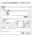
PC2の印刷制御手段32は、印刷設定条件の提案文書を受信すると(S21)、画面生成手段33により印刷設定画面を生成して表示する(S22)。ここで、PC2は、例えばプリンタ2の印刷能力を把握しており、プリンタ2の印刷能力に基づき印刷設定画面を構成するものとする。なお、S22の処理で印刷設定画面に提示される印刷設定条件の各項目のデフォルト値は、PC1で指定された印刷設定条件の値にすると良い。これにより、PC2のユーザが印刷設定画面を見たときにPC1のユーザがどのような設定で印刷するのか参考にしながら、印刷設定条件を指定することができる。
When receiving the print setting condition proposal document (S21), the
PC2の印刷制御手段32は、ユーザにより印刷設定画面を介して選択された印刷設定条件を受信し(S23)、例えばPC1がプリンタ2を印刷する能力がない場合には、自動的にプリンタ2をPC2と共有するように制御して(S24)、PC1がプリンタ2を使えるようにする。
The
すなわち、PC2の印刷制御手段32は、ユーザにより選択された印刷設定条件に基づいて印刷設定条件の回答文書を生成すると共に、例えばPC1がSMBを使用してプリンタ2へアクセスするためのアドレス等を印刷設定条件の回答文書に記載する。なお、PC2の印刷制御手段32より生成される印刷設定条件の回答文書については後述する。
That is, the
次に、PC2の印刷制御手段32は、PC1に印刷設定条件の回答文書を送信し(S25)、PC1の印刷制御手段12は、印刷設定条件の回答文書を受信する(S26)。
Next, the
上述したように、PC1の印刷制御手段12は、PC2から取得した回答文書に基づきプリンタ2に対する印刷設定条件を決定する。
As described above, the
<第1実施形態に係る印刷処理>
次に、図5を用いて、PC1の印刷制御手段12により実行される印刷処理について説明する。図5は、第1実施形態に係る印刷処理の流れを示すフローチャートである。図5に示す印刷処理では、図4に示す印刷設定条件決定処理においてPC1がPC2から取得した印刷設定条件に基づき印刷処理を実行する。
<Print Processing According to First Embodiment>
Next, print processing executed by the
まず、PC1の印刷制御手段12は、S10の処理で設定された自身の印刷設定に基づき、印刷データ生成手段13により印刷データを生成し(S30)、生成した印刷データをプリンタ1に送信する(S31)。プリンタ1は、通信手段20によりPC1から印刷データを受信すると(S32)、画像形成手段21により印刷処理を実行する(S33)。なお、例えば各拠点の通信デバイスには、通信デバイスに属するプリンタのIPアドレス等のネットワーク情報が予め設定されているものとする。
First, the
また、印刷制御手段12は、S26の処理で得られた印刷設定条件の回答文書に指定されたアドレス情報に基づき、SMBを用いてプリンタ2をPC2と共有する(S34)。また、印刷制御手段12は、共有状態のPC2のプリンタドライバにアクセスし、回答文書の印刷設定条件に基づき印刷データを生成する(S35)。
Further, the print control means 12 shares the printer 2 with the PC 2 using SMB based on the address information specified in the answer document for the print setting condition obtained in the process of S26 (S34). Further, the
次に、印刷制御手段12は、生成した印刷データを通信手段14によりプリンタ2に送信し(S36)、プリンタ2は、通信手段40により印刷データを受信すると(S37)、画像形成手段41により印刷処理を実行する(S38)。
Next, the
印刷制御手段12は、S38の処理で印刷処理が実行されると、PC2に印刷完了通知を送信し(S39)、PC2の印刷制御手段32は、PC1から印刷完了通知を受信すると(S40)、プリンタ2のプリンタドライバの共有を解除し(S41)、処理を終了する。これにより、PC2の印刷制御手段32は、プリンタ2での印刷終了後、プリンタ2が外部のユーザに不正に利用されるのを防ぐことを可能とする。
When the printing process is executed in the process of S38, the
<印刷方法決定処理で用いられる各文書について>
次に、図6を用いて、上述した印刷方法決定処理で用いられる各文書について説明する。図6は、第1実施形態に係る印刷方法決定処理においてPC1とPC2との間で交換される文書の一例を示している。図6(A)は、図3のS12の処理においてPC1の要求手段11からPC2へ送信される印刷方法の提案文書の一例を示し、図6(B)は、図3のS16の処理においてPC2の印刷制御手段32からPC1へ返信される印刷方法の回答文書の一例を示している。
<About each document used in the printing method determination process>
Next, each document used in the printing method determination process described above will be described with reference to FIG. FIG. 6 shows an example of a document exchanged between PC1 and PC2 in the printing method determination process according to the first embodiment. 6A shows an example of a printing method proposal document transmitted from the
図6(A)に示す提案文書には、印刷モードとして、"print"と"file−transfer"の2つが選択可能であることが示されている。また、デフォルトの設定として"print"が設定されている。 The proposed document shown in FIG. 6A shows that “print” and “file-transfer” can be selected as print modes. In addition, “print” is set as a default setting.
このように選択肢を文書に含めることにより、受信側のPC2において、この提案文書に基づいてユーザに対する問合わせ画面としての印刷方法選択画面を生成することが可能となる。なお、図6(A)に示すように、本実施形態では、印刷方法や印刷設定条件に関する提案文書や回答文書が、複数回交換されるため、同一の処理であることを示すための「id」が設定されている。 By including the options in the document in this way, the receiving PC 2 can generate a printing method selection screen as an inquiry screen for the user based on the proposed document. As shown in FIG. 6A, in this embodiment, since the proposal document and the answer document regarding the printing method and the print setting condition are exchanged a plurality of times, “id” for indicating the same processing is performed. "Is set.
図6(B)に示す回答文書には、PC2のユーザにより選択された印刷方法の回答が示されている。すなわち、図6(B)の例では、PC2のユーザにより"print"が選択されている。 In the answer document shown in FIG. 6B, the answer of the printing method selected by the user of the PC 2 is shown. That is, in the example of FIG. 6B, “print” is selected by the user of the PC 2.
<印刷設定条件決定処理に用いられる各文書について>
次に、図7を用いて、上述した印刷設定条件決定処理に用いられる各文書について説明する。図7は、第1実施形態に係る印刷設定条件決定処理においてPC1とPC2との間で交換される文書の一例を示している。図7(A)は、図4のS20の処理でPC1の要求手段11からPC2に送信される印刷設定条件の提案文書の一例を示し、図7(B)は、図4のS25の処理でPC2の印刷制御手段32からPC1に返信される印刷設定条件の回答文書の一例を示している。
<About each document used for print setting condition determination processing>
Next, each document used in the above-described print setting condition determination process will be described with reference to FIG. FIG. 7 shows an example of a document exchanged between PC1 and PC2 in the print setting condition determination processing according to the first embodiment. FIG. 7A shows an example of a print setting condition proposal document transmitted from the
図7(A)に示す提案文書では、PC1の使用するプリンタ情報、PC1のユーザにより指定された印刷設定条件が示されている。上述したように、PC1で指定された印刷設定条件を提案文書にて提示するのは、PC2において、PC1で指定された印刷設定条件を参考にして回答文書を作成可能するためである。
In the proposal document shown in FIG. 7A, printer information used by the
具体的には、図7(A)に示す提案文書は、大きく2つのパートを含み、例えばプリンタ情報を記述するための<printer>要素と、印刷設定条件を記述するための<settings>要素を含んでいる。例えば、<printer>要素には、PC1が、RPCSのversion2.66におけるフォーマットのPDL(Page Description Language)で生成することが示されている。
Specifically, the proposed document shown in FIG. 7A includes two parts, for example, a <printer> element for describing printer information and a <settings> element for describing print setting conditions. Contains. For example, the <printer> element indicates that the
PC2の印刷制御手段32は、上述した情報に基づいて、どのように印刷するか判断し、例えば、プリンタ2はPDLとしてPCLしか解釈できないため自身のプリンタドライバを公開してPC1とプリンタ2を共有して印刷させる等を決定し、図7(B)に示すような回答文書を生成する。
The
図7(B)に示す回答文書では、例えば<printer>要素(例えば図7(B)に示す(A))に、SMBを使用して自身(PC2の)のプリンタドライバにアクセスするように指定されている。なお、PC1が例えばPCLの生成能力を有し、図7(A)の提案文書において、例えば選択肢にPCLが提示されていた場合には、PC2の印刷制御手段32は、図7(B)に示す回答文書において、PC1の印刷制御手段12に対してPCLドライバを使用して印刷するように指定することが可能である。
In the answer document shown in FIG. 7B, for example, the <printer> element (for example, (A) shown in FIG. 7B) is specified to access its own printer driver (PC2) using SMB. Has been. If the
また、図7(A)に示す提案文書の<settings>要素に、アプリケーション共通の設定条件として、例えばページ範囲(all)と印刷部数(3)が設定され、プリンタごとの印刷設定条件として、用紙サイズ(A4)、割付(1ページ/ページ)、両面(オフ)、カラー/白黒(カラー)が設定されている。これらの設定情報は、PC1のユーザにより指定された印刷設定条件である。
Further, for example, a page range (all) and the number of copies (3) are set in the <settings> element of the proposal document shown in FIG. 7A as common setting conditions for the application. Size (A4), layout (1 page / page), duplex (off), and color / monochrome (color) are set. These setting information are print setting conditions designated by the user of the
PC2の印刷制御手段32は、この印刷設定条件及びプリンタ2の能力情報に基づいて、図4のS22の処理において画面生成手段33により印刷設定画面を生成する。この印刷設定画面により、例えばPC1において設定された情報を参考にしてPC2のユーザによりデフォルト値を変更させて、PC2のユーザによる印刷設定条件の入力の手間を軽減させることができる。同じ資料を印刷する場合には、大抵同様の設定になるためである。なお、PC2はプリンタ2の能力情報を予め知っているものとする。
The
また、PC2の印刷制御手段32は、印刷設定画面を介してユーザから入力された印刷設定条件に基づいて、図7(B)に示す回答文書を生成する。図7(B)に示す回答文書には、<settings>要素において、印刷部数(5)、カラー/白黒(白黒)に設定が変更され、例えば両面の項目は削除されている。 Further, the print control means 32 of the PC 2 generates an answer document shown in FIG. 7B based on the print setting conditions input from the user via the print setting screen. In the answer document shown in FIG. 7B, the setting is changed to the number of copies (5) and color / monochrome (black and white) in the <settings> element, and for example, the items on both sides are deleted.
ここで、印刷部数、カラー/白黒の項目は、PC2のユーザにより変更された情報が示されている。なお、両面の項目は、PC2の画面生成手段33による印刷設定画面の生成段階で、PC2の印刷制御手段32により削除されたものである。これはプリンタ2が両面印刷機能を有していないためである。
Here, the number of copies to be printed and the color / monochrome items indicate information changed by the user of the PC 2. The double-sided items are deleted by the
上述したように、例えば図7(A)に示す提案文書では、プリンタ情報と印刷設定条件の2つの要素についてを提案しているが、プリンタ情報の交換手続と印刷設定条件の交換手続とを分割して行うことも可能である。 As described above, for example, the proposal document shown in FIG. 7A proposes two elements of printer information and print setting conditions, but the printer information exchange procedure and the print setting condition exchange procedure are divided. It is also possible to do this.
すなわち、例えばPC1がPCLドライバを持っている場合には、プリンタ情報の交換手続後、PCLを用いて印刷するのが決定した段階で、PC1の要求手段11がPCLドライバの能力情報に基づいて印刷設定条件の提案文書を生成し、PC2の印刷制御手段32がこの印刷設定条件の提案文書のみから上述した印刷設定画面を生成させても良い。
That is, for example, when the
また、図7(B)に示す回答文書において、<printer>要素以下は、PC2の印刷制御手段32により設定され、<setting>要素以下は、PC2のユーザにより設定された情報が示されている。このように設定者が異なる場合に、図7に示す提案・回答を2回に分けて行っても良いし、実装上の都合により複数回に分けて行っても良い。 In the response document shown in FIG. 7B, the <printer> element and below are set by the print control means 32 of the PC 2, and the <setting> element and below are information set by the user of the PC 2. . In this way, when the setters are different, the proposal / reply shown in FIG. 7 may be divided into two times, or may be divided into a plurality of times for convenience of implementation.
<第2実施形態>
<印刷制御システムの全体構成>
次に、図8を用いて、第2実施形態に係る印刷制御システムの全体構成について説明する。図8は、第2実施形態に係る印刷制御システムの全体構成を示している。第2実施形態の印刷制御システム101は、第1実施形態の印刷制御システム100と比較して、拠点3が新たに設置され、拠点3のPC3が遠隔会議に参加している点と、遠隔会議のセッションを開始するために呼制御サーバが備えられている点と、プリンタ1とプリンタ2をサポートするPDLが同一(RPCS)である点が異なる。また、拠点3にはプリンタは存在しない。
Second Embodiment
<Overall configuration of print control system>
Next, the overall configuration of the print control system according to the second embodiment will be described with reference to FIG. FIG. 8 shows the overall configuration of the print control system according to the second embodiment. The
呼制御サーバは、ネットワークに接続され、例えば第1の端末装置から第2の端末装置又は第2の端末装置に属する出力装置に所定のデータを出力する際に、出力方法及び設定情報を取得するための通信セッションを確立する。 The call control server is connected to the network, and acquires an output method and setting information when outputting predetermined data from, for example, the first terminal device to the second terminal device or the output device belonging to the second terminal device. Establish a communication session for
図8の例では、拠点1におけるPC1のアプリケーション実行手段10は、遠隔会議アプリケーションを実行する際に呼制御サーバを通して遠隔会議セッションを開始し、PC1の印刷制御手段12は、呼制御サーバを通してプリントセッションを開始する。このように、呼制御サーバでセッションを制御することにより、セッション内のメディア制御やセッションのライフサイクル管理が容易となる。
In the example of FIG. 8, the
<印刷制御システムの機能構成>
次に、図9を用いて、上述した印刷制御システム101の機能構成について説明する。図9は、第2実施形態に係る印刷制御システムの機能構成を示している。図8に示したように、第1実施形態の印刷制御システム100と比較して、第2実施形態の印刷制御システム101は、呼制御サーバ50とPC3が設けられている点が異なる。なお、同一の構成については同一の符号を付して、ここでの説明は省略する。
<Functional configuration of print control system>
Next, the functional configuration of the above-described
呼制御サーバ50は、通信手段51と、呼制御手段52と、記録手段(DB)53とを有するように構成される。呼制御サーバ50は、通信手段51を通してネットワークに接続され、PC1〜PC3と通信を行う。
The
呼制御手段52は、例えばSIP(Session Initiation Protocol)やXMPP(eXtensible Messaging and Presence Protocol)等を利用して、各セッションの開始・終了・更新時に、各PC1〜PC3の呼を受信すると、呼の転送設定に基づき転送するよう制御する。 When the call control means 52 receives a call from each PC1 to PC3 at the start / end / update of each session, for example, using SIP (Session Initiation Protocol) or XMPP (Extensible Messaging and Presentation Protocol), etc. Control transfer based on transfer settings.
記録手段53は、呼制御手段52が各PCに呼を転送させるための転送設定情報等の各種データファイルをDBに格納する。
The
PC2は、通信手段30と、印刷データ生成手段31と、印刷制御手段32と、画面生成手段33と、アプリケーション実行手段34と、映像出力手段36と、映像入力手段37と、画面表示手段38とを有するように構成される。なお、第2実施形態におけるPC2は、例えばデスクトップPC等であり、大別すると本体とディスプレイを有する。
The PC 2 includes a
すなわち、第2実施形態のPC2は、第1実施形態のPC2をノートPCからデスクトップPCとし、映像表示手段35の代わりに、映像を出力する映像出力手段36と、映像を入力する映像入力手段37と、例えば外付けのディスプレイ等である画面表示手段38の構成が追加されている。 That is, the PC 2 of the second embodiment changes the PC 2 of the first embodiment from a notebook PC to a desktop PC, and instead of the video display means 35, a video output means 36 for outputting video and a video input means 37 for inputting video. For example, the configuration of the screen display means 38 which is an external display or the like is added.
PC3は、例えばノートPCであり、通信手段60と、印刷制御手段61と、アプリケーション実行手段62と、映像表示手段63とを有するように構成される。なお、PC3は、例えば第1実施形態のPC2と同様の構成としても良い。
The
<プリントセッションの開始>
次に、図10及び図11を用いて、上述したプリントセッションの開始について説明する。図10は、第2実施形態に係るプリントセッション開始要求の流れを示すフローチャートである。また、図11は、第2実施形態に係るプリントセッション開始要求の確認応答の流れを示すフローチャートである。なお、図10のS50、S51の処理は、図3のS10、S11の処理と同様の処理であるため、ここでの説明を省略する。
<Start print session>
Next, the start of the above-described print session will be described with reference to FIGS. 10 and 11. FIG. 10 is a flowchart showing the flow of a print session start request according to the second embodiment. FIG. 11 is a flowchart showing the flow of a confirmation response to a print session start request according to the second embodiment. Note that the processing in S50 and S51 in FIG. 10 is the same as the processing in S10 and S11 in FIG.
図10に示すように、PC1の印刷制御手段12は、S51の処理で会議参加者のネットワーク情報を取得すると、プリントセッションを開始する。第2実施形態では、PC1〜PC3において遠隔会議が行われているため、プリントセッションは、例えばPC1とPC2、PC1とPC3の2つのセッションが生成される。
As illustrated in FIG. 10, the
PC1の印刷制御手段12は、プリントセッション開始要求を呼制御サーバ50に送信すると(S52)、呼制御サーバ50は、通信手段51によりプリントセッション開始要求を受信し(S53)、呼制御手段52により記録手段53を参照して転送を制御して、プリントセッション開始要求をPC2に送信する(S54)。
When the
次に、PC2の印刷制御手段32は、通信手段30により呼制御サーバ50からプリントセッション開始要求を受信すると(S55)、ユーザに対して印刷の問い合わせを行う(S56)。ここで、PC2は、画面生成手段33によりPC1において印刷が行われることをPC2のユーザに通知する画面(例えば後述する図22に示すダイアログ)を生成して、PC2のユーザに対しても印刷するか問い合わせを行う。PC2は、ユーザによる印刷指示を受けると(S57)、(A)へ進む。
Next, when the print control means 32 of the PC 2 receives a print session start request from the
なお、PC1からのプリントセッション開始要求の具体例については後述する。また、PC1の印刷制御手段12は、PC3にも同様にプリントセッション開始要求を送信する(S58〜S63)。
A specific example of a print session start request from the
また、図11に示すように、(A)の処理から引き続き、PC2の印刷制御手段32は、S57の処理で受けたユーザの指示に基づき、プリントセッション開始要求の応答を呼制御サーバ50に送信する(S70)。
Further, as shown in FIG. 11, the
ここで、PC2の印刷制御手段32は、図10のS57の処理においてPC2のユーザから印刷指示を受けた場合、S70の処理でプリントセッション開始要求の応答に「成功応答」を含める。また、PC2のユーザから印刷しない指示を受けた場合、S70の処理でプリント開始要求の応答に「エラー応答」を含める。
Here, when the
呼制御サーバ50は、通信手段51によりプリントセッション開始要求の応答をPC2から受信すると(S71)、呼制御手段52により転送を制御し、プリントセッション開始要求の応答をPC1に送信する(S72)。
When the
次に、PC1の印刷制御手段12が、呼制御サーバ50からプリントセッション開始要求の応答を受信すると(S73)、プリントセッション開始要求の確認応答を呼制御サーバ50に送信し(S74)、通信手段51によりプリントセッション開始要求の確認応答を受信する(S75)。
Next, when the print control means 12 of the
次に、呼制御手段52により転送を制御し、プリントセッション開始要求の確認応答をPC2に送信すると(S76)、PC2の通信手段30により呼制御サーバ50からのプリントセッション開始要求の確認応答を受信する(S77)。また、PC3はPC2と同様の処理を実行する(S78〜S85)。
Next, when the transfer is controlled by the call control means 52 and the confirmation response of the print session start request is transmitted to the PC 2 (S76), the confirmation response of the print session start request from the
上述したように、PC1の印刷制御手段12は、PC2及びPC3からプリントセッション開始要求の応答を受信した後、PC2及びP3に対してプリントセッション開始要求の応答確認を送信する。これは、PC1のユーザが、PC2及びPC3においてプリントセッション開始要求を受信してからプリントセッション開始要求の応答を送信するまでの間(ユーザ回答待ち状態の間)にセッション開始をキャンセルする可能性があるためである。
As described above, after receiving the print session start request response from the PC 2 and
なお、S77及びS85の処理においてPC2及びPC3がプリントセッション開始要求の応答確認を受信し、PC2及びPC3のそれぞれの上述したS70及びS78の処理の応答が「成功応答」の場合にはプリントセッションが開始され、「エラー応答」の場合には、そのまま処理を終了する。なお、ここでは、PC2及びPC3とも「成功応答」だったものとする。
In the processes of S77 and S85, the PC 2 and
<第2実施形態に係る印刷方法決定処理>
次に、図12を用いて、プリントセッション開始後の印刷方法決定処理について説明する。図12は、第2実施形態に係る印刷方法決定処理の流れを示すフローチャートである。なお、第2実施形態に係る印刷方法決定処理の流れは、第1実施形態に係る印刷方法決定処理の流れと同様の処理が行われる。
<Print Method Determination Process According to Second Embodiment>
Next, a printing method determination process after starting a print session will be described with reference to FIG. FIG. 12 is a flowchart illustrating a flow of a printing method determination process according to the second embodiment. Note that the flow of the printing method determination process according to the second embodiment is the same as the flow of the printing method determination process according to the first embodiment.
例えば、図12に示すPC1が要求手段11によりPC2に対して印刷方法の提案を行い、PC1がPC2の印刷制御手段32から印刷方法の回答を受信するS90〜S95の処理の流れは、図3に示すS12〜S17の処理の流れと同様であるため、ここでの説明を省略する。また、図12に示すPC1が要求手段11によりPC3に対して印刷方法の提案を行い、PC1がPC3の印刷制御手段61から印刷方法の回答を受信するS96〜S101の処理の流れも、図3に示すS12〜S17の処理の流れと同様であるため、ここでの説明を省略する。
For example, the flow of processing from S90 to S95 in which the
なお、PC1の要求手段11からPC2又はPC3に送信される印刷方法の提案文書は、上述した図6(A)と同様の内容となる。なお、図12のS92、S98の処理で表示される印刷方法選択画面は、PC2及びPC3により図6(A)に示す印刷方法の提案文書に基づき生成され、後述する図22に示すようなダイアログとして表示される。
Note that the print method proposal document transmitted from the
また、PC2、PC3の各ユーザにより印刷方法選択画面を介して選択された内容が、PC2の印刷制御手段32、PC3の印刷制御手段61により図6(B)に示す印刷方法の回答文書として生成され、図12のS94又はS100の処理において、PC2又はPC3からPC1に送信される。 Further, the contents selected via the printing method selection screen by the users of PC2 and PC3 are generated as answer documents for the printing method shown in FIG. 6B by the printing control means 32 of PC2 and the printing control means 61 of PC3. In step S94 or S100 in FIG. 12, the data is transmitted from PC2 or PC3 to PC1.
上述したように、第2実施形態では、プリントセッション開始後、PC1は、セッション情報にしたがってPC2及びPC3と通信し、PC2及びPC3から受信した印刷方法の回答文書に基づき印刷方法を決定して、後述する印刷設定条件を決定する。
As described above, in the second embodiment, after the start of the print session, the
<第2実施形態に係る印刷設定条件決定処理>
次に、図13を用いて、図12に示す印刷方法決定後の印刷設定条件決定処理について説明する。図13は、第2実施形態に係る印刷設定条件決定処理の流れを示すフローチャートである。なお、第2実施形態に係る印刷設定条件決定処理の流れは、第1実施形態に係る印刷方法決定処理の流れと同様の処理が行われる。
<Print Setting Condition Determination Process According to Second Embodiment>
Next, the print setting condition determination process after the print method determination shown in FIG. 12 will be described with reference to FIG. FIG. 13 is a flowchart showing a flow of print setting condition determination processing according to the second embodiment. The flow of the print setting condition determination process according to the second embodiment is the same as the flow of the print method determination process according to the first embodiment.
例えば、図13に示すPC1が要求手段11によりPC2に対して印刷設定条件の提案を行い、PC1がPC2の印刷制御手段32から印刷設定条件の回答を受信するS110〜S115の処理の流れは、図4に示すS20〜S23、S25〜S26の処理の流れと同様であるため、ここでの説明を省略する。また、図13に示すPC1が要求手段11によりPC3に対して印刷設定条件の提案を行い、PC1がPC3の印刷制御手段61から印刷設定条件の回答を受信するS116〜S121の処理の流れは、図4に示すS20〜S23、S25〜S26の処理の流れと同様であるため、ここでの説明を省略する。
For example, the process flow of S110 to S115 in which the
なお、PC1の要求手段11からPC2に対する印刷設定条件の提案文書とPC2の印刷制御手段32により生成されるPC1に対する印刷設定条件の回答文書の一例については後述する。また、PC1の要求手段11からPC3に対する印刷設定条件の提案文書とPC3の印刷制御手段61により生成されるPC1に対する印刷設定条件の回答文書の一例については後述する。
An example of the print setting condition proposal document for the PC 2 from the
<第2実施形態に係る印刷処理>
次に、図14を用いて、上述した印刷制御システム101により実行される印刷処理について説明する。図14は、第2実施形態に係る印刷処理の流れを示すフローチャートである。図14に示す印刷処理では、図13に示す印刷設定条件決定処理においてPC1がPC2及びPC3から取得した印刷設定条件に基づき、印刷処理を実行する。
<Printing Process According to Second Embodiment>
Next, print processing executed by the above-described
なお、図14のS130〜S133の処理は、図5のS30〜S33の処理と同様であるため、ここでの説明は省略する。なお、図14に示すS130〜S133の処理では、PC1は、自身の印刷設定に基づき印刷データを生成し、プリンタ1に送信して印刷する。
Note that the processing of S130 to S133 in FIG. 14 is the same as the processing of S30 to S33 in FIG. In the processing of S130 to S133 shown in FIG. 14, the
次に、PC1の印刷制御手段12は、印刷データ生成手段13によりプリンタ2に出力するために印刷データを生成する(S134)。第2実施形態では、PC1はプリンタ2をサポートするPDLを生成可能であるため、上述した図13のS115の処理にて、PC2から受信した印刷設定条件の回答文書に基づき印刷データを生成する。
Next, the
次に、PC1の印刷制御手段12は、S134の処理で生成した印刷データを通信手段14によりプリンタ2に送信し(S135)、プリンタ2は通信手段40により印刷データを受信すると(S136)、画像形成手段41により印刷処理を行う(S137)。
Next, the
次に、PC1の印刷制御手段12は、PC3から受信した印刷方法の回答文書に基づき、PC3にファイルを転送するため、記録手段15のファイルシステムからファイルを取得する(S138)。次に、PC1の印刷制御手段12は、図13のS121の処理にてPC3から受信した印刷設定条件の回答文書に基づき、PC3に通信手段14によりファイルを送信する(S139)。
Next, the
PC3は、通信手段60によりPC1からファイルを受信すると(S140)、アプリケーション実行手段62によりユーザから指示されたアプリケーションを実行してファイルを開き、映像表示手段63にファイルを表示する(S141)。
When the
<プリントセッションの終了>
次に、図15を用いて、上述したプリントセッションの終了について説明する。図15は、第2実施形態に係るプリントセッション終了要求の流れを示すフローチャートである。図14に示す印刷処理が完了すると、PC1は、プリントセッションを終了する。
<End print session>
Next, the end of the above-described print session will be described with reference to FIG. FIG. 15 is a flowchart showing a flow of a print session end request according to the second embodiment. When the printing process shown in FIG. 14 is completed, the
図15に示すように、PC1の印刷制御手段12は、プリントセッション終了要求を呼制御サーバ50に送信すると(S150)、呼制御サーバ50は、通信手段51によりプリントセッション終了要求を受信し(S151)呼制御手段52により転送を制御し、プリントセッション終了要求をPC2に送信する(S152)。
As shown in FIG. 15, when the print control means 12 of the
PC2の印刷制御手段32は、通信手段30により呼制御サーバ50からプリントセッション終了要求を受信すると(S153)、プリントセッション終了要求の応答を呼制御サーバ50に送信し(S154)、呼制御サーバ50は、通信手段51によりPC2からプリントセッション終了要求の応答を受信すると(S155)、PC2からのプリントセッション終了要求の応答をPC1に送信する(S156)。PC1の印刷制御手段12は、呼制御サーバ50からプリントセッション終了要求の応答を受信すると(S157)、処理を終了する。
When the
なお、PC1の印刷制御手段12から送信されるプリントセッション終了要求の具体例については後述する。また、PC1の印刷制御手段12は、PC3にも同様にプリントセッション終了要求を送信する(S158〜S165)。
A specific example of the print session end request transmitted from the
上述したように、PC1の印刷制御手段12は、プリントセッション終了要求を、呼制御サーバ50を経由してPC2及びPC3に送信し、PC2及びPC3がプリントセッション終了要求を受信する(上述したS153、S161の処理)と、PC2の印刷制御手段32及びPC3の印刷制御手段61はプリントセッションで使用したリソースを開放する。リソースの開放としては、例えば接続ポートの開放等を行う。なお、第1実施形態のようにプリンタドライバを共有した場合には、プリントセッション終了要求の受信後に設定を解除する。
As described above, the
また、PC1の印刷制御手段12は、PC2及びPC3からプリントセッション終了要求の応答を受信すると、同様にプリントセッションで使用したリソースを開放し、処理を終了する。
Further, when receiving the print session end request response from the PC 2 and
<プリントセッション開始要求等に用いられる文書について>
次に、図16を用いて、上述したプリントセッションで用いられる各文書について説明する。図16は、第2実施形態のプリントセッションで用いられる各文書の具体例を示している。
<Documents used for print session start requests, etc.>
Next, each document used in the above-described print session will be described with reference to FIG. FIG. 16 shows a specific example of each document used in the print session of the second embodiment.
図16(A)は、例えば図10のS52等の処理においてPC1の印刷制御手段12から呼制御サーバ50を介してPC2へ送信されるプリントセッション開始要求文書の一例を示している。図16(A)に示す文書は、呼制御サーバ50を介して送信されるため、ヘッダーにはURIが指定され、セッションを特定するためのCall−ID等が記載されている。
FIG. 16A shows an example of a print session start request document transmitted from the
また、文書本体には、PC1のプリントセッション情報が記載されている。すなわち、プリントセッションであることを示す(session=print)他、この後の印刷方法の提案・回答、印刷設定条件の提案・回答の通信で使用されるPC1のIPアドレス(192.168.11.11)とポート番号(10000)等が指定されている。
Further, the print session information of the
図16(B)は、PC2の印刷制御手段32から呼制御サーバ50を介してPC1に返信されるプリントセッション開始要求の応答文書の一例を示している。図16(B)に示すように、文書一行目の応答の可否(図16(B)の例ではOK)は、上述した図10のS56の問い合わせに対するS57のユーザからの印刷指示等の応答結果が示されている。
FIG. 16B shows an example of a response document for a print session start request returned from the print control means 32 of the PC 2 to the
また、文書本体には、PC2のプリントセッション情報として、この後の印刷方法の提案・回答、印刷設定条件の提案・回答の通信で使用されるPC2のIPアドレス(192.168.21.11)とポート番号(10000)が指定されている。 In the document body, as the print session information of the PC 2, the IP address of the PC 2 (192.168.21.11) used in the subsequent communication of the print method proposal / reply and the print setting condition proposal / reply And the port number (10000) are designated.
図16(C)は、PC1の印刷制御手段12から呼制御サーバ50を介してPC2へ送信されるプリントセッション開始要求の確認応答文書の一例を示している。図16(C)に示すように、プリントセッション情報の交換が終了しているため文書本体には特に記載されていない。
FIG. 16C shows an example of a print session start request confirmation response document transmitted from the print control means 12 of the
図16(D)は、PC1の印刷制御手段12から呼制御サーバ50を介してPC2へ送信されるプリントセッション終了要求の文書の一例を示している。図16(D)に示すように、文書本体には特に記載されていない。
FIG. 16D shows an example of a print session end request document transmitted from the print control means 12 of the
<印刷設定条件決定処理で用いられる各文書>
次に、図17及び図18を用いて、上述した図13の印刷設定条件決定処理で用いられる各文書について説明する。図17は、第2実施形態に係る印刷設定条件決定処理においてPC1とPC2との間で交換される文書の一例を示している。また、図18は、第2実施形態に係る印刷設定条件決定処理においてPC1とPC3との間で交換される文書の一例を示している。
<Each document used in print setting condition determination processing>
Next, with reference to FIGS. 17 and 18, each document used in the above-described print setting condition determination process in FIG. 13 will be described. FIG. 17 shows an example of a document exchanged between PC1 and PC2 in the print setting condition determination processing according to the second embodiment. FIG. 18 shows an example of a document exchanged between PC1 and PC3 in the print setting condition determination process according to the second embodiment.
具体的には、図17(A)は、図13のS110の処理でPC1の要求手段11からPC2へ送信される印刷設定条件の提案文書の一例を示し、図17(B)は、図13のS114の処理でPC2の印刷制御手段32からPC1へ返信される印刷設定条件の回答文書の一例を示している。
Specifically, FIG. 17A shows an example of a print setting condition proposal document transmitted from the
図17(A)に示す提案文書は、図7(A)に示す提案文書と同一の例であり、例えばPC1のプリンタ情報とPC1で指定された印刷設定条件が示されている。 The proposed document shown in FIG. 17A is the same example as the proposed document shown in FIG. 7A, and shows, for example, the printer information of PC1 and the print setting conditions specified by PC1.
図17(B)に示す回答文書では、例えば回答文書の(B)に示す<formar>要素が、図17(A)に示す提案文書と変更がなく、PC1で印刷データを生成することが指定されている。また、<dest>要素内に、印刷データ生成後にPC1が送信する送信先(図17(B)の例では(192.168.21.21)、すなわち、プリンタ2)が指定されている。
In the answer document shown in FIG. 17B, for example, the <former> element shown in (B) of the answer document is not changed from the proposed document shown in FIG. Has been. In the <dest> element, a transmission destination ((192.168.21.21 in the example of FIG. 17B), that is, the printer 2) to which the
PC2の印刷制御手段32は、上述した図13のS111の処理で、図17(A)に示す提案文書を受信すると、文書の<printer>要素の情報に基づき、詳細な印刷設定条件を決定する。ここで、PC2は、プリンタ2がプリンタ1と同様にRPCSをサポートしているため、PC1からプリンタ2用の印刷データを生成できると判断する。
When the
そこで、PC2の印刷制御手段32は、図17(B)に示す回答文書において、例えばPC1が印刷データを生成し、直接プリンタ2に出力するよう指示する。図17(B)の回答文書の<printer>要素には、例えばプリンタ2のIPアドレス、ポート番号、プロトコルが指定されている。
Accordingly, the print control means 32 of the PC 2 instructs the
また、図17(B)に示す回答文書の<setting>要素は、図17(A)に示す提案文書と比較すると、印刷部数、両面、カラー/白黒の項目が異なっている。すなわち、図13のS112の処理では、PC2の画面生成手段33により図17(A)に示す提案文書に基づいて印刷設定画面が生成され、後述する図23に示すような印刷設定ダイアログがPC2のユーザに提示される。上述した項目は、ユーザにより印刷設定画面で印刷設定条件を変更された内容が示されている。 Also, the <setting> element of the answer document shown in FIG. 17B differs from the proposal document shown in FIG. 17A in the number of copies, double-sided, and color / monochrome. That is, in the process of S112 in FIG. 13, a print setting screen is generated based on the proposal document shown in FIG. 17A by the screen generation means 33 of the PC 2, and a print setting dialog as shown in FIG. Presented to the user. The items described above indicate the contents of changing the print setting conditions on the print setting screen by the user.
このように、PC2の印刷制御手段32は、プリンタ情報に基づいて判断された印刷出力方法や、ユーザにより印刷設定画面で変更された印刷設定条件に基づき、図17(B)に示す印刷設定条件回答文書を生成して、PC1に返信する。
As described above, the
また、図18(A)は、図13のS116の処理でPC1の印刷制御手段12からPC3へ送信される印刷設定条件の提案文書の一例を示し、図18(B)は、図13のS120の処理でPC3の印刷制御手段61からPC1へ返信される印刷設定条件の回答文書の一例を示している。
FIG. 18A shows an example of a print setting condition proposal document transmitted from the print control means 12 of the
なお、第2実施形態において、PC3は、図8に示すようにプリンタを有していないため、図12のS99の処理でPC3の印刷制御手段61からPC1へ回答された印刷方法の回答文書ではファイル転送モードが指定されたものとする。
In the second embodiment, since the
図18(A)に示す提案文書では、上述した図12の印刷方法決定処理に基づき、PC1からPC3に送信するファイル名、フォーマット、送信プロトコル等が示されている。
In the proposed document shown in FIG. 18A, the file name, format, transmission protocol, and the like transmitted from the
また、図18(B)に示す回答文書は、図18(A)に示す提案文書と比較して、<file>要素に変更はなく、例えば<dest>要素において、ファイルの送信先(PC3のIPアドレスとポート番号)、送信プロトコル、ファイルのフォーマットが指定されている。 18B does not change the <file> element as compared to the proposal document shown in FIG. 18A. For example, in the <dest> element, the file destination (PC3 IP address and port number), transmission protocol, and file format are specified.
すなわち、上述した図13のS118の処理では、例えばPC3により図18(A)に示す提案文書に基づいてファイル転送設定画面が生成され、後述する図24に示すようなダイアログがPC3のユーザに提示される。PC3の印刷制御手段61は、ユーザによりファイル転送設定画面で指定された設定条件に基づき、図18(B)に示す回答文書を生成しPC1へ返信する。PC1の印刷制御手段12は、図18(B)に示す回答文書の<file>要素におけるフォーマット指定、ファイル名の拡張子等が変更されていた場合には、ファイルをフォーマット変換した上でPC3に送信する。
That is, in the process of S118 of FIG. 13 described above, for example, the
<印刷ダイアログの例>
次に、図19及び図20を用いて、第2実施形態に係る印刷処理においてPC1で表示される各種設定画面について説明する。図19は、PC1で表示される印刷画面を説明するための図である。また、図20は、PC1で表示される印刷設定画面を説明するための図である。
<Example of print dialog>
Next, various setting screens displayed on the
図19及び図20に示す画面は、上述した図10のS50等の処理において、例えばPC1のユーザから共有印刷を行うための印刷指示及び印刷設定条件等を受けるために表示される画面である。
The screens shown in FIGS. 19 and 20 are screens that are displayed in order to receive, for example, a print instruction and print setting conditions for performing shared printing from the user of the
具体的には、図19に示す印刷画面は、ユーザが共有印刷を実行する場合に通常の印刷と同様に印刷ダイアログを開くと表示される。ここで、ユーザが、例えばプリンタドライバ(図19の例では、「会議プリンタ」のアイコン)を選択し、印刷ボタンを押すと、本実施形態に係る印刷制御機能が実行される。なお、図19に示す「ページ範囲」、「部数」等は、通常のアプリケーションによる印刷設定項目である。 Specifically, the print screen shown in FIG. 19 is displayed when the user opens the print dialog in the same way as normal printing when executing shared printing. Here, when the user selects, for example, a printer driver (“conference printer” icon in the example of FIG. 19) and presses the print button, the print control function according to the present embodiment is executed. Note that “page range”, “number of copies”, and the like shown in FIG. 19 are print setting items by a normal application.
また、図20に示す印刷設定画面は、図19に示す印刷ボタンが押されると表示され、実際に用いるプリンタを選択するための画面が示される。すなわち、図19に示す仮想プリンタ(会議プリンタ)ではなく、例えば事前に設定された拠点1のプリンタ1が表示される。
The print setting screen shown in FIG. 20 is displayed when the print button shown in FIG. 19 is pressed, and a screen for selecting a printer to be actually used is shown. That is, instead of the virtual printer (conference printer) shown in FIG. 19, for example, the
また、図20に示す印刷設定画面は、通常のアプリケーションによる印刷設定項目と、プリンタ固有の印刷設定項目を入力する画面が表示されている。ここで、通常のアプリケーションによる印刷設定項目は、図19に示す画面で指定された内容が表示され、プリンタ固有の印刷設定項目は、例えば原稿サイズ、集約、画面、カラー/白黒の設定項目が示されるため、ユーザにより各設定項目について指定ができる。 The print setting screen shown in FIG. 20 displays a screen for inputting print setting items by a normal application and print setting items unique to the printer. Here, the contents specified on the screen shown in FIG. 19 are displayed as the print setting items by the normal application, and the print setting items unique to the printer include, for example, the original size, aggregation, screen, and color / monochrome setting items. Therefore, the user can specify each setting item.
<PC2及びPC3で表示される画面>
次に、図21〜図24を用いて、上述した印刷処理においてPC2及びPC3で表示される表示画面について説明する。図21は、PC2及びPC3で表示される印刷許可画面を説明するための図であり、図22は、PC2又はPC3で表示される印刷方法選択画面を説明するための図である。また、図23は、PC2で表示される印刷設定画面を説明するための図であり、図24は、PC3で表示されるファイル転送設定画面を説明するための図である。
<Screen displayed on PC2 and PC3>
Next, display screens displayed on the PC 2 and
図21に示すPC2及びPC3で表示される印刷許可画面は、上述した図10のS56又はS62の処理においてPC2、PC3がPC1からのプリントセッション開始要求を受信した場合に、PC2、PC3のユーザに印刷の問い合わせを行うために表示される。例えば、図21の例では、「PC1がファイルを印刷しようとしています。こちらも印刷しますか?」とユーザに問い合わるダイアログが表示されている。 The print permission screen displayed on PC2 and PC3 shown in FIG. 21 is displayed to the user of PC2 or PC3 when PC2 or PC3 receives a print session start request from PC1 in the process of S56 or S62 of FIG. Displayed to make a print inquiry. For example, in the example of FIG. 21, a dialog is displayed asking the user “PC1 is about to print a file. Do you want to print this too?”.
ここで、ユーザにより図21に示す「OK」ボタンが押された場合には、上述した図16(B)に示すプリントセッション開始要求の応答文書に「OK」が記載され、PC1へ返信される(成功応答)。また、ユーザにより図21に示す「キャンセル」ボタンが押された場合には、上述した図16(B)に示すプリントセッション開始要求の応答文書の一行目に「Not Acceptable Here」等のエラー原因が記載されてPC1へ返信される(エラー応答)。なお、上述のように記載されたプリントセッション開始要求の応答文書は、図11のS70又はS78の処理で呼制御サーバ50を介してPC1に返信される。
If the user presses the “OK” button shown in FIG. 21, “OK” is described in the response document for the print session start request shown in FIG. 16B and is returned to the
また、図22に示す印刷方法選択画面は、上述した図12のS91又はS97の処理において、プリントセッション開始後にPC2又はPC3がPC1から印刷方法の提案文書を受信した際に、印刷方法をユーザに選択させるために表示される。例えば、図22の例では、「ファイルの出力手段を選択してください」と問合わせるダイアログが示され、「印刷」、「表示」、「キャンセル」の各ボタンが選択できるようになっている。
In addition, the printing method selection screen shown in FIG. 22 displays the printing method to the user when the PC 2 or
なお、図22に示すPC2又はPC3で表示される印刷方法選択画面は、上述した図6(A)に示すPC1からの印刷方法の提案文書に基づいて生成される。
Note that the printing method selection screen displayed on the PC 2 or
ここで、ユーザにより図22に示す「印刷」ボタンが押された場合には、PC2の印刷制御手段32又はPC3の印刷制御手段61により図6(B)に示す印刷方法の回答文書(print)が生成され、生成された回答文書は、上述した図12のS94又はS100の処理でPC1へ返信される。
Here, when the user presses the “print” button shown in FIG. 22, an answer document (print) of the printing method shown in FIG. 6B by the print control means 32 of the PC 2 or the print control means 61 of the
また、ユーザにより図22に示す「表示」ボタンが押された場合には、PC2の印刷制御手段32又はPC3の印刷制御手段61により図6(B)に示す印刷方法の回答文書に「file−transfer」が設定された回答文書が生成される。また、「キャンセル」ボタンが押された場合には、値は設定されず、PC1は、印刷方法の回答文書を受信した後、上述した図15に示すプリントセッション終了要求によりプリントセッションを終了する。
When the user presses the “display” button shown in FIG. 22, the print control means 32 of the PC 2 or the print control means 61 of the
また、図23に示すPC2で表示される印刷設定画面は、上述した図13のS112等の処理において、PC1から印刷設定条件の提案文書を受信した際に、PC2のユーザに提示される印刷設定ダイアログである。
Also, the print setting screen displayed on the PC 2 shown in FIG. 23 is the print setting presented to the user of the PC 2 when the print setting condition proposal document is received from the
すなわち、PC2の印刷制御手段32は、上述した図17(A)に示す印刷設定の提案文書の<settings>要素において指定される印刷設定情報と、プリンタ2の能力情報とに基づき、画面生成手段33により図23等に示す印刷設ダイアログを生成する。なお、PC2の印刷制御手段32は、例えばプリンタ2の能力情報のみから画面生成手段33により印刷設定ダイアログを生成することが可能であるが、印刷設定ダイアログには、PC1において指定された印刷設定条件(情報)に基づいてデフォルト値を設定しておく。これにより、PC2のユーザは、PC1において指定された印刷設定条件を参考にしながら各項目の値を変更することが可能となる。
That is, the
例えば、PC2のユーザが図23に示す印刷設定ダイアログ内で、「部数」、「両面」、「カラー/白黒」の設定を変更し、「印刷」ボタンを押すと、PC2の印刷制御手段32は、上述した図17(B)に示す印刷設定条件の回答文書を生成して、図13のS114の処理でPC1に返信する。
For example, when the user of the PC 2 changes the setting of “number of copies”, “double-sided”, “color / black and white” in the print setting dialog shown in FIG. 23 and presses the “print” button, the
また、図24に示すPC3に表示されるファイル転送設定画面は、上述した図13のS118等の処理において、PC1からの印刷設定条件の提案文書を受信した際に、PC3のユーザに提示されるダイアログである。
Further, the file transfer setting screen displayed on the
すなわち、PC3の印刷制御手段61は、上述した図18(A)に示す印刷設定条件の提案文書のPC1から転送されるファイル名(meeting.doc)、フォーマット「×××」等に基づき、図24に示すファイル転送設定画面を生成する。PC3に対する印刷方法は、図12に示すS98の処理において、PC3の拠点3にはプリンタがないため、図22の印刷方法選択画面の「表示(ファイル転送)」の選択により決定されていたものとする。また、上述した図18(A)に示す印刷設定条件の提案文書では、PC3への通信プロトコル、ファイルの名前、フォーマット等が提案されていたものとする。
That is, the print control means 61 of the
<第3実施形態>
<印刷制御システムの全体構成>
次に、図25を用いて、第3実施形態に係る印刷制御システムの全体構成について説明する。図25は、第3実施形態に係る印刷制御システムの全体構成を示している。第3実施形態の印刷制御システム102は、第2実施形態の印刷制御システム101と同様の構成を有しているが、拠点2において印刷設定ポリシーが設定され、プリンタ2には拠点2内のPC2のみアクセスすることができる。また、プリンタ2がサポートするPDLは、PCLである。
<Third Embodiment>
<Overall configuration of print control system>
Next, the overall configuration of the print control system according to the third embodiment will be described with reference to FIG. FIG. 25 shows the overall configuration of a print control system according to the third embodiment. The
また、図25に示すように、PC1の印刷データ生成手段13は、RPCS及びPDFが生成可能である。また、PC3には、ファイルを開くための所定の文書編集アプリケーションを有しておらず、所定の画像ビューア(例えばPDF Viewer等)がインストールされている。
As shown in FIG. 25, the print
<第3実施形態に係る印刷処理>
次に、図26〜図28を用いて、上述した印刷制御システム102により実行される印刷処理について説明する。図26は、第3実施形態に係る印刷処理の流れを示すフローチャートである。図27は、第3実施形態に係る印刷設定条件決定処理においてPC1とPC2との間で交換される文書の一例を示している。また、図28は、第3実施形態に係る印刷設定条件決定処理においてPC1とPC3との間で交換される文書の一例を示している。
<Print Processing According to Third Embodiment>
Next, print processing executed by the above-described
なお、第3実施形態に係る印刷処理の流れは、第2実施形態に係る印刷処理の流れと類似している。すなわち、第3実施形態では、上述した図10及び図11に示す手順でプリントセッションが開始され、図12に示す手順で印刷方法が決定され、図13に示す手順で印刷設定条件が決定される。 Note that the flow of the printing process according to the third embodiment is similar to the flow of the printing process according to the second embodiment. That is, in the third embodiment, a print session is started by the procedure shown in FIGS. 10 and 11 described above, the printing method is determined by the procedure shown in FIG. 12, and the print setting condition is determined by the procedure shown in FIG. .
具体的には、第3実施形態では、PC1の要求手段11からPC2に対して、第1実施形態及び第2実施形態で用いられた印刷設定条件の提案文書と同様の文書(図27(A))が送信されると、PC2の画面生成手段33は、上述した図23等に示す印刷設定画面を生成してPC2のユーザに提示する。
Specifically, in the third embodiment, the
ここで、拠点2の印刷ポリシーによりPC2のみプリンタ2を使用できるため、プリンタ2から印刷するためには、PC1からファイルを取得してPC2が印刷する必要がある。そこで、PC2の印刷制御手段32は、図27(A)に示す印刷設定条件の提案文書に基づき、アプリケーション実行手段34によりファイルを開くアプリケーションを有していることを確認すると、図27(B)に示す印刷設定条件の回答文書を生成して、PC1へ返信する。
Here, since the printer 2 can be used only by the PC 2 according to the printing policy of the base 2, in order to print from the printer 2, it is necessary to acquire a file from the
PC1の印刷制御手段12は、図27(B)に示す回答文書において<file>要素(図27(B)に示す(D))が変更されていないことを確認すると、PC2がファイル転送を要求していると判断し、<dest>要素に示される送信先(図27(B)に示す(C))に対して通信手段14によりファイルを転送する。
When the print control means 12 of the
一方、第3実施形態では、PC1の要求手段11からPC3に対して、第2実施形態で用いられた印刷設定条件の提案文書と同様の文書(図28(A))が送信されると、PC3は、上述した図24に示す印刷設定画面が生成してPC3のユーザに提示する。
On the other hand, in the third embodiment, when the document (FIG. 28A) similar to the print setting condition proposal document used in the second embodiment is transmitted from the
ここで、PC3には、例えば所定の文書編集アプリケーション(例えば図28(A)に示す<format>×××)がインストールされていないため、PC3のユーザは、図24に示す開く手段に示された「×××」を指定することができない。そこで、PC3のユーザにより、図24に示す開く手段で、例えばPC3にインストールされている所定の画像ビューアが選択され、「開く」ボタンが押されると、PC3の印刷制御手段61は、所定の画像ビューアに関連付けられた拡張子の情報(例えば図28(B)に示す<format>pdf)を用いて、図28(B)に示す印刷設定条件の回答文書を生成する。
Here, since a predetermined document editing application (for example, <format> xxx shown in FIG. 28A) is not installed in the
すなわち、図28(A)の提案文書と図28(B)に示す回答文書に示すように、図28(A)の<file>要素内の<format>×××は、図28(B)の<format>pdfに変更されており、ファイル名の拡張子も"meeting.doc"から"meeting.pdf"に変更されている(図28(B)に示す(E))。 That is, as shown in the proposal document in FIG. 28A and the response document in FIG. 28B, <format> xxx in the <file> element in FIG. <Format> pdf, and the extension of the file name is also changed from "meeting.doc" to "meeting.pdf" (shown in (E) in FIG. 28B).
第3実施形態では、上述のように印刷設定条件が決定されると、図26に示す印刷処理が実行される。なお、図26に示すS170〜S173の処理は、図14に示すS130〜S133の処理と同様であり、PC1の印刷制御手段12は、印刷データ生成手段13により印刷データを生成し(S170)、プリンタ1に出力して(S171)、プリンタ1において印刷処理を行う(S173)。
In the third embodiment, when the print setting condition is determined as described above, the print processing shown in FIG. 26 is executed. The processes in S170 to S173 shown in FIG. 26 are the same as the processes in S130 to S133 shown in FIG. 14, and the print control means 12 of the
次に、PC1の印刷制御手段12は、ファイルを取得し(S174)、PC2から返信された印刷設定条件の回答文書のネットワーク設定を参照して、通信手段14によりPC2にファイルを送信する(S175)。
Next, the
PC2の印刷制御手段32は、通信手段30によりPC1からファイルを受信すると(S176)、ユーザにより指定された印刷設定条件に基づき、印刷データ生成手段31により印刷データを生成し(S177)、プリンタ2に印刷データを送信する(S178)。また、プリンタ2は、通信手段40によりPC2から印刷データを受信し(S179)、画像形成手段41により印刷処理を行う(S180)。
When the print control means 32 of the PC 2 receives a file from the
次に、PC1の印刷制御手段12は、印刷データ生成手段13によりPC3から返信された印刷設定条件の回答文書に基づきファイルを指定のフォーマット(例えばPDF等)に変換すると(S181)、通信手段14によりPC3にファイルを送信する(S182)。
Next, when the
PC3の印刷制御手段61は、通信手段60によりPC1からフォーマットが変換されたファイルを受信すると(S183)、アプリケーション実行手段62により所定のアプリケーション(例えばPDF Viewer等)を実行してファイルを開き、映像表示手段64に表示し(S184)、処理を終了する。なお、印刷処理を終了すると、上述した図15に示す手順でプリントセッションを終了する。
When the
<第4実施形態>
<印刷制御システムの全体構成>
次に、図29を用いて、第4実施形態に係る印刷制御システムの全体構成について説明する。図29は、第4実施形態に係る印刷制御システムの全体構成を示している。第4実施形態の印刷制御システム103は、第2実施形態の印刷制御システム101と比較して、拠点3を有していない点、プリンタ2がサポートするPDLが例えばPostscriptである点、PC1及びPC2にプリンタドライバが備えておらず、代わりにプリントサーバが設置されている点が異なる。
<Fourth embodiment>
<Overall configuration of print control system>
Next, the overall configuration of the print control system according to the fourth embodiment will be described with reference to FIG. FIG. 29 shows the overall configuration of a print control system according to the fourth embodiment. The
プリントサーバは、ネットワークに接続され、所定のデータを出力装置が出力可能な形式のデータに変換し、変換した形式のデータを出力装置から出力させる。例えば、図29にプリントサーバは、プリンタ1及びプリンタ2をサポートするPDLが生成可能であり、プリントサーバに例えば出力するプリンタのアドレス情報を含む印刷設定条件とファイルを送信すると、そのプリンタで印刷させることが可能である。
The print server is connected to the network, converts predetermined data into data in a format that can be output by the output device, and outputs the converted data from the output device. For example, in FIG. 29, the print server can generate a PDL that supports the
<第4実施形態に係る印刷処理>
次に、図30〜図31を用いて、上述した印刷制御システム103により実行される印刷処理について説明する。図30は、第4実施形態に係る印刷処理の流れを示すフローチャートである。図31は、第4実施形態に係る印刷設定条件決定処理においてPC1とPC2との間で交換される文書の一例を示している。
<Print Processing According to Fourth Embodiment>
Next, print processing executed by the above-described
なお、第4実施形態に係る印刷処理の流れは、第2実施形態に係る印刷処理の流れと類似している。すなわち、第4実施形態では、上述した図10及び図11に示す手順でプリントセッションが開始され、図12に示す手順で印刷方法が決定され、図13に示す手順で印刷設定条件が決定される。 Note that the flow of the printing process according to the fourth embodiment is similar to the flow of the printing process according to the second embodiment. That is, in the fourth embodiment, a print session is started by the procedure shown in FIGS. 10 and 11 described above, the printing method is determined by the procedure shown in FIG. 12, and the print setting condition is determined by the procedure shown in FIG. .
具体的には、第4実施形態では、PC1の要求手段11からPC2に対して、図31(A)に示す印刷設定条件の提案文書が送信されると、PC2の画面生成手段33は、上述した図23に示す印刷設定画面をPC2のユーザに提示する。
Specifically, in the fourth embodiment, when the proposal document of the print setting condition shown in FIG. 31A is transmitted from the
図31(A)に示す提案文書の(F)には、プリントサーバが利用可能であり、プリントサーバがPDLとして、RPCS及びPostscriptをサポートすることが明示されている。このように、図31(A)に示す提案文書には、<print−server>要素にプリントサーバの能力情報が記載され、また、プリントサーバがサポートする複数のフォーマットが記載されている。 In (F) of the proposal document shown in FIG. 31 (A), it is clearly stated that the print server can be used and the print server supports RPCS and Postscript as PDL. As described above, in the proposed document shown in FIG. 31A, the print server capability information is described in the <print-server> element, and a plurality of formats supported by the print server are described.
ここで、PC1及びPC2は、プリンタ2がサポートするPostscriptを生成する能力がないため、例えばPC2の印刷制御手段32は、プリンタ2がサポートするPDL情報とプリンタ2の宛先情報を記載した回答文書を生成し、PC1に返信する。すなわち、図31(B)に示す回答文書の(G)には、<printer>要素内にプリンタ2のサポートするPDL情報、宛先情報が記載されている。なお、PC2の印刷制御手段32は、プリントサーバがプリンタ2のPDLをサポートしていることを印刷設定条件の回答文書生成前に確認しておくものとする。
Here, since PC1 and PC2 do not have the ability to generate Postscript supported by the printer 2, for example, the
第4実施形態では、上述のように印刷設定条件が決定されると、図30に示す印刷処理が実行される。 In the fourth embodiment, when the print setting condition is determined as described above, the print processing shown in FIG. 30 is executed.
図30に示すように、PC1の印刷制御手段12は、PC1の印刷設定条件をプリントサーバに送信し(S190)、プリントサーバは、PC1から印刷設定条件を受信する(S191)。また、PC1の印刷制御手段12は、ファイルをプリントサーバに送信し(S192)、プリントサーバは、PC1からファイルを受信する(S193)。
As illustrated in FIG. 30, the
次に、プリントサーバは、PC1の印刷設定条件に基づきファイルを印刷データに生成(変換)し(S194)、プリンタ1に印刷データを送信する(S195)。プリンタ1の通信手段20は、プリントサーバから印刷データを受信すると(S196)、画像形成手段21により印刷処理を行う(S197)。
Next, the print server generates (converts) the file into print data based on the print setting conditions of the PC 1 (S194), and transmits the print data to the printer 1 (S195). When the
同様に、PC1の印刷制御手段12は、プリントサーバにPC2の印刷設定条件とファイルを送信し(S198,S200)、プリントサーバによりPC2の印刷設定条件に基づいて印刷データを生成し(S199〜S202)、プリンタ2の画像形成手段41により印刷処理を行わせる(S204〜S205)。
Similarly, the
<印刷制御システムのハードウェア構成>
ここで、図32は、本発明における印刷処理が実現可能なハードウェア構成を示している。なお、以下に示すハードウェア構成は、上述したPC1〜PC3の何れにも適用される。
<Hardware configuration of print control system>
Here, FIG. 32 shows a hardware configuration capable of realizing the printing process according to the present invention. Note that the hardware configuration described below is applied to any of the PC1 to PC3 described above.
図32に示すコンピュータ本体には、入力装置71と、出力装置72と、ドライブ装置73と、補助記憶装置74と、メモリ装置75と、各種制御を行う演算処理装置(CPU:Central Processing Unit)76と、ネットワーク接続装置77と、記録媒体78とを有するよう構成されており、これらはシステムバスBで相互に接続されている。
32 includes an
入力装置71は、ユーザが操作するキーボード及びマウス等のポインティングデバイスを有しており、ユーザからのプログラムの実行等、各種操作信号を入力する。出力装置72は、本発明における処理を行うためのコンピュータ本体を操作するのに必要な各種ウィンドウやデータ等を表示するディスプレイを有し、CPU76が有する制御プログラムによりプログラムの実行経過や結果等を表示することができる。
The
ここで、コンピュータ本体にインストールされる実行プログラムは、例えばCD−ROM等の記録媒体78等により提供される。プログラムを記録した記録媒体78は、ドライブ装置73にセット可能であり、記録媒体78に含まれる実行プログラムが、記録媒体78からドライブ装置73を介して補助記憶装置74にインストールされる。
Here, the execution program installed in the computer main body is provided by a
なお、記録媒体78は、上述したCD−ROMの他、フレキシブルディスク、光磁気ディスク等のように情報を光学的、電気的或いは磁気的に記録する記録媒体、ROM、フラッシュメモリ等のように情報を電気的に記録する半導体メモリ等、様々なタイプの記録媒体を用いることができる。
In addition to the CD-ROM described above, the
補助記憶装置74は、ハードディスク等のストレージ手段であり、本発明における実行プログラムや、コンピュータに設けられた制御プログラム、各種データ等を蓄積し必要に応じて入出力を行うことができる。
The
メモリ装置75は、CPU76により補助記憶装置74から読み出された実行プログラム等を格納する。なお、メモリ装置75は、ROM(Read Only Memory)やRAM(Random Access Memory)等からなる。
The
CPU76は、OS(Operating System)等の制御プログラム、メモリ装置75により格納されている実行プログラムに基づいて、各種演算や各ハードウェア構成部とのデータの入出力等、コンピュータ全体の処理を制御して各処理を実現することができる。また、プログラムの実行中に必要な各種情報は、補助記憶装置78から取得することができ、また格納することもできる。
The
ネットワーク接続装置77は、通信ネットワーク等と接続することにより、実行プログラムを通信ネットワークに接続されている他の端末等から取得したり、プログラムを実行して得られる実行結果又は本発明における実行プログラム自体を他の端末等に提供したりすることができる。
The
上述したようなハードウェア構成により、特別な装置構成を必要とせず、低コストで効率的に上述した印刷処理を実現することができる。また、プログラムをインストールすることにより、上述の印刷処理を容易に実現することができる。 With the hardware configuration as described above, the above-described printing process can be realized efficiently at a low cost without requiring a special apparatus configuration. Moreover, the above-described printing process can be easily realized by installing the program.
上述したように、本発明の実施形態によれば、所定のデータを出力する出力環境に応じて出力方法を変更することが可能となる。また、本発明の実施形態では、通信デバイスの一例としてPCを用いて説明したが、これには限定されず、例えば同じ機能を備える携帯電話等の携帯端末装置、専用の会議端末、電子情報ボード等を用いて構成することも可能である。 As described above, according to the embodiment of the present invention, it is possible to change the output method according to the output environment for outputting predetermined data. In the embodiment of the present invention, the PC is used as an example of the communication device. However, the present invention is not limited to this. For example, a portable terminal device such as a cellular phone having the same function, a dedicated conference terminal, and an electronic information board It is also possible to configure using, for example.
以上、本発明の好ましい実施例について詳述したが、本発明は係る特定の実施形態に限定されるものではなく、特許請求の範囲に記載された本発明の要旨の範囲内において、種々の変形、変更が可能である。 The preferred embodiments of the present invention have been described in detail above, but the present invention is not limited to such specific embodiments, and various modifications can be made within the scope of the gist of the present invention described in the claims. Can be changed.
10,34,62 アプリケーション実行手段
11 要求手段
12,32,61 印刷制御手段
13,31 印刷データ生成手段
14,20,30,40,51,60 通信手段
15,53 記録手段
16,36 映像出力手段
17,37 映像入力手段
18,38 画面表示手段
21,41 画像形成手段
33 画面生成手段
35,63 映像表示手段
50 呼制御サーバ
52 呼制御手段
100〜103 印刷制御システム
10, 34, 62 Application execution means 11 Request means 12, 32, 61 Print control means 13, 31 Print data generation means 14, 20, 30, 40, 51, 60 Communication means 15, 53 Recording means 16, 36 Video output means 17, 37 Video input means 18, 38 Screen display means 21, 41 Image formation means 33 Screen generation means 35, 63 Video display means 50
Claims (12)
前記第1の端末装置は、
前記第2の端末装置に対して前記所定のデータを前記出力装置から出力するための出力方法及び設定情報を要求する要求手段と、
前記要求手段により前記第2の端末装置から得られる出力方法及び設定情報を取得し、取得した出力方法及び設定情報に応じて前記所定のデータを前記出力装置から出力させる出力制御手段とを有することを特徴とする出力制御システム。 An output control system having a plurality of terminal devices connected to a network and outputting predetermined data from a first terminal device to an output device belonging to a second terminal device among the plurality of terminal devices. And
The first terminal device is:
Requesting means for requesting an output method and setting information for outputting the predetermined data from the output device to the second terminal device;
An output control unit configured to acquire an output method and setting information obtained from the second terminal device by the request unit, and to output the predetermined data from the output device according to the acquired output method and setting information. Output control system characterized by.
前記出力装置を前記第2の端末装置と共有し、共有した出力装置から前記所定のデータを出力することを特徴とする請求項1に記載の出力制御システム。 The output control means includes
The output control system according to claim 1, wherein the output device is shared with the second terminal device, and the predetermined data is output from the shared output device.
前記所定のデータを前記出力装置又は前記第2の端末装置に出力可能な形式のデータに変換する変換手段を有し、
前記出力制御手段は、前記変換手段により変換した前記所定のデータを前記出力装置又は前記第2の端末装置から出力させることを特徴とする請求項1又は2に記載の出力制御システム。 The first terminal device is:
Conversion means for converting the predetermined data into data in a format that can be output to the output device or the second terminal device;
The output control system according to claim 1 or 2, wherein the output control means causes the predetermined data converted by the conversion means to be output from the output device or the second terminal device.
前記プリントサーバは、前記所定のデータを前記出力装置が出力可能な形式のデータに変換し、変換した前記所定のデータを前記出力装置から出力させることを特徴とする請求項1乃至3のいずれか一項に記載の出力制御システム。 A print server connected to the network, generating data in a format that can be output by the output device, and outputting the data in the generated format from the output device;
4. The print server according to claim 1, wherein the print server converts the predetermined data into data in a format that can be output by the output device, and causes the output device to output the converted predetermined data. The output control system according to one item.
前記第2の端末装置に前記所定のデータを送信する送信手段を有し、
前記出力制御手段は、前記変換手段により変換された前記所定のデータを前記送信手段により送信することを特徴とする請求項3に記載の出力制御システム。 The first terminal device is:
Transmission means for transmitting the predetermined data to the second terminal device;
The output control system according to claim 3, wherein the output control means transmits the predetermined data converted by the conversion means by the transmission means.
前記第1の端末装置から前記第1の端末装置に属する出力装置により前記所定のデータを出力する際に指定された設定情報を取得し、取得した設定情報に基づいて設定情報入力画面を生成する画面生成手段を有することを特徴とする請求項1乃至5のいずれか一項に記載の出力制御システム。 The second terminal device is:
The setting information specified when the predetermined data is output from the first terminal device by the output device belonging to the first terminal device is acquired, and a setting information input screen is generated based on the acquired setting information 6. The output control system according to claim 1, further comprising a screen generation unit.
前記出力装置から前記所定のデータを出力する際に用いたリソースを開放することを特徴とする請求項1乃至6のいずれか一項に記載の出力制御システム。 The first terminal device and the second terminal device are:
7. The output control system according to claim 1, wherein a resource used when outputting the predetermined data from the output device is released.
前記呼制御サーバは、前記第1の端末装置から前記第2の端末装置又は前記第2の端末装置に属する出力装置に前記所定のデータを出力する際に、前記出力方法及び設定情報を取得するための通信セッションを確立することを特徴とする請求項1乃至7のいずれか一項に記載の出力制御システム。 A call control server connected to the network;
The call control server acquires the output method and setting information when the predetermined data is output from the first terminal device to the second terminal device or an output device belonging to the second terminal device. The output control system according to any one of claims 1 to 7, wherein a communication session is established.
前記他の端末装置に対して前記所定のデータを前記出力装置から出力するための出力方法及び設定情報を要求する要求手段と、
前記要求手段により前記他の端末装置から得られる出力方法及び設定情報を取得し、取得した出力方法及び設定情報に応じて前記所定のデータを前記出力装置から出力させる出力制御手段とを有することを特徴とする端末装置。 A terminal device for outputting predetermined data to an output device belonging to another terminal device connected to a network,
Request means for requesting an output method and setting information for outputting the predetermined data from the output device to the other terminal device;
Output means and setting information obtained from the other terminal device by the request means, and output control means for outputting the predetermined data from the output device according to the obtained output method and setting information. Characteristic terminal device.
前記第1の端末装置は、
前記第2の端末装置に対して前記所定のデータを前記出力装置から出力するための出力方法及び設定情報を要求する要求手順と、
前記要求手順により前記第2の端末装置から得られる出力方法及び設定情報を取得し、取得した出力方法及び設定情報に応じて前記所定のデータを前記出力装置から出力させる出力制御手順とを有することを特徴とする出力制御方法。 It has a plurality of terminal devices connected to a network, and is executed by an output control system for outputting predetermined data from a first terminal device among the plurality of terminal devices to an output device belonging to a second terminal device Output control method,
The first terminal device is:
A request procedure for requesting an output method and setting information for outputting the predetermined data from the output device to the second terminal device;
An output control procedure for obtaining an output method and setting information obtained from the second terminal device according to the request procedure, and outputting the predetermined data from the output device according to the obtained output method and setting information. An output control method characterized by the above.
Priority Applications (1)
| Application Number | Priority Date | Filing Date | Title |
|---|---|---|---|
| JP2011057224A JP2012194703A (en) | 2011-03-15 | 2011-03-15 | Output control system, terminal device, output control method, and output control program |
Applications Claiming Priority (1)
| Application Number | Priority Date | Filing Date | Title |
|---|---|---|---|
| JP2011057224A JP2012194703A (en) | 2011-03-15 | 2011-03-15 | Output control system, terminal device, output control method, and output control program |
Publications (1)
| Publication Number | Publication Date |
|---|---|
| JP2012194703A true JP2012194703A (en) | 2012-10-11 |
Family
ID=47086542
Family Applications (1)
| Application Number | Title | Priority Date | Filing Date |
|---|---|---|---|
| JP2011057224A Pending JP2012194703A (en) | 2011-03-15 | 2011-03-15 | Output control system, terminal device, output control method, and output control program |
Country Status (1)
| Country | Link |
|---|---|
| JP (1) | JP2012194703A (en) |
Cited By (4)
| Publication number | Priority date | Publication date | Assignee | Title |
|---|---|---|---|---|
| EP2772847A2 (en) * | 2013-02-28 | 2014-09-03 | Ricoh Company, Ltd. | Communication terminal, communication management system, communication method, and recording medium storing communication control program |
| JP2014168184A (en) * | 2013-02-28 | 2014-09-11 | Ricoh Co Ltd | Communication terminal, communication method and program |
| JP2014174664A (en) * | 2013-03-07 | 2014-09-22 | Brother Ind Ltd | Program and communication apparatus |
| WO2018084033A1 (en) * | 2016-11-01 | 2018-05-11 | コニカミノルタ株式会社 | Shared device, operation control program, and operation control method |
Citations (6)
| Publication number | Priority date | Publication date | Assignee | Title |
|---|---|---|---|---|
| JP2001154961A (en) * | 1999-11-29 | 2001-06-08 | Canon Inc | Device and method for outputting document |
| JP2002288095A (en) * | 2001-03-28 | 2002-10-04 | Minolta Co Ltd | Data transmission device, data transmission method, data transmission program, and computer-readable recording medium with data transmission program recorded |
| JP2006072848A (en) * | 2004-09-03 | 2006-03-16 | Konica Minolta Business Technologies Inc | Material distribution system, material distributing method, and computer program |
| JP2008112333A (en) * | 2006-10-31 | 2008-05-15 | Sharp Corp | Print management device, print control method and print control program |
| JP2009087244A (en) * | 2007-10-02 | 2009-04-23 | Fuji Xerox Co Ltd | Print control program and print controller |
| JP2009199580A (en) * | 2007-11-05 | 2009-09-03 | Seiko Epson Corp | Sending device, information output device, presence server, content transmission system and output condition transmission method |
-
2011
- 2011-03-15 JP JP2011057224A patent/JP2012194703A/en active Pending
Patent Citations (6)
| Publication number | Priority date | Publication date | Assignee | Title |
|---|---|---|---|---|
| JP2001154961A (en) * | 1999-11-29 | 2001-06-08 | Canon Inc | Device and method for outputting document |
| JP2002288095A (en) * | 2001-03-28 | 2002-10-04 | Minolta Co Ltd | Data transmission device, data transmission method, data transmission program, and computer-readable recording medium with data transmission program recorded |
| JP2006072848A (en) * | 2004-09-03 | 2006-03-16 | Konica Minolta Business Technologies Inc | Material distribution system, material distributing method, and computer program |
| JP2008112333A (en) * | 2006-10-31 | 2008-05-15 | Sharp Corp | Print management device, print control method and print control program |
| JP2009087244A (en) * | 2007-10-02 | 2009-04-23 | Fuji Xerox Co Ltd | Print control program and print controller |
| JP2009199580A (en) * | 2007-11-05 | 2009-09-03 | Seiko Epson Corp | Sending device, information output device, presence server, content transmission system and output condition transmission method |
Cited By (9)
| Publication number | Priority date | Publication date | Assignee | Title |
|---|---|---|---|---|
| EP2772847A2 (en) * | 2013-02-28 | 2014-09-03 | Ricoh Company, Ltd. | Communication terminal, communication management system, communication method, and recording medium storing communication control program |
| JP2014168184A (en) * | 2013-02-28 | 2014-09-11 | Ricoh Co Ltd | Communication terminal, communication method and program |
| JP2014174664A (en) * | 2013-03-07 | 2014-09-22 | Brother Ind Ltd | Program and communication apparatus |
| US9870178B2 (en) | 2013-03-07 | 2018-01-16 | Brother Kogyo Kabushiki Kaisha | Communication device, and method and computer readable medium for the same |
| US10241729B2 (en) | 2013-03-07 | 2019-03-26 | Brother Kogyo Kabushiki Kaisha | Communication device, and method and computer readable medium for the same |
| US10613802B2 (en) | 2013-03-07 | 2020-04-07 | Brother Kogyo Kabushiki Kaisha | Communication device, and method and computer readable medium for the same |
| US10877703B2 (en) | 2013-03-07 | 2020-12-29 | Brother Kogyo Kabushiki Kaisha | Communication device, and method and computer readable medium for the same |
| US11281409B2 (en) | 2013-03-07 | 2022-03-22 | Brother Kogyo Kabushiki Kaisha | Communication device, and method and computer readable medium for the same |
| WO2018084033A1 (en) * | 2016-11-01 | 2018-05-11 | コニカミノルタ株式会社 | Shared device, operation control program, and operation control method |
Similar Documents
| Publication | Publication Date | Title |
|---|---|---|
| US10048915B2 (en) | Method of processing workflow in which a function of an image forming apparatus and a function of a mobile device are combined and mobile device for performing the method | |
| JP6191266B2 (en) | Information storage device, information processing system, information storage system, and program | |
| US10194297B2 (en) | Information processing apparatus, information processing method, and non-transitory computer readable medium | |
| JP2009033348A (en) | Video conference application server, and video conference method, and program | |
| US11842092B2 (en) | Video conference system server capable of uploading and downloading files, method of controlling same, and storage medium | |
| JP6672910B2 (en) | Remote communication system, communication terminal, extended function providing method, and extended function providing program | |
| US20210006668A1 (en) | Information processing apparatus and control method for information processing apparatus | |
| JP6168039B2 (en) | Printing system and program | |
| JP2012194703A (en) | Output control system, terminal device, output control method, and output control program | |
| US11824942B2 (en) | Communication system, information processing apparatus, and information processing method | |
| JP2016110253A (en) | Information processing system, information processing apparatus, information processing method and program | |
| US9813606B2 (en) | Image forming apparatus, image forming method, and image forming system | |
| JP5369865B2 (en) | Image providing apparatus, image providing method, and computer program | |
| JP6816529B2 (en) | Information processing equipment, information processing systems, information processing methods, and programs | |
| US11153401B2 (en) | Information processing system, information processing apparatus, and method of processing information | |
| JP2010206396A (en) | Information processing system, method of controlling the same and program | |
| JP7556420B2 (en) | PROGRAM, INFORMATION PROCESSING APPARATUS, INFORMATION PROCESSING SYSTEM, AND INFORMATION PROCESSING METHOD | |
| JP2019185721A (en) | Information processing apparatus, information processing method, program, and image forming system | |
| JP2020160948A (en) | Communication device, control method thereof, and program | |
| US20220174126A1 (en) | Data transmitting apparatus, control method thereof, and storage medium | |
| JP2024115653A (en) | Image processing device, method and program | |
| JP7041030B2 (en) | Communication systems and programs | |
| JP2023074794A (en) | Remote printing control method and conference terminal for online conference | |
| JP2022021846A (en) | Server system and method for controlling server system, and program | |
| JP2022186165A (en) | Information processing system, information processing device, control method thereof, and program |
Legal Events
| Date | Code | Title | Description |
|---|---|---|---|
| A621 | Written request for application examination |
Free format text: JAPANESE INTERMEDIATE CODE: A621 Effective date: 20140214 |
|
| A977 | Report on retrieval |
Free format text: JAPANESE INTERMEDIATE CODE: A971007 Effective date: 20141112 |
|
| A131 | Notification of reasons for refusal |
Free format text: JAPANESE INTERMEDIATE CODE: A131 Effective date: 20141118 |
|
| A02 | Decision of refusal |
Free format text: JAPANESE INTERMEDIATE CODE: A02 Effective date: 20150331 |