JP2012084598A - Film deposition device, film deposition method, and storage medium - Google Patents
Film deposition device, film deposition method, and storage medium Download PDFInfo
- Publication number
- JP2012084598A JP2012084598A JP2010227624A JP2010227624A JP2012084598A JP 2012084598 A JP2012084598 A JP 2012084598A JP 2010227624 A JP2010227624 A JP 2010227624A JP 2010227624 A JP2010227624 A JP 2010227624A JP 2012084598 A JP2012084598 A JP 2012084598A
- Authority
- JP
- Japan
- Prior art keywords
- gas
- separation
- region
- substrate
- turntable
- Prior art date
- Legal status (The legal status is an assumption and is not a legal conclusion. Google has not performed a legal analysis and makes no representation as to the accuracy of the status listed.)
- Pending
Links
- 238000000151 deposition Methods 0.000 title description 4
- 230000008021 deposition Effects 0.000 title description 3
- 238000000926 separation method Methods 0.000 claims abstract description 241
- 238000012545 processing Methods 0.000 claims abstract description 64
- 230000002093 peripheral effect Effects 0.000 claims abstract description 62
- 239000007789 gas Substances 0.000 claims description 295
- 239000012495 reaction gas Substances 0.000 claims description 55
- 239000000758 substrate Substances 0.000 claims description 37
- 239000010408 film Substances 0.000 claims description 34
- 238000000034 method Methods 0.000 claims description 22
- 239000010409 thin film Substances 0.000 claims description 14
- 230000007246 mechanism Effects 0.000 claims description 8
- 238000004590 computer program Methods 0.000 claims description 4
- 238000007599 discharging Methods 0.000 claims description 4
- 239000000203 mixture Substances 0.000 claims description 3
- 239000012528 membrane Substances 0.000 claims 1
- 238000002955 isolation Methods 0.000 abstract 4
- 235000012431 wafers Nutrition 0.000 description 47
- 230000015572 biosynthetic process Effects 0.000 description 8
- 238000012546 transfer Methods 0.000 description 8
- 230000006870 function Effects 0.000 description 7
- 238000010926 purge Methods 0.000 description 7
- 238000004364 calculation method Methods 0.000 description 5
- VYPSYNLAJGMNEJ-UHFFFAOYSA-N Silicium dioxide Chemical compound O=[Si]=O VYPSYNLAJGMNEJ-UHFFFAOYSA-N 0.000 description 4
- 238000011144 upstream manufacturing Methods 0.000 description 4
- IJGRMHOSHXDMSA-UHFFFAOYSA-N Atomic nitrogen Chemical compound N#N IJGRMHOSHXDMSA-UHFFFAOYSA-N 0.000 description 3
- 239000007795 chemical reaction product Substances 0.000 description 3
- 238000010790 dilution Methods 0.000 description 3
- 239000012895 dilution Substances 0.000 description 3
- XKRFYHLGVUSROY-UHFFFAOYSA-N Argon Chemical compound [Ar] XKRFYHLGVUSROY-UHFFFAOYSA-N 0.000 description 2
- 238000000231 atomic layer deposition Methods 0.000 description 2
- QVGXLLKOCUKJST-UHFFFAOYSA-N atomic oxygen Chemical compound [O] QVGXLLKOCUKJST-UHFFFAOYSA-N 0.000 description 2
- 230000007423 decrease Effects 0.000 description 2
- 238000009792 diffusion process Methods 0.000 description 2
- 230000003028 elevating effect Effects 0.000 description 2
- 238000010030 laminating Methods 0.000 description 2
- 239000002052 molecular layer Substances 0.000 description 2
- 239000001301 oxygen Substances 0.000 description 2
- 229910052760 oxygen Inorganic materials 0.000 description 2
- 239000010453 quartz Substances 0.000 description 2
- 239000004065 semiconductor Substances 0.000 description 2
- 229910052814 silicon oxide Inorganic materials 0.000 description 2
- BIVNKSDKIFWKFA-UHFFFAOYSA-N N-propan-2-yl-N-silylpropan-2-amine Chemical compound CC(C)N([SiH3])C(C)C BIVNKSDKIFWKFA-UHFFFAOYSA-N 0.000 description 1
- CGRVKSPUKAFTBN-UHFFFAOYSA-N N-silylbutan-1-amine Chemical compound CCCCN[SiH3] CGRVKSPUKAFTBN-UHFFFAOYSA-N 0.000 description 1
- CBENFWSGALASAD-UHFFFAOYSA-N Ozone Chemical compound [O-][O+]=O CBENFWSGALASAD-UHFFFAOYSA-N 0.000 description 1
- 229910004298 SiO 2 Inorganic materials 0.000 description 1
- XMIJDTGORVPYLW-UHFFFAOYSA-N [SiH2] Chemical compound [SiH2] XMIJDTGORVPYLW-UHFFFAOYSA-N 0.000 description 1
- 238000013459 approach Methods 0.000 description 1
- 229910052786 argon Inorganic materials 0.000 description 1
- OYACROKNLOSFPA-UHFFFAOYSA-N calcium;dioxido(oxo)silane Chemical compound [Ca+2].[O-][Si]([O-])=O OYACROKNLOSFPA-UHFFFAOYSA-N 0.000 description 1
- 230000001276 controlling effect Effects 0.000 description 1
- 230000003247 decreasing effect Effects 0.000 description 1
- 230000000994 depressogenic effect Effects 0.000 description 1
- 238000011143 downstream manufacturing Methods 0.000 description 1
- 230000000694 effects Effects 0.000 description 1
- 238000005516 engineering process Methods 0.000 description 1
- 238000002474 experimental method Methods 0.000 description 1
- 238000010438 heat treatment Methods 0.000 description 1
- 239000012535 impurity Substances 0.000 description 1
- 239000011261 inert gas Substances 0.000 description 1
- 239000007788 liquid Substances 0.000 description 1
- 229910052757 nitrogen Inorganic materials 0.000 description 1
- 230000035484 reaction time Effects 0.000 description 1
- 230000001105 regulatory effect Effects 0.000 description 1
- 229910052710 silicon Inorganic materials 0.000 description 1
- 239000010703 silicon Substances 0.000 description 1
Images


Classifications
-
- C—CHEMISTRY; METALLURGY
- C23—COATING METALLIC MATERIAL; COATING MATERIAL WITH METALLIC MATERIAL; CHEMICAL SURFACE TREATMENT; DIFFUSION TREATMENT OF METALLIC MATERIAL; COATING BY VACUUM EVAPORATION, BY SPUTTERING, BY ION IMPLANTATION OR BY CHEMICAL VAPOUR DEPOSITION, IN GENERAL; INHIBITING CORROSION OF METALLIC MATERIAL OR INCRUSTATION IN GENERAL
- C23C—COATING METALLIC MATERIAL; COATING MATERIAL WITH METALLIC MATERIAL; SURFACE TREATMENT OF METALLIC MATERIAL BY DIFFUSION INTO THE SURFACE, BY CHEMICAL CONVERSION OR SUBSTITUTION; COATING BY VACUUM EVAPORATION, BY SPUTTERING, BY ION IMPLANTATION OR BY CHEMICAL VAPOUR DEPOSITION, IN GENERAL
- C23C16/00—Chemical coating by decomposition of gaseous compounds, without leaving reaction products of surface material in the coating, i.e. chemical vapour deposition [CVD] processes
- C23C16/44—Chemical coating by decomposition of gaseous compounds, without leaving reaction products of surface material in the coating, i.e. chemical vapour deposition [CVD] processes characterised by the method of coating
- C23C16/455—Chemical coating by decomposition of gaseous compounds, without leaving reaction products of surface material in the coating, i.e. chemical vapour deposition [CVD] processes characterised by the method of coating characterised by the method used for introducing gases into reaction chamber or for modifying gas flows in reaction chamber
- C23C16/45523—Pulsed gas flow or change of composition over time
- C23C16/45525—Atomic layer deposition [ALD]
- C23C16/45544—Atomic layer deposition [ALD] characterized by the apparatus
- C23C16/45548—Atomic layer deposition [ALD] characterized by the apparatus having arrangements for gas injection at different locations of the reactor for each ALD half-reaction
- C23C16/45551—Atomic layer deposition [ALD] characterized by the apparatus having arrangements for gas injection at different locations of the reactor for each ALD half-reaction for relative movement of the substrate and the gas injectors or half-reaction reactor compartments
-
- C—CHEMISTRY; METALLURGY
- C23—COATING METALLIC MATERIAL; COATING MATERIAL WITH METALLIC MATERIAL; CHEMICAL SURFACE TREATMENT; DIFFUSION TREATMENT OF METALLIC MATERIAL; COATING BY VACUUM EVAPORATION, BY SPUTTERING, BY ION IMPLANTATION OR BY CHEMICAL VAPOUR DEPOSITION, IN GENERAL; INHIBITING CORROSION OF METALLIC MATERIAL OR INCRUSTATION IN GENERAL
- C23C—COATING METALLIC MATERIAL; COATING MATERIAL WITH METALLIC MATERIAL; SURFACE TREATMENT OF METALLIC MATERIAL BY DIFFUSION INTO THE SURFACE, BY CHEMICAL CONVERSION OR SUBSTITUTION; COATING BY VACUUM EVAPORATION, BY SPUTTERING, BY ION IMPLANTATION OR BY CHEMICAL VAPOUR DEPOSITION, IN GENERAL
- C23C16/00—Chemical coating by decomposition of gaseous compounds, without leaving reaction products of surface material in the coating, i.e. chemical vapour deposition [CVD] processes
- C23C16/44—Chemical coating by decomposition of gaseous compounds, without leaving reaction products of surface material in the coating, i.e. chemical vapour deposition [CVD] processes characterised by the method of coating
- C23C16/455—Chemical coating by decomposition of gaseous compounds, without leaving reaction products of surface material in the coating, i.e. chemical vapour deposition [CVD] processes characterised by the method of coating characterised by the method used for introducing gases into reaction chamber or for modifying gas flows in reaction chamber
- C23C16/45563—Gas nozzles
- C23C16/45578—Elongated nozzles, tubes with holes
-
- C—CHEMISTRY; METALLURGY
- C23—COATING METALLIC MATERIAL; COATING MATERIAL WITH METALLIC MATERIAL; CHEMICAL SURFACE TREATMENT; DIFFUSION TREATMENT OF METALLIC MATERIAL; COATING BY VACUUM EVAPORATION, BY SPUTTERING, BY ION IMPLANTATION OR BY CHEMICAL VAPOUR DEPOSITION, IN GENERAL; INHIBITING CORROSION OF METALLIC MATERIAL OR INCRUSTATION IN GENERAL
- C23C—COATING METALLIC MATERIAL; COATING MATERIAL WITH METALLIC MATERIAL; SURFACE TREATMENT OF METALLIC MATERIAL BY DIFFUSION INTO THE SURFACE, BY CHEMICAL CONVERSION OR SUBSTITUTION; COATING BY VACUUM EVAPORATION, BY SPUTTERING, BY ION IMPLANTATION OR BY CHEMICAL VAPOUR DEPOSITION, IN GENERAL
- C23C16/00—Chemical coating by decomposition of gaseous compounds, without leaving reaction products of surface material in the coating, i.e. chemical vapour deposition [CVD] processes
- C23C16/44—Chemical coating by decomposition of gaseous compounds, without leaving reaction products of surface material in the coating, i.e. chemical vapour deposition [CVD] processes characterised by the method of coating
- C23C16/458—Chemical coating by decomposition of gaseous compounds, without leaving reaction products of surface material in the coating, i.e. chemical vapour deposition [CVD] processes characterised by the method of coating characterised by the method used for supporting substrates in the reaction chamber
- C23C16/4582—Rigid and flat substrates, e.g. plates or discs
- C23C16/4583—Rigid and flat substrates, e.g. plates or discs the substrate being supported substantially horizontally
- C23C16/4584—Rigid and flat substrates, e.g. plates or discs the substrate being supported substantially horizontally the substrate being rotated
Landscapes
- Chemical & Material Sciences (AREA)
- General Chemical & Material Sciences (AREA)
- Chemical Kinetics & Catalysis (AREA)
- Engineering & Computer Science (AREA)
- Materials Engineering (AREA)
- Mechanical Engineering (AREA)
- Metallurgy (AREA)
- Organic Chemistry (AREA)
- Chemical Vapour Deposition (AREA)
Abstract
Description
本発明は、真空雰囲気にて複数種類の反応ガスを基板の表面に順番に供給して薄膜を形成する成膜装置、成膜方法及び記憶媒体に関する。 The present invention relates to a film forming apparatus, a film forming method, and a storage medium for forming a thin film by sequentially supplying a plurality of types of reaction gases to a surface of a substrate in a vacuum atmosphere.
半導体ウエハなどの基板(以下「ウエハ」と言う)の表面に例えば酸化シリコン(SiO2)膜などの薄膜を成膜するにあたり、ALD(Atomic Layer Deposition)やMLD(Molecular Layer Deposition)などと呼ばれる成膜方法を用いる場合がある。この成膜方法を実施する装置としては、例えば特許文献1、2に記載されているように、互いに反応する複数種類の反応ガスが夫々供給される複数の処理領域と、これら処理領域間において分離ガス(パージガス)が供給される分離領域と、を真空容器の周方向に配置して、ウエハが分離領域を介してこれら処理領域を順番に通過するように、例えばサセプタを鉛直軸周りに回転させる構成が知られている。
When forming a thin film such as a silicon oxide (SiO 2) film on the surface of a substrate such as a semiconductor wafer (hereinafter referred to as “wafer”), a film called ALD (Atomic Layer Deposition) or MLD (Molecular Layer Deposition) is used. Method may be used. As an apparatus for performing this film forming method, for example, as described in
このような装置では、反応ガス同士が雰囲気中において互いに混じり合うことを防止するために、分離ガスの流量は、反応ガスの供給量よりも大流量に設定されると考えられる。しかしながら、分離ガスを大流量で供給すると、以下の問題が起こりやすくなるため、分離ガスの供給量をできるだけ少なくする必要がある。即ち、真空度やサセプタの回転数などのプロセス条件によっては、例えばサセプタの回転に引き連れられて分離ガスが処理領域に侵入し、反応ガスが希釈されてしまう場合がある。その場合には、例えば反応ガスとウエハとが接触する時間やウエハが接触する反応ガスの濃度が設定よりも短く(薄く)なり、求める成膜レートが得られなくなる(成膜レートが小さくなる)おそれがある。 In such an apparatus, it is considered that the flow rate of the separation gas is set larger than the supply amount of the reaction gas in order to prevent the reaction gases from mixing with each other in the atmosphere. However, if the separation gas is supplied at a large flow rate, the following problems are likely to occur. Therefore, it is necessary to reduce the supply amount of the separation gas as much as possible. That is, depending on the process conditions such as the degree of vacuum and the number of rotations of the susceptor, for example, the separation gas may enter the processing region due to the rotation of the susceptor and the reaction gas may be diluted. In that case, for example, the reaction time between the reaction gas and the wafer and the concentration of the reaction gas with which the wafer comes into contact are shorter (thinner) than the setting, and the desired film formation rate cannot be obtained (the film formation rate decreases). There is a fear.
また、大流量の分離ガスを供給すると、この大流量の分離ガスを真空容器内から排気する必要があるので、真空ポンプに対して大きな負荷がかかってしまう。一方、真空ポンプの負荷をなるべく小さくするために、例えば真空ポンプに大きな排気能力を持たせようとすると、高価な真空ポンプが必要になるので装置のコストが嵩んでしまう。更に、分離ガスの消費量が多くなると、当該分離ガスのコストも嵩んでしまう。 Further, when a large flow rate of separation gas is supplied, it is necessary to exhaust the large flow rate of separation gas from the inside of the vacuum vessel, so that a large load is applied to the vacuum pump. On the other hand, in order to reduce the load on the vacuum pump as much as possible, for example, if the vacuum pump is to have a large exhaust capacity, an expensive vacuum pump is required, which increases the cost of the apparatus. Furthermore, when the consumption of separation gas increases, the cost of the separation gas also increases.
従って、このような構成の装置では、成膜レートを稼ごうとする程、即ちサセプタの回転数を速くしたり、あるいは真空容器内の圧力を高く(真空度を低く)したりする程、分離ガスの供給量が多くなるので、成膜レートの低下や装置のコストアップが顕著になってしまう。
既述の特許文献1、2では、このような課題については検討されていない。
Therefore, in such an apparatus, the separation gas is increased as the film formation rate is increased, that is, the susceptor rotation speed is increased or the pressure in the vacuum vessel is increased (the degree of vacuum is decreased). Therefore, the film formation rate is lowered and the cost of the apparatus is increased.
In the
本発明はこのような事情に鑑みてなされたものであり、その目的は、複数の処理領域及びこれら処理領域同士の間に配置された分離領域に対して、基板を載置したテーブルを相対的に回転させ、反応生成物の層を積層して薄膜を成膜するにあたって、分離領域による処理領域同士の雰囲気の分離機能を確保しながら、当該分離領域に供給される分離ガスの消費量を抑えることのできる技術を提供することにある。 The present invention has been made in view of such circumstances, and an object thereof is to make a table on which a substrate is placed relative to a plurality of processing regions and a separation region disposed between these processing regions. In order to form a thin film by laminating the reaction product layers, it is possible to reduce the consumption of the separation gas supplied to the separation region while ensuring the separation function of the atmosphere between the treatment regions by the separation region It is to provide technology that can.
本発明の成膜装置は、
真空雰囲気にて複数種類の反応ガスを順番に基板に供給するサイクルを複数回繰り返して薄膜を形成する成膜装置において、
真空容器内に設けられ、基板を載置するための基板載置領域を備えた載置台と、
前記基板載置領域に載置された基板に対して前記複数種類の反応ガスを夫々供給するために、前記真空容器の周方向に互いに離間して設けられた複数の反応ガス供給部と、
これら反応ガスが夫々供給される処理領域同士の雰囲気を分離するために、各々の処理領域同士の間に設けられた分離領域と、
この分離領域に対して前記基板載置領域における真空容器の中央側及び周縁側に各々分離ガスを供給すると共に、前記中央側よりも前記周縁側における分離ガスの供給量が多くなるように設けられた分離ガス供給部と、
前記分離領域において前記中央側と前記周縁側との間に亘って当該分離領域から処理領域側に向かって分離ガスが流れるように、狭隘な空間を前記載置台との間に形成するための天井面と、
前記真空容器内を真空排気するための真空排気機構と、
前記複数の反応ガス供給部及び分離領域に対して前記載置台を相対的に回転させるための回転機構と、を備えたことを特徴とする。
前記分離ガス供給部は、基板載置領域に対向するように設けられ、前記中央側と前記周縁側との間に亘って伸びるガスノズルを備え、
このガスノズルには、基板載置領域に向かって分離ガスを吐出するための複数のガス吐出孔が当該ガスノズルの長さ方向に沿って互いに間隔をおいて配置され、
前記ガス吐出孔は、前記中央側よりも前記周縁側の分離ガスの供給量が多くなるように、前記ガス吐出孔間の間隔寸法、前記ガス吐出孔の開口径及び前記ガス吐出孔の配置密度の少なくとも1つが設定されていても良い。
The film forming apparatus of the present invention
In a film forming apparatus for forming a thin film by repeating a cycle in which a plurality of types of reaction gases are sequentially supplied to a substrate in a vacuum atmosphere,
A mounting table provided in a vacuum vessel and provided with a substrate mounting region for mounting a substrate;
A plurality of reaction gas supply units provided to be spaced apart from each other in the circumferential direction of the vacuum vessel in order to supply the plurality of types of reaction gases to the substrate placed in the substrate placement region;
In order to separate the atmosphere of the processing regions supplied with these reaction gases, respectively, a separation region provided between the processing regions;
A separation gas is supplied to the separation region on the central side and the peripheral side of the vacuum vessel in the substrate mounting region, and the supply amount of the separation gas on the peripheral side is larger than that on the central side. Separated gas supply unit,
A ceiling for forming a narrow space between the separation area and the mounting table so that the separation gas flows from the separation area to the processing area side between the central side and the peripheral side. Surface,
An evacuation mechanism for evacuating the vacuum container;
And a rotation mechanism for rotating the mounting table relative to the plurality of reaction gas supply units and the separation region.
The separation gas supply unit is provided to face the substrate placement region, and includes a gas nozzle that extends between the center side and the peripheral side,
In this gas nozzle, a plurality of gas discharge holes for discharging the separation gas toward the substrate mounting region are arranged at intervals from each other along the length direction of the gas nozzle,
The gas discharge holes have a gap dimension between the gas discharge holes, an opening diameter of the gas discharge holes, and an arrangement density of the gas discharge holes so that the supply amount of the separation gas on the peripheral side is larger than the central side. At least one of the above may be set.
本発明の成膜方法は、
真空雰囲気にて複数種類の反応ガスを順番に基板に供給するサイクルを複数回繰り返して薄膜を形成する成膜方法において、
真空容器内に設けられた載置台の基板載置領域に基板を載置する工程と、
前記真空容器内を真空排気する工程と、
次いで、前記基板載置領域に対して、前記真空容器の周方向に互いに離間して設けられた複数の反応ガス供給部から、前記複数種類の反応ガスを夫々供給する工程と、
これら反応ガスが夫々供給される処理領域同士の間に設けられた分離領域に対して、分離ガス供給部から、前記基板載置領域における真空容器の中央側よりも周縁側における供給量が多くなるように分離ガスを供給する工程と、
前記分離領域において天井面と前記載置台との間に形成された狭隘な空間を介して、前記中央側と前記周縁側との間に亘って当該分離領域から処理領域側に向かって分離ガスを吐出させて、処理領域同士の雰囲気を分離する工程と、
前記複数の反応ガス供給部及び分離領域に対して前記載置台を相対的に回転させ、前記分離領域を介して前記複数の処理領域に基板を順番に位置させる工程と、を含むことを特徴とする。
前記真空容器内の圧力は133Pa以上であり、
前記順番に位置させる工程において、前記複数の反応ガス供給部及び分離領域に対して前記載置台を相対的に回転させる回転数は、20rpm以上であっても良い。
The film forming method of the present invention comprises:
In a film forming method for forming a thin film by repeating a cycle in which a plurality of types of reaction gases are sequentially supplied to a substrate in a vacuum atmosphere,
A step of placing a substrate on a substrate placement region of a placement table provided in a vacuum vessel;
Evacuating the inside of the vacuum vessel;
Next, supplying the plurality of types of reaction gases to the substrate placement region from a plurality of reaction gas supply units provided apart from each other in the circumferential direction of the vacuum vessel;
With respect to the separation region provided between the processing regions to which these reaction gases are respectively supplied, the supply amount on the peripheral side is larger than the central side of the vacuum vessel in the substrate mounting region from the separation gas supply unit. A step of supplying a separation gas,
Through the narrow space formed between the ceiling surface and the mounting table in the separation region, separation gas is passed from the separation region toward the processing region side between the center side and the peripheral side. Discharging and separating the atmosphere between the processing regions;
Rotating the mounting table relative to the plurality of reaction gas supply units and the separation region, and sequentially positioning the substrate in the plurality of processing regions via the separation region. To do.
The pressure in the vacuum vessel is 133 Pa or more,
In the step of sequentially positioning, the number of rotations for rotating the mounting table relative to the plurality of reaction gas supply units and the separation region may be 20 rpm or more.
本発明の記憶媒体は、
真空容器内にて複数種類の反応ガスを順番に基板に供給するサイクルを複数回繰り返して薄膜を形成する成膜装置に用いられるコンピュータプログラムを格納した記憶媒体において、
前記コンピュータプログラムは、前記記載の成膜方法を実施するようにステップが組まれていることを特徴とする。
The storage medium of the present invention is
In a storage medium storing a computer program used in a film forming apparatus for forming a thin film by repeating a cycle of supplying a plurality of types of reaction gases to a substrate in a vacuum container in order several times,
In the computer program, steps are set so as to implement the film forming method described above.
本発明は、真空容器内において分離領域を介して複数の処理領域に基板が順番に位置するように複数の反応ガス供給部及び分離領域に対して載置台を相対的に回転させるにあたり、基板載置領域における真空容器の中央側よりも周縁側のガス流量が多くなるように分離ガスを供給している。そのため、前記中央側において分離ガスの過剰な供給を抑えることができるので、分離領域による分離機能を確保しながら、分離ガスの消費量を抑えることができる。 In the present invention, when the mounting table is rotated relative to the plurality of reaction gas supply units and the separation region so that the substrates are sequentially positioned in the plurality of processing regions via the separation region in the vacuum vessel, the substrate mounting is performed. The separation gas is supplied so that the gas flow rate on the peripheral side is larger than the central side of the vacuum vessel in the placement region. Therefore, since excessive supply of the separation gas can be suppressed on the central side, the consumption of the separation gas can be suppressed while ensuring the separation function by the separation region.
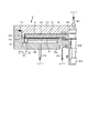
本発明の実施の形態の一例である成膜装置について、図1〜図9を参照して説明する。この成膜装置は、図1(図3のI−I’線に沿った断面図)に示すように平面形状が概ね円形である扁平な真空容器1と、この真空容器1内に設けられ、当該真空容器1の中心に回転中心を有する載置台である回転テーブル2と、を備えている。真空容器1は天板11が容器本体12から着脱できるように構成されている。天板11は、真空容器1内が減圧されることにより、容器本体12の上面の周縁部にリング状に設けられたシール部材例えばOリング13を介して容器本体12側に引きつけられて気密状態を維持しているが、容器本体12から分離するときには図示しない駆動機構により上方に持ち上げられる。
A film forming apparatus which is an example of an embodiment of the present invention will be described with reference to FIGS. As shown in FIG. 1 (a cross-sectional view taken along line II ′ in FIG. 3), the film forming apparatus is provided in a
回転テーブル2は、中心部にて円筒形状のコア部21に固定され、このコア部21は、鉛直方向に伸びる回転軸22の上端に固定されている。回転軸22は真空容器1の底面部14を貫通し、その下端が当該回転軸22を鉛直軸周りにこの例では時計方向に回転させる回転機構である駆動部23に取り付けられている。回転軸22及び駆動部23は、上面が開口した筒状のケース体20内に収納されている。このケース体20はその上面に設けられたフランジ部分が真空容器1の底面部14の下面に気密に取り付けられており、ケース体20の内部雰囲気と外部雰囲気との気密状態が維持されている。
The rotary table 2 is fixed to a
回転テーブル2の表面部には、図2及び図3に示すように、回転方向(周方向)に沿って複数枚例えば5枚の基板である半導体ウエハ(以下「ウエハ」という)Wを載置するための円形状の凹部24が設けられており、平面で見た時の回転テーブル2の回転中心と当該回転中心側の凹部24の端部との間の距離及び回転テーブル2の外縁部と当該外縁部側の凹部24の端部との間の距離は、夫々例えば160mm及び30mmとなっている。このウエハWは、直径寸法が例えば300mmとなっている。尚、図3には便宜上1個の凹部24だけにウエハWを描いてある。
As shown in FIGS. 2 and 3, a plurality of, for example, five semiconductor wafers (hereinafter referred to as “wafers”) W are placed on the surface of the
凹部24は、直径がウエハWの直径よりも僅かに例えば4mm大きく、またその深さはウエハWの厚みと同程度に設定されている。従ってウエハWを凹部24に落とし込むと、ウエハWの表面と回転テーブル2の表面(ウエハWが載置されない領域)とが揃うことになる。凹部24の底面には、ウエハWの裏面を支えて当該ウエハWを昇降させるための例えば後述する3本の昇降ピンが貫通する貫通孔(図示せず)が形成されている。凹部24は、ウエハWを位置決めして回転テーブル2の回転に伴う遠心力により飛び出さないようにするためのものであり、本発明の基板載置領域に相当する部位である。
The
図2及び図3に示すように、回転テーブル2における凹部24の通過領域と各々対向する位置には、各々例えば石英からなる第1の反応ガスノズル31及び第2の反応ガスノズル32と、2本の分離ガスノズル41、42と、が真空容器1の周方向(回転テーブル2の回転方向)に互いに間隔をおいて放射状に配置されている。この例では、後述の搬送口15から見て時計回り(回転テーブル2の回転方向)に第2の反応ガスノズル32、分離ガスノズル41、第1の反応ガスノズル31及び分離ガスノズル42がこの順番で配列されており、これらのノズル31、32、41、42は、例えば真空容器1の外周壁から回転テーブル2の回転中心に向かってウエハWに対向して水平に伸びるように各々取り付けられている。各ノズル31、32、41、42の基端部であるガス導入ポート31a、32a、41a、42aは、真空容器1の外周壁を貫通している。これら反応ガスノズル31、32は、夫々第1の反応ガス供給部、第2の反応ガス供給部をなし、分離ガスノズル41、42は、各々分離ガス供給部をなしている。
As shown in FIG. 2 and FIG. 3, there are a first
第1の反応ガスノズル31は、流量調整バルブなどを介して、Si(シリコン)を含む第1の反応ガス例えばジイソプロピルアミノシランガスまたはBTBAS(ビスターシャルブチルアミノシラン、SiH2(NH−C(CH3)3)2)ガスのガス供給源(いずれも図示せず)に接続されている。第2の反応ガスノズル32は、同様に流量調整バルブなどを介して、第2の反応ガス例えばO3(オゾン)ガスとO2(酸素)ガスとの混合ガスのガス供給源(いずれも図示せず)に接続されている。これら第1の反応ガス及び第2の反応ガスの流量は、夫々例えば10〜1000sccm、1〜10slm程度に設定される。これら第1の反応ガス及び第2の反応ガスとしては、上で挙げたガス以外にも、以下の表に示すガスを用いて、この表の右側の欄に示す薄膜を成膜しても良いし、これら反応ガスを組み合わせて前記薄膜の混合物や積層体を形成しても良い。更に、第2の反応ガスとしてO3ガスを用いる場合には、このO3ガスに代えて、あるいはO3ガスと共に、酸素(O)プラズマを用いても良い。
(表)

(table)
分離ガスノズル41、42は、夫々流量調整バルブなどを介して、分離ガスであるN2(窒素)ガスのガス供給源(いずれも図示せず)に接続されている。これら分離ガスノズル41、42から吐出される分離ガスの流量は、各々例えば1〜20slm程度に設定される。尚、以下においては、便宜上第2の反応ガスをO3ガスとして説明する。
The
反応ガスノズル31、32には、ガス吐出孔33が真下を向いてノズルの長さ方向に亘って例えば10mmの間隔をおいて等間隔に配列されている。反応ガスノズル31、32の下方領域は、夫々Si含有ガスをウエハWに吸着させるための第1の処理領域P1及びウエハWに吸着したSi含有ガスとO3ガスとを反応させるための第2の処理領域P2となる。反応ガスノズル31、32は、処理領域P1、P2における天井面45から離間してウエハWの近傍に夫々設けられている。
In the
分離ガスノズル41、42は、第1の処理領域P1と第2の処理領域P2とを分離する分離領域Dを形成するためのものであり、当該分離ガスノズル41、42の長さ方向に沿うように、例えば開口径がφ0.3やφ0.5mmのガス吐出孔33が下面側に複数箇所に形成されている。このガス吐出孔33については後で詳述するが、回転テーブル2の中心側では、外縁側よりもガス吐出孔33、33間の離間寸法(ピッチ)を広くしている。これら各ノズル31、32、41、42は、回転テーブル2の中心側における凹部24の外縁よりも、先端部が例えば20mmや40mm程度当該中心側に突き出るように配置されている。
The
分離領域Dにおける真空容器1の天板11には図2及び図3に示すように、回転テーブル2の回転中心を中心としかつ真空容器1の内周壁の近傍に沿って描かれる円を周方向に分割してなる、平面形状が扇型で下方に突出した凸状部4が設けられている。分離ガスノズル41、42は、この凸状部4における前記円の周方向中央にて当該円の半径方向に伸びるように形成された溝部43内に収められている。回転テーブル2の回転中心と、この凸状部4を上側から見た時の前記回転中心から伸びる当該凸状部4の2つの外縁とのなす角度θは、図5に示すように例えば60°となっている。また、凸状部4の下面と回転テーブル2上のウエハWとの間の距離tは、図6に示すように例えば4mmとなっている。尚、図5では凸状部4を一点鎖線で模式的に示している。
As shown in FIGS. 2 and 3, the
分離ガスノズル41、42における前記周方向両側には、前記凸状部4の下面である例えば平坦な低い天井面44(第1の天井面)が存在し、この天井面44の前記周方向両側には、当該天井面44よりも高い天井面45(第2の天井面)が存在することになる。この凸状部4の役割は、図4に示すように、当該凸状部4と回転テーブル2との間に狭隘な領域である分離空間を形成して、この領域から処理領域P1、P2側に分離ガスを吐出させ、当該分離ガスの流れによって第1の反応ガス及び第2の反応ガスの分離領域Dへの侵入を阻止することにある。
For example, a flat low ceiling surface 44 (first ceiling surface) that is the lower surface of the
即ち、回転テーブル2を回転させると、この回転テーブル2の回転に連れられて、回転方向上流側の雰囲気(反応ガス)が下流側の分離領域Dに引き込まれようとする。また、分離ガスと反応ガスとが互いに接触していると、当該分離ガスの雰囲気を介して反応ガスが拡散してこようとし、更に両ガスの間で圧力差に応じたガス流が形成されようとする。そこで、この実施の形態では、分離領域Dにおける分離ガスの流速について、(1)回転テーブル2の回転により引き込まれる雰囲気の流速に打ち勝つように、また(2)反応ガスが分離領域D中に多少拡散しても、実質侵入できない状態で分離領域Dから処理領域P1、P2に分離ガスのガス流が形成されるように設定している。ここで、以下に説明するプロセス条件では、種々行った実験などにより、分離領域Dによる分離機能を確保するためには、後述の図11にも示すように、(1)の項目が支配的になる(影響が大きい)ことが分かった。従って、各々の分離領域Dにおいて、回転テーブル2の回転によって引き込まれる雰囲気の流速に対して、各々の分離領域Dから前記狭隘な空間を介して処理領域P1、P2に吐出される分離ガスの流速の方が大きくなるようにしている。
That is, when the
具体的には、回転テーブル2の回転に連れられて下流側に引き込まれてくる雰囲気の流速は、回転テーブル2の回転速度(周速度)と同程度か、あるいは周速度よりも遅くなると考えられる。そのため、既述の狭隘な空間から処理領域P1、P2に吐出される分離ガスの流速について、分離領域Dの分離機能が確保されるように、前記周速度よりも速い速度に設定している。この時、既述のように、第1の反応ガス及び第2の反応ガスの流量が分離ガスの流量に比べて極めて少なく、また回転テーブル2の回転数が240rpm程度と速い。そのため、反応ガスノズル31、32から真空容器1内に吐出された反応ガスは、回転テーブル2上において公転しているある一つのウエハWからは、いわばほとんど静止しているように見えると考えられる。従って、反応ガスノズル31、32から吐出するこれら反応ガスの流速についてはゼロと近似している。また、回転テーブル2の回転により分離領域Dに引き込まれようとする雰囲気は、真空容器1内の部材や後述の排気口61(62)に向かう排気流などにより抵抗を受けるので、実際には回転テーブル2の周速度よりも遅い流速となるが、ここでは計算を簡略化するため、更には雰囲気の流速に対して分離領域Dから処理領域P1、P2側に吹き出す分離ガスの流速にマージンを設けるため、既述のように回転テーブル2の周速度と同程度の流速で通流するものして計算している。
Specifically, it is considered that the flow velocity of the atmosphere drawn downstream by the rotation of the
ここで、回転テーブル2の周速度は、回転テーブル2の中心側よりも外縁側の方が速く、直径寸法が300mmのウエハWを半径方向に載置する回転テーブル2では、中心側の周速度に対して外縁側の周速度が3倍程度となる。そのため、分離領域Dから処理領域P1、P2に吐出される分離ガスの流速について、回転テーブル2の中心側から外縁側に亘って同じ値に設定すると、即ち周速度の最も速い回転テーブル2の最外周において分離領域Dの分離機能が確保されるように分離ガスの流速を揃えると、回転テーブル2の中心側では分離ガスが過剰に供給されることになる。従って、この発明では、分離領域Dから処理領域P1、P2に吐出する分離ガスの流速について、当該分離領域Dによる分離機能を確保しながら分離ガスの消費量をできるだけ抑えるために、回転テーブル2の周縁側よりも中心側において遅くなるように(中心側では周縁側よりも分離ガスの供給量が少なくなるように)設定している。このような流速となるように分離ガスの流量を具体的に設定する手法について、回転テーブル2の中心側から外縁側に向かって分離領域Dを2つの領域A1、A2に模式的に区画して、領域A1において領域A2よりも分離ガスの流量を少なく設定する方法を例に挙げて以下に説明する。
Here, the peripheral speed of the
先ず、図5に示すように、例えば回転テーブル2上の5つのウエハWの各々の中心位置を結ぶ円状のラインに符号「L1」を付す。また、ラインL1よりも回転テーブル2の中心側の空間を領域A1(A1:ラインL1を通る鉛直面、後述の突出部5の外周面、回転テーブル2上のウエハW及び凸状部4で囲まれる領域)、当該ラインL1よりも周縁側の空間を領域A2(A2:ラインL1を通る鉛直面、回転テーブル2の外縁を通る鉛直面、回転テーブル2上のウエハW及び凸状部4で囲まれる領域)と呼ぶことにする。そして、図7に示すように、これら各領域A1、A2において、上流側及び下流側の処理領域P1、P2に夫々連通する側面S1、S2の面積を求める。また、例えば回転テーブル2の回転数を240rpmに設定した場合において、各領域A1、A2を回転テーブル2が通過する最大周速度即ちラインL1における周速度(領域A1の最大周速度)及び回転テーブル2の外周縁における周速度(領域A2の最大周速度)を計算する。尚、図7では、各領域A1、A2の両側面のうち回転テーブル2の回転方向上流側について示しており、また凸状部4については省略している。
First, as shown in FIG. 5, for example, a symbol “L1” is attached to a circular line connecting the center positions of the five wafers W on the
次いで、各々の分離領域Dに供給する分離ガスの流量を設定し、例えば処理圧力が1067Pa(8Torr)及び処理温度が350℃の処理条件において、この分離ガスが真空容器1内で占める体積を求める。そして、この分離ガスのうち一部が領域A1の側面S1、S1から処理領域P1、P2に向かって吐出され、残りの分離ガスが領域A2の側面S2、S2から処理領域P1、P2に吐出されるものとして、各領域A1、A2に振り分ける分離ガスの流量の比率を設定する。続いて、前記処理条件において、各々の領域A1、A2における回転テーブル2の最大周速度よりも、これら領域A1、A2の側面S1、S2から吐出する分離ガスの流速の方が夫々僅かに大きくなるように、分離領域Dに供給する分離ガスの流量と前記比率とを種々変えて計算を行う。
Next, the flow rate of the separation gas supplied to each separation region D is set. For example, the volume occupied by the separation gas in the
こうして計算を行った結果、各領域A1、A2における回転テーブル2の最大周速度は夫々約7.8m/s及び約12m/sとなった。また、各々の分離領域Dに供給する分離ガスの流量は例えば10slmとなり、各領域A1、A2に振り分ける分離ガスの流量比は1:2となった。尚、領域A2については、前記側面S2以外にも、回転テーブル2の外周縁よりも外周側の領域(当該回転テーブル2と屈曲部46との間の領域)を介して、分離ガスが分離領域Dから僅かに吐出されると考えられる。そのため、当該外周側の領域を介して分離ガスが吐出する流量として、領域A2に供給されるガス流量のうち例えば少量を差し引いて前記計算を行った。また、分離領域Dに対して上流側から引き込まれようとする雰囲気の流速よりも当該分離領域Dから吐出する分離ガスの流速の方が速くなるように分離ガスの供給流量を設定しているので、分離領域Dの下流側からの分離領域Dへの雰囲気の侵入は当然に阻止される。
As a result of the calculation, the maximum peripheral speed of the
ここで、分離ガス供給管51から中心部領域Cに対してN2ガスを供給しているが、このN2ガスは当該中心部領域Cを介してガスの混合が行われることを防止するためのものである。中心部領域Cに供給されるN2ガスの流量は、例えば1slmであり、分離ガスノズル41、42から供給されるN2ガスの流量の1/1〜1/10程度となる。そのため、この中心部領域Cから各々の分離領域Dに向かう分離ガスは、分離ガスノズル41(42)から供給される各々のガス流量と比べて1/6以下の極めて少ない流量となる。即ち、中心部領域Cに供給される分離ガスは、当該中心部領域Cから周方向に亘って外側に向かって通流するので、各々の分離領域Dには1/6(θ=60°/360°)の分離ガスが進入しようとする。しかし、分離領域Dでは回転テーブル2の表面に近接して低い天井面44が形成され、一方処理領域P1、P2側では当該天井面44よりも高い天井面45が形成されているので、当該分離領域Dには中心部領域Cからの分離ガスが入り込みにくくなっている。従って、分離ガス供給管51から真空容器1内に供給されるN2ガスの流量を考慮しても、回転テーブル2上においてウエハWの中心部側よりも外縁側の方がN2ガスの流量が多くなる。
Here, the N2 gas is supplied from the separation
以上において説明したN2ガス流量となるように、即ち各領域A1、A2に供給される分離ガスの流量比が1:2となるように、分離ガスノズル41、42には既述のガス吐出孔33が各々配置されている。具体的には、図8に示すように、領域A1では例えばガス吐出孔33の配列間隔(ピッチ)uが20mmとなるように配置され、領域A2では配列間隔uが10mmとなっている。
The gas discharge holes 33 described above are provided in the
ここで、ガス吐出孔33の配列間隔uを分離ガスノズル41、42の長さ方向において同じ間隔となるように設定した場合(u:10mm)、即ち各領域A1、A2に供給される分離ガスの流量比が1:1の場合、同様に各々の領域A1、A2において側面S1、S2から夫々吐出する分離ガスの流速の方が前記最大周速度よりも夫々僅かに大きくなるように既述の処理条件において計算したところ、分離ガスの流量は12.5slmとなった。従って、各領域A1、A2に対して分離ガスの流量を既述のように振り分けることにより、2つの分離領域Dを合計すると5slmもの分離ガスを節約できることが分かった。
Here, when the arrangement interval u of the gas discharge holes 33 is set to be the same interval in the length direction of the
続いて、真空容器1の説明に戻ると、天板11の下面には、図9に示すように回転テーブル2におけるコア部21よりも外周側の部位と対向するようにかつ当該コア部21の外周に沿って突出部5が設けられている。この突出部5は凸状部4における前記回転中心側の部位と連続して形成されており、その下面が凸状部4の下面(天井面44)と同じ高さに形成されている。このコア部21の外周面と各ノズル31、32、41、42の先端部との間の距離は、例えば50mmとなっている。図2及び図3は、前記天井面45よりも低くかつ分離ガスノズル41、42よりも高い位置にて天板11を水平に切断して示している。
Subsequently, returning to the description of the
真空容器1の天板11の下面、つまり回転テーブル2のウエハ載置領域(凹部24)から見た天井面は既述のように第1の天井面44とこの天井面44よりも高い第2の天井面45とが周方向に存在するが、図1では、高い天井面45が設けられている領域についての縦断面を示しており、図9では、低い天井面44が設けられている領域についての縦断面を示している。扇型の凸状部4の周縁部(真空容器1の外縁側の部位)は図2及び図9に示されているように回転テーブル2の外端面に対向するようにL字型に屈曲して屈曲部46を形成している。扇型の凸状部4は天板11側に設けられていて、容器本体12から取り外せるようになっていることから、前記屈曲部46の外周面と容器本体12との間には僅かに隙間がある。この屈曲部46も凸状部4と同様に両側から反応ガスが侵入することを防止して、両反応ガスの混合を防止する目的で設けられており、屈曲部46の内周面と回転テーブル2の外端面との隙間、及び屈曲部46の外周面と容器本体12との隙間は、例えば回転テーブル2の表面に対する天井面44の高さと同様の寸法に設定されている。
The lower surface of the
容器本体12の内周壁は、分離領域Dにおいては図9に示すように前記屈曲部46の外周面と接近して垂直面に形成されているが、分離領域D以外の部位においては、図1に示すように例えば回転テーブル2の外端面と対向する部位から底面部14に亘って縦断面形状が矩形に切り欠かれて外方側に窪んだ構造になっている。この窪んだ部分における既述の第1の処理領域P1及び第2の処理領域P2に連通する領域を夫々第1の排気領域E1及び第2の排気領域E2と呼ぶことにすると、これらの第1の排気領域E1及び第2の排気領域E2の底部には、図1及び図3に示すように、夫々第1の排気口61及び第2の排気口62が形成されている。第1の排気口61及び第2の排気口62は、図1に示すように各々排気管63を介して真空排気機構である例えば真空ポンプ64に接続されている。なお図1中、65は圧力調整手段である。
As shown in FIG. 9, the inner peripheral wall of the container
前記回転テーブル2と真空容器1の底面部14との間の空間には、図1及び図9に示すように加熱手段であるヒータユニット7が設けられ、回転テーブル2を介して回転テーブル2上のウエハWをプロセス条件で決められた温度に加熱するようになっている。前記回転テーブル2の周縁付近の下方側には、回転テーブル2の上方空間から排気領域E1、E2に至るまでの雰囲気とヒータユニット7が置かれている雰囲気とを区画して回転テーブル2の下方領域へのガスの侵入を抑えるために、ヒータユニット7を全周に亘って囲むようにリング状のカバー部材71が設けられている。このカバー部材71は、回転テーブル2の外縁部及び当該外縁部よりも外周側を下方側から臨むように設けられた内側部材71aと、この内側部材71aと真空容器1の内壁面との間に設けられた外側部材71bと、を備えている。この外側部材71bは、既述の排気口61、62の上方側においてはこれら排気口61、62と回転テーブル2の上方領域とを連通させるために例えば円弧状に切りかかれて排気領域E1、E2をなし、屈曲部46の下方側においては上端面が当該屈曲部46に近接するように配置されている。
In the space between the
ヒータユニット7が配置されている空間よりも回転中心寄りの部位における底面部14は、回転テーブル2の下面の中心部付近におけるコア部21に接近するように上方側に突出して突出部12aをなしている。この突出部12aとコア部21との間は狭い空間になっており、また当該底面部14を貫通する回転軸22の貫通穴についてもその内周面と回転軸22との隙間が狭くなっていて、これら狭い空間は前記ケース体20内に連通している。そして前記ケース体20にはパージガスであるN2ガスを前記狭い空間内に供給してパージするためのパージガス供給管72が設けられている。また真空容器1の底面部14には、ヒータユニット7の下方側位置にて周方向の複数部位に、ヒータユニット7の配置空間をパージするためのパージガス供給管73が設けられている。このヒータユニット7と回転テーブル2との間には、当該ヒータユニット7が設けられた領域へのガスの侵入を抑えるために、既述の外側部材71bの内周壁から突出部12aの上端部との間を周方向に亘って接続する例えば石英からなる覆い部材7aが設けられている。
The
また真空容器1の天板11の中心部には分離ガス供給管51が接続されていて、天板11とコア部21との間の空間52に分離ガスであるN2ガスを供給するように構成されている。この空間52に供給された分離ガスは、前記突出部5と回転テーブル2との狭い隙間50を介して回転テーブル2のウエハ載置領域側の表面に沿って周縁に向けて吐出されることになる。この突出部5で囲まれる空間には分離ガスが満たされているので、第1の処理領域P1と第2の処理領域P2との間で回転テーブル2の中心部を介して反応ガス(Si含有ガス及びO3ガス)が混合することを防止している。
Further, a separation
更に真空容器1の側壁には図2、図3に示すように外部の搬送アーム10と回転テーブル2との間で基板であるウエハWの受け渡しを行うための搬送口15が形成されており、この搬送口15は図示しないゲートバルブにより開閉されるようになっている。また回転テーブル2におけるウエハ載置領域である凹部24はこの搬送口15に臨む位置にて搬送アーム10との間でウエハWの受け渡しが行われることから、回転テーブル2の下方側において当該受け渡し位置に対応する部位に、凹部24を貫通してウエハWを裏面から持ち上げるための受け渡し用の昇降ピン及びその昇降機構(いずれも図示せず)が設けられている。
Further, as shown in FIGS. 2 and 3, a
また、この成膜装置には、装置全体の動作のコントロールを行うためのコンピュータからなる制御部100が設けられており、この制御部100のメモリ内には後述の成膜処理を行うためのプログラムが格納されている。このプログラムは、ハードディスク、コンパクトディスク、光磁気ディスク、メモリカード、フレキシブルディスクなどの記憶媒体である記憶部101から制御部100内にインストールされる。
Further, the film forming apparatus is provided with a
次に、上述実施の形態の作用について説明する。先ず、図示しないゲートバルブを開き、外部から搬送アーム10により搬送口15を介してウエハWを回転テーブル2の凹部24内に受け渡す。この受け渡しは、凹部24が搬送口15に臨む位置に停止したときに凹部24の底面の貫通孔を介して真空容器の底部側から不図示の昇降ピンが昇降することにより行われる。このようなウエハWの受け渡しを回転テーブル2を間欠的に回転させて行い、回転テーブル2の5つの凹部24内に夫々ウエハWを載置する。続いてゲートバルブを閉じ、真空ポンプ64により真空容器1内を引き切りの状態にすると共に、回転テーブル2を例えば240rpmで時計回りに回転させながらヒータユニット7によりウエハWを例えば350℃に加熱する。次いで、反応ガスノズル31、32から夫々Si含有ガス及びO3ガスを例えば夫々100sccm、10slmで吐出すると共に、分離ガスノズル41、42から分離ガスであるN2ガスを例えば10slmで吐出し、分離ガス供給管51及びパージガス供給管72からもN2ガスを例えば夫々1〜3slm、10slmで吐出する。そして、圧力調整手段65により真空容器1内を予め設定した処理圧力例えば1067Pa(8Torr)に調整する。
Next, the operation of the above embodiment will be described. First, a gate valve (not shown) is opened, and the wafer W is transferred from the outside to the
回転テーブル2の回転により、ウエハWの表面には第1の処理領域P1においてSi含有ガスが吸着し、次いで第2の処理領域P2においてウエハW上に吸着したSi含有ガスが酸化され、薄膜成分である酸化シリコン膜の分子層が1層あるいは複数層形成されて反応生成物の成膜が行われる。そして、この反応生成物が積層されることによって、薄膜が形成される。この時、回転テーブル2の回転に連れられて、これら反応ガスが分離領域Dに侵入しようとする。しかし、既述のように各々の分離ガスノズル41、42のガス吐出孔33及び分離ガスの供給流量を設定していることから、これら反応ガスの分離領域Dへの侵入が阻止される。
The rotation of the
また、分離領域Dへの反応ガスの侵入を阻止するにあたって、既述のように分離ガスの供給量ができるだけ少なくなるように(回転テーブル2の中心側の供給量を外縁側よりも少なく)しているので、処理領域P1ではSi含有ガスの希釈が抑えられる。そのため、この処理領域P1では、ウエハWとSi含有ガスとの接触時間あるいはウエハWが接触するSi含有ガスの濃度が十分に長く(高く)保たれるので、ウエハWの表面に吸着するSi含有ガスの量がほぼ設定通りになる。また、同様に処理領域P2では分離ガスによるO3ガスの希釈が抑えられるので、ウエハW上に吸着したSi含有ガスが良好に酸化され、例えば膜中への不純物の残留が抑えられる。
In order to prevent the reaction gas from entering the separation region D, the supply amount of the separation gas is reduced as much as possible (the supply amount on the center side of the
そして、中心部領域Cにおいても分離ガスであるN2ガスを供給しているので、図10に示すように、Si含有ガスとO3ガス及び処理ガスとが互いに混合しないように各ガスが排気されることとなる。なお、回転テーブル2の下方側をN2ガスによりパージしているため、排気領域Eに流入したガスが回転テーブル2の下方側を潜り抜けて、例えばSi含有ガスがO3ガスの供給領域に流れ込むといったおそれは全くない。
Since the separation gas N2 gas is also supplied to the central region C, each gas is exhausted so that the Si-containing gas, the O3 gas, and the processing gas are not mixed with each other, as shown in FIG. It will be. Since the lower side of the
上述の実施の形態によれば、真空容器1内において分離領域Dを介して処理領域P1、P2をウエハWが順番に通過するように回転テーブル2を回転させるにあたり、回転テーブル2の中央側よりも周縁側の分離ガスの供給量が多くなるように分離ガスノズル41、42のガス吐出孔33を配置すると共に、分離領域Dから処理領域P1、P2側に吐出される分離ガスの流速について、各領域A1、A2における回転テーブル2の最大周速度よりも夫々僅かに速くなるように設定している。そのため、前記中央側において分離ガスの過剰な供給を抑えることができるので、分離領域Dによる分離機能を確保しながら、分離ガスの消費量を抑えることができる。従って、各反応ガスの希釈を抑えることができるので、ほぼ設定通りの成膜レートで薄膜を成膜できる。そのため、回転テーブル2の回転数を例えば240rpm程度に高速で回転させたり、あるいは処理圧力を例えば2666Pa(20Torr)程度に高く設定したりした場合であっても、ほぼ設定通りの高い成膜レートが得られるので、本発明の手法は、成膜レートの設定可能範囲を広げることによって、プロセスマージンを拡大させることができると言える。
According to the above-described embodiment, when the
また、分離ガスの消費量を抑えることにより、この分離ガスを排気する真空ポンプ64の負荷を抑えることができるので、高価な部材(真空ポンプ64)が不要になり、従って装置のコストを低減できる。更に、分離ガスの消費量を抑えることによって真空ポンプ64の排気能力に余裕が出てくる場合には、例えば133Pa(1Torr)程度に真空容器1内を高真空に設定して成膜処理を行うこともできる。更にまた、分離ガスの使用量が抑えられるので、当該分離ガスのコストも低減できる。
Further, since the load of the
更に、分離領域Dへ引き込まれようとする雰囲気の流速として、既述のように回転テーブル2の周速度を便宜的に用いているので、分離ガスの流量を簡単に計算できる。更にまた、分離ガスノズル41、42の各々の両側に狭隘な空間を形成しているので、分離領域Dに供給された分離ガスがいわば層流の状態で処理領域P1、P2に向かって通流していくため、既述のように流速の計算を簡単に行うことができる。
Further, as described above, the peripheral speed of the
ここで、図11は、分離領域Dへの外部の雰囲気(反応ガス)の侵入を阻止するために必要な分離ガスの流量について、回転テーブル2の回転数と、真空容器1内の圧力と、に応じて模式的に示したグラフである。回転テーブル2の回転数が速くなる程、当該回転テーブル2の回転に連れられて分離領域Dに侵入しようとする雰囲気の流速が速くなるので、当該雰囲気の分離領域Dへの侵入を阻止するために必要な分離ガスの流量についても多くなる。また、真空容器1内の圧力が高くなる程、当該真空容器1内に供給された分離ガスが膨張しなくなるので、同様に分離領域Dへの雰囲気の侵入を阻止するために必要な分離ガスの流量が多くなる。そのため、本発明のように中央部側の分離ガスの流量を周縁部側よりも少なくして分離ガスの消費量を抑える効果は、回転テーブル2の回転数が速い程、また真空容器1内の圧力が高い程、即ち高い成膜レートが得られる条件になる程、顕著になると言える。本発明が適用される好ましい処理条件は、回転テーブル2の回転数が120rpm以上、真空容器1内の圧力が133Pa(1Torr)以上である。尚、図11に一点鎖線で示すように、回転テーブル2の回転数が遅く、更に真空容器1内の圧力が低い条件では、ガス流速よりもガス拡散の方が支配的になる。即ち、分離領域Dに侵入しようとする雰囲気の流速よりも速い流速で当該分離領域Dから分離ガスを吐出させても、この分離ガスが分散している領域を介して前記雰囲気が拡散しようとする。そのため、本発明は既述の処理条件の場合に適用することが好ましい。
Here, FIG. 11 shows the number of rotations of the rotary table 2, the pressure in the
既述の例では、回転テーブル2の外縁側よりも中心側における分離ガスの供給量を少なくするにあたり、2つの領域A1、A2を設けたが、3つ以上であっても良い。図12は、回転テーブル2の中心側から外縁側に向かって3つの領域A1、A2、A3を設けた例を示している。これら領域A1、A2間の境界であるラインL2及び領域A2、A3間の境界であるラインL3は、例えば回転テーブル2の中央側から外縁側に向かってウエハWの端部から1/3の位置及び2/3の位置に夫々設けられる。そして、各領域A1、A2、A3において、分離ガスノズル41、42のガス吐出孔33における既述の配列間隔uは、夫々30mm、20mm、10mmに設定される。この場合には、3つの領域A1、A2、A3における回転テーブル2の最大周速度に合わせてガス流量を割り振ることができるので、分離ガスの消費量を更に低減できる。
In the example described above, two regions A1 and A2 are provided in order to reduce the supply amount of the separation gas on the center side rather than the outer edge side of the
また、図13に示すように、分離ガスノズル41、42のガス吐出孔33の配列間隔uについて、回転テーブル2の中心側から外縁側に向かうにつれて徐々に狭くなるように、いわばグラデーションを形成したように配列しても良い。即ち、回転テーブル2の中心側では配列間隔uを25mmに設定し、回転テーブル2の外周部では配列間隔uを5mmに設定する。そして、回転テーブル2の中心側から外縁側に向かうにつれて例えば1mmずつ配列間隔uが狭くなるようにガス吐出孔33が配置される。この場合には、回転テーブル2の半径方向における周速度に合わせてガス流量をきめ細かに割り振ることができるので、分離ガスの消費量を更に一層低減できる。
Also, as shown in FIG. 13, the so-called gradation is formed so that the arrangement interval u of the gas discharge holes 33 of the
以上の例では、分離ガスの供給量を割り振るにあたって、ガス吐出孔33の配列間隔uを調整したが、例えば図14に示すように、ガス吐出孔33の開口径を調整しても良い。図14は、分離ガスノズル41、42の長さ方向に亘って配列間隔uを等間隔に例えば10mmでガス吐出孔33を配置すると共に、回転テーブル2の中心側におけるガス吐出孔33の開口径を例えばφ0.19mm、外縁側におけるガス吐出孔33の開口径をφ0.27mmに設定した例を示している。即ち、回転テーブル2の中心側のガス吐出孔33の開口径と、回転テーブル2の外縁側のガス吐出孔33の開口径と、の比率を1:2にしている。尚、図14は、分離ガスノズル41、42を下方側から見た様子を模式的に示している。以下の図15も同様である。
In the above example, when the supply amount of the separation gas is allocated, the arrangement interval u of the gas discharge holes 33 is adjusted. For example, as shown in FIG. 14, the opening diameter of the gas discharge holes 33 may be adjusted. In FIG. 14, the gas discharge holes 33 are arranged at an equal interval of, for example, 10 mm over the length direction of the
更に、図15に示すように、分離ガスノズル41、42の長さ方向に亘って配列間隔uを等間隔に例えば10mmでガス吐出孔33を配置すると共に、ガス吐出孔33の開口径についても分離ガスノズル41、42の長さ方向に亘って揃えて、ガス吐出孔33の配置密度を回転テーブル2の中心側と外縁側とで変えても良い。図15では、回転テーブル2の中心側ではガス吐出孔33を一列に配置すると共に、外縁側ではガス吐出孔33を分離ガスノズル41、42の長さ方向に直交する方向に2列に配置した例を示している。また、回転テーブル2の中心側において外縁側よりも分離ガスの供給量を少なくするにあたり、ガス吐出孔33の配列間隔u、開口径及び配置密度を組み合わせて供給量を調整しても良い。
Further, as shown in FIG. 15, the gas discharge holes 33 are arranged at an equal interval of, for example, 10 mm over the length direction of the
また、分離ガスを供給するにあたって回転テーブル2の外縁側から中心側に向かって伸びるノズル41、42を設けたが、前記外縁側及び中心側において夫々分離ガスを供給する分離ガス供給部(ガス吐出孔あるいは概略円板状のガスシャワーヘッド)を例えば真空容器1の天井面に各々配置し、これら分離ガス供給部から供給される分離ガスの流量を互いに独立して調整しても良い。この場合には、これら分離ガス供給部から分離領域Dに供給された分離ガスは、処理領域P1、P2側に向かうにつれて、既述の狭隘な空間により上方側へのガス流れが規制されると共に回転テーブル2の半径方向に拡散し、当該半径方向に亘って処理領域P1、P2に吐出することになる。即ち、本発明は、真空容器1の天井面に例えばウエハWに対向するように設けられたガス供給部から供給される分離ガスについて、回転テーブル2の外縁側よりも内側の流量が少なくなるように設定しており、例えば既述の分離ガス供給管51から真空容器1の中心部に供給される分離ガスについては、前記「内側」に供給される分離ガスとは別のガスとしてみなしている。
Further, when supplying the separation gas, the
また、既述の例ではノズル31、32、41、42に対して回転テーブル2を回転させたが、回転テーブル2を静止させ、当該回転テーブル2に対してノズル31、32、41、42を回転させても良い。更に、反応ガスノズル31、32について、上面側、回転テーブル2の回転方向における両側面側及び中心部領域C側から各々の反応ガスノズル31、32を覆うように、即ち反応ガスノズル31、32の下面側が開口する概略箱型のカバーを各々設けて、処理領域P1、P2への分離ガスの拡散を抑えるようにしても良い。なお分離ガスとしては、窒素(N2)ガスに限られずアルゴン(Ar)ガスなどの不活性ガスなどを用いても良い。
In the above-described example, the rotary table 2 is rotated with respect to the
W ウエハ
1 真空容器
2 回転テーブル
4 凸状部
D 分離領域
24 凹部
31 第1の反応ガスノズル
32 第2の反応ガスノズル
41、42 分離ガスノズル
33 吐出孔
P1 処理領域
P2 処理領域
Claims (5)
真空容器内に設けられ、基板を載置するための基板載置領域を備えた載置台と、
前記基板載置領域に載置された基板に対して前記複数種類の反応ガスを夫々供給するために、前記真空容器の周方向に互いに離間して設けられた複数の反応ガス供給部と、
これら反応ガスが夫々供給される処理領域同士の雰囲気を分離するために、各々の処理領域同士の間に設けられた分離領域と、
この分離領域に対して前記基板載置領域における真空容器の中央側及び周縁側に各々分離ガスを供給すると共に、前記中央側よりも前記周縁側における分離ガスの供給量が多くなるように設けられた分離ガス供給部と、
前記分離領域において前記中央側と前記周縁側との間に亘って当該分離領域から処理領域側に向かって分離ガスが流れるように、狭隘な空間を前記載置台との間に形成するための天井面と、
前記真空容器内を真空排気するための真空排気機構と、
前記複数の反応ガス供給部及び分離領域に対して前記載置台を相対的に回転させるための回転機構と、を備えたことを特徴とする成膜装置。 In a film forming apparatus for forming a thin film by repeating a cycle in which a plurality of types of reaction gases are sequentially supplied to a substrate in a vacuum atmosphere,
A mounting table provided in a vacuum vessel and provided with a substrate mounting region for mounting a substrate;
A plurality of reaction gas supply units provided to be spaced apart from each other in the circumferential direction of the vacuum vessel in order to supply the plurality of types of reaction gases to the substrate placed in the substrate placement region;
In order to separate the atmosphere of the processing regions supplied with these reaction gases, respectively, a separation region provided between the processing regions;
A separation gas is supplied to the separation region on the central side and the peripheral side of the vacuum vessel in the substrate mounting region, and the supply amount of the separation gas on the peripheral side is larger than that on the central side. Separated gas supply unit,
A ceiling for forming a narrow space between the separation area and the mounting table so that the separation gas flows from the separation area to the processing area side between the central side and the peripheral side. Surface,
An evacuation mechanism for evacuating the vacuum container;
A film forming apparatus comprising: a rotation mechanism for rotating the mounting table relative to the plurality of reaction gas supply units and the separation region.
このガスノズルには、基板載置領域に向かって分離ガスを吐出するための複数のガス吐出孔が当該ガスノズルの長さ方向に沿って互いに間隔をおいて配置され、
前記ガス吐出孔は、前記中央側よりも前記周縁側の分離ガスの供給量が多くなるように、前記ガス吐出孔間の間隔寸法、前記ガス吐出孔の開口径及び前記ガス吐出孔の配置密度の少なくとも1つが設定されていることを特徴とする請求項1に記載の成膜装置。 The separation gas supply unit is provided to face the substrate placement region, and includes a gas nozzle that extends between the center side and the peripheral side,
In this gas nozzle, a plurality of gas discharge holes for discharging the separation gas toward the substrate mounting region are arranged at intervals from each other along the length direction of the gas nozzle,
The gas discharge holes have a gap dimension between the gas discharge holes, an opening diameter of the gas discharge holes, and an arrangement density of the gas discharge holes so that the supply amount of the separation gas on the peripheral side is larger than the central side. The film forming apparatus according to claim 1, wherein at least one of the following is set.
真空容器内に設けられた載置台の基板載置領域に基板を載置する工程と、
前記真空容器内を真空排気する工程と、
次いで、前記基板載置領域に対して、前記真空容器の周方向に互いに離間して設けられた複数の反応ガス供給部から、前記複数種類の反応ガスを夫々供給する工程と、
これら反応ガスが夫々供給される処理領域同士の間に設けられた分離領域に対して、分離ガス供給部から、前記基板載置領域における真空容器の中央側よりも周縁側における供給量が多くなるように分離ガスを供給する工程と、
前記分離領域において天井面と前記載置台との間に形成された狭隘な空間を介して、前記中央側と前記周縁側との間に亘って当該分離領域から処理領域側に向かって分離ガスを吐出させて、処理領域同士の雰囲気を分離する工程と、
前記複数の反応ガス供給部及び分離領域に対して前記載置台を相対的に回転させ、前記分離領域を介して前記複数の処理領域に基板を順番に位置させる工程と、を含むことを特徴とする成膜方法。 In a film forming method for forming a thin film by repeating a cycle in which a plurality of types of reaction gases are sequentially supplied to a substrate in a vacuum atmosphere,
A step of placing a substrate on a substrate placement region of a placement table provided in a vacuum vessel;
Evacuating the inside of the vacuum vessel;
Next, supplying the plurality of types of reaction gases to the substrate placement region from a plurality of reaction gas supply units provided apart from each other in the circumferential direction of the vacuum vessel;
With respect to the separation region provided between the processing regions to which these reaction gases are respectively supplied, the supply amount on the peripheral side is larger than the central side of the vacuum vessel in the substrate mounting region from the separation gas supply unit. A step of supplying a separation gas,
Through the narrow space formed between the ceiling surface and the mounting table in the separation region, separation gas is passed from the separation region toward the processing region side between the center side and the peripheral side. Discharging and separating the atmosphere between the processing regions;
Rotating the mounting table relative to the plurality of reaction gas supply units and the separation region, and sequentially positioning the substrate in the plurality of processing regions via the separation region. A film forming method.
前記順番に位置させる工程において、前記複数の反応ガス供給部及び分離領域に対して前記載置台を相対的に回転させる回転数は、20rpm以上であることを特徴とする請求項3に記載の成膜方法。 The pressure in the vacuum vessel is 133 Pa or more,
4. The composition according to claim 3, wherein in the step of sequentially positioning, the number of rotations for rotating the mounting table relative to the plurality of reaction gas supply units and the separation region is 20 rpm or more. Membrane method.
前記コンピュータプログラムは、請求項3または4に記載の成膜方法を実施するようにステップが組まれていることを特徴とする記憶媒体。 In a storage medium storing a computer program used in a film forming apparatus for forming a thin film by repeating a cycle of supplying a plurality of types of reaction gases to a substrate in a vacuum container in order several times,
A storage medium characterized in that the computer program includes steps so as to implement the film forming method according to claim 3 or 4.
Priority Applications (5)
| Application Number | Priority Date | Filing Date | Title |
|---|---|---|---|
| JP2010227624A JP2012084598A (en) | 2010-10-07 | 2010-10-07 | Film deposition device, film deposition method, and storage medium |
| US13/238,366 US20120088030A1 (en) | 2010-10-07 | 2011-09-21 | Film forming apparatus, film forming method, and recording medium |
| KR1020110101699A KR20120036281A (en) | 2010-10-07 | 2011-10-06 | Film forming apparatus, film forming method, and recording medium |
| TW100136206A TW201250047A (en) | 2010-10-07 | 2011-10-06 | Film forming apparatus, film forming method, and recording medium |
| CN2011103066295A CN102443782A (en) | 2010-10-07 | 2011-10-08 | Film forming apparatus and film forming method |
Applications Claiming Priority (1)
| Application Number | Priority Date | Filing Date | Title |
|---|---|---|---|
| JP2010227624A JP2012084598A (en) | 2010-10-07 | 2010-10-07 | Film deposition device, film deposition method, and storage medium |
Publications (1)
| Publication Number | Publication Date |
|---|---|
| JP2012084598A true JP2012084598A (en) | 2012-04-26 |
Family
ID=45925347
Family Applications (1)
| Application Number | Title | Priority Date | Filing Date |
|---|---|---|---|
| JP2010227624A Pending JP2012084598A (en) | 2010-10-07 | 2010-10-07 | Film deposition device, film deposition method, and storage medium |
Country Status (5)
| Country | Link |
|---|---|
| US (1) | US20120088030A1 (en) |
| JP (1) | JP2012084598A (en) |
| KR (1) | KR20120036281A (en) |
| CN (1) | CN102443782A (en) |
| TW (1) | TW201250047A (en) |
Cited By (5)
| Publication number | Priority date | Publication date | Assignee | Title |
|---|---|---|---|---|
| JP2016100396A (en) * | 2014-11-19 | 2016-05-30 | 東京エレクトロン株式会社 | Nozzle and substrate processing apparatus using the same |
| JP2017212246A (en) * | 2016-05-23 | 2017-11-30 | 東京エレクトロン株式会社 | Deposition device |
| JP2017212244A (en) * | 2016-05-23 | 2017-11-30 | 東京エレクトロン株式会社 | Deposition method |
| JP2018152427A (en) * | 2017-03-10 | 2018-09-27 | 東京エレクトロン株式会社 | Deposition equipment |
| JP2022161543A (en) * | 2021-04-09 | 2022-10-21 | 東京エレクトロン株式会社 | Design method for gas holes and design device for gas holes |
Families Citing this family (11)
| Publication number | Priority date | Publication date | Assignee | Title |
|---|---|---|---|---|
| JP5131240B2 (en) * | 2009-04-09 | 2013-01-30 | 東京エレクトロン株式会社 | Film forming apparatus, film forming method, and storage medium |
| JP5886730B2 (en) * | 2012-11-26 | 2016-03-16 | 東京エレクトロン株式会社 | Film formation method, program for the film formation method, recording medium recording the program, and film formation apparatus |
| JP6159143B2 (en) * | 2013-05-10 | 2017-07-05 | 株式会社日立国際電気 | Semiconductor device manufacturing method, substrate processing apparatus, and program |
| JP6305314B2 (en) * | 2014-10-29 | 2018-04-04 | 東京エレクトロン株式会社 | Film forming apparatus and shower head |
| JP6330623B2 (en) * | 2014-10-31 | 2018-05-30 | 東京エレクトロン株式会社 | Film forming apparatus, film forming method, and storage medium |
| CN109898072B (en) * | 2019-01-31 | 2021-05-18 | 长江存储科技有限责任公司 | Semiconductor processing apparatus |
| CN109881181B (en) * | 2019-01-31 | 2021-05-18 | 长江存储科技有限责任公司 | Semiconductor processing equipment |
| CN109722651B (en) * | 2019-02-18 | 2021-03-23 | 长江存储科技有限责任公司 | Thin film deposition apparatus and gas supply device |
| JP7037526B2 (en) * | 2019-09-10 | 2022-03-16 | 株式会社Kokusai Electric | Substrate processing equipment, semiconductor equipment manufacturing methods and programs |
| JP6987821B2 (en) * | 2019-09-26 | 2022-01-05 | 株式会社Kokusai Electric | Substrate processing equipment, semiconductor equipment manufacturing methods and programs |
| CN113846315B (en) * | 2021-09-27 | 2022-08-02 | 华中科技大学 | Spatially isolated atomic layer deposition apparatus |
Citations (2)
| Publication number | Priority date | Publication date | Assignee | Title |
|---|---|---|---|---|
| JP2010153805A (en) * | 2008-11-19 | 2010-07-08 | Tokyo Electron Ltd | Film deposition apparatus, cleaning method for the same, and computer storage medium for storing program |
| JP2010219125A (en) * | 2009-03-13 | 2010-09-30 | Tokyo Electron Ltd | Film forming device |
Family Cites Families (1)
| Publication number | Priority date | Publication date | Assignee | Title |
|---|---|---|---|---|
| JPS6245029A (en) * | 1985-08-22 | 1987-02-27 | Matsushita Electric Ind Co Ltd | Thin film production equipment and thin film removal equipment |
-
2010
- 2010-10-07 JP JP2010227624A patent/JP2012084598A/en active Pending
-
2011
- 2011-09-21 US US13/238,366 patent/US20120088030A1/en not_active Abandoned
- 2011-10-06 TW TW100136206A patent/TW201250047A/en unknown
- 2011-10-06 KR KR1020110101699A patent/KR20120036281A/en not_active Ceased
- 2011-10-08 CN CN2011103066295A patent/CN102443782A/en active Pending
Patent Citations (2)
| Publication number | Priority date | Publication date | Assignee | Title |
|---|---|---|---|---|
| JP2010153805A (en) * | 2008-11-19 | 2010-07-08 | Tokyo Electron Ltd | Film deposition apparatus, cleaning method for the same, and computer storage medium for storing program |
| JP2010219125A (en) * | 2009-03-13 | 2010-09-30 | Tokyo Electron Ltd | Film forming device |
Cited By (7)
| Publication number | Priority date | Publication date | Assignee | Title |
|---|---|---|---|---|
| JP2016100396A (en) * | 2014-11-19 | 2016-05-30 | 東京エレクトロン株式会社 | Nozzle and substrate processing apparatus using the same |
| US10472719B2 (en) | 2014-11-19 | 2019-11-12 | Tokyo Electron Limited | Nozzle and substrate processing apparatus using same |
| JP2017212246A (en) * | 2016-05-23 | 2017-11-30 | 東京エレクトロン株式会社 | Deposition device |
| JP2017212244A (en) * | 2016-05-23 | 2017-11-30 | 東京エレクトロン株式会社 | Deposition method |
| JP2018152427A (en) * | 2017-03-10 | 2018-09-27 | 東京エレクトロン株式会社 | Deposition equipment |
| JP2022161543A (en) * | 2021-04-09 | 2022-10-21 | 東京エレクトロン株式会社 | Design method for gas holes and design device for gas holes |
| JP7582748B2 (en) | 2021-04-09 | 2024-11-13 | 東京エレクトロン株式会社 | Gas hole design method and gas hole design device |
Also Published As
| Publication number | Publication date |
|---|---|
| CN102443782A (en) | 2012-05-09 |
| US20120088030A1 (en) | 2012-04-12 |
| TW201250047A (en) | 2012-12-16 |
| KR20120036281A (en) | 2012-04-17 |
Similar Documents
| Publication | Publication Date | Title |
|---|---|---|
| JP2012084598A (en) | Film deposition device, film deposition method, and storage medium | |
| JP5062143B2 (en) | Deposition equipment | |
| JP5195175B2 (en) | Film forming apparatus, film forming method, and storage medium | |
| JP5253932B2 (en) | Film forming apparatus, substrate processing apparatus, film forming method, and storage medium | |
| JP5195174B2 (en) | Film forming apparatus and film forming method | |
| JP5062144B2 (en) | Gas injector | |
| JP5310512B2 (en) | Substrate processing equipment | |
| JP5141607B2 (en) | Deposition equipment | |
| JP5093162B2 (en) | Film forming apparatus, film forming method, and storage medium | |
| JP5375853B2 (en) | Film forming apparatus, film forming method, and storage medium | |
| JP5310283B2 (en) | Film forming method, film forming apparatus, substrate processing apparatus, and storage medium | |
| JP5195676B2 (en) | Film forming apparatus, substrate processing apparatus, film forming method, and storage medium | |
| TWI506159B (en) | Film forming device | |
| JP5056735B2 (en) | Deposition equipment | |
| JP5253933B2 (en) | Film forming apparatus, substrate processing apparatus, film forming method, and storage medium | |
| JP5280964B2 (en) | Film forming apparatus, substrate processing apparatus, film forming method, and storage medium | |
| JP5083193B2 (en) | Film forming apparatus, film forming method, and storage medium | |
| JP5262452B2 (en) | Film forming apparatus and substrate processing apparatus | |
| JP5195176B2 (en) | Deposition equipment | |
| JP2010126797A (en) | Film deposition system, semiconductor fabrication apparatus, susceptor for use in the same, program and computer readable storage medium | |
| JP2011151387A (en) | Film deposition apparatus and film deposition method | |
| JP5093078B2 (en) | Deposition equipment | |
| JP2013055356A (en) | Substrate processing apparatus, substrate processing method, and storage medium | |
| JP5403113B2 (en) | Deposition equipment | |
| JP2010129983A (en) | Film deposition apparatus |
Legal Events
| Date | Code | Title | Description |
|---|---|---|---|
| A621 | Written request for application examination |
Free format text: JAPANESE INTERMEDIATE CODE: A621 Effective date: 20130605 |
|
| A977 | Report on retrieval |
Free format text: JAPANESE INTERMEDIATE CODE: A971007 Effective date: 20140122 |
|
| A131 | Notification of reasons for refusal |
Free format text: JAPANESE INTERMEDIATE CODE: A131 Effective date: 20140204 |
|
| A02 | Decision of refusal |
Free format text: JAPANESE INTERMEDIATE CODE: A02 Effective date: 20140610 |