JP2012073374A - Optical fiber cutting device - Google Patents
Optical fiber cutting device Download PDFInfo
- Publication number
- JP2012073374A JP2012073374A JP2010217632A JP2010217632A JP2012073374A JP 2012073374 A JP2012073374 A JP 2012073374A JP 2010217632 A JP2010217632 A JP 2010217632A JP 2010217632 A JP2010217632 A JP 2010217632A JP 2012073374 A JP2012073374 A JP 2012073374A
- Authority
- JP
- Japan
- Prior art keywords
- optical fiber
- clamp
- cutting
- cutting device
- gripping force
- Prior art date
- Legal status (The legal status is an assumption and is not a legal conclusion. Google has not performed a legal analysis and makes no representation as to the accuracy of the status listed.)
- Pending
Links
Images


Classifications
-
- G—PHYSICS
- G02—OPTICS
- G02B—OPTICAL ELEMENTS, SYSTEMS OR APPARATUS
- G02B6/00—Light guides; Structural details of arrangements comprising light guides and other optical elements, e.g. couplings
- G02B6/24—Coupling light guides
- G02B6/25—Preparing the ends of light guides for coupling, e.g. cutting
Landscapes
- Physics & Mathematics (AREA)
- General Physics & Mathematics (AREA)
- Optics & Photonics (AREA)
- Light Guides In General And Applications Therefor (AREA)
Abstract
【課題】光ファイバ保持部2の把持力が変化しても、切断性能を一定に維持可能にする。
【解決手段】被覆部1Aを光ファイバ保持部2で把持した光ファイバ1の切断位置の両側を、把持面が例えばゴム3c、4cのクランプ3、4で把持し、光ファイバを光ファイバ押付け部材6で押し下げ切断刃5に押し付けて切断する光ファイバ切断装置であって、光ファイバ使用側クランプ3の把持力が光ファイバ廃棄側クランプ4の把持力より大きい。光ファイバを光ファイバ押付け部材6で押し下げた時、光ファイバ保持部2の把持力の強弱に関わらず、常に、使用側クランプ3のゴム引き出され量より廃棄側クランプ4のゴム引き出され量が多くなる。このため、光ファイバ保持部の把持力が変化した場合のクランプ材引き出され量の変化が少なく、光ファイバにかかる張力の変化が少なくなる。
【選択図】図1
The cutting performance can be kept constant even when the gripping force of an optical fiber holding section 2 changes.
An optical fiber is pressed by gripping both sides of a cutting position of an optical fiber that grips a covering portion with an optical fiber holding portion by clamps having a gripping surface of rubber, for example, rubber. 6 is an optical fiber cutting device that presses the cutting blade 5 down and cuts it, and the gripping force of the optical fiber use side clamp 3 is larger than the gripping force of the optical fiber disposal side clamp 4. When the optical fiber is pushed down by the optical fiber pressing member 6, the rubber amount of the waste side clamp 4 is always larger than the rubber amount of the use side clamp 3 regardless of the strength of the gripping force of the optical fiber holding portion 2. Become. For this reason, when the gripping force of the optical fiber holding portion is changed, the amount of the clamp material drawn is small, and the change of the tension applied to the optical fiber is small.
[Selection] Figure 1
Description
切断位置の両側のクランプで把持された光ファイバを、光ファイバ押付け部材で押し下げることで、張力を付与すると同時に切断刃に押し付けて光ファイバを切断する光ファイバ切断装置に関し、特に光ファイバを把持するクランプに関する。 The optical fiber held by the clamps on both sides of the cutting position is pressed by an optical fiber pressing member, thereby applying tension and simultaneously pressing the cutting blade against the cutting blade to cut the optical fiber, in particular, holding the optical fiber. Regarding clamps.
光ファイバを切断する方法として、光ファイバ(裸ファイバ)に張力を与えた状態で、可動刃を光ファイバに押し付けて光ファイバに傷を付けることで、光ファイバを切断する方法がある。張力を与えられた光ファイバは、傷が起点となって応力破壊が起こり、光ファイバ軸と直角な破断面が得られる(特許文献1)。 As a method of cutting an optical fiber, there is a method of cutting an optical fiber by pressing a movable blade against the optical fiber with a tension applied to the optical fiber (bare fiber) to scratch the optical fiber. A tension is applied to an optical fiber, and a stress fracture occurs starting from a flaw, and a fracture surface perpendicular to the optical fiber axis is obtained (Patent Document 1).
特許文献1の発明は、従来方法では、張力を与えた光ファイバに可動刃を押し付けた時の、光ファイバに対する刃圧の変動が大きいということから、可動刃を光ファイバに向けて付勢するバネを設けるとともに、バネの固定端から光ファイバまでの距離が一定に保たれるバネの力で光ファイバに切込ませることで、常時一定した刃圧が得られるようにした、というものである。
特許文献1では、光ファイバの端末部にフェルールBを装着している場合に、光ファイバのフェルールの先端からの突出部(余長部)を可動刃3で切り取るものであり、フェルールが引留具15で固定されているから、光ファイバの把持部としては、光ファイバの先端側を掴むチャック16だけである(引用文献1の図4、図5、段落番号[0029]〜[0032]、符号は引用文献1の符号)。
In the invention of
In
上記特許文献1の光ファイバ切断装置は、張力を与えた静止の光ファイバに対して可動の切断刃を押し付けて、光ファイバに傷を付けるものであるが、これに対して、切断刃を積極的に移動させるのではなく、押された時に弾性的に下降できるようにし、光ファイバを光ファイバ押付け部材で切断刃に押し付けることで、光ファイバに傷を付けて、切断する方法がある。
図9はそのような切断方式の光ファイバ切断装置を模式的に示したもので、被覆光ファイバ1Aを光ファイバ保持部2で把持し、被覆を除去した光ファイバ(裸ファイバ)1の切断すべき位置の両側を固定式のクランプ53、54で把持し、両クランプ53、54の中間における光ファイバ1の下方に切断刃5を配置し、上方に光ファイバ押付け部材6を配置し、光ファイバ押付け部材6で光ファイバ1を切断刃5に押し下げることで、光ファイバ1に張力を付与すると同時に切断刃5に押し付けて光ファイバ1を切断する切断方式である。光ファイバ押付け部材6の切断刃5の刃先に対向する部分には、凹所6aが形成されている。
両クランプ53、54はそれぞれ下クランプ53A、54Aと上クランプ53B、54Bとで光ファイバ1を把持するが、光ファイバに接触する部分(クランプ材)が弾性体、例えばゴム53c、54c等からなっている。
従来の光ファイバ切断装置では、両側のクランプ53、54の幅W1、W2が均等である。
The optical fiber cutting device disclosed in
FIG. 9 schematically shows an optical fiber cutting device of such a cutting system, in which the coated
Both the
In the conventional optical fiber cutting device, the widths W 1 and W 2 of the
図9の光ファイバ切断方式で光ファイバを切断する際の操作及び作用について説明する。
光ファイバ保持部2で被覆光ファイバ1Aを把持した後、クランプ53、54で光ファイバを把持し、次いで、光ファイバ1を押付け部材6で押し下げることで、光ファイバ1に張力を付与すると同時に切断刃5に押し付けて、光ファイバを切断する。
この切断操作において、光ファイバ1を光ファイバ押付け部材6で押し下げて光ファイバに張力を付与する際に、押し下げられて撓むことで矢印のように両クランプ53、54間の中央に向かってずれる光ファイバに追随して、クランプ53、54からゴム(クランプ材)が引き出され、引き出されたゴムが戻ろうとする力で光ファイバに張力が付与される。これにより、可動式クランプで光ファイバを引っ張るような機構を設けることなく、切断に必要な張力を光ファイバに与えることが可能になり、切断機構が簡略化される。
The operation and action when cutting an optical fiber by the optical fiber cutting method of FIG. 9 will be described.
After the coated
In this cutting operation, when the
特許文献2には、光ファイバ切断装置において、切断位置の両側で光ファイバを把持するクランプが記載されている。この光ファイバ切断装置におけるクランプ(下固定部33、33、上固定部71、71)は、金属製の台上面にゴム材33A、71Aがはめ込まれたものである(引用文献2の図6、図10、図12、段落番号[0051]、[0052]、符号は引用文献2の符号)。
特許文献2の光ファイバ切断装置は、切断位置の両側のクランプで把持された光ファイバに対して、円形の切断刃を水平移動させて傷を付けた後に、光ファイバ押付け部材(破断部材)で光ファイバを押し下げて、傷を起点とする応力破壊を生じさせ切断する切断方式である。なお、この光ファイバ切断装置は、円形の刃部材20を移動させるばね21に対してストッパとして機能している保持部材22を設け、上箱体11を下箱体12に対して閉ざすという簡単な操作で、前記保持部材22のストッパ機能を解除して、前記刃部材20で光ファイバに傷を付けることができる、というものである。
The optical fiber cutting device of
光ファイバ保持部として用いられる光ファイバホルダには種々のものがあり、それら光ファイバホルダの把持力は特に規定されている訳ではない。したがって、光ファイバ切断装置に使用される光ファイバホルダの把持力は様々であり、把持力の弱いものもあり強いものもある。 There are various types of optical fiber holders used as the optical fiber holder, and the gripping force of these optical fiber holders is not particularly specified. Therefore, the gripping force of the optical fiber holder used in the optical fiber cutting device varies, and some of the gripping force is weak and some are strong.
従来の光ファイバ切断装置において、光ファイバ保持部の把持力が種々であることは、特に考慮されてはいなかった。
しかし、光ファイバ保持部の把持力が異なるものでは、切断性能も異なってくるという現象が生じていた。
そのように、光ファイバ保持部の把持力が変ることで切断性能が変化する理由として、次のように考えられる。
光ファイバ保持部2の把持力が弱い場合、図9のように、光ファイバ押付け部材6を押し下げた時に光ファイバ保持部2で把持されている被覆光ファイバ1Aが矢印のように引き出されるため、光ファイバ保持部2で把持されていることが両クランプ53、54からのゴムの引き出しに影響せず、したがって、両クランプ53、54のゴム53c、54cは両側とも均等に引き出される。
一方、光ファイバ保持部2の把持力が強い場合は、図10のように、光ファイバ押付け部材6を押し下げた時、光ファイバ保持部2でしっかり把持された光ファイバは光ファイバ保持部2から殆んど引き出されず、そのため、光ファイバ使用側のクランプ53のゴム53cの引き出され量は少なく、光ファイバ廃棄側クランプ57のゴム54cが多く引き出されることになる。引き出されたゴムが戻ろうとする力で光ファイバに張力が付与されるので、クランプのゴムが多く引き出されることで、光ファイバには強い張力がかかることになる。
In the conventional optical fiber cutting device, the gripping force of the optical fiber holding part is not particularly considered.
However, when the gripping force of the optical fiber holding part is different, a phenomenon that the cutting performance is different has occurred.
As described above, the reason why the cutting performance is changed by changing the gripping force of the optical fiber holding portion is considered as follows.
When the gripping force of the optical
On the other hand, when the gripping force of the optical
上述したように、光ファイバ保持部の把持力の違いでクランプのゴムの引き出され量が変わるため、光ファイバにかかる張力が変化する。そのため、光ファイバ切断装置において、ある強さの把持力を有する光ファイバ保持部を用いた時に、光ファイバにかかる張力を最適な値に設定していても、異なる強さの把持力を有する光ファイバ保持部を用いた場合、光ファイバの張力が最適値から変化してしまい、切断性能が変化する。具体的には下記のような現象が起こる。なお、光ファイバにかかる張力を最適な値に設定するとは、光ファイバ押付け部材が光ファイバを押し下げる押し下げ量hを最適な値に設定することである。
把持力が弱い光ファイバ保持部を用いた時に光ファイバにかかる張力を最適値に設定すると、把持力が強い光ファイバ保持部を用いた時には、光ファイバにかかる張力が強くなり過ぎてしまい、切断不良となる。具体的には、切断面の端面角が光ファイバ軸に対して直角でなくハックルと呼ばれる鏡面でない面が発生する。
一方、把持力が強い光ファイバ保持部を用いた時に光ファイバにかかる張力を最適値に設定すると、把持力が弱い光ファイバ保持部を用いた時には、光ファイバにかかる張力が弱くなりなりすぎてしまい、切断不能や切断角度の悪化が生じる。
As described above, the tension applied to the optical fiber changes because the amount of the rubber of the clamp pulled out changes depending on the gripping force of the optical fiber holding portion. Therefore, in an optical fiber cutting device, when an optical fiber holding part having a certain gripping force is used, even if the tension applied to the optical fiber is set to an optimum value, light having a different gripping force is used. When the fiber holding unit is used, the tension of the optical fiber changes from the optimum value, and the cutting performance changes. Specifically, the following phenomenon occurs. Note that setting the tension applied to the optical fiber to an optimal value means that the pressing amount h by which the optical fiber pressing member presses the optical fiber is set to an optimal value.
If the tension applied to the optical fiber is set to the optimum value when using an optical fiber holding part with a weak gripping force, the tension applied to the optical fiber becomes too strong when using an optical fiber holding part with a strong gripping force. It becomes defective. Specifically, the end face angle of the cut surface is not perpendicular to the optical fiber axis, and a non-mirror surface called a hackle is generated.
On the other hand, if the tension applied to the optical fiber is set to the optimum value when using the optical fiber holding part with a strong gripping force, the tension applied to the optical fiber becomes too weak when the optical fiber holding part with a weak gripping force is used. As a result, cutting becomes impossible and the cutting angle deteriorates.
本発明は上記従来の問題を解消するためになされたもので、光ファイバ切断装置に使用する光ファイバ保持部として、把持力が種々異なる光ファイバ保持部を使用した場合でも、光ファイバにかかる張力が変化することを極力少なくすることが可能な光ファイバ切断装置を提供することを目的とする。 The present invention has been made in order to solve the above-described conventional problems, and even when an optical fiber holding part having various gripping forces is used as an optical fiber holding part used in an optical fiber cutting device, the tension applied to the optical fiber is not limited. An object of the present invention is to provide an optical fiber cutting device capable of minimizing the change of.
上記課題を解決する請求項1の発明は、光ファイバ保持部で把持された光ファイバ被覆部分から延出する、被覆を除去した光ファイバを、切断位置を挟む光ファイバ使用側及び光ファイバ廃棄側の2つの固定式のクランプでそれぞれ把持するとともに、光ファイバ押付け部材で押し下げることで、光ファイバに張力を付与すると同時に切断刃に押し付けて切断する光ファイバ切断装置であって、
少なくとも光ファイバ廃棄側のクランプの材質は弾性体であり、光ファイバ使用側のクランプの把持力が光ファイバ廃棄側のクランプの把持力より大きいことを特徴とする。
The invention of
At least the material of the clamp on the optical fiber disposal side is an elastic body, and the gripping force of the clamp on the optical fiber use side is larger than the gripping force of the clamp on the optical fiber disposal side.
請求項2は、請求項1の光ファイバ切断装置において、光ファイバ使用側のクランプのクランプ幅を光ファイバ廃棄側のクランプのクランプ幅より広くしたことを特徴とする。 According to a second aspect of the present invention, in the optical fiber cutting device according to the first aspect, the clamp width of the clamp on the optical fiber use side is wider than the clamp width of the clamp on the optical fiber disposal side.
請求項3は、請求項2の光ファイバ切断装置において、光ファイバ使用側のクランプのクランプ幅と光ファイバ廃棄側のクランプのクランプ幅との比の値が5/3〜3の範囲にあることを特徴とする。 According to a third aspect of the present invention, in the optical fiber cutting device according to the second aspect, the ratio value of the clamp width of the clamp on the optical fiber use side and the clamp width of the clamp on the optical fiber disposal side is in the range of 5/3 to 3. It is characterized by.
請求項4は、請求項1の光ファイバ切断装置において、光ファイバ使用側のクランプの材料の硬度が光ファイバ廃棄側のクランプの材料の硬度より高いことを特徴とする。 According to a fourth aspect of the present invention, in the optical fiber cutting device according to the first aspect, the hardness of the clamp material on the optical fiber use side is higher than the hardness of the clamp material on the optical fiber disposal side.
請求項5は、請求項4の光ファイバ切断装置において、光ファイバ使用側のクランプの材質が金属、又はセラミック、又は樹脂であることを特徴とする。 According to a fifth aspect of the present invention, in the optical fiber cutting device according to the fourth aspect, the material of the clamp on the optical fiber use side is a metal, a ceramic, or a resin.
本発明によれば、光ファイバ使用側のクランプの把持力が光ファイバ廃棄側のクランプの把持力より大きいので、両クランプで把持された光ファイバを光ファイバ押付け部材で押し下げた時、光ファイバ保持部の把持力の強弱に関わらず、光ファイバ使用側のクランプから引き出されるクランプ材の量より、光ファイバ廃棄側のクランプから引き出されるクランプ材の量の方が多くなる。このため、光ファイバ保持部の把持力が変化した場合(異なる把持力の光ファイバ保持部を使用した場合)のクランプ材引き出され量の変化が少なく、光ファイバにかかる張力の変化を少なくすることができる。
したがって、把持力が弱い光ファイバ保持部を用いた時に光ファイバにかかる張力を最適値に設定した場合でも、把持力が強い光ファイバ保持部を用いた時に光ファイバにかかる張力を最適値に設定した場合でも、その光ファイバ張力の最適値設定が有効に維持され、光ファイバ切断装置の切断性能を概ね一定に維持することができる。
According to the present invention, since the gripping force of the clamp on the optical fiber use side is larger than the gripping force of the clamp on the optical fiber disposal side, the optical fiber is held when the optical fiber gripped by both clamps is pushed down by the optical fiber pressing member. Regardless of the strength of the gripping force of the part, the amount of the clamp material drawn out from the clamp on the optical fiber disposal side is larger than the amount of the clamp material drawn out from the clamp on the optical fiber use side. For this reason, when the gripping force of the optical fiber holding part is changed (when using an optical fiber holding part having a different gripping force), the amount of the clamp material drawn is small, and the change of the tension applied to the optical fiber is reduced. Can do.
Therefore, even when the tension applied to the optical fiber is set to the optimum value when using the optical fiber holding part with weak gripping force, the tension applied to the optical fiber is set to the optimum value when using the optical fiber holding part with strong gripping force. Even in this case, the optimum value setting of the optical fiber tension is effectively maintained, and the cutting performance of the optical fiber cutting device can be maintained substantially constant.
以下、本発明を実施した光ファイバ切断装置について、図面を参照して説明する。 Hereinafter, an optical fiber cutting device embodying the present invention will be described with reference to the drawings.
図1は本発明の一実施例の光ファイバ切断装置を模式的に示したもので、被覆光ファイバ1Aを光ファイバ保持部2で把持し、被覆を除去した光ファイバ(裸ファイバ)1の切断すべき位置の両側を固定式のクランプ3、4で把持し、両クランプ3、4の中間における光ファイバ1の下方に切断刃5を配置し、上方に光ファイバ押付け部材6を配置し、光ファイバ押付け部材6で光ファイバ1を切断刃5に押し下げることで、光ファイバ1に張力を付与すると同時に切断刃5に押し付けて光ファイバ1を切断する切断方式である。光ファイバ押付け部材6の切断刃5の刃先に対向する部分には、凹所6aが形成されている。
切断後に使用される光ファイバ側のクランプ(すなわち、光ファイバ保持部2側のクランプ)3を光ファイバ使用側のクランプと呼び、切断後に破棄される光ファイバ側のクランプ3を光ファイバ廃棄側のクランプと呼ぶ。
両クランプ3、4はそれぞれ下クランプ3A、4Aと上クランプ3B、4Bとで光ファイバ1を把持する。クランプ3、4は、具体的には例えば図2に示すように、金属製の台3dの上面に設けた凹部に弾性部材、例えばゴム3c、4cを嵌め込み、固定した構造である。このゴム3c、4cが光ファイバに接触して把持する。図2はクランプ幅Wが異なる点以外は、2つの下クランプ3A、4Aに共通する図である。上クランプ3B、4Bも図2のような構造(但し下向き)である。41はクランプ3A、4Aを切断装置本体側に固定するボルトである。
光ファイバ保持部(光ファイバホルダ)2は、具体的には例えば図3のように、樹脂製のベース2aに、強磁性金属の蓋本体2b’にゴム2b”を貼り付けてなる蓋2bをヒンジ2cで開閉可能に取り付けた構造であり、例えばベース2aに磁石を埋め込み、蓋2b側の強磁性体部分(蓋本体2b’)をベース2a側の磁石に吸着させて、蓋2bを閉ざし、被覆光ファイバ1Aを把持する。この光ファイバ保持部2として、種々のものが製作されており、その把持力は種々である。
FIG. 1 schematically shows an optical fiber cutting device according to an embodiment of the present invention, in which a coated
The optical fiber side clamp 3 (that is, the optical
Both clamps 3 and 4 hold the
Specifically, the optical fiber holding portion (optical fiber holder) 2 includes a
本発明では、光ファイバ使用側のクランプ3の把持力が光ファイバ廃棄側のクランプ4の把持力より大きい。
ここで、光ファイバ使用側のクランプ3の把持力が光ファイバ廃棄側のクランプ4の把持力より大きいとは、光ファイバ保持部2による把持がなく両クランプ3、4だけで把持された光ファイバを光ファイバ押付け部材6で押し下げて光ファイバ1に張力を付与した際に、押し下げられて撓むことで両クランプ3、4間の中央に向かってずれる光ファイバに追随して光ファイバ使用側のクランプ3から引き出されるゴム(クランプ材)の量より、同じくずれる光ファイバに追随して光ファイバ廃棄側のクランプ4から引き出されるゴム(クランプ材)の量の方が多いことを意味する。
この実施例では、光ファイバ使用側のクランプ3の把持力を光ファイバ廃棄側のクランプ4の把持力より大きくする具体的手段として、図1に示すように、光ファイバ使用側のクランプ3のクランプ幅W1を光ファイバ廃棄側のクランプ4のクランプ幅W2より広くしている。
In the present invention, the gripping force of the clamp 3 on the optical fiber use side is larger than the gripping force of the
Here, the gripping force of the clamp 3 on the optical fiber use side is larger than the gripping force of the
In this embodiment, as a specific means for making the gripping force of the clamp 3 on the optical fiber use side larger than the grip force of the
上記のように、光ファイバ使用側のクランプ3のクランプ幅W1を光ファイバ廃棄側のクランプ4のクランプ幅W2より広くすれば、光ファイバ使用側のクランプ3のゴム3cの光ファイバに対する摩擦力が光ファイバ廃棄側のクランプ4より大となるので、把持力が大きくなる。
したがって、両クランプ3、4で把持された光ファイバを光ファイバ押付け部材6で押し下げた時、光ファイバ保持部の把持力の強さの大小に関わらず、光ファイバ使用側のクランプ3から引き出されるゴムの量より、光ファイバ廃棄側のクランプ4から引き出されるゴムの量の方が多くなる。このため、光ファイバ保持部の把持力が変化した場合(異なる把持力の光ファイバ保持部を使用した場合)のクランプ材引き出され量の変化が少なく、光ファイバにかかる張力の変化を少なくすることができる。
したがって、把持力が弱い光ファイバ保持部を用いた時に光ファイバにかかる張力を最適値に設定した場合でも、把持力が強い光ファイバ保持部を用いた時に光ファイバにかかる張力を最適値に設定した場合でも、その光ファイバ張力の最適値設定が有効に維持され、光ファイバ切断装置の切断性能を概ね一定に維持することができる。
なお、光ファイバ押付け部材6の光ファイバ押し下げ量hが同じである場合、光ファイバ廃棄側のクランプからのクランプ材引き出され量の方が多くなる状態は、両クランプからの引き出され量が均等である場合より光ファイバの張力が大となるが、廃棄側のクランプ材引き出され量の方が多いという同じ状態で張力を設定(光ファイバ押付け部材が光ファイバを押し下げる押し下げ量hを設定)するのであるから、特に問題はない。
As described above, if the clamp width W 1 of the clamp 3 in the optical fiber used side wider than the clamp width W 2 of the
Therefore, when the optical fiber gripped by both the
Therefore, even when the tension applied to the optical fiber is set to the optimum value when using the optical fiber holding part with weak gripping force, the tension applied to the optical fiber is set to the optimum value when using the optical fiber holding part with strong gripping force. Even in this case, the optimum value setting of the optical fiber tension is effectively maintained, and the cutting performance of the optical fiber cutting device can be maintained substantially constant.
When the optical fiber pressing amount h of the optical
光ファイバ切断装置にクランプ幅を種々変えたクランプをセットして光ファイバを切断した光ファイバ切断試験の結果を表1に示す。
試験に用いたクランプのゴム(クランプ材)は、SBR(スチレン・ブタジエンゴム)である。ゴムの硬度は70°(JIS K6253 デュロメータ・タイプAによる)である。
クランプのクランプ幅(=ゴムの幅)は、表1に記載の通りであるが、光ファイバ廃棄側のクランプ幅W2はすべて3mm、光ファイバ使用側のクランプ幅W1は3mm〜9mmの範囲で9種類である。なお、各クランプ幅について切断試験をした光ファイバの数は1本でなく複数本である。
ゴム3cの厚みは光ファイバ使用側、光ファイバ廃棄側とも1.5mmである。両側のクランプ3、4の内側の間隔Lは7mmである。光ファイバ押付け部材6の幅Bは5mmである。
光ファイバは0.125mmφの石英光ファイバである。光ファイバ切断装置は後述する図5〜図8の光ファイバ切断装置を用いた。
光ファイバ保持部2は、ベース2aが樹脂であり、蓋2bは金属の蓋本体2b’にゴム2b”を貼り付けた構成である。なお、表1の試験で使用している光ファイバ保持部2は1つ(1種)だけであるが、把持力の強い光ファイバ保持部を用いており、表1にもある通り、光ファイバ使用側と光ファイバ廃棄側とがクランプ幅が均等(いずれも3mm)である場合に、切断不良であったものを用いた。
また、表1には記載していないが、把持力の弱い光ファイバ保持部を用いた場合は、光ファイバ使用側と光ファイバ廃棄側とがクランプ幅がいずれも3mmで均等の場合でも、切断不良が発生していない。切断不良とは、切断面にハックルと呼ばれる鏡面でない面が発生した場合を指す。
表1において、幅比とは、光ファイバ使用側のクランプ幅W1の光ファイバ廃棄側のクランプ幅W2に対する比の値(W1/W2)を指す。
The rubber (clamp material) of the clamp used for the test is SBR (styrene butadiene rubber). The hardness of rubber is 70 ° (according to JIS K6253 durometer type A).
Clamp clamp width (= width of the rubber) is as described in Table 1, all the clamping width W 2 of the optical fiber waste side is 3 mm, clamp width W 1 of the optical fiber used side range 3mm~9mm There are 9 types. Note that the number of optical fibers subjected to the cutting test for each clamp width is not one but a plurality.
The thickness of the
The optical fiber is a 0.125 mmφ quartz optical fiber. As the optical fiber cutting device, the optical fiber cutting device shown in FIGS.
The
In addition, although not described in Table 1, when an optical fiber holding part having a weak gripping force is used, cutting is performed even when the optical fiber use side and the optical fiber discarding side are all equal to 3 mm in clamp width. There is no defect. The defective cutting refers to a case where a non-mirror surface called a hackle is generated on the cut surface.
In Table 1, the width ratio refers to the ratio of the values for the clamp width W 2 of the optical fiber waste side of the clamping width W 1 of the optical fiber used side (
表1の試験結果の通り、廃棄側の3mmに対して光ファイバ使用側のクランプ幅が3mm(幅比1.0)及び4.5mm(幅比1.50)の場合は切断不良が生じたが、クランプ幅が5mm(幅比5/3=1.67)以上では切断面が光ファイバ軸に直角な鏡面となる良好な切断が行われた。特に、光ファイバ使用側のクランプ幅6mm、光ファイバ廃棄側のクランプ幅3mm(幅比2.0)の付近で良好な結果が得られた。
As shown in the test results of Table 1, cutting failure occurred when the clamp width on the optical fiber use side was 3 mm (width ratio 1.0) and 4.5 mm (width ratio 1.50) with respect to 3 mm on the disposal side. However, when the clamp width was 5 mm (
両側のクランプのクランプ材が同じくゴムである場合、光ファイバ使用側のクランプ(以下、使用側クランプと略す)3の把持力を廃棄側のクランプ(以下破棄側クランプと略す)4の把持力より大きくする具体的手段として、使用側クランプ幅と廃棄側クランプ幅とは同じ幅にして、使用側クランプのゴムの硬度を、廃棄側クランプのゴムの硬度より高くしてもよい。
ゴムの硬度を高くする程度としては、硬度を異ならせた種々のクランプで切断試験をして、良好な切断面が得られるような硬度のものを選択するとよい。
ゴムでない弾性体を用いる場合でも同様であり、使用側クランプの弾性体の硬度を、廃棄側クランプの弾性体の硬度より高くすることで、使用側クランプの把持力を大にすることができる。
When the clamp material of the clamps on both sides is also rubber, the gripping force of the clamp on the optical fiber use side (hereinafter abbreviated as the use side clamp) 3 is more than the gripping force of the clamp on the discard side (hereinafter abbreviated as the discard side clamp) As a specific means for increasing, the use-side clamp width and the disposal-side clamp width may be the same, and the hardness of the use-side clamp rubber may be higher than the hardness of the discard-side clamp rubber.
As a degree of increasing the hardness of the rubber, it is preferable to select a rubber having a hardness that can obtain a good cut surface by performing a cutting test with various clamps having different hardnesses.
The same applies to the case where an elastic body that is not rubber is used, and the gripping force of the use side clamp can be increased by making the hardness of the elastic body of the use side clamp higher than the hardness of the elastic body of the discard side clamp.
使用側クランプ3の把持力を廃棄側クランプ4の把持力より大きくする具体的手段として、廃棄側クランプ3のクランプ材をゴムとし、使用側クランプ4のクランプ材として、金属、樹脂、セラミック等のゴムより硬度の高い材質のものを用いることができる。
廃棄側クランプのクランプ材がゴムでない弾性体を用いる場合でも同様であり、使用側クランプのクランプ材として、金属、セラミック、樹脂等の廃棄側のクランプの弾性体より硬度の高い材質のものを用いることができる。
硬度の高いクランプ材を用いる場合は、必要に応じて角部にアールを付けるとよい。
As a concrete means for making the gripping force of the use side clamp 3 larger than the gripping force of the
The same applies when the clamp material of the disposal side clamp uses an elastic body that is not rubber, and the clamp material of the use side clamp is made of a material that is harder than the elastic body of the disposal side clamp such as metal, ceramic, resin, etc. be able to.
When using a clamp material with high hardness, it is advisable to round the corners as necessary.
両クランプ3、4のクランプ材としていずれも同じ材質のゴムなどの弾性体を用いる場合、使用側クランプの弾性体の厚みを廃棄側クランプの弾性体の厚みより薄くすることも考えられる。但し、光ファイバに接触する弾性体表面の高さレベルは同じにする。
厚みが薄いことで、硬度が高い場合と同様に把持力を高くすることができる。
When an elastic body such as rubber made of the same material is used as the clamp material for both the
Since the thickness is small, the gripping force can be increased as in the case where the hardness is high.
光ファイバ切断装置における、光ファイバを把持するクランプ3、4については上述の通りであるが、本発明を適用する光ファイバ切断装置の具体的構造の一例を図4〜図8に示す。図5〜図8は光ファイバ切断装置30の具体的構造の一例を示す図、図4は図5〜図8の光ファイバ切断装置30における切断刃及び切断刃支持構造の部分を模式的に示した図である。
図4において、5はダイヤモンドの切断刃、13は切断刃5を埋め込み固定した樹脂製の刃台、13aは刃台13の両側面に一体に形成された回転軸である。
22は切断装置本体のベース部25に固定された軸受け部材、24は軸受け部材22の上面に固定された回転軸位置決め部材、26は刃台13の切断刃5側を上方に付勢するバネ、38は刃台13の切断刃5と反対側(突出部27)を受けて刃台13の回転を止めるストッパとして機能する刃先位置調整用のネジである。
刃台13は、切断刃5のある側がバネ26で上方に付勢されるとともに反対側の突出部27が刃先位置調整用のネジ28で受止められ、回転軸13aが軸受け部材22側の垂直面S1と回転軸位置決め部材24側の傾斜面S2とに接触する状態で位置決めされ、この状態で回転軸13aを中心として回転可能である。
The
In FIG. 4, 5 is a diamond cutting blade, 13 is a resin blade base in which the
22 is a bearing member fixed to the
In the
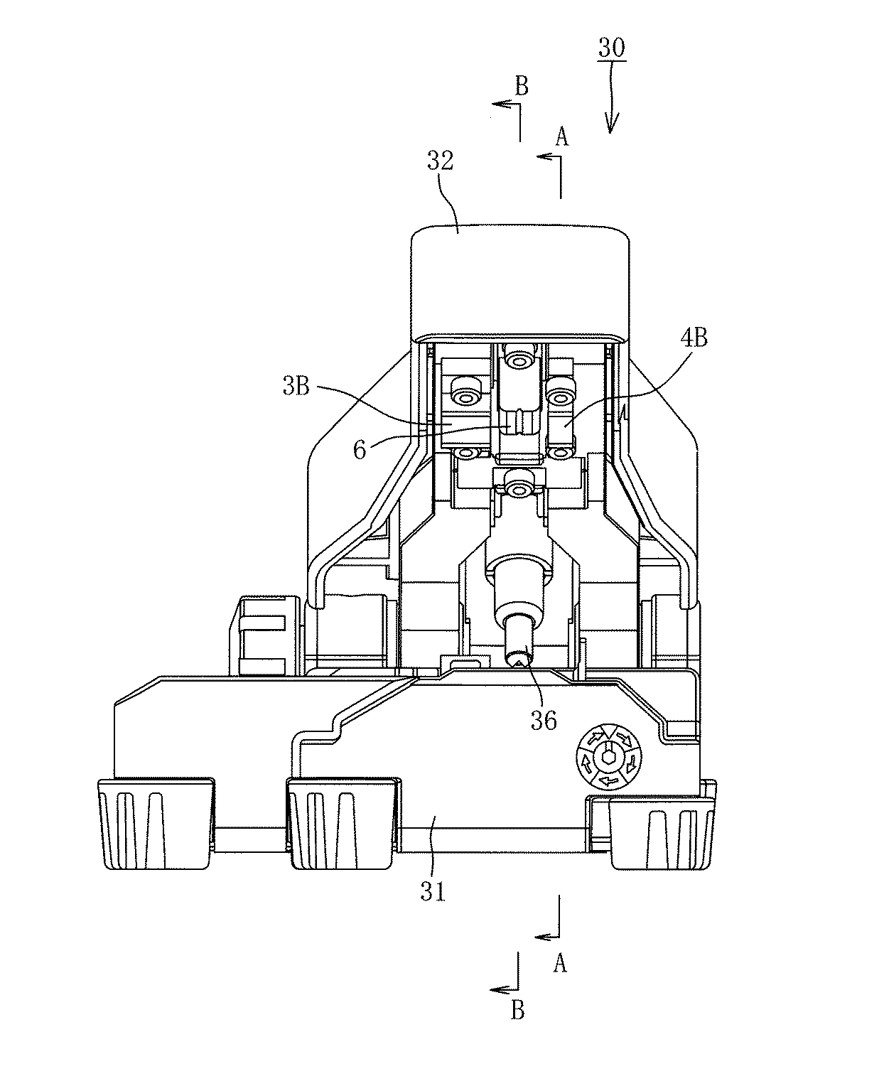
図5は光ファイバ切断装置30の斜視図、図6は図5の光ファイバ切断装置30の正面図、図7及び図8は図5、図6の光ファイバ切断装置30における主として切断機構に関係する部分の構造を概略示すもので、図7は図6のA−A断面図に相当する図、図8は図6のB−B断面図に相当する図である。図7、図8は切断機構の概略説明のためのもので、特に紙面と直交する方向の前後関係の表示などは厳格なものではない。なお、図1〜4における各部に対応する部分には、説明を分かり易くするために、同じ符号を付している。
これらの図において、31は切断装置本体を示す。この切断装置本体31に切断レバー32が回動軸33を中心として回転可能に取り付けられている。切断レバー32は作業をし易くするためのサポートピン36で開いた状態に保つことができる。
切断装置本体31には、切断刃5を取り付けた刃台13が設けられ、刃台13の両側に下クランプ3A、4Aが設けられている。34は光ファイバの被覆部を把持した光ファイバホルダ(光ファイバ保持部2)を装着するホルダ装着部である。
前記切断レバー32側に、前記下クランプ3A、4Aにそれぞれ対応する上クランプ3B、4Bが設けられ、その2つの上クランプ3B、4Bの間に光ファイバ押付部材6が設けられている。35は上クランプ3B、4Bを付勢しているバネを示す。
軸受け部材22は切断装置本体31のベース部25に固定され、軸受け部材22にボルト38で取り付けられた回転軸位置決め用部材24とともに、切断刃5を取り付けた刃台13の両側の回転軸13aを支持している。
回転軸13aは、軸受け部材22側の垂直面S1と、回転軸位置決め用部材24側の傾斜面S2との2つの面に接触した状態で、回転可能に位置決めされている。
軸受け部材22及び回転軸位置決め用部材24はそれぞれ、刃台13の両側の部分を一体に設けている。
刃台13は、軸受け部材22の凹所に配置したバネ26で上方に付勢されている。刃台13の切断刃5と反対側の端部は刃先位置調整用のネジ28で受けられている。ネジ28はベース25にあけた孔40から操作して、先端(上端)位置を変えて刃先位置を調整することができる。
41は下クランプ3A、4Aを固定しているボルト、42は上クランプ3B、4Bを固定しているボルトを示す。
5 is a perspective view of the optical
In these drawings,
The cutting device
On the cutting
The bearing
Each of the bearing
The
上記の光ファイバ切断装置30において、切断レバー32を押し下げて光ファイバ押付け部材6で光ファイバを押し下げた時、上クランプ3B、4Bが下クランプ3A、4Aに向けて下降して、下クランプ3A、4Aに置かれた光ファイバを上下のクランプで把持する。クランプ3、4による光ファイバ把持に僅かに遅れて光ファイバ押付け部材6が光ファイバを押し下げると同時に切断刃5に押し付け、光ファイバに傷が付くと同時に応力破断により切断される。
その際、切断刃5は刃台13とともに回転軸13aを中心として僅かに回転し、その回転により切断刃5は光ファイバを擦るように光ファイバに当たるので、光ファイバに良好な破断面が形成されるような傷を付けることができる。
In the above optical
At that time, the
1 光ファイバ(裸ファイバ)
1A 被覆光ファイバ
2 光ファイバ保持部(光ファイバホルダ)
2a ベース
2b 蓋
3 光ファイバ使用側のクランプ(使用側クランプ)
4 光ファイバ廃棄側のクランプ(廃棄側クランプ)
3A、4A 下クランプ
3B、4B 上クランプ
3c、4c ゴム(クランプ材)
3d 台
5 切断刃
6 光ファイバ押付け部材
6a 凹所
13 刃台
13a 回転軸
22 軸受け部材
24 回転軸位置決め用部材
26 バネ
27 突出部
28 (刃先位置調整用の)ネジ
30 光ファイバ切断装置
1 Optical fiber (bare fiber)
1A Coated
4 Optical fiber discard side clamp (Discard side clamp)
3A,
Claims (5)
少なくとも光ファイバ廃棄側のクランプの材質は弾性体であり、光ファイバ使用側のクランプの把持力が光ファイバ廃棄側のクランプの把持力より大きいことを特徴とする光ファイバ切断装置。 The optical fiber from which the coating is removed extending from the optical fiber coating portion gripped by the optical fiber holding portion is gripped by two fixed clamps on the optical fiber use side and the optical fiber discard side sandwiching the cutting position, respectively. An optical fiber cutting device that applies a tension to an optical fiber by pressing down with an optical fiber pressing member and simultaneously presses the optical fiber against a cutting blade to cut the optical fiber,
An optical fiber cutting device characterized in that at least the material of the clamp on the optical fiber disposal side is an elastic body, and the gripping force of the clamp on the optical fiber use side is larger than the gripping force of the clamp on the optical fiber disposal side.
5. The optical fiber cutting device according to claim 4, wherein the material of the clamp on the optical fiber use side is metal, ceramic, or resin.
Priority Applications (2)
| Application Number | Priority Date | Filing Date | Title |
|---|---|---|---|
| JP2010217632A JP2012073374A (en) | 2010-09-28 | 2010-09-28 | Optical fiber cutting device |
| PCT/JP2011/072210 WO2012043642A1 (en) | 2010-09-28 | 2011-09-28 | Optical fiber cutting apparatus |
Applications Claiming Priority (1)
| Application Number | Priority Date | Filing Date | Title |
|---|---|---|---|
| JP2010217632A JP2012073374A (en) | 2010-09-28 | 2010-09-28 | Optical fiber cutting device |
Publications (1)
| Publication Number | Publication Date |
|---|---|
| JP2012073374A true JP2012073374A (en) | 2012-04-12 |
Family
ID=45893081
Family Applications (1)
| Application Number | Title | Priority Date | Filing Date |
|---|---|---|---|
| JP2010217632A Pending JP2012073374A (en) | 2010-09-28 | 2010-09-28 | Optical fiber cutting device |
Country Status (2)
| Country | Link |
|---|---|
| JP (1) | JP2012073374A (en) |
| WO (1) | WO2012043642A1 (en) |
Cited By (17)
| Publication number | Priority date | Publication date | Assignee | Title |
|---|---|---|---|---|
| JP2014071284A (en) * | 2012-09-28 | 2014-04-21 | Sei Optifrontier Co Ltd | Optical fiber cutter |
| US20140229739A1 (en) | 2013-02-12 | 2014-08-14 | Amazon Technologies, Inc. | Delayed data access |
| EP2902823A1 (en) * | 2014-02-03 | 2015-08-05 | Nyfors Teknologi AB | An optical fiber cleaving device |
| US9590959B2 (en) | 2013-02-12 | 2017-03-07 | Amazon Technologies, Inc. | Data security service |
| US9705674B2 (en) | 2013-02-12 | 2017-07-11 | Amazon Technologies, Inc. | Federated key management |
| US9832171B1 (en) | 2013-06-13 | 2017-11-28 | Amazon Technologies, Inc. | Negotiating a session with a cryptographic domain |
| US9866392B1 (en) | 2014-09-15 | 2018-01-09 | Amazon Technologies, Inc. | Distributed system web of trust provisioning |
| US9942036B2 (en) | 2014-06-27 | 2018-04-10 | Amazon Technologies, Inc. | Supporting a fixed transaction rate with a variably-backed logical cryptographic key |
| US10055594B2 (en) | 2012-06-07 | 2018-08-21 | Amazon Technologies, Inc. | Virtual service provider zones |
| US10075471B2 (en) | 2012-06-07 | 2018-09-11 | Amazon Technologies, Inc. | Data loss prevention techniques |
| US10075295B2 (en) | 2013-02-12 | 2018-09-11 | Amazon Technologies, Inc. | Probabilistic key rotation |
| US10084818B1 (en) | 2012-06-07 | 2018-09-25 | Amazon Technologies, Inc. | Flexibly configurable data modification services |
| US10211977B1 (en) | 2013-02-12 | 2019-02-19 | Amazon Technologies, Inc. | Secure management of information using a security module |
| US10467422B1 (en) | 2013-02-12 | 2019-11-05 | Amazon Technologies, Inc. | Automatic key rotation |
| US10721075B2 (en) | 2014-05-21 | 2020-07-21 | Amazon Technologies, Inc. | Web of trust management in a distributed system |
| US11036869B2 (en) | 2013-02-12 | 2021-06-15 | Amazon Technologies, Inc. | Data security with a security module |
| US20240192445A1 (en) * | 2021-05-13 | 2024-06-13 | Sumitomo Electric Industries, Ltd. | Fusion splice machine |
Family Cites Families (5)
| Publication number | Priority date | Publication date | Assignee | Title |
|---|---|---|---|---|
| JPS614004A (en) * | 1984-06-18 | 1986-01-09 | Nippon Telegr & Teleph Corp <Ntt> | Mechanism and method for cutting optical fiber in one lump |
| JPH02238406A (en) * | 1989-03-11 | 1990-09-20 | Sumitomo Electric Ind Ltd | Method for cutting optical fiber |
| JPH09197137A (en) * | 1996-01-17 | 1997-07-31 | Furukawa Electric Co Ltd:The | Optical fiber cutting method and device |
| JP4256766B2 (en) * | 2003-12-17 | 2009-04-22 | 富士通株式会社 | Optical fiber cutting method and fiber cutter |
| JP2010122555A (en) * | 2008-11-21 | 2010-06-03 | Fujikura Ltd | Optical fiber-cutting apparatus |
-
2010
- 2010-09-28 JP JP2010217632A patent/JP2012073374A/en active Pending
-
2011
- 2011-09-28 WO PCT/JP2011/072210 patent/WO2012043642A1/en not_active Ceased
Cited By (36)
| Publication number | Priority date | Publication date | Assignee | Title |
|---|---|---|---|---|
| US10055594B2 (en) | 2012-06-07 | 2018-08-21 | Amazon Technologies, Inc. | Virtual service provider zones |
| US10834139B2 (en) | 2012-06-07 | 2020-11-10 | Amazon Technologies, Inc. | Flexibly configurable data modification services |
| US10474829B2 (en) | 2012-06-07 | 2019-11-12 | Amazon Technologies, Inc. | Virtual service provider zones |
| US10084818B1 (en) | 2012-06-07 | 2018-09-25 | Amazon Technologies, Inc. | Flexibly configurable data modification services |
| US10075471B2 (en) | 2012-06-07 | 2018-09-11 | Amazon Technologies, Inc. | Data loss prevention techniques |
| JP2014071284A (en) * | 2012-09-28 | 2014-04-21 | Sei Optifrontier Co Ltd | Optical fiber cutter |
| US10467422B1 (en) | 2013-02-12 | 2019-11-05 | Amazon Technologies, Inc. | Automatic key rotation |
| US10666436B2 (en) | 2013-02-12 | 2020-05-26 | Amazon Technologies, Inc. | Federated key management |
| US12432054B2 (en) | 2013-02-12 | 2025-09-30 | Amazon Technologies, Inc. | Federated key management |
| US11695555B2 (en) | 2013-02-12 | 2023-07-04 | Amazon Technologies, Inc. | Federated key management |
| US10075295B2 (en) | 2013-02-12 | 2018-09-11 | Amazon Technologies, Inc. | Probabilistic key rotation |
| US9705674B2 (en) | 2013-02-12 | 2017-07-11 | Amazon Technologies, Inc. | Federated key management |
| US10211977B1 (en) | 2013-02-12 | 2019-02-19 | Amazon Technologies, Inc. | Secure management of information using a security module |
| US10210341B2 (en) | 2013-02-12 | 2019-02-19 | Amazon Technologies, Inc. | Delayed data access |
| US11372993B2 (en) | 2013-02-12 | 2022-06-28 | Amazon Technologies, Inc. | Automatic key rotation |
| US11036869B2 (en) | 2013-02-12 | 2021-06-15 | Amazon Technologies, Inc. | Data security with a security module |
| US10382200B2 (en) | 2013-02-12 | 2019-08-13 | Amazon Technologies, Inc. | Probabilistic key rotation |
| US10404670B2 (en) | 2013-02-12 | 2019-09-03 | Amazon Technologies, Inc. | Data security service |
| US9590959B2 (en) | 2013-02-12 | 2017-03-07 | Amazon Technologies, Inc. | Data security service |
| US20140229739A1 (en) | 2013-02-12 | 2014-08-14 | Amazon Technologies, Inc. | Delayed data access |
| US10601789B2 (en) | 2013-06-13 | 2020-03-24 | Amazon Technologies, Inc. | Session negotiations |
| US9832171B1 (en) | 2013-06-13 | 2017-11-28 | Amazon Technologies, Inc. | Negotiating a session with a cryptographic domain |
| US12395472B1 (en) | 2013-06-13 | 2025-08-19 | Amazon Technologies, Inc. | Key rotation techniques |
| US10313312B2 (en) | 2013-06-13 | 2019-06-04 | Amazon Technologies, Inc. | Key rotation techniques |
| US11470054B2 (en) | 2013-06-13 | 2022-10-11 | Amazon Technologies, Inc. | Key rotation techniques |
| US11323479B2 (en) | 2013-07-01 | 2022-05-03 | Amazon Technologies, Inc. | Data loss prevention techniques |
| US12107897B1 (en) | 2013-07-01 | 2024-10-01 | Amazon Technologies, Inc. | Data loss prevention techniques |
| EP2902823A1 (en) * | 2014-02-03 | 2015-08-05 | Nyfors Teknologi AB | An optical fiber cleaving device |
| US10215922B2 (en) | 2014-02-03 | 2019-02-26 | Nyfors Teknologi Ab | Optical fiber cleaving device |
| US10721075B2 (en) | 2014-05-21 | 2020-07-21 | Amazon Technologies, Inc. | Web of trust management in a distributed system |
| US11368300B2 (en) | 2014-06-27 | 2022-06-21 | Amazon Technologies, Inc. | Supporting a fixed transaction rate with a variably-backed logical cryptographic key |
| US9942036B2 (en) | 2014-06-27 | 2018-04-10 | Amazon Technologies, Inc. | Supporting a fixed transaction rate with a variably-backed logical cryptographic key |
| US10587405B2 (en) | 2014-06-27 | 2020-03-10 | Amazon Technologies, Inc. | Supporting a fixed transaction rate with a variably-backed logical cryptographic key |
| US11626996B2 (en) | 2014-09-15 | 2023-04-11 | Amazon Technologies, Inc. | Distributed system web of trust provisioning |
| US9866392B1 (en) | 2014-09-15 | 2018-01-09 | Amazon Technologies, Inc. | Distributed system web of trust provisioning |
| US20240192445A1 (en) * | 2021-05-13 | 2024-06-13 | Sumitomo Electric Industries, Ltd. | Fusion splice machine |
Also Published As
| Publication number | Publication date |
|---|---|
| WO2012043642A1 (en) | 2012-04-05 |
Similar Documents
| Publication | Publication Date | Title |
|---|---|---|
| JP2012073374A (en) | Optical fiber cutting device | |
| CN103329015B (en) | The coating minimizing technology of coated fiber and the coating removal device of coated fiber | |
| CN101231366B (en) | Optical fiber cutting device | |
| US20100187276A1 (en) | Optical fiber cutting device, optical fiber cutting method, and optical fiber cutting blade member | |
| JP5403758B2 (en) | Waste recovery equipment for optical fiber cutting equipment | |
| HU226438B1 (en) | Improvements to ceramic cutters | |
| KR20120054641A (en) | Bladeless optical fiber cleaver | |
| CN101523254A (en) | Optical fiber cutting apparatus and optical fiber cutting method | |
| JP5102581B2 (en) | Cutting blade holder moving mechanism in optical fiber cutting device, optical fiber cutting device, and optical fiber cutting method | |
| JP2012226252A (en) | Optical fiber cutting tool and optical fiber cutting method | |
| JP5768312B2 (en) | Coating remover | |
| US20100127034A1 (en) | Optical Fiber Cleave Tool | |
| JP2001296430A (en) | Optical fiber cutter | |
| JP4057553B2 (en) | Optical fiber cutter | |
| JP5117437B2 (en) | Fiber optic cutting machine | |
| JP3605754B2 (en) | Optical fiber cutter | |
| JP4737025B2 (en) | Optical fiber cutting device and optical fiber cutting method | |
| US12253717B2 (en) | Fiber cutter and fiber cutting method | |
| JP4150990B2 (en) | Optical fiber cutter | |
| JPS6034296A (en) | How to cut a blade used in an image forming device | |
| JP6698582B2 (en) | Optical fiber cutter | |
| JP2002286944A (en) | Handy type optical fiber cutter | |
| JP6159913B1 (en) | Scissors | |
| JP2005096004A (en) | Optical fiber cutter and optical fiber cutting method using the same | |
| JP5856586B2 (en) | Cutting tool |