JP2012050840A - Medical closure clip system - Google Patents
Medical closure clip system Download PDFInfo
- Publication number
- JP2012050840A JP2012050840A JP2011230116A JP2011230116A JP2012050840A JP 2012050840 A JP2012050840 A JP 2012050840A JP 2011230116 A JP2011230116 A JP 2011230116A JP 2011230116 A JP2011230116 A JP 2011230116A JP 2012050840 A JP2012050840 A JP 2012050840A
- Authority
- JP
- Japan
- Prior art keywords
- screen
- clip
- tissue
- clip system
- clips
- Prior art date
- Legal status (The legal status is an assumption and is not a legal conclusion. Google has not performed a legal analysis and makes no representation as to the accuracy of the status listed.)
- Pending
Links
- 239000012530 fluid Substances 0.000 claims abstract description 51
- 239000000835 fiber Substances 0.000 claims abstract description 32
- 238000012546 transfer Methods 0.000 claims description 25
- 238000004299 exfoliation Methods 0.000 claims description 21
- 230000002093 peripheral effect Effects 0.000 claims description 18
- 239000000463 material Substances 0.000 claims description 16
- 230000008878 coupling Effects 0.000 claims description 9
- 238000010168 coupling process Methods 0.000 claims description 9
- 238000005859 coupling reaction Methods 0.000 claims description 9
- 239000000853 adhesive Substances 0.000 claims description 6
- 230000001070 adhesive effect Effects 0.000 claims description 6
- 239000006261 foam material Substances 0.000 claims description 5
- 238000005452 bending Methods 0.000 claims 1
- 239000013305 flexible fiber Substances 0.000 claims 1
- 230000002209 hydrophobic effect Effects 0.000 claims 1
- 238000000034 method Methods 0.000 abstract description 62
- 230000002262 irrigation Effects 0.000 abstract description 11
- 238000003973 irrigation Methods 0.000 abstract description 11
- 125000006850 spacer group Chemical group 0.000 abstract description 8
- 238000000926 separation method Methods 0.000 abstract 2
- 210000001519 tissue Anatomy 0.000 description 124
- 210000003491 skin Anatomy 0.000 description 29
- 206010052428 Wound Diseases 0.000 description 27
- 208000027418 Wounds and injury Diseases 0.000 description 27
- 238000013459 approach Methods 0.000 description 15
- 238000001356 surgical procedure Methods 0.000 description 15
- 238000002679 ablation Methods 0.000 description 11
- 239000006260 foam Substances 0.000 description 9
- 238000007920 subcutaneous administration Methods 0.000 description 8
- 230000032798 delamination Effects 0.000 description 6
- 230000003187 abdominal effect Effects 0.000 description 5
- 230000002745 absorbent Effects 0.000 description 5
- 239000002250 absorbent Substances 0.000 description 5
- 208000015181 infectious disease Diseases 0.000 description 5
- 210000003205 muscle Anatomy 0.000 description 5
- 238000005538 encapsulation Methods 0.000 description 4
- 210000003195 fascia Anatomy 0.000 description 4
- 238000009581 negative-pressure wound therapy Methods 0.000 description 4
- 206010040102 Seroma Diseases 0.000 description 3
- 210000000683 abdominal cavity Anatomy 0.000 description 3
- 238000000429 assembly Methods 0.000 description 3
- 230000007547 defect Effects 0.000 description 3
- 230000000694 effects Effects 0.000 description 3
- 238000009434 installation Methods 0.000 description 3
- 210000004379 membrane Anatomy 0.000 description 3
- 239000012528 membrane Substances 0.000 description 3
- 230000008439 repair process Effects 0.000 description 3
- 206010018852 Haematoma Diseases 0.000 description 2
- 208000032843 Hemorrhage Diseases 0.000 description 2
- 206010019909 Hernia Diseases 0.000 description 2
- 230000009471 action Effects 0.000 description 2
- 239000002390 adhesive tape Substances 0.000 description 2
- 230000000712 assembly Effects 0.000 description 2
- 230000000740 bleeding effect Effects 0.000 description 2
- 210000000988 bone and bone Anatomy 0.000 description 2
- 238000010276 construction Methods 0.000 description 2
- 208000014674 injury Diseases 0.000 description 2
- 238000002844 melting Methods 0.000 description 2
- 230000008018 melting Effects 0.000 description 2
- 210000000056 organ Anatomy 0.000 description 2
- 230000000149 penetrating effect Effects 0.000 description 2
- 230000002980 postoperative effect Effects 0.000 description 2
- 238000003825 pressing Methods 0.000 description 2
- 230000009467 reduction Effects 0.000 description 2
- 231100000241 scar Toxicity 0.000 description 2
- -1 silk Polymers 0.000 description 2
- 230000008733 trauma Effects 0.000 description 2
- VPVXHAANQNHFSF-UHFFFAOYSA-N 1,4-dioxan-2-one Chemical compound O=C1COCCO1 VPVXHAANQNHFSF-UHFFFAOYSA-N 0.000 description 1
- SJDLIJNQXLJBBE-UHFFFAOYSA-N 1,4-dioxepan-2-one Chemical compound O=C1COCCCO1 SJDLIJNQXLJBBE-UHFFFAOYSA-N 0.000 description 1
- AOLNDUQWRUPYGE-UHFFFAOYSA-N 1,4-dioxepan-5-one Chemical compound O=C1CCOCCO1 AOLNDUQWRUPYGE-UHFFFAOYSA-N 0.000 description 1
- LCSKNASZPVZHEG-UHFFFAOYSA-N 3,6-dimethyl-1,4-dioxane-2,5-dione;1,4-dioxane-2,5-dione Chemical group O=C1COC(=O)CO1.CC1OC(=O)C(C)OC1=O LCSKNASZPVZHEG-UHFFFAOYSA-N 0.000 description 1
- PHOJOSOUIAQEDH-UHFFFAOYSA-N 5-hydroxypentanoic acid Chemical compound OCCCCC(O)=O PHOJOSOUIAQEDH-UHFFFAOYSA-N 0.000 description 1
- FXXZYZRHXUPAIE-UHFFFAOYSA-N 6,6-dimethyl-1,4-dioxan-2-one Chemical compound CC1(C)COCC(=O)O1 FXXZYZRHXUPAIE-UHFFFAOYSA-N 0.000 description 1
- JSMRMEYFZHIPJV-UHFFFAOYSA-N C1C2CCC1C2 Chemical compound C1C2CCC1C2 JSMRMEYFZHIPJV-UHFFFAOYSA-N 0.000 description 1
- GDOPTJXRTPNYNR-UHFFFAOYSA-N CC1CCCC1 Chemical compound CC1CCCC1 GDOPTJXRTPNYNR-UHFFFAOYSA-N 0.000 description 1
- 244000025254 Cannabis sativa Species 0.000 description 1
- 235000012766 Cannabis sativa ssp. sativa var. sativa Nutrition 0.000 description 1
- 235000012765 Cannabis sativa ssp. sativa var. spontanea Nutrition 0.000 description 1
- 229920000742 Cotton Polymers 0.000 description 1
- 208000002197 Ehlers-Danlos syndrome Diseases 0.000 description 1
- 229920001410 Microfiber Polymers 0.000 description 1
- 208000008589 Obesity Diseases 0.000 description 1
- 239000004952 Polyamide Substances 0.000 description 1
- 239000004698 Polyethylene Substances 0.000 description 1
- 229920006328 Styrofoam Polymers 0.000 description 1
- 208000002847 Surgical Wound Diseases 0.000 description 1
- 206010042674 Swelling Diseases 0.000 description 1
- 210000001015 abdomen Anatomy 0.000 description 1
- 238000012084 abdominal surgery Methods 0.000 description 1
- 230000001154 acute effect Effects 0.000 description 1
- 210000000577 adipose tissue Anatomy 0.000 description 1
- 229920003232 aliphatic polyester Polymers 0.000 description 1
- 230000015572 biosynthetic process Effects 0.000 description 1
- 208000034158 bleeding Diseases 0.000 description 1
- 210000001124 body fluid Anatomy 0.000 description 1
- 235000009120 camo Nutrition 0.000 description 1
- 238000005266 casting Methods 0.000 description 1
- 235000005607 chanvre indien Nutrition 0.000 description 1
- 238000004891 communication Methods 0.000 description 1
- 229920001577 copolymer Polymers 0.000 description 1
- 210000004207 dermis Anatomy 0.000 description 1
- 230000008030 elimination Effects 0.000 description 1
- 238000003379 elimination reaction Methods 0.000 description 1
- 210000005081 epithelial layer Anatomy 0.000 description 1
- 150000002148 esters Chemical class 0.000 description 1
- 210000000416 exudates and transudate Anatomy 0.000 description 1
- 229920002313 fluoropolymer Polymers 0.000 description 1
- 239000004811 fluoropolymer Substances 0.000 description 1
- 239000003292 glue Substances 0.000 description 1
- 239000003102 growth factor Substances 0.000 description 1
- 230000035876 healing Effects 0.000 description 1
- 239000011487 hemp Substances 0.000 description 1
- 229920001519 homopolymer Polymers 0.000 description 1
- 238000010348 incorporation Methods 0.000 description 1
- 210000001503 joint Anatomy 0.000 description 1
- 238000009940 knitting Methods 0.000 description 1
- JJTUDXZGHPGLLC-UHFFFAOYSA-N lactide Chemical compound CC1OC(=O)C(C)OC1=O JJTUDXZGHPGLLC-UHFFFAOYSA-N 0.000 description 1
- 239000007788 liquid Substances 0.000 description 1
- 230000014759 maintenance of location Effects 0.000 description 1
- 239000002184 metal Substances 0.000 description 1
- 239000003658 microfiber Substances 0.000 description 1
- 238000002324 minimally invasive surgery Methods 0.000 description 1
- 235000020824 obesity Nutrition 0.000 description 1
- 230000035515 penetration Effects 0.000 description 1
- 229920002463 poly(p-dioxanone) polymer Polymers 0.000 description 1
- 229920002647 polyamide Polymers 0.000 description 1
- 239000000622 polydioxanone Substances 0.000 description 1
- 229920000728 polyester Polymers 0.000 description 1
- 229920000573 polyethylene Polymers 0.000 description 1
- 229920002959 polymer blend Polymers 0.000 description 1
- 229920000098 polyolefin Polymers 0.000 description 1
- 229920002635 polyurethane Polymers 0.000 description 1
- 239000004814 polyurethane Substances 0.000 description 1
- 239000011118 polyvinyl acetate Substances 0.000 description 1
- 239000011148 porous material Substances 0.000 description 1
- 230000008569 process Effects 0.000 description 1
- 239000000047 product Substances 0.000 description 1
- 238000005086 pumping Methods 0.000 description 1
- 238000011084 recovery Methods 0.000 description 1
- 238000002271 resection Methods 0.000 description 1
- 230000037390 scarring Effects 0.000 description 1
- 239000008261 styrofoam Substances 0.000 description 1
- 210000004304 subcutaneous tissue Anatomy 0.000 description 1
- 239000013589 supplement Substances 0.000 description 1
- 239000003356 suture material Substances 0.000 description 1
- 230000008961 swelling Effects 0.000 description 1
- YFHICDDUDORKJB-UHFFFAOYSA-N trimethylene carbonate Chemical compound O=C1OCCCO1 YFHICDDUDORKJB-UHFFFAOYSA-N 0.000 description 1
- PAPBSGBWRJIAAV-UHFFFAOYSA-N ε-Caprolactone Chemical compound O=C1CCCCCO1 PAPBSGBWRJIAAV-UHFFFAOYSA-N 0.000 description 1
Images


Landscapes
- Surgical Instruments (AREA)
Abstract
Description
本発明は、概して、医療用閉塞及び傷浸出液取り扱い器具に関し、特に、スクリーン閉塞部材の取り付けシステム及び方法、及び切開及び傷といった組織剥離を閉塞するための器具に関しており、このような閉塞部材及び器具は任意に生体吸収性材料である。 The present invention relates generally to medical occlusion and wound exudate handling instruments, and more particularly to a system and method for attaching a screen occlusion member, and an instrument for occluding tissue detachment such as incisions and wounds. Is optionally a bioabsorbable material.
歯科を含めて広く定義される医療の分野では、皮膚の切開が通常外科手術で行われ、下層の組織、臓器、関節、骨格構造等に手を伸ばす。切開及び閉塞技術は、一般に、外科手術で重要な部分である。それらは、外科チーム及び多くの外科手術の重要な部分に関する他の資源を占める傾向にある。 In the medical field that is widely defined including dentistry, skin incision is usually performed by surgery, reaching to the underlying tissues, organs, joints, skeletal structures and the like. Incision and occlusion techniques are generally an important part of surgery. They tend to occupy the surgical team and other resources related to an important part of many surgical procedures.
外科医は、一般に、切開を最小限にすることによって、及び術後の腫れ、出血、血清腫、感染、及び他の望ましくない術後の副次的な悪影響を減らし易くする様々な閉塞技術を採用することによって、患者に対して外科手術による外傷及び瘢痕を最小限にするよう努力する。例えば、内視鏡が補助する外科手術、顕微鏡外科手術、及びコンピュータで強化した器具類(例えば、Intuitive Surgical,Inc.of Sunnyvale, Calif.から入手可能なthe DaVinci System)が、一般に、低侵襲的(「MIS」)な手術及び方法であると考えられており、ますます好評であることが分かっている。このような評判は、少なくとも一部には、このような方法によって最小限の大きさの傷跡しか残らないことによるものだけではなく、筋膜及び筋肉層に対する最小限の外傷及びこれに応じた速い回復を可能にすることによるものである。しかしながら、外科医は、このような配慮と、様々な外科手術を行うように十分に手を伸ばすことをバランスさせなければならない。典型的な外科手術は、切断又は切開段階及び閉塞段階を含んでいる。近年、外科的な切断、切開及び形成に関して、顕著に進歩している。外科的な閉塞方法は、縫合糸、クリップ、ステープル及び接着用テープを含んでいる。しかしながら、縫合は時間がかかって面倒である可能性がある。さらに、結合した組織構造は、他の閉塞方法の影響を受け易い。MISは、多くの場合、剥離した組織構造へのアクセスを制限するため、組織構造を接近させて閉塞するのをより難しくする。 Surgeons generally employ a variety of occlusion techniques that help minimize incisions and reduce postoperative swelling, bleeding, seromas, infections, and other undesirable postoperative side effects. By trying to minimize surgical trauma and scarring on the patient. For example, endoscopic-assisted surgery, microscopic surgery, and computer-enhanced instruments (eg, the DaVinci System available from Intuitive Surgical, Inc. of Sunnyvale, Calif.) Are generally less invasive. ("MIS") surgery and methods are considered and are becoming increasingly popular. Such a reputation is not only due, at least in part, to leaving a minimally sized scar by such a method, but also minimal trauma to the fascia and muscle layers and correspondingly fast. This is by enabling recovery. However, the surgeon must balance such consideration with reaching sufficiently to perform various surgical procedures. A typical surgical procedure includes a cutting or incision stage and an occlusion stage. In recent years, significant progress has been made regarding surgical cutting, incision and formation. Surgical closure methods include sutures, clips, staples and adhesive tape. However, suturing can be time consuming and cumbersome. Furthermore, the combined tissue structure is susceptible to other occlusive methods. MIS often makes it more difficult to close and close the tissue structure to limit access to the detached tissue structure.
MISと対照的に、いくつかの外科手術は、その性質からして長い切開を必要とする。例として、「持ち上げ」及び縮小処置、欠陥の閉塞のための組織片処置、及び多くの肥満治療処理といった、皮膚の切除手術を含む。このような広範囲に及ぶ欠陥の縫合は、時間がかかって面倒である可能性がある。 In contrast to MIS, some surgical procedures require long incisions due to their nature. Examples include skin resection surgery such as “lifting” and reduction procedures, tissue strip procedures for defect occlusion, and many obesity treatment procedures. Such extensive defect stitching can be time consuming and cumbersome.
外科手術における「第1の目的」(治療の主要な目的)は、切開を「閉塞する」ことである。骨、筋膜及び筋肉といった負荷に耐える組織では、縫合材料、ステープル、又はプレート及びネジとして、これはかなりの量の材料を要する。「閉塞」すべき傷では、上皮層を密閉しなければならない。これを実現するために、皮膚及び皮下層(すなわち、それぞれ深い皮膚の弾性層及び浅筋膜又は脂肪組織の線維層)の「負荷に耐える」領域を、少なくとも接近するよう保持しなければならない。重要な検討材料は、感染対策及び出血の管理、傷跡の減少、血腫、血清腫、及び「死腔(デッドスペース)」の形成の可能性の除去、を含んでいる。死腔の問題は、皮下の閉塞で生じる傾向がある。比較的浅い切開は、通常、縫合糸、ステープル、糊、及び接着テープ片といった、表面に適用する閉塞方法で閉塞可能である。しかしながら深い切開は、皮膚表面の閉塞だけではなく、負荷に耐える面での筋肉層の縫合糸の時間がかかる配置をも要する。吸収性縫合糸は、通常このような目的のために使用し、外科縫合の重要なクラスを具えている。様々な要因に応じて、吸収性縫合糸は、一般に、数日間から数ヶ月にわたって分解する。市販の例として、poliglecaprone及びPDS.RTM.(polydrioxanone)及びVicryl.RTM.(polyglactin)縫合糸を具える、Monocryl.RTM.モノフィラメントの吸収性の合成縫合糸を有しており、全てがEthicon,Inc.,of Somerville,N.Jから入手可能である。 The “first goal” in surgery (the primary goal of treatment) is to “close” the incision. In tissues that can withstand loads such as bone, fascia and muscle, this requires a significant amount of material as suture material, staples, or plates and screws. In wounds to be “occluded”, the epithelial layer must be sealed. To achieve this, the “load-bearing” regions of the skin and subcutaneous layers (ie, deep skin elastic layer and superficial fascia or adipose tissue fiber layer, respectively) must be kept at least in close proximity. Important considerations include infection control and bleeding management, scar reduction, hematoma, seroma, and elimination of the possibility of forming “dead spaces”. Dead space problems tend to occur with subcutaneous obstruction. A relatively shallow incision can usually be occluded with occlusion methods applied to the surface, such as sutures, staples, glue, and pieces of adhesive tape. However, a deep incision requires not only a skin surface occlusion, but also a time consuming arrangement of muscle layer sutures on the surface to withstand the load. Absorbable sutures are usually used for such purposes and comprise an important class of surgical sutures. Depending on various factors, absorbable sutures typically degrade over days to months. Commercial examples include polycaprone and PDS. RTM. (Polydioxanone) and Vicryl. RTM. (Polyglactin) with a suture, Monocryl. RTM. Monofilament absorbable synthetic sutures, all from Ethicon, Inc. , Of Somerville, N .; Available from J.
外科的なメッシュが通常、負荷に耐える面又は欠陥をその中で架橋又は強化するよう使用される。縫合糸又は締結具で結合する場合、外科的なメッシュが外科的閉塞器具の別の重要なクラスを代表する。応用例が、再構成、ヘルニアの修復、及び臓器の修復を有している。このような処置では、外科的メッシュ繊維のプロテーゼが切開手術又は内視鏡(MIS)処置のいずれかを介して患者の中に挿入される。ヘルニアの修復のための編まれた外科的メッシュがAgarwalらによるEthicon,Inc.の米国特許番号第6,287,316号に開示されている。Duncanによる米国特許番号第4,548,202号の別のEthicon,Inc.の特許が、組織の部分に通すために間隔を空けた脚を具えた様々な締結部材を含むメッシュ組織締結具を開示している。別の閉塞処置は、皮膚の端部又は骨を通したピン又は棒の配置の後に傷を架橋する外部の留め具又は固定器具を配置し、さらに高い頻度で、長期間にわたって締め付けて閉塞、安定化又は伸延をもたらすことが可能なウオームネジの器具を組み込むことを含んでいる。 Surgical meshes are usually used to bridge or strengthen surfaces or defects that can withstand loads. Surgical meshes represent another important class of surgical occlusion devices when joined with sutures or fasteners. Applications include reconstruction, hernia repair, and organ repair. In such procedures, a surgical mesh fiber prosthesis is inserted into the patient via either an open surgery or endoscopic (MIS) procedure. A knitted surgical mesh for hernia repair is described by Agarwal et al. Ethicon, Inc. U.S. Pat. No. 6,287,316. Another Ethicon, Inc., U.S. Pat. No. 4,548,202 to Duncan. Discloses a mesh tissue fastener that includes various fastening members with spaced legs for passing through a portion of tissue. Another occlusion procedure is to place an external fastener or fixation device that bridges the wound after placement of a pin or rod through the end of the skin or bone and, more frequently, tightens and stabilizes over long periods of time. Including the incorporation of a worm screw instrument capable of providing angulation or distraction.
流体の取り扱いは、観血手術及び低侵襲手術双方のもう一つの重要な態様を表している。手術後の流体の排出は、体液を収集及び排出するよう構成された、チューブ、スポンジ、及び多孔質材料の様々な組み合わせで行うことができる。従来技術は、排出を補助するたえの技術及び方法を有している。例えば、Zamierowskiによる米国特許番号第4,969,880号;米国特許番号第5,100,396号;米国特許番号第5,261,893号;米国特許番号第5,527,293号;及び米国特許番号第6,071,267号が、圧力差、すなわち、真空及び正圧の使用して外科的切開部位を含む傷から流体の排出を補助することを開示している。このような圧力差は、傷の内部又は外部に多孔質の発泡材料を適用して、透過性、半透過性、又は不透過性膜で傷を覆い、傷に吸引真空源を接続することによって生じさせることが可能である。患者から引き出される流体は、処分のために収集される。このような流体の制御方法は、患者の治療において顕著な改善を実現することを示している。術後及びそれ以外における流体の取り扱いの別の態様が、潅注、感染対策、疼痛管理、成長因子の適用等を目的とした傷の部位への流体の適用に関する。また、傷の排出器具を使用して組織の固定及び不動を実現することで、治療及び閉塞を補助する。これは、閉塞した傷の内部の排出及び外部の真空装置の双方によって実現可能である。また、ボーラス投与するよう覆う被覆材(dressings)(ステント被覆材)、テープの貼り付け、絆創膏の貼り付け及び(接触)キャスティング(casting)によって、組織の固定を同様に実現できる。 Fluid handling represents another important aspect of both open surgery and minimally invasive surgery. Post-surgery fluid drainage can be performed with various combinations of tubes, sponges, and porous materials configured to collect and drain bodily fluids. The prior art has techniques and methods for assisting discharge. For example, US Pat. No. 4,969,880 by Zamierowski; US Pat. No. 5,100,396; US Pat. No. 5,261,893; US Pat. No. 5,527,293; and US U.S. Patent No. 6,071,267 discloses the use of pressure differentials, i.e., vacuum and positive pressure, to assist in draining fluid from a wound including a surgical incision site. Such pressure differences can be achieved by applying a porous foam material inside or outside the wound, covering the wound with a permeable, semi-permeable, or impermeable membrane and connecting a vacuum source to the wound. Can be generated. Fluid drawn from the patient is collected for disposal. Such fluid control methods have been shown to achieve significant improvements in patient treatment. Another aspect of fluid handling after surgery and elsewhere relates to the application of fluid to the wound site for purposes of irrigation, infection control, pain management, growth factor application, and the like. Also, treatment and occlusion are aided by using tissue removal devices to achieve tissue fixation and immobilization. This can be achieved by both internal discharge of the closed wound and an external vacuum device. Also, tissue fixation can be achieved in the same manner by coverings (stent coverings) to be administered as a bolus, applying a tape, applying an adhesive bandage, and (contacting) casting.
従来、本発明と負圧創傷治療(「NPWT」)との組合わせを含む、本発明の利点及び態様を具えた利用可能な医療用閉塞スクリーンアッセンブリは無い。 Conventionally, there are no available medical occlusion screen assemblies that include the advantages and aspects of the present invention, including a combination of the present invention and negative pressure wound therapy ("NPWT").
本発明に係る一形態の実施では、医療用閉塞スクリーン器具が提供されており、この器具はチューブ状の縦型のライザーと、ライザーの間を延びる返しを具えた繊維と、横方向のスペーサとを具えた網状のスクリーンを有している。一体型又は別体の縫合糸を設けることができる。任意の周縁部材が、スクリーン部材を部分的に取り囲んでおり、縦型のライザーと流体結合されてチューブアッセンブリを形成する周縁のチューブを具えることができる。チューブアッセンブリは、縦型のライザーと共働して、排出管の方法で組織の剥離から流体を排出し、潅注の方法でチューブアッセンブリの中に流体を導入する。本発明の係る一実施例では、チューブアッセンブリが排出し易くするよう真空源に流体接続されている。本発明の別の実施例では、周縁チューブが周囲の組織を通り抜けて所定の位置にスクリーン部材を固定する。スポンジといった流体移送部材が、スクリーンの延長部の近く又は延長部の上に任意に配置されており、例えば、真空又はポンプ源とともに流体を移送する。本発明の別の実施例が、スクリーンに取り付けられ組織の剥離にスクリーンを固定するよう構成された縫合糸を有している。また、代替的な実施例の縦型のライザーが開示されており、患者の体を動力として用いて活発な流体の移送を提供できる。本発明のさらに別の代替的な実施例は、剥離を閉塞するため剥離の中での機械的な固定用のスクリーンの返しを使用する。閉塞スクリーン、チューブ、縫合糸、流体移送部材及び傾度力源の様々な組み合わせを用いた剥離の閉塞、潅注及び排出方法が開示されている。本発明に係る閉塞スクリーンは、スクリーン及び返しを具えたストランドに関する機械的又は他の力を使用して、剥離した組織を固定し、血腫及び血清腫の影響を形成する可能性のある皮下の空洞又は嚢状腔の変形を除去又は減らす。 In one form of implementation according to the present invention, a medical occlusion screen device is provided, the device comprising a tubular vertical riser, fibers with barbs extending between the risers, and lateral spacers. It has a mesh-like screen. An integral or separate suture can be provided. An optional peripheral member may partially surround the screen member and may comprise a peripheral tube that is fluidly coupled to the vertical riser to form a tube assembly. The tube assembly cooperates with the vertical riser to drain fluid from tissue ablation in a drain tube manner and introduce fluid into the tube assembly in a irrigation manner. In one embodiment of the present invention, the tube assembly is fluidly connected to a vacuum source to facilitate drainage. In another embodiment of the present invention, the peripheral tube passes through the surrounding tissue and secures the screen member in place. A fluid transfer member, such as a sponge, is optionally placed near or on the extension of the screen to transfer the fluid with, for example, a vacuum or pump source. Another embodiment of the invention includes a suture that is attached to the screen and configured to secure the screen to tissue detachment. An alternative embodiment of a vertical riser is also disclosed, which can provide active fluid transfer using the patient's body as power. Yet another alternative embodiment of the present invention uses the return of a mechanical locking screen during the peel to close the peel. Disclosed occlusion, irrigation and drainage methods using various combinations of occlusion screens, tubes, sutures, fluid transfer members and gradient force sources are disclosed. The occlusion screen according to the present invention uses a mechanical or other force on the screen and the strands with barbs to fix the exfoliated tissue and form the effect of hematoma and seroma. Or remove or reduce the deformation of the sac cavity.
1.序論及び環境
必要に応じて、本発明の詳細な実施例が本書で開示されている;しかしながら、開示された実施例は、単に本発明の一例であり、様々な形式で実施してもよいことに留意されたい。このため、本書で開示された特定の構造及び機能的な詳細は、限定的なものであると解釈すべきではなく、単に特許請求の範囲の原則とし、実質的に適切な詳細な構成で本発明を様々に使用するよう当業者に示唆するための典型的な原則として解釈すべきである。
1. Introduction and Environment Where appropriate, detailed embodiments of the present invention are disclosed herein; however, the disclosed embodiments are merely examples of the present invention and may be implemented in various forms. Please note that. For this reason, the specific structural and functional details disclosed in this document should not be construed as limiting, but merely as the principles of the claims. It should be construed as a typical principle to suggest one of ordinary skill in the art to make various use of the invention.
便宜上以下の詳細において特定の用語を使用することとし、限定はしない。例えば、「上方に」、「下方に」、「右方に」及び「左方に」という単語は、言及される図面における方向に言及する。「内側に」及び「外側に」という単語は、それぞれ、近づいて及び離れる向きに言及するものであり、幾何学的な中心はその説明及び図示されている部分である。「横方向に」及び「鉛直に」という単語は、一般に、左右に及び上下にということをそれぞれ意味する。これらの用語は、特別に言及する単語、その派生語、及び同じような意味の単語を含む。 For convenience, certain terms will be used in the following details, without limitation. For example, the words “upwardly”, “downwardly”, “to the right” and “to the left” refer to the direction in the referenced drawing. The words “inside” and “outside” refer to the approaching and leaving directions, respectively, and the geometric center is the part of the description and illustrated. The words “laterally” and “vertically” generally mean left and right and up and down, respectively. These terms include words specifically mentioned, derivatives thereof, and words of similar meaning.
詳細に図面を参照すると、符号2は概して、本発明を実施する医療用閉塞スクリーン器具又はシステムを示す。閉塞スクリーンシステム2の有用な適用の一般性について限定はせず、本書で開示された主要な用途は、傷又は切開4といった、第1及び第2の組織部分の剥離の閉塞、排出、洗浄及び治療を補助することである。図5aに示すように、傷4は皮膚6で開口してそこから延びており、深い皮膚層7及び皮下層8を通って、筋膜10の近くまで達している。傷4は、第1及び第2の組織部分に対応する端部12a,bを示している。閉塞スクリーン器具2は、概して、スクリーン14と、スクリーンの周縁部材16と、入力/出力(I/O)サブシステム18と、を具えている。
Referring to the drawings in detail,
2.スクリーン14
スクリーン14は、上縁及び下縁部20a,b;第1及び第2の端部22a,b;及び第1及び第2の面24a,bを有している。スクリーン14は、全体として、横方向のスペーサ部材28と交差結合する縦方向の中空の穴のあいた管状ライザー26を具えた格子状の形態を形成している。複数の返しの付いたストランド30がライザー26の間に設けられている。ライザー26、スペーサ28及びストランド30は、好適には、それらのそれぞれの交差部で結合されている。図3に示すように、各ストランド30は、その両側に互い違いに間隔を空けた関係で上方且つ外側に延びる複数の鋭い返し34を具えた繊維32を有している。返し34は、以下に詳細に説明する目的のために、概してスクリーン面24a,bから外側に突出している。
2.
The
スクリーン又はメッシュ14材料は、分解可能(吸収性)又は分解不可能(非吸収性)のいずれかが可能であり、一般に、縫合糸、移植可能なメッシュ、及びこれらに似た医用器具に関する医療用として使用される、多くの市販された生体適合性の製品から選択することができる。
The screen or
吸収性物質の例として:ラクチドのホモポリマー及び共重合体、ε‐カプロラクトン、p‐ジオキサノン、炭酸トリメチレン、炭酸トリメチレンのアルキル誘導体、δ‐ヒドロキシバレラート、1,4‐ジオキセパン‐2‐オン、1,5‐ジオキセパン‐2‐オン、6,6‐ジメチル‐1,4‐ジオキサン‐2‐オン及びそれらのポリマー混合体を含むがこれらに限定されない脂肪族ポリエステルを含むがこれに限定されない。非吸収性物質の例として:綿、麻、絹、ポリアミド、ポリエステル、フッ素重合体、ポリオレフィン、ポリエチレン、金属及びそれらの組み合わせを含むがこれらに限定されない。 Examples of absorbent materials: lactide homopolymers and copolymers, ε-caprolactone, p-dioxanone, trimethylene carbonate, trimethylene carbonate alkyl derivatives, δ-hydroxyvalerate, 1,4-dioxepan-2-one, 1 , 5-dioxepane-2-one, 6,6-dimethyl-1,4-dioxan-2-one and polymer mixtures thereof including but not limited to aliphatic polyesters. Examples of non-absorbable materials include, but are not limited to: cotton, hemp, silk, polyamide, polyester, fluoropolymer, polyolefin, polyethylene, metal and combinations thereof.
3.スクリーン周縁部材16
任意のスクリーン周縁部材16が、例えば、柔軟性のある、複数の穴36のあいた中空チューブ35を具えている。図1に示すように、チューブ35は、全体的にスクリーンの第1及び第2の端部22a,bに沿って延びる第1及び第2の脚部38,40と、全体的にスクリーンの下縁20bに沿って延びるベース脚41とを有している。チューブの第1及び第2の脚部38,40は、それぞれ第1及び第2の端部38a,40aを終端とする。複数の結合部42によってチューブ35をスクリーン14に固定でき、チューブ35は横方向のスペーサ部材28及びストランド30の延長部を具えることができる。溶ける結合部42を設けることによって、比較的短期間でチューブ35を残りの閉塞スクリーン2の部分と分けるよう構成できる。例えば、溶ける材料は、チューブ35を取り除いた後数日後に、患者の体内で溶けることができる。
3. Screen
The optional screen
任意に、チューブ35の部分をスクリーン14から切り離すことが可能である。例えば、スクリーン14を各スクリーン端部22a,bに沿って分離するか、又は、スクリーン14をチューブ35から完全に分離することができる。このような方法では、スクリーン14及びチューブ35を様々な状況及び組織剥離形態に適合するよう構成できる。
Optionally, a portion of
縦方向のライザー26が、それぞれのT交差部44で任意にチューブ35に流体結合されている。このような態様では、チューブ35及び縦方向のライザー26が、流体の取り扱いのための、すなわち、矢印45の流体の流れで示すような採取又は潅注のためのマニホールドを与えるよう協働する。
A
4.入力/出力(I/O)サブシステム18
入力/出力サブシステム18は、患者の体液及び/又は外部の流体の採取及び/又は潅注のために構成されている。図1に示すように、入力/出力サブシステム18は、このような構成ではチューブ35の「ポート」の端部と考えられるチューブの第1及び第2の脚の端部38a,bに取り付けられた第1及び第2のI/O装置18a,bを有している。1又は双方のI/O装置18a,bは、Kinetic Concepts,Inc.of San Antonio,Texから入手できるNPWT装置,The VAC..RTM.System.TM.といった差圧源を具えることができる。傷の治療のためのこのようなユニットの使用及び流体制御は、Zamierowskiによる米国特許番号第4,969,880号;米国特許番号第5,100,396号;米国特許番号第5,261,893号;米国特許番号第5,527,293号;米国特許番号第6,071,267号に開示されており、それらが参照することにより本書に盛り込まれている。
4). Input / output (I / O)
The input /
代替的に、チューブのポート端38a,bを様々な他の差圧源及び様々な排水及び潅注装置に接続できる。例えば、ポート端を皮下で短く切って近くの組織部分12a,12bによる閉塞のために剥離4の中に残すことができる。図4aは切り取られたチューブの端部38bを示す。チューブの端部38a/40aを、(図4bの符号48で示すように)結び、切り取り、(例えば、縫合糸で)縛り、又はそうでなければ皮膚6の上又は下のいずれかで閉塞してもよい。図4cは、チューブの端部38a/40aに取り付けられたルアロック結合部46を示す。さらに、発泡体又はスポンジ50の一片を具える移送部材を、端部38a/40aでチューブ35に結合してもよい(図4d)。このような発泡体又はスポンジ材料の例及び態様は、上記と同じZanierowskiによる米国特許に開示されている。真空源51といった差圧源を図4eに示すようにチューブの端部38a/40a及び流体容器66に接続できる。クランプ62を図4fに示しておりチューブの端部38a/40aを閉じる。クランプ62を、医学的用途でよく使用されるいくつかの適切なクランプの中から選択できる。
Alternatively, the tube port ends 38a, b can be connected to various other differential pressure sources and various drainage and irrigation devices. For example, the port end can be cut short subcutaneously and left in the
いずれかのチューブの端部38a/40aは、システム2に対する入口ポート又は出口ポートのいずれかとして機能し得る。例えば、いずれかのチューブの端部38a/40aを通してシステム2を介して患者から流体を引くために吸引が可能である。さらに、交互に又は一緒にチューブの端部38a/40aを吸引することによってシステム2を通して双方向に流体を引くことが可能である。例えば、チューブの端部38a/40aの双方で吸引を同時に行うことができる。
The
5.動作及び閉塞方法
図5a−eは、本発明に係るシステム2を用いた導入手順を示す。図5aで、チューブのベース41を剥離(例えば、創傷又は切開)4の底部の筋膜層10の近くに置いた状態で閉塞スクリーン2を剥離4の中に配置する。図示するように、組織の部分又は創傷/切開の端部12a,bが間隔が空いている。スクリーンの上縁20aは皮膚6から外側に突出する。図5bは、矢印52の力で示すように押された組織剥離端12を示す。図5cは、皮膚6で合わさり皮下層8の中で若干間隙を有する剥離端12を示す。矢印52の力で示すように端12を押すことができる。さらに、矢印54aの内側又は下方への力で示すように、剥離端部12に返しを進めるようスクリーン2を中に保持又は位置決めできる。図5dは実質的にスクリーン2に対して閉じた剥離端部12a,bを示す。矢印54bの外部に向かう力の方向にスクリーン14を引っ張ると、網状の返し34がセットされる。
5). Operation and Closure Method FIGS. 5 a-e show the introduction procedure using the
図5eは、閉塞スクリーン2に対して閉じた剥離4を示しており、スクリーン14からチューブ35が取り除かれている。導入前に結合部42を切ることによって、又は導入後に結合部42が溶けることによって、チューブ35を取り除くことができ、その後安全でないチューブ35を引き出すことができる。
FIG. 5 e shows the
図6aは、剥離の端部12a,bとの係合によって圧迫された返し34を示す。剥離の端部12は、図示するように、矢印52の横方向の力で押すことによって手で塞ぐことができる。返し34により剥離の端部12a,bがスクリーン14に沿って上方又は外側に摺動し得る。図6bに示すように、剥離4が塞がるまでこのようなプロセスを繰り返すことができる。スクリーン14の突出長さを、皮膚6に近接するよう切ることができる。最終的な形態では(図5e及び6b)、返し34が剥離の端部12a,bの近くの組織に埋め込まれており、これにより、閉塞姿勢に剥離4を保持する。スクリーン14の流体を伝える特性が流体を引き出し易くする。外側又は上方に向いた力の矢印54bが力の方向を示しており、それによってスクリーンの返し34が近傍の組織の中でセットされる。返し34を具えたスクリーン14を所定の位置に固定するようセットできるが、図6aに示すように、横方向の力で返し34を離すことによって剥離の端部12a,bがスクリーン14に対して上に摺動し得る状態のままであることに留意されたい。図6aに示すように皮膚のフック55を、組織部分12a,bに係合させて外側に組織部分12a,bを引っ張るために使用できる。皮膚のフック55はスクリーン14を位置決め及び再位置決めし易くすることが可能である。
FIG. 6a shows
6.閉塞スクリーンシステム及び方法の代替的な実施例
図7a−fは、圧力差を利用して傷口から排出する用途において閉塞スクリーン2を取り付けるための代替的な手順を示す。図7aに示すように、チューブ35が傷4の近くの組織を通過して皮膚6の外に出て上記のようにチューブの端部38a/40aを終端とする。閉塞スクリーンの第1の面24aに付けられて傷の第1の端部12aに閉塞スクリーンを固定する適切な生体適合性のある接着剤64の追加的な層を示す。図7bは、上記と同じような方法で付けられて傷の端部12a,bを有する皮膚6から上方に延びるスクリーン14を示す。
6). Alternative Embodiment of Occlusion Screen System and Method FIGS. 7a-f show an alternative procedure for attaching the
入力/出力サブシステム18は、スクリーン14の突起部14aのいずれかの側の皮膚6の上に配置された発泡体又はスポンジ部材56a,bを具えた1組の追加の流体移送部材を有している。そしてスクリーン14は、図7cに示すように、スポンジ56a,bの上面と概して同一平面になるレベルに切断される。任意のスポンジブリッジ58がスポンジ部材56a,bの上に配置される(図7d)。適切な移送部材の材料の例が、上記のZamierowskiの特許に記載されており、疎水性及び液体の通過のために選択されるオープンセルの多孔質の発泡材料(例えば、ポリウレタンエステル(PUE))を有している。親水性のためポリビニルアセテート(PVA)材料を使用できる。スポンジ部材56a,b及び58で形成された移送部材サブアッセンブリ59を、真空源、流体潅注源、等に接続することができる。さらに、特定の剥離及び傷の閉塞及び治療に関して適応があれば、移送部材サブアッセンブリ59を追加の流体移送部材に付けて、半透性又は不浸透性の様々な柔軟性のある膜及び覆いでカバーできる。
The input /
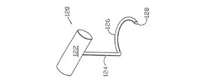
図7eは、操作部122、シャフト124及び先の鋭い又は先の丸い弾丸型の先端128を有するフック126を具えたチューブ設置器具120を示す。図7fは、皮下層8の組織を通るチューブ35を通過して皮膚6に近付ける器具120を示す。チューブ35に形成された切り欠き136によって先端128をチューブ35の突き当たり134に受容する。器具120を強く押すことにより、符号138で示すように皮膚6をテント状にすることが可能であり、皮膚6を外科用メス140で切開することができ、チューブ35を患者から出して上記の図4a−fに示すように適切な終端構成が可能となる。
FIG. 7e shows the
図8は、剥離204の中で概して端部と端部を接するよう設けた1対のスクリーン14を具えた閉塞システム202の改良型の実施例を示す。移送部材サブアッセンブリ59が剥離204の上に設けられており、膜ドレープ205がそれらの上に設けられている。チューブ35は、(例えば、上記のような手段及びチューブ設置器具120を用いて)剥離204の双方の側の組織を通り抜けて、移送部材アッセンブリ59の両側で皮膚6を出る。チューブ35は、符号206で結ばれている。このように、チューブ35は、剥離204に閉塞システム202を固定するための縫合糸又はリテーナとして機能する。チューブの端部38a又は40aをこのような目的のために使用できるため、他のチューブの端部が上記のような1又はそれ以上の入力/出力サブシステム18と流通し得るような状態となる。
FIG. 8 shows an improved embodiment of an
クリップ等といった皮膚6の上に設けられた適切な締結具によってチューブ35を固定することができる。さらに、スクリーン14を重ね合わせ、隣接させ、わずかにか間隔を空けて及びそうでなければ必要に応じて特定の組織の剥離のために構成及び設置できる。さらに、スクリーン14を必要に応じて切り取るよう構成できる。
The
図9は、先の鋭い遠位端224及び複数の環状の頂部226aを具えた近位端226を有するトロカール器具222を具えたチューブ/縫合糸サブアッセンブリ220の改良型実施例を示す。柔軟性のあるチューブ228は、スクリーン周縁部材及び縫合糸の機能を合わせる。柔軟性のあるチューブ228は、針の近位端226に取り外し可能に取り付けられるよう構成された端部228aを終端とし、その結果、頂部226aによって所定の位置に保持される。チューブ228は、上記のようにスクリーン14に任意に結合されており、上記のように入力/出力サブシステム18とともに流体の排出及び又は潅注のための穿孔228bを有し得る。チューブ/縫合糸サブアッセンブリ220は所定の位置にスクリーン14を固定して組織の近くにチューブ228を通すことによって剥離4を閉塞するよう構成される。チューブ/縫合糸サブアッセンブリ220及びスクリーン14を、傷及び切開を含む剥離の閉塞及び治療のために予め包装し且つ予め殺菌できる。
FIG. 9 illustrates an improved embodiment of a tube /
図10,11a及び11bは、スクリーン周縁部材を具えた第1及び第2の縫合糸サブアッセンブリ304,306を具えた閉塞スクリーンシステム302の改良した実施例を示す。縫合糸サブアッセンブリ304,306は、それぞれ湾曲した針304a,306aを有しており、それらはスエージ加工され、普通の長さの縫合糸307の反対側の端部304b,306bに接着結合されている。縫合糸307を吸収性又は非吸収性とすることが可能である。図10に示すように、スクリーン閉塞システム302をスクリーン308の周縁に取り外し可能に固定された縫合糸307で予め組み立てることができる。スクリーン308の組み立てに先だって、縫合糸307を部分的又は完全に切断又は分断することができる。例えば、縫合糸307をスクリーンの端部310a,310bに沿ってそれぞれ離すことで、スクリーンの下縁312に沿ってのみ縫合糸を固定できる。
FIGS. 10, 11a and 11b show an improved embodiment of an
使用時に、縫合糸サブアッセンブリ304,306は、縫合糸/スクリーン閉塞システム302を取り付け易くすることで、剥離4に固定するために必要な部品を組み込んだ予め組み立てた器具を設けることができる。例えば、剥離4の下部に位置する組織部に縫合糸サブアッセンブリ304,306を通すことによって、スクリーン308を下部のみで固定できる。代替的に、縫合糸サブアッセンブリ304,306を近くの組織に通して皮膚6の面から出すことができ、縫合糸サブアッセンブリ304,306を使用して皮膚6で剥離4を閉塞できる。返しを有するストランド320は、上記のように組織部分12a,bと作用できることで、スクリーン308が分かれた組織部12a,b間の比較的確実な機械的な結合を与える。縫合糸サブアッセンブリ304,306を、皮膚6、深い皮膚層7、皮下層8、及び筋膜10の付着及び仮縫いを含む、剥離4における様々な目的のために使用できる。さらに、縫合糸アッセンブリ304,306の全部又は一部を取り除くことが可能であり、追加の縫合糸サブアッセンブリをスクリーン308に取り付け又は縫合することができる。
In use, the
図11aは、縫合糸307に取り付けられたスクリーン308を示す。図11bは、隣接するそれぞれの縦方向のストランド320の間に設けられた中空の管状の縦方向のライザー324を有する代替的なスクリーン318の構造を示しており、全てのライザー324がスペーサ322によって結合され、流体流れの矢印326で示すように、ライザーの開口端324a及び穿孔324bを介して剥離と連通するよう構成される。スクリーン/縫合糸302の全て又はその部分は、吸収性の材料を具えることができる。
FIG. 11 a shows the
図12,13a及び13bは、スクリーンのみを有する閉塞スクリーンシステム402の改良型の実施例及び適用方法を示す。スクリーン又はメッシュ404は、上記のような返しを有するストランド30を具えたスクリーン14と同様に、第1の組織部分12aに対向して剥離4に設けられる。そして、第2の組織部分12bがスクリーン404に対向して位置するため、スクリーン404の機械的作用によって剥離4を塞いで固定できる。縫合糸、排液チューブ、I/O器具、及び傷の端部12を閉塞し、組織剥離4の内部を排出し、感染と闘い、疼痛管理を行い、本書の他の部分で記載されているような本発明に関する他の全ての機能を目的とする他の補助的な部品をスクリーン404に追加できる。例えば、スクリーン404を皮下のレベル8において縫合糸で固定できる。必要に応じて様々な流体内部結合器具を使用して、流体内部結合器具がその初めの目的を果たした後に取り外すよう構成できる。また、符号59で示した上記(図7d)の実施例といった移送部材サブアッセンブリを使用して、真皮レベル6における外部からの排出を行うことができる。さらに、排出及び潅注チューブをスクリーン404と並べて又はスクリーン404の近くの傷4の中に組み込むことができる。本発明のスクリーンだけのバージョンが、上記の材料を含む様々な適切な生体適合性のある吸収性及び非吸収性の材料を具えることが可能であることに留意されたい。
12, 13a and 13b show an improved embodiment and method of application of a
図13aは、スクリーン404の拡大図であり、特に返しを具えたストランド406及び横方向のスペーサ408を示しており、それらが互いに格子状に結合してスクリーン404を形成する。図13bは、横方向のスペーサ408に間隔を空けて結合された中空のチューブを具える縦方向のライザー412を有する改良型スクリーン410を具えた代替的な実施例を示す。流体は、矢印420の流体流れで示すように、ライザーの開口端412a及び穿孔412bを介して縦方向のライザー412を出入りするよう流れる。
FIG. 13 a is an enlarged view of the
図14aから14gは、本発明に係る方法を利用して組織剥離4に組み込まれ組織剥離4を閉塞するスクリーン404を示す。図14aから14gに示す本方法は、図5aから5e及び図6a,6bに示す方法と同じである。図14cは、スクリーン404を押して剥離の中に案内される方向を示す下向き/内向きの力の矢印54aを表している。
FIGS. 14a to 14g show a
図15a,b及び16a,bは、コネクタ506によって間隔を空けて互いに固定されて束になったチューブ504を具える改良型の縦方向のライザー502を示す。患者の通常の動きによって、縦方向のライザー502を交互に圧縮及び伸長させ易くなるため、矢印510の流体の流れで示すように傷4から流体を移送するための「ポンプ」動作を与える。図15a,bは、伸長形態のライザー502を示す。長手方向(すなわち、端から端)にスクリーン14を圧縮すると、束になったライザー504を図16a,bに示す形態に圧縮し、これにより流体が隙間の空間508の中に引き込まれライザー502が伸びるとそこから圧送される。
FIGS. 15a, b and 16a, b show an improved
図17は、束になったチューブ604を具えた縦方向のライザー602のさらに別の形態を示しており、密着して束になっていて流体を送るための通路6060を規定する。患者の通常の移動に関するポンプ動作によって、このような流体の輸送を強化し得る。返し608が、チューブ604から外側に突出している。撚り(twisted)、編み上げ(braided)等といった、束になったチューブの他の様々な態様を利用できることに留意されたい。
FIG. 17 shows yet another form of
図18は、縦方向のライザー/周縁部材702のさらに別の代替的な実施形態を示す。この部材702は、一般に「溝切り(fluted)」排液チューブと称される態様を有しており、長手方向に延びる通路704を有している。このような形態は、上記のような周縁部材と置き換えることができ、入力/出力サブシステム18を具えて傷4と流通するよう機能し得る。
FIG. 18 illustrates yet another alternative embodiment of a longitudinal riser /
縦方向のライザーに関する追加の代替的な実施形態に関しては、それらは、図3に示すストランド30と同じような返しを有したモノフィラメントのストランド、又は返しの無いモノフィラメントのストランドのいずれかを具え得る。このようなモノフィラメントの縦方向のライザーは、流体がチューブに沿って流れる受動的な排出チューブとして機能し得る。それらは、皮膚6の上を伸びることができ、適切な吸収性材料を具えて様々な態様に形成された移送部材に隣接又は接触する。実施例は、図7dで符号59で示すようなガーゼの包帯及び移送部材サブアッセンブリを有する。
With respect to additional alternative embodiments relating to the longitudinal risers, they may comprise either a monofilament strand having a barb similar to the
図19は、複数の個々の繊維804を撚って編むことによって構成したストランド802の代替的な実施例を示す。先の丸い端部806を終端とするそれぞれの個々の繊維804aによって返し805が形成される。返し805は、概して、ストランド802から外側に突出して、その長手軸に対して鋭角を形成する。それらは、上記のように、剥離4の中の組織に貫入するよう構成される。使用時に、返し805は通常は、概して患者及び組織剥離4の外側を指す方向に向く。
FIG. 19 shows an alternative embodiment of a
図20は、複数の撚って編んだ繊維904を具えたストランド902の別の代替的な実施例を示す。返し905が個々の繊維904aで形成されており、切り欠き908及び先の鋭い端部910を有している。切り欠き908及び端部910は、返し905が剥離の端の組織から容易に引き出され得るよう構成されており、スクリーンが剥離の端部に沿って摺動するよう構成され、適切な位置に達する。
FIG. 20 shows another alternative embodiment of a
図21は、個々の繊維1006を輪にして、繊維の輪のそれぞれの頂点1008から内側に離れた切断位置1010でこれを切断することによって形成された返し1004を具えた、さらに改良したスクリーン1002を示す。使用時に、返し1004が組織にわずかに貫入して組織に埋め込まれる。繊維1006は直径が極細繊維と同じ位に相対的に小さいため、患者の快適性が最適化されていることに留意されたい。
FIG. 21 shows a further improved screen 1002 comprising
図22は、個々の繊維1106を輪にして、繊維の輪のそれぞれの頂点1108から内側に離れた位置1110でこれを切断することによって形成した返し1104を具え、これにより各フック1112を形成した、改良型スクリーン1102のさらに別の実施例を示す。フック1112は、マジックテープ(登録商標)と同じような方法で動き、近くの組織が結合のループ部分を形成する。使用時に、フック1112がわずかに組織に貫入して組織に埋め込まれる。フック1112の形態により剥離4の近くの組織の中にフックを保持し易くなっており、これにより分かれている第1及び第2の組織部分12a,bを閉塞できる。
FIG. 22 comprises a
図23は、上記のスクリーン1002と同じような形態を具えたスクリーン1202を示しており、追加の繊維部材又は繊維1204を具えている。追加の繊維1204は、繊維の返し1206をその上に置き易くなっており、これによりスクリーン1202を傷の剥離の中である方向に向けることができ、上記のスクリーン14と同じような方法で動く。返し1206は、切断位置1210で頂部1208を切断することによって形成される。
FIG. 23 shows a
同様に、図24は、繊維ループ1306に係合して図24に示すように繊維ループ1306を右の方向に向ける追加の繊維1304を具えるスクリーン1302を示す。繊維ループ1306の斜めになった向きにより、スクリーン1302に関して外側に引っ張ることによって、剥離4の近くの組織部分12a,bの中に繊維ループ1306をセットし易い。また、上記のようにスクリーン1320を再配置可能である。繊維ループ1306を繊維ループの頂点1308から内側に離れた切断位置1310で切断でき、これによりフック1312を形成する。
Similarly, FIG. 24 shows a
図21から24が、スクリーンの一方の面から延びる返し及びフックを具えたスクリーンを開示していることに留意されたい。また、本発明は、両面から延びる返し及びフックを具えたスクリーンを有している。 Note that FIGS. 21-24 disclose a screen with barbs and hooks extending from one side of the screen. The present invention also includes a screen having barbs and hooks extending from both sides.
本発明のさらなる改良型の態様又は実施例を具える閉塞スクリーンを図25から図30に示しており、概して符号1402を参照して示す。スクリーン1402は、それぞれのストランド1408が一緒に繋ぎ合わされた複数の個々の結合1406の半独立の動作によって、剥離にわたって近くの組織部分に係合及び接近する柔軟性の高いパネル1404を概して具えている。
An occlusion screen comprising a further improved aspect or embodiment of the present invention is shown in FIGS. 25-30 and generally indicated with
スクリーン1402は、前側及び後側の裏地シート1426,1428を具えた予め組み込んだエン閉塞アッセンブリ1424を有しており、裏地シートには適切な取り除き可能な接着剤1429が設けられている。裏地シート1426,1428は、好適には、取り扱って患者の中に設置する際に閉塞スクリーン1402の平らな形状を保持して鋭い突起部の先端から保護するために、紙又は(比較的薄いパネル1404と比較して)比較的固い他の材質(例えば、Styrofoam.RTM.材料)を具えている。外側端部の操作片1430がパネル1404の周縁1432の上端に取り付けられて(図25)手又は器具で掴むよう構成されており、取り扱い、位置合わせ及び設置がし易くなっている。
The
図26は、組織の剥離4に配置され、鉗子1434といった適切な器具を具えた閉塞スクリーン1402を示している。図27は、取り除かれる裏地片1426及び1428を具えた所定の位置の2枚の閉塞スクリーン1402のパネル1404を示しており、分かれている組織部分12a,bが一緒に押されてパネル1404に近付く。縁部1436を皮膚の表面と同一平面になるよう切り取って、操作片1430に沿って取り除くことができる。閉塞した剥離4を適切なカバー片1438で覆うことができ、これにより、治療の際に剥離4を保護するとともに、組織部分12a,bを一緒に固定するための引っ張り保持力を与えることができる(図28)。
FIG. 26 shows an
図29は、組織の剥離4の所定の位置の閉塞スクリーン1502を示す。図30は、裏地シート1508の取り出しを示しており、これにより、パネル1504が組織部分12bに対向するよう配置され、約1から2mm又は特定の組織の要請によって決まる長さだけ組織の中にパネル1504の突起部を貫入させることによって組織に係合する。
FIG. 29 shows the
図31から図36は、本発明を実施する閉塞スクリーン1502の別の改良型の実施例又は態様の構成及び動作を示す。図31は、組み立てられた閉塞スクリーン1502を示しており、前側及び後側の裏地シート1506,1508が組織に接近するパネル1504を囲んでいる。図32は、閉塞スクリーン1502の分解図を示しており、組織に接近するパネル1504が前側及び後側の裏地シート1506,1508間に配置されるよう構成される。裏地シート1506,1508は、上縁1510,1512をそれぞれ有しており、裏地シートの上縁1512が前側裏地シートの上縁1510よりも高く延びており、鉗子又は他の同じような器具を使って裏地シート1508を上縁1512で掴み易くしている。後側の裏地シートの上縁1512は、好適には、目立つよう、さらには鉗子又は手で上縁1512を掴み易くするようカラー印刷される。図33及び34は、長方形のパネル1504と同じ構成の正方形の閉塞パネル1514を具えた別の実施例の閉塞スクリーン1513を示す。
FIGS. 31-36 illustrate the construction and operation of another improved embodiment or aspect of a
図35は、第1及び第2の分かれた組織部分又は端部12a,bを具えた組織の剥離4を示す。図36は、パネル1514を示す点線を具えた閉塞スクリーン1513の配置を示しており、既に組織の剥離4の所定の位置にある。図36に示すように、組織剥離4を、剥離4の形態に応じて適した大きさ及び数の閉塞パネル1514で「タイル張り」できる。図37は、取り除かれる後側裏地シート1508を具えた所定の位置のスクリーン1502(図31)を示しており、突起部が組織部分12bに晒されて貫入する。反対側の組織部分12aを矢印1516の方向に押して閉塞に近付けることができる。図38は、接近している組織の剥離4の下部(最深部)を示しており、前側裏地シート1506が図39で取り除かれることで図40に示す状態になり、組織の剥離4の下部が閉塞パネル1504に固定され又はこれに「接近」する。図41から図46は、本質的に上記の手順を繰り返すことによって、別の閉塞スクリーン1502に組織の剥離4の上部(又は外側/遠位)を固定することを示している。突出する遠位の縁部1518は、図44に示すように、皮膚の表面と略同一面上の最も外側のパネル1504から取り除かれる。適切なカバー1520が図45に示すように組織の剥離の上に配置される。図46は、組織に突出する係合を示しており、組織の端部12a,bが接近して突起部1522が上向き且つ外向きの方向に向くことで、パネル1504を外側に引っ張るのに応じて組織の端部12a,bを一緒に引き易くなる。様々な実施例の閉塞スクリーンの突起部及びクリップが、曲線状、直線状、鉤形状等を含む、様々な適切な大きさ及び形態を有している。組織剥離4の閉塞及び接近が、テープ、接着剤、ステープル、縫合糸又はNPWT装置、Kinetic Concepts,Inc.of San Antonio,Tex.から入手可能なThe V.A.C.RTM.System.TMといった差圧源を含む他の閉塞器具で補強することが可能であり、閉塞スクリーン又はスクリーンとともに傷の閉塞を促すよう選択できる。
FIG. 35 shows a
図47は、下部の取り除き可能な一片2306を有する裏地シート2304を具えた閉塞スクリーン2302の別の代替的な実施例を示しており、一片2306は、スクリーン2302を始めに位置決めして、その後で裏地シート2304の上部2310を取り除けるようにするためにクリップの最深部の列2308に付いている。
FIG. 47 shows another alternative embodiment of an
図48aからcは、閉塞クリップ2354の列を具えた閉塞スクリーン2352の別の実施例を示しており、閉塞クリップ2354を閉塞スクリーン2352のパネル2358の下端2356に沿って取り付けることができる。各閉塞クリップ2354は、それぞれの組織部分12a,bに貫入するよう構成且つ配置される、横方向に突出するフック2360a,bの第1及び第2の列を有している。組織剥離4の下部又は内部を閉塞するための連続的な手順は、図48aに示すように、閉塞クリップ2354を組織剥離4の中に配置することに始まる。フック2360aの第1の列を、例えば、パネル2358を傾けて操作することによって(図48b)、第1の組織部分12aに埋め込むことができる。剥離した第2の組織部分12b(図48c)にフック2360bの第2の列を埋め込むことによって、例えば、パネル2358を傾けて操作することによって、閉塞を行うことができる。閉塞クリップ2354を具える閉塞スクリーン2352を閉塞スクリーン2302の閉塞アッセンブリとともに使用して、リンク2308の下部の列を、閉塞スクリーンを始めに固定するのとともに閉塞クリップ2354を補うよう晒すことができる。リンクの各列の下端部、リンクの一つおきの列の下端部等のクリップ2354を含む、適切な数及び間隔でクリップ2354を設けることができる。
48a-c show another embodiment of a
図49は、閉塞スクリーン2402の追加の代替的な実施例を示しており、裏地2406に別個のクリップ2404を取り付けることによって構成され、適切な接着剤又は他の手段を予め組み込むことによってクリップ2404を保持できる。図50は、閉塞スクリーン2502のさらに別の代替的な実施例を示しており、スクリーン2402と同じであるが少数の異なるクリップ2504を具えている。クリップ2504は、クリップ2504の本体2508に対して外側に凸状に湾曲する突起部2506を有している。突起部2506の反りにより、剥離した組織部分12a,bへの貫入及びこれらの閉塞をし易くすることができる。また、突起部2506は、直線状、返しを有する等とすることができ、クリップ2504の本体2508に対して任意の適した角度に向けることができる。
FIG. 49 shows an additional alternative embodiment of an
図51及び52は、腹部の切開1904に適用される閉塞スクリーン1902を示す。このような切開は、一般に、腹部の外科手術に含まれ、感染並びに閉塞及び治癒の困難を含む様々な問題をもたらす可能性がある。腹腔の中の腹部の組織は、周囲部1906に晒されている。スクリーン1902に複数の硬質又は半硬質の折り畳めない部材1908を設けることができ、その全体的な形状及びその腹腔、好適には周囲部1906の近傍への配置し易さを維持する。スクリーン1902は、中央線1916に対して逆方向に向いた突起部1910を有しており、閉塞の中央に向けて切開1904の反対側に向いている。スクリーン1902に、好適には組織の剥離の周囲部1906の近くにスクリーンを配置及び保持するような大きさで構成された周縁部材1912を設けることができる。比較的広い範囲の腹部の組織の剥離をこのようにして実現でき、折り畳めない部材1908及び周縁部材1912を組み合わせた位置決め効果を特に具えている。また、適切な切開及び突起部の向きを具えているため、本器具はプレ腹膜位置及び筋肉組織に、さらに図示するように、腹部の内部の筋肉組織の下方に配置できる。
51 and 52 show an
本発明の特定の形態を本書で図示及び説明する一方、本発明は、説明及び図示した部分の特定の形態又は構成に限定されないことに留意されたい。 While specific forms of the invention are illustrated and described herein, it should be noted that the invention is not limited to the specific forms or configurations of the parts described and illustrated.
Claims (17)
それぞれが組織に貫通するよう構成された突起部を有する複数のクリップと;
前記クリップを柔軟に結合する柔軟性のあるリンクと;
を有することを特徴とするクリップシステム。 A medical occlusion clip system for occluding a detachment between a first and second tissue section, the system comprising:
A plurality of clips each having a protrusion configured to penetrate tissue;
A flexible link that flexibly couples the clip;
A clip system comprising:
前記柔軟性のあるリンクが、前記クリップを取り付け前記クリップに結合される複数の繊維を有する柔軟性のある材料のスクリーンを具えることを特徴とするクリップシステム。 The clip system according to claim 1.
The clip system wherein the flexible link comprises a screen of flexible material having a plurality of fibers attached to the clip and coupled to the clip.
各前記クリップが、別の前記クリップに柔軟に結合されて前記柔軟性のあるリンクを形成する各前記突起部及び係合部を形成する曲げワイヤの長さを具えることを特徴とするクリップシステム。 The clip system according to claim 2, wherein
A clip system, wherein each clip comprises a length of a bending wire forming each projection and engagement portion that is flexibly coupled to another clip to form the flexible link. .
第1の方向を有し前記第1の組織部に係合するよう構成された突起部を有する前記クリップの第1のセットと;
第2の方向を有し前記第2の組織部に係合するよう構成された突起部を有する前記クリップの第2のセットと;
を有することを特徴とするクリップシステム。 The clip system according to claim 1.
A first set of clips having protrusions configured to engage the first tissue portion in a first direction;
A second set of clips having a protrusion having a second direction and configured to engage the second tissue portion;
A clip system comprising:
対向する第1及び第2の面を有する柔軟性のあるスクリーンを有しており、
前記クリップの第1のセットの前記突起部が、前記スクリーンの前記第1の面から延びており、
前記クリップの第2のセットの前記突起部が、前記スクリーンの前記第2の面から延びており、
前記スクリーンが、前記クリップの第1のセットを取り付けた第1の部分を有しており、
前記スクリーンが、前記クリップの第2のセットを取り付けた第2の部分を有しており、
前記クリップの第1及び第2のセットのそれぞれの前記突起部が、前記組織の剥離にわたって張力を適用するよう互いに反対方向に向いていることを特徴とするクリップシステム。 The clip system according to claim 4, wherein
A flexible screen having opposing first and second surfaces;
The protrusions of the first set of clips extend from the first surface of the screen;
The protrusions of the second set of clips extend from the second surface of the screen;
The screen has a first portion with a first set of clips attached thereto;
The screen has a second portion with a second set of clips attached thereto;
A clip system wherein the protrusions of each of the first and second sets of clips are oriented in opposite directions to apply tension across the tissue detachment.
前記クリップが、それぞれがループを有するリンクを具えており、
前記リンクの複数の連接ストランドが、そのそれぞれのループで相互連結されており、
前記連接ストランドが柔軟に相互連結されていることを特徴とするクリップシステム。 The clip system according to claim 1.
The clips comprise links each having a loop;
A plurality of articulated strands of the link are interconnected by their respective loops;
A clip system characterized in that the connecting strands are flexibly interconnected.
第1及び第2のループ及び第1及び第2の突起部を有するそれぞれの前記クリップと;
連接結合によって結合された各第1及び第2のループで隣接するクリップを相互連結することによって形成される複数の柔軟性のあるストランドと;
前記ストランド及び前記ストランドにわたって延在しこれに結合された複数の柔軟性のある繊維を有するスクリーンと;
を有することを特徴とするクリップシステム。 The clip system according to claim 6.
Each said clip having first and second loops and first and second protrusions;
A plurality of flexible strands formed by interconnecting adjacent clips in each first and second loop joined by an articulated bond;
A screen having said strands and a plurality of flexible fibers extending across and bonded to said strands;
A clip system comprising:
前記それぞれのクリップが、外側に突出する各突起部を具えたクリップ本体を有しており、
前記クリップが、前記スクリーンに別々に柔軟に取り付けられていることを特徴とするクリップシステム。 The clip system according to claim 7,
Each of the clips has a clip body with each protrusion protruding outward,
The clip system, wherein the clip is separately and flexibly attached to the screen.
前記各クリップ本体が、開口部を有しており、
前記スクリーンが、前記クリップ本体の開口部を通過する複数の繊維を具えることを特徴とするクリップシステム。 The clip system according to claim 8,
Each clip body has an opening,
The clip system, wherein the screen includes a plurality of fibers that pass through openings in the clip body.
前記スクリーンが、複数の柔軟性のある裏地片を有しており、
複数のクリップが、前記裏地片を通して延びる各クリップの突起部を具えたそれぞれの前記裏地片に取り付けられており、
前記スクリーンの複数の繊維が、略平行に間隔を空けた関係で、前記裏地片間を延びており柔軟に相互連結されていることを特徴とするクリップシステム。 The clip system according to claim 9,
The screen has a plurality of flexible backing pieces;
A plurality of clips are attached to each of the backing pieces with the protrusions of each clip extending through the backing piece,
A clip system wherein a plurality of fibers of the screen extend between the backing pieces and are flexibly interconnected in a generally parallel spaced relationship.
それぞれの前記クリップが、第1及び第2の面及び前記第1及び第2の面からそれぞれ延びる第1及び第2の突起部を有することを特徴とするクリップシステム。 The clip system according to claim 1.
Each clip has first and second surfaces and first and second protrusions extending from the first and second surfaces, respectively.
前記クリップ本体をほぼ囲み切り欠き部を有する周縁部と;
前記クリップ本体の開口部と;
前記クリップ本体の前記開口部に隣接する前記周縁部の内側に間隔を空けた関係で設けられた内部の突起部と;
前記切り欠き部に隣接して前記クリップの周縁部に設けられたエッジ突起部と;
を有することを特徴とするクリップシステム。 9. The clip system of claim 8, wherein each of the clips is:
A peripheral portion substantially surrounding the clip body and having a notch;
An opening in the clip body;
An internal protrusion provided in a spaced relationship inside the peripheral edge adjacent to the opening of the clip body;
An edge protrusion provided on a peripheral edge of the clip adjacent to the notch;
A clip system comprising:
第1及び第2の面を有する前記クリップ本体と;
前記クリップ本体の第1及び第2の面からそれぞれ反対方向に外側に突出する第1及び第2の内部の突起部と;
前記クリップ本体の第1及び第2の面からそれぞれ反対方向に外側に突出する第1及び第2のエッジ突起部と;
を有することを特徴とするクリップシステム。 13. The clip system according to claim 12, wherein each of the clips is
The clip body having first and second surfaces;
First and second internal protrusions protruding outward in opposite directions from the first and second surfaces of the clip body;
First and second edge protrusions protruding outward in opposite directions from the first and second surfaces of the clip body, respectively;
A clip system comprising:
負圧源と;
前記負圧源に結合され負圧を分配するためのマニホルドと;
前記分配するための手段を前記組織の剥離に流体結合する結合部と;
を有することを特徴とするクリップシステム。 The clip system according to claim 1.
A negative pressure source;
A manifold coupled to the negative pressure source for distributing negative pressure;
A coupling fluidly coupling the means for dispensing to the tissue detachment;
A clip system comprising:
前記負圧源が真空源を具えており、
前記マニホルドが発泡材料を具えており、
前記発泡材料が、前記組織の剥離に又はそれに隣接して位置していることを特徴とするクリップシステム。 The clip system according to claim 14,
The negative pressure source comprises a vacuum source;
The manifold comprises a foam material;
A clip system, wherein the foam material is located at or adjacent to the tissue exfoliation.
前記クリップを有する柔軟性のある医療用閉塞スクリーンと;
前記組織の剥離を超えて延在するよう構成されたスクリーンの延長部と;
皮膚面に前記スクリーンの延長部を取り付けるよう構成された取り付け部と;
を有することを特徴とするクリップシステム。 The clip system according to claim 1.
A flexible medical occlusion screen having the clip;
An extension of the screen configured to extend beyond the tissue exfoliation;
An attachment configured to attach an extension of the screen to the skin surface;
A clip system comprising:
接着剤、ステープル及び縫合糸を有する群のうちの1つを具える前記取り付け部と;
皮膚面に前記スクリーンの延長部を結合するよう構成された疎水性発泡材料を具える流体移送要素と;
前記流体移送要素及び皮膚面への取り付け部の上方に配置するよう構成されたドレープと;
前記流体移送要素に流体結合された負圧源と;
を有することを特徴とするクリップシステム。 The clip system according to claim 16, wherein
Said attachment comprising one of the group comprising adhesives, staples and sutures;
A fluid transfer element comprising a hydrophobic foam material configured to couple an extension of the screen to a skin surface;
A drape configured to be disposed above the fluid transfer element and attachment to the skin surface;
A negative pressure source fluidly coupled to the fluid transfer element;
A clip system comprising:
Priority Applications (1)
| Application Number | Priority Date | Filing Date | Title |
|---|---|---|---|
| JP2011230116A JP2012050840A (en) | 2011-10-19 | 2011-10-19 | Medical closure clip system |
Applications Claiming Priority (1)
| Application Number | Priority Date | Filing Date | Title |
|---|---|---|---|
| JP2011230116A JP2012050840A (en) | 2011-10-19 | 2011-10-19 | Medical closure clip system |
Related Parent Applications (1)
| Application Number | Title | Priority Date | Filing Date |
|---|---|---|---|
| JP2009505347A Division JP2009533136A (en) | 2006-04-13 | 2006-04-13 | Medical occlusion screen mounting system and method |
Publications (1)
| Publication Number | Publication Date |
|---|---|
| JP2012050840A true JP2012050840A (en) | 2012-03-15 |
Family
ID=45904867
Family Applications (1)
| Application Number | Title | Priority Date | Filing Date |
|---|---|---|---|
| JP2011230116A Pending JP2012050840A (en) | 2011-10-19 | 2011-10-19 | Medical closure clip system |
Country Status (1)
| Country | Link |
|---|---|
| JP (1) | JP2012050840A (en) |
Cited By (1)
| Publication number | Priority date | Publication date | Assignee | Title |
|---|---|---|---|---|
| JP2017533803A (en) * | 2014-10-31 | 2017-11-16 | プリヴェント パッチ リミテッド ライアビリティ カンパニー | Apparatus and method for preventing scar hernia |
Citations (2)
| Publication number | Priority date | Publication date | Assignee | Title |
|---|---|---|---|---|
| US20020077661A1 (en) * | 2000-12-20 | 2002-06-20 | Vahid Saadat | Multi-barbed device for retaining tissue in apposition and methods of use |
| US20050182445A1 (en) * | 2002-08-21 | 2005-08-18 | Kci Licensing, Inc. | Circumferential medical closure device and method |
-
2011
- 2011-10-19 JP JP2011230116A patent/JP2012050840A/en active Pending
Patent Citations (2)
| Publication number | Priority date | Publication date | Assignee | Title |
|---|---|---|---|---|
| US20020077661A1 (en) * | 2000-12-20 | 2002-06-20 | Vahid Saadat | Multi-barbed device for retaining tissue in apposition and methods of use |
| US20050182445A1 (en) * | 2002-08-21 | 2005-08-18 | Kci Licensing, Inc. | Circumferential medical closure device and method |
Cited By (1)
| Publication number | Priority date | Publication date | Assignee | Title |
|---|---|---|---|---|
| JP2017533803A (en) * | 2014-10-31 | 2017-11-16 | プリヴェント パッチ リミテッド ライアビリティ カンパニー | Apparatus and method for preventing scar hernia |
Similar Documents
| Publication | Publication Date | Title |
|---|---|---|
| US7410495B2 (en) | Medical closure clip system and method | |
| US8062331B2 (en) | Internal and external medical closure screen systems and methods | |
| US7413571B2 (en) | Flexible medical closure screen and method | |
| US7413570B2 (en) | Medical closure screen installation systems and methods | |
| US8123781B2 (en) | Screen devices and methods for closing tissue separations | |
| AU2006342253B2 (en) | Medical closure screen installation systems and methods | |
| US7351250B2 (en) | Circumferential medical closure device and method | |
| US11419767B2 (en) | Negative pressure wound closure device and systems and methods of use in treating wounds with negative pressure | |
| US10010710B2 (en) | Rapid closing surgical closure device | |
| AU2010303915B2 (en) | Rapid closing surgical closure device | |
| JP2019528151A (en) | Negative pressure wound closure device | |
| JP2009533204A (en) | Medical occlusion clip system and method | |
| WO2017044120A1 (en) | Rapid closing surgical closure device | |
| KR20090027188A (en) | Medical Suture Clip Systems and Methods | |
| JP2012050840A (en) | Medical closure clip system | |
| HK1129059A (en) | Medical closure clip system and method |
Legal Events
| Date | Code | Title | Description |
|---|---|---|---|
| A521 | Written amendment |
Free format text: JAPANESE INTERMEDIATE CODE: A523 Effective date: 20121004 |
|
| A131 | Notification of reasons for refusal |
Free format text: JAPANESE INTERMEDIATE CODE: A131 Effective date: 20130402 |
|
| A02 | Decision of refusal |
Free format text: JAPANESE INTERMEDIATE CODE: A02 Effective date: 20130903 |