JP2012042242A - Antenna characteristic measurement system and antenna characteristic measurement method - Google Patents
Antenna characteristic measurement system and antenna characteristic measurement method Download PDFInfo
- Publication number
- JP2012042242A JP2012042242A JP2010181623A JP2010181623A JP2012042242A JP 2012042242 A JP2012042242 A JP 2012042242A JP 2010181623 A JP2010181623 A JP 2010181623A JP 2010181623 A JP2010181623 A JP 2010181623A JP 2012042242 A JP2012042242 A JP 2012042242A
- Authority
- JP
- Japan
- Prior art keywords
- antenna
- measurement
- characteristic
- point
- gain
- Prior art date
- Legal status (The legal status is an assumption and is not a legal conclusion. Google has not performed a legal analysis and makes no representation as to the accuracy of the status listed.)
- Pending
Links
Images


Classifications
-
- G—PHYSICS
- G01—MEASURING; TESTING
- G01R—MEASURING ELECTRIC VARIABLES; MEASURING MAGNETIC VARIABLES
- G01R29/00—Arrangements for measuring or indicating electric quantities not covered by groups G01R19/00 - G01R27/00
- G01R29/08—Measuring electromagnetic field characteristics
- G01R29/10—Radiation diagrams of antennas
Landscapes
- Physics & Mathematics (AREA)
- Electromagnetism (AREA)
- General Physics & Mathematics (AREA)
- Monitoring And Testing Of Transmission In General (AREA)
- Mobile Radio Communication Systems (AREA)
Abstract
【課題】アンテナ特性の測定時間を短縮化して測定効率を向上させる。
【解決手段】測定ポイント走査部は、測定ポイントを走査する。アンテナゲイン測定部は、複数の測定ポイント毎のアンテナゲインを測定し、全測定ポイントの中から基準ポイントを設定して、基準ポイントにおけるアンテナゲインと、他測定ポイントにおけるアンテナゲインとの差分であるアンテナゲイン差分値を求める。アンテナ特性測定部は、基準ポイントにおけるアンテナ特性である基準アンテナ特性を測定する。そして、基準アンテナ特性をアンテナゲイン差分値で補正し、他測定ポイントにおけるアンテナ特性を求める。
【選択図】図1An antenna characteristic measurement time is shortened to improve measurement efficiency.
A measurement point scanning unit scans a measurement point. The antenna gain measurement unit measures the antenna gain for each of a plurality of measurement points, sets a reference point among all the measurement points, and an antenna that is a difference between the antenna gain at the reference point and the antenna gain at other measurement points. Find the gain difference value. The antenna characteristic measurement unit measures a reference antenna characteristic that is an antenna characteristic at the reference point. Then, the reference antenna characteristic is corrected with the antenna gain difference value, and the antenna characteristic at another measurement point is obtained.
[Selection] Figure 1
Description
本発明は、アンテナ特性の測定を行うアンテナ特性測定システムおよびアンテナ特性測定方法に関する。 The present invention relates to an antenna characteristic measurement system and an antenna characteristic measurement method for measuring antenna characteristics.
携帯電話器や通信機器を内蔵したノートパソコンといった移動体通信機器のアンテナ特性を含めた、通信性能(受信感度・放射電力)を測定する場合には、電波暗室において、移動体通信機器の回路や構造自体がアンテナ特性に与える影響を明らかにすることが重要である。 When measuring communication performance (receiver sensitivity and radiated power) including antenna characteristics of mobile communication devices such as portable telephones and laptop computers with built-in communication devices, the circuits of mobile communication devices and It is important to clarify the effect of the structure itself on the antenna characteristics.
このような移動体通信機器の通信性能の測定には、被測定機器に対して全立体角を走査可能な球面上で通信機器の電磁界を測定できる球面測定が用いられる。
従来技術として、反射板によって被測定アンテナからの放射電力を上半球面に集中させてアンテナ放射特性を測定する技術が提案されている(特許文献1)。また、シールド室内を反射体で球状に形成した電磁波測定箱が提案されている(特許文献2)。
For measuring the communication performance of such a mobile communication device, spherical measurement that can measure the electromagnetic field of the communication device on a spherical surface capable of scanning all solid angles with respect to the device under measurement is used.
As a conventional technique, a technique has been proposed in which antenna radiation characteristics are measured by concentrating radiated power from an antenna under measurement on an upper hemisphere using a reflector (Patent Document 1). Further, an electromagnetic wave measurement box in which the shield chamber is formed in a spherical shape with a reflector has been proposed (Patent Document 2).
上記のような球面測定では、アンテナが設置される被測定機器を囲む球面上の複数の測定ポイント(例えば、264箇所の測定ポイント)について、該被測定機器の受信感度および放射電力を測定して、球面上での通信性能を評価することが行われる。 In the spherical measurement as described above, the reception sensitivity and radiated power of the device under test are measured at a plurality of measurement points (for example, 264 measurement points) on the spherical surface surrounding the device under test where the antenna is installed. The communication performance on the spherical surface is evaluated.
特に受信感度の測定では、まず、測定用アンテナから被測定機器に設置される被測定用アンテナへ電波を放射して、通信性能を測定する擬似基地局と被測定機器との間で通信状態を確立させる。そして、通信確立後に、被測定機器が一定のエラーレートを表示するときの受信レベルを測定する。 Particularly in the measurement of reception sensitivity, first, radio waves are radiated from the measurement antenna to the antenna under measurement installed in the device under test, and the communication state is measured between the pseudo base station that measures the communication performance and the device under measurement. Establish. Then, after communication is established, the reception level when the device under test displays a certain error rate is measured.
例えば、被測定機器が規定のエラーレートになるまで、受信レベルを0.1dBステップ(およそ20dB間)低下させていって、規定エラーレートとなる受信レベルを求める。規定エラーレートを表示させる最小の受信レベルが、該測定ポイントにおける受信感度となる。このような測定を行うことで、受信レベルがどこまで低下すれば受信限界になるかといったことを評価することができる。 For example, the reception level is reduced by 0.1 dB steps (approximately 20 dB) until the device under test has a specified error rate, and the reception level at which the specified error rate is obtained is obtained. The minimum reception level that displays the specified error rate is the reception sensitivity at the measurement point. By performing such a measurement, it is possible to evaluate to what extent the reception level is reduced to reach the reception limit.
しかし、このような受信感度測定は、球面上のすべての測定ポイントにおいて、1つの測定ポイントにつき複数の周波数の電波を用いて測定を行うために、多大な測定時間(例えば、1周波数バンド当たり26時間)を要するといった問題があった。 However, since such reception sensitivity measurement is performed using radio waves of a plurality of frequencies at one measurement point at all measurement points on the spherical surface, it takes a great amount of measurement time (for example, 26 per frequency band). Time).
また、被測定機器の受信限界まで受信レベルを低下させるといったことを行うので、通信状態が途中で切断するケースも発生し、この場合には、通信確立の再設定と再測定とを行うことになる。このように、従来のアンテナ特性の測定では、膨大な測定時間を要しており、効率のよい測定が行われていなかった。 In addition, since the reception level is lowered to the reception limit of the device under test, there are cases where the communication state is cut off in the middle, and in this case, the communication establishment is reset and remeasured. Become. As described above, the measurement of the conventional antenna characteristics requires an enormous measurement time, and an efficient measurement has not been performed.
本発明はこのような点に鑑みてなされたものであり、球面の受信感度・放射電力の測定時間を短縮化して測定効率を向上させたアンテナ特性測定システムを提供することを目的とする。 The present invention has been made in view of these points, and an object of the present invention is to provide an antenna characteristic measurement system that improves measurement efficiency by shortening the measurement time of spherical reception sensitivity and radiated power.
また、本発明の他の目的は、球面の受信感度・放射電力の測定時間を短縮化して測定効率を向上させたアンテナ特性測定方法を提供することである。 Another object of the present invention is to provide an antenna characteristic measuring method that improves the measurement efficiency by shortening the measurement time of the reception sensitivity and radiation power of a spherical surface.
上記課題を解決するために、アンテナ特性測定システムが提供される。アンテナ特性測定システムは、測定ポイントを走査する測定ポイント走査部と、被測定用アンテナのアンテナゲインを測定するアンテナゲイン測定部と、前記被測定用アンテナのアンテナ特性を測定するアンテナ特性測定部と、を含む測定制御部とを備え、前記アンテナゲイン測定部は、複数の前記測定ポイント毎の前記アンテナゲインを測定し、全測定ポイントの中から基準ポイントを設定して、前記基準ポイントにおける前記アンテナゲインと、他測定ポイントにおける前記アンテナゲインとの差分であるアンテナゲイン差分値を求め、前記アンテナ特性測定部は、前記基準ポイントにおける前記アンテナ特性である基準アンテナ特性を測定し、前記基準アンテナ特性を前記アンテナゲイン差分値で補正して、前記他測定ポイントにおける前記受信感度・放射電力を求める。 In order to solve the above problems, an antenna characteristic measurement system is provided. The antenna characteristic measurement system includes a measurement point scanning unit that scans a measurement point, an antenna gain measurement unit that measures an antenna gain of the antenna under measurement, an antenna characteristic measurement unit that measures the antenna characteristic of the antenna under measurement, The antenna gain measurement unit measures the antenna gain for each of the plurality of measurement points, sets a reference point from among all the measurement points, and sets the antenna gain at the reference point. And an antenna gain difference value that is a difference from the antenna gain at another measurement point, the antenna characteristic measurement unit measures the reference antenna characteristic that is the antenna characteristic at the reference point, and the reference antenna characteristic is Correct at the antenna gain difference value, and at the other measurement points. Determining the reception sensitivity and radiation power.
受信感度・放射電力の測定時間を短縮化して測定効率を向上させることが可能になる。 It is possible to improve the measurement efficiency by shortening the measurement time of reception sensitivity and radiated power.
以下、本発明の実施の形態を図面を参照して説明する。図1はアンテナ特性測定システムの構成例を示す図である。アンテナ特性測定システム1は、測定ポイント走査部20と測定制御部10とを備える。
Hereinafter, embodiments of the present invention will be described with reference to the drawings. FIG. 1 is a diagram illustrating a configuration example of an antenna characteristic measurement system. The antenna
測定ポイント走査部20は、被測定用アンテナ3aのアンテナ特性を測定する際の測定ポイントを走査する。測定制御部10は、アンテナゲイン測定部11、アンテナ特性測定部12および制御部13を含む。
The measurement
アンテナゲイン測定部11は、被測定用アンテナ3aのアンテナゲインを測定する。アンテナ特性測定部12は、被測定用アンテナ3aのアンテナ特性を測定する。制御部13は、アンテナゲイン測定部11およびアンテナ特性測定部12に対する設定制御等を行い、また測定ポイント走査部20に対する測定ポイントの走査制御を行う。
The antenna
ここで、アンテナゲイン測定部11は、複数の測定ポイント毎のアンテナゲインを測定し、全測定ポイントの中から基準ポイントを設定する。そして、基準ポイントにおけるアンテナゲインと、他測定ポイントにおけるアンテナゲインとの差分であるアンテナゲイン差分値を求める。
Here, the antenna
また、アンテナ特性測定部12は、基準ポイントにおけるアンテナ特性である基準アンテナ特性を測定する。そして、基準アンテナ特性をアンテナゲイン差分値で補正して、他測定ポイントにおけるアンテナ特性を求める(詳細は後述)。
The antenna
次に具体的なシステム構成について説明する。図2はアンテナ特性測定システムの構成例を示す図である。アンテナ特性測定システム1−1は、電波暗室などに配置され、球面上を走査する測定ポイントにおいて、アンテナ特性を測定するシステムである。 Next, a specific system configuration will be described. FIG. 2 is a diagram illustrating a configuration example of an antenna characteristic measurement system. The antenna characteristic measurement system 1-1 is a system that measures an antenna characteristic at a measurement point that is arranged in an anechoic chamber or the like and scans on a spherical surface.
アンテナ特性測定システム1−1は、回転台20a、測定用アンテナ移動部20b、ネットワークアナライザ11a、擬似基地局12aおよび端末装置13aを備える。なお、回転台20aと測定用アンテナ移動部20bは、測定ポイント走査部20の機能に含まれる。また、ネットワークアナライザ11aは、アンテナゲイン測定部11に該当し、擬似基地局12aは、アンテナ特性測定部12に該当し、端末装置13aは、制御部13に該当する。
The antenna characteristic measurement system 1-1 includes a
回転台20aは、被測定機器3を置く台であって、水平面方向に360度の回転が可能である。測定用アンテナ移動部20bは、測定用アンテナ21b、アーム22bおよびアーム駆動部23b、アーム支持部24bを含む。
The
アーム22bの一端には測定用アンテナ21bが取り付けられ、アーム22bの他端はアーム駆動部23bに設置される。アーム22bは、アーム駆動部23bとの接続箇所を基準にして垂直面方向(上下方向)に移動可能である。
The
ネットワークアナライザ11aは、一方のケーブルを介して被測定機器3と接続し、他方のケーブルを介して測定用アンテナ21bと接続する。また、ケーブルのつなぎかえを行うことで、擬似基地局12aは、一方のケーブルを介して被測定機器3と接続し、他方のケーブルを介して測定用アンテナ21bと接続する。
The
端末装置13aは、ネットワークアナライザ11aと擬似基地局12aに接続し、ネットワークアナライザ11aと擬似基地局12aに対する設定制御や、アンテナ特性測定結果の表示制御などを行う。
The
また、端末装置13aは、回転台20aおよび測定用アンテナ移動部20bと接続し、回転台20aの回転駆動制御およびアーム22bの駆動制御を行って、球面上の測定ポイントの走査設定に関する制御を行う。
In addition, the
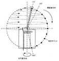
次に測定ポイントについて説明する。図3は測定ポイントを示す図である。アンテナ特性測定システム1−1では、回転台20aに置かれた被測定機器3を囲む球面上のすべての測定ポイントについてのアンテナ特性を評価する。
Next, measurement points will be described. FIG. 3 is a diagram showing measurement points. In the antenna characteristic measurement system 1-1, the antenna characteristics are evaluated for all measurement points on the spherical surface surrounding the device under
測定ポイントの走査としては、例えば、水平面の360°の範囲に対して15°ステップ、垂直面の15°〜165°の範囲に対して15°ステップで測定ポイントを走査する。 As scanning of the measurement point, for example, the measurement point is scanned at a step of 15 ° with respect to a range of 360 ° on a horizontal plane and at a step of 15 ° with respect to a range of 15 ° to 165 ° on a vertical plane.
なお、垂直面のアーム移動では、アーム22bの移動範囲を0°〜180°とはせずに、アーム22bの一端に取り付けた測定用アンテナ21bが天井または床面に接しないように、15°〜165°の範囲としている。
In the vertical arm movement, the movement range of the
水平面の360°の範囲に対して15°刻みなので水平面方向の測定ポイント数は24箇所であり、垂直面の15°〜165°の範囲に対して15°刻みの測定ポイント数は11箇所である。したがって、このときの球面上の測定ポイント数は、264(=11×24)ポイントとなる。 The number of measurement points in the horizontal plane direction is 24 in steps of 15 ° relative to the 360 ° range of the horizontal plane, and the number of measurement points in 15 ° increments is 11 in the range of 15 ° to 165 ° on the vertical plane. . Accordingly, the number of measurement points on the spherical surface at this time is 264 (= 11 × 24) points.
走査の仕方としては、例えば、アーム22bを15°に設定し、回転台20aを15°ステップで回転させて、15°の位置にある測定用アンテナ21bに対する、24箇所を走査する。
As a scanning method, for example, the
同様にして、アーム22bを30°に設定し、回転台20aを15°ステップで回転させて、30°の位置にある測定用アンテナ21bに対する、24箇所を走査する。このような走査をアーム22bが165°になるまで行うので、球面1回分の測定ポイント走査では、264箇所の走査を行うことになる。
Similarly, the
次にアンテナ特性の測定動作について説明する。アンテナ特性の測定として、被測定機器3に設置されている被測定用アンテナ3a(以下、設置アンテナ3a)の受信感度および放射電力を測定する。
Next, the antenna characteristic measurement operation will be described. As measurement of the antenna characteristics, the reception sensitivity and radiated power of the antenna for
図4はアンテナ特性測定動作の全体フローチャートである。
〔S1〕空間減衰量を含めたシステムの減衰量を測定する。
〔S2〕ステップS1で測定した減衰量の較正(calibration)を行い、球面上の全測定ポイントに対する、設置アンテナ3a単体のアンテナゲインを測定する。
FIG. 4 is an overall flowchart of the antenna characteristic measurement operation.
[S1] The system attenuation including the spatial attenuation is measured.
[S2] The attenuation measured in step S1 is calibrated, and the antenna gain of the installed
〔S3〕全測定ポイントの中から基準ポイントPrを設定する。
〔S4〕基準ポイントPrのアンテナゲインと、他測定ポイントPnのアンテナゲインとの差分値ΔGPr-Pnを求める。なお、基準ポイントPrを除く他測定ポイントは263個あるので、アンテナゲインの差分値ΔGPr-Pnも263個求まる。
[S3] A reference point Pr is set from all measurement points.
[S4] A difference value ΔG Pr−Pn between the antenna gain of the reference point Pr and the antenna gain of the other measurement point Pn is obtained. Since there are 263 other measurement points excluding the reference point Pr, 263 antenna gain difference values ΔG Pr-Pn are also obtained.
〔S5〕基準ポイントPrにおける受信感度(基準受信感度Ar)を測定する。
〔S6〕他測定ポイントPnの受信感度Anを、基準ポイントPrの基準受信感度Arから推定算出する。具体的な算出式は、以下の式(1)とする。
[S5] The reception sensitivity (reference reception sensitivity Ar) at the reference point Pr is measured.
[S6] The reception sensitivity An of the other measurement point Pn is estimated and calculated from the reference reception sensitivity Ar of the reference point Pr. A specific calculation formula is the following formula (1).
An=ΔGPr-Pn+Ar・・・(1)
受信感度計算式(1)から、基準ポイントPrを除いた263個の測定ポイントPnの受信感度Anを推定算出することができる。
An = ΔG Pr−Pn + Ar (1)
From the reception sensitivity calculation formula (1), the reception sensitivity An of 263 measurement points Pn excluding the reference point Pr can be estimated and calculated.
〔S7〕基準ポイントPrにおける放射電力(基準放射電力Br)を測定する。
〔S8〕他測定ポイントPnの放射電力Bnを、基準ポイントPrの基準放射電力Brから推定算出する。具体的な算出式は以下の式(2)とする。
[S7] The radiated power at the reference point Pr (reference radiated power Br) is measured.
[S8] The radiation power Bn at the other measurement point Pn is estimated and calculated from the reference radiation power Br at the reference point Pr. A specific calculation formula is the following formula (2).
Bn=ΔGPr-Pn+Br・・・(2)
放射電力計算式(2)から、基準ポイントPrを除いた263個の測定ポイントPnの放射電力Bnを推定算出することができる。
Bn = ΔG Pr−Pn + Br (2)
From the radiated power calculation formula (2), the radiated power Bn of 263 measurement points Pn excluding the reference point Pr can be estimated and calculated.
次に減衰量測定について説明する。図5は減衰量測定を説明するための図である。アンテナと測定機器間の接続構成としては、システムの減衰量を測定するためのアンテナ(基準アンテナR)と、ネットワークアナライザ11aの信号送信端とをケーブルC1で接続する。また、測定用アンテナ21bと、ネットワークアナライザ11aの信号受信端とをケーブルC2で接続する。
Next, attenuation measurement will be described. FIG. 5 is a diagram for explaining the attenuation measurement. As a connection configuration between the antenna and the measuring device, an antenna (reference antenna R) for measuring the attenuation of the system and a signal transmission end of the
〔S11〕基準アンテナRと、測定用アンテナ21bとの距離を規定のアンテナ間距離に設定する。
〔S12〕ネットワークアナライザ11aは、信号送信端からケーブルC1を通じて、送信電力がPa(dBm)の所定周波数の試験信号を出力する。
[S11] The distance between the reference antenna R and the
[S12] The
〔S13〕基準アンテナRは、測定用アンテナ21bへ向けて試験電波を送信し、測定用アンテナ21bで受信する。
〔S14〕ネットワークアナライザ11aは、ケーブルC2を通じ、信号受信端で試験信号を受信する。受信電力がPb(dBm)とする。
[S13] The reference antenna R transmits a test radio wave to the
[S14] The
〔S15〕ネットワークアナライザ11aは、空間減衰量を含めたシステムの減衰量を算出する。
ここで、基準アンテナRのアンテナゲインをGr(既知)とすると、システムの減衰量Knは、以下の式(3)で算出される。
[S15] The
Here, assuming that the antenna gain of the reference antenna R is Gr (known), the attenuation amount Kn of the system is calculated by the following equation (3).
Kn=Pb(dBm)−Pa(dBm)−Gr・・・(3)
なお、測定用アンテナ21bのアンテナゲインをGm、ケーブルC1のケーブル損失量をca、ケーブルC2のケーブル損失量をcb、基準アンテナRと測定用アンテナ21b間の空間減衰量をαとすると、以下の関係式(3a)となる。
Kn = Pb (dBm) −Pa (dBm) −Gr (3)
When the antenna gain of the
Kn=Pb(dBm)−Pa(dBm)−Gr=Gm−α−ca−cb・・・(3a)
次に球面上の測定ポイントにおける、設置アンテナ3a単体のアンテナゲイン測定について説明する。図6はアンテナゲイン測定を説明するための図である。
Kn = Pb (dBm) −Pa (dBm) −Gr = Gm−α−ca−cb (3a)
Next, antenna gain measurement of the installed
アンテナと測定機器間の接続構成として、まず、基準アンテナRから被測定機器3に設置されている設置アンテナ3aに切り替える。この場合、設置アンテナ3aは、被測定機器3内部の通信回路部(通信回路基板)に接続されているため、設置アンテナ3aと通信回路部との接続を外す。
As a connection configuration between the antenna and the measurement device, first, the reference antenna R is switched to the
そして、被測定機器3の通信回路部から外された設置アンテナ3aと、ネットワークアナライザ11aの信号送信端とをケーブルC1で接続する。また、測定用アンテナ21bと、ネットワークアナライザ11aの信号受信端とをケーブルC2で接続する。なお、測定ポイントは、球面上の所定のポイントに設定されているとする。
And the
〔S21〕ネットワークアナライザ11aは、信号送信端からケーブルC1を通じて、送信電力がPa(dBm)の所定周波数の試験信号を出力する。
〔S22〕設置アンテナ3aは、測定用アンテナ21bへ向けて試験電波を送信し、測定用アンテナ21bで受信する。
[S21] The
[S22] The
〔S23〕ネットワークアナライザ11aは、ケーブルC2を通じ、信号受信端で試験信号を受信する。受信電力がPb(dBm)とする。
〔S24〕ネットワークアナライザ11aは、減衰量の較正を行って、該測定ポイントにおける、設置アンテナ3aのアンテナゲインを求める(該測定ポイントにおける設置アンテナ3aの指向性利得を求める)。アンテナゲインをGxとすると、アンテナゲインGxは以下の式(4)となる。
[S23] The
[S24] The
Gx=Pb(dBm)−Pa(dBm)−Kn・・・(4)
〔S25〕回転台20aおよび測定用アンテナ移動部20bを調整して(端末装置13aから調整制御を行う)、測定ポイントを変更し、上記と同様な測定を行って、合計264箇所のアンテナゲインを測定する。
Gx = Pb (dBm) −Pa (dBm) −Kn (4)
[S25] Adjust the
〔S26〕264箇所の測定ポイントの中から基準ポイントPrを設定する(例えば、アンテナゲインの最大となる測定ポイントを基準ポイントPrとする)。
〔S27〕基準ポイントPrのアンテナゲインと、他の測定ポイントPnのアンテナゲインとの差分値ΔGPr-Pnを求める。
[S26] A reference point Pr is set from 264 measurement points (for example, a measurement point having the maximum antenna gain is set as the reference point Pr).
[S27] A difference value ΔG Pr−Pn between the antenna gain of the reference point Pr and the antenna gain of another measurement point Pn is obtained.
次に受信感度測定について説明する。図7は受信感度測定を説明するための図である。アンテナと測定機器間の接続構成として、まず、設置アンテナ3aと被測定機器3の通信回路部との接続を元に戻す。
Next, reception sensitivity measurement will be described. FIG. 7 is a diagram for explaining reception sensitivity measurement. As a connection configuration between the antenna and the measuring device, first, the connection between the installed
そして、ネットワークアナライザ11aを擬似基地局12aに切り替え、測定用アンテナ21bと、擬似基地局12aの信号送信端とをケーブルC1で接続する。また、被測定機器3の通信回路部と接続している設置アンテナ3aと、擬似基地局12aの信号受信端とをケーブルC2で接続する。
Then, the
〔S31〕回転台20aおよび測定用アンテナ移動部20bの調整を行って、測定ポイントを基準ポイントPrに設定する。
〔S32〕擬似基地局12aと被測定機器3間で信号送受信を行って、通信状態を確立する。
[S31] The rotating
[S32] A signal is transmitted and received between the
〔S33〕擬似基地局12aは、信号送信端から測定用アンテナ21bへ試験信号を送信し、測定用アンテナ21bから設置アンテナ3aへ向けて電波を放射させる。
〔S34〕信号受信端を介して設置アンテナ3aで受信された試験信号の受信レベルを測定する。
[S33] The
[S34] The reception level of the test signal received by the
〔S35〕擬似基地局12aは、被測定機器3の規定エラーレートに達するまで、受信レベルが低下するように、試験信号の送信レベルを段階的に下げてモニタする。
〔S36〕擬似基地局12aは、規定エラーレートに達した時の受信レベルを認識すると、該受信レベルを基準ポイントPrにおける基準受信感度Arとする。
[S35] The
[S36] When the
〔S37〕他測定ポイントPnの受信感度Anを、上述の式(1)から算出する。例えば、測定ポイントP1の受信感度A1は、式(1)から、A1=ΔGPr-P1+Arで算出される。なお、ΔGPr-P1は、上述のステップS27で算出済みである。その他の測定ポイントの受信感度についても同様な計算で求められる。 [S37] The reception sensitivity An of the other measurement point Pn is calculated from the above equation (1). For example, the reception sensitivity A1 of the measurement point P1 is calculated by A1 = ΔG Pr−P1 + Ar from the equation (1). Note that ΔG Pr-P1 has been calculated in step S27 described above. The reception sensitivity at other measurement points can be obtained by the same calculation.
以上説明したように、アンテナ特性測定システム1−1では、基準ポイントPrにおける受信感度(基準受信感度)のみを実測し、他測定ポイントに対しては、あらかじめ算出しておいた該他測定ポイントにおけるアンテナゲイン差分値で、基準受信感度を補正して算出する構成とした。これにより、受信感度の測定時間を大幅に短縮化することができ、測定効率を向上させることが可能になる。 As described above, in the antenna characteristic measurement system 1-1, only the reception sensitivity (reference reception sensitivity) at the reference point Pr is measured, and the other measurement points are calculated in advance at the other measurement points. The reference gain is calculated by correcting the reference reception sensitivity using the antenna gain difference value. Thereby, the measurement time of reception sensitivity can be significantly shortened, and the measurement efficiency can be improved.
次に放射電力測定について説明する。図8は放射電力測定を説明するための図である。アンテナと測定機器間の接続構成として、被測定機器3の通信回路部と接続している設置アンテナ3aと、擬似基地局12aの信号送信端とをケーブルC1で接続する。また、測定用アンテナ21bと、擬似基地局12aの信号受信端とをケーブルC2で接続する。
Next, radiation power measurement will be described. FIG. 8 is a diagram for explaining the radiated power measurement. As a connection configuration between the antenna and the measurement device, the
〔S41〕回転台20aおよび測定用アンテナ移動部20bの調整を行って、測定ポイントを基準ポイントPrに設定する。
〔S42〕擬似基地局12aは、信号送信端から設置アンテナ3aへ試験信号を送信し、設置アンテナ3aから測定用アンテナ21bへ向けて電波を放射させる。
[S41] The rotating
[S42] The
〔S43〕信号受信端を介して測定用アンテナ21bで受信された試験信号の受信レベルを測定し、基準ポイントPrにおける該周波数の基準放射電力Brとする。
〔S44〕他測定ポイントPnの放射電力Bnを、上述の式(2)で算出する。例えば、測定ポイントP1の放射電力B1は、式(2)から、B1=ΔGPr-P1+Brで算出される。なお、ΔGPr-P1は、上述のステップS27で算出済みである。その他の測定ポイントの放射電力についても同様な計算で求められる。
[S43] The reception level of the test signal received by the
[S44] The radiated power Bn at the other measurement point Pn is calculated by the above equation (2). For example, the radiated power B1 at the measurement point P1 is calculated as B1 = ΔG Pr−P1 + Br from Expression (2). Note that ΔG Pr-P1 has been calculated in step S27 described above. The radiated power at other measurement points can be obtained by the same calculation.
以上説明したように、アンテナ特性測定システム1−1では、基準ポイントPrにおける放射電力(基準放射電力)のみを実測し、他測定ポイントに対しては、あらかじめ算出しておいた該他測定ポイントにおけるアンテナゲイン差分値で、基準放射電力を補正して算出する構成とした。これにより、放射電力の測定時間を大幅に短縮化することができ、測定効率を向上させることが可能になる。 As described above, in the antenna characteristic measurement system 1-1, only the radiated power (reference radiated power) at the reference point Pr is measured, and the other measurement points are calculated in advance at the other measurement points. The reference radiated power is corrected and calculated using the antenna gain difference value. Thereby, the measurement time of the radiated power can be greatly shortened, and the measurement efficiency can be improved.
以上説明したように、アンテナ特性測定システムでは、まず、通信回路部分との接続を外した設置アンテナ3a単体のゲインを測定し、その後、通信回路部分との接続を元に戻して、基準ポイントにおける被測定機器3全体の基準受信感度または基準放射電力を測定する。そして、他測定ポイントにおける被測定機器3全体の受信感度または放射電力については、基準ポイントのアンテナゲインと該他測定ポイントのアンテナゲインとの差分値で、基準受信感度または基準放射電力を補正して求める構成とした。
As described above, in the antenna characteristic measurement system, first, the gain of the installed
これにより、基準ポイントで実測した基準アンテナ特性に対して、基準ポイントのアンテナゲインと他測定ポイントのアンテナゲインとの差でゲイン補正をすれば、該他測定ポイントのアンテナ特性を実測せずに求めることができる。したがって、無線端末機器に設置されているアンテナの球面における受信感度、放射電力の特性を、短時間で効率よく測定・評価することが可能になる。 Thus, if the gain correction is performed on the reference antenna characteristic measured at the reference point by the difference between the antenna gain at the reference point and the antenna gain at the other measurement point, the antenna characteristic at the other measurement point is obtained without actually measuring. be able to. Therefore, it is possible to efficiently measure and evaluate the characteristics of reception sensitivity and radiated power on the spherical surface of the antenna installed in the wireless terminal device in a short time.
また、通信回路部分との接続を外して、設置アンテナ3a単体のアンテナゲインを測定し、通信回路部分との接続を元に戻して、基準ポイントにおける被測定機器3全体の基準アンテナ特性(基準受信感度や基準放射電力)を測定している。
Also, the connection with the communication circuit part is disconnected, the antenna gain of the installed
このような接続の切り分けを行って測定することによって、基準アンテナ特性に対して、設置アンテナ3a単体のアンテナゲインにもとづくゲイン補正を行うことで、被測定機器3の通信回路部分から影響を受ける設置アンテナ3aのアンテナ特性を求めることが可能になる。
By performing the connection separation and measurement, the installation is affected by the communication circuit portion of the device under
以上、実施の形態を例示したが、実施の形態で示した各部の構成は同様の機能を有する他のものに置換することができる。また、他の任意の構成物や工程が付加されてもよい。
(付記1) 測定ポイントを走査する測定ポイント走査部と、
被測定用アンテナのアンテナゲインを測定するアンテナゲイン測定部と、前記被測定用アンテナのアンテナ特性を測定するアンテナ特性測定部と、を含む測定制御部と、
を備え、
前記アンテナゲイン測定部は、複数の前記測定ポイント毎の前記アンテナゲインを測定し、全測定ポイントの中から基準ポイントを設定して、前記基準ポイントにおける前記アンテナゲインと、他測定ポイントにおける前記アンテナゲインとの差分であるアンテナゲイン差分値を求め、
前記アンテナ特性測定部は、前記基準ポイントにおける前記アンテナ特性である基準アンテナ特性を測定し、前記基準アンテナ特性を前記アンテナゲイン差分値で補正して、前記他測定ポイントにおける前記アンテナ特性を求める、
ことを特徴とするアンテナ特性測定システム。
As mentioned above, although embodiment was illustrated, the structure of each part shown by embodiment can be substituted by the other thing which has the same function. Moreover, other arbitrary structures and processes may be added.
(Supplementary Note 1) A measurement point scanning unit for scanning a measurement point;
A measurement control unit including an antenna gain measurement unit that measures the antenna gain of the antenna under measurement; and an antenna characteristic measurement unit that measures the antenna characteristic of the antenna under measurement;
With
The antenna gain measurement unit measures the antenna gain for each of the plurality of measurement points, sets a reference point among all the measurement points, and sets the antenna gain at the reference point and the antenna gain at another measurement point. Obtain the antenna gain difference value that is the difference between
The antenna characteristic measurement unit measures a reference antenna characteristic that is the antenna characteristic at the reference point, corrects the reference antenna characteristic with the antenna gain difference value, and obtains the antenna characteristic at the other measurement point.
An antenna characteristic measuring system characterized by the above.
(付記2) 前記被測定用アンテナが通信機器に設置されている場合、
前記アンテナゲイン測定部は、前記通信機器内の通信回路部との接続を外した前記被測定用アンテナに対する前記アンテナゲインを測定し、
前記アンテナ特性測定部は、前記通信機器内の前記通信回路部との接続を元に戻した前記被測定用アンテナに対する前記アンテナ特性を測定する、
ことを特徴とする付記1記載のアンテナ特性測定システム。
(Appendix 2) When the antenna for measurement is installed in a communication device,
The antenna gain measuring unit measures the antenna gain with respect to the antenna under measurement disconnected from the communication circuit unit in the communication device;
The antenna characteristic measuring unit measures the antenna characteristic with respect to the antenna to be measured that has returned to the original connection with the communication circuit unit in the communication device;
The antenna characteristic measuring system according to
(付記3) 前記アンテナ特性測定部は、前記アンテナ特性として、前記被測定用アンテナの受信感度を測定する場合、
前記基準ポイントにおける前記受信感度である基準受信感度を測定し、前記基準受信感度を前記アンテナゲイン差分値で補正して、前記他測定ポイントにおける前記受信感度を求める、
ことを特徴とする付記1記載のアンテナ特性測定システム。
(Supplementary Note 3) When the antenna characteristic measurement unit measures the reception sensitivity of the antenna to be measured as the antenna characteristic,
Measuring a reference reception sensitivity which is the reception sensitivity at the reference point, correcting the reference reception sensitivity with the antenna gain difference value, and obtaining the reception sensitivity at the other measurement point;
The antenna characteristic measuring system according to
(付記4) 前記アンテナ特性測定部は、前記アンテナ特性として、前記被測定用アンテナの放射電力を測定する場合、
前記基準ポイントにおける前記放射電力である基準放射電力を測定し、前記基準放射電力を前記アンテナゲイン差分値で補正して、前記他測定ポイントにおける前記放射電力を求める、
ことを特徴とする付記1記載のアンテナ特性測定システム。
(Supplementary Note 4) When the antenna characteristic measurement unit measures the radiated power of the antenna under measurement as the antenna characteristic,
Measuring a reference radiated power that is the radiated power at the reference point, correcting the reference radiated power with the antenna gain differential value, and obtaining the radiated power at the other measurement point;
The antenna characteristic measuring system according to
(付記5) アンテナ特性測定方法において、
測定ポイントを走査して、被測定用アンテナのアンテナ特性を測定する場合、
複数の前記測定ポイント毎の前記被測定用アンテナのアンテナゲインを測定し、
全測定ポイントの中から基準ポイントを設定して、前記基準ポイントにおける前記アンテナゲインと、他測定ポイントにおける前記アンテナゲインとの差分であるアンテナゲイン差分値を求め、
前記基準ポイントにおける前記被測定用アンテナの前記アンテナ特性である基準アンテナ特性を測定し、
前記基準アンテナ特性を前記アンテナゲイン差分値で補正して、前記他測定ポイントにおける前記被測定用アンテナの前記アンテナ特性を求める、
ことを特徴とするアンテナ特性測定方法。
(Supplementary Note 5) In the antenna characteristic measurement method,
When measuring the antenna characteristics of the antenna under measurement by scanning the measurement point,
Measure the antenna gain of the antenna under measurement for each of the plurality of measurement points,
A reference point is set from all measurement points, and an antenna gain difference value that is a difference between the antenna gain at the reference point and the antenna gain at another measurement point is obtained.
Measuring a reference antenna characteristic that is the antenna characteristic of the antenna under measurement at the reference point;
Correcting the reference antenna characteristic with the antenna gain difference value to obtain the antenna characteristic of the antenna under measurement at the other measurement point;
An antenna characteristic measuring method characterized by the above.
1 アンテナ特性測定システム
3a 被測定用アンテナ
10 測定制御部
11 アンテナゲイン測定部
12 アンテナ特性測定部
13 制御部
20 測定ポイント走査部
DESCRIPTION OF
Claims (3)
被測定用アンテナのアンテナゲインを測定するアンテナゲイン測定部と、前記被測定用アンテナのアンテナ特性を測定するアンテナ特性測定部と、を含む測定制御部と、
を備え、
前記アンテナゲイン測定部は、複数の前記測定ポイント毎の前記アンテナゲインを測定し、全測定ポイントの中から基準ポイントを設定して、前記基準ポイントにおける前記アンテナゲインと、他測定ポイントにおける前記アンテナゲインとの差分であるアンテナゲイン差分値を求め、
前記アンテナ特性測定部は、前記基準ポイントにおける前記アンテナ特性である基準アンテナ特性を測定し、前記基準アンテナ特性を前記アンテナゲイン差分値で補正して、前記他測定ポイントにおける前記アンテナ特性を求める、
ことを特徴とするアンテナ特性測定システム。 A measurement point scanning unit for scanning the measurement point;
A measurement control unit including an antenna gain measurement unit that measures the antenna gain of the antenna under measurement; and an antenna characteristic measurement unit that measures the antenna characteristic of the antenna under measurement;
With
The antenna gain measurement unit measures the antenna gain for each of the plurality of measurement points, sets a reference point among all the measurement points, and sets the antenna gain at the reference point and the antenna gain at another measurement point. Obtain the antenna gain difference value that is the difference between
The antenna characteristic measurement unit measures a reference antenna characteristic that is the antenna characteristic at the reference point, corrects the reference antenna characteristic with the antenna gain difference value, and obtains the antenna characteristic at the other measurement point.
An antenna characteristic measuring system characterized by the above.
前記アンテナゲイン測定部は、前記通信機器内の通信回路部との接続を外した前記被測定用アンテナに対する前記アンテナゲインを測定し、
前記アンテナ特性測定部は、前記通信機器内の前記通信回路部との接続を元に戻した前記被測定用アンテナに対する前記アンテナ特性を測定する、
ことを特徴とする請求項1記載のアンテナ特性測定システム。 When the antenna for measurement is installed in a communication device,
The antenna gain measuring unit measures the antenna gain with respect to the antenna under measurement disconnected from the communication circuit unit in the communication device;
The antenna characteristic measuring unit measures the antenna characteristic with respect to the antenna to be measured that has returned to the original connection with the communication circuit unit in the communication device;
The antenna characteristic measuring system according to claim 1.
測定ポイントを走査して、被測定用アンテナのアンテナ特性を測定する場合、
複数の前記測定ポイント毎の前記被測定用アンテナのアンテナゲインを測定し、
全測定ポイントの中から基準ポイントを設定して、前記基準ポイントにおける前記アンテナゲインと、他測定ポイントにおける前記アンテナゲインとの差分であるアンテナゲイン差分値を求め、
前記基準ポイントにおける前記被測定用アンテナの前記アンテナ特性である基準アンテナ特性を測定し、
前記基準アンテナ特性を前記アンテナゲイン差分値で補正して、前記他測定ポイントにおける前記被測定用アンテナの前記アンテナ特性を求める、
ことを特徴とするアンテナ特性測定方法。 In the antenna characteristic measurement method,
When measuring the antenna characteristics of the antenna under measurement by scanning the measurement point,
Measure the antenna gain of the antenna under measurement for each of the plurality of measurement points,
A reference point is set from all measurement points, and an antenna gain difference value that is a difference between the antenna gain at the reference point and the antenna gain at another measurement point is obtained.
Measuring a reference antenna characteristic that is the antenna characteristic of the antenna under measurement at the reference point;
Correcting the reference antenna characteristic with the antenna gain difference value to obtain the antenna characteristic of the antenna under measurement at the other measurement point;
An antenna characteristic measuring method characterized by the above.
Priority Applications (3)
| Application Number | Priority Date | Filing Date | Title |
|---|---|---|---|
| JP2010181623A JP2012042242A (en) | 2010-08-16 | 2010-08-16 | Antenna characteristic measurement system and antenna characteristic measurement method |
| US13/191,576 US8823593B2 (en) | 2010-08-16 | 2011-07-27 | Antenna characteristic measuring system and antenna characteristic measuring method |
| CN2011102680843A CN102375097A (en) | 2010-08-16 | 2011-08-03 | Antenna characteristic measuring system and antenna characteristic measuring method |
Applications Claiming Priority (1)
| Application Number | Priority Date | Filing Date | Title |
|---|---|---|---|
| JP2010181623A JP2012042242A (en) | 2010-08-16 | 2010-08-16 | Antenna characteristic measurement system and antenna characteristic measurement method |
Publications (1)
| Publication Number | Publication Date |
|---|---|
| JP2012042242A true JP2012042242A (en) | 2012-03-01 |
Family
ID=45564431
Family Applications (1)
| Application Number | Title | Priority Date | Filing Date |
|---|---|---|---|
| JP2010181623A Pending JP2012042242A (en) | 2010-08-16 | 2010-08-16 | Antenna characteristic measurement system and antenna characteristic measurement method |
Country Status (3)
| Country | Link |
|---|---|
| US (1) | US8823593B2 (en) |
| JP (1) | JP2012042242A (en) |
| CN (1) | CN102375097A (en) |
Cited By (4)
| Publication number | Priority date | Publication date | Assignee | Title |
|---|---|---|---|---|
| KR101288029B1 (en) | 2012-08-10 | 2013-07-22 | 대한민국 | Method and system for calculating gain of antenna |
| JP2020024165A (en) * | 2018-08-08 | 2020-02-13 | 株式会社Nttドコモ | Radiated power estimation method |
| JP2020511675A (en) * | 2017-03-16 | 2020-04-16 | エムヴィージー インダストリーズMvg Industries | Antenna inspection method including a plurality of radiating elements, and antenna inspection system including a plurality of radiating elements |
| JP2022012521A (en) * | 2020-07-01 | 2022-01-17 | アンリツ株式会社 | Mobile terminal testing device, and mobile terminal testing method |
Families Citing this family (15)
| Publication number | Priority date | Publication date | Assignee | Title |
|---|---|---|---|---|
| US20110150317A1 (en) * | 2009-12-17 | 2011-06-23 | Electronics And Telecommunications Research Institute | System and method for automatically measuring antenna characteristics |
| CN102749530A (en) * | 2012-02-29 | 2012-10-24 | 北京无线电计量测试研究所 | Field uniformity correcting method for transient electromagnetic field |
| CN102955049B (en) * | 2012-11-14 | 2014-09-03 | 广州广电计量检测股份有限公司 | Testing jig with field uniformity function |
| TWI495282B (en) * | 2013-04-24 | 2015-08-01 | Honglin Technology Co Ltd | Wireless communication device measurement system |
| WO2016172820A1 (en) * | 2015-04-27 | 2016-11-03 | 华为技术有限公司 | Antenna testing apparatus, system and method, and related device |
| DE102015215993A1 (en) * | 2015-08-21 | 2017-02-23 | Bayerische Motoren Werke Aktiengesellschaft | Evaluation and / or design of multi-antenna systems |
| KR102462979B1 (en) * | 2016-08-16 | 2022-11-03 | 사우쓰와이어 컴퍼니, 엘엘씨 | Two-stage self-test circuit for microcontroller unit and antenna |
| US10333632B2 (en) * | 2017-04-03 | 2019-06-25 | Ets-Lindgren, Inc. | Method and system for testing beam forming capabilities of wireless devices |
| US10746773B2 (en) * | 2017-05-26 | 2020-08-18 | Rhode & Schwarz Gmbh & Co. Kg | Test system and method for measuring beam characteristics |
| US10677832B2 (en) | 2017-05-26 | 2020-06-09 | Rohde & Schwarz Gmbh & Co. Kg | Over the air measurement system and method |
| US10677831B2 (en) * | 2017-05-26 | 2020-06-09 | Rohde & Schwarz Gmbh & Co. Kg | Test system and method for measuring beam characteristics |
| EP3432490B1 (en) | 2017-07-21 | 2019-07-10 | Rohde & Schwarz GmbH & Co. KG | Measuring system with positioning system for beamforming measurements and measuring method |
| US11683757B2 (en) * | 2020-06-22 | 2023-06-20 | Qualcomm Incorporated | Leveraging wake-up signals and discontinuous reception cycles for assisted antenna calibration |
| WO2022036545A1 (en) * | 2020-08-18 | 2022-02-24 | Qualcomm Incorporated | Total radiated power tests for transmit diversity |
| RU2748478C1 (en) * | 2020-10-26 | 2021-05-26 | Федеральное государственное бюджетное образовательное учреждение высшего образования "Московский авиационный институт (национальный исследовательский университет)" | Device for measuring antenna gain in wide frequency band |
Citations (2)
| Publication number | Priority date | Publication date | Assignee | Title |
|---|---|---|---|---|
| JPS6398573A (en) * | 1986-10-15 | 1988-04-30 | Aisin Seiki Co Ltd | Reception level corrector |
| CN101510806A (en) * | 2009-03-06 | 2009-08-19 | 于伟 | Method and apparatus for testing total omnidirectional sensitivity of transmit-receive cofrequency mobile terminal |
Family Cites Families (10)
| Publication number | Priority date | Publication date | Assignee | Title |
|---|---|---|---|---|
| US5119105A (en) * | 1989-06-23 | 1992-06-02 | Electronic Space Systems Corporation | M&A for performing near field measurements on a dish antenna and for utilizing said measurements to realign dish panels |
| US6329953B1 (en) * | 2000-09-29 | 2001-12-11 | Rangestar Wireless | Method and system for rating antenna performance |
| JP3593566B2 (en) * | 2002-04-25 | 2004-11-24 | 独立行政法人情報通信研究機構 | Antenna measuring method and antenna measuring device |
| JP2005061949A (en) | 2003-08-11 | 2005-03-10 | Device Co Ltd | Electromagnetic wave measurement dark box |
| US7773964B2 (en) * | 2004-10-25 | 2010-08-10 | Qualcomm Incorporated | Systems, methods and apparatus for determining a radiated performance of a wireless device |
| US7280078B2 (en) * | 2004-11-20 | 2007-10-09 | Scenterra, Inc. | Sensor for detecting high frequency signals |
| JP2006275967A (en) * | 2005-03-30 | 2006-10-12 | Kyocera Corp | Antenna characteristic evaluation method and measuring apparatus |
| JP5396601B2 (en) | 2006-09-06 | 2014-01-22 | 国立大学法人横浜国立大学 | Radiation efficiency measuring device |
| KR101099949B1 (en) * | 2007-05-07 | 2011-12-28 | 가부시키가이샤 무라타 세이사쿠쇼 | Radiation efficiency measuring device and radiation efficiency measuring method |
| US8547284B2 (en) * | 2009-12-07 | 2013-10-01 | Electronics And Telecommunications Research Institute | Apparatus and method for detecting radiated power |
-
2010
- 2010-08-16 JP JP2010181623A patent/JP2012042242A/en active Pending
-
2011
- 2011-07-27 US US13/191,576 patent/US8823593B2/en not_active Expired - Fee Related
- 2011-08-03 CN CN2011102680843A patent/CN102375097A/en active Pending
Patent Citations (2)
| Publication number | Priority date | Publication date | Assignee | Title |
|---|---|---|---|---|
| JPS6398573A (en) * | 1986-10-15 | 1988-04-30 | Aisin Seiki Co Ltd | Reception level corrector |
| CN101510806A (en) * | 2009-03-06 | 2009-08-19 | 于伟 | Method and apparatus for testing total omnidirectional sensitivity of transmit-receive cofrequency mobile terminal |
Cited By (6)
| Publication number | Priority date | Publication date | Assignee | Title |
|---|---|---|---|---|
| KR101288029B1 (en) | 2012-08-10 | 2013-07-22 | 대한민국 | Method and system for calculating gain of antenna |
| JP2020511675A (en) * | 2017-03-16 | 2020-04-16 | エムヴィージー インダストリーズMvg Industries | Antenna inspection method including a plurality of radiating elements, and antenna inspection system including a plurality of radiating elements |
| JP2020024165A (en) * | 2018-08-08 | 2020-02-13 | 株式会社Nttドコモ | Radiated power estimation method |
| JP7016303B2 (en) | 2018-08-08 | 2022-02-04 | 株式会社Nttドコモ | Radiation power estimation method |
| JP2022012521A (en) * | 2020-07-01 | 2022-01-17 | アンリツ株式会社 | Mobile terminal testing device, and mobile terminal testing method |
| JP7227189B2 (en) | 2020-07-01 | 2023-02-21 | アンリツ株式会社 | Mobile terminal test equipment and mobile terminal test method |
Also Published As
| Publication number | Publication date |
|---|---|
| CN102375097A (en) | 2012-03-14 |
| US20120038522A1 (en) | 2012-02-16 |
| US8823593B2 (en) | 2014-09-02 |
Similar Documents
| Publication | Publication Date | Title |
|---|---|---|
| JP2012042242A (en) | Antenna characteristic measurement system and antenna characteristic measurement method | |
| JP5562972B2 (en) | Determining the base station configuration of a mobile telephone communication network | |
| JP5612257B2 (en) | Multi-antenna measurement method and multi-antenna measurement system | |
| US10957975B2 (en) | System and method of adjusting antenna beam on antenna tower | |
| US9941982B2 (en) | Method and apparatus for testing the beamforming performance of a wireless communication device | |
| US10313894B1 (en) | Beam steering techniques for external antenna configurations | |
| US10673514B1 (en) | Communication device with receive antenna tuning | |
| WO2019047831A1 (en) | Array antenna calibration method and device | |
| EP3167556B1 (en) | Methods and apparatus of operating user equipment in a wireless communication network | |
| US20100112996A1 (en) | Remote electrical tilting antenna system measurement via downlink antenna | |
| US10165451B1 (en) | Controlling coverage in a wireless communications network | |
| EP3716497A1 (en) | Electronic device and method for wireless communication system, and storage medium | |
| Shkel et al. | A configurable 60GHz phased array platform for multi-link mmWave channel characterization | |
| JP2012034002A (en) | Simulation system, simulation apparatus and simulation method | |
| CN110970731A (en) | Adjusting device, antenna and communication equipment | |
| US11272377B1 (en) | Site survey for wireless base station placement | |
| KR100345027B1 (en) | Method and apparatus for measuring radio-wave | |
| WO2020018118A1 (en) | Active antenna array dithering to improve scanning efficiency and reduce beam indices | |
| US20160013552A1 (en) | Operating an Antenna Device of a User Equipment | |
| US10524134B1 (en) | Site survey tool for cellular base station placement | |
| JP2014138192A (en) | Radio communication terminal and radio communication system | |
| WO2006049735A2 (en) | Method and apparatus for preventing communication link degradation due to the detrimental orientation of a mobile station | |
| JP2013083455A (en) | Radio wave measuring apparatus and radio wave measuring method | |
| JP5739964B2 (en) | Antenna device | |
| JP3643217B2 (en) | System for evaluating electromagnetic field environment characteristics of wireless terminals |
Legal Events
| Date | Code | Title | Description |
|---|---|---|---|
| A621 | Written request for application examination |
Free format text: JAPANESE INTERMEDIATE CODE: A621 Effective date: 20130604 |
|
| A977 | Report on retrieval |
Free format text: JAPANESE INTERMEDIATE CODE: A971007 Effective date: 20131107 |
|
| A131 | Notification of reasons for refusal |
Free format text: JAPANESE INTERMEDIATE CODE: A131 Effective date: 20131126 |
|
| A521 | Written amendment |
Free format text: JAPANESE INTERMEDIATE CODE: A523 Effective date: 20140109 |
|
| A02 | Decision of refusal |
Free format text: JAPANESE INTERMEDIATE CODE: A02 Effective date: 20140930 |