JP2012038025A - Display device, control method for display device, and program - Google Patents
Display device, control method for display device, and program Download PDFInfo
- Publication number
- JP2012038025A JP2012038025A JP2010176421A JP2010176421A JP2012038025A JP 2012038025 A JP2012038025 A JP 2012038025A JP 2010176421 A JP2010176421 A JP 2010176421A JP 2010176421 A JP2010176421 A JP 2010176421A JP 2012038025 A JP2012038025 A JP 2012038025A
- Authority
- JP
- Japan
- Prior art keywords
- display
- display device
- instruction
- blind spot
- unit
- Prior art date
- Legal status (The legal status is an assumption and is not a legal conclusion. Google has not performed a legal analysis and makes no representation as to the accuracy of the status listed.)
- Pending
Links
Images


Landscapes
- Position Input By Displaying (AREA)
- Controls And Circuits For Display Device (AREA)
Abstract
Description
本発明は、表示画面の前面で操作を行う表示装置及び表示装置の制御方法、プログラムに関する。 The present invention relates to a display device that operates on the front surface of a display screen, a control method for the display device, and a program.
パーソナルコンピュータを代表とする情報処理装置において、操作者が操作を入力する装置としてキーボードとマウスが、操作者が情報を受け取る装置として液晶モニタをはじめとするディスプレイが従来からの形態として備わっている。その一方で、装置を操作するためにキーボードやマウスを用いない形態も多く提案されている。 2. Description of the Related Art In an information processing apparatus represented by a personal computer, a keyboard and a mouse are provided as conventional devices for inputting an operation by an operator, and a display such as a liquid crystal monitor is provided as a device from which an operator receives information. On the other hand, many forms in which no keyboard or mouse is used to operate the apparatus have been proposed.
その具体例のひとつとして、タッチパネル方式がある。タッチパネルとは、透明な触覚センサ(タッチセンサとも呼ばれる)を従来のディスプレイの表面に重ねた装置である。一見すると従来のディスプレイと同様であるが、情報の表示装置であるとともに入力装置である特徴がある。操作者が自身の指あるいは棒状の器具をディスプレイに触れると、指や器具が触れたディスプレイ上の位置がタッチセンサによって検出される。つまり従来のポインティングデバイスであるマウスによってディスプレイ上の位置を指定する代わりに、操作者の指などが直接的なポインティングデバイスとなる。 One specific example is a touch panel system. A touch panel is a device in which a transparent tactile sensor (also called a touch sensor) is superimposed on the surface of a conventional display. At first glance, it is similar to a conventional display, but is characterized by being an information display device and an input device. When the operator touches the display with his / her finger or a stick-shaped instrument, the position on the display touched by the finger or instrument is detected by the touch sensor. That is, instead of designating a position on the display with a mouse which is a conventional pointing device, an operator's finger or the like becomes a direct pointing device.
このことによりディスプレイに表示されている内容に直接触れて操作ができることから、グラフィカルユーザインターフェイスと組み合わせて直感的な操作ができることが期待できる。またタッチパネルは表示装置と入力装置が一体となっていることから、操作すべき内容に合ったボタンや選択肢などのユーザインターフェースを自由にソフトウェアで制御して提示することができる。応用例として、銀行ATMの多くにタッチパネル方式が採用されている。画面上に現在おこなうべき操作や文字入力のキーボードが動的に表示され、迷うことのない直感的な操作が実現できている。操作タッチパネルを実現するタッチセンサの方式として、タッチによる圧力で変形して接触する機械的なスイッチを用いる形式(特許文献1)や、人体に導電性があることを利用してタッチセンサ表面の電気的状態の変化を観測する方式がある。近年は後者の方式がほぼ全てを占めている。 As a result, it is possible to operate by directly touching the contents displayed on the display, so that it can be expected that intuitive operation can be performed in combination with a graphical user interface. In addition, since the display device and the input device are integrated in the touch panel, user interfaces such as buttons and options suitable for the contents to be operated can be freely controlled and presented by software. As an application example, a touch panel system is adopted in many bank ATMs. On-screen operations and character input keyboards are dynamically displayed, enabling intuitive operation without getting lost. As a touch sensor system that realizes an operation touch panel, a form using a mechanical switch that is deformed and touched by a touch pressure (Patent Document 1), or a human body has electrical conductivity on the surface of the touch sensor. There is a method of observing changes in the target state. In recent years, the latter method occupies almost all.
操作するために特別な装置を用いない形態の別の具体例として、ジェスチャ認識がある。ジェスチャ認識とは、操作者の手や体の動き・形状を取得し、その状態を認識することで、状態に対応する情報の入力を受け付けることである。多くの場合操作者は特別な装置を持つ必要もなく、タッチパネルのようにディスプレイに触れる必要もない。またマウスのようにポインティングするだけではなく、手が取りうる複数の形状・状態に応じた複数種類の操作を入力することもできる。例えばディスプレイに表示されている物体に手を伸ばし掴むような動作をすれば、物体は掴まれたものとして手を移動させると物体も移動するようなことが実現できる。 Another specific example of a form that does not use a special device for operation is gesture recognition. Gesture recognition refers to accepting input of information corresponding to a state by acquiring the movement and shape of the operator's hand or body and recognizing the state. In many cases, the operator does not need to have a special device and does not need to touch the display like a touch panel. In addition to pointing like a mouse, it is also possible to input a plurality of types of operations according to a plurality of shapes and states that can be taken by the hand. For example, if an operation is performed to reach and grasp an object displayed on the display, it is possible to realize that the object moves when the hand is moved as if the object is grasped.
応用例としてパーソナルコンピュータの操作はもちろん、テレビゲームの分野で多数のボタンを持つコントローラの代わりにジェスチャ認識を用いることなどが検討されている。ジェスチャを認識するために手の状態を取得する方式としていくつかのものがある。広く一般的に入手可能な可視光領域のカメラで撮影した2次元の画像について、画像処理を行う方法(非特許文献1)がある。また赤外線を能動的に被写体に向けて放射して3次元形状を取得し処理する方法や、画像処理と併せて超音波を能動的に被写体に向けて放射して3次元形状の情報を補うものなどがある。 As an application example, in addition to operating a personal computer, use of gesture recognition instead of a controller having a large number of buttons in the field of video games has been studied. There are several ways to acquire the hand state to recognize a gesture. There is a method (Non-Patent Document 1) for performing image processing on a two-dimensional image captured by a widely available camera in the visible light region. Also, a method of acquiring and processing a three-dimensional shape by actively emitting infrared rays toward the subject, or a method of supplementing the information of the three-dimensional shape by actively emitting ultrasonic waves toward the subject together with image processing. and so on.
ジェスチャ認識では、マウスやタッチパネルでは実現できない、奥行きを利用した3次元の操作・入力が可能になる。先の例で説明したような、手を伸ばして項目を掴むような操作が例としてあげられる。その一方で表示装置にも、従来の平面に表示するものではなく、奥行きを持つ3次元的な表示が可能な3次元ディスプレイが提案されている。3次元ディスプレイとは、見る者に奥行きを知覚できる映像を提示するディスプレイであり、実現する方法としていくつかの方法が提案されている。 Gesture recognition enables three-dimensional operation and input using depth, which cannot be achieved with a mouse or touch panel. An example of the operation described in the previous example is to reach out and grasp an item. On the other hand, a three-dimensional display capable of three-dimensional display having a depth is proposed for a display device instead of displaying on a conventional plane. A three-dimensional display is a display that presents an image capable of perceiving depth to a viewer, and several methods have been proposed as a method for realizing it.
ひとつとして、実際に発光点を3次元空間上に配置する方法である。回転する物体に光をあてることで発光点を実際に3次元空間上に分布させる体積型のディスプレイを用いる方式や、レーザーで空気を焼くことで発生する光を3次元空間上に分布させる方法が挙げられる。もうひとつは、右目と左目で異なる、つまり視差のある平面の映像を見せ、見た人間が視差を脳内で補完して3次元映像を知覚させる方式がある。この方法の例に、特殊なメガネを通して見ることで奥行きが知覚できる方式がある。その例に左右の目それぞれに対して独立した小さなディスプレイを2つ備えるヘッドマウントディスプレイを装着し、左右で異なる映像を表示されるものを見ることで奥行きが知覚できる方式がある。 One method is to actually arrange the light emitting points on a three-dimensional space. There are a method using a volume type display that actually distributes light emitting points in a three-dimensional space by applying light to a rotating object, and a method for distributing light generated by burning air with a laser in a three-dimensional space. Can be mentioned. The other is a method in which a right-eye and a left-eye are different, that is, an image of a plane with parallax is shown, and a human being viewed perceives a three-dimensional image by complementing the parallax in the brain. An example of this method is a method in which depth can be perceived by looking through special glasses. For example, there is a method in which a head-mounted display having two independent small displays is attached to each of the left and right eyes, and the depth can be perceived by watching what displays different images on the left and right.
また平面ディスプレイに表示される映像を特殊なレンズを通して見る方法(特許文献2)がある。また一方、特殊なメガネを用いないものがある。平面ディスプレイの表面に画素サイズの微小な障壁を一定間隔に配置し、右目と左目にそれぞれ異なる映像が入るようにする方法がある。3次元ディスプレイは近年テレビや映画の分野で応用例が積極的に提案されており、多くは特殊なメガネを通して見る方式のものである。 In addition, there is a method (Patent Document 2) for viewing an image displayed on a flat display through a special lens. On the other hand, there are some that do not use special glasses. There is a method in which minute barriers with a pixel size are arranged on the surface of a flat display at regular intervals so that different images can enter the right eye and the left eye. In recent years, application examples of 3D displays have been actively proposed in the fields of television and movies, and many of them are of a type that is viewed through special glasses.
タッチパネルやジェスチャ認識を用いて操作者が情報を入力する例では、グラフィカルユーザインターフェイス上に表示されている特定の項目に対して操作を行う場合、ディスプレイに向かって手を伸ばして操作する方法が考えられる。タッチパネルでは項目が表示されているディスプレイ上の領域に触れる必要がある。ジェスチャ認識においては、操作者から見て項目が表示されている方向に向かって手を伸ばし何らかの動作を行う必要がある。 In an example where an operator inputs information using a touch panel or gesture recognition, when operating on a specific item displayed on the graphical user interface, a method of extending the hand toward the display is considered. It is done. The touch panel needs to touch the area on the display where the item is displayed. In gesture recognition, it is necessary to reach out to the direction in which the item is displayed as seen from the operator and to perform some kind of operation.
しかしながら、その際、自身の手がディスプレイにかかり、表示されている項目の一部が隠されてしまう場合がある。具体例として、右利きの操作者が手をディスプレイの左上に伸ばすと、手がディスプレイ右に覆いかぶさってしまい死角が生まれることが挙げられる。このとき死角領域に重要な項目がある場合、操作者がそれを見失ってしまい操作が妨げられてしまう可能性がある。従来からのポインティングデバイスであるマウスを用いる場合では、マウスや手の実体はディスプレイと離れた場所にある。ポインティングしている位置を示すカーソルがディスプレイ上に表示されているのみであり、このようなディスプレイが隠れる現象は起こらない。 However, at that time, the user's hand is applied to the display, and some of the displayed items may be hidden. As a specific example, when a right-handed operator extends his hand to the upper left of the display, his hand covers the right side of the display and a blind spot is created. At this time, if there is an important item in the blind spot area, the operator may lose sight of it and the operation may be hindered. In the case of using a mouse which is a conventional pointing device, the body of the mouse or hand is located away from the display. Only the cursor indicating the pointing position is displayed on the display, and such a phenomenon that the display is hidden does not occur.
つまり課題は、操作者が操作する手がディスプレイ上に伸びることにより生まれる死角領域で操作が妨げられてしまうことである。さらに、操作者とは別にディスプレイを閲覧する人物が存在する場合、複数の異なる視点がディスプレイを見ていることとなる。操作者の操作が操作者自身にとって問題となる死角領域を生まなくても、閲覧者にとって重要な項目を隠す死角領域を生む可能性がある。つまり、操作者以外の人物にとっても視点によってはディスプレイ上に死角領域が生まれ、妨げとなることも課題である。 In other words, the problem is that the operation is hindered in the blind spot region that is created when the hand operated by the operator extends on the display. Further, when there is a person browsing the display separately from the operator, a plurality of different viewpoints are viewing the display. Even if the operator's operation does not generate a blind spot area that causes a problem for the operator himself, there is a possibility that a blind spot area that hides an important item for the viewer may be generated. That is, it is also a problem for a person other than the operator to create a blind spot area on the display depending on the viewpoint, which may be an obstacle.
本発明は、本発明は上記問題を鑑みてなされたものであり、その目的は、表示画面の前面で操作する表示装置において、操作によってディスプレイ上に死角領域が生れても操作や閲覧の妨げにならない表示を可能とすることである。 The present invention has been made in view of the above problems, and its object is to prevent operation and browsing even if a blind spot area is created on the display by the operation in a display device operated on the front surface of the display screen. It is to enable display that should not be.
上記の目的を達成するための本発明の一態様による表示装置は以下の構成を備える。すなわち、
表示画面上の項目に対して前記表示画面の前面で指示手段によって指示を行う表示装置であって、前記表示画面に前記項目を表示する表示手段と、前記指示手段によって前記表示画面隠れてしまう死角領域を検出する検出手段と、前記検出手段で検出された死角領域と、前記表示手段で表示された項目の位置関係から前記表示手段で表示された項目の表示を変更して表示する変更手段とを備える。
In order to achieve the above object, a display device according to one embodiment of the present invention includes the following arrangement. That is,
A display device for instructing an item on a display screen by an instruction unit in front of the display screen, the display unit displaying the item on the display screen, and a blind spot that hides the display screen by the instruction unit Detecting means for detecting an area; blind spot area detected by the detecting means; and changing means for changing the display of the item displayed by the display means from the positional relationship of the items displayed by the display means; Is provided.
また、上記の目的を達成するための本発明の他の態様による表示装置の制御方法は以下の構成を備える。すなわち、
表示画面の前面で前記表示画面上の項目に対して指示手段によって指示を行う表示装置の制御方法であって、前記表示画面に前記項目を表示手段が表示する表示工程と、前記指示手段によって前記表示画面の隠れてしまう死角領域を死角領域検出手段が検出する検出工程と、前記検出手段で検出された死角領域と、前記表示工程で表示された項目の位置関係から前記表示画面を変更手段が変更して表示する変更工程とを備える。
A display device control method according to another aspect of the present invention for achieving the above object has the following configuration. That is,
A display device control method for instructing an item on the display screen in front of a display screen by an instruction unit, wherein the display unit displays the item on the display screen; A detecting step in which the blind spot area detecting means detects a blind spot area that is hidden by the display screen, a blind spot area detected by the detecting means, and a positional relationship between the items displayed in the display step, the changing means for changing the display screen. A change process for changing and displaying.
本発明により、表示画面の前面で操作する表示装置において、操作によってディスプレイ上に死角領域が生れても操作や閲覧の妨げにならない表示を可能とする。 According to the present invention, in a display device operated on the front surface of a display screen, it is possible to perform a display that does not hinder operation or browsing even if a blind spot region is created on the display by the operation.
以下、本発明の好適な実施形態について添付の図面を参照して詳細に説明する。 Hereinafter, preferred embodiments of the present invention will be described in detail with reference to the accompanying drawings.
(実施例1)
本実施例では、デスクトップ型のパーソナルコンピュータにおいて、操作者が手のジェスチャを認識させることでグラフィカルユーザインターフェイスを操作する場合に、本手法を適用する例で説明する。
Example 1
In the present embodiment, an example will be described in which the present technique is applied to a desktop personal computer when an operator operates a graphical user interface by recognizing a hand gesture.
<全体の構成>
図1は、本手法を適用する表示装置1000と、それに対して指示する手段の構成を示す図である。図1に示すように、表示装置1000は、操作者と入出力する情報を映し出す表示部1100(表示画面とも呼ぶ)と、操作者の指示を取得する撮像部1200を備える。さらに、グラフィカルユーザインターフェイスの制御およびオペレーティングシステムの制御を担う制御部1300を表示部1100とは別に備え、表示部1100と接続されている。そして表示装置1000を構成するものではないが、表示装置に指示を与える操作者の手である指示手段1400が図示される。
<Overall configuration>
FIG. 1 is a diagram showing a configuration of a display device 1000 to which the present technique is applied and means for instructing the display device 1000. As shown in FIG. 1, the display device 1000 includes a display unit 1100 (also referred to as a display screen) that displays information input / output with the operator, and an imaging unit 1200 that acquires an instruction from the operator. Further, a
<表示装置1000>
表示装置1000は、典型的なパーソナルコンピュータが備えるポインティングデバイスとしてのマウスと、文字入力デバイスとしてのキーボードを備えない。操作者は表示画面の前面で指示手段1400を動かし、ジェスチャ操作を入力することでマウスの機能を代替する。操作者がキーボードの代替として文字を入力する方法としていくつかの例がある。典型的には、表示部1100に従来のキーボードと同じ映像を表示し、操作者がその映像に対してキーを打つジェスチャ操作をすることで文字を入力可能にすることが挙げられる。また別の方法としては、操作者が入力する文字を声にして発し、表示装置1000がそれを認識して文字に変換する方法もある。
<Display device 1000>
The display apparatus 1000 does not include a mouse as a pointing device included in a typical personal computer and a keyboard as a character input device. The operator substitutes the function of the mouse by moving the instruction means 1400 on the front of the display screen and inputting a gesture operation. There are several examples of how the operator can enter characters as an alternative to the keyboard. Typically, the same image as a conventional keyboard is displayed on the
典型的なパーソナルコンピュータは、ディスプレイの上に、現在ポインティングしている位置を示すカーソルと呼ばれる画像を表示画面上に表示する。本実施例でも同様に表示部1100の上にカーソルを表示することが望ましい。本実施例の表示装置1000はポインティングデバイスとしてマウスを備えない代わりに、撮像部1200で得た画像から、操作者の手である指示手段1400の位置を認識・追尾して、動きに応じてカーソルを移動させる。ただし単純に指示手段1400の位置を追尾して対応する動きをカーソルに反映させると、操作者がカーソルを動かそうとしていない時もカーソルが動いてしまう。
A typical personal computer displays on the display screen an image called a cursor indicating the current pointing position on the display. In this embodiment as well, it is desirable to display a cursor on the
具体的には、操作者が何らかの操作を終えて手を戻そうとするときなどである。従って、指示手段1400がある特定の形状を取っていることを認識して、その状態である場合に限り指示手段1400の動きをカーソルに反映させることが望ましい。例えば指示手段1400が指差すような形状になっている場合などがよい。撮像部1200から得た画像から指示手段1400の位置を検出し、形状を認識する技術としては公知のものを用いる。画像内から人間の手を検出する方法として、「Viola&Jones(2001)“Rapid Object Detection using a Boosted Cascade of Simple Features”,Computer Vision and Pattern Recognition.」がある。詳細は文献に記載されているが、概要は以下のとおりである。 Specifically, it is when the operator finishes some operation and tries to return his hand. Therefore, it is desirable to recognize that the instruction unit 1400 has a certain shape and reflect the movement of the instruction unit 1400 on the cursor only in this state. For example, it is preferable that the instruction unit 1400 has a shape that is pointed at. As a technique for detecting the position of the instruction unit 1400 from the image obtained from the imaging unit 1200 and recognizing the shape, a known technique is used. As a method for detecting a human hand from within an image, there is “Viola & Jones (2001)“ Rapid Object Detection using a Boosted Cascade of Simple Features ”, Computer Vision and Pattern Recognition. Details are described in the literature, but the outline is as follows.
この方法は、与えられた画像が手かそうでないかをランダムよりはやや良い精度で2クラスに判別できる弱い判別器を複数組み合わせて、与えられた画像が、手かそうでないかを高精度に2クラスに判別できる強い判別器を構成する方法である。弱い判別器を組み合わせる方法は人手で行うのではなく自動で行う。予め手かそうでないか人手で判別しておいた画像群を教師データとして、教師データについて良く判別できる弱い判別器の組み合わせを探索する方法であり、概要は以上である。検出結果として、撮像部1200から得られた画像に手が写っていれば、その一部領域が手として検出される。 This method combines multiple weak classifiers that can determine whether a given image is a hand or not in two classes with slightly better accuracy than random, and accurately determines whether a given image is a hand or not. This is a method of constructing a strong classifier that can be classified into two classes. The method of combining weak classifiers is not performed manually but automatically. This is a method for searching a combination of weak discriminators that can discriminate well about teacher data by using a group of images that have been discriminated manually or not in advance as teacher data. As a detection result, if a hand is shown in the image obtained from the imaging unit 1200, the partial region is detected as a hand.
続いて、検出された手が写る画像の一部領域に基づいて、手の形状を認識する技術として前記非特許文献1などの手法を用いればよい。詳細は文献に記載されているが、概要は以下のとおりである。ジェスチャとして意味を持ち指示手段1400が取りうる形状の数だけ、先程の文献で述べた強い判別器を用意する方法である。それら強い判別器群のうちひとつは、例えば与えられた手の画像が指差ししている形状であるかそれ以外の手の形状であるかを2クラスに判別するものである。与えられた画像について、強い判別器それぞれに手の形状を判別させ、それら結果を統合して手の形状を認識する。概要は以上である。 Subsequently, a technique such as Non-Patent Document 1 may be used as a technique for recognizing the shape of the hand based on a partial region of the image in which the detected hand is captured. Details are described in the literature, but the outline is as follows. This is a method for preparing as many strong discriminators as described in the previous document for the number of shapes that have meaning as gestures and can be taken by the instruction means 1400. One of these strong classifier groups is to discriminate into two classes, for example, whether the image of a given hand is a pointing shape or a hand shape other than that. For a given image, each strong discriminator discriminates the shape of the hand and integrates the results to recognize the hand shape. That is the summary.
<表示部1100>
表示部1100は定位置に置かれて映像を操作者に提示するもので、典型的には、人間が認識できる十分な解像度で、ある程度の作業領域を確保できる対角20インチ前後の液晶ディスプレイなどがよい。本実施例では表示部1100が、操作者が裸眼あるいは特殊なメガネを装着してその映像を見ることで奥行きのある3次元映像を知覚できるディスプレイである例を述べる。ただし後の実施例でも述べるが、表示部1100が3次元映像を投影するディスプレイである必要はなく、典型的な2次元映像を投影するディスプレイでも構わない。また本実施例において操作者が裸眼あるいは特殊なメガネを装着してその映像を見ることで奥行きのある3次元映像を知覚できるものであれば、その大きさや方式は限定しない。
<
The
三次元映像を提示する方式としては、前記特許文献2で示したような公知の方法を用いる。詳細は文献に記載があるが、概要は以下のとおりである。このディスプレイは典型的な2次元映像を投影するディスプレイと同様に、微小な画素を縦横等間隔に隙間なく敷き詰めて構成される。異なる点はディスプレイの画素の表面に画素と同等の幅の障壁と隙間を縦に並べたスリットを設け、左目に入るべき映像縦一列分と、右目に入るべき映像縦一列分とをディスプレイ上で互い違いに表示する方法である。右目では、右目に入るべき映像がスリットを通過して見ることができ、左目に入るべき映像が障壁に阻まれて見えなくなる。そのため右目では右目に入るべき映像のみが見える。左目についても同様の見え方をするため、操作者は右目と左目で異なった、視差がある映像を見る。これにより、操作者は視差を脳で解釈し、見える映像に3次元の奥行きがあると知覚することができる。 As a method for presenting a three-dimensional image, a known method as shown in Patent Document 2 is used. Details are described in the literature, but the outline is as follows. Similar to a typical 2D video display, this display is configured by arranging minute pixels at equal intervals in the vertical and horizontal directions. The difference is that on the surface of the display pixel, a barrier with a width equal to that of the pixel and a slit arranged vertically are arranged, and the vertical line of the video to enter the left eye and the vertical line of the video to enter the right eye are displayed on the display. It is a method of displaying alternately. With the right eye, the image that should enter the right eye can be seen through the slit, and the image that should enter the left eye is blocked by a barrier and cannot be seen. Therefore, only the video that should enter the right eye can be seen with the right eye. Since the left eye also looks the same, the operator sees an image with parallax that is different between the right eye and the left eye. Thus, the operator can interpret the parallax with the brain and perceive that the visible image has a three-dimensional depth.
ただし単純にディスプレイ表面にスリットを設けただけでは、操作者の視点が左右に移動すると映像とスリットの位置関係がずれて見え方が変わる問題がある。そこでレンティキュラレンズと呼ばれるかまぼこ型の細長い凸レンズを、縦に画素の前に設置することでこの問題を軽減できることが知られている。 However, if a slit is simply provided on the display surface, there is a problem that when the operator's viewpoint moves to the left or right, the positional relationship between the image and the slit shifts and the appearance changes. Therefore, it is known that this problem can be alleviated by installing a long and narrow kamaboko-shaped convex lens called a lenticular lens in front of a pixel.
<撮像部1200>
撮像部1200は典型的にはCCDカメラなどの光学的な映像を得る装置であり、操作者の頭部あるいは指示手段1400や胴体が撮像装置の視野内に写る位置に設置されていることが望ましい。本実施例では図1に示すように、表示部1100の脇に正面を向いて設置する。撮像部の視野角は、操作者がジェスチャで指示を出す距離に合わせて適切に選択することが良い。操作者がジェスチャ操作をする位置が表示装置1000に極端に近い場合には、視野外になってしまうことも考えられる。その際には魚眼レンズを用いるなどを用いて視野角を確保することが必要である。また本実施例では、操作者の視点および指示手段1400の3次元空間上の位置を取得するために撮像部を2つ備える。
<Imaging unit 1200>
The imaging unit 1200 is typically a device that obtains an optical image, such as a CCD camera, and is preferably installed at a position where the operator's head, the instruction unit 1400, and the trunk are in the field of view of the imaging device. . In this embodiment, as shown in FIG. 1, the
ただし3次元空間上の位置を取得するために最低2個必要であるのであり、可能であればより多くの撮像部を備えれば高精度に位置を取得できる。複数の撮像部1200は、近い位置にまとめて設置することは望ましくない。後述するが、撮像部それぞれから得られる画像に視差が生まれず3次元位置の検出が難しくなるためである。ただし後ほどの実施例で述べるが、操作者の手や視点の位置が制約される状況で表示装置1000が使用され3次元位置の検出が容易である場合には、逆に1つの撮像装置のみを用いて近似的に3次元位置を検出することもよい。なお、操作者の視点や指示手段1400の位置を検出する方法の詳細はこの実施例で後ほど述べる。 However, since at least two positions are required to acquire the position in the three-dimensional space, the position can be acquired with high accuracy if more image capturing units are provided. It is not desirable to install the plurality of imaging units 1200 together at close positions. As will be described later, parallax is not generated in the images obtained from the respective imaging units, and it is difficult to detect the three-dimensional position. However, as will be described later in the embodiment, when the display device 1000 is used in a situation where the position of the operator's hand or the viewpoint is restricted and it is easy to detect the three-dimensional position, conversely, only one imaging device is used. It is also possible to detect the three-dimensional position approximately by using it. Details of the method for detecting the operator's viewpoint and the position of the instruction means 1400 will be described later in this embodiment.
<制御部1300>
制御部1300は情報の入出力全ての演算を行い、フローチャートにより後述する各種処理を制御する。オペレーティングシステムの実行やグラフィカルユーザインターフェイスの実現、操作者からのジェスチャ指示の認識、およびジェスチャ操作により生まれる死角領域に対するグラフィカルユーザインターフェイス上の項目の制御などである。制御部1300は典型的には単一の専用回路および汎用回路(PC用CPU)内部において実行されるプログラムとして存在してもよいが、専用回路(ASIC)、プロセッサ(リコンフィギュラブルプロセッサ、DSP、CPUなど)であってもよい。
<
The
プログラムとして存在する場合、プログラムメモリとデータメモリを含むメモリが搭載されている。プログラムメモリには、フローチャートにより後述する各種処理手順を含むPC用CPUによる制御のためのプログラムを格納する。このメモリは図示しないROM(Read−Only Memory)であってもよいし、外部記憶装置などからプログラムがロードされる図示しないRAM(Random Access Memory)であってもよい。あるいは、これらの組合せで実現しても構わない。 When present as a program, a memory including a program memory and a data memory is mounted. The program memory stores a program for control by the CPU for PC including various processing procedures to be described later with reference to flowcharts. This memory may be a ROM (Read-Only Memory) (not shown) or a RAM (Random Access Memory) (not shown) in which a program is loaded from an external storage device or the like. Or you may implement | achieve with these combination.
図1では表示部1100とは別の外装に格納され、表示部1100と接続されている実施例で述べているが、制御部1300を設置する場所や方法は限定しない。ただし操作者と表示部1100の間に設置するなど表示を妨げるような場所は望ましくない。
Although FIG. 1 is described in the embodiment in which the
<指示手段1400>
指示手段1400は、典型的には表示装置1000を操作する操作者の手である。典型的には操作者は表示装置1000の正面から数十センチメートルあるいは1メートル前後の位置につき、表示装置1000に向かって手を伸ばして操作をする。なお、ジェスチャ操作と認識の具体的な実施例は後述する。指示手段1400は裸の手でもよいが、認識の目印となるマーカーを手に付けて操作することもよい。周囲の環境と区別しやすい色のマーカーが指先に付いたグローブを装着することや、塗料を塗るなどの方法が挙げられる。
<Instruction means 1400>
The instruction means 1400 is typically an operator's hand that operates the display device 1000. Typically, the operator extends his / her hand toward the display device 1000 at a position of several tens of centimeters or about 1 meter from the front of the display device 1000. A specific example of gesture operation and recognition will be described later. The instruction unit 1400 may be a bare hand, but may be operated with a marker serving as a recognition mark attached to the hand. For example, you can wear a glove with a colored marker that is easy to distinguish from the surrounding environment, or apply paint.
<全体の流れ>
図2は、表示装置1000が、操作者の操作により生まれる死角領域を検出し、表示部1100の表示内容を制御する全体の流れを示すフローチャートである。図2に示す処理は全て撮像部1200を通して得た画像を処理することにより行い、その処理は全て制御部1300が行う。なお、図2に示す一連の処理以外にも制御部1300はオペレーティングシステム本来の処理も並列に実行しており、図2の処理が動いている場合にはオペレーティングシステム本来の処理は止まっているわけではない。また、図2の処理が止まっている場合もオペレーティングシステム本来の処理は動いている。
<Overall flow>
FIG. 2 is a flowchart showing an overall flow in which the display device 1000 detects a blind spot area created by an operation of the operator and controls the display content of the
まず初めに制御部1300は撮像部1200から画像を得て、表示装置1000を操作する人物あるいは表示装置1000を見る人物がいるかどうか判断する(STEP110)。この処理については後で詳しく述べる。少なくとも1人以上の人物が検出された場合(STEP120でYES)には、現在操作者からジェスチャ指示が出されているかを判断し、ジェスチャ指示の三次元位置を検出する(STEP130)。この処理についても後で詳しく述べる。
First, the
この処理で操作者からのジェスチャ指示が検出された場合(STEP140でYES)には、死角領域を検出するための処理に移る。なお、(STEP120)あるいは(STEP140)でNOであった場合には、死角領域を検出せずに、グラフィカルユーザインターフェイス上の項目の表示方法を制御する処理に移る(STEP170)。この(STEP170)の処理については、後ほど詳しく説明する。 If a gesture instruction from the operator is detected in this process (YES in STEP 140), the process proceeds to a process for detecting a blind spot area. If NO in (STEP 120) or (STEP 140), the process proceeds to a process for controlling the display method of items on the graphical user interface without detecting the blind spot area (STEP 170). The processing of (STEP 170) will be described in detail later.
説明を戻して(STEP140でYES)であった場合のフローについて続きを述べる。まず、先程(STEP110)で検出された人物それぞれについて、視点位置、つまり人物の目の三次元位置を検出する(STEP150)。この処理についても詳しい説明は別途述べることとする。ここまで(STEP130)で得られた指示手段の位置と、(STEP150)で得られた視点の位置から、その視点から見た場合に指示手段が表示部1100を覆い隠す領域を検出する(STEP160)。最後に、検出された死角領域内にあるグラフィカルユーザインターフェイス上の項目について、表示方法を変更する制御を行う。ここで死角領域を検出する具体的な方法と、表示方法を具体的にどのように変更するかの説明は、別途詳しく説明することとする。
Returning to the description (YES in STEP 140), the flow will be continued. First, for each person detected in the previous step (STEP 110), the viewpoint position, that is, the three-dimensional position of the human eye is detected (STEP 150). A detailed description of this process will be given separately. From the position of the instruction means obtained in (STEP 130) and the viewpoint position obtained in (STEP 150), an area where the instruction means covers the
図2に示した一連の処理は、表示装置1000がある時点で1回のみ行うものではない。操作者の状況は常に変わるものであり、表示装置1000は図2の処理を定期的に絶え間なく行う必要がある。操作者の素早いジェスチャ操作に対応するために、図2に示す処理(STEP110)から(STEP170)までの間は典型的にはごく短時間で終了し、1秒間の間に数十回絶えず繰り返し実行されることが望ましい。 The series of processing shown in FIG. 2 is not performed only once at a certain point of time. The situation of the operator is constantly changing, and the display apparatus 1000 needs to perform the process of FIG. 2 regularly and continuously. In order to respond to a quick gesture operation by the operator, the processing (STEP 110) to (STEP 170) shown in FIG. 2 is typically completed in a very short time, and repeatedly executed several tens of times in one second. It is desirable that
<人物の検出処理>
図2のフローチャート中の(STEP110)で示した人物検出処理について、ここで説明する。この処理は制御部1300で行われ、撮像部1200から得た画像を処理して、人物の存在を検出し、その3次元位置を特定する。その大まかな流れは以下のとおりである。本実施例では、2つの撮像部1200を備えるため、同時に2つの画像が得られる。まず画像それぞれに対して、画像中のどの領域に人物が存在するか検出する。そして2つの画像についての検出結果を突き合わせ、実際に人物が存在する3次元位置を特定する。ただしこの処理の目的は、表示装置1000を操作するあるいは見る人物の存在を検出することである。人物が検出されてもその位置が表示装置1000からあまりにも遠い場合には、人物を検出したこととしない。典型的にはその距離は数メートルと設定するとよい。
<Person detection processing>
The person detection process indicated by (STEP 110) in the flowchart of FIG. 2 will be described here. This process is performed by the
撮像部1200から得られた画像1つについて、画像内から人物の存在を検出するためには、ある程度正面を向いた人物の顔を検出する方法がよい。なぜならば人体全体を画像内から検出する方法も考えられるが、表示装置1000に対して背を向けた人物は表示装置1000を見ていないことになり、検出しても意味が無いためである。画像内から人間の顔を検出する方法としては公知のものを用いる。例として表示装置1000の説明で挙げた、手を検出する方法と同じものを用いることができる。弱い判別器の組み合わせを決定する教師データとして、予め人手で顔であるかそうでないか判別した画像群を用いればよい。 In order to detect the presence of a person in one image obtained from the imaging unit 1200, a method of detecting the face of a person facing to some extent is preferable. This is because a method of detecting the entire human body from the image is conceivable, but a person who turns his back to the display device 1000 does not look at the display device 1000, and detection does not make sense. As a method for detecting a human face from an image, a known method is used. As an example, the same method as the method for detecting a hand described in the description of the display device 1000 can be used. As teacher data for determining the combination of weak classifiers, an image group that has been manually determined whether it is a face or not in advance may be used.
2つの撮像部1200からそれぞれ得られた画像と、それに対する顔検出結果を突き合わせることで、検出された顔の表示部1100を原点とする3次元位置を検出する。その方法として、顔検出結果のステレオマッチング法を用いるとよい。2つの撮像部1200で得た2つの画像において、ある3次元位置に存在する顔が画像内に写る位置は異なる。これは2つの撮像部1200が設置される位置が異なり、視差が生まれているためである。3次元位置の検出は、この視差を利用して行う。制御部1300において2つの撮像部1200の位置関係が既知であれば、1つの画像における画像内の点ともう1つの画像における画像内の点の組み合わせから、3次元空間上にその点が存在する位置を割り出すことができる。このことを利用して、2つの画像で対応する顔検出結果について、3次元空間上にその点が存在する顔の位置を割り出すことができる。
A three-dimensional position with the detected
ところで、上記で示した顔検出の方法でまれに起こる現象として顔の未検出や顔でないものの誤検出がある。片方の撮像部1200から得た画像では検出された領域が、もう片方の撮像部1200で得た画像で検出されない場合には、その領域の三次元位置は特定できない。また撮像部1200が表示装置1000に対して固定されておらず、ある程度可搬性がある場合には、制御部1300において2つの撮像部1200の位置関係が既知でなくなる場合がある。その際には予め2つの撮像部1200の位置関係を制御部1300に記憶させる校正処理が必要となる。
By the way, as a phenomenon that rarely occurs in the face detection method described above, there are undetected faces and false detections of non-faces. When an area detected in the image obtained from one imaging unit 1200 is not detected from an image obtained by the other imaging unit 1200, the three-dimensional position of the area cannot be specified. If the imaging unit 1200 is not fixed to the display device 1000 and is portable to some extent, the positional relationship between the two imaging units 1200 may not be known in the
<指示手段の位置の検出処理>
図2のフローチャート中の(STEP130)で示した指示手段1400の位置の検出処理について、ここで説明する。この処理は制御部1300で行われ、撮像部1200から得た画像を処理して、指示手段1400の存在を検出し、その3次元位置を特定する。その大まかな流れは前記<視点位置の検出処理>の説明と同様であり、2つの撮像部1200それぞれから得られた画像中の指示手段1400の位置から、その3次元位置を特定する。
<Indication means position detection process>
The position detection processing of the instruction unit 1400 indicated by (STEP 130) in the flowchart of FIG. 2 will be described here. This process is performed by the
なお<表示装置1000>の説明で述べたように、オペレーティングシステムがジェスチャを認識するために手の位置を予め検出しているのであれば、(STEP130)の処理で改めて指示手段1400の位置を検出する必要はない。予め求められている指示手段1400の位置を流用することが望ましい。ただしここでは、後に述べる<死角領域の検出処理>の部分で正確に死角領域を推定させるために、画像内で手が映っている領域と指先とを可能な限り正確に検出しておくことが望ましい。 As described in the description of <display device 1000>, if the operating system detects the position of the hand in advance in order to recognize the gesture, the position of instruction unit 1400 is detected again in the process of (STEP 130). do not have to. It is desirable to use the position of the instruction means 1400 that has been obtained in advance. However, here, in order to accurately estimate the blind spot area in the <dead spot area detection process> described later, it is necessary to detect the area where the hand is reflected in the image and the fingertip as accurately as possible. desirable.
画像内の手の領域を抽出する方法としては公知のものを用いる。たとえば単純なものとして、手として検出された領域付近で肌色の色味を持つ画素を全て手の領域として抽出するなどがあげられる。また指先を検出する方法も公知のものを用いればよい。この方法の単純な例として、画像処理で一般的に用いられる細線化アルゴリズムを用いる方法がある。画像内の手の領域とそれ以外の領域を2値で塗り分けた2値画像について、手の領域に対して細線化処理を施す。手の領域が骨のような細い線に変換されるので、細線の先端位置を指先とすればよい。 A known method is used as a method for extracting the hand region in the image. For example, as a simple example, all the pixels having a flesh color near the area detected as a hand are extracted as the hand area. A known method may be used for detecting the fingertip. As a simple example of this method, there is a method using a thinning algorithm generally used in image processing. A thinning process is performed on the hand region for a binary image in which the hand region and the other region in the image are separately painted in binary. Since the hand region is converted into a thin line like a bone, the tip position of the thin line may be used as a fingertip.
<視点位置検出処理>
図2のフロー中の(STEP150)で示した視点位置の検出処理について説明する。この処理は制御部1300で行われ、撮像部1200から得た画像を処理して、表示装置1000を見る人物の目の3次元位置を特定する。前述した<人物の検出処理>の説明で述べたとおり、撮像部1200で得た画像の中から人物の顔がある領域が特定されている。この顔の領域から、目の位置を正確に検出する手法として、特許3078166号公報に記載の畳み込み神経回路網を用いた方法などを用いることが出来る。
<Viewpoint position detection processing>
The viewpoint position detection process indicated by (STEP 150) in the flow of FIG. 2 will be described. This process is performed by the
あるいは、正確の目の位置は検出せず、顔検出結果を近似する方法も取りうる選択肢としてある。顔は画面上で正立しており、顔の中にある目の位置は個人の間で違いが無いという仮定に基づいて、顔として検出された画像内の領域にある特定の一点を目の位置とする。続いて2つの撮像部1200で得られた目の位置から目の三次元位置を検出する方法は、前述の<人物の検出処理>と同様の方法で行う。 Alternatively, a method of approximating the face detection result without detecting the exact eye position is an option. Based on the assumption that the face is upright on the screen and the position of the eyes in the face is not different between individuals, a specific point in the area in the image detected as a face Position. Subsequently, the method of detecting the three-dimensional position of the eyes from the positions of the eyes obtained by the two imaging units 1200 is performed by the same method as the above-described <person detection process>.
<死角領域の検出処理>
図2のフロー中の(STEP160)で示した死角領域の検出処理について説明する。この処理は制御部1300で行われ、前述の<指示手段の位置の検出処理>で得た指示手段1400の三次元位置と、前述の<視点位置の検出処理>で得た人物の視点位置の1つに基づいて、指示手段が表示部1100を覆い隠す領域を推定する。表示部1100の表示可能領域の位置・大きさと、撮像部1200の3次元位置が既知である。また先ほど述べた<指示手段位置の検出処理>と<視点位置の検出処理>から、人物の視点位置と指示手段1400の位置が検出されている。これらの位置関係から、人物の視点でみたときの表示部1100と指示手段1400の位置関係を仮想的に推定する。そして、指示手段1400が表示部1100の表示可能な領域に重なる死角領域を求めることができる。ここで得られる死角領域とは具体的には、表示部1100上の表示可能な領域内の一部の領域である。
<Detection process of blind spot area>
The blind spot area detection processing indicated by (STEP 160) in the flow of FIG. 2 will be described. This process is performed by the
図3に、操作者の視点から見た場合の死角領域の例を図示する。ここでの処理に用いる、ある視点からの物体の見え方を推定する方法としては、画像処理とアフィン変換の分野で公知である透視変換の方法を用いればよい。なお、死角領域を推定する際には、指示手段1400の指先付近が表示部1100を覆い隠す領域を、死角領域として含めないことが望ましい。その理由は以下のとおりである。ひとつとして、指先は細く指と指の間に隙間があり、操作や閲覧の邪魔になる死角領域としてはいえない。また詳細はあとの<表示内容の制御処理>で述べるが、指先の死角領域付近にある表示部1100の項目の表示方法が変更されると操作が困難であるということである。例えば死角領域に重なる項目が死角領域から逃げるように移動する場合、指先でその項目を選択しようとしてもいつまでも触れられないことが起こる。
FIG. 3 illustrates an example of a blind spot region when viewed from the operator's viewpoint. As a method for estimating the appearance of an object from a certain viewpoint used for the processing here, a perspective transformation method known in the fields of image processing and affine transformation may be used. When the blind spot area is estimated, it is desirable not to include the area where the vicinity of the fingertip of the instruction unit 1400 covers the
<視点位置の検出処理>において検出されていた人物の視点が一人分しかない場合には、その視点位置から見たときの死角領域を推定すればよい。ただしさきほど述べた<視点位置の検出処理>において、複数の人物が検出された場合は以下のような対応をとる必要がある。典型的な例として複数の人物とは、表示装置1000を操作する操作者と、それを周囲から閲覧する閲覧者である場合が想定できる。複数の人物が表示装置1000の周囲に存在する場合、表示装置1000がどの視点を優先して死角領域を推定すべきか判断することは難しい。したがって、表示装置1000を操作する操作者にどの人物の視点を優先するべきか指定させることが良いといえる。 When there is only one person's viewpoint detected in the <viewpoint position detection process>, the blind spot area when viewed from the viewpoint position may be estimated. However, in the <viewpoint position detection process> described above, when a plurality of persons are detected, it is necessary to take the following measures. As a typical example, it can be assumed that the plurality of persons are an operator who operates the display device 1000 and a viewer who browses the display device 1000 from the surroundings. When there are a plurality of persons around the display device 1000, it is difficult for the display device 1000 to determine which viewpoint should be prioritized to estimate the blind spot area. Therefore, it can be said that the operator who operates the display device 1000 should specify which person's viewpoint should be given priority.
具体的には、表示部1100に、今周囲に存在する人物を図示し、操作者に選択させるグラフィカルユーザインターフェイスを提供することがよい。このグラフィカルユーザインターフェイスは常に表示部1100に表示されるのではなく、操作者が予め決められた特定のジェスチャをした場合に出現させることが望ましい。またこのグラフィカルユーザインターフェイスが操作者により呼び出されない場合には、自動的に表示装置1000に最も位置が近い人物の視点を優先して死角領域を推定すればよい。その人物は典型的には操作者であると考えられるためである。
Specifically, it is preferable to provide a graphical user interface on the
<表示内容の制御処理>
図2のフロー中の(STEP170)で示した表示内容の制御処理について説明する。この処理は制御部1300で行われる。前述の<死角領域の検出処理>で得られた表示部1100の表示領域上の死角領域に基づいて、表示部1100に表示されている各項目の表示方法を変更する。表示方法を変更する対象となる項目とは具体的に何か、具体的にどのような見え方で変更するかについて、本実施例では以下のようになる。
<Control processing of display contents>
The display content control process indicated by (STEP 170) in the flow of FIG. 2 will be described. This process is performed by the
表示方法を変更する対象となる項目とは、操作者が生成・移動・選択・変形・削除等の操作ができる表示部1100上の領域である。それはウインドウ・システムを備える典型的なグラフィカルユーザインターフェイスを備えるオペレーティングシステムにおいては、ウインドウや、デスクトップ上のファイルやフォルダ、アイコン等がそれにあたる。また具体的にどのような見え方で変更するかは、死角領域を避けるように項目がずれ動き、死角領域が遠くなると元あった位置に向かって動き出す変更方法を例に、さらに詳細に図を交えて後ほど説明する。
The item whose display method is to be changed is an area on the
まず制御部1300が項目の表示方法を変更する方法について説明する。制御部1300は、表示部1100で表示しているグラフィカルユーザインターフェイス上に表示されている項目(以降本節では表示部1100上の項目と略す)それぞれについて独立に、項目が図4に示す3つの状態のうちどれにあるかを管理する。
First, a method in which the
図4には、項目が本来あるべき表示方法で表示されている初期の表示(STATE110)の状態が示される。さらに、死角領域によって表示方法が変更されつつある表示方法の変更中(STATE120)の状態と、本来あるべき表示方法に復元されつつある表示方法の復元中(STATE130)の状態が示される。以降この図4に沿って、ある項目ひとつの表示方法を変更する方法について説明する。 FIG. 4 shows the state of the initial display (STATE 110) in which items are displayed in the display method that should be. Furthermore, a state in which the display method is being changed by the blind spot area (STATE 120) and a state in which the display method is being restored to the original display method (STATE 130) are shown. Hereinafter, a method for changing the display method for one item will be described with reference to FIG.
その説明に入る前に補足を記す。まず図2と前述の<全体の流れ>で、フロー(STEP110)から(STEP170)は絶え間なく微小な時間の間隔をおいて繰り返し実行されていることを述べた。したがって、表示内容の制御処理(STEP170)は繰り返し実行されている。またさらに、制御部1300は(STEP170)において、表示部1100上に存在するそれぞれの項目の状態を並列して管理することを予め述べておく。補足は以上であり図4の説明に戻る。
Before starting the explanation, add a supplement. First, in FIG. 2 and <Overall flow> described above, it has been described that the flow (STEP 110) to (STEP 170) is repeatedly executed at constant time intervals. Therefore, the display content control process (STEP 170) is repeatedly executed. Furthermore, it is described in advance that the
図4における項目の開始状態とは、典型的にはウインドウが開かれる、新しいファイルやフォルダが作成されることである。項目が表示部1100上に生成され状態が開始されると、まず(STATE110)に自動遷移する。これ以降操作者の操作がない場合には(STEP170)が実行される度に(STATE110)は(STATE110)に自己遷移する。この間、項目の表示方法に変化はない。ただし操作者の操作により死角領域が表示部1100上に発生し、項目が死角領域の中に没入すると、状態が(STATE120)に遷移する。(STATE120)では、項目が死角領域の中に入っている限り(STEP170)が実行される度に(STATE120)に自己遷移する。ただし(STATE110)と異なるのは、(STATE120)にあるとき、項目の表示方法は一定ではなく、変更されることである。
The starting state of an item in FIG. 4 is that a new file or folder is created, typically a window is opened. When an item is generated on the
具体的には、項目の状態が(STATE120)に遷移すると、項目が死角領域から抜け出るように微小な距離だけ移動する。(STEP170)が小さい時間的間隔をおいて繰り返し実行されると、項目は少しずつアニメーションのように死角領域から抜け出る動作を操作者が知覚することになる。一回の(STATE120)への遷移で微小な表示方法の変更のみ行うのは、一回の(STATE120)への遷移で項目を大きく死角領域外に移動すると項目が瞬間移動したように操作者を知覚させ混乱させるためである。瞬間移動ではなくアニメーションのように少しずつ変化していく動作を操作者に知覚させることで、項目が死角領域内に在り表示方法が変化していることを知らせる目的がある。 Specifically, when the state of the item transitions to (STATE 120), the item moves by a minute distance so as to exit the blind spot area. When (STEP 170) is repeatedly executed at a small time interval, the operator perceives the action of moving out of the blind spot area little by little like an animation. Only the minute change of the display method in one transition to (STATE 120) is because the operator moves the item greatly outside the blind spot area in one transition to (STATE 120), so that the operator moves the item instantaneously. This is for perception and confusion. The purpose is to notify the operator that the item is in the blind spot area and the display method is changing by making the operator perceive a motion that changes little by little like an animation instead of an instantaneous movement.
続いて、項目が死角領域の外に脱するまで移動を繰り返した、あるいは指示手段1400が操作者の手元に戻り表示部1100上の死角領域が消えた場合、項目の状態は(STATE130)に遷移する。(STATE130)では、項目が元あるべき初期の表示方法に完全に復元されない限り、(STEP170)が実行される度に(STATE130)に自己遷移する。この状態にあるときは、(STATE120)にあるときと同様に項目の表示方法は一定ではなく変更される。具体的には、項目の状態が(STATE130)に遷移すると、項目が元あるべき初期の表示位置に復元するよう、微小な距離だけ移動する。一回の(STATE130)への遷移で微小な表示方法の変更のみ行うのは、(STATE120)の場合の理由と同じである。
Subsequently, when the movement is repeated until the item comes out of the blind spot area, or when the indication unit 1400 returns to the operator and the blind spot area on the
最後に、項目が(STATE130)の状態で表示方法を復元すると、自動的に初期状態(STATE110)に遷移する。なお(STATE120)において、1回の移動で項目が移動する距離は常に一定である必要はない。死角領域の中に没入している度合いに応じて項目が移動する距離を大きくして、より速やかに項目が死角領域から脱するようにしてもよい。また(STATE110)から(STATE120)に遷移する条件として、死角領域に没入した瞬間ではなく、死角領域にある程度接近したことを条件にすることもよい。こうすることで項目が死角領域に没する前に表示方法を変更することができる。 Finally, when the display method is restored in a state where the item is (STATE 130), the state automatically transitions to the initial state (STATE 110). In (STATE 120), the distance that the item moves in one movement does not always have to be constant. The distance by which the item moves may be increased according to the degree of immersion in the blind spot area, and the item may be removed from the blind spot area more quickly. Further, as a condition for transition from (STATE 110) to (STATE 120), it is also possible to make the condition that the blind spot area is approached to some extent, not the moment of being immersed in the blind spot area. By doing so, the display method can be changed before the item is immersed in the blind spot area.
ここまで、制御部1300が死角領域に応じて表示装置1000のグラフィカルユーザインターフェイスをどのように変更・制御するかについて述べた。ここでは、操作者の視点から、死角領域に応じてグラフィカルユーザインターフェイスがどのように変わるかについて図を交えて述べていく。ひとつの具体例として典型的なオペレーティングシステムが備えるグラフィカルユーザインターフェイス上で、あるファイルを離れた位置にあるフォルダにドラッグアンドドロップ(つかんで、移動して、離す)して格納する場合について述べる。
So far, it has been described how the
図5(a)は、指示手段1400が表示部1100の左上に位置しているファイル5aを、表示部1100の右下に位置するフォルダ5bに、ドラッグアンドドロップしようとする様を、表示装置1000を操作する操作者の視点から示している。なお、図5(a)における指示手段1400は右利きの人間の右手を想定して示しているが、本件の効果は右利きの人間対して限定されるものではないことは言うまでもない。
FIG. 5A shows the display device 1000 in such a manner that the instruction unit 1400 tries to drag and drop the file 5 a located at the upper left of the
図5(b)は、この操作を指示手段1400によるジェスチャで行うとき、操作者の視点から見えるものを示す。図5(b)に示すように、フォルダ5bに対して何も表示方法の変更をしなければ、指示手段1400によりファイル5aをジェスチャで選択すると死角領域がフォルダ5bを覆い隠すことが分かる。 FIG. 5B shows what can be seen from the operator's viewpoint when this operation is performed with a gesture by the instruction means 1400. As shown in FIG. 5B, if nothing is changed in the display method for the folder 5b, it can be understood that when the file 5a is selected by the instruction means 1400 by the gesture, the blind spot area covers the folder 5b.
そこで、本実施例では図5(c)に示すようにファイルやフォルダなどの項目を死角領域から避けるように移動させることがよい。図5(c)では、指示手段1400がファイル5aに向かって伸びていくと同時に、死角領域も表示部1100の右下から伸びていく。それに応じて死角領域に接近したファイルやフォルダなどの項目が死角領域を避けるように移動していく様を示す。そして指示手段1400が所望のファイル5aをフォルダ5bにドラッグアンドドロップを終えて戻ると、表示部1100上の死角領域がなくなる。それに従って位置を移動していたファイルやフォルダなどの項目が元の位置に戻っていく。
Therefore, in this embodiment, as shown in FIG. 5C, it is preferable to move items such as files and folders so as to avoid the blind spot area. In FIG. 5C, the instruction unit 1400 extends toward the file 5a, and the blind spot area also extends from the lower right of the
ただしこの一連の動作において、操作の対象であるファイル5aおよびフォルダ5bは死角領域から避けるよう動いてはならない。そうなると選択できず操作ができないことになるからである。<死角領域の検出処理>で述べたように、指示手段1400の先端、つまり指先は死角領域として検出しないことが望ましいことを述べた。このことにより、ファイル5aおよびフォルダ5bを選択しようとする際に指先から逃げていく問題を解決できる。指先のどの近傍まで死角領域として考慮せず無視するかは、グラフィカルユーザインターフェイスでどのような項目をどのように表示方法を変更するかに依存する。 However, in this series of operations, the operation target file 5a and folder 5b must not move away from the blind spot area. If so, it cannot be selected and cannot be operated. As described in <Detection process of blind spot area>, it has been described that it is desirable not to detect the tip of instruction means 1400, that is, the fingertip as a blind spot area. This can solve the problem of escaping from the fingertip when trying to select the file 5a and the folder 5b. The vicinity of the fingertip that is ignored without considering it as a blind spot area depends on what items are changed in the graphical user interface and how the display method is changed.
もうひとつの具体例として、グラフィカルユーザインターフェイス上で表示・編集中の文書に、画像をドラッグアンドドロップして適切な行間に挿入する例を、図を交えて説明する。図6(a)は指示手段1400が表示部1100の左上に位置している写真8aを表示部1100の右に位置する文書8bの適切な行間にドラッグアンドドロップしようとする様を、表示装置1000を操作する操作者の視点から示している。
As another specific example, an example in which an image is dragged and dropped into a document being displayed / edited on a graphical user interface and inserted between appropriate lines will be described with reference to the drawings. FIG. 6A shows the display device 1000 in such a manner that the instruction unit 1400 tries to drag and drop the photograph 8a positioned on the upper left of the
図6(b)は、この操作を指示手段1400によるジェスチャで行うとき、操作者の視点から見えるものを示す。この図に示すように、文書8bに対して何も表示方法の変更をしなければ、指示手段1400により写真8aをジェスチャで選択すると死角領域が文書8bを覆い隠すことが分かる。 FIG. 6B shows what can be seen from the operator's viewpoint when this operation is performed with a gesture by the instruction means 1400. As shown in this figure, it is understood that if no display method is changed for the document 8b, the blind spot area covers the document 8b when the instruction unit 1400 selects the photograph 8a by the gesture.
そこで、指示手段1400が写真8aをドラッグ(移動)し、文書8bにさしかかった時点、図7(a)に示す状態になったときに、文書8bをぐるりと回りこませ、写真8aの左側に位置するように移動させる。この移動を図7(b)に示す。図7(b)に示すような配置にすることで、死角領域にさえぎられることなく、操作者は写真8aを適切な行間に挿入することができる。操作者のドラッグアンドドロップが終わり、指示手段1400が表示部1100から離れると死角領域もなくなり、文書8bの位置も元に戻ることが望ましい。
Therefore, when the instruction unit 1400 drags (moves) the photograph 8a and approaches the document 8b, when the state shown in FIG. 7A is reached, the document 8b is wrapped around to the left of the photograph 8a. Move to position. This movement is shown in FIG. With the arrangement as shown in FIG. 7B, the operator can insert the photograph 8a between appropriate rows without being blocked by the blind spot area. When the operator's drag-and-drop ends and the instruction means 1400 leaves the
この2つの具体例では項目を移動させる例を示したが、制御部1300が項目の表示方法を変更するために用いる方法は、本実施例のような見え方の変更に限って適用可能なものではないことを付け加えておく。項目を縦・横につぶす変形をして死角領域を避ける方法、死角領域と重なっている項目の色や透明度を変更、あるいは点滅させて別の視点からの閲覧者または操作者に知らせる方法でも、本発明の目的を達成できる。
In these two specific examples, an example in which an item is moved is shown. However, the method used by the
<閲覧者からの視点を優先する場合>
上の2つの具体例では、表示装置1000を操作する操作者からの視点で見える死角領域に対して表示部1100の項目の表示方法を変更する場合を示した。別の場合として、操作者の周りで表示装置1000を閲覧する閲覧者の視点を優先する場合についても述べる。図8は、表示装置1000の前にいる操作者の視点から見た表示部1100を表している。図中には文書12aと写真12b、写真12cが示されている。操作者の横には閲覧者がひとりおり、その閲覧者の視点が破線矢印で示されている。さらに図には、指示手段1400が表示部1100の一部を指示した場合に、閲覧者の視点からは見えなくなってしまう領域が黒色半透明の領域として示される。操作者ではなく閲覧者の視点を優先する場合、写真12bと写真12cの表示方法を変更しなければ、指示手段1400にさえぎられて見えなくなってしまうことがわかる。
<When priority is given to the viewpoint from the viewer>
In the above two specific examples, the case where the display method of the items on the
そこで図9に示すように、黒色半透明で示す、閲覧者にとっての死角領域から避けるように写真12bと写真12cの位置を移動させることが望ましい。これはつまり表示装置1000を操作する操作者にとっては写真12bと写真12cは死角領域の中ではないが、ただし視点を優先する対象である閲覧者にとっては死角領域の中にあるため、写真12bと写真12cを移動する例である。またこの例では操作者ではない閲覧者1人に対しての例を示したが、複数の閲覧者の視点を同時に優先することももちろんよい。ただし表示内容の制御によって望んだ結果を得られるのは、複数の閲覧者同士が近い距離にいて、なおかつ表示部1100との距離が十分離れている場合である。そうであれば閲覧者の視点が正面からずれた角度はおのおの閲覧者でほぼ同じとなり、閲覧者おのおのからから見た表示装置1000の見え方は、ほぼ同じとなるからである。
Therefore, as shown in FIG. 9, it is desirable to move the positions of the photos 12 b and 12 c so as to avoid the blind spot area for the viewer, which is shown in black translucent. In other words, the photograph 12b and the photograph 12c are not in the blind spot area for the operator who operates the display device 1000, but are in the blind spot area for the viewer who gives priority to the viewpoint. This is an example of moving a photograph 12c. In this example, an example is shown for a single viewer who is not an operator, but it is of course possible to give priority to the viewpoints of a plurality of viewers simultaneously. However, the desired result can be obtained by controlling the display contents when a plurality of viewers are close to each other and the distance from the
なお、閲覧者の視点の検出方法としては、<視点位置の検出処理>で検出された視点のうち、操作者以外で表示部1100からの距離が一番近いものとして自動的に設定することが望ましい。また必要に応じてユーザが優先すべき閲覧者を選択できることが望ましい。
実施例1は以上である。
As a method for detecting the viewer's viewpoint, among the viewpoints detected by the <viewpoint position detection process>, it is automatically set that the distance from the
Example 1 is as described above.
以上実施例1で説明したように、本発明は、表示画面の前面で操作する表示装置において、操作によってディスプレイ上に死角領域が生れても操作や閲覧の妨げにならない表示を可能とする。 As described above in the first embodiment, the present invention enables display that does not hinder operation or browsing even if a blind spot area is created on the display by the operation in the display device operated on the front surface of the display screen.
(実施例2)
実施例1では視点およびジェスチャ指示を出す指示手段の三次元空間上の位置を検出するために、少なくとも2つ以上の撮像装置から得られる画像の視差を利用した。それに対して本実施例では、ひとつの撮像装置から指示手段や人物の視点の位置を検出する例を述べる。その方法をこれより具体的に述べる。本実施例における表示装置1000の全体の構成について第1の実施例と異なる点は、撮像部において撮像装置を2つ備えない。その代わりに撮像装置をひとつだけ備えることである。なお重複を避けるため、以下の説明においては、前実施形態と同じ部分は省略する。本実施例に記されていない各部の機能は第1の実施例と同一であるため、各部の説明は第1の実施例を参照されたい。
(Example 2)
In the first embodiment, parallax of images obtained from at least two or more imaging devices is used in order to detect a position in a three-dimensional space of an instruction unit that issues a viewpoint and a gesture instruction. On the other hand, in the present embodiment, an example in which the position of the instruction means or the viewpoint of a person is detected from one imaging apparatus will be described. The method will be described more specifically. The overall configuration of the display device 1000 in this embodiment is different from that of the first embodiment in that the imaging unit does not include two imaging devices. Instead, only one imaging device is provided. In addition, in order to avoid duplication, the same part as previous embodiment is abbreviate | omitted in the following description. Since the function of each part not described in the present embodiment is the same as that of the first embodiment, refer to the first embodiment for the description of each part.
<撮像部1200が単一の撮像装置で構成される場合>
ひとつの撮像装置から構成される撮像部1200で、指示手段の位置や視点の位置を検出する方法として、二つある。ひとつは、典型的なCCDカメラではなく、物体までの深度情報を取得できる特殊なカメラを使用する方法である。もうひとつは、限定的な条件において検出対象との位置関係の仮定を用いて近似的に推定する方法である。
<When the imaging unit 1200 includes a single imaging device>
There are two methods for detecting the position of the pointing means and the position of the viewpoint by the imaging unit 1200 configured by one imaging device. One is a method using a special camera that can acquire depth information up to an object instead of a typical CCD camera. The other is a method of approximately estimating using the assumption of the positional relationship with the detection target under limited conditions.
以下、順に具体的に述べていく。本実施例の撮像部1200は、実施例1と異なりひとつしかないため、検出対象となる指示手段や顔の真正面になるような位置に配置することが望ましい。実施例1の図1では撮像部1200を表示部1100の両脇に設置したが、それは両方の撮像部1200から得られる映像の視差を大きくするためである。
The details will be described below in order. Since the imaging unit 1200 according to the present exemplary embodiment has only one, unlike the first exemplary embodiment, it is desirable to arrange the imaging unit 1200 at a position that is directly in front of the instruction unit to be detected and the face. In FIG. 1 of the first embodiment, the imaging units 1200 are installed on both sides of the
指示手段の位置や視点の位置を検出する方法のひとつ目として物体までの深度情報を取得できるカメラは、撮像部1200に用いるにあたり公知の技術を用いればよい。例えばTime of Flightと呼ばれる方法がある。この方法は特定の波長の光線を物体に向けて放射する送信部と、物体に反射して戻ってきた光線を受信する受信部を用いる。受信部は光線を放射してから物体に反射して戻ってくるまでの時間と光線の位相から、物体までの距離を推定する。受信部は典型的にはCCDなどの受像素子であり、光線は典型的にはより電波に近い性質を持つ赤外線が用いられる。典型的なCCDカメラなどの撮像装置では各画素の値として色の情報が得られるが、この方法で得られる画素の値は、色に加えて撮像装置からの距離、つまり奥行きが得られる。 A camera that can acquire depth information up to an object as a first method for detecting the position of the instruction means or the position of the viewpoint may use a known technique when used for the imaging unit 1200. For example, there is a method called “Time of Flight”. This method uses a transmission unit that emits a light beam having a specific wavelength toward an object, and a reception unit that receives the light beam reflected back from the object. The receiving unit estimates the distance to the object from the time from when the light beam is emitted until it is reflected by the object and returned, and the phase of the light beam. The receiving unit is typically an image receiving element such as a CCD, and an infrared ray having a property closer to a radio wave is typically used as a light ray. In a typical image pickup apparatus such as a CCD camera, color information is obtained as the value of each pixel. The pixel value obtained by this method can be obtained in addition to the color, that is, the distance from the image pickup apparatus, that is, the depth.
なお、この方法では測定対象の物体の距離が撮像装置から離れれば離れるほど奥行きの解像度が下がる。典型的には数メートルが実用的とされている。本実施例で撮像部1200から得られる画像は実施例1の撮像部1200から得られる典型的な2次元の画像に奥行きを加えた情報である。そのため、実施例1で述べたような、画像からの顔検出などの技術はそのまま利用できることを補足しておく。 In this method, the resolution of the depth decreases as the distance of the object to be measured increases from the imaging device. Typically several meters are considered practical. The image obtained from the imaging unit 1200 in this embodiment is information obtained by adding a depth to a typical two-dimensional image obtained from the imaging unit 1200 of the first embodiment. Therefore, it is supplemented that techniques such as face detection from an image as described in the first embodiment can be used as they are.
指示手段の位置や視点の位置を検出する方法のふたつ目として、典型的なCCDカメラひとつを用いる方法を述べる。実施例1では撮像部1200は複数の撮像装置からなっていた。撮像装置おのおのから得られる映像の視差を用いて、視点位置や指示手段の三次元空間上の位置を検出することを述べた。本実施例のように撮像部1200を単一の撮像装置で構成すると、映像の視差が得られない。したがって、視点や指示手段の三次元的な位置は得られず、撮像部1200からの二次元的な位置が得られるのみである。 As a second method of detecting the position of the instruction means and the position of the viewpoint, a method using one typical CCD camera will be described. In the first embodiment, the imaging unit 1200 includes a plurality of imaging devices. It has been described that the viewpoint position and the position of the pointing means in the three-dimensional space are detected using the parallax of the video obtained from each imaging device. If the imaging unit 1200 is configured with a single imaging device as in the present embodiment, parallax of video cannot be obtained. Therefore, the three-dimensional position of the viewpoint and the instruction means cannot be obtained, and only the two-dimensional position from the imaging unit 1200 is obtained.
しかしデスクトップ型のパーソナルコンピュータである本実施例では、ある場合においては操作者に限定すれば本実施例で述べた機能を維持できると考えられる。具体的には、操作者が表示装置1000の真正面にいる場合であり、これは操作者としてはごく自然な位置である。人間の顔の大きさが個人によらず一定と仮定すれば、<人物の検出処理>で検出した顔の撮像装置から得られる映像内での大きさから、顔と表示装置1000の間の距離が推定できることにより、操作者の視点位置が推定できる。 However, in this embodiment, which is a desktop personal computer, in some cases, it is considered that the functions described in this embodiment can be maintained if limited to the operator. Specifically, this is a case where the operator is directly in front of the display device 1000, which is a natural position for the operator. If it is assumed that the size of the human face is constant regardless of the individual, the distance between the face and the display device 1000 is determined from the size of the face detected in the <person detection process> in the image obtained from the imaging device. Can estimate the operator's viewpoint position.
以上実施例2で説明したように、表示画面の前面で操作する表示装置において、操作によってディスプレイ上に死角領域が生れても操作や閲覧の妨げにならない表示を可能とする。更に、実施例1と比較して、簡易な構成で本発明を実現できる。実施例2は以上である。 As described above in the second embodiment, in the display device operated on the front surface of the display screen, even if a blind spot area is created on the display by the operation, a display that does not hinder the operation or browsing is enabled. Furthermore, the present invention can be realized with a simple configuration as compared with the first embodiment. The second embodiment is as described above.
(実施例3)
第1および第2の実施例では、典型的には机などに置いて固定された位置で用いるパーソナルコンピュータに対して、操作者が手によるジェスチャ操作を認識させて操作する実施例を述べた。それに対して本実施例では表示装置とは持ち運びできる携帯型の機器であり、操作者は表示装置に備わったタッチパネルに対するタッチ指示により操作する。その場合における本提案の適用例を、これより具体的に述べる。なお重複を避けるため、以下の説明においては、前実施形態と同じ部分は省略する。本実施例に記されていない各部の機能は第1の実施例と同一であるため、各部の説明は第1の実施例を参照されたい。
(Example 3)
In the first and second embodiments, an embodiment has been described in which an operator recognizes a gesture operation by a hand and operates a personal computer typically used at a fixed position on a desk or the like. On the other hand, in the present embodiment, the display device is a portable device that can be carried, and the operator operates by touching a touch panel provided on the display device. The application example of this proposal in that case will be described more specifically. In addition, in order to avoid duplication, the same part as previous embodiment is abbreviate | omitted in the following description. Since the function of each part not described in the present embodiment is the same as that of the first embodiment, refer to the first embodiment for the description of each part.
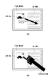
<全体の構成>
図10は、本手法を適用する表示装置3000と、それに対して指示する手段の構成を示す。図に示すように、表示装置3000は、情報を映し出す表示部3100と、操作者の指示を取得する接触感知部3200を備える。なお、表示部3100はタッチパネルであり、接触感知部3200と統合されている。さらに、図示されてはいないが、グラフィカルユーザインターフェイスの制御およびオペレーティングシステムの制御を担う制御部3300を内部に備える。そして表示装置3000を構成するものではないが、表示装置に指示を与える操作者の手である指示手段3400が図示される。
<Overall configuration>
FIG. 10 shows a configuration of a display device 3000 to which the present technique is applied and means for instructing the display device 3000. As shown in the figure, the display device 3000 includes a display unit 3100 that displays information and a contact sensing unit 3200 that acquires an instruction from the operator. Note that the display unit 3100 is a touch panel and is integrated with the contact sensing unit 3200. Further, although not shown in the figure, a control unit 3300 for controlling the graphical user interface and the operating system is provided inside. Although not constituting the display device 3000, an instruction means 3400 which is an operator's hand giving an instruction to the display device is illustrated.
<表示装置3000>
表示装置3000は、表示装置3000は操作者が手に持って携帯できる程度の大きさであり、典型的には手のひら程度の大きさ、つまり10数センチメートル四方に収まることが望ましい。操作者は表示装置3000を手に取り、もう片方の手で操作を行う。操作者の視点と表示装置3000の間の距離は典型的には数十センチメートルとなり、また基本的には表示装置3000を持つ人物以外に表示装置3000を見る人物は稀であると想定してよい。典型的なパーソナルコンピュータが備えるポインティングデバイスとしてのマウスと、文字入力デバイスとしてのキーボードを備えない。操作者は指示手段3400を動かし、タッチパネルである表示部3100に触れることでポインティング操作を入力することでマウスの機能を代替する。操作者がキーボードの代替として文字を入力する方法としては実施例1と同様に、表示部1100に従来のキーボードと同じ映像を表示し、操作者がその映像に対してキーを打つジェスチャ操作をすることで文字を入力可能にすることが挙げられる。また別の方法としては、操作者が入力する文字を声にして発し、表示装置1000がそれを認識して文字に変換する方法もある。
<Display device 3000>
The display device 3000 has a size that allows the operator to carry the display device 3000 in his / her hand. Typically, the display device 3000 is preferably about the size of a palm, that is, within a few tens of centimeters. The operator picks up the display device 3000 and operates with the other hand. The distance between the operator's viewpoint and the display device 3000 is typically several tens of centimeters, and basically, it is assumed that a person who views the display device 3000 is rare in addition to the person having the display device 3000. Good. A mouse as a pointing device and a keyboard as a character input device provided in a typical personal computer are not provided. The operator moves the instruction means 3400 and touches the display unit 3100 which is a touch panel to input a pointing operation, thereby substituting the mouse function. As a method for the operator to input characters as an alternative to the keyboard, the same video as the conventional keyboard is displayed on the
<表示部3100および接触感知部3200>
表示部3100は典型的には、2次元画像を表示できる平面的な形状の液晶ディスプレイである。画像を提示できる装置であれば液晶ディスプレイに限定しないが、例えばCRTモニタを用いては持ち運びできることを実現することは難しい。表示部3100は操作者に視覚情報を提示する装置であるが、接触感知部3200と統合されることで操作者の操作を受け付ける装置でもある。具体的には、透明な薄膜で構成される接触感知部3200を、表示部3100にはりつけることでふたつの装置を統合することができる。なお、タッチパネルの方式については公知のものを用いればよく、前記紹介した技術のうちひとつを用いることが望ましい。接触感知部3200は指示手段3400が表示部3100および接触感知部3200に触れたことを感知し、その位置が表示部3100の上のどこであるのかという位置情報を得る。
<Display unit 3100 and contact sensing unit 3200>
The display unit 3100 is typically a planar liquid crystal display capable of displaying a two-dimensional image. Any device capable of presenting an image is not limited to a liquid crystal display, but it is difficult to realize that it can be carried using, for example, a CRT monitor. The display unit 3100 is a device that presents visual information to the operator, but is also a device that accepts the operation of the operator by being integrated with the contact sensing unit 3200. Specifically, the two devices can be integrated by attaching a contact sensing unit 3200 formed of a transparent thin film to the display unit 3100. Note that a known touch panel method may be used, and it is desirable to use one of the introduced techniques. The contact sensing unit 3200 senses that the instruction unit 3400 touches the display unit 3100 and the contact sensing unit 3200, and obtains position information indicating where the position is on the display unit 3100.
<指示手段3400>
指示手段3400は、典型的には表示装置3000を操作する操作者の指である。ただし人間の指に限ったものではなく、タッチパネルに触れて位置を指定できるものであれば限定しない。例えば、ペン状の指示器具を手に持ってタッチパネルに触れるような実施例も考えられる。
<Instruction means 3400>
The instruction unit 3400 is typically an operator's finger that operates the display device 3000. However, the present invention is not limited to a human finger and is not limited as long as the position can be specified by touching the touch panel. For example, an embodiment in which a pen-shaped pointing device is held in the hand and touches the touch panel is also conceivable.
<全体の流れ>
図11は、表示装置3000が、操作者の操作により生まれる死角領域を検出し、表示部3100の表示内容を制御する全体の流れを示すフローチャートである。実施例1の全体フローを示す図2と共通の部分もあるため、その部分は割愛する。本実施例において、この図11に示す処理は全て接触感知部3200を通して得た情報を処理することにより行い、その処理は全て制御部3300が行う。
<Overall flow>
FIG. 11 is a flowchart illustrating an overall flow in which the display device 3000 detects a blind spot region generated by an operation of the operator and controls the display content of the display unit 3100. Since there is a common part with FIG. 2 which shows the whole flow of Example 1, the part is omitted. In this embodiment, all the processing shown in FIG. 11 is performed by processing information obtained through the contact sensing unit 3200, and all the processing is performed by the control unit 3300.
まず初めに制御部3300は、接触感知部3200は指示手段3400が表示部3100上に触れている位置を検出する(STEP310)。指示手段3400の接触が検出された場合(STEP320でイエス)には、指示手段3400が表示部3100を覆い隠す死角領域を検出する(STEP330)。なお、(STEP320)でノーであった場合には、死角領域を検出せずに、グラフィカルユーザインターフェイス上の項目の表示方法を制御する処理に移る(STEP340)。この(STEP330)については具体的に説明する。(STEP340)の処理については、実施例1と同一の方法を用いることができるので割愛する。図11に示した一連のフロー(STEP310)から(STEP340)は実施例1と同じように、典型的にはごく短時間で終了し1秒間の間に数十回絶えず繰り返し実行されることが望ましい。 First, the control unit 3300 detects a position where the touch sensing unit 3200 is touching the display unit 3100 on the display unit 3100 (STEP 310). When contact with the instruction unit 3400 is detected (YES in STEP 320), the instruction unit 3400 detects a blind spot area that covers the display unit 3100 (STEP 330). If no in (STEP 320), the process moves to a process for controlling the display method of items on the graphical user interface without detecting the blind spot area (STEP 340). This (STEP 330) will be specifically described. The processing in (STEP 340) is omitted because the same method as in the first embodiment can be used. As in the first embodiment, the series of flows (STEP 310) to (STEP 340) shown in FIG. 11 are typically completed in a very short time, and are preferably repeatedly executed several tens of times in one second. .
<死角領域の検出処理>
図11のフロー中の(STEP330)で示した死角領域の検出処理について説明する。実施例1では、表示部1100と指示手段1400と操作者あるいは閲覧者の視点が、3次元空間上である程度の距離と自由度を持って存在している。そのため死角領域を検出するには、表示部1100と指示手段1400と操作者あるいは閲覧者の視点の位置関係を精密に検出する必要があった。本実施例では、指示手段3400の3次元空間上の位置と、視点の3次元空間上の位置を検出せず、死角領域を求める。その理由は表示部3100と指示手段3400と操作者の視点の相対的な位置関係が3つの制約を持っているからである。
<Detection process of blind spot area>
The blind spot area detection process indicated by (STEP 330) in the flow of FIG. 11 will be described. In the first embodiment, the
まず1つに、表示部3100と指示手段3400の位置関係である。このふたつは数センチメートルのきわめて近い距離にある。それは図10に示すように、指示手段3400がタッチパネルを操作する時に表示部3100に触れるためである。また指示手段3400は、操作者の利き手が右であれば表示部3100の右下から、利き手が左であれば表示部3100の左下から表示部3100の上に向かって伸びている。 First, the positional relationship between the display unit 3100 and the instruction unit 3400 is shown. The two are very close to a few centimeters. As shown in FIG. 10, the instruction means 3400 touches the display unit 3100 when operating the touch panel. Further, the instruction unit 3400 extends from the lower right of the display unit 3100 when the operator's dominant hand is right, and from the lower left of the display unit 3100 toward the upper side of the display unit 3100 when the dominant hand is left.
さらに典型的には、操作者は表示装置3000を手に持ち、顔の正面に据えて操作する姿勢が負担のない楽な姿勢であるといえる。また表示部3100が表示する文字や画像の方向から、操作者が表示装置3000のどの辺を上にして手に持つかも限定できる。もう1つの制約として、操作者の視点と表示部3100の位置関係である。これは典型的には数十センチメートルの距離である。この表示装置3000の操作方法がタッチパネルである以上、指示手段3400、つまり手と腕あるいは指示器具の長さ以上には2つは離れることができない。3つ目の制約として、表示部3100の面積が小さく、操作者が手に持って扱うことから、複数の人間が表示装置3000を見ることは少ないといえる。つまり、操作者のみの視点が存在すると限定することができる。 More typically, the operator can hold the display device 3000 in his / her hand and put it in front of his / her face for an easy posture with no burden. In addition, it is possible to limit which side of the display device 3000 the hand is held by the operator from the direction of characters and images displayed on the display unit 3100. Another constraint is the positional relationship between the operator's viewpoint and the display unit 3100. This is typically a distance of a few tens of centimeters. As long as the operation method of the display device 3000 is a touch panel, the two cannot be separated beyond the length of the pointing means 3400, that is, the length of the hand and arm or the pointing device. As a third restriction, since the area of the display unit 3100 is small and the operator holds it in his hand, it can be said that a plurality of people rarely see the display device 3000. That is, it can be limited that there is a viewpoint only for the operator.
以上の3つの制約から、本実施例では表示部3100と指示手段3400と視点の位置関係がほぼ一定の位置関係にあると仮定し、接触感知部3200のみで得た情報に基づいて操作者にとっての死角領域の検出を近似的に行う。 Because of the above three restrictions, in this embodiment, it is assumed that the positional relationship between the display unit 3100, the instruction unit 3400, and the viewpoint is substantially constant, and the operator can use the information obtained only by the touch sensing unit 3200. The blind spot area is detected approximately.
図12は、操作者の視点から見た表示部3100と、指示手段3400と、表示部3100上に推定された死角領域を示している。ここで説明する処理では具体的には、操作者の利き手と、接触感知部3200から得られた位置情報から、死角領域を一意に求める。得られる情報は指示手段3400の先端の位置のみであり、指示手段3400の具体的な形状は得られない。そこで厳密な死角領域の形状の代わりに、例えば指示手段3400の先端の位置に基づいて楕円形の領域を設定し、それを死角領域として設定するなどがよい。楕円の大きさや形は一定ではなく、表示部3100上の位置によって動的に変えることもまたよい。また操作者の利き手がどちらかであるかは推定できないので、事前に操作者から収集しておくことがよい。 FIG. 12 shows a display unit 3100, an instruction unit 3400, and a blind spot area estimated on the display unit 3100 as viewed from the operator's viewpoint. Specifically, in the processing described here, the blind spot area is uniquely obtained from the dominant hand of the operator and the position information obtained from the contact sensing unit 3200. The obtained information is only the position of the tip of the instruction means 3400, and the specific shape of the instruction means 3400 cannot be obtained. Therefore, instead of the exact shape of the blind spot area, for example, an elliptical area may be set based on the position of the tip of the instruction means 3400 and set as the blind spot area. The size and shape of the ellipse are not constant, and may be dynamically changed depending on the position on the display portion 3100. Moreover, since it cannot be estimated whether the operator's dominant hand is either, it is good to collect from an operator beforehand.
以上実施例3で説明したように、表示画面の前面に備わったタッチパネルに対してタッチすることにより操作する表示装置において、操作によってディスプレイ上に死角領域が生れても操作や閲覧の妨げにならない表示を可能とする。 As described above in the third embodiment, in a display device that is operated by touching the touch panel provided on the front surface of the display screen, a display that does not interfere with operation or browsing even if a blind spot area is created on the display by the operation. Is possible.
(その他の実施例)
また、本発明の目的は、以下のようにすることによって達成されることはいうまでもない。即ち、前述した実施形態の機能を実現するソフトウェアのプログラムコード(コンピュータプログラム)を記録した記録媒体(または記憶媒体)を、システムあるいは装置に供給する。係る記憶媒体は言うまでもなく、コンピュータ読み取り可能な記憶媒体である。そして、そのシステムあるいは装置のコンピュータ(またはCPUやMPU)が記録媒体に格納されたプログラムコードを読み出し実行する。この場合、記録媒体から読み出されたプログラムコード自体が前述した実施形態の機能を実現することになり、そのプログラムコードを記録した記録媒体は本発明を構成することになる。
(Other examples)
Needless to say, the object of the present invention can be achieved as follows. That is, a recording medium (or storage medium) that records a program code (computer program) of software that implements the functions of the above-described embodiments is supplied to the system or apparatus. Needless to say, such a storage medium is a computer-readable storage medium. Then, the computer (or CPU or MPU) of the system or apparatus reads and executes the program code stored in the recording medium. In this case, the program code itself read from the recording medium realizes the functions of the above-described embodiment, and the recording medium on which the program code is recorded constitutes the present invention.
また、コンピュータが読み出したプログラムコードを実行することにより、そのプログラムコードの指示に基づき、コンピュータ上で稼働しているオペレーティングシステム(OS)などが実際の処理の一部または全部を行う。その処理によって前述した実施形態の機能が実現される場合も含まれることは言うまでもない。 Further, by executing the program code read by the computer, an operating system (OS) or the like running on the computer performs part or all of the actual processing based on the instruction of the program code. Needless to say, the process includes the case where the functions of the above-described embodiments are realized.
さらに、記録媒体から読み出されたプログラムコードが、コンピュータに挿入された機能拡張カードやコンピュータに接続された機能拡張ユニットに備わるメモリに書込まれたとする。その後、そのプログラムコードの指示に基づき、その機能拡張カードや機能拡張ユニットに備わるCPUなどが実際の処理の一部または全部を行い、その処理によって前述した実施形態の機能が実現される場合も含まれることは言うまでもない。 Furthermore, it is assumed that the program code read from the recording medium is written in a memory provided in a function expansion card inserted into the computer or a function expansion unit connected to the computer. After that, based on the instruction of the program code, the CPU included in the function expansion card or function expansion unit performs part or all of the actual processing, and the function of the above-described embodiment is realized by the processing. Needless to say.
本発明を上記記録媒体に適用する場合、その記録媒体には、先に説明したフローチャートに対応するプログラムコードが格納されることになる。 When the present invention is applied to the recording medium, program code corresponding to the flowchart described above is stored in the recording medium.
1000 表示装置
1100 表示部
1200 撮像部
1300 制御部
1400 指示手段
DESCRIPTION OF SYMBOLS 1000
Claims (13)
前記表示画面に前記項目を表示する表示手段と、
前記指示手段によって前記表示画面の隠れてしまう死角領域を検出する検出手段と、
前記検出手段で検出された死角領域と、前記表示手段で表示された項目の位置関係から前記表示手段で表示された項目の表示を変更して表示する変更手段と
を備えることを特徴とする表示装置。 A display device for instructing an item on a display screen by an instruction means on the front surface of the display screen,
Display means for displaying the items on the display screen;
Detecting means for detecting a blind spot area where the display screen is hidden by the instruction means;
A display comprising: a blind spot area detected by the detecting means; and a changing means for changing the display of the item displayed by the display means from the positional relationship of the items displayed by the display means. apparatus.
前記検出手段は、前記視点位置検出手段によって検出された視点の位置から前記指示手段が死角になる領域を検出することを特徴とする請求項1〜4のいずれか1項に記載の表示装置。 Further comprising a viewpoint position detecting means,
5. The display device according to claim 1, wherein the detection unit detects a region where the instruction unit becomes a blind spot from a viewpoint position detected by the viewpoint position detection unit.
前記視点位置検出手段によって複数の視点を検出された場合、複数の視点の中から優先する視点を選択する選択手段を更に有する請求項1〜5のいずれか1項に記載の表示装置。 The viewpoint position detecting means detects positions of a plurality of viewpoints;
The display device according to claim 1, further comprising a selection unit that selects a priority viewpoint from the plurality of viewpoints when a plurality of viewpoints are detected by the viewpoint position detection unit.
該復元手段は、前記変更手段によって表示画面が変更された後に、前記死角領域から前記項目が出た場合、前記変更手段によって表示される前の表示画面に復元するよう表示を制御することを特徴とする請求項1〜4のいずれか1項に記載の表示装置。 It further has a restoration means,
The restoration means controls the display to restore the display screen before being displayed by the changing means when the item comes out from the blind spot area after the changing means has changed the display screen. The display device according to any one of claims 1 to 4.
前記表示画面に前記項目を表示手段が表示する表示工程と、
前記指示手段によって前記表示画面の隠れてしまう死角領域を検出手段が検出する検出工程と、
前記検出手段で検出された死角領域と、前記表示工程で表示された項目の位置関係から前記表示画面を変更手段が変更して表示する変更工程と
を備えることを特徴とする表示装置の制御方法。 A control method of a display device that gives an instruction by an instruction means for an item on the display screen in front of the display screen,
A display step of displaying the item on the display screen;
A detection step in which the detection means detects a blind spot area where the display screen is hidden by the instruction means;
A display device control method comprising: a blind spot area detected by the detecting means; and a changing step in which the changing means changes and displays the display screen based on a positional relationship between items displayed in the display step. .
Priority Applications (1)
| Application Number | Priority Date | Filing Date | Title |
|---|---|---|---|
| JP2010176421A JP2012038025A (en) | 2010-08-05 | 2010-08-05 | Display device, control method for display device, and program |
Applications Claiming Priority (1)
| Application Number | Priority Date | Filing Date | Title |
|---|---|---|---|
| JP2010176421A JP2012038025A (en) | 2010-08-05 | 2010-08-05 | Display device, control method for display device, and program |
Publications (1)
| Publication Number | Publication Date |
|---|---|
| JP2012038025A true JP2012038025A (en) | 2012-02-23 |
Family
ID=45849981
Family Applications (1)
| Application Number | Title | Priority Date | Filing Date |
|---|---|---|---|
| JP2010176421A Pending JP2012038025A (en) | 2010-08-05 | 2010-08-05 | Display device, control method for display device, and program |
Country Status (1)
| Country | Link |
|---|---|
| JP (1) | JP2012038025A (en) |
Cited By (5)
| Publication number | Priority date | Publication date | Assignee | Title |
|---|---|---|---|---|
| JP2013182543A (en) * | 2012-03-04 | 2013-09-12 | Alpine Electronics Inc | Enlargement-reduction operation scale display method and device |
| JP2015149036A (en) * | 2014-02-10 | 2015-08-20 | レノボ・シンガポール・プライベート・リミテッド | Method of improving accuracy of operation on touch screen, electronic device, and computer program |
| JP2018004493A (en) * | 2016-07-04 | 2018-01-11 | 株式会社デンソー | Vehicle-purpose display device |
| WO2018092627A1 (en) * | 2016-11-21 | 2018-05-24 | セイコーエプソン株式会社 | Projector system |
| JP2018124847A (en) * | 2017-02-02 | 2018-08-09 | コニカミノルタ株式会社 | Image processing apparatus, condition display method, and computer program |
-
2010
- 2010-08-05 JP JP2010176421A patent/JP2012038025A/en active Pending
Cited By (9)
| Publication number | Priority date | Publication date | Assignee | Title |
|---|---|---|---|---|
| JP2013182543A (en) * | 2012-03-04 | 2013-09-12 | Alpine Electronics Inc | Enlargement-reduction operation scale display method and device |
| US9323437B2 (en) | 2012-03-04 | 2016-04-26 | Alpine Electronics, Inc. | Method for displaying scale for enlargement and reduction operation, and device therefor |
| JP2015149036A (en) * | 2014-02-10 | 2015-08-20 | レノボ・シンガポール・プライベート・リミテッド | Method of improving accuracy of operation on touch screen, electronic device, and computer program |
| JP2018004493A (en) * | 2016-07-04 | 2018-01-11 | 株式会社デンソー | Vehicle-purpose display device |
| WO2018092627A1 (en) * | 2016-11-21 | 2018-05-24 | セイコーエプソン株式会社 | Projector system |
| JP2018085552A (en) * | 2016-11-21 | 2018-05-31 | セイコーエプソン株式会社 | Projector system |
| CN109983764A (en) * | 2016-11-21 | 2019-07-05 | 精工爱普生株式会社 | Projecting apparatus system |
| US10754474B2 (en) | 2016-11-21 | 2020-08-25 | Seiko Epson Corporation | Projector system |
| JP2018124847A (en) * | 2017-02-02 | 2018-08-09 | コニカミノルタ株式会社 | Image processing apparatus, condition display method, and computer program |
Similar Documents
| Publication | Publication Date | Title |
|---|---|---|
| US11567578B2 (en) | Systems and methods of free-space gestural interaction | |
| US12032746B2 (en) | Systems and methods of creating a realistic displacement of a virtual object in virtual reality/augmented reality environments | |
| US20230333662A1 (en) | Velocity field interaction for free space gesture interface and control | |
| US9939914B2 (en) | System and method for combining three-dimensional tracking with a three-dimensional display for a user interface | |
| US10606442B2 (en) | Touch-free gesture recognition system and method | |
| CN109564472B (en) | Method, medium, and system for selecting an interaction method with a virtual object | |
| US9767613B1 (en) | Systems and method of interacting with a virtual object | |
| EP3227760B1 (en) | Pointer projection for natural user input | |
| US9671869B2 (en) | Systems and methods of direct pointing detection for interaction with a digital device | |
| US11360551B2 (en) | Method for displaying user interface of head-mounted display device | |
| JP2019087279A (en) | Systems and methods of direct pointing detection for interaction with digital device | |
| US20140157206A1 (en) | Mobile device providing 3d interface and gesture controlling method thereof | |
| US20140068476A1 (en) | Icon operating device | |
| KR101892735B1 (en) | Apparatus and Method for Intuitive Interaction | |
| CN111161396B (en) | Virtual content control method, device, terminal equipment and storage medium | |
| US11520409B2 (en) | Head mounted display device and operating method thereof | |
| US20230342024A1 (en) | Systems and Methods of Interacting with a Virtual Grid in a Three-dimensional (3D) Sensory Space | |
| JP2012038025A (en) | Display device, control method for display device, and program | |
| JP2013125985A (en) | Display system | |
| KR20200120467A (en) | Head mounted display apparatus and operating method thereof | |
| WO2022208612A1 (en) | Wearable terminal device, program and display method | |
| KR101560474B1 (en) | Apparatus and method for providing 3d user interface using stereoscopic image display device | |
| KR101455745B1 (en) | Binocular Cursor: Enabling Selection on Transparent Displays Troubled by Binocular Parallax | |
| WO2023246381A1 (en) | Interaction method and apparatus for light field display, and light field display system |