JP2011511709A - Method, system and apparatus for water treatment - Google Patents
Method, system and apparatus for water treatment Download PDFInfo
- Publication number
- JP2011511709A JP2011511709A JP2010546185A JP2010546185A JP2011511709A JP 2011511709 A JP2011511709 A JP 2011511709A JP 2010546185 A JP2010546185 A JP 2010546185A JP 2010546185 A JP2010546185 A JP 2010546185A JP 2011511709 A JP2011511709 A JP 2011511709A
- Authority
- JP
- Japan
- Prior art keywords
- water
- electrode device
- electrode
- housing
- electrodes
- Prior art date
- Legal status (The legal status is an assumption and is not a legal conclusion. Google has not performed a legal analysis and makes no representation as to the accuracy of the status listed.)
- Pending
Links
- XLYOFNOQVPJJNP-UHFFFAOYSA-N water Substances O XLYOFNOQVPJJNP-UHFFFAOYSA-N 0.000 title claims abstract description 192
- 238000000034 method Methods 0.000 title claims abstract description 70
- 239000012535 impurity Substances 0.000 claims abstract description 55
- 239000001301 oxygen Substances 0.000 claims abstract description 53
- 229910052760 oxygen Inorganic materials 0.000 claims abstract description 53
- QVGXLLKOCUKJST-UHFFFAOYSA-N atomic oxygen Chemical compound [O] QVGXLLKOCUKJST-UHFFFAOYSA-N 0.000 claims abstract description 49
- 230000008569 process Effects 0.000 claims abstract description 23
- 230000005684 electric field Effects 0.000 claims abstract description 14
- 238000005868 electrolysis reaction Methods 0.000 claims abstract description 14
- UFHFLCQGNIYNRP-UHFFFAOYSA-N Hydrogen Chemical compound [H][H] UFHFLCQGNIYNRP-UHFFFAOYSA-N 0.000 claims abstract description 12
- 239000001257 hydrogen Substances 0.000 claims abstract description 12
- 229910052739 hydrogen Inorganic materials 0.000 claims abstract description 12
- 239000007789 gas Substances 0.000 claims description 64
- 230000001590 oxidative effect Effects 0.000 claims description 29
- 238000006243 chemical reaction Methods 0.000 claims description 21
- 238000009792 diffusion process Methods 0.000 claims description 21
- 239000010865 sewage Substances 0.000 claims description 18
- 239000007800 oxidant agent Substances 0.000 claims description 17
- 239000000758 substrate Substances 0.000 claims description 16
- 229920000915 polyvinyl chloride Polymers 0.000 claims description 15
- 239000004800 polyvinyl chloride Substances 0.000 claims description 15
- 238000005273 aeration Methods 0.000 claims description 12
- 241000894007 species Species 0.000 claims description 10
- 238000004065 wastewater treatment Methods 0.000 claims description 10
- 239000012530 fluid Substances 0.000 claims description 9
- MHAJPDPJQMAIIY-UHFFFAOYSA-N Hydrogen peroxide Chemical compound OO MHAJPDPJQMAIIY-UHFFFAOYSA-N 0.000 claims description 8
- 238000009825 accumulation Methods 0.000 claims description 8
- 230000006911 nucleation Effects 0.000 claims description 8
- 238000010899 nucleation Methods 0.000 claims description 8
- 239000000463 material Substances 0.000 claims description 6
- 150000001450 anions Chemical class 0.000 claims description 5
- 150000001768 cations Chemical class 0.000 claims description 5
- 238000004891 communication Methods 0.000 claims description 5
- 229920003023 plastic Polymers 0.000 claims description 5
- 239000004033 plastic Substances 0.000 claims description 5
- 239000003642 reactive oxygen metabolite Substances 0.000 claims description 4
- 238000011144 upstream manufacturing Methods 0.000 claims description 4
- 244000052769 pathogen Species 0.000 claims description 3
- 229910001220 stainless steel Inorganic materials 0.000 claims description 3
- 239000010935 stainless steel Substances 0.000 claims description 3
- MYMOFIZGZYHOMD-UHFFFAOYSA-N Dioxygen Chemical group O=O MYMOFIZGZYHOMD-UHFFFAOYSA-N 0.000 claims description 2
- 230000029087 digestion Effects 0.000 claims description 2
- 229910001882 dioxygen Inorganic materials 0.000 claims description 2
- OUUQCZGPVNCOIJ-UHFFFAOYSA-M Superoxide Chemical compound [O-][O] OUUQCZGPVNCOIJ-UHFFFAOYSA-M 0.000 claims 1
- 239000000243 solution Substances 0.000 description 19
- 230000036647 reaction Effects 0.000 description 12
- 239000002351 wastewater Substances 0.000 description 11
- 239000012528 membrane Substances 0.000 description 7
- 238000007789 sealing Methods 0.000 description 7
- 239000000356 contaminant Substances 0.000 description 6
- 238000005086 pumping Methods 0.000 description 6
- 230000008901 benefit Effects 0.000 description 5
- 244000005700 microbiome Species 0.000 description 5
- 241001550224 Apha Species 0.000 description 4
- 230000000694 effects Effects 0.000 description 4
- 150000002500 ions Chemical class 0.000 description 4
- 235000015097 nutrients Nutrition 0.000 description 4
- ZWEHNKRNPOVVGH-UHFFFAOYSA-N 2-Butanone Chemical compound CCC(C)=O ZWEHNKRNPOVVGH-UHFFFAOYSA-N 0.000 description 3
- CSCPPACGZOOCGX-UHFFFAOYSA-N Acetone Chemical compound CC(C)=O CSCPPACGZOOCGX-UHFFFAOYSA-N 0.000 description 3
- IJGRMHOSHXDMSA-UHFFFAOYSA-N Atomic nitrogen Chemical compound N#N IJGRMHOSHXDMSA-UHFFFAOYSA-N 0.000 description 3
- LYCAIKOWRPUZTN-UHFFFAOYSA-N Ethylene glycol Chemical compound OCCO LYCAIKOWRPUZTN-UHFFFAOYSA-N 0.000 description 3
- YXFVVABEGXRONW-UHFFFAOYSA-N Toluene Chemical compound CC1=CC=CC=C1 YXFVVABEGXRONW-UHFFFAOYSA-N 0.000 description 3
- 125000000129 anionic group Chemical group 0.000 description 3
- 239000013626 chemical specie Substances 0.000 description 3
- 238000005260 corrosion Methods 0.000 description 3
- 230000007797 corrosion Effects 0.000 description 3
- 239000006185 dispersion Substances 0.000 description 3
- 229910021645 metal ion Inorganic materials 0.000 description 3
- 238000012986 modification Methods 0.000 description 3
- 230000004048 modification Effects 0.000 description 3
- 230000003647 oxidation Effects 0.000 description 3
- 238000007254 oxidation reaction Methods 0.000 description 3
- 230000029058 respiratory gaseous exchange Effects 0.000 description 3
- 150000003839 salts Chemical class 0.000 description 3
- 241000588724 Escherichia coli Species 0.000 description 2
- CTQNGGLPUBDAKN-UHFFFAOYSA-N O-Xylene Chemical compound CC1=CC=CC=C1C CTQNGGLPUBDAKN-UHFFFAOYSA-N 0.000 description 2
- 230000002378 acidificating effect Effects 0.000 description 2
- 239000007864 aqueous solution Substances 0.000 description 2
- 238000005452 bending Methods 0.000 description 2
- 238000010349 cathodic reaction Methods 0.000 description 2
- 125000002091 cationic group Chemical group 0.000 description 2
- 238000004140 cleaning Methods 0.000 description 2
- 238000011109 contamination Methods 0.000 description 2
- 230000008021 deposition Effects 0.000 description 2
- 230000033001 locomotion Effects 0.000 description 2
- 238000012423 maintenance Methods 0.000 description 2
- 230000007246 mechanism Effects 0.000 description 2
- 229910052751 metal Inorganic materials 0.000 description 2
- 239000002184 metal Substances 0.000 description 2
- 238000013508 migration Methods 0.000 description 2
- 230000005012 migration Effects 0.000 description 2
- 239000000203 mixture Substances 0.000 description 2
- BASFCYQUMIYNBI-UHFFFAOYSA-N platinum Chemical compound [Pt] BASFCYQUMIYNBI-UHFFFAOYSA-N 0.000 description 2
- 238000001556 precipitation Methods 0.000 description 2
- 230000001737 promoting effect Effects 0.000 description 2
- 239000007787 solid Substances 0.000 description 2
- 239000002904 solvent Substances 0.000 description 2
- 238000012360 testing method Methods 0.000 description 2
- 239000010409 thin film Substances 0.000 description 2
- 239000008096 xylene Substances 0.000 description 2
- 241000894006 Bacteria Species 0.000 description 1
- XDTMQSROBMDMFD-UHFFFAOYSA-N Cyclohexane Chemical compound C1CCCCC1 XDTMQSROBMDMFD-UHFFFAOYSA-N 0.000 description 1
- 241000196324 Embryophyta Species 0.000 description 1
- 239000001293 FEMA 3089 Substances 0.000 description 1
- 241001465754 Metazoa Species 0.000 description 1
- 229910002651 NO3 Inorganic materials 0.000 description 1
- NHNBFGGVMKEFGY-UHFFFAOYSA-N Nitrate Chemical compound [O-][N+]([O-])=O NHNBFGGVMKEFGY-UHFFFAOYSA-N 0.000 description 1
- CBENFWSGALASAD-UHFFFAOYSA-N Ozone Chemical compound [O-][O+]=O CBENFWSGALASAD-UHFFFAOYSA-N 0.000 description 1
- XSTXAVWGXDQKEL-UHFFFAOYSA-N Trichloroethylene Chemical group ClC=C(Cl)Cl XSTXAVWGXDQKEL-UHFFFAOYSA-N 0.000 description 1
- 241001148470 aerobic bacillus Species 0.000 description 1
- 230000001580 bacterial effect Effects 0.000 description 1
- 239000013078 crystal Substances 0.000 description 1
- 230000007423 decrease Effects 0.000 description 1
- 235000019621 digestibility Nutrition 0.000 description 1
- 239000007772 electrode material Substances 0.000 description 1
- 229910001410 inorganic ion Inorganic materials 0.000 description 1
- 229910001867 inorganic solvent Inorganic materials 0.000 description 1
- 239000003049 inorganic solvent Substances 0.000 description 1
- 238000003780 insertion Methods 0.000 description 1
- 230000037431 insertion Effects 0.000 description 1
- 238000005259 measurement Methods 0.000 description 1
- 229910000000 metal hydroxide Inorganic materials 0.000 description 1
- 150000004692 metal hydroxides Chemical class 0.000 description 1
- 229910001960 metal nitrate Inorganic materials 0.000 description 1
- 229910001463 metal phosphate Inorganic materials 0.000 description 1
- 150000002739 metals Chemical class 0.000 description 1
- 244000000010 microbial pathogen Species 0.000 description 1
- 239000008239 natural water Substances 0.000 description 1
- 150000002823 nitrates Chemical class 0.000 description 1
- 229910052757 nitrogen Inorganic materials 0.000 description 1
- 239000005416 organic matter Substances 0.000 description 1
- 239000003960 organic solvent Substances 0.000 description 1
- 230000003204 osmotic effect Effects 0.000 description 1
- 230000036284 oxygen consumption Effects 0.000 description 1
- 238000006213 oxygenation reaction Methods 0.000 description 1
- 230000000149 penetrating effect Effects 0.000 description 1
- 239000002957 persistent organic pollutant Substances 0.000 description 1
- 235000021317 phosphate Nutrition 0.000 description 1
- 150000003013 phosphoric acid derivatives Chemical class 0.000 description 1
- 229910052697 platinum Inorganic materials 0.000 description 1
- 238000012545 processing Methods 0.000 description 1
- 238000000746 purification Methods 0.000 description 1
- 238000000926 separation method Methods 0.000 description 1
- 238000005476 soldering Methods 0.000 description 1
- 238000010561 standard procedure Methods 0.000 description 1
- 239000000126 substance Substances 0.000 description 1
- 238000012546 transfer Methods 0.000 description 1
- UBOXGVDOUJQMTN-UHFFFAOYSA-N trichloroethylene Natural products ClCC(Cl)Cl UBOXGVDOUJQMTN-UHFFFAOYSA-N 0.000 description 1
- 239000000341 volatile oil Substances 0.000 description 1
- 238000003466 welding Methods 0.000 description 1
Images


Classifications
-
- C—CHEMISTRY; METALLURGY
- C02—TREATMENT OF WATER, WASTE WATER, SEWAGE, OR SLUDGE
- C02F—TREATMENT OF WATER, WASTE WATER, SEWAGE, OR SLUDGE
- C02F3/00—Biological treatment of water, waste water, or sewage
- C02F3/02—Aerobic processes
- C02F3/12—Activated sludge processes
- C02F3/20—Activated sludge processes using diffusers
- C02F3/202—Aeration by electrolytically produced oxygen bubbles
-
- B—PERFORMING OPERATIONS; TRANSPORTING
- B09—DISPOSAL OF SOLID WASTE; RECLAMATION OF CONTAMINATED SOIL
- B09C—RECLAMATION OF CONTAMINATED SOIL
- B09C1/00—Reclamation of contaminated soil
- B09C1/002—Reclamation of contaminated soil involving in-situ ground water treatment
-
- C—CHEMISTRY; METALLURGY
- C02—TREATMENT OF WATER, WASTE WATER, SEWAGE, OR SLUDGE
- C02F—TREATMENT OF WATER, WASTE WATER, SEWAGE, OR SLUDGE
- C02F1/00—Treatment of water, waste water, or sewage
- C02F1/46—Treatment of water, waste water, or sewage by electrochemical methods
- C02F1/461—Treatment of water, waste water, or sewage by electrochemical methods by electrolysis
- C02F1/467—Treatment of water, waste water, or sewage by electrochemical methods by electrolysis by electrochemical disinfection; by electrooxydation or by electroreduction
- C02F1/4672—Treatment of water, waste water, or sewage by electrochemical methods by electrolysis by electrochemical disinfection; by electrooxydation or by electroreduction by electrooxydation
-
- C—CHEMISTRY; METALLURGY
- C02—TREATMENT OF WATER, WASTE WATER, SEWAGE, OR SLUDGE
- C02F—TREATMENT OF WATER, WASTE WATER, SEWAGE, OR SLUDGE
- C02F3/00—Biological treatment of water, waste water, or sewage
- C02F3/02—Aerobic processes
- C02F3/12—Activated sludge processes
- C02F3/22—Activated sludge processes using circulation pipes
- C02F3/223—Activated sludge processes using circulation pipes using "air-lift"
-
- C—CHEMISTRY; METALLURGY
- C02—TREATMENT OF WATER, WASTE WATER, SEWAGE, OR SLUDGE
- C02F—TREATMENT OF WATER, WASTE WATER, SEWAGE, OR SLUDGE
- C02F1/00—Treatment of water, waste water, or sewage
- C02F1/46—Treatment of water, waste water, or sewage by electrochemical methods
- C02F1/461—Treatment of water, waste water, or sewage by electrochemical methods by electrolysis
- C02F1/46104—Devices therefor; Their operating or servicing
- C02F1/46109—Electrodes
- C02F2001/46152—Electrodes characterised by the shape or form
-
- C—CHEMISTRY; METALLURGY
- C02—TREATMENT OF WATER, WASTE WATER, SEWAGE, OR SLUDGE
- C02F—TREATMENT OF WATER, WASTE WATER, SEWAGE, OR SLUDGE
- C02F2103/00—Nature of the water, waste water, sewage or sludge to be treated
- C02F2103/007—Contaminated open waterways, rivers, lakes or ponds
-
- Y—GENERAL TAGGING OF NEW TECHNOLOGICAL DEVELOPMENTS; GENERAL TAGGING OF CROSS-SECTIONAL TECHNOLOGIES SPANNING OVER SEVERAL SECTIONS OF THE IPC; TECHNICAL SUBJECTS COVERED BY FORMER USPC CROSS-REFERENCE ART COLLECTIONS [XRACs] AND DIGESTS
- Y02—TECHNOLOGIES OR APPLICATIONS FOR MITIGATION OR ADAPTATION AGAINST CLIMATE CHANGE
- Y02W—CLIMATE CHANGE MITIGATION TECHNOLOGIES RELATED TO WASTEWATER TREATMENT OR WASTE MANAGEMENT
- Y02W10/00—Technologies for wastewater treatment
- Y02W10/10—Biological treatment of water, waste water, or sewage
Landscapes
- Life Sciences & Earth Sciences (AREA)
- Chemical & Material Sciences (AREA)
- Engineering & Computer Science (AREA)
- Water Supply & Treatment (AREA)
- Hydrology & Water Resources (AREA)
- Environmental & Geological Engineering (AREA)
- Organic Chemistry (AREA)
- Microbiology (AREA)
- Electrochemistry (AREA)
- Chemical Kinetics & Catalysis (AREA)
- General Chemical & Material Sciences (AREA)
- Biodiversity & Conservation Biology (AREA)
- Soil Sciences (AREA)
- Water Treatment By Electricity Or Magnetism (AREA)
- Purification Treatments By Anaerobic Or Anaerobic And Aerobic Bacteria Or Animals (AREA)
- Treatment Of Water By Oxidation Or Reduction (AREA)
- Biological Treatment Of Waste Water (AREA)
Abstract
本発明は、水を改善するための電解法を提供する。本発明の1つの態様は、有機不純物及び/又は無機不純物を中に有する水を処理するための電解法を提供する。この方法は、下記を含む。(a)少なくとも1つの第1の電極装置に水を接触させることと、(b)非物理的で電気的な態様で水と接触する少なくとも1つの第2の電極装置を設けることと、(c)第2の電極装置と第1の電極装置との間に電流を通し、水の中に次の各プロセス、即ち、(i)水から無機不純物を分離するのを助けるために、それらの集積を局所化すること、及び(ii)水を電離して、有機不純物及び/又は無機不純物を処理するための溶存酸素種及び溶存水素種を生成すること、の一方又は両方を実施するのに十分な強度及び継続時間の電界を構築すること。更に、非導電性筐体と、筐体内に配置された1つ又は複数の電極と、筐体内の入口及び出口であって、上記1つ又は複数の電極と接触するような形で不純物含有水にその筐体を通過させるための入口及び出口と、上記1つ又は複数の電極を電源装置に接続するための手段と、を具備する電極装置も提供されている。 The present invention provides an electrolysis method for improving water. One aspect of the present invention provides an electrolytic method for treating water having organic and / or inorganic impurities therein. The method includes: (A) bringing water into contact with at least one first electrode device; (b) providing at least one second electrode device in contact with water in a non-physical and electrical manner; (c) ) Passing an electric current between the second electrode device and the first electrode device to collect each of the following processes into the water: (i) separating inorganic impurities from the water And (ii) sufficient to perform one or both of ionizing water to produce dissolved oxygen species and dissolved hydrogen species to treat organic and / or inorganic impurities Build an electric field of sufficient strength and duration. In addition, the non-conductive housing, the one or more electrodes disposed in the housing, and the inlet and outlet in the housing, the impurity-containing water in contact with the one or more electrodes. There is also provided an electrode device comprising an inlet and an outlet for passing through the housing, and means for connecting the one or more electrodes to a power supply.
Description
本発明は、有機不純物及び/又は無機不純物を含有する水を処理するための方法及びシステムに関する。更に、本発明は、上記の方法及びシステムで使用する電極装置に関する。加えて、本発明は、例えば上記の方法及びシステムで使用可能なガス拡散装置に関する。 The present invention relates to a method and system for treating water containing organic and / or inorganic impurities. The invention further relates to an electrode device for use in the above method and system. In addition, the present invention relates to a gas diffusion device that can be used, for example, in the above methods and systems.
不純物含有水を処理するためのシステムは、長年の間に多種多様になってきた。水処理システムが用いられる環境は、貯水槽、池、湖、及び下水処理プラントといった大規模のものから、家庭用浄化槽システム、水槽、池、及びため池といった小規模のものまで及ぶ。これらの用途の全てにおいて、処理プロセスの目的は、植物由来物質若しくは動物由来物質、下水汚物及び病原体、といった有機汚染物質又は金属イオン、燐酸塩、及び硝酸塩を含む無機不純物を除去又は中和することである。処理によって生まれる水の良質性の尺度の例として、総懸濁物質(TSS)、生物化学的酸素要求量(BOD)、総窒素(TN)、大腸菌群数、溶存酸素(DO)、及び無機化学種の濃度が挙げられる。 Systems for treating impure water have become diverse over the years. Environments in which water treatment systems are used range from large scales such as water tanks, ponds, lakes, and sewage treatment plants to small scales such as domestic septic tank systems, water tanks, ponds, and ponds. In all of these applications, the purpose of the treatment process is to remove or neutralize organic pollutants such as plant or animal derived materials, sewage and pathogens, or inorganic impurities including metal ions, phosphates, and nitrates. It is. Examples of quality measures of water produced by treatment include total suspended matter (TSS), biochemical oxygen demand (BOD), total nitrogen (TN), coliform count, dissolved oxygen (DO), and inorganic chemistry The concentration of the species.
下水処理の場合、下水の処理で以前に用いられていたシステムは、簡単で純粋に嫌気性の浄化槽から、複数のフィルタ層を組み込んだ複雑なフィルタシステムまで及んでいた。このフィルタシステムでは、嫌気性バクテリアの活動及び好気性バクテリアの活動はどちらも、栄養分の摂取と汚染物質の除去を連続的に行い、水をより純粋な形で残すことができる。 In the case of sewage treatment, the systems previously used in sewage treatment ranged from simple, purely anaerobic septic tanks to complex filter systems incorporating multiple filter layers. In this filter system, both anaerobic and aerobic bacterial activity can continuously ingest nutrients and remove contaminants, leaving water in a purer form.
浸透放水路の分散フィールドシステムに放出される排出物の水準が、水質の尺度として慣行的に用いられる全有害品質項目、即ちTSS、BOD、総窒素、及び大腸菌群数、で極めて高いことが、多くの場合、上記の簡単な浄化槽の共通した特徴である。 The level of effluent released into the distributed field system of an osmotic canal is very high in all harmful quality items customarily used as a measure of water quality, namely TSS, BOD, total nitrogen, and number of coliforms, In many cases, this is a common feature of the simple septic tank described above.
更に、これらのパラメータの実測値が地方当局の最大許容レベルを超えることが、多くの場合、上記の複雑な方の汚水処理システムの共通した特徴である。 Furthermore, it is often a common feature of the above complex sewage treatment systems that the measured values of these parameters exceed the maximum allowable level of the local authorities.
最大許容カウント数より低いカウント数をいつも達成するシステムは、多くの場合、設置するのに費用がかかる上に、システムの耐用年数全体にわたって、厳格且つ高価な保守体制を必要とする。 Systems that always achieve counts below the maximum allowable count are often expensive to install and require rigorous and expensive maintenance throughout the life of the system.
無機汚染物質を除去するシステムは、典型的には有機物を除去するシステムとは全く異なり、通常、熱技術、膜技術、又は電解技術を要する。これらも多くの場合複雑であり、大量のエネルギー量に対する出費及び高い保守費用を伴う。 Systems that remove inorganic contaminants are typically quite different from systems that remove organic matter and typically require thermal, membrane, or electrolysis techniques. These are also often complex, with high energy costs and high maintenance costs.
更に、有機不純物及び無機不純物を共に除去することは、単一の方法又はシステムを使うことでは通常は実施することができず、このため、両方のタイプの不純物を含有する水の処理は複雑になる。 Furthermore, removing both organic and inorganic impurities cannot usually be performed using a single method or system, which complicates the treatment of water containing both types of impurities. Become.
したがって、本発明の目的は、従来技術の1つ又は複数の難点を解決又は少なくとも軽減する、不純物含有水の処理方法を提供することである。 Accordingly, it is an object of the present invention to provide a method for treating impurity-containing water that solves or at least alleviates one or more difficulties of the prior art.
本発明によれば、有機不純物及び/又は無機不純物を中に有する水を処理するための電解法が提供される。この方法は下記を含む。
(a)少なくとも1つの第1の電極装置に水を接触させることと、
(b)非物理的で電気的な態様で上記水と接触する少なくとも1つの第2の電極装置を設けることと、
(c)上記第2の電極装置と上記第1の電極装置との間に電流を通し、上記水の中に次のプロセスの一方又は両方を実施するのに十分な強度及び継続時間の電界を構築すること。
(i)水から無機不純物を分離するのを助けるために、それらの集積を局所化すること。
(ii)水を電離して、有機不純物及び/又は無機不純物を処理するための溶存酸素種及び溶存水素種を生成すること。
According to the present invention, there is provided an electrolysis method for treating water having organic impurities and / or inorganic impurities therein. This method includes:
(A) bringing water into contact with at least one first electrode device;
(B) providing at least one second electrode device in contact with the water in a non-physical and electrical manner;
(C) passing an electric current between the second electrode device and the first electrode device to generate an electric field of sufficient strength and duration in the water to perform one or both of the following processes: To build.
(I) localizing their accumulation to help separate inorganic impurities from water.
(Ii) ionizing water to produce dissolved oxygen species and dissolved hydrogen species for treating organic and / or inorganic impurities;
上記の方法は、本明細書に記載の電極装置の内のいずれかを使用することを含むことができる。 The above method can include using any of the electrode devices described herein.
更に、本発明は、前段の方法で使用する電極装置も提供する。この電極装置は下記を具備する。
非導電性筐体と、
上記筐体内に配置された1つ又は複数の電極と、
上記筐体内の入口及び出口であって、上記1つ又は複数の電極と接触するような形で不純物含有水にその筐体を通過させるための入口及び出口と、
上記1つ又は複数の電極を電源装置に接続するための手段。
Furthermore, the present invention also provides an electrode device for use in the previous method. This electrode device comprises:
A non-conductive housing;
One or more electrodes disposed in the housing;
An inlet and outlet in the housing for allowing the water containing impurities to pass through the housing in contact with the one or more electrodes;
Means for connecting the one or more electrodes to a power supply;
本発明は更に、有機不純物及び/又は無機不純物を中に有する水を処理するための電解法で使用するシステムを提供する。このシステムは下記を具備する。
(a)水と接触する少なくとも1つの第1の電極装置と、
(b)非物理的で電気的な態様で上記水と接触する少なくとも1つの第2の電極装置と、
(c)上記第1及び第2の電極装置と電気的に接続し、上記水の中に次のプロセスの一方又は両方を実施するのに十分な強度及び継続時間の電界を構築する電源装置。
(i)水から無機不純物を分離するのを助けるために、それらの集積を局所化すること。
(ii)水を電離して、有機不純物及び/又は無機不純物を処理するための溶存酸素種及び溶存水素種を生成すること。
The present invention further provides a system for use in an electrolytic process for treating water having organic and / or inorganic impurities therein. This system comprises:
(A) at least one first electrode device in contact with water;
(B) at least one second electrode device in contact with the water in a non-physical and electrical manner;
(C) A power supply that is electrically connected to the first and second electrode devices and builds an electric field of sufficient strength and duration to perform one or both of the following processes in the water.
(I) localizing their accumulation to help separate inorganic impurities from water.
(Ii) ionizing water to produce dissolved oxygen species and dissolved hydrogen species for treating organic and / or inorganic impurities;
システムは、本明細書に開示の電極装置の内のいずれかを使用することを含むことができる。 The system can include using any of the electrode devices disclosed herein.
本発明は更に、下記を具備するガス拡散装置を提供する。
ガスを含有する水流を通すための入口及び出口を具備している拡散器筐体と、
上記拡散器筐体内の1つ又は複数の基体であって、上記ガスのマイクロバブルを形成するための核形成部位を提供するように構成され且つ配設された1つ又は複数の基体。
The present invention further provides a gas diffusion device comprising:
A diffuser housing having an inlet and an outlet for passing a water stream containing gas;
One or more substrates within the diffuser housing, the one or more substrates configured and arranged to provide a nucleation site for forming microbubbles of the gas.
本明細書で説明しているように、かかるガス拡散装置は、例えば電解法又は電解システムと一緒に使用することができる。 As described herein, such gas diffusion devices can be used with, for example, electrolysis or electrolysis systems.
したがって、本発明は、水に電解処理を施して有機不純物及び無機不純物を除去するための方法、システム、及び装置を提供するものである。この水は、任意の適切な環境から出てきたもので構わず、静止していてもよければ運動していてもよい。例えば、水は、水盤、水槽、池、湖、貯水槽、又は廃水処理システムに収容されている汚水の水塊から得られるものでもよければ、川又はパイプラインの水の如く動いている水から得られるものでもよい。この水は、通常は水収容手段の中に収容される。 Accordingly, the present invention provides a method, system, and apparatus for subjecting water to electrolytic treatment to remove organic and inorganic impurities. This water may come from any suitable environment and may be stationary or exercising. For example, the water can be from a basin, aquarium, pond, lake, water tank, or sewage water mass contained in a wastewater treatment system, or from water that is moving like water in a river or pipeline. It may be obtained. This water is usually stored in water storage means.
本明細書では、「水」という用語は、任意の水溶液又は部分的水溶液を含むように意図されている。部分的水溶液は、トルエン、キシレン、メチルエチルケトン、シクロヘキサン、アセトン、エチレングリコール、トリクロロエチレン、テレビン油、揮発油、及びキシレンといった有機溶剤及び無機溶剤、等の水以外の溶剤を含むことができる。以下の説明では、下水処理システムで行われているような廃水の処理に焦点を合わせることにする。但し、本発明は上記の用途に限定されないのであり、このことは理解されている必要がある。 As used herein, the term “water” is intended to include any aqueous or partial aqueous solution. Partial aqueous solutions can include solvents other than water, such as toluene, xylene, methyl ethyl ketone, cyclohexane, acetone, ethylene glycol, trichloroethylene, turpentine oil, volatile oil, and organic and inorganic solvents such as xylene. In the following description, we will focus on the treatment of wastewater as is done in sewage treatment systems. However, the present invention is not limited to the above applications, and this needs to be understood.
この方法とシステムは共に、第1の電極装置及び第2の電極装置を使用することを含む。第1の電極装置は、直接物理的に且つ電気的に水と接触しており、通常は陰極性である。そのため、それは通常、使用時に負の帯電を呈する。この第1の電極装置又は各第1の電極装置は、非導電性筐体を具備するとともに、その中に電極を具備し、この電極と接触するような形で水を流すための導管をこの筐体が提供していることが好ましい。別の実施形態において、第1の電極装置は、水に浸漬された電極メッシュ又は電極プレートにより構成することが可能である。 Both the method and system include using a first electrode device and a second electrode device. The first electrode device is in direct physical and electrical contact with water and is usually cathodic. Therefore, it usually exhibits a negative charge during use. The first electrode device or each first electrode device has a non-conductive housing, and has an electrode therein, and a conduit for flowing water in contact with the electrode. The housing is preferably provided. In another embodiment, the first electrode device can be composed of an electrode mesh or electrode plate immersed in water.
第2の電極装置は、水と電気的に接触しているが物理的には接触しておらず、通常は陽極性である。そのため、それは通常、使用時に正の帯電を呈する。第2の電極装置は大地と接触するのがよく、水から遠く離れて接地棒を備えていることが好ましい。別の実施形態において、第2の電極装置は、水を保持する収容手段の壁の少なくとも一部を構成していてもよい。 The second electrode device is in electrical contact with water but not in physical contact and is usually anodic. As such, it usually exhibits a positive charge during use. The second electrode device should be in contact with the ground, and is preferably provided with a ground bar far from the water. In another embodiment, the second electrode device may constitute at least a part of the wall of the storage means for holding water.
したがって、第2の電極装置は、水とは電気的に接触しているものの、物理的には直接接触していない。上記は、(例えば、湖又は下水処理プラントなど、大きな水塊を室外で処理する場合に)第2の電極装置を水塊から離して大地に埋めることによって実施される。或いは、(例えば、水槽又は池など、小さな水塊が処理される場合に)電極は、水塊を保持する収容手段の外壁により構成することが可能である。いずれにせよ、水と第2の電極装置との間に電気的接触を存在させるために、水塊を包囲する水収容手段(例えば壁、周囲の大地、等)は、導電性である必要がある。 Therefore, although the second electrode device is in electrical contact with water, it is not in direct physical contact. The above is performed by embedding the second electrode device in the ground away from the water mass (for example, when processing a large water mass outdoors such as a lake or a sewage treatment plant). Alternatively, the electrode can be constituted by the outer wall of the housing means holding the water mass (for example, when a small water mass is treated, such as a water tank or pond). In any case, in order for electrical contact to exist between the water and the second electrode device, the water containment means (eg walls, surrounding earth, etc.) surrounding the water mass must be electrically conductive. is there.
本発明の重要な特徴は、水を第2の電極装置と物理的に接触させないことによって、水の化学的性質を制御できることである。理論による制約を望むものではないが、第1の電極装置に関連する半電池反応は進行できるが、第2の電極装置に関連する半電池反応は進行できないと考えている。というのは、関連する水溶性化学種は第2の電極装置の電荷点に到達することができず、したがって、第2の電極装置に関連する半電池反応が水の中で進行して完了するにはイオンのマイグレーションの存在が不十分だからである。むしろ、第2の電極と、第2の電極と収容手段の内面との間の領域と、が半電池になる。 An important feature of the present invention is that the chemistry of the water can be controlled by not bringing the water into physical contact with the second electrode device. Without wishing to be bound by theory, it is believed that the half-cell reaction associated with the first electrode device can proceed, but the half-cell reaction associated with the second electrode device cannot proceed. This is because the associated water-soluble species cannot reach the charge point of the second electrode device, and thus the half-cell reaction associated with the second electrode device proceeds and completes in water. This is because there is insufficient ion migration. Rather, the second electrode and the region between the second electrode and the inner surface of the housing means become a half-cell.
第2の電極装置を水塊と直接物理的に接触させないことに関連する別の利点は、電極のガルバニック腐食が最小限に抑えられることである。 Another advantage associated with not having the second electrode device in direct physical contact with the water mass is that galvanic corrosion of the electrode is minimized.
前述のように、第1の電極装置が陰極性であり、第2の電極装置が陽極性であることが好ましい。 As described above, it is preferable that the first electrode device is cathodic and the second electrode device is anodic.
陰極性の第1の電極装置は、多くの理由で好適である。第1に、陽極性の第2の電極装置が水と物理的に接触していないため、通常は陽極に関連している半電池反応を完了するには、イオンマイグレーションの存在が不十分である。具体的には、気相としての酸素の生成及び溶液からの放出を伴う半電池反応は、水の電気分解中の典型的な陽極性半電池反応だということである。しかし、本発明の方法の好適な実施形態では、陽極性の第2の電極装置が水の外側に存在するために、これらの半電池反応に関与する陰イオンは、陽極性の電荷点に到達することができない。したがって、反応の結果が気相としての酸素の溶液からの放出(「ガスになって出て行く」)に帰着するには、水の中の電流の密度が不十分である。したがって、酸素は溶液中に溶解され、この溶液は、酸素でおそらく過飽和状態になっている酸素リッチな溶液に帰着する。この環境は、有機不純物を処理する際に、特に有利である。 The cathodic first electrode device is suitable for a number of reasons. First, because the anodic second electrode device is not in physical contact with water, the presence of ion migration is insufficient to complete the half-cell reaction normally associated with the anode. . Specifically, the half-cell reaction involving the generation of oxygen as a gas phase and release from solution is a typical anodic half-cell reaction during the electrolysis of water. However, in a preferred embodiment of the method of the invention, the anionic second electrode device is outside the water so that the anions involved in these half-cell reactions reach the anodic charge point. Can not do it. Thus, the density of the current in the water is insufficient for the result of the reaction to result in the release of oxygen as a gas phase from the solution (“go out as a gas”). Thus, oxygen is dissolved in the solution, which results in an oxygen-rich solution that is probably supersaturated with oxygen. This environment is particularly advantageous when treating organic impurities.
陰極性の第1の電極装置が好適であるもう一つの理由は、ほとんどの無機汚染物質が陽イオン性(とりわけ金属イオン)だということである。これは、陽イオンがカソードまで移動することになり、そこで陽イオンに半電池反応及び/又は塩としての沈殿が起こる可能性があることを意味する。この反応及び沈殿は、溶液から汚染物質を除去することができる。 Another reason that the cathodic first electrode device is preferred is that most inorganic contaminants are cationic (especially metal ions). This means that cations will migrate to the cathode, where cations may undergo half-cell reactions and / or precipitation as salts. This reaction and precipitation can remove contaminants from the solution.
更に、共通電極材料の安定性は、陽極性条件下よりも陰極性条件下の方が高い。陽極性条件下では、多くの共通電極金属は酸化(ガルバニック腐食)を受け易くなるであろう。酸化が起こると、水は陽極金属の水酸化物で一層汚れることになるであろう。したがって、第1の電極装置が陽極性である場合に、白金等の耐酸化性材料でそれを作製することが好ましい。 Furthermore, the stability of the common electrode material is higher under cathodic conditions than under anodic conditions. Under anodic conditions, many common electrode metals will be susceptible to oxidation (galvanic corrosion). When oxidation occurs, the water will become more contaminated with anode metal hydroxide. Therefore, when the first electrode device is anodic, it is preferably made of an oxidation resistant material such as platinum.
いくつかの実施形態において、電極の極性を反転することができる。例えば、第1の電極装置が陰極性であり、第2の電極装置が陽極性である場合に、電極を定期的に清浄する目的で少なくとも一時的に電極の極性を反転し、電気分解時に電極上に堆積した物質、例えば金属塩、を除去することができる。 In some embodiments, the polarity of the electrodes can be reversed. For example, when the first electrode device is cathodic and the second electrode device is anodic, the polarity of the electrode is reversed at least temporarily for the purpose of periodically cleaning the electrode, and the electrode is used during electrolysis. The material deposited thereon, such as metal salts, can be removed.
電流が電極を通過する際に、水の中に電界が構築される。この電流は、極性の反転を要する一部の用途ではAC電流が使用される場合もあるが、通常はDCである。電界は、次のプロセスの一方又は両方を実施するのに十分なだけの強度及び継続時間を有する必要がある。
(i)水から無機不純物を分離するのを助けるために、それらの集積を局所化すること。
(ii)水を電離して、有機不純物及び/又は無機不純物を処理するための溶存酸素種及び溶存水素種を生成すること。
電界の強度に影響を及ぼす要因の例として、処理される水の容積及び電極装置、特に第1の電極装置、の数量と大きさが挙げられる。
As current passes through the electrodes, an electric field is built in the water. This current is typically DC, although AC current may be used in some applications that require polarity reversal. The electric field needs to have a strength and duration sufficient to carry out one or both of the following processes.
(I) localizing their accumulation to help separate inorganic impurities from water.
(Ii) ionizing water to produce dissolved oxygen species and dissolved hydrogen species for treating organic and / or inorganic impurities;
Examples of factors that affect the strength of the electric field include the volume of water to be treated and the quantity and size of the electrode device, particularly the first electrode device.
不純物が無機物、特に金属イオン等の無機イオン、である場合に、それらを除去するメカニズムは、プロセス(i)を含む可能性が高いであろう。無機不純物の局所的集積は、溶液中のイオン性不純物がそれぞれ反対電荷の電極に移動することによって起こる。したがって、第1の電極装置が陰極性である場合に、陽イオン不純物はそこに引き寄せられる。その不純物はそこで還元され且つ/又は溶液中の陰イオン種とでおそらく塩を形成するであろう。同様に、陰イオン不純物は、水収容手段の内面に引き寄せられる。したがって、これらの無機不純物は電極及び水収容手段の内面に集積され、中間領域では不純物が比較的取り除かれた形で水が残り、その水を取り出して使用することができる。 If the impurities are inorganic, especially inorganic ions such as metal ions, the mechanism for removing them will likely include process (i). Local accumulation of inorganic impurities occurs as ionic impurities in the solution migrate to oppositely charged electrodes. Therefore, when the first electrode device is cathodic, cationic impurities are attracted thereto. The impurities will then be reduced and / or possibly form a salt with the anionic species in solution. Similarly, anionic impurities are attracted to the inner surface of the water containing means. Accordingly, these inorganic impurities are accumulated on the inner surfaces of the electrode and the water storage means, and water remains in the intermediate region in a state in which the impurities are relatively removed, and the water can be taken out and used.
電界も、通常は、上記に追加的に又は上記に代えて水の電離を起こすのに十分なだけの強度及び継続時間を有しており、プロセス(ii)に従って、水の中に溶存酸素及び溶存水素を生成する。このメカニズムは、一部の無機不純物のみならず、有機不純物の除去についても、大きく関与している。全体の反応は、下記の通りである。
2H2O(l)→2H2(g)+O2(g)
The electric field also usually has a strength and duration sufficient to cause ionization of water in addition to or instead of the above, and dissolved oxygen and water in the water according to process (ii) Generates dissolved hydrogen. This mechanism is greatly involved not only in removing some inorganic impurities but also in removing organic impurities. The overall reaction is as follows.
2H 2 O (l) → 2H 2 (g) + O 2 (g)
半電池反応は、水のpHに応じて、下記のようになっている。
アルカリ性(例えばpH=8)
陰極反応:
2H2O(l)+2e−→H2(g)+2OH−(aq)
陽極反応:
4OH−(aq)→O2(g)+2H2O(l)+4e−
酸性(例えばpH=6)
陽極反応:
2H2O(l)→O2(g)+4H+(aq)+4e−
陰極反応:
2H+(aq)+2e−→H2(g)
The half-cell reaction is as follows depending on the pH of the water.
Alkaline (for example, pH = 8)
Cathodic reaction:
2H 2 O (l) + 2e − → H 2 (g) + 2OH − (aq)
Anodic reaction:
4OH − (aq) → O 2 (g) + 2H 2 O (l) + 4e −
Acidic (for example, pH = 6)
Anodic reaction:
2H 2 O (l) → O 2 (g) + 4H + (aq) + 4e −
Cathodic reaction:
2H + (aq) + 2e − → H 2 (g)
しかし、前に述べたように、水の中で物理的に非接触状態の第2の電極装置に対する半電池反応は、完了には進まない。 However, as previously mentioned, the half-cell reaction to the second electrode device in a physically non-contact state in water does not proceed to completion.
典型的には、第2の電極装置は陽極性であろう。これは、上記陽極反応に対する水中の電流密度が不十分であり、ガス状になるには不十分な濃度で酸素が発生することを意味する。酸素はむしろ、溶液中に溶解される。溶存酸素は、好気性微生物の呼吸及び成長を速めるのを支援する。これは、有機汚染物質及び/又は無機汚染物質から成る栄養分のより迅速な生物学的消化をもたらす。汚染物質がひとたび消化されれば、溶液のBODは減少し、これらの好気性微生物は自然に死滅する。 Typically, the second electrode device will be anodic. This means that the current density in water for the anodic reaction is insufficient and oxygen is generated at a concentration insufficient to become gaseous. Rather, oxygen is dissolved in the solution. Dissolved oxygen helps accelerate the respiration and growth of aerobic microorganisms. This results in a more rapid biological digestion of nutrients consisting of organic and / or inorganic contaminants. Once the contaminants are digested, the BOD of the solution is reduced and these aerobic microorganisms die naturally.
本発明のプロセスは、汚水の悪臭を、特にこの悪臭が嫌気性微生物の呼吸に関連する場合に、有利に低減する。 The process of the present invention advantageously reduces the malodor of sewage, particularly when this malodor is associated with respiration of anaerobic microorganisms.
逆に、第2の電極装置が陰極性である場合は、陰極性半電池反応は、気相として放出されるには不十分な濃度で水素を生成し、溶液中で水素はおそらく過飽和になっているであろう。溶存水素は、溶液から硝酸塩を除去するのを支援する溶液中の水素酸化脱窒細菌(HOD)によって摂取される。 Conversely, if the second electrode device is cathodic, the cathodic half-cell reaction produces hydrogen at a concentration that is insufficient to be released as the gas phase, and hydrogen is probably supersaturated in solution. It will be. Dissolved hydrogen is taken up by hydro-oxidative denitrifying bacteria (HOD) in the solution that helps remove nitrate from the solution.
Cl2、N2といった他の気相化学種の溶液中の濃度も、これらのガスを生成する関連の半電池反応が進行可能かどうかに応じて、同様の態様で制御することができる。 The concentration of other gas phase species such as Cl 2 and N 2 in the solution can also be controlled in a similar manner depending on whether the associated half-cell reaction producing these gases can proceed.
通常は、本発明の方法の期間中に、(i)と(ii)の両方のプロセスが起こることになる。但し、水の中に存在する有機不純物及び無機不純物の相対的な量に応じて、一方が支配的になる場合がある。 Normally, both processes (i) and (ii) will occur during the method of the present invention. However, depending on the relative amounts of organic and inorganic impurities present in the water, one may become dominant.
更に、本発明は、本発明の電解法及びシステムで使用できる電極装置も提供する。この電極装置は、本発明の方法における第1の電極装置としての、即ち、処理される水と接触するような形での、使用が意図されていることが好ましい。電極装置は、非導電性筐体と、この筐体内に配置された1つ又は複数の電極と、を具備する。この筐体は、好ましくはプラスチック材料、より好ましくはポリ塩化ビニル、で作製された1つ又は複数の管体を具備することが好ましい。筐体は、好ましくは穿孔がなく、実質的に中実の壁を有する。このような壁は、電極の汚染を最小限に抑えるという利点を有する。 Furthermore, the present invention also provides an electrode device that can be used in the electrolysis method and system of the present invention. This electrode device is preferably intended for use as the first electrode device in the method of the invention, i.e. in contact with the water to be treated. The electrode device includes a non-conductive housing and one or more electrodes disposed in the housing. The housing preferably comprises one or more tubes made of a plastic material, more preferably polyvinyl chloride. The housing is preferably unperforated and has a substantially solid wall. Such walls have the advantage of minimizing electrode contamination.
上記1つ又は複数の電極は、棒材であることが好ましく、中実であってもよければ中空であってもよい。この棒材は、ステンレス鋼で作製されることがより好ましい。 The one or more electrodes are preferably rods and may be solid or hollow. More preferably, the bar is made of stainless steel.
上記1つ又は複数の電極は、該当の管体内で実質的に同軸に配置されることがより好ましい。 More preferably, the one or more electrodes are arranged substantially coaxially within the corresponding tube.
更に、電極装置は、上記筐体内の入口及び出口であって、上記1つ又は複数の電極と接触するような形で不純物含有水にその筐体を通過させるための入口及び出口と、上記1つ又は複数の電極を電源装置に接続するための手段と、を具備する。 Furthermore, the electrode device includes an inlet and an outlet in the casing, and the inlet and the outlet for allowing the impurity-containing water to pass through the casing in contact with the one or more electrodes. Means for connecting one or more electrodes to the power supply.
好適な実施形態において、上記1つ又は複数の電極は、開放端部を有する該当の管体内に装着される。この開放端部は、水の入口又は出口のいずれかとして機能する。管体の開放端部は、電極上のイオン性堆積物を最小限に抑えるのに十分な量だけ、電極を越えて延在する。電極の第1の端部は電源装置に接続するように適合され、上記該当の管体の開放端部は電極の第2の自由端部を越えて延在することが好ましい。 In a preferred embodiment, the one or more electrodes are mounted in a corresponding tube having an open end. This open end functions as either a water inlet or outlet. The open end of the tube extends beyond the electrode by an amount sufficient to minimize ionic deposits on the electrode. Preferably, the first end of the electrode is adapted to connect to a power supply, and the open end of the tube of interest extends beyond the second free end of the electrode.
発明者は、電極の自由端部を管体の開放端部から遠ざけることによって、電極上のイオン性堆積物によって引き起こされる汚染の量を低減でき、ひいては電極を通過する水流が妨害される可能性を最小限に抑えることができることを見出した。発明者は、管体の直径の最大4倍、好ましくは直径の0.5〜4倍、の量だけ電極から管体の開放端部を離したときに最適の成果が得られることも見出した。理論による制約を望むものではないが、管体の開放端部から電極を遠ざけることによって、管体内部の電流流跡線がより収束し、その結果、管体の外側に比べてより集中化した電界が管体内部にもたらされると考えている。このような事情で、イオン性堆積物は、電極上ではなく、管体外面上に生じる傾向にある。 The inventor can reduce the amount of contamination caused by ionic deposits on the electrode by moving the free end of the electrode away from the open end of the tube, which in turn can interfere with the water flow through the electrode. Found that can be minimized. The inventor has also found that optimum results are obtained when the open end of the tube is separated from the electrode by an amount of up to 4 times the diameter of the tube, preferably 0.5 to 4 times the diameter. . Although not wishing to be bound by theory, by moving the electrode away from the open end of the tube, the current trajectory inside the tube is more converged, resulting in more concentration than outside the tube. We believe that an electric field is brought inside the tube. Under such circumstances, ionic deposits tend to occur on the outer surface of the tube, not on the electrodes.
管体の開放端部から自由電極端部を遠ざけることの更に別の有利な効果は、収束された電界によって、最大70〜80%の如く、電力要件が大幅に低減することである。例えば、管体が100mmの直径を有し、電極の自由端部が管体の開放端部から約100mm離して隔置される場合に、電流要件は、約250mAから50mAに低減される。 Yet another advantageous effect of moving the free electrode end away from the open end of the tube is that the power requirement is greatly reduced, such as up to 70-80%, by the focused electric field. For example, if the tube has a diameter of 100 mm and the free end of the electrode is spaced about 100 mm away from the open end of the tube, the current requirement is reduced from about 250 mA to 50 mA.
電極装置は、筐体を通過する反応性流体、好ましくは酸化体を含有する反応性流体、の流れを取り込む手段を更に具備していることが好ましい。反応性流体の流れを取り込む手段は、ガスの供給源に接続するための開口を備えていることが好ましい。このガスは、本発明との関連で有用な任意のガスとすることができるが、空気又は他の酸化ガスであることが好ましい。圧縮空気の供給源に接続して空気揚水ポンプを形成するように、電極装置を適合させることができる。 The electrode device preferably further comprises means for taking in a flow of a reactive fluid passing through the housing, preferably a reactive fluid containing an oxidant. The means for taking up the flow of reactive fluid preferably comprises an opening for connection to a gas source. This gas can be any gas useful in the context of the present invention, but is preferably air or other oxidizing gas. The electrode device can be adapted to connect to a source of compressed air to form an air pump.
一実施形態において、反応性流体の流れを取り込む手段は、空気のマイクロバブルを含有する曝気水の供給源に接続するための開口を備えている。 In one embodiment, the means for taking up the flow of reactive fluid comprises an opening for connecting to a source of aerated water containing microbubbles of air.
電極装置は、ガス拡散手段を更に具備することができる。このガス拡散手段は、酸化ガスの供給源と連通するときにはその供給源の下流となり、且つ電極の上流であるように配設された1つ又は複数の基体を具備することが好ましい。上記1つ又は複数の基体は、水の中に含有された酸化ガスと接触したときに微細なバブル(以降、「マイクロバブル」と呼ぶ)を形成するための核形成部位を提供するように構成され、配設されていることが好ましい。したがって、酸化ガスが基体を通過するとともにその周囲を流れるときに、核形成部位上に酸化ガスのマイクロバブルが発生する。 The electrode device can further comprise gas diffusion means. The gas diffusing means preferably comprises one or more substrates disposed so as to be downstream of the supply source and upstream of the electrode when communicating with the supply source of the oxidizing gas. The one or more substrates are configured to provide a nucleation site for forming fine bubbles (hereinafter referred to as “microbubbles”) when in contact with an oxidizing gas contained in water. And are preferably disposed. Therefore, when the oxidizing gas passes through the substrate and flows around it, microbubbles of the oxidizing gas are generated on the nucleation site.
ガス拡散手段は、非導電性筐体の内面から垂れ下がる1つ又は複数の帯を具備することが好ましい。各帯は、マイクロバブルを上に形成するための上記1つ又は複数の基体を具備する。各帯は、通過する水の流れを妨げないような形で筐体内部に配置されることが好ましい。各帯は、実質的に水流の方向に延在することが好ましい。更に好ましくは、複数の帯が、筐体の内面から垂れ下がっている。これらの帯それぞれを一方の端部で固着し、自由端部は下流方向に延在させておくことが好ましい。 The gas diffusion means preferably comprises one or more bands depending from the inner surface of the non-conductive housing. Each band comprises one or more substrates for forming microbubbles thereon. Each band is preferably arranged inside the housing so as not to obstruct the flow of water passing therethrough. Each band preferably extends substantially in the direction of the water flow. More preferably, the plurality of bands hang down from the inner surface of the housing. Each of these bands is preferably fixed at one end, and the free end is preferably extended in the downstream direction.
更に好ましくは、帯は、筐体内面の周囲に配置される。更に好ましくは、帯は、少なくとも1つの螺旋パターンで内面周囲に配置される。 More preferably, the belt is disposed around the inner surface of the housing. More preferably, the strip is arranged around the inner surface in at least one spiral pattern.
帯は、メンブレン式散気器と同様の態様で、ガス拡散機能を発揮することができる。但し、メンブレン式散気器とは異なり、帯には、メンブレン上に薄膜が沈着することが原因で水流を封鎖せしめる傾向があるという不利益はない。 The band can exhibit a gas diffusion function in the same manner as the membrane diffuser. However, unlike the membrane diffuser, the band does not have the disadvantage of tending to block the water flow due to the deposition of a thin film on the membrane.
帯は、筐体の壁に設けられた該当の穴に装着されることが好ましい。この実施形態において、各帯は、それぞれをその穴に係止する拡大端部を具備している。筐体は、そこを流れる水の漏出を防止するために、各穴と帯の拡大端部との間に封水手段を更に具備していることが好ましい。筐体は、穴及び拡大端部の各組み合わせを密封するように被覆する外側密封スリーブを具備することができる。 The band is preferably attached to a corresponding hole provided in the wall of the housing. In this embodiment, each band has an enlarged end that locks it into its hole. In order to prevent leakage of water flowing therethrough, the casing preferably further includes a water sealing means between each hole and the enlarged end of the band. The housing can include an outer sealing sleeve that covers each combination of hole and enlarged end to seal.
更に、本発明は、例えば本発明の方法及びシステムでの使用に適すると思われるガス拡散装置も提供する。かかるガス拡散装置は、独立して使用することもできれば、本発明の電極装置と一緒に使用することもできる。このガス拡散装置は、ガス含有水を通すための入口及び出口を有する拡散器筐体を具備する。このガスは、典型的には空気又は酸素といった酸化ガスであろう。この装置は、1つ又は複数の基体を更に具備する。この基体は、水が接触したときにガスのマイクロバブルを形成するための核形成部位を提供する。 In addition, the present invention also provides gas diffusion devices that may be suitable for use in, for example, the methods and systems of the present invention. Such a gas diffusion device can be used independently or can be used together with the electrode device of the present invention. This gas diffusion device comprises a diffuser housing having an inlet and an outlet for passing gas-containing water. This gas will typically be an oxidizing gas such as air or oxygen. The apparatus further comprises one or more substrates. This substrate provides a nucleation site for forming gas microbubbles when in contact with water.
ガス拡散装置は、もし配設されているとすれば、通常は本発明の電極装置の上流側に配設されることになり、電極装置に進入する酸化ガスのバブルを数量的に増やすとともに寸法的に小さくする目的で、水流の経路内に配設される。 If provided, the gas diffusion device would normally be located upstream of the electrode device of the present invention, increasing the number of oxidizing gas bubbles entering the electrode device and dimensions. For the purpose of reducing the size, it is disposed in the water flow path.
拡散器筐体は、通常は酸化ガスの供給源に接続可能になっている。酸化ガスは、好ましくは水入口の近くで拡散器筐体に進入し、そこで水と混じってバブルを形成するか又は溶液中に溶解する。基体は、拡散器筐体の内面から垂れ下がる1つ又は複数の帯によって提供されることが好ましい。各帯は、通過する水の流れを妨げないような形で筐体内部に配置されることが好ましい。各帯は、実質的に水流の方向に延在することが好ましい。更に好ましくは、複数の帯が、筐体の内面から垂れ下がっている。これらの帯それぞれを一方の端部で固着し、自由端部は下流方向に延在させておくことが好ましい。 The diffuser housing is usually connectable to a source of oxidizing gas. The oxidizing gas preferably enters the diffuser housing near the water inlet where it mixes with water to form bubbles or dissolve in the solution. The substrate is preferably provided by one or more bands depending from the inner surface of the diffuser housing. Each band is preferably arranged inside the housing so as not to obstruct the flow of water passing therethrough. Each band preferably extends substantially in the direction of the water flow. More preferably, the plurality of bands hang down from the inner surface of the housing. Each of these bands is preferably fixed at one end, and the free end is preferably extended in the downstream direction.
更に好ましくは、帯は、筐体内面の周囲に配置される。更に好ましくは、帯は、少なくとも1つの螺旋パターンで内面周囲に配置される。 More preferably, the belt is disposed around the inner surface of the housing. More preferably, the strip is arranged around the inner surface in at least one spiral pattern.
帯は、メンブレン式散気器と同様の態様で、ガス拡散機能を発揮することができる。但し、メンブレン式散気器とは異なり、帯には、メンブレン上に薄膜が沈着することが原因で水流を封鎖せしめる傾向があるという不利益はない。 The band can exhibit a gas diffusion function in the same manner as the membrane diffuser. However, unlike the membrane diffuser, the band does not have the disadvantage of tending to block the water flow due to the deposition of a thin film on the membrane.
帯は、筐体の壁に設けられた該当の穴に装着されることが好ましい。この実施形態において、各帯は、それぞれをその穴に係止する拡大端部を具備している。筐体は、そこを流れる水の漏出を防止するために、各穴と帯の拡大端部との間に封水手段を更に具備していることが好ましい。筐体は、穴及び拡大端部の各組み合わせを密封するように被覆する外側密封スリーブを具備することができる。 The band is preferably attached to a corresponding hole provided in the wall of the housing. In this embodiment, each band has an enlarged end that locks it into its hole. In order to prevent leakage of water flowing therethrough, the casing preferably further includes a water sealing means between each hole and the enlarged end of the band. The housing can include an outer sealing sleeve that covers each combination of hole and enlarged end to seal.
電極装置の一実施形態は、電極の表面積を増大させる手段を具備する。このような表面積の増大化は、渦巻き状若しくは他の方法で回旋状にした電極を使用すること及び/又は1つ又は複数の導電性部材を電極に取り付け若しくは組み込むこと、等の当業者に知られた任意の手段によって達成することができる。簡易な実施形態では、1つ又は複数の実質的に平坦な部材が、棒状電極に取り付けられる。取り付け箇所は、通常は水没される任意の箇所とすることができ、この電極の末端部位若しくは末端部上であってもよければ、電極の長さに沿った任意の箇所であってもよい。この導電性部材は、三角形、四角形、五角形、六角形、八角形、及び卵型を含む任意の形状とすることができる。但し、上記1つ又は複数の導電性部材は、典型的には中央に配置された窓を有する実質的に円盤状の部材であり、この円盤は、電極棒材上を滑らせて嵌め込まれる。当然、この部材と棒状電極との間の導電手段は確保されており、したがって、この導電性部材は、本質的にこの電極の一部になる。場合によっては、電気的導通は、棒材に導電性部材をはんだ付け又は溶接することによって提供される。他の場合に、円盤の棒材への嵌入は、導電性を確保する特別な手段を要しない程度に十分に固いであろう。一実施形態において、電極の表面積を増大させる手段を具備する電極装置は、空気揚水筐体内に配置される。理論による制約を望むものではないが、空気揚水で電子の活動が増大し、そのことが、酸素ラジカルのレベルを上昇させるのであろう。発生されるラジカル(1つ又は複数)の化学種が、存在する溶剤(1つ又は複数)の化学種に応じて異なり、用いられるガス(1つ又は複数)の化学種にも応じて異なることは、当業者であれば理解するであろう。そのため、本発明は、空気と水との間の電解反応による酸素ラジカルの生成に限定されるものと解されるべきではない。更に、電流線を、導電性部材と空気揚水筐体底部との間に集中させることができる。したがって、この電流線の結果として溶質は結晶化することができ、これによって電極上に堆積物が生じる。場合によっては、これらの堆積物は、鍾乳石又は石筍の外観を有し、電極表面積を一層増加させるように機能して、ひいては拡散及び電子の可用性を促進する。更に、電流線は、陰イオンのスピン運動も引き起こすことができ、水クラスタを介したラジカルの分散及び露出を更に促進する。 One embodiment of the electrode device comprises means for increasing the surface area of the electrode. Such an increase in surface area is known to those skilled in the art, such as using a spiral or other convoluted electrode and / or attaching or incorporating one or more conductive members to the electrode. This can be achieved by any given means. In a simple embodiment, one or more substantially flat members are attached to the bar electrode. The attachment location can be any location that is normally submerged, and may be at the end portion or end portion of the electrode, or may be any location along the length of the electrode. The conductive member can have any shape including triangle, quadrangle, pentagon, hexagon, octagon, and egg shape. However, the one or more conductive members are typically substantially disk-shaped members having a window disposed in the center, and the disks are slid onto the electrode bar. Of course, a conductive means between this member and the rod-like electrode is ensured, so that this conductive member is essentially part of this electrode. In some cases, electrical continuity is provided by soldering or welding a conductive member to the bar. In other cases, the insertion of the disc into the bar will be stiff enough that no special means of ensuring electrical conductivity is required. In one embodiment, an electrode device comprising means for increasing the surface area of the electrode is placed in an air pumping housing. While not wishing to be bound by theory, air pumping will increase electron activity, which will increase the level of oxygen radicals. The chemical species of the radical (s) generated depends on the chemical species of the solvent (s) present and also on the chemical species of the gas (s) used Will be understood by those skilled in the art. Therefore, the present invention should not be construed as being limited to the generation of oxygen radicals by an electrolytic reaction between air and water. Furthermore, the current line can be concentrated between the conductive member and the bottom of the air pump case. Thus, the solute can crystallize as a result of this current line, thereby creating a deposit on the electrode. In some cases, these deposits have a stalactite or stalagmite appearance and function to further increase electrode surface area, thus promoting diffusion and electron availability. In addition, current lines can also cause anion spin motion, further promoting the dispersion and exposure of radicals through water clusters.
空気揚水筐体に関して、電極表面積を増大させる上記の手段は、十分なプロセス効率を維持するために、筐体を通過する流動をあまり妨げるべきではないことは、当業者であれば理解するであろう。例えば、そこでは、導電性部材は筐体の壁まで延在しないのがよい。上記は、筐体の直径又は断面形状よりも小さな直径又は断面形状を有し、したがって水が周囲を流れることができる部材を使用することによって達成することができる。好適な代替例は、筐体の直径と同一又はほぼ同等の直径を有する実質的に円形で平坦な部材を用いることである。この場合、その部材は、部材表面上の1つ又は複数の線に沿って屈曲される。円盤の形態を成す例示的部材を、図9b及び図9cに示す。円盤が直径(d)を有する一実施形態において、円盤は、中心から約0.5dの線に沿って屈曲される。この折り曲げは、円盤平面に対して任意の角度で行うことができるが、45度〜90度の角度であることが好ましい。典型的には、折り曲げは90度で行われる。折り曲げは、任意の向きに行うことができるが、典型的には、意図した水流の向きである。 One skilled in the art will appreciate that for air pumped enclosures, the above means of increasing electrode surface area should not significantly impede the flow through the enclosure in order to maintain sufficient process efficiency. Let's go. For example, there, the conductive member may not extend to the wall of the housing. The above can be achieved by using a member that has a diameter or cross-sectional shape that is smaller than the diameter or cross-sectional shape of the housing, so that water can flow around it. A preferred alternative is to use a substantially circular and flat member having a diameter that is the same as or approximately equivalent to the diameter of the housing. In this case, the member is bent along one or more lines on the member surface. An exemplary member in the form of a disk is shown in FIGS. 9b and 9c. In one embodiment where the disc has a diameter (d), the disc is bent along a line about 0.5d from the center. This bending can be performed at an arbitrary angle with respect to the disk plane, but is preferably at an angle of 45 to 90 degrees. Typically, the folding is performed at 90 degrees. The folding can be done in any orientation, but is typically the intended water flow orientation.
空気揚水筐体を通過する適度な流量を可能にする任意の態様で、電極棒材に沿って導電性部材を配置することができる。例えば、水流の妨げを最小限に抑えるように、この部材を交互交替的にしてもよければ穴を開けてもよく、傾けてもよい。導電性部材が図9に示すような屈曲円盤である場合、各傾斜表面が上方又は下方の円盤上の傾斜表面に対して実質的に対向するような形で、電極棒材に沿って各円盤が配置される(図10参照)。 Conductive members can be placed along the electrode rods in any manner that allows a moderate flow rate through the air pump housing. For example, the members may be alternated or perforated or tilted to minimize hindrance to water flow. When the conductive member is a bent disk as shown in FIG. 9, each disk along the electrode bar in such a manner that each inclined surface is substantially opposed to the inclined surface on the upper or lower disk. Is arranged (see FIG. 10).
本明細書に記載の電極配列体は、ガス拡散及び/又は酸素レドックスを増大させることができるが、更なる利点は、空気揚水の電力レベルを参照することによって、溶存酸素レベルを決定することができることである。この場合、空気揚水筐体内に電極が配置される(図10参照)。 While the electrode arrangements described herein can increase gas diffusion and / or oxygen redox, a further advantage is that the dissolved oxygen level can be determined by referring to the power level of the air pump. It can be done. In this case, an electrode is arrange | positioned in an air pumping housing | casing (refer FIG. 10).
電解法の期間中に外部の供給源から酸化体を導入すれば、酸素等の酸化体が溶液に溶解する溶解性は、特に第1の電極装置が陰極性である場合に、大幅に高まる。導入された酸素は、電気分解中に生成された溶存酸素と共に、酸素で過飽和状態の溶液をもたらすことができる。活性酸素種、オキシアニオン、及びフリーラジカルを生成することが好まれている。例えば、下記の反応の内の1つによって過酸化水素を発生することができる。 If an oxidant is introduced from an external source during the electrolysis method, the solubility of the oxidant such as oxygen in the solution is greatly increased, particularly when the first electrode device is cathodic. The introduced oxygen can result in a supersaturated solution with oxygen, along with the dissolved oxygen produced during electrolysis. It is preferred to generate reactive oxygen species, oxyanions, and free radicals. For example, hydrogen peroxide can be generated by one of the following reactions:
アルカリ性の条件下で(例えばpH=8)
2H2O+2OH−+O2→3H2O2+2e−
Under alkaline conditions (eg pH = 8)
2H 2 O + 2OH − + O 2 → 3H 2 O 2 + 2e −
酸性の条件下で(例えばpH=6)
O2+2H++2e−→H2O2
Under acidic conditions (eg pH = 6)
O 2 + 2H + + 2e − → H 2 O 2
過酸化水素及び他の活性酸素種は、病原性微小生物体の数量を低減するのを支援する。特に、過剰酸素及び活性酸素種は、大腸菌等の嫌気性病原体の繁殖を抑制する働きをする。大腸菌は、好気性条件下で生き抜くことができるが、より攻撃的で支配的な好気菌が存在するときには食料源となる。 Hydrogen peroxide and other reactive oxygen species help reduce the quantity of pathogenic micro-organisms. In particular, excess oxygen and reactive oxygen species serve to suppress the growth of anaerobic pathogens such as E. coli. E. coli can survive under aerobic conditions, but is a food source when there are more aggressive and dominant aerobic bacteria.
本発明の電極装置は、廃水処理に、特に導入された酸化体の存在下で、特に有用である。より詳細には、電極装置は、下水処理システム等の網状の廃水処理システムに使用される際に、本発明の方法の第1の電極装置としての使用に適用可能である。網状の廃水処理システムは、水の浄化を段階的に行うための多数の小室を具備するシステムであることが好ましい。かかる小室は、典型的には、一次小室又は嫌気性小室、二次小室又は好気性小室、及び三次小室又は清浄化小室を具備する。本発明の電極装置は、これらの小室の内の少なくとも1つの小室、好ましくは一次(嫌気性)小室を除く全ての小室、に設けることができる。電極装置は、導入された酸化体、好ましくは酸素、と一緒に用いられることが好ましい。酸素は、廃水を曝気することにより都合よく導入されるが、酸素ガスとして導入される場合もある。或いは、他の酸化体、好ましくはNO、オゾン、又はこれらがイオン化したもの、等の酸化ガス、が代わりに導入される場合がある。本明細書の他の箇所で述べているように、使用時に電極及びガス拡散器の両方の働きをすることができるような形に、電極装置を構成することができる。両方の能力を有する装置を使用すれば、ガス拡散レベル又は酸素レドックスレベルが上昇することが分っている。酸素レドックスレベルの上昇は、処理下の溶液中の酸素ラジカル(1つ又は複数)のレベルが上昇した結果であろう。即ち、酸素レドックスレベルの上昇は、酸素ラジカル(1つ又は複数)のレベルが上昇したときに現れるであろう。場合によっては、電極及びガス拡散器の両方の能力を有する装置を使用することで、ガス拡散レベル及び酸素レドックスレベルが上昇する。上記の装置を使用することで更に、上記の利点に加えて又は上記の利点に代えて、流量に全く又は少ししか影響を与えずにガス拡散レベル及び/又は酸素レドックスレベルを上昇させることも可能である。 The electrode device of the present invention is particularly useful for wastewater treatment, particularly in the presence of oxidants introduced. More specifically, the electrode device is applicable for use as the first electrode device of the method of the present invention when used in a net-like wastewater treatment system such as a sewage treatment system. The net-like wastewater treatment system is preferably a system having a large number of small chambers for purifying water in stages. Such compartments typically comprise a primary or anaerobic compartment, a secondary or aerobic compartment, and a tertiary or cleaning compartment. The electrode device of the present invention can be provided in at least one of these chambers, preferably all of the chambers except the primary (anaerobic) chamber. The electrode device is preferably used with an introduced oxidant, preferably oxygen. Oxygen is conveniently introduced by aeration of the wastewater, but may be introduced as oxygen gas. Alternatively, other oxidants, preferably NO, ozone, or oxidizing gases such as those ionized, may be introduced instead. As described elsewhere herein, the electrode device can be configured in such a way that it can act as both an electrode and a gas diffuser in use. It has been found that the use of devices having both capabilities increases gas diffusion levels or oxygen redox levels. An increase in oxygen redox level may be the result of an increase in the level of oxygen radical (s) in the solution under treatment. That is, an increase in oxygen redox level will appear when the level of oxygen radical (s) increases. In some cases, the use of a device having both electrode and gas diffuser capabilities increases the gas diffusion level and the oxygen redox level. By using the above device, it is also possible to increase the gas diffusion level and / or oxygen redox level with little or no effect on the flow rate in addition to or instead of the above advantages. It is.
或いは、酸化体は、前に説明したようなガス拡散器から得られる酸化体含有水等の酸化体含有水、好ましくは空気のマイクロバブルを含有する水、の形態で電極装置に導入される。 Alternatively, the oxidant is introduced into the electrode device in the form of oxidant-containing water, such as oxidant-containing water obtained from a gas diffuser as previously described, preferably water containing microbubbles of air.
網状の廃水システムの1つの小室から次の小室へ水を移送することは、ガスポンプ、より好ましくは空気揚水ポンプとして構成された空気ポンプ、によって実施されることが好ましい。このようにして、空気ポンプは、小室間で水を移動させる手段の他に簡単で低コストの酸化体供給源も提供することができる。各電極装置は、空気ポンプからの空気の流れを取り込むための開口を具備していることが好ましい。これらの電極装置は、1つの管体の出口から隣接する管体の入口に水が流れるように、相互に流体連通して接続されることが好ましい。 The transfer of water from one compartment to the next in the reticulated wastewater system is preferably carried out by a gas pump, more preferably an air pump configured as an air pump. In this way, the air pump can provide a simple and low cost oxidant source in addition to means for moving water between the chambers. Each electrode device preferably has an opening for taking in the air flow from the air pump. These electrode devices are preferably connected in fluid communication with each other such that water flows from the outlet of one tube to the inlet of an adjacent tube.
したがって、本発明は、下記の重要な諸利点の内の1つ又は複数の利点を達成することを可能にする。
1.無機不純物、とりわけイオン性不純物、の集積を効率的に局所化すること。
2.栄養分を消化させるのに望ましい微生物の成長を支援する気相、とりわけ酸素、の溶解性を増大させること。
3.水と接触させないことによって第2の電極の腐食を低減すること。
4.単一のプロセス及びシステムで有機不純物と無機不純物の両方を処理する能力。
5.発明者らは更に、本発明の電極装置の使用に併用させた曝気によって、曝気だけの場合に比べて大幅に上昇した酸素化レベルが達成されることも見出した。
The present invention thus makes it possible to achieve one or more of the following important advantages.
1. To efficiently localize the accumulation of inorganic impurities, especially ionic impurities.
2. Increasing the solubility of the gas phase, especially oxygen, which supports the growth of desirable microorganisms to digest nutrients.
3. Reduce corrosion of the second electrode by not contacting with water.
4). Ability to process both organic and inorganic impurities in a single process and system.
5. The inventors have further found that the aeration combined with the use of the electrode device of the present invention achieves a significantly increased oxygenation level compared to aeration alone.
下掲の付属図面を参照して、本発明を以下、より詳細に説明する。 The present invention will be described in more detail below with reference to the accompanying drawings.
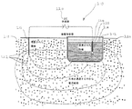
図面についての以下の説明において、類似の参照番号は類似の要素を示す。図1は、本発明の方法及びシステムの第1の実施形態の概略断面図10を示す。この実施形態は、湖、池、又は貯水槽といった自然の水塊12の中の不純物を処理するのに用いられる。実質的に平坦な陰極(例えばメッシュ又はプレート)14を具備する第1の電極装置は、水塊12の中に浸漬され、水塊12内の一定領域を覆っている。陽極棒材16を具備する第2の電極装置は、水塊12を包囲する大地18に埋設されている。大地18は、水塊12用の水収容手段として有効に機能する。実質的に平坦な陰極14及び陽極棒材16は、DC電圧供給源20を具備する電源装置の負端子及び正端子にそれぞれ接続されている。DC電圧供給源20は可調節になっていて、0V〜−100Vの電圧を提供するようになっており、それによって、電流流跡線22で示される電界が水塊12及び周辺大地18に発生する。電圧が調節されて、最終的に、次のプロセスの一方又は両方を実施するのに十分な強度及び継続時間の電界が実現される。
(i)水から無機不純物を分離するのを助けるために、それらの集積を局所化すること。
(ii)水を電離して、有機不純物及び/又は無機不純物を処理するための溶存酸素種及び溶存水素種を生成すること。
In the following description of the drawings, like reference numerals indicate like elements. FIG. 1 shows a schematic
(I) localizing their accumulation to help separate inorganic impurities from water.
(Ii) ionizing water to produce dissolved oxygen species and dissolved hydrogen species for treating organic and / or inorganic impurities;
本発明の方法及びシステムの第2、第3、及び第4の実施形態をそれぞれ図解する図2、図3、及び図4についての以下の説明では、第1の実施形態のものとは異なるこれら実施形態の特徴に焦点を合わせて論じることにする。 In the following description of FIGS. 2, 3 and 4 illustrating the second, third and fourth embodiments of the method and system of the present invention respectively, these differ from those of the first embodiment. The discussion will focus on the features of the embodiment.
図2では、導電性の容器124を具備する水収容手段の中に水塊112が入れられている。したがって、電流流跡線122は、電源装置120から埋設された陽極116、大地118、導電性容器124の壁を経由して水塊112に進入し、次いで、浸漬された実質的に平坦な陰極114に進んで電源装置120に戻る。
In FIG. 2, a water mass 112 is placed in a water storage means having a conductive container 124. Thus, the
図3は変形例を示している。同図において、第1の電極装置は、非導電性筐体228内部に陰極226を具備した、浸漬状態の陰極性装置214である。後で行う図5の論述において、陰極装置214をより詳細に説明する。
FIG. 3 shows a modification. In the figure, the first electrode device is an immersed
図4は、更に別の変形例を示している。同図において、第2の電極装置は、導電性の容器324の外壁内に設けられた陽極316を備えている。陽極316は、容器324の外壁の中に組み込まれた導電性のメッシュを備えている。外壁は、物理的には水と接触していない。したがって、電流流跡線322で表される電界は、完全に導電性容器324及び水塊312の内部にあるのであって、外方向に延伸して周辺の大地318まで及ぶことはない。
FIG. 4 shows still another modification. In the figure, the second electrode device includes an
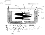
図5は、図3に関連して説明された電極装置214を一層詳細に示している。電極装置214は、ステンレス鋼の棒状電極226を中に収容する非導電性筐体228を具備する。この非導電性筐体228は、ポリ塩化ビニルで構成されるとともに、PVCの管体230を具備する本体を具備しており(一部が切り欠かれて図5に示されている)、同じくPVCで作られた流出導管232は、そこから横方向に延伸している。
FIG. 5 shows in more detail the
PVC管体230の上方端部には、装着キャップ234が設けられている。電極226の端部236は、このキャップを貫通して延在するとともに、ナット238によってそこに装着されている。電極端部236とナット238は一体的に端子を形成しており、そこに電気ケーブル240を取り付けて電源装置220との接続を行うことができる。
A mounting cap 234 is provided at the upper end of the
PVC管体230の下方開放端部には、水塊212からの不純物含有水がそこから電極装置214に入る入口242が設けられている。
An inlet 242 from which impurity-containing water from the
流出導管232の端部には出口244が設けられており、水は処理を受けた後、そこを通って電極装置から出て行く。
An
電極装置は、符号248で模式的に示す圧縮空気ポンプに接続するための開口246を含む酸化体の流れ取り込み用の手段を更に具備している。空気ポンプ248は、空気揚水ポンプとして動作するように構成されており、汚水が、入口242からPVC管体230を通り、そこで電極に接触しながら流出導管232の外に移動するのを支援する。加えて、空気ポンプ248によって酸素を導入することは、電解プロセスによって生成される溶存酸素のレベルを高め、溶液中でおそらく酸素の過飽和をもたらすであろう。かかる化学的環境は、微生物の呼吸及び成長を速め、有機不純物及び/又は無機不純物を含む栄養分の消化能力を高める。
The electrode device further comprises means for oxidant flow uptake including an
更に、この電解プロセスはイオンの電極への移動をもたらし(この場合、電極が電源供給手段の負端子に接続されているときは陽イオン)、そこでこれらのイオンは酸化又は還元され、且つ/又は溶液に陰イオンが存在する状態で結晶格子を形成する。 Furthermore, this electrolysis process results in the movement of ions to the electrode (in this case a cation when the electrode is connected to the negative terminal of the power supply means), where these ions are oxidized or reduced and / or A crystal lattice is formed in the presence of anions in the solution.
本発明の第2、第3、及び第4の電極装置をそれぞれ図解する図6、図7、及び図8についての以下の説明では、電極装置の第1の実施形態のものとは異なるこれら実施形態の特徴に焦点を合わせて論じることにする。 In the following description of FIGS. 6, 7 and 8 illustrating the second, third and fourth electrode devices of the present invention respectively, these implementations differ from those of the first embodiment of the electrode device. The discussion will focus on the features of the form.
図6は、電極装置414の別の実施形態を示す。この電極装置は、2つの小室462,464間を分離する壁460を、水塊412内で横切って延在する。
FIG. 6 shows another embodiment of the electrode device 414. The electrode device extends across a water mass 412 across a
電極装置414は、個別の第1の電極426a,bが中に設けられた筐体428を備えている。これら第1の電極は、第1のPVC管体及び第2のPVC管体430a,bそれぞれの中に実質的に同軸状に装着されている。PVC管体430a,bは、やはりPVC管体を含んで構成された、分離壁460を貫通する架橋コンポーネント466によって、上方近位端部付近で互いに連結されている。
The electrode device 414 includes a housing 428 in which individual first electrodes 426a and 426b are provided. These first electrodes are mounted substantially coaxially in each of the first PVC pipe body and the second PVC pipe bodies 430a, 430b. The PVC tubes 430a, b are connected to each other near the upper proximal end by a bridging component 466 penetrating the
汚水の流れは、第1のPVC管体430aの下方遠位端部に位置する第1の入口442aを介して電極装置414に進入する。この水の流れは、点線468で表される経路を辿り、第1の電極426aの周囲を移動しながら通過し、第1の出口444aを経由して架橋コンポーネント466に進入する。次いで、流れは、第2のPVC管体430bの上方近位端部に位置する第2の入口442bに入り、第2の電極426bの周囲を流れながら通過し、第2のPVC管体430bの下方遠位端部に位置する第2の出口44bを通って流出する。 The wastewater flow enters the electrode device 414 via the first inlet 442a located at the lower distal end of the first PVC tube 430a. This water flow follows a path indicated by a dotted line 468, passes while moving around the first electrode 426a, and enters the bridging component 466 via the first outlet 444a. The flow then enters a second inlet 442b located at the upper proximal end of the second PVC tube 430b, passes around the second electrode 426b, and passes through the second PVC tube 430b. Outflow through the second outlet 44b located at the lower distal end.
図6に示す構成は、水が処理されているときの再循環を促進し、それによって溶存酸素に対する不純物の露出を最大化し、ひいては浄化の効率を高める。 The configuration shown in FIG. 6 facilitates recirculation when the water is being treated, thereby maximizing the exposure of impurities to dissolved oxygen and thus increasing the purification efficiency.
次に図7について説明する。同図には、非導電性筐体528内部に螺旋又は渦巻き状の電極526が設けられた電極装置514が示されている。非導電性筐体528は、筐体528の下方端部に位置する入口542と、それの上方端部に位置する出口544と、を具備する。入口542に隣接して開口546が設けられており、全体として548で表される圧縮空気の供給源に接続される。螺旋電極526は汚水と接触する比較的大きな表面積を有し、それによって電極の影響に対する不純物の露出を最大化している。
Next, FIG. 7 will be described. In the drawing, an electrode device 514 in which a spiral or spiral electrode 526 is provided inside a non-conductive housing 528 is shown. The non-conductive housing 528 includes an inlet 542 located at the lower end of the housing 528 and an outlet 544 located at the upper end thereof. An
図8a及び図8bは、本発明の電極装置の第4の実施形態を示す。非導電性筐体628と、電極と、を具備する電極装置614が示されているが、この電極は上方端部636だけが見えている。非導電性筐体628は、筐体628の下方端部に位置する入口642と、それの上方端部に位置する出口644と、を具備する。
8a and 8b show a fourth embodiment of the electrode device of the present invention. An
圧縮空気の供給源648は、圧縮空気管体649を介して、分散小室647を具備する開口646で非導電性筐体に接続されている。この小室は、合算した断面積が圧縮空気管体649の断面積より小さい多数の穴(図示せず)で構成されている。 The compressed air supply source 648 is connected to the non-conductive casing through the compressed air tube 649 through an opening 646 having a dispersion chamber 647. This small chamber is composed of a number of holes (not shown) whose combined cross-sectional area is smaller than that of the compressed air tube 649.
更に、電極装置614は、全体として符号670で表されるガス拡散手段も具備する。このガス拡散手段は、マイクロバブルを上に形成するための多数の基体672を具備する。基体672は、非導電性筐体内部で実質的に軸方向に延在する複数のプラスチックの帯674の表面を構成する。各プラスチックの帯674は、拡大されたそれの一方の端部676によって、非導電性筐体628の壁の中に設けられた該当の穴678に係止される。穴678は、非導電性筐体628の周囲に実質的に螺旋パターンで配置されている。帯674は、係止された拡大端部676から実質的に下流方向に延在するように構成されている。
Furthermore, the
図8bは、各穴678とその中に挿着されたプラスチックの帯674の拡大端部との間を封着する目的で、非導電性筐体628の外面に装備された密封スリーブ680を具備する電極装置614を示す。密封スリーブ680は、水密封着を確保するために、縮められて非導電性筐体628に嵌着されている。
FIG. 8b includes a sealing sleeve 680 mounted on the outer surface of the non-conductive housing 628 for the purpose of sealing between each hole 678 and the enlarged end of the
第4の実施形態614を使用する際に、空気が、バブルの流れとして、分散小室647を介して、入口642から流れて来る汚水に導入される。結果的に非導電性筐体628内の水の密度が下がると、この曝気水は、上昇するとともに更なる水を入口642に引き込む。曝気水は、上昇するときにガス拡散手段670を通過する。そこでは、上記の空気バブルが基体上の核形成部位と協働して、マイクロバブルを形成する。マイクロバブルを含有する水は、単に曝気を受けただけの水に比べて、遥かに高い溶存酸素レベルを呈する。溶存酸素のレベルは、電極端部636下方に延在する電極での電解による酸素の生成によって、一層高めることができる。
In using the
図9a,図9b及び図9cは、導電性部材(直径103mmの円盤)を示す。この部材は、表面積を増加させる目的で、本明細書に記載の任意の電極に嵌合することができる。この実施形態において、屈曲線は、円盤の中心から26.5mmである。矢印は、各円盤の中央装着窓の位置を示している。 9a, 9b, and 9c show a conductive member (a disk having a diameter of 103 mm). This member can be fitted to any of the electrodes described herein for the purpose of increasing the surface area. In this embodiment, the bend line is 26.5 mm from the center of the disk. The arrow indicates the position of the central mounting window of each disk.
図10は、(図9b及び9cに示すような)導電性部材702を多数嵌合させた棒状電極700を示す。この電極は、密閉蓋706と、空気ライン入力部708と、取水部710と、水/空気流出部712と、を有する空気揚水筐体704の中に配置されている。水は取水部710に入り、入力ライン708によって導入された空気と一緒に拡散される。この水と空気との混合体は、上方向に、電極700及び導電性部材702の周りを通って移動する。これらの導電性部材は、屈曲領域がこの棒状電極に付設されている上方及び下方の部材と対向する部材となるような形で配置されている。より回旋状の態様で筐体を上がって通過する経路を水及び空気に進ませる必要があることは明らかであるものの、導電性部材は、流量が大幅に妨げられないような形で設計されるとともに配置されている。
FIG. 10 shows a rod-
下記の非限定的実施例を参照して、本発明を以下に更に詳細に説明する。 The invention is described in more detail below with reference to the following non-limiting examples.
[実施例1:網状の廃水の取り扱い]
本発明の電解処理法に従って、2種類の網状の廃水システムが取り扱われた。各システムは、図6に例示されているように、隣接する小室間に電極装置を備えていた。
[Example 1: Handling of network wastewater]
In accordance with the electrolytic treatment method of the present invention, two types of reticulated wastewater systems were handled. Each system was equipped with an electrode device between adjacent chambers, as illustrated in FIG.
システム1では、テスト期間全体にわたって空気揚水ポンプを介して空気を導入することにより、廃水は追加的に処理された。システム2の廃水は最初に曝気され、その後曝気は停止された。
In
各システムの水は、約5ヶ月隔てて、2回解析された。水は、提示のAPHA Standard Methods for the Examination of Water and Wastewater (20th Ed) 1998を用いて、下記の品質項目について解析された。
生物化学的酸素消費量 APHA 5210B
総懸濁物質 APHA 2540D
溶存酸素 APHA 4500−OC
The water in each system was analyzed twice, approximately 5 months apart. Water was analyzed for the following quality items using the proposed APHA Standard Methods for the Examination of Water and Wastewater (20th Ed) 1998.
Biochemical oxygen consumption APHA 5210B
Total suspended material APHA 2540D
Dissolved oxygen APHA 4500-OC
解析結果は下記の通りである。 The analysis results are as follows.

25℃、圧力1atmにおける酸素の水溶性が40mg/Lであることから、溶存酸素レベルは特に興味深い。通常の組成の空気では、酸素分圧は0.2atmである。この結果、曝気手段だけの場合に、溶解性は最大で40×0.2=8mg/Lということになる。(20℃、海抜0mの高さで、機械的曝気による最大達成可能溶存酸素は9.18mg/Lである。) The dissolved oxygen level is particularly interesting because the water solubility of oxygen at 25 ° C. and 1 atm pressure is 40 mg / L. In air with a normal composition, the oxygen partial pressure is 0.2 atm. As a result, when only the aeration means is used, the maximum solubility is 40 × 0.2 = 8 mg / L. (The maximum achievable dissolved oxygen by mechanical aeration is 9.18 mg / L at 20 ° C and 0 m above sea level.)
これらの結果は、どちらのシステムでも、この最大レベル付近又はそれ以上のレベルで溶存酸素が維持されていることを示している。 These results indicate that dissolved oxygen is maintained at or near this maximum level in both systems.
テスト期間全体にわたる連続的曝気を含むシステム1において、水は、後の測定日に、上記の結果の他に低減されたBOD値及び低減されたTSS値を明らかに呈している。
In
[実施例2:網状の廃水の取り扱い(2)]
本発明の方法に従って、ある網状の廃水システムが取り扱われた。空気揚水ポンプ循環の構成の60Wのコンプレッサを用いて2ヶ月間連続して曝気を行った後で、各好気性小室は、3〜5ppmの過酸化水素を示した。
[Example 2: Handling of reticulated wastewater (2)]
In accordance with the method of the present invention, a reticulated wastewater system was handled. After continuous aeration for 2 months using a 60 W compressor configured for air pumping pump circulation, each aerobic chamber showed 3-5 ppm hydrogen peroxide.
終わりにあたり、種々の他の変更及び/又は改変は、本明細書で概説した本発明の精神から逸脱することなく行い得るのであり、このことは理解されている必要がある。 At the end, various other changes and / or modifications may be made without departing from the spirit of the invention as outlined herein, which should be understood.
Claims (46)
(a)少なくとも1つの第1の電極装置に前記水を接触させることと、
(b)非物理的で電気的な態様で前記水と接触する少なくとも1つの第2の電極装置を設けることと、
(c)前記水の中に、
(i)前記水から前記無機不純物を分離するのを助けるために、それらの集積を局所化すること、及び
(ii)水を電離して、前記有機不純物及び/又は無機不純物を処理するための溶存酸素種及び溶存水素種を生成すること、
の一方又は両方のプロセスを実施するのに十分な強度及び継続時間の電界を構築するように、前記第2の電極装置と前記第1の電極装置との間に電流を通すことと、
を含む方法。 An electrolytic method for treating water having organic and / or inorganic impurities therein,
(A) contacting the water with at least one first electrode device;
(B) providing at least one second electrode device in contact with the water in a non-physical and electrical manner;
(C) In the water,
(I) localizing their accumulation to help separate the inorganic impurities from the water; and (ii) ionizing the water to treat the organic and / or inorganic impurities. Producing dissolved oxygen species and dissolved hydrogen species;
Passing an electric current between the second electrode device and the first electrode device so as to build an electric field of sufficient strength and duration to perform one or both of the processes of:
Including methods.
前記筐体内に配置された1つ又は複数の電極と、
前記筐体内の入口及び出口であって、前記1つ又は複数の電極と接触するような形で不純物含有水にその筐体を通過させるための入口及び出口と、
前記1つ又は複数の電極を電源装置に接続するための手段と、
を具備している電極装置。 A non-conductive housing;
One or more electrodes disposed within the housing;
An inlet and outlet in the housing for allowing the water containing impurities to pass through the housing in contact with the one or more electrodes;
Means for connecting the one or more electrodes to a power supply;
An electrode device comprising:
(a)前記水と接触する少なくとも1つの第1の電極装置と、
(b)非物理的で電気的な態様で前記水と接触する少なくとも1つの第2の電極装置と、
(c)前記水の中に、
(i)前記水から前記無機不純物を分離するのを助けるために、それらの集積を局所化すること、及び
(ii)水を電離して、前記有機不純物及び/又は無機不純物を処理するための溶存酸素種及び溶存水素種を生成すること、
の一方又は両方のプロセスを実施するのに十分な強度及び継続時間の電界を構築する目的で、前記第1及び第2の電極装置と電気的に接続するための電源装置と、
を具備するシステム。 A system for use in an electrolysis process for treating water having organic and / or inorganic impurities therein,
(A) at least one first electrode device in contact with the water;
(B) at least one second electrode device in contact with the water in a non-physical and electrical manner;
(C) In the water,
(I) localizing their accumulation to help separate the inorganic impurities from the water; and (ii) ionizing the water to treat the organic and / or inorganic impurities. Producing dissolved oxygen species and dissolved hydrogen species;
A power supply for electrical connection with the first and second electrode devices for the purpose of constructing an electric field of sufficient strength and duration to perform one or both of the processes;
A system comprising:
非導電性筐体と、
前記筐体内に配置された1つ又は複数の電極と、
前記筐体内の入口及び出口であって、前記1つ又は複数の電極と接触するような形で不純物含有水にその筐体を通過させるための入口及び出口と、
前記1つ又は複数の電極を前記電源装置に接続するための手段と、
を具備している、請求項33に記載のシステム。 The first electrode device comprises:
A non-conductive housing;
One or more electrodes disposed within the housing;
An inlet and outlet in the housing for allowing the water containing impurities to pass through the housing in contact with the one or more electrodes;
Means for connecting the one or more electrodes to the power supply;
34. The system of claim 33, comprising:
前記拡散器筐体内の1つ又は複数の基体であって、前記酸化ガスのマイクロバブルを形成するための核形成部位を提供するように構成され且つ配設された1つ又は複数の基体と、
を具備するガス拡散装置。 A diffuser housing with an inlet and an outlet for passing a water stream containing gas;
One or more substrates within the diffuser housing, the one or more substrates configured and arranged to provide a nucleation site for forming the microbubbles of the oxidizing gas;
A gas diffusion device comprising:
Applications Claiming Priority (3)
| Application Number | Priority Date | Filing Date | Title |
|---|---|---|---|
| US2909508P | 2008-02-15 | 2008-02-15 | |
| US3786808P | 2008-03-19 | 2008-03-19 | |
| PCT/AU2009/000168 WO2009100496A1 (en) | 2008-02-15 | 2009-02-16 | Method system and device for treatment of water |
Publications (1)
| Publication Number | Publication Date |
|---|---|
| JP2011511709A true JP2011511709A (en) | 2011-04-14 |
Family
ID=40956561
Family Applications (1)
| Application Number | Title | Priority Date | Filing Date |
|---|---|---|---|
| JP2010546185A Pending JP2011511709A (en) | 2008-02-15 | 2009-02-16 | Method, system and apparatus for water treatment |
Country Status (10)
| Country | Link |
|---|---|
| US (1) | US8641886B2 (en) |
| EP (1) | EP2250130A4 (en) |
| JP (1) | JP2011511709A (en) |
| CN (1) | CN102036920A (en) |
| AU (1) | AU2009214831A1 (en) |
| CA (1) | CA2714993A1 (en) |
| IL (1) | IL207585A0 (en) |
| MX (1) | MX2010008911A (en) |
| RU (1) | RU2010138099A (en) |
| WO (1) | WO2009100496A1 (en) |
Cited By (1)
| Publication number | Priority date | Publication date | Assignee | Title |
|---|---|---|---|---|
| JP2015524352A (en) * | 2012-08-06 | 2015-08-24 | セグレゲーション オブ メタル システム エス.アール.エル. | Methods and facilities for reducing the concentration of pollutants and / or valuable elements in water |
Families Citing this family (7)
| Publication number | Priority date | Publication date | Assignee | Title |
|---|---|---|---|---|
| US20130134053A1 (en) * | 2009-11-24 | 2013-05-30 | Iogenyx Pty Ltd | Methods and devices for the treatment of fluids |
| US10160669B2 (en) | 2009-11-24 | 2018-12-25 | Glass Circle Investments Pty Ltd | Methods and devices for the treatment of fluids |
| US9907896B2 (en) | 2013-06-21 | 2018-03-06 | Taipei Medical University | Apparatus and process for preparation of small water cluster and small molecular cluster water prepared therefrom |
| CN108408992A (en) * | 2018-01-25 | 2018-08-17 | 中国地质大学(武汉) | A kind of regulation and control method in situ of water-bearing layer Redox Condition |
| CN110102566A (en) * | 2019-03-19 | 2019-08-09 | 广东筑奥生态环境股份有限公司 | A kind of heavy metal adsorption method for the modified reparation of soil pollution |
| GB2591282B (en) * | 2020-01-24 | 2024-05-29 | Hydrolize Ltd | Water remediation system |
| CN111842451B (en) * | 2020-08-07 | 2022-04-15 | 中国水电基础局有限公司 | Modularized underground water permeable reactive pile and implementation method thereof |
Family Cites Families (12)
| Publication number | Priority date | Publication date | Assignee | Title |
|---|---|---|---|---|
| DE3690472D2 (en) * | 1985-09-20 | 1987-10-08 | Nogler & Daum Eltac | Method and device for the oxygen enrichment of waters |
| US5738778A (en) * | 1995-02-28 | 1998-04-14 | P + P Geotechnik Gmbh Ingenieure Fur Boden-Und Grundwassersanierungen | Method related to the sterilization of microorganisms and/or to the mineralization of organic substances including microbic metabolites in a ground region and in the ground water by means of electric current |
| US5728287A (en) * | 1996-10-31 | 1998-03-17 | H2 O Technologies, Ltd. | Method and apparatus for generating oxygenated water |
| JP2000117240A (en) * | 1998-10-14 | 2000-04-25 | Inax Corp | Supplying device for reuse of waste water |
| US6391184B1 (en) * | 1999-12-17 | 2002-05-21 | H2O Technologies, Ltd. | Decontamination method and system, such as an in-situ groundwater decontamination system, producing dissolved oxygen and reactive initiators |
| ATE295237T1 (en) * | 2000-02-10 | 2005-05-15 | Falk Dr Doering | METHOD FOR REMOVAL OF INORGANIC COMPOUNDS FROM A SOIL AREA |
| US6321837B1 (en) * | 2000-05-22 | 2001-11-27 | Falk Doering | Method and device for the in-situ elimination of hazardous substances from the groundwater and perched water |
| AUPR566701A0 (en) * | 2001-06-14 | 2001-07-12 | Rmg Services Pty. Ltd. | Electrolytic activation of fluids |
| US6758959B2 (en) * | 2002-02-12 | 2004-07-06 | Jerry Kellgren | Method and apparatus for oxygenating ground water |
| NZ534551A (en) * | 2004-08-06 | 2006-01-27 | Water Rite Ltd | Water treament apparatus with bacterial culture medium |
| NZ549234A (en) * | 2006-08-16 | 2006-10-27 | Water Rite Ltd | Electrolytic water treatment with immersed low voltage active cathode |
| WO2008098298A1 (en) * | 2007-02-16 | 2008-08-21 | Iogenyx Pty Ltd | Methods for improving the cultivation of aquatic organisms |
-
2009
- 2009-02-16 CN CN2009801134797A patent/CN102036920A/en active Pending
- 2009-02-16 CA CA 2714993 patent/CA2714993A1/en not_active Abandoned
- 2009-02-16 US US12/867,578 patent/US8641886B2/en not_active Expired - Fee Related
- 2009-02-16 AU AU2009214831A patent/AU2009214831A1/en not_active Abandoned
- 2009-02-16 WO PCT/AU2009/000168 patent/WO2009100496A1/en not_active Ceased
- 2009-02-16 JP JP2010546185A patent/JP2011511709A/en active Pending
- 2009-02-16 EP EP09710227A patent/EP2250130A4/en not_active Withdrawn
- 2009-02-16 MX MX2010008911A patent/MX2010008911A/en not_active Application Discontinuation
- 2009-02-16 RU RU2010138099/05A patent/RU2010138099A/en not_active Application Discontinuation
-
2010
- 2010-08-12 IL IL207585A patent/IL207585A0/en unknown
Cited By (1)
| Publication number | Priority date | Publication date | Assignee | Title |
|---|---|---|---|---|
| JP2015524352A (en) * | 2012-08-06 | 2015-08-24 | セグレゲーション オブ メタル システム エス.アール.エル. | Methods and facilities for reducing the concentration of pollutants and / or valuable elements in water |
Also Published As
| Publication number | Publication date |
|---|---|
| CA2714993A1 (en) | 2009-08-20 |
| US8641886B2 (en) | 2014-02-04 |
| MX2010008911A (en) | 2010-11-05 |
| IL207585A0 (en) | 2010-12-30 |
| EP2250130A1 (en) | 2010-11-17 |
| CN102036920A (en) | 2011-04-27 |
| WO2009100496A1 (en) | 2009-08-20 |
| AU2009214831A1 (en) | 2009-08-20 |
| RU2010138099A (en) | 2012-03-20 |
| US20110089049A1 (en) | 2011-04-21 |
| EP2250130A4 (en) | 2012-11-07 |
Similar Documents
| Publication | Publication Date | Title |
|---|---|---|
| JP2011511709A (en) | Method, system and apparatus for water treatment | |
| EP1161400B1 (en) | Method and apparatus for treatment of organic matter-containing wastewater | |
| US7011750B2 (en) | Water treatment device | |
| JP2000051894A (en) | Sewage treatment apparatus | |
| WO1995021795A1 (en) | Electrocatalytic dissolved oxygen generator for water processing | |
| JP2002346566A (en) | Apparatus and method for water treatment | |
| CN1237011C (en) | Water purifying device | |
| EP1470081B1 (en) | Device for electrolytic purification of liquids | |
| CN212315715U (en) | Online water quality stabilization equipment of hydrologic cycle | |
| EP3939940B1 (en) | Arrangement comprising an electrolytic cell | |
| RU2378202C2 (en) | Method and device for saturating liquid with gas | |
| CN1122642C (en) | Water treatment method and its equipment | |
| CN104936906B (en) | The method that electrochemical disinfection is carried out to water | |
| JP2006095466A (en) | Electrolyzer, purifying tank having the electrolyzer and electrolytic method | |
| WO2018176166A1 (en) | Liquid waste treatment plant which uses the fenton system for reducing organic molecules | |
| JP3913580B2 (en) | Electrolytic sewage treatment apparatus and sewage treatment facility using the same | |
| JP5702198B2 (en) | Water treatment method | |
| JP4270825B2 (en) | Electrolytic wastewater treatment equipment | |
| JP2001252668A (en) | Sewage treating device | |
| JP4111970B2 (en) | Water treatment equipment | |
| KR200287661Y1 (en) | Water treatment apparatus | |
| JPH11188365A (en) | Sewage treatment apparatus | |
| JPH1157725A (en) | Device for treating phosphate ion-containing waste water | |
| JP2000167560A (en) | Treatment apparatus of phosphate ion-containing water | |
| JP2003018937A (en) | Aquatic organism raising system and method for cleaning raising water |