JP2011232444A - Coordinate conversion device, coordinate conversion method and program - Google Patents
Coordinate conversion device, coordinate conversion method and program Download PDFInfo
- Publication number
- JP2011232444A JP2011232444A JP2010101015A JP2010101015A JP2011232444A JP 2011232444 A JP2011232444 A JP 2011232444A JP 2010101015 A JP2010101015 A JP 2010101015A JP 2010101015 A JP2010101015 A JP 2010101015A JP 2011232444 A JP2011232444 A JP 2011232444A
- Authority
- JP
- Japan
- Prior art keywords
- coordinate system
- reference points
- coordinates
- coordinate
- target point
- Prior art date
- Legal status (The legal status is an assumption and is not a legal conclusion. Google has not performed a legal analysis and makes no representation as to the accuracy of the status listed.)
- Granted
Links
Images


Landscapes
- Instructional Devices (AREA)
- Navigation (AREA)
Abstract
Description
本発明は、基準の地図とデフォルメされた地図との間における座標変換に関する。 The present invention relates to coordinate conversion between a reference map and a deformed map.
地図には、特徴的な場所を強調したりわかりやすくしたりするために、縮尺を歪めて表示したものなどがある。このような地図は、実際の縮尺で記述された地図の座標との対応関係が複雑である。特許文献1には、GPS(Global Positioning System)により取得された実際の座標情報をデフォルメ地図上に表示させるために、計測地図(実際の地図)とデフォルメ地図とから基準点を抽出及び選択し、補間計算によってデフォルメ地図上の座標情報を算定する方法が記載されている。
There are maps that are displayed with the scales distorted in order to emphasize characteristic places or make them easy to understand. Such a map has a complicated correspondence with the coordinates of the map described in actual scale. In
特許文献1に記載された技術は、基準点がふんだんに用意されていないと、有効に機能しにくいものである。しかし、このような基準点をあらかじめ多数用意することは、手間のかかることであり、容易なことではない。
そこで、本発明は、ある地図からデフォルメされた地図への座標変換(又はその逆変換)において、基準点が少ない場合においてもより正確な位置に変換を行えるようにすることを目的とする。
The technique described in
Therefore, an object of the present invention is to make it possible to perform conversion to a more accurate position even when there are few reference points in coordinate conversion from a map to a deformed map (or vice versa).
本発明の一態様に係る座標変換装置は、基準の第1の座標系と異なる第2の座標系で記述された地図上に、前記第1の座標系の座標と前記第2の座標系の座標との対応関係が既知である複数の基準点を設定する基準点設定部と、前記地図上の前記第2の座標系の座標が未知である対象点に対応する前記第1の座標系の座標を取得する座標取得部と、前記基準点設定部により設定された複数の基準点から、前記第1の座標系の座標が前記座標取得部により取得された座標に近接する3個の基準点を選択する選択部と、前記選択部により選択された3個の基準点の前記第1の座標系及び前記第2の座標系の座標を用いて、前記対象点の前記第2の座標系の座標を算出する算出部とを備え、前記選択部は、3個の基準点の組合せが所定の条件を満たさない場合に、他の3個の基準点の組合せを再選択し、前記算出部は、前記選択部により前記組合せが再選択された場合に、当該再選択された3個の基準点を用いる構成を有する。 The coordinate conversion device according to one aspect of the present invention includes a coordinate described in a second coordinate system different from a reference first coordinate system, the coordinates of the first coordinate system, and the coordinates of the second coordinate system. A reference point setting unit for setting a plurality of reference points whose correspondence with coordinates is known; and a first coordinate system corresponding to a target point whose coordinates of the second coordinate system on the map are unknown From the coordinate acquisition unit for acquiring coordinates and the plurality of reference points set by the reference point setting unit, the three reference points in which the coordinates of the first coordinate system are close to the coordinates acquired by the coordinate acquisition unit Using the coordinates of the first coordinate system and the second coordinate system of the three reference points selected by the selection unit, and the coordinates of the second coordinate system of the target point A calculation unit that calculates coordinates, and the selection unit includes a combination of three reference points that satisfies a predetermined condition. If not, the calculation unit re-selects another combination of three reference points, and the calculation unit uses the three re-selected reference points when the selection unit re-selects the combination. Have
好ましい態様において、前記選択部は、前記第1の座標系で表される平面において、前記3個の基準点を頂点とする平行四辺形に前記対象点が含まれることを前記条件に用いて前記再選択の要否を判定する判定部を有する。
他の好ましい態様において、前記選択部は、前記第1の座標系で表される平面において、前記3個の基準点の1個を重心とし、他の2個を辺の中点とする平行四辺形に前記対象点が含まれることを前記条件に用いて前記再選択の要否を判定する判定部を有する。
他の好ましい態様において、前記選択部は、前記第1の座標系で表される平面において、前記3個の基準点を頂点又は辺に含む四角形に前記対象点が含まれることを前記条件に用いて前記再選択の要否を判定する判定部を有する。
他の好ましい態様において、前記選択部は、前記第1の座標系で表される平面を前記対象点を中心に4以上の区域に分割した場合に、前記対象点に最も近い前記基準点を当該分割された区域から1個ずつ抽出し、当該抽出した基準点から前記組合せを選択及び再選択する。この態様において、前記分割の数が4であり、前記選択部は、前記組合せとして、前記分割された4区域から抽出された4個の基準点から3個の基準点を選ぶ組合せを用いると、より好ましい。
他の好ましい態様において、前記選択部は、前記第1の座標系で表される平面を前記対象点を中心に3以上の区域に分割した場合に、前記3個の基準点が当該分割された区域のいずれかにも2個以上含まれないことを前記条件に用いて前記再選択の要否を判定する判定部を有する。
In a preferred aspect, the selection unit uses the condition that the target point is included in a parallelogram having the three reference points as vertices in the plane represented by the first coordinate system. It has the determination part which determines the necessity of reselection.
In another preferable aspect, the selection unit has parallel four sides having one of the three reference points as the center of gravity and the other two as the midpoints of the sides in the plane represented by the first coordinate system. A determination unit that determines whether or not the reselection is necessary using the condition that the target point is included in the shape;
In another preferable aspect, the selection unit uses, as the condition, that the target point is included in a quadrilateral that includes the three reference points at a vertex or a side in a plane represented by the first coordinate system. A determination unit for determining whether the reselection is necessary.
In another preferred aspect, the selection unit divides the reference point closest to the target point when the plane represented by the first coordinate system is divided into four or more areas around the target point. One by one is extracted from the divided areas, and the combination is selected and reselected from the extracted reference points. In this aspect, when the number of divisions is 4, and the selection unit uses a combination of selecting three reference points from four reference points extracted from the four divided areas as the combination, More preferred.
In another preferable aspect, when the selection unit divides the plane represented by the first coordinate system into three or more areas around the target point, the three reference points are divided. The determination unit determines whether or not the reselection is necessary using the condition that two or more of the areas are not included in any of the areas.
本発明の他の態様に係る座標変換方法は、基準の第1の座標系と異なる第2の座標系で記述された地図上に、前記第1の座標系の座標と前記第2の座標系の座標との対応関係が既知である複数の基準点を設定する第1ステップと、前記地図上の前記第2の座標系の座標が未知である対象点に対応する前記第1の座標系の座標を取得する第2ステップと、前記第1ステップにおいて設定された複数の基準点から、前記第1の座標系の座標が前記第2ステップにおいて取得された座標に近接する3個の基準点を選択する第3ステップと、前記第3ステップにおいて選択された3個の基準点の前記第1の座標系及び前記第2の座標系の座標を用いて、前記対象点の前記第2の座標系の座標を算出する第4ステップとを実行し、前記第3ステップにおいて、3個の基準点の組合せが所定の条件を満たさない場合に、他の3個の基準点の組合せを再選択し、前記第3ステップにおいて前記組合せが再選択された場合に、前記第4ステップにおいて当該再選択された3個の基準点を用いることを特徴とするものである。 According to another aspect of the present invention, there is provided a coordinate conversion method in which the coordinates of the first coordinate system and the second coordinate system are displayed on a map described in a second coordinate system different from the reference first coordinate system. A first step of setting a plurality of reference points whose correspondence to the coordinates of the first coordinate system is known; and a first coordinate system corresponding to a target point whose coordinates of the second coordinate system on the map are unknown From the second step of acquiring the coordinates and a plurality of reference points set in the first step, three reference points whose coordinates in the first coordinate system are close to the coordinates acquired in the second step are obtained. The second coordinate system of the target point using the third step to be selected and the coordinates of the first coordinate system and the second coordinate system of the three reference points selected in the third step And a fourth step of calculating the coordinates of When the combination of the three reference points does not satisfy the predetermined condition, the combination of the other three reference points is reselected, and when the combination is reselected in the third step, The four re-selected reference points are used in four steps.
本発明の他の態様に係るプログラムは、コンピュータに、基準の第1の座標系と異なる第2の座標系で記述された地図上に、前記第1の座標系の座標と前記第2の座標系の座標との対応関係が既知である複数の基準点を設定する第1ステップと、前記地図上の前記第2の座標系の座標が未知である対象点に対応する前記第1の座標系の座標を取得する第2ステップと、前記第1ステップにおいて設定された複数の基準点から、前記第1の座標系の座標が前記第2ステップにおいて取得された座標に近接する3個の基準点を選択する第3ステップと、前記第3ステップにおいて選択された3個の基準点の前記第1の座標系及び前記第2の座標系の座標を用いて、前記対象点の前記第2の座標系の座標を算出する第4ステップとを実行させるためのプログラムであって、前記第3ステップにおいて、3個の基準点の組合せが所定の条件を満たさない場合に、他の3個の基準点の組合せを再選択し、前記第3ステップにおいて前記組合せが再選択された場合に、当該再選択された3個の基準点を前記第4ステップにおいて用いることを特徴とするものである。 According to another aspect of the present invention, there is provided a program that stores, on a map described in a second coordinate system different from a reference first coordinate system, the coordinates of the first coordinate system and the second coordinates. A first step of setting a plurality of reference points whose correspondence with the coordinates of the system is known; and the first coordinate system corresponding to a target point whose coordinates of the second coordinate system on the map are unknown The second step of acquiring the coordinates of the three and the three reference points in which the coordinates of the first coordinate system are close to the coordinates acquired in the second step from the plurality of reference points set in the first step And the second coordinates of the target point using the coordinates of the first coordinate system and the second coordinate system of the three reference points selected in the third step. To execute the fourth step of calculating the coordinates of the system In the third step, when the combination of the three reference points does not satisfy the predetermined condition in the third step, the combination of the other three reference points is reselected, and the combination in the third step When reselected, the three reselected reference points are used in the fourth step.
本発明によれば、ある地図からデフォルメされた地図への座標変換(又はその逆変換)において、基準点が少ない場合においてもより正確な位置に変換を行えるようにすることが可能である。 According to the present invention, in coordinate conversion from a certain map to a deformed map (or vice versa), it is possible to perform conversion to a more accurate position even when there are few reference points.
[実施形態]
図1は、本発明の一実施形態である地図表示システムの構成を示すブロック図である。本実施形態の地図表示システム10は、図1に示すように、通信端末100とサーバ装置200とをネットワークN1によって接続した構成である。ネットワークN1は、通信端末100とサーバ装置200との間の通信を可能にするものであり、例えば、インターネットや無線通信網を含む。通信端末100は、例えば、携帯電話機やスマートフォンである。通信端末100は、本実施形態においては無線通信端末であるとするが、有線通信を行うものであってもよい。サーバ装置200は、通信端末100にデータ配信サービスを提供するものである。サーバ装置200が配信するデータは、デフォルメ地図を表す地図データを少なくとも含む。
[Embodiment]
FIG. 1 is a block diagram showing a configuration of a map display system according to an embodiment of the present invention. As shown in FIG. 1, the
本発明において、デフォルメ地図とは、基準の座標系と異なる座標系によって位置(すなわち座標)が記述される地図であり、基準の座標系で記述された地図に比して、変形(又は歪み)を有している地図をいう。換言すれば、デフォルメ地図とは、ある2点間のデフォルメ地図上における距離が、基準の座標系で記述された地図における当該2点間の距離と必ずしも一致しない地図でもある。ここにおいて、基準の座標系は、実在する空間を表すものである必要はなく、例えば仮想空間であってもよい。デフォルメ地図は、典型的には、人間が手書きで描いた地図(古地図などを含む。)や、位相幾何学(トポロジー)を応用して要部を強調した略図(路線図など)がこれに該当する。 In the present invention, the deformed map is a map in which a position (that is, coordinates) is described by a coordinate system different from the reference coordinate system, and is deformed (or distorted) as compared to a map described in the reference coordinate system. A map that has In other words, a deformed map is a map in which the distance on a deformed map between two points does not necessarily match the distance between the two points on a map described in a reference coordinate system. Here, the reference coordinate system does not have to represent a real space, and may be a virtual space, for example. Typically, deformed maps are hand-drawn maps (including old maps) and schematic maps (route maps, etc.) that emphasize topologies using topology (topology). Applicable.
なお、デフォルメ地図は、そもそも「座標系」という概念なしに表現されていることが多い。かかる場合であっても、デフォルメ地図をデータで表現するためには、何らかの座標系を定義する必要がある。デフォルメ地図の座標系は、このように事後的に定義された座標系を含む概念である。例えば、デフォルメ地図がビットマップ画像であれば、画像の水平方向をX軸とし、画像の垂直方向をY軸とした直交座標系を定義することができる。 The deformed map is often expressed without the concept of “coordinate system” in the first place. Even in such a case, it is necessary to define some coordinate system in order to represent the deformed map with data. The coordinate system of the deformed map is a concept including a coordinate system defined after the fact. For example, if the deformed map is a bitmap image, an orthogonal coordinate system in which the horizontal direction of the image is the X axis and the vertical direction of the image is the Y axis can be defined.
本実施形態において、基準の座標系には、地球の緯度及び経度によって座標を記述したものを用いる。すなわち、本実施形態において、基準の座標系で記述された地図は、地球上に実在するある地域を表すものである。かかる地図のことを、以下においては「実地図」という。なお、実地図は、地球の全体を表すものである必要はなく、特定の国や地域を表すものや、特定の施設(娯楽施設など)を表すものであってもよい。 In this embodiment, a coordinate system in which coordinates are described by the latitude and longitude of the earth is used as the reference coordinate system. That is, in this embodiment, the map described in the reference coordinate system represents a certain area that exists on the earth. Such a map is hereinafter referred to as a “real map”. The real map does not need to represent the entire earth, and may represent a specific country or region or a specific facility (such as an entertainment facility).
本実施形態の実地図は、特定の領域を表す長方形の地図であるとする。また、本実施形態のデフォルメ地図は、実地図の特定の領域に対応する略図であるとする。デフォルメ地図の座標系は、上述した直交座標系であるとする。以下においては、説明の便宜上、実地図における座標のことを「経緯度座標」、デフォルメ地図における座標のことを「XY座標」ともいう。 The real map of this embodiment is assumed to be a rectangular map representing a specific area. In addition, it is assumed that the deformed map of the present embodiment is a schematic diagram corresponding to a specific area of the real map. The coordinate system of the deformed map is assumed to be the orthogonal coordinate system described above. Hereinafter, for convenience of explanation, the coordinates on the actual map are also referred to as “latitude and longitude coordinates”, and the coordinates on the deformed map are also referred to as “XY coordinates”.
地図データは、デフォルメ地図に関して、基準点情報とコンテンツ情報とを含む。基準点情報は、XY座標と経緯度座標との対応関係が既知であるデフォルメ地図上の点(以下「基準点」という。)を表す情報である。デフォルメ地図は、複数の基準点を有する。基準点は、望ましくは、長方形である実地図の四隅の座標を少なくとも含む。基準点は、その数が多いほど、後述する対象点の座標をより正確に算出できる可能性を高める。コンテンツ情報は、デフォルメ地図上に表示されるコンテンツを表す情報である。ここでいうコンテンツは、デフォルメ地図上に表示されるアイコン画像(記号、絵文字、建物を模した画像など)を少なくとも含む。また、コンテンツは、必要に応じて、他の情報を含んでもよい。例えば、コンテンツは、アイコン画像がユーザにより選択(クリック等)可能である場合には、当該選択後に表示される詳細情報(文字、画像、Webサイトへのハイパーリンクなど)を含んでもよい。なお、基準点情報及びコンテンツ情報は、地図データにあらかじめ含まれている態様に限らず、事後的に地図データに追加される態様によってデフォルメ地図と対応付けられることも可能である。 The map data includes reference point information and content information regarding the deformed map. The reference point information is information representing a point on the deformed map (hereinafter referred to as “reference point”) whose correspondence between the XY coordinates and the longitude and latitude coordinates is known. The deformed map has a plurality of reference points. The reference point preferably includes at least the coordinates of the four corners of the real map which are rectangular. The greater the number of reference points, the higher the possibility that the coordinates of the target point described later can be calculated more accurately. The content information is information representing content displayed on the deformed map. The content here includes at least an icon image (symbol, pictograph, image imitating a building, etc.) displayed on the deformed map. Further, the content may include other information as necessary. For example, if the icon image can be selected (clicked) by the user, the content may include detailed information (characters, images, hyperlinks to a website, etc.) displayed after the selection. It should be noted that the reference point information and the content information are not limited to being preliminarily included in the map data, but can be associated with the deformed map by an aspect that is subsequently added to the map data.
図2は、実地図とデフォルメ地図の対応関係を示す模式図である。図2に示すように、実地図M1とデフォルメ地図M2とは、基準点P1〜P6によって対応付けられる。基準点P1は、XY座標(x1,y1)と、これに対応する経緯度座標(lng1,lat1)とが既知である。同様に、基準点P2〜P6も、XY座標と経緯度座標とが対応付けられている。デフォルメ地図は、実地図からの歪みが大きい部分ほど、後述する対象点の算出に誤差を生じやすいといえる。よって、デフォルメ地図は、実地図からの歪みが大きい部分があれば、その部分にはより多くの基準点が集まっていることが望ましい態様である。
なお、基準点の数は、図示したものは例示にすぎず、実際にはより多く存在し得る。
FIG. 2 is a schematic diagram showing the correspondence between a real map and a deformed map. As shown in FIG. 2, the real map M1 and the deformed map M2 are associated by reference points P1 to P6. The reference point P1 has known XY coordinates (x1, y1) and corresponding longitude and latitude coordinates (lng1, lat1). Similarly, the XY coordinates and the longitude and latitude coordinates are also associated with the reference points P2 to P6. It can be said that the deformed map is more likely to cause an error in the calculation of a target point, which will be described later, as the distortion from the actual map is larger. Therefore, in the deformed map, if there is a portion with a large distortion from the actual map, it is desirable that more reference points are gathered in that portion.
Note that the number of reference points illustrated is merely an example, and there may actually be more reference points.
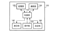
図3は、通信端末100のハードウェア構成を示すブロック図である。通信端末100は、図3に示すように、制御部110と、記憶部120と、通信部130と、表示部140と、操作部150と、測位部160とを備える。制御部110は、CPU(Central Processing Unit)等の演算処理装置と主記憶装置に相当する記憶手段(メインメモリ)とを備え、プログラムを実行することによって通信端末100の各部の動作を制御する。
FIG. 3 is a block diagram illustrating a hardware configuration of the
記憶部120は、フラッシュメモリ等の補助記憶装置に相当する記憶手段を備え、制御部110が処理に用いるデータを記憶する。記憶部120は、サーバ装置200から地図データが送信されると、これを記憶する。なお、記憶部120は、リムーバブルディスク(着脱可能な記憶手段)を含み、ここに地図データを記憶してもよい。この場合、通信端末100は、必ずしもサーバ装置200経由で地図データを取得しなくてもよい。また、記憶部120は、複数の地図データを記憶してもよい。この場合、それぞれの地図データが表すデフォルメ地図は、一部の領域が重複していてもよい。例えば、地図データは、ある大きな区分(地方、州など)でのデフォルメ地図を表すものと、これより小さな地方区分(県、市など)でのデフォルメ地図を表すものとがあってもよい。
The
通信部130は、ネットワークN1を介してサーバ装置200とデータの送受信を行うためのインタフェースである。表示部140は、液晶ディスプレイやその駆動手段を備え、デフォルメ地図等の画像を表示する。操作部150は、キーパッド等の入力手段を備え、ユーザの操作を受け付ける。操作部150は、ユーザの操作を表す操作情報を制御部110に供給する。なお、操作部150は、マウスや、液晶ディスプレイに重ねて設けられたタッチスクリーンであってもよい。
The
測位部160は、位置情報を制御部110に供給する手段である。ここにおいて、位置情報とは、自機の位置(又はこれと同一視し得る位置)を表す情報をいう。位置情報は、本実施形態においては、経緯度座標により表される情報である。測位部160は、位置情報か、あるいは位置情報と対応関係を有する情報を外部から受信する。位置情報を受信する方法は、例えば、GPSである。また、位置情報と対応関係を有する情報は、例えば、地番や住所である。測位部160は、かかる情報を受信する場合には、当該情報と位置情報との対応関係を記憶しておくことにより、位置情報を計算して求めることができる。
The
通信端末100の構成は、以上のとおりである。この構成のもと、通信端末100は、ユーザの操作を受け付け、XY座標が未知である点をデフォルメ地図上に表示させるように制御する。かかる点のことを、以下においては「対象点」という。すなわち、対象点は、表示の対象となる点である。対象点は、例えば、通信端末100の位置、すなわちユーザがそのときにいる位置であるが、必ずしもこれに限定されない。
The configuration of the
対象点は、XY座標が未知であるため、そのままではデフォルメ地図上に表示させることができないものである。そこで、通信端末100は、対象点のXY座標に対応する経緯度座標を取得し、さらに、対象点に近接する基準点の経緯度座標及びXYを用いて、対象点のXY座標を算出する座標変換を行う。
Since the XY coordinates are unknown, the target point cannot be displayed on the deformed map as it is. Therefore, the
図4は、通信端末100が行う座標変換に関する機能的構成を示す機能ブロック図である。通信端末100の制御部110は、プログラムを実行することによって、図4に示す基準点設定部111、座標取得部112、選択部113及び算出部115に相当する機能を実現する。制御部110は、これらの機能を実現することで、本発明に係る座標変換装置として機能する。
FIG. 4 is a functional block diagram illustrating a functional configuration related to coordinate transformation performed by the
基準点設定部111は、デフォルメ地図上に複数の基準点を設定する。基準点設定部111は、通信部130が受信し、又は記憶部120に記憶された地図データを取得し、地図データに含まれる基準点情報に基づいて基準点を設定する。また、基準点設定部111は、ユーザの操作によって基準点を設定することも可能である。
The reference
座標取得部112は、対象点に対応する経緯度座標を取得する。座標取得部112は、例えば、測位部160により供給される位置情報に基づいて経緯度座標を取得する。また、座標取得部112は、ユーザに経緯度座標の入力を要求し、その要求に応じて操作部150から供給される操作情報に基づいて経緯度座標を取得することも可能である。
The coordinate
選択部113は、基準点設定部111により設定された複数の基準点から3個の基準点を選択する。選択部113が選択する基準点は、座標取得部112により取得された経緯度座標、すなわち対象点に近接するものである。ここにおいて、対象点に「近接」するとは、対象点の近くにあることをいうものである。しかし、選択部113は、必ずしも、対象点に近い順に3個の基準点を選択するとは限らない。
The
選択部113は、より詳細には、判定部114に相当する機能を有する。判定部114は、選択部113が選択した3個の基準点の組合せについて、これを座標変換に使用してよいか否かを判定する。判定部114による判定は、あらかじめ決められた所定の条件を用いて行われる。選択部113は、判定部114が座標変換への使用を妥当でないと判定した場合には、直前にした選択を取り消し、他の3個の基準点の組合せを再度選択する。以下においては、選択部113が行う選択のうち、2回目以降の選択のことを「再選択」ともいう。判定部114は、選択された3個の基準点の使用の可否を判定することにより、再選択の要否を判定するものであるともいえる。
In more detail, the
なお、選択部113は、再選択において、それまでに選択した組合せと同一の組合せにならなければ、それまでに選択した基準点と同じものを再度選択してもよい。すなわち、選択部113による再選択は、組合せとして同一にならなければ、取り消した組合せに含まれる基準点が重複することを許容するものである。
Note that the
算出部115は、選択部113により選択された3個の基準点を用いて、対象点のXY座標を算出する。なお、算出部115は、選択部113による選択が取り消された場合、すなわち選択部113により組合せが再選択された場合には、当該再選択された3個の基準点の組合せを用いて対象点のXY座標を算出する。
The
図5は、通信端末100の座標変換に関する動作を示すフローチャートである。通信端末100の制御部110は、まず最初に、複数の基準点を設定する(ステップS1)。このとき、制御部110は、地図データを読み出して基準点情報から基準点を認識するほか、ユーザの操作を受け付け、地図データには存在しない新規な基準点を設定してもよい。例えば、制御部110は、デフォルメ地図を表示部140に表示させ、ユーザにデフォルメ地図上の任意の位置の選択を促すとともに、その位置の経緯度座標を入力させるようにすれば、新規な基準点を設定することが可能である。この場合、経緯度座標は、位置情報から得られてもよい。ユーザは、例えば、自分がデフォルメ地図上の特徴的な場所にいるときに、その位置をクリック等の操作によって選択し、この操作に応じて通信端末100が位置情報を取得するように動作すれば、基準点を新たに設定(追加)することが可能である。
FIG. 5 is a flowchart showing operations related to coordinate transformation of the
次に、制御部110は、対象点の経緯度座標を取得する(ステップS2)。例えば、ユーザがそのときにいる位置を対象点にする場合であれば、制御部110は、測位部160に位置情報を取得させ、取得した位置情報を経緯度座標に用いる。このような経緯度座標の取得方法は、ユーザがそのときにいる位置がデフォルメ地図上のどこに相当するかを知る場合に好適なものである。また、対象点をユーザの位置に限定しない場合であれば、制御部110は、測位部160を用いずに、ユーザに経緯度座標を入力させることで経緯度座標を取得してもよい。このような経緯度座標の取得方法は、あらかじめ経緯度座標がわかっている特定の施設等の位置がデフォルメ地図上のどこに相当するかを知る場合に好適なものである。
Next, the
なお、制御部110は、ステップS1の処理とステップS2の処理の実行順を逆にしてもよい。例えば、対象点をユーザがいる位置以外の位置にする場合であって、対象点の経緯度座標があらかじめわかっている場合などであれば、対象点が基準点よりも先に決まっていてもよい。つまり、基準点と対象点は、どちらが先に決められてもよいものである。
In addition, the
基準点と対象点の相違点は、XY座標が既知か否かにある。経緯度座標とXY座標の双方が既知であり、双方の対応関係が既知な位置が基準点である一方、対象点は、経緯度座標のみが既知であり、XY座標が未知な位置である。なお、対象点が既知の基準点と偶然一致した場合のように、対象点の経緯度座標に対応するXY座標が既知であった場合には、制御部110は、ステップS3及びS4の処理を省略することができる。
The difference between the reference point and the target point is whether or not the XY coordinates are known. While both the longitude and latitude coordinates and the XY coordinates are known and the position where the correspondence between both is known is the reference point, the target point is the position where only the longitude and latitude coordinates are known and the XY coordinates are unknown. When the XY coordinates corresponding to the longitude and latitude coordinates of the target point are known, such as when the target point coincides with a known reference point, the
このようにして対象点及び複数の基準点が決まると、制御部110は、これらの複数の基準点から3個の基準点の組合せを選択する(ステップS3)。ステップS3の処理のことを、以下においては「選択処理」という。選択処理は、詳細には、適当な3個の基準点を選択するとともに、選択した基準点の妥当性を所定の条件を用いて判定し、判定結果が否定的であれば再選択を行う処理である。
When the target point and the plurality of reference points are determined in this way, the
図6は、選択処理を示すフローチャートである。この選択処理において、制御部110は、まず、対象点に近接する3個の基準点を選択する(ステップS31)。なお、ステップS31の処理における「選択」は、いわば仮の選択であり、これが座標の算出に必ず用いられることを意味するものではない。また、ここでいう「近接」は、対象点に近いことを意味するものであるが、対象点に最も近いことを意味するものではない。対象点に近接する基準点は、具体的には、以下のように決められる。
FIG. 6 is a flowchart showing the selection process. In this selection process, the
図7は、対象点に近接する基準点の選択方法を例示する図である。まず、制御部110は、基準の座標系で表される平面(すなわち実地図)に対して、図7(a)に示すように、対象点を中心にして等分割した4区域を定義する。この例は、実地図を東西南北の方向(すなわち、緯度に沿った方向と経度に沿った方向)に等分割するものであるが、分割する方向自体は任意である。次に、制御部110は、これらの4区域から、図7(b)に示すように、対象点に最も近い基準点を1個ずつ抽出する。すなわち、このとき抽出される基準点は、区域毎に1個ずつであり、計4個である。よって、仮に、ある区域にある対象点から2番目に近い基準点と対象点との距離が別の区域にある対象点に最も近い基準点と対象点との距離よりも短いことがあったとしても、前者の基準点が抽出されることはない。
FIG. 7 is a diagram illustrating a method of selecting a reference point close to the target point. First, as shown in FIG. 7A, the
その後、制御部110は、抽出した4個の基準点から、図7(c)に示すように、対象点から最も遠い1個を除外し、残りの3個の基準点を採用する。図7に示す例の場合、基準点Pa、Pb及びPcが採用され、基準点Pdが除外される。この例において、基準点Pa、Pb及びPcは、基準点Paが対象点に最も近く、基準点Pcが対象点から最も遠く、基準点Pbがこれらの中間であるとする。
After that, the
このようにして3個の基準点を選択すると、制御部110は、この3個の基準点の使用の妥当性を判定する(ステップS32)。制御部110は、所定の条件を用いてこの判定を行う。ここにおいて、所定の条件とは、選択された基準点の位置に基づいて定まる図形と対象点の位置の関係を利用したものである。本実施形態の判定は、選択された基準点に基づいて形状が定まる平行四辺形の内部に対象点が含まれるか否かによって行われる。
When three reference points are selected in this way, the
図8は、図7に例示した基準点に基づいて定義される平行四辺形を例示する図である。本実施形態の判定に用いる平行四辺形は、基準点Pa、Pb及びPcを頂点とする第1の平行四辺形を定義した場合に(図8(a)参照)、この第1の平行四辺形を、ある頂点を中心に4倍の大きさになるように拡大した図形である。なお、この拡大の中心となる頂点のことを、以下においては「中心点」ともいう。図8(a)に示す例においては、基準点Paが中心点である。 FIG. 8 is a diagram illustrating a parallelogram defined based on the reference points illustrated in FIG. Parallelogram used to determine the present embodiment, (see FIG. 8 (a)) in the case where the reference point P a, a P b and P c defines the first parallelogram vertex, the first This is a figure obtained by enlarging a parallelogram so that it is four times as large as a certain vertex. In addition, the vertex which becomes the center of this expansion is also called "center point" below. In the example shown in FIG. 8 (a), the reference point P a is the center point.
本実施形態の判定に用いる平行四辺形は、図8(b)に示す点P1、P2、P3及びP4を頂点をする平行四辺形である。本実施形態の判定に用いる平行四辺形は、中心点を図形の重心とし、基準点を辺の中点(又は頂点)に含み得るものである。また、上述した第1の平行四辺形は、基準点Pa、Pb、Pc及び点P3を頂点とする平行四辺形である。 The parallelogram used in the determination of the present embodiment is a parallelogram having apexes at points P 1 , P 2 , P 3 and P 4 shown in FIG. The parallelogram used in the determination of this embodiment can include the center point as the center of gravity of the figure and the reference point at the midpoint (or vertex) of the side. The first parallelogram described above, the reference point P a, P b, the P c and the point P 3 is a parallelogram having vertices.
制御部110は、実地図の座標系において、対象点が所定の平行四辺形(図8の平行四辺形P1P2P3P4)の内部(内側)に含まれるか否かを判定し、これに対象点が含まれていれば、この場合の基準点Pa、Pb及びPcを座標の算出に用いるものとして採用し(ステップS34)、選択処理を終える。一方、制御部110は、対象点が所定の平行四辺形の内部に含まれなければ、基準点を再選択する(ステップS33)。基準点(及びその組合せ)の再選択には、ステップS31の処理の際に抽出された4個の基準点を用いることができる。
The
図9は、基準点の組合せの再選択方法を例示する表である。図9は、図7に例示した基準点を用いて再選択方法を説明するためのものである。制御部110は、図9に示す順番に従って選択及び判定を行い、判定が否定的(使用が不適)であれば、次の選択及び判定を行う、という動作を繰り返す。すなわち、この再選択方法は、4個ある基準点から3個を選ぶ組合せによる選択を、中心点を変えながら繰り返すものである。よって、この場合の基準点の選択方法は、中心点以外の3個の基準点から2個の基準点を選ぶ組合せ(3C2=3)を4通りの中心点について行うものであるから、全部で12(=3×4)通りである。なお、中心点は、望ましくは、対象点により近い基準点から順番に選択される。
FIG. 9 is a table illustrating a method for reselecting a combination of reference points. FIG. 9 is a diagram for explaining a reselection method using the reference points illustrated in FIG. The
制御部110は、図9に例示した再選択を繰り返しても妥当な組合せが得られない場合には、座標変換が不能である旨をユーザに報知するか、あるいは、ステップS31の処理における「近接」の範囲を広げて(緩和して)基準点をさらに選択し直す。具体的には、制御部110は、等分割した4区域から、対象点に最も近い基準点ではなく、対象点に2番目に近い基準点を1個ずつ抽出し、ここから3個の基準点を選択することが可能である。
The
適当な3個の基準点が選択されると、制御部110は、これらの基準点の座標を用いて対象点のXY座標を算出する(ステップS4)。座標の算出には、周知の方法を用いてよいが、例えば、以下のとおりである。ここにおいて、対象点をPとし、3個の基準点をA、B及びCとする。また、点Pの緯度、経度、x座標、y座標を、それぞれ、latP、lngP、xP、yPとする(その他の点についても同様とする。)。なお、図10は、対象点Pと基準点A、B及びCを例示する図である。
When appropriate three reference points are selected, the
いま、対象点Pと基準点A、B及びCの経緯度座標には、次の(1)、(2)式に示す関係が成り立つ。ここにおいて、m及びnは、適当な係数である。
lngP - lngA = n(lngB - lngA) + m(lngC - lngA) …(1)
latP - latA = n(latB - latA) + m(latC - latA) …(2)
Now, the relationship shown in the following equations (1) and (2) is established between the longitude and latitude coordinates of the target point P and the reference points A, B, and C. Here, m and n are appropriate coefficients.
lngP-lngA = n (lngB-lngA) + m (lngC-lngA) (1)
latP-latA = n (latB-latA) + m (latC-latA) ... (2)
ここにおいて、m及びn以外の値は既知である。よって、上述した(1)、(2)式の連立方程式を解くことにより、m及びnの値を特定することが可能である。m及びnの値は、対象点Pが平行四辺形の内部に含まれるものであれば、いずれも1以下である。なお、m及びnの値がともに1であれば、対象点Pは、平行四辺形の頂点と一致する。つまり、このとき、基準点A、B及びCによって定義される平行四辺形の相似形である平行四辺形ADPEを考えた場合、AC:AE=1:mであり、AB:AD=1:nである。 Here, values other than m and n are known. Therefore, it is possible to specify the values of m and n by solving the simultaneous equations (1) and (2) described above. The values of m and n are both 1 or less as long as the target point P is included in the parallelogram. If the values of m and n are both 1, the target point P coincides with the vertex of the parallelogram. That is, at this time, when considering the parallelogram ADPE which is a similar shape of the parallelogram defined by the reference points A, B and C, AC: AE = 1: m and AB: AD = 1: n. It is.
m及びnの値が特定できると、XY座標について、上述した(1)、(2)式と同様の要領で次の(3)、(4)式に示す関係が成り立つ。
xP = {n(xB - xA) + m(xC - xA)} + xA …(3)
yP = {n(yB - yA) + m(yC - yA)} + yA …(4)
(3)、(4)式の右辺は、いずれも既知の値で構成されている。よって、(3)、(4)式を解くことにより、xP及びyP、すなわち対象点のXY座標を特定することが可能である。
If the values of m and n can be specified, the relationship shown in the following formulas (3) and (4) is established in the same manner as the formulas (1) and (2) described above for the XY coordinates.
xP = {n (xB-xA) + m (xC-xA)} + xA (3)
yP = {n (yB-yA) + m (yC-yA)} + yA (4)
The right sides of the expressions (3) and (4) are both configured with known values. Therefore, xP and yP, that is, the XY coordinates of the target point can be specified by solving equations (3) and (4).
通信端末100は、以上のように座標変換を行うことで、選択した基準点の適否を判定し、必要に応じて基準点を再選択することが可能である。このようにすることで、通信端末100は、より適当な基準点、すなわちより誤差が生じにくい基準点を用いて座標変換を行うことが可能である。基準点の絶対数が少ない場合に、基準点の選択が適当でないと、誤差が大きくなる可能性が高くなる。よって、本実施形態のように基準点の適否を判定することは、座標変換の誤差を少なくすることに寄与し得る。
The
本実施形態のように、対象点が平行四辺形の内部に含まれるように基準点を選択した場合には、そうでない場合に比べ、誤差が小さくなる可能性が高くなる。なぜならば、対象点が平行四辺形の内部に含まれていれば、対象点について生じ得る誤差は、基準点に生じる誤差以下に収まる可能性が高いからである(ただし、デフォルメ地図の変形が著しい場合などは、この限りではない。)。 When the reference point is selected so that the target point is included in the parallelogram as in the present embodiment, there is a higher possibility that the error is smaller than when the reference point is not. This is because if the target point is included in the parallelogram, the error that can occur in the target point is likely to be less than or equal to the error that occurs in the reference point (however, deformation of the deformed map is significant). This does not apply to cases).
なお、通信端末100は、上述した説明と同様の要領で、デフォルメ地図の座標系から実地図の座標系への座標変換、すなわち座標変換の逆変換も行うことが可能である。つまり、本実施形態においては、デフォルメ地図の座標系と実地図の座標系のいずれもが基準の座標系となり得る。換言すれば、本実施形態における基準の座標系は、対象点の座標が既知である方の座標系であるともいえる。要するに、本発明に係る「第1の座標系」は、デフォルメ地図の座標系と実地図の座標系のいずれか一方がこれに該当し、本発明に係る「第2の座標系」は、デフォルメ地図の座標系と実地図の座標系のうちの第1の座標系でない方がこれに該当する、ということである。
The
[変形例]
上述した実施形態は、本発明の実施の一例にすぎない。本発明は、上述した実施形態に対して以下の変形を適用した態様で実施することも可能である。なお、以下に示す変形例は、必要に応じて、各々を適当に組み合わせて実施されてもよいものである。
[Modification]
The above-described embodiment is merely an example of the implementation of the present invention. The present invention can also be implemented in a mode in which the following modifications are applied to the above-described embodiments. In addition, the modification shown below may be implemented combining each suitably as needed.
(変形例1)
本発明における基準点の判定方法は、対象点が上述した第1の平行四辺形に含まれることを条件に用いてもよいものである。この場合、上述した実施形態の判定方法に比べ、平行四辺形の大きさが4分の1になるため、座標変換の誤差をより少なくする可能性を高めることができる。一方で、平行四辺形の大きさが小さくなることから、再選択の回数が大きくなる可能性が増大するともいえる。したがって、判定に用いる条件(図形の大きさ)は、座標変換の精度と処理の簡便さとの間に生じるトレードオフを考慮し、適当に定めればよいものである。
(Modification 1)
The reference point determination method in the present invention may be used on condition that the target point is included in the first parallelogram described above. In this case, compared to the determination method of the above-described embodiment, the size of the parallelogram is ¼, so that it is possible to increase the possibility of reducing errors in coordinate conversion. On the other hand, since the size of the parallelogram is reduced, it can be said that the possibility of increasing the number of reselections increases. Therefore, the condition (size of the figure) used for the determination may be determined appropriately in consideration of a trade-off that occurs between the accuracy of coordinate conversion and the simplicity of processing.
また、本発明において、基準点の判定に用いる図形は、必ずしも平行四辺形でなくてもよい。基準点の判定に用いる図形は、例えば、3個の基準点を頂点とする三角形やその対称形であってもよいし、平行四辺形以外の四角形であってもよい。
図11は、基準点の判定に用いる図形を例示する図である。図11(a)は、3個の基準点を頂点とする三角形を示し、図11(b)は、図11(a)に示す三角形の対称形であり、当該三角形の1辺をに関して対称(線対称)な四角形を示す例である。また、図11(c)は、3個の基準点を辺又は頂点に含む長方形を示す例である。
In the present invention, the figure used for determining the reference point is not necessarily a parallelogram. The figure used for the determination of the reference point may be, for example, a triangle having three reference points as vertices or a symmetrical shape thereof, or a rectangle other than a parallelogram.
FIG. 11 is a diagram illustrating a figure used for determining the reference point. FIG. 11A shows a triangle having three reference points as vertices, and FIG. 11B shows a symmetrical shape of the triangle shown in FIG. 11A, which is symmetrical with respect to one side of the triangle ( This is an example showing a line-symmetric quadrilateral. FIG. 11C shows an example of a rectangle including three reference points at sides or vertices.
(変形例2)
本発明において、選択処理における平面の分割の数は、「4」に限定されない。本発明において、基準の座標系で表される平面を分割することの目的は、基準点が対象点からみて特定の方向に集中しないようにすることにあり、基準点を適度に分散させるためである。よって、平面の分割方法は、かかる目的を達成できるのであれば、平面を3区域に分割するものであってもよく、5以上の区域に分割するものであってもよいし、分割の態様を等分割に限定する必要もない。
(Modification 2)
In the present invention, the number of plane divisions in the selection process is not limited to “4”. In the present invention, the purpose of dividing the plane represented by the reference coordinate system is to prevent the reference points from being concentrated in a specific direction when viewed from the target point, in order to appropriately distribute the reference points. is there. Therefore, as long as such a purpose can be achieved, the plane dividing method may divide the plane into three areas, or may divide the plane into five or more areas. It is not necessary to limit to equal division.
例えば、基準の座標系で表される平面を3区域に等分割した場合、選択処理は、それぞれの区域から基準点を1個ずつ抽出するものになる。この場合、基準点の組合せを変えることはできないが、上述した中心点を変えることは可能である。よって、この場合であっても、再選択を行うことは可能である。また、基準の座標系で表される平面を5以上の区域に分割した場合、選択処理は、各々の区域から1個ずつ基準点を抽出し、抽出した複数個の基準点から3個の基準点を選択するものであってもよい。 For example, when a plane represented by the reference coordinate system is equally divided into three areas, the selection process extracts one reference point from each area. In this case, the combination of the reference points cannot be changed, but the above-described center point can be changed. Therefore, even in this case, reselection can be performed. In addition, when the plane represented by the reference coordinate system is divided into five or more areas, the selection process extracts one reference point from each area, and three reference points from the extracted plurality of reference points. A point may be selected.
また、本発明は、基準点が適度に分散していることを判定の条件に用いてもよいものである。つまり、本発明の選択処理は、あらかじめ分割される区域が決まっているのではなく、対象点に近接する3個の基準点を選択した後に、それぞれの基準点が分割された区域のいずれにも2個以上含まれない(すなわち1個ないし0個である)場合に、これらの基準点の使用を妥当であると判定するものであってもよい。 Further, in the present invention, it may be used as a determination condition that the reference points are appropriately dispersed. In other words, the selection process of the present invention does not determine the area to be divided in advance, but selects three reference points close to the target point and then selects any of the areas into which each reference point is divided. When two or more are not included (that is, 1 to 0), it may be determined that the use of these reference points is appropriate.
(変形例3)
本発明は、実地図やデフォルメ地図を複数のユーザが共有し、各々のユーザが基準点やコンテンツ情報を追加するものであってもよい。このようにすれば、デフォルメ地図の基準点を増やすことをより容易にすることができる。
また、上述した実施形態は、本発明を2次元の地図に適用したものであるが、本発明は、3次元的な立体の地図に対しても適用可能なものである。
(Modification 3)
In the present invention, a real map or a deformed map may be shared by a plurality of users, and each user may add a reference point or content information. This makes it easier to increase the reference points of the deformed map.
Moreover, although embodiment mentioned above applies this invention to a two-dimensional map, this invention is applicable also to a three-dimensional solid map.
本発明は、通信端末やこれを含む地図表示システムのみならず、これらを実現するための方法や、図4に示した機能をコンピュータに実現させるためのプログラムとしても把握されるものである。かかるプログラムは、これを記憶させた光ディスク等の記録媒体の形態で提供されたり、インターネット等のネットワークを介して、コンピュータにダウンロードさせ、これをインストールして利用可能にするなどの形態で提供されたりすることができるものである。 The present invention is grasped not only as a communication terminal and a map display system including the communication terminal, but also as a method for realizing them and a program for causing a computer to realize the functions shown in FIG. Such a program may be provided in the form of a recording medium such as an optical disk storing the program, or may be provided in the form of being downloaded to a computer via a network such as the Internet, and installed and made available. Is something that can be done.
10…地図表示システム、100…通信端末、110…制御部、111…基準点設定部、112…座標取得部、113…選択部、114…判定部、115…算出部、120…記憶部、130…通信部、140…表示部、150…操作部、160…測位部、200…サーバ装置
DESCRIPTION OF
Claims (9)
前記地図上の前記第2の座標系の座標が未知である対象点に対応する前記第1の座標系の座標を取得する座標取得部と、
前記基準点設定部により設定された複数の基準点から、前記第1の座標系の座標が前記座標取得部により取得された座標に近接する3個の基準点を選択する選択部と、
前記選択部により選択された3個の基準点の前記第1の座標系及び前記第2の座標系の座標を用いて、前記対象点の前記第2の座標系の座標を算出する算出部とを備え、
前記選択部は、3個の基準点の組合せが所定の条件を満たさない場合に、他の3個の基準点の組合せを再選択し、
前記算出部は、前記選択部により前記組合せが再選択された場合に、当該再選択された3個の基準点を用いる
ことを特徴とする座標変換装置。 A plurality of criteria whose correspondences between the coordinates of the first coordinate system and the coordinates of the second coordinate system are known on a map described in a second coordinate system different from the first coordinate system of the reference A reference point setting unit for setting points;
A coordinate acquisition unit that acquires coordinates of the first coordinate system corresponding to a target point whose coordinates of the second coordinate system on the map are unknown;
A selection unit that selects, from a plurality of reference points set by the reference point setting unit, three reference points whose coordinates in the first coordinate system are close to the coordinates acquired by the coordinate acquisition unit;
A calculation unit for calculating coordinates of the second coordinate system of the target point using the coordinates of the first coordinate system and the second coordinate system of the three reference points selected by the selection unit; With
The selection unit re-selects the other three reference point combinations when the combination of the three reference points does not satisfy the predetermined condition,
The calculation unit uses the three reselected reference points when the combination is reselected by the selection unit.
前記第1の座標系で表される平面において、前記3個の基準点を頂点とする平行四辺形に前記対象点が含まれることを前記条件に用いて前記再選択の要否を判定する判定部を有する
ことを特徴とする請求項1に記載の座標変換装置。 The selection unit includes:
Judgment for determining whether the reselection is necessary using the condition that the target point is included in a parallelogram having the three reference points as vertices in the plane represented by the first coordinate system. The coordinate conversion device according to claim 1, further comprising a unit.
前記第1の座標系で表される平面において、前記3個の基準点の1個を重心とし、他の2個を辺の中点とする平行四辺形に前記対象点が含まれることを前記条件に用いて前記再選択の要否を判定する判定部を有する
ことを特徴とする請求項1に記載の座標変換装置。 The selection unit includes:
In the plane represented by the first coordinate system, the target point is included in a parallelogram having one of the three reference points as a center of gravity and the other two as midpoints of the sides. The coordinate conversion apparatus according to claim 1, further comprising a determination unit that determines whether or not the reselection is necessary using a condition.
前記第1の座標系で表される平面において、前記3個の基準点を頂点又は辺に含む四角形に前記対象点が含まれることを前記条件に用いて前記再選択の要否を判定する判定部を有する
ことを特徴とする請求項1に記載の座標変換装置。 The selection unit includes:
Judgment for determining whether or not the reselection is necessary using the condition that the target point is included in a quadrangle including the three reference points at the apex or the side in the plane represented by the first coordinate system. The coordinate conversion device according to claim 1, further comprising a unit.
前記第1の座標系で表される平面を前記対象点を中心に4以上の区域に分割した場合に、前記対象点に最も近い前記基準点を当該分割された区域から1個ずつ抽出し、当該抽出した基準点から前記組合せを選択及び再選択する
ことを特徴とする請求項1ないし3のいずれかに記載の座標変換装置。 The selection unit includes:
When the plane represented by the first coordinate system is divided into four or more areas around the target point, the reference points closest to the target point are extracted one by one from the divided area, The coordinate transformation device according to any one of claims 1 to 3, wherein the combination is selected and reselected from the extracted reference points.
前記選択部は、
前記組合せとして、前記分割された4区域から抽出された4個の基準点から3個の基準点を選ぶ組合せを用いる
ことを特徴とする請求項5に記載の座標変換装置。 The number of the divisions is 4,
The selection unit includes:
The coordinate transformation device according to claim 5, wherein a combination of selecting three reference points from four reference points extracted from the four divided areas is used as the combination.
前記第1の座標系で表される平面を前記対象点を中心に3以上の区域に分割した場合に、前記3個の基準点が当該分割された区域のいずれかにも2個以上含まれないことを前記条件に用いて前記再選択の要否を判定する判定部を有する
ことを特徴とする請求項1ないし6のいずれかに記載の座標変換装置。 The selection unit includes:
When the plane represented by the first coordinate system is divided into three or more areas around the target point, two or more of the three reference points are included in any of the divided areas. The coordinate conversion apparatus according to claim 1, further comprising: a determination unit that determines whether or not the reselection is necessary using the absence as the condition.
前記地図上の前記第2の座標系の座標が未知である対象点に対応する前記第1の座標系の座標を取得する第2ステップと、
前記第1ステップにおいて設定された複数の基準点から、前記第1の座標系の座標が前記第2ステップにおいて取得された座標に近接する3個の基準点を選択する第3ステップと、
前記第3ステップにおいて選択された3個の基準点の前記第1の座標系及び前記第2の座標系の座標を用いて、前記対象点の前記第2の座標系の座標を算出する第4ステップとを実行し、
前記第3ステップにおいて、3個の基準点の組合せが所定の条件を満たさない場合に、他の3個の基準点の組合せを再選択し、
前記第3ステップにおいて前記組合せが再選択された場合に、前記第4ステップにおいて当該再選択された3個の基準点を用いる
ことを特徴とする座標変換方法。 A plurality of criteria whose correspondences between the coordinates of the first coordinate system and the coordinates of the second coordinate system are known on a map described in a second coordinate system different from the first coordinate system of the reference A first step of setting points;
A second step of obtaining coordinates of the first coordinate system corresponding to a target point whose coordinates of the second coordinate system on the map are unknown;
A third step of selecting, from a plurality of reference points set in the first step, three reference points whose coordinates of the first coordinate system are close to the coordinates acquired in the second step;
4th which calculates the coordinate of the said 2nd coordinate system of the said object point using the coordinate of the said 1st coordinate system of the three reference points selected in the said 3rd step, and the said 2nd coordinate system. Perform steps and
In the third step, when the combination of the three reference points does not satisfy the predetermined condition, the other three reference point combinations are reselected,
When the combination is reselected in the third step, the three reference points reselected in the fourth step are used.
基準の第1の座標系と異なる第2の座標系で記述された地図上に、前記第1の座標系の座標と前記第2の座標系の座標との対応関係が既知である複数の基準点を設定する第1ステップと、
前記地図上の前記第2の座標系の座標が未知である対象点に対応する前記第1の座標系の座標を取得する第2ステップと、
前記第1ステップにおいて設定された複数の基準点から、前記第1の座標系の座標が前記第2ステップにおいて取得された座標に近接する3個の基準点を選択する第3ステップと、
前記第3ステップにおいて選択された3個の基準点の前記第1の座標系及び前記第2の座標系の座標を用いて、前記対象点の前記第2の座標系の座標を算出する第4ステップとを実行させるためのプログラムであって、
前記第3ステップにおいて、3個の基準点の組合せが所定の条件を満たさない場合に、他の3個の基準点の組合せを再選択し、
前記第3ステップにおいて前記組合せが再選択された場合に、当該再選択された3個の基準点を前記第4ステップにおいて用いる
ことを特徴とするプログラム。 On the computer,
A plurality of criteria whose correspondences between the coordinates of the first coordinate system and the coordinates of the second coordinate system are known on a map described in a second coordinate system different from the first coordinate system of the reference A first step of setting points;
A second step of obtaining coordinates of the first coordinate system corresponding to a target point whose coordinates of the second coordinate system on the map are unknown;
A third step of selecting, from a plurality of reference points set in the first step, three reference points whose coordinates of the first coordinate system are close to the coordinates acquired in the second step;
4th which calculates the coordinate of the said 2nd coordinate system of the said object point using the coordinate of the said 1st coordinate system of the three reference points selected in the said 3rd step, and the said 2nd coordinate system. A program for executing steps,
In the third step, when the combination of the three reference points does not satisfy the predetermined condition, the other three reference point combinations are reselected,
When the combination is reselected in the third step, the three reselected reference points are used in the fourth step.
Priority Applications (1)
| Application Number | Priority Date | Filing Date | Title |
|---|---|---|---|
| JP2010101015A JP5746831B2 (en) | 2010-04-26 | 2010-04-26 | Coordinate transformation device, coordinate transformation method and program |
Applications Claiming Priority (1)
| Application Number | Priority Date | Filing Date | Title |
|---|---|---|---|
| JP2010101015A JP5746831B2 (en) | 2010-04-26 | 2010-04-26 | Coordinate transformation device, coordinate transformation method and program |
Publications (2)
| Publication Number | Publication Date |
|---|---|
| JP2011232444A true JP2011232444A (en) | 2011-11-17 |
| JP5746831B2 JP5746831B2 (en) | 2015-07-08 |
Family
ID=45321828
Family Applications (1)
| Application Number | Title | Priority Date | Filing Date |
|---|---|---|---|
| JP2010101015A Expired - Fee Related JP5746831B2 (en) | 2010-04-26 | 2010-04-26 | Coordinate transformation device, coordinate transformation method and program |
Country Status (1)
| Country | Link |
|---|---|
| JP (1) | JP5746831B2 (en) |
Cited By (7)
| Publication number | Priority date | Publication date | Assignee | Title |
|---|---|---|---|---|
| JP2013109049A (en) * | 2011-11-18 | 2013-06-06 | Advanced Telecommunication Research Institute International | Map information system and terminal device |
| JP2013228566A (en) * | 2012-04-26 | 2013-11-07 | Mic Ware:Kk | Map information processing unit, map information processing method and program |
| JP2014035515A (en) * | 2012-08-10 | 2014-02-24 | Science Impact Co Ltd | Coordinate value conversion device, coordinate value conversion method, and coordinate value conversion program |
| JP2015099330A (en) * | 2013-11-20 | 2015-05-28 | ヤフー株式会社 | Information processing apparatus, display control program, and display control method |
| JP2016061621A (en) * | 2014-09-17 | 2016-04-25 | 株式会社インテック | Navigation device, navigation method and navigation program |
| CN109827573A (en) * | 2017-11-23 | 2019-05-31 | 中国移动通信集团上海有限公司 | Judgment method, system and application of coordinate system |
| CN111680116A (en) * | 2020-05-14 | 2020-09-18 | 上海移远通信技术股份有限公司 | Map-based position information display method, system, medium, and electronic device |
Families Citing this family (1)
| Publication number | Priority date | Publication date | Assignee | Title |
|---|---|---|---|---|
| CN105550454A (en) * | 2015-12-21 | 2016-05-04 | 安徽理工大学 | JAVA coordinate converter-based measurement method |
Citations (7)
| Publication number | Priority date | Publication date | Assignee | Title |
|---|---|---|---|---|
| JP2001059734A (en) * | 1999-08-23 | 2001-03-06 | Equos Research Co Ltd | Navigation device |
| JP2003130680A (en) * | 2001-10-29 | 2003-05-08 | Kddi Corp | Map display terminal, map display device, wireless terminal thereof, and map server |
| JP2003187241A (en) * | 2001-12-13 | 2003-07-04 | Mitsuhiro Tsuda | Method for aligning position of images |
| JP2004085779A (en) * | 2002-08-26 | 2004-03-18 | Keiko Nakayama | Method and computer program for drawing spatial information on digital map |
| US20070176932A1 (en) * | 2006-02-01 | 2007-08-02 | Microsoft Corporation | Design of arbitrary linear and non-linear maps |
| JP2008191075A (en) * | 2007-02-07 | 2008-08-21 | Alps Sha:Kk | Position specifying method for deformation map, position specifying system for the deformation map, position specifying method for measurement map, and position specifying system for measurement map |
| JP2010017834A (en) * | 2008-07-14 | 2010-01-28 | Central Motor Co Ltd | Clamping mechanism for material hand |
-
2010
- 2010-04-26 JP JP2010101015A patent/JP5746831B2/en not_active Expired - Fee Related
Patent Citations (7)
| Publication number | Priority date | Publication date | Assignee | Title |
|---|---|---|---|---|
| JP2001059734A (en) * | 1999-08-23 | 2001-03-06 | Equos Research Co Ltd | Navigation device |
| JP2003130680A (en) * | 2001-10-29 | 2003-05-08 | Kddi Corp | Map display terminal, map display device, wireless terminal thereof, and map server |
| JP2003187241A (en) * | 2001-12-13 | 2003-07-04 | Mitsuhiro Tsuda | Method for aligning position of images |
| JP2004085779A (en) * | 2002-08-26 | 2004-03-18 | Keiko Nakayama | Method and computer program for drawing spatial information on digital map |
| US20070176932A1 (en) * | 2006-02-01 | 2007-08-02 | Microsoft Corporation | Design of arbitrary linear and non-linear maps |
| JP2008191075A (en) * | 2007-02-07 | 2008-08-21 | Alps Sha:Kk | Position specifying method for deformation map, position specifying system for the deformation map, position specifying method for measurement map, and position specifying system for measurement map |
| JP2010017834A (en) * | 2008-07-14 | 2010-01-28 | Central Motor Co Ltd | Clamping mechanism for material hand |
Cited By (9)
| Publication number | Priority date | Publication date | Assignee | Title |
|---|---|---|---|---|
| JP2013109049A (en) * | 2011-11-18 | 2013-06-06 | Advanced Telecommunication Research Institute International | Map information system and terminal device |
| JP2013228566A (en) * | 2012-04-26 | 2013-11-07 | Mic Ware:Kk | Map information processing unit, map information processing method and program |
| JP2014035515A (en) * | 2012-08-10 | 2014-02-24 | Science Impact Co Ltd | Coordinate value conversion device, coordinate value conversion method, and coordinate value conversion program |
| JP2015099330A (en) * | 2013-11-20 | 2015-05-28 | ヤフー株式会社 | Information processing apparatus, display control program, and display control method |
| JP2016061621A (en) * | 2014-09-17 | 2016-04-25 | 株式会社インテック | Navigation device, navigation method and navigation program |
| CN109827573A (en) * | 2017-11-23 | 2019-05-31 | 中国移动通信集团上海有限公司 | Judgment method, system and application of coordinate system |
| CN109827573B (en) * | 2017-11-23 | 2020-11-13 | 中国移动通信集团上海有限公司 | Judgment method, system and application of coordinate system |
| CN111680116A (en) * | 2020-05-14 | 2020-09-18 | 上海移远通信技术股份有限公司 | Map-based position information display method, system, medium, and electronic device |
| CN111680116B (en) * | 2020-05-14 | 2023-06-09 | 广东移远通信技术有限公司 | Map-based position information display method, system, medium and electronic equipment |
Also Published As
| Publication number | Publication date |
|---|---|
| JP5746831B2 (en) | 2015-07-08 |
Similar Documents
| Publication | Publication Date | Title |
|---|---|---|
| JP5746831B2 (en) | Coordinate transformation device, coordinate transformation method and program | |
| CN110347769B (en) | Processing method, device, equipment and storage medium for multi-level map tiles | |
| JP2018119984A (en) | Navigation directions between automatically determined starting points and selected destinations | |
| KR20170046675A (en) | Providing in-navigation search results that reduce route disruption | |
| JP5312815B2 (en) | Map enlargement display device | |
| KR20170080315A (en) | Map processing method based on multi-scale model for building object | |
| JP5705793B2 (en) | Augmented reality display device, augmented reality display system, augmented reality display method, and augmented reality display program | |
| JP7086180B2 (en) | Dynamic styling of digital maps | |
| JP5907794B2 (en) | Map information processing apparatus, map information processing method, and program | |
| JP6174939B2 (en) | Map note processing device, map note processing method, and map information providing device | |
| JP2009069483A (en) | Display information processing device | |
| JP2015219185A (en) | Path output device and path output method | |
| JP5735939B2 (en) | Map display device, map display method, and map display program | |
| KR101070779B1 (en) | Mapping system and method for the panorama photos of a map information | |
| JP2010151539A (en) | Map information processing device, method for processing map information, and program | |
| JP2004062602A (en) | Device and method for displaying image | |
| JP6168844B2 (en) | Information processing apparatus, information processing method, and program | |
| JP2011008019A (en) | Controller, projector, control method, projection method, control program, projection program, and recording medium | |
| JP2016071786A (en) | Geographic information vectorization supporting system and geographic information vectorization support method | |
| JP6383693B2 (en) | Information processing apparatus, program, and information processing method | |
| JP7463267B2 (en) | Information processing device, method for displaying map images of remote islands, and computer program | |
| JP2013061510A (en) | Map note processing apparatus and map note processing method | |
| JP6575888B1 (en) | Regional information display system | |
| JP2007271403A (en) | Route information display terminal, route information server, route information system and route information program | |
| JP6016765B2 (en) | 3D map display system and synthetic texture generation apparatus |
Legal Events
| Date | Code | Title | Description |
|---|---|---|---|
| A621 | Written request for application examination |
Free format text: JAPANESE INTERMEDIATE CODE: A621 Effective date: 20130214 |
|
| A977 | Report on retrieval |
Free format text: JAPANESE INTERMEDIATE CODE: A971007 Effective date: 20130705 |
|
| A131 | Notification of reasons for refusal |
Free format text: JAPANESE INTERMEDIATE CODE: A131 Effective date: 20140520 |
|
| A521 | Written amendment |
Free format text: JAPANESE INTERMEDIATE CODE: A523 Effective date: 20140714 |
|
| A131 | Notification of reasons for refusal |
Free format text: JAPANESE INTERMEDIATE CODE: A131 Effective date: 20140812 |
|
| A521 | Written amendment |
Free format text: JAPANESE INTERMEDIATE CODE: A523 Effective date: 20141010 |
|
| TRDD | Decision of grant or rejection written | ||
| A01 | Written decision to grant a patent or to grant a registration (utility model) |
Free format text: JAPANESE INTERMEDIATE CODE: A01 Effective date: 20150421 |
|
| A61 | First payment of annual fees (during grant procedure) |
Free format text: JAPANESE INTERMEDIATE CODE: A61 Effective date: 20150511 |
|
| R150 | Certificate of patent or registration of utility model |
Ref document number: 5746831 Country of ref document: JP Free format text: JAPANESE INTERMEDIATE CODE: R150 |
|
| R250 | Receipt of annual fees |
Free format text: JAPANESE INTERMEDIATE CODE: R250 |
|
| LAPS | Cancellation because of no payment of annual fees |