JP2011181129A - Semiconductor integrated circuit and disk drive recording/reproducing device using the same - Google Patents
Semiconductor integrated circuit and disk drive recording/reproducing device using the same Download PDFInfo
- Publication number
- JP2011181129A JP2011181129A JP2010042589A JP2010042589A JP2011181129A JP 2011181129 A JP2011181129 A JP 2011181129A JP 2010042589 A JP2010042589 A JP 2010042589A JP 2010042589 A JP2010042589 A JP 2010042589A JP 2011181129 A JP2011181129 A JP 2011181129A
- Authority
- JP
- Japan
- Prior art keywords
- signal
- servo
- control
- data
- buffer
- Prior art date
- Legal status (The legal status is an assumption and is not a legal conclusion. Google has not performed a legal analysis and makes no representation as to the accuracy of the status listed.)
- Withdrawn
Links
Images


Classifications
-
- G—PHYSICS
- G11—INFORMATION STORAGE
- G11B—INFORMATION STORAGE BASED ON RELATIVE MOVEMENT BETWEEN RECORD CARRIER AND TRANSDUCER
- G11B19/00—Driving, starting, stopping record carriers not specifically of filamentary or web form, or of supports therefor; Control thereof; Control of operating function ; Driving both disc and head
- G11B19/02—Control of operating function, e.g. switching from recording to reproducing
- G11B19/04—Arrangements for preventing, inhibiting, or warning against double recording on the same blank or against other recording or reproducing malfunctions
- G11B19/048—Testing of disk drives, e.g. to detect defects or prevent sudden failure
Landscapes
- Optical Recording Or Reproduction (AREA)
- Signal Processing For Digital Recording And Reproducing (AREA)
Abstract
【課題】ディスクの読み出しデータとサーボ制御部のサーボ信号との両者から総合的な評価を可能とする。
【解決手段】ディスクドライブ記録再生装置0001に搭載可能な半導体集積回路LSIは、ピックアップから読み出されるRF信号の信号処理部0107、ピックアップから読み出されるサーボ誤差信号に応答するサーボ制御部0106、メモリ制御部0108、外部インターフェース0110を含む。メモリ制御部0108に読み出しデータA002とサーボ信号A001とが供給され、メモリ制御部0108は読み出しデータA002とサーボ信号A001とを時分割処理によってバッファメモリ0109に格納する。バッファメモリに格納された読み出しデータA002とサーボ信号A001とはメモリ制御部0108によって外部インターフェース0110を介して外部装置0002に転送可能とされる。
【選択図】図1An object of the present invention is to enable comprehensive evaluation from both read data of a disk and a servo signal of a servo control unit.
A semiconductor integrated circuit LSI that can be mounted on a disk drive recording / reproducing apparatus 0001 includes a signal processing unit 0107 for an RF signal read from a pickup, a servo control unit 0106 for responding to a servo error signal read from the pickup, and a memory control unit. 0108, including an external interface 0110. Read data A002 and servo signal A001 are supplied to the memory control unit 0108, and the memory control unit 0108 stores the read data A002 and servo signal A001 in the buffer memory 0109 by time division processing. The read data A002 and servo signal A001 stored in the buffer memory can be transferred to the external device 0002 via the external interface 0110 by the memory control unit 0108.
[Selection] Figure 1
Description
本発明は、半導体集積回路およびそれを使用したディスクドライブ記録再生装置に関し、特にディスクの読み出しデータとサーボ制御部の内部信号との両者から総合的な評価を可能とするのに有効な技術に関するものである。 The present invention relates to a semiconductor integrated circuit and a disk drive recording / reproducing apparatus using the same, and more particularly to a technique effective for enabling comprehensive evaluation from both read data of a disk and an internal signal of a servo control unit. It is.
CD(Compact Disk)、DVD(Digital Versatile Disk)、BD(Blu-Ray Disk)等の光ディスクの情報を記録・再生する光ディスクドライブ記録再生装置では、光ピックアップからの放射レーザ光を光ディスク記録面に照射して、その反射光を光ピックアップによって検出してRFアナログ再生信号が生成される。このような光ディスクドライブ記録再生装置の記録・再生には、スピンドル駆動、トラッキング制御、フォーカス制御等の種々の制御が必要である。この種々の制御のためには、光ピックアップで検出されたRFアナログ検出信号は半導体集積回路のA/D変換器によってデジタル信号に変換され、このデジタル信号は半導体集積回路内部でデジタル信号処理される。 In an optical disk drive recording / reproducing apparatus for recording / reproducing information on an optical disk such as a CD (Compact Disk), DVD (Digital Versatile Disk), BD (Blu-Ray Disk), etc., the optical disk recording surface is irradiated with a laser beam emitted from an optical pickup. Then, the reflected light is detected by an optical pickup, and an RF analog reproduction signal is generated. Various controls such as spindle drive, tracking control, focus control and the like are necessary for recording / reproducing of such an optical disk drive recording / reproducing apparatus. For these various controls, the RF analog detection signal detected by the optical pickup is converted into a digital signal by the A / D converter of the semiconductor integrated circuit, and this digital signal is digital signal processed inside the semiconductor integrated circuit. .
下記特許文献1には、CDやDVDのデジタル信号記録媒体から読み出される測定データを順次メモリに記憶して、メモリに記憶されるデータはインターフェースを介してホスト機器に出力され、ホスト機器によって測定結果を表示することが記載されている。この技術によれば、従来の高価な専用測定器を不必要とすることが可能となる。
In
下記特許文献2には、ディスク記録再生装置において、装置を分解することなくサーボ制御回路内部の各種信号を測定するために、モニタ制御部はサーボ制御部のどの内部信号を検出装置に出力させるかを決定することが記載されている。テストモードでは、モニタ制御部から出力されたサーボ制御部の内部信号は、セレクタとオーディオ出力D/A変換器とオーディオ出力端子を介して外部の検出装置に出力される。
In the following
本発明者等は本発明に先立って、CD、DVD、BD等の光ディスクの情報を記録・再生する光ディスクドライブ記録再生装置に搭載される半導体集積回路の研究・開発に従事した。この研究・開発の経過では、本発明者等は本発明に先立って上記特許文献2に記載された技術に関して検討を行った。その結果、上記特許文献2に記載の技術によれば、装置を分解することなくサーボ制御回路内部の各種信号の測定が可能であり、分解による装置の特性変化の抑止だけではなは、分解の手間と時間の削減に有効であることが判明した。
Prior to the present invention, the inventors engaged in research and development of a semiconductor integrated circuit mounted on an optical disk drive recording / reproducing apparatus for recording / reproducing information on an optical disk such as a CD, a DVD, and a BD. In the course of this research and development, the present inventors examined the technique described in
すなわち、上記特許文献2に記載の技術は、通常モードではセレクタによってディスク読み出しデータを選択する一方、テストモードではセレクタによってサーボ制御部の内部信号を選択して外部の検出装置に出力するものである。しかしながら、この技術では、テストモードにおいてディスク読み出しデータとサーボ制御部の内部信号を外部の検出装置によって測定できないと言う問題が、本発明者等による検討によって明らかとされた。すなわち、ディスクドライブ記録再生装置の評価のためには、テストモードでディスクの読み出しデータとサーボ制御部の内部信号との両者から装置を総合的に評価することが必要となる。
That is, the technique described in
本発明は、以上のような本発明に先立った本発明者等による検討の結果、なされたものである。 The present invention has been made as a result of the examination by the present inventors prior to the present invention as described above.
従って、本発明の目的とするところは、ディスクの読み出しデータとサーボ制御部のサーボ信号との両者から総合的な評価を可能とすることにある。 Accordingly, an object of the present invention is to enable comprehensive evaluation from both the read data of the disk and the servo signal of the servo control unit.
本発明の前記ならびにその他の目的と新規な特徴は、本明細書の記述および添付図面から明らかになるであろう。 The above and other objects and novel features of the present invention will be apparent from the description of this specification and the accompanying drawings.
本願において開示される発明のうちの代表的なものについて簡単に説明すれば下記のとおりである。 A typical one of the inventions disclosed in the present application will be briefly described as follows.
すなわち、本発明の代表的な実施の形態は、ディスク(0101)を回転駆動するスピンドルモータ(0102)と、前記ディスクへのデータ書き込みと前記ディスクからデータ読み出しとを実行するピックアップ(0104)と、前記ピックアップを駆動するピックアップ駆動モータ(0103)と、前記ディスクからの読み出しデータと前記ディスクへの書き込みデータとを格納するバッファメモリ(0109)を具備するディスクドライブ記録再生装置(0001)に搭載可能な半導体集積回路(LSI)である。 That is, a representative embodiment of the present invention includes a spindle motor (0102) that rotationally drives a disk (0101), a pickup (0104) that performs data writing to the disk and data reading from the disk, Mountable in a disk drive recording / reproducing apparatus (0001) having a pickup drive motor (0103) for driving the pickup and a buffer memory (0109) for storing read data from the disk and write data to the disk A semiconductor integrated circuit (LSI).
前記半導体集積回路は、前記データ読み出しによって前記ピックアップから読み出されるRF信号の信号処理によって前記読み出しデータを生成する信号処理部(0107)と、前記ピックアップから読み出されるサーボ誤差信号に応答して前記スピンドルモータと前記ピックアップと前記ピックアップ駆動モータとを制御するサーボ制御部(0106)とを含む。 The semiconductor integrated circuit includes a signal processing unit (0107) that generates the read data by signal processing of an RF signal read from the pickup by the data reading, and the spindle motor in response to a servo error signal read from the pickup And a servo control unit (0106) for controlling the pickup and the pickup driving motor.
前記半導体集積回路は、前記信号処理部から生成される前記読み出しデータ(A002)と前記サーボ制御部から生成されるサーボ信号(A001)とが供給され前記バッファメモリと接続されたメモリ制御部(0108)と、前記半導体集積回路の外部装置(0002)と接続可能とされて前記メモリ制御部と接続された外部インターフェース(0110)とを更に含む。 The semiconductor integrated circuit is supplied with the read data (A002) generated from the signal processing unit and the servo signal (A001) generated from the servo control unit, and is connected to the buffer memory (0108). And an external interface (0110) that can be connected to the external device (0002) of the semiconductor integrated circuit and is connected to the memory control unit.
前記メモリ制御部(0108)は前記読み出しデータ(A002)と前記サーボ信号(A001)とを時分割処理によって前記バッファメモリ(0109)に格納して、前記バッファメモリに前記時分割処理によって格納された前記読み出しデータと前記サーボ信号とは前記メモリ制御部(0108)によって前記外部インターフェースを介して前記外部装置に転送可能とされたことを特徴とする(図1参照)。 The memory control unit (0108) stores the read data (A002) and the servo signal (A001) in the buffer memory (0109) by time division processing, and stores them in the buffer memory by the time division processing. The read data and the servo signal can be transferred to the external device via the external interface by the memory control unit (0108) (see FIG. 1).
本願において開示される発明のうち代表的なものによって得られる効果を簡単に説明すれば下記の通りである。 The effects obtained by the representative ones of the inventions disclosed in the present application will be briefly described as follows.
すなわち、本発明によれば、ディスクの読み出しデータとサーボ制御部のサーボ信号との両者から総合的な評価を可能とすることができる。 That is, according to the present invention, comprehensive evaluation can be made from both the read data of the disk and the servo signal of the servo control unit.
1.実施の形態の概要
まず、本願において開示される発明の代表的な実施の形態について概要を説明する。代表的な実施の形態についての概要説明で括弧を付して参照する図面の参照符号はそれが付された構成要素の概念に含まれるものを例示するに過ぎない。
1. First, an outline of a typical embodiment of the invention disclosed in the present application will be described. The reference numerals of the drawings referred to with parentheses in the outline description of the representative embodiments merely exemplify what are included in the concept of the components to which the reference numerals are attached.
[1]ディスク(0101)を回転駆動可能なスピンドルモータ(0102)と、前記ディスクへのデータ書き込みと前記ディスクからデータ読み出しが実行可能なピックアップ(0104)と、前記ピックアップを駆動可能なピックアップ駆動モータ(0103)と、前記ディスクからの読み出しデータと前記ディスクへの書き込みデータとを格納可能なバッファメモリ(0109)を具備するディスクドライブ記録再生装置(0001)に搭載可能な半導体集積回路(LSI)である。 [1] A spindle motor (0102) capable of rotationally driving a disk (0101), a pickup (0104) capable of executing data writing to the disk and data reading from the disk, and a pickup driving motor capable of driving the pickup (0103) and a semiconductor integrated circuit (LSI) mountable in a disk drive recording / reproducing apparatus (0001) having a buffer memory (0109) capable of storing read data from the disk and write data to the disk is there.
前記半導体集積回路は、前記データ読み出しによって前記ピックアップから読み出されるRF信号の信号処理によって前記読み出しデータを生成可能な信号処理部(0107)と、前記ピックアップから読み出されるサーボ誤差信号に応答して前記スピンドルモータと前記ピックアップと前記ピックアップ駆動モータとを制御可能なサーボ制御部(0106)とを含む。 The semiconductor integrated circuit includes a signal processing unit (0107) capable of generating the read data by signal processing of an RF signal read from the pickup by reading the data, and the spindle in response to a servo error signal read from the pickup. And a servo control unit (0106) capable of controlling the motor, the pickup, and the pickup driving motor.
前記半導体集積回路は、前記信号処理部から生成される前記読み出しデータ(A002)と前記サーボ制御部から生成されるサーボ信号(A001)とが供給され前記バッファメモリと接続可能とされたメモリ制御部(0108)と、前記半導体集積回路の外部装置(0002)と接続可能とされて前記メモリ制御部と接続された外部インターフェース(0110)とを更に含む。 The semiconductor integrated circuit is supplied with the read data (A002) generated from the signal processing unit and the servo signal (A001) generated from the servo control unit, and is connected to the buffer memory. And an external interface (0110) that can be connected to the external device (0002) of the semiconductor integrated circuit and is connected to the memory control unit.
前記メモリ制御部(0108)は前記読み出しデータ(A002)と前記サーボ信号(A001)とを時分割処理によって前記バッファメモリ(0109)に格納可能とされ、前記バッファメモリに前記時分割処理によって格納された前記読み出しデータと前記サーボ信号とは前記メモリ制御部(0108)によって前記外部インターフェースを介して前記外部装置に転送可能とされたことを特徴とする(図1参照)。 The memory control unit (0108) can store the read data (A002) and the servo signal (A001) in the buffer memory (0109) by time division processing, and is stored in the buffer memory by the time division processing. The read data and the servo signal can be transferred to the external apparatus via the external interface by the memory control unit (0108) (see FIG. 1).
前記実施の形態によれば、ディスクの読み出しデータとサーボ制御部のサーボ信号との両者から総合的な評価を可能とすることができる。 According to the embodiment, it is possible to make a comprehensive evaluation from both the read data of the disk and the servo signal of the servo control unit.
好適な実施の形態では、前記信号処理部(0107)と前記サーボ制御部(0106)とから前記メモリ制御部(0108)に供給される前記読み出しデータ(A002)と前記サーボ信号(A001)の入力データレート(DRATE2、4)よりも、前記メモリ制御部(0108)によって前記バッファメモリ(0109)に前記時分割処理によって格納される前記読み出しデータ(A101)と前記サーボ信号(A102)の出力データレート(DRATE1、3)が高いレートに設定可能とされたことを特徴とする(図2、図5参照)。 In a preferred embodiment, the read data (A002) and the servo signal (A001) input from the signal processing unit (0107) and the servo control unit (0106) to the memory control unit (0108) are input. The output data rate of the read data (A101) and the servo signal (A102) stored in the buffer memory (0109) by the time division processing by the memory control unit (0108) rather than the data rate (DRATE2, 4). (DRATE1, 3) can be set to a high rate (see FIGS. 2 and 5).
他の好適な実施の形態では、前記メモリ制御部によって前記バッファメモリに前記時分割処理によって格納される前記読み出しデータと前記サーボ信号のいずれか一方に格納中断の期間が発生した場合には、前記メモリ制御部は前記格納中断が発生したことを示すフラグ情報を前記一方に付加して前記バッファメモリに格納することを特徴とする(図8参照)。 In another preferred embodiment, when a storage interruption period occurs in any one of the read data and the servo signal stored in the buffer memory by the time division processing by the memory control unit, The memory control unit adds flag information indicating that the storage interruption has occurred to the one side and stores the flag information in the buffer memory (see FIG. 8).
より好適な実施の形態では、前記サーボ信号(A001)は、前記メモリ制御部(0108)によって前記バッファメモリ(0109)に構成されるリングバッファに格納可能とされたことを特徴とする(図9、図10参照)。 In a more preferred embodiment, the servo signal (A001) can be stored in a ring buffer configured in the buffer memory (0109) by the memory control unit (0108) (FIG. 9). FIG. 10).
他のより好適な実施の形態では、前記メモリ制御部(0108)は、前記リングバッファに格納される前記サーボ信号(A102)の振幅レベルが所定値(0603)を超過することを検出するものである。 In another more preferred embodiment, the memory control unit (0108) detects that the amplitude level of the servo signal (A102) stored in the ring buffer exceeds a predetermined value (0603). is there.
前記振幅レベルが前記所定値を超過したことに応答して前記メモリ制御部は前記サーボ信号の前記リングバッファへの格納を開始して、所定時間(dt)の経過後に前記メモリ制御部は前記サーボ信号の前記リングバッファへの格納を停止することを特徴とする(図16参照)。 In response to the amplitude level exceeding the predetermined value, the memory control unit starts storing the servo signal in the ring buffer, and after a predetermined time (dt), the memory control unit The storage of the signal in the ring buffer is stopped (see FIG. 16).
また他のより好適な実施の形態では、前記振幅レベルが前記所定値を超過したことに応答して前記サーボ信号の前記リングバッファへの格納を開始する前に、前記サーボ信号(A102)が前記リングバッファの1周分を超過する際に前記メモリ制御部(0108)は超過分データを前記リングバッファのデータストア済領域に上書きすることを特徴とする(図21参照)。 In another more preferred embodiment, before the servo signal (A102) starts to be stored in the ring buffer in response to the amplitude level exceeding the predetermined value, the servo signal (A102) The memory control unit (0108) overwrites the data stored in the ring buffer with the excess data when the ring buffer exceeds one round (see FIG. 21).
具体的な実施の形態では、前記信号処理部(0107)は、前記読み出しデータの生成のためのデコード処理と誤り訂正処理とを実行することを特徴とする(図1参照)。 In a specific embodiment, the signal processing unit (0107) performs a decoding process and an error correction process for generating the read data (see FIG. 1).
他の具体的な実施の形態では、前記バッファメモリ(0109)はダイナミックランダムアクセスメモリであることを特徴とする。 In another specific embodiment, the buffer memory (0109) is a dynamic random access memory.
更に他の具体的な実施の形態では、前記ダイナミックランダムアクセスメモリは同期型ダイナミックランダムアクセスメモリであることを特徴とする。 In still another specific embodiment, the dynamic random access memory is a synchronous dynamic random access memory.
最も具体的な実施の形態では、前記同期型ダイナミックランダムアクセスメモリは、前記半導体集積回路(LSI)に内蔵されたことを特徴とする。 In the most specific embodiment, the synchronous dynamic random access memory is built in the semiconductor integrated circuit (LSI).
〔2〕本発明の別の観点の代表的な実施の形態は、ディスク(0101)を回転駆動可能なスピンドルモータ(0102)と、前記ディスクへのデータ書き込みと前記ディスクからデータ読み出しが実行可能なピックアップ(0104)と、前記ピックアップを駆動可能なピックアップ駆動モータ(0103)と、前記ディスクからの読み出しデータと前記ディスクへの書き込みデータとを格納可能なバッファメモリ(0109)と、半導体集積回路(LSI)とを具備するディスクドライブ記録再生装置である。 [2] A typical embodiment of another aspect of the present invention is a spindle motor (0102) capable of rotationally driving a disk (0101), data writing to the disk, and data reading from the disk. A pickup (0104), a pickup drive motor (0103) capable of driving the pickup, a buffer memory (0109) capable of storing read data from the disk and write data to the disk, and a semiconductor integrated circuit (LSI) And a disk drive recording / reproducing apparatus.
前記半導体集積回路は、前記データ読み出しによって前記ピックアップから読み出されるRF信号の信号処理によって前記読み出しデータを生成可能な信号処理部(0107)と、前記ピックアップから読み出されるサーボ誤差信号に応答して前記スピンドルモータと前記ピックアップと前記ピックアップ駆動モータとを制御可能なサーボ制御部(0106)とを含む。 The semiconductor integrated circuit includes a signal processing unit (0107) capable of generating the read data by signal processing of an RF signal read from the pickup by reading the data, and the spindle in response to a servo error signal read from the pickup. And a servo control unit (0106) capable of controlling the motor, the pickup, and the pickup driving motor.
前記半導体集積回路は、前記信号処理部から生成される前記読み出しデータ(A002)と前記サーボ制御部から生成されるサーボ信号(A001)とが供給され前記バッファメモリと接続可能とされたメモリ制御部(0108)と、前記半導体集積回路の外部装置(0002)と接続可能とされて前記メモリ制御部と接続された外部インターフェース(0110)とを更に含む。 The semiconductor integrated circuit is supplied with the read data (A002) generated from the signal processing unit and the servo signal (A001) generated from the servo control unit, and is connected to the buffer memory. And an external interface (0110) that can be connected to the external device (0002) of the semiconductor integrated circuit and is connected to the memory control unit.
前記メモリ制御部(0108)は前記読み出しデータ(A002)と前記サーボ信号(A001)とを時分割処理によって前記バッファメモリ(0109)に格納可能とされ、前記バッファメモリに前記時分割処理によって格納された前記読み出しデータと前記サーボ信号とは前記メモリ制御部(0108)によって前記外部インターフェースを介して前記外部装置に転送可能とされたことを特徴とする(図1参照)。 The memory control unit (0108) can store the read data (A002) and the servo signal (A001) in the buffer memory (0109) by time division processing, and is stored in the buffer memory by the time division processing. The read data and the servo signal can be transferred to the external apparatus via the external interface by the memory control unit (0108) (see FIG. 1).
前記実施の形態によれば、ディスクの読み出しデータとサーボ制御部のサーボ信号との両者から総合的な評価を可能とすることができる。 According to the embodiment, it is possible to make a comprehensive evaluation from both the read data of the disk and the servo signal of the servo control unit.
2.実施の形態の詳細
次に、実施の形態について更に詳述する。尚、発明を実施するための最良の形態を説明するための全図において、前記の図と同一の機能を有する部品には同一の符号を付して、その繰り返しの説明は省略する。
2. Details of Embodiment Next, the embodiment will be described in more detail. In all the drawings for explaining the best mode for carrying out the invention, components having the same functions as those in the above-mentioned drawings are denoted by the same reference numerals, and repeated description thereof is omitted.
[実施の形態1]
《光ディスクドライブ記録再生装置の構成》
図1は、本発明の実施の形態1による光ディスクドライブ記録再生装置の構成を示す図である。
[Embodiment 1]
<< Configuration of optical disk drive recording / playback apparatus >>
FIG. 1 is a diagram showing a configuration of an optical disk drive recording / reproducing apparatus according to
図1において、光ディスク装置0001は、パーソナルコンピュータ(以下、PCと称する)0002と接続される。
In FIG. 1, an
この光ディスク装置0001は、光ディスク0101、スピンドルモータ部0102、スレッドモータ部0103、ピックアップ部0104、アナログフロントエンド/アナログ・デジタル変換部(Analog Front End / Analog to Digital Converter 部(以下、AFE/ADC部と称する))0105、サーボ制御部0106、リード/ライト処理部0107、バッファ制御部0108、バッファメモリ部0109、外部インターフェース部(以下、外部I/F部と称する)0110、システム制御部0111、操作部0112、表示部0113、システムクロック生成部0114を含んでいる。尚、AFE/ADC部0105、サーボ制御部0106、リード/ライト処理部0107、バッファ制御部0108、システム制御部0111、システムクロック生成部0114は、半導体集積回路LSIの半導体チップ内部に集積化されている。
The
光ディスク装置0001において、ピックアップ部0104は、情報記録媒体である光ディスク0101にレーザ光を照射する一方、反射光の光電変換によって電気信号を生成する。光ディスク0101としては、CDやDVD、BD等の光ディスクを使用することが可能であり、また更に光磁気ディスクや磁気ディスクやホログラムディスク等を使用することが可能である。
In the
また、ピックアップ部0104は、サーボ制御部0106からの制御に基づき、フォーカスサーボ、トラッキングサーボ等の制御を実行することによって、トラック追従、トラック移動等の処理を実行する。また、ピックアップ部0104は、リード/ライト処理部0107から出力されるライトデータA003とサーボ制御部0106からの制御に基づき、光ディスク0101へレーザ光を照射して、ライトデータA003を光ディスク0101に記録する。
Further, the
AFE/ADC部0105は増幅器とアナログ・デジタル変換器とサーボ誤差信号検出回路等とから構成され、ピックアップ部0104から出力された電気信号からサーボ誤差信号とRF信号とを生成して、それらをデジタル化して、サーボ制御部0106とリード/ライト処理部0107とへそれぞれ出力する。
The AFE /
サーボ制御部0106は、システム制御部0111からの制御に基づき、AFE/ADC部0105から出力されるサーボ誤差信号からサーボ制御信号を演算して、サーボ制御信号をスピンドルモータ部0102、スレッドモータ部0103、ピックアップ部0104へ供給することによってサーボ動作の制御を実行する。また、サーボ制御部0106は、サーボ制御部0106内部のサーボ誤差演算信号とサーボ演算制御信号とサーボ制御部0106内部の動作状態を示す信号を、後述する方法で光ディスク装置0001の外部で観測できるように、サーボモニタ信号A001として出力する。サーボ誤差演算信号は、AFE/ADC部0105が出力するサーボ誤差信号や、サーボ制御部0106内での演算途中の信号、サーボ制御信号等である。またサーボ演算制御信号は、サーボ制御部0106の内部演算の制御に使用される信号である。更にサーボ制御部0106は、スピンドルモータ部0102から出力されるスピンドルモータ部0102の動作状態を示す信号に基づき、光ディスク0101の回転速度を制御する。
The
スピンドルモータ部0102は、サーボ制御部0106の制御に基づき、光ディスク0101の回転制御を実行する。また、スピンドルモータ部0102は、スピンドルモータ部0102の動作状態を示す信号を、サーボ制御部0106へ出力する。
The
スレッドモータ部0103は、サーボ制御部0106からの制御に基づいて、ピックアップ部0104のトラック方向への移動制御を実行する。またスレッドモータ部0103は、その動作状態を示す信号をサーボ制御部0106へ出力する構成とすることが可能である。その場合には、サーボ制御部0106が、この信号に基づいてスレッドモータ部0103の制御を実行するものである。
The
リード/ライト処理部0107は、エンコード/デコード部と誤り訂正処理部等から構成され、システム制御部0111からの制御に基づき、AFE/ADC部0105から出力されるデジタル化されたRF信号に対して、デコード、誤り訂正等の処理を実行することによって、リードデータA002を生成して、バッファ制御部0108へ供給する。また、リード/ライト処理部0107において、部分応答最尤(PRML:Partial Response Maximum Likelihood)信号処理やビタビ復号処理等の再生信号処理が実行される。また、バッファ制御部0108から供給されるユーザデータに対してリード/ライト処理部0107は、誤り訂正符号の付加とエンコード処理とを実行することによって、ライトデータA003を生成して、ピックアップ部0104へ供給する。またリード/ライト処理部0107はリードデータA002に含まれる光ディスク0101のアドレスを検出して、システム制御部0111やバッファ制御部0108へ供給する。
The read /
バッファ制御部0108は、システム制御部0111の制御に基づいて、リード/ライト処理部0107から供給されるリードデータA002とサーボ制御部0106から供給されるサーボモニタ信号A001を、メモリバスB001を介して、バッファメモリ部0109へストアする。以下、バッファメモリ部0109へストアするデータを、ストアデータと称する。またバッファ制御部0108はバッファメモリ部0109からストアしたリードデータA002やサーボモニタ信号A001をロードして、ロードしたリードデータA002やサーボモニタ信号A001は入出力データバスB002を介して、外部I/F部0110へ出力される。以下、バッファメモリ部0109からロードされるデータを、ロードデータと称する。更にバッファ制御部0108は、その動作状態を示す信号をシステム制御部0111へ供給する。また更にバッファ制御部0108は入出力データバスB002を介して外部I/F部0110から供給されるユーザデータをバッファメモリ部0109へストアして、バッファメモリ部0109にストアされたユーザデータをリード/ライト処理部0107へ供給する。
バッファメモリ部0109は同期ダイナミックランダムアクセスメモリによって構成され、この同期ダイナミックランダムアクセスメモリの半導体チップは半導体集積回路LSIの半導体チップと別チップとされる。
Based on the control of the
The
外部I/F部0110は、PC0002やシステム制御部0111からの制御に基づき、PC0002とシステム制御部0111の間での制御命令の転送を実行する一方、バッファ制御部0108から出力されるロードデータをPC0002へ転送する。また外部I/F部0110は、PC0002から供給されるユーザデータをバッファ制御部0108へ転送する。
The external I /
システム制御部0111は、外部I/F部0110を介して供給されるPC0002からの制御命令が示す制御やバッファ制御部0108からのバッファ制御部0108の動作状態を示す信号に基づき、リード/ライト処理部0107とサーボ制御部0106とバッファ制御部0108と表示部0113とを制御して、光ディスク装置0001の記録再生処理やサーボモニタ信号A001を外部のPC0002へ出力する処理を実行する。システム制御部0111を制御する制御命令は上述したように外部I/F部0110からシステム制御部0111に供給されることが可能で、また、この制御命令は外部I/F部0110からバッファ制御部0108を介してバッファメモリ部0109中へストアされ、バッファメモリ部0109からロードされバッファ制御部0108を介してシステム制御部0111へ供給されることが可能である。また、システム制御部0111は、外部I/F部0110を介してPC0002から供給される制御命令に対する応答を外部I/F部0110を介してPC0002へ供給する。このような制御命令に対する応答も、バッファ制御部0108とバッファメモリ部0109を介して供給することも可能である。更に操作部0112からの光ディスク装置0001の光ディスク挿入部(図示せず)のロード/アンロード命令信号に基づき、システム制御部0111は、光ディスク挿入部のロード/アンロード動作を制御する。操作部0112は、光ディスク装置0001の光ディスク挿入部のロード/アンロード動作等の光ディスク装置の動作を操作するためのユーザインターフェースであり、ユーザの操作に従って光ディスク挿入部のロード/アンロード命令信号等をシステム制御部0111に供給する。
The
表示部0113は、システム制御部0111の制御に基づき、光ディスク装置0001の動作状態を表示する。表示部0113には、発光ダイオード(LED)や液晶表示デバイス(LCD)等を利用して文字、記号の表示に使用される。
The
システムクロック生成部0114は、水晶発振回路と分周器等とから構成され、光ディスク装置0001内部のマスタークロックとしてのシステムクロック信号A004A、A004B、A004Cを生成してサーボ制御部0106やバッファ制御部0108やその他の制御部へそれぞれ供給する。
The system
本発明の実施の形態1の光ディスク装置0001では、サーボ制御部0106の内部で使用されるサーボ誤差演算信号やサーボ演算制御信号やサーボ制御部0106内部の動作状態を示す信号をサーボモニタ信号A001として出力して、バッファメモリ部0109へストアされることが可能である。その結果、光ディスク0101から読み出されバッファメモリ部0109にストアされたリードデータA002を光ディスク装置0001の外部のPC0002へ転送するためのハードウェアを利用して、サーボモニタ信号A001を光ディスク装置0001の外部のPC0002へ転送することが可能となる。
In the
《サーボ制御部とバッファ制御部》
図2は、図1は、本発明の実施の形態1による光ディスク装置0001に含まれるサーボ制御部0106とバッファ制御部0108の詳細な内部構成を示す図である。
《Servo control unit and buffer control unit》
FIG. 2 is a diagram showing a detailed internal configuration of the
図2に示すように、サーボ制御部0106は波形データ出力部0201、ロジック信号出力部0202、ステータス情報出力部0203、サーボクロック生成部0204を含み、バッファ制御部0108はリードデータ処理部0301、サーボモニタ信号処理部0302、サンプリング制御部0303、メモリアクセス制御部0304、リングバッファ制御部0305を含んでいる。図2において、A001aは波形データ、A001bはロジック信号、A001cはステータス情報、A101は処理済みリードデータ、A102は処理済みサーボモニタ信号、A104はバッファ制御状態信号である。また図1におけるサーボモニタ信号A001は、図2において波形データA001aとロジック信号A001bとステータス情報A001cとを含む信号とされている。
As shown in FIG. 2, the
サーボ制御部0106では、サーボクロック生成部0204は逓倍回路や分周回路等から構成され、システム制御部0111の制御に基づき、システムクロック生成部0114から生成するシステムクロック信号A004Aの逓倍処理や分周処理を実行することによって周波数f1のサーボクロック信号Clk1を生成して波形データ出力部0201とロジック信号出力部0202とステータス情報出力部0203へ供給する。尚、図2に示したサーボ制御部0106のサーボクロック生成部0204は、波形データ出力部0201とロジック信号出力部0202とステータス情報出力部0203に同一の周波数f1のクロック信号Clk1を供給しているが、それぞれ異なる周波数のクロック信号を供給することも可能である。
In the
サーボ制御部0106の波形データ出力部0201は、サーボ制御部0106内部のサーボ誤差演算信号としての多値化デジタルデータSeをサーボクロック信号Clk1に同期して取り込むことによって、波形データA001aをサーボモニタ信号処理部0302へ供給する。この波形データA001a、すなわち、サーボ誤差演算信号には、フォーカス誤差信号FEやトラッキング誤差信号TE、ピックアップ部104の内部の対物レンズ(図示せず)の変位を表すレンズ誤差信号LEや、演算途中の信号である振幅を正規化した信号や、ローパスフィルタ(LPF:Low Pass Filter)やバンドパスフィルタ(BPF:Band Pass Filter)でフィルタ演算結果の信号等が含まれる。また、波形データ出力部0201は、システム制御部0111からの制御に基づき、複数種類の波形データA001aを選択して出力することが可能となっている。例えば、波形データ出力部0201から波形データA001aとしてのフォーカス誤差信号FEとトラッキング誤差信号TEとレンズ誤差信号LEを出力する場合には、波形データ出力部0201はシステム制御部0111からの制御に基づいて、サーボ制御部0106内部の多値化デジタルデータからフォーカス誤差信号FEとトラッキング誤差信号TEとレンズ誤差信号LEとのいずれかの信号を選択して取り込んで、バッファ制御部0108のサーボモニタ信号処理部0302へ供給する。
The waveform
ロジック信号出力部0202はサーボ制御部0106内部のサーボ演算制御信号Scとしての2値化デジタルデータをサーボクロック信号Clk1に同期して取り込むことにより、ロジック信号A001bとしてバッファ制御部0108のサーボモニタ信号処理部0302へ供給する。ロジック信号A001bすなわちサーボ演算制御信号Scには、フォーカス引き込み状態検出信号FOKとトラック引き込み状態検出信号TOH等が含まれる。また、波形データ出力部0201と同様に、ロジック信号出力部0202も、システム制御部0111からの制御に基づき、複数種類のロジック信号A001bを選択して出力することが可能とされている。
The logic
ステータス情報出力部0203はサーボ制御部0106内部の動作状態を示す動作状態信号Soをサーボクロック信号Clk1に同期して取り込むことにより、ステータス情報A001cとしてバッファ制御部0108のサーボモニタ信号処理部0302へ供給する。また、波形データ出力部0201と同様に、ステータス情報出力部0203も、システム制御部0111からの制御に基づき、複数種類のステータス情報A001cを選択して出力することが可能な構成となっている。尚、動作状態信号Soは、例えば、光ディスク0101の停止中はディスクのロード状態/非ロード状態を示す信号であり、光ディスク0101の回転中はシーク状態とトラッキング状態を示す信号である。
The status information output unit 0203 captures an operation state signal So indicating the internal operation state of the
尚、図2に示したサーボ制御部0106では、波形データ出力部0201とロジック信号出力部0202とステータス情報出力部0203の各出力部は複数種類の出力信号を選択して出力可能な構成とされているが、各出力部の出力データ数を必要に応じて変化させることも可能であり、またいずれかの出力部は単一の出力のみの出力可能な構成とすることも可能である。
In the
バッファ制御部0108では、サンプリング制御部0303は逓倍回路や分周回路等から構成され、システム制御部0111の制御に基づいて、システムクロック生成部0114が出力するシステムクロック信号A004bに対して逓倍処理や分周処理を実行することによって、周波数f2のサンプリングクロック信号Clk2、周波数f3のサンプリングクロック信号Clk3、周波数f4のサンプリングクロック信号Clk4、周波数f5のサンプリングクロック信号Clk5を生成して、サンプリングクロック信号Clk2をリードデータ処理部0301へ、サンプリングクロック信号Clk3をサーボモニタ信号処理部0302へ、サンプリングクロック信号Clk4とサンプリングクロック信号Clk5をメモリアクセス制御部0304へそれぞれ供給する。
In the
尚、サーボ制御部0106のサーボクロック生成部0204とバッファ制御部0108のサンプリング制御部0303は、光ディスク装置0001のシステムクロック生成部0114から出力されるシステムクロック信号A004a、A004bに基づいてそれぞれ動作するので、サンプリング制御部0303とサーボクロック生成部0204とが同期を取る場合には、システム制御部0111からの制御とシステムクロック信号A004a、A004bとを利用することが可能である。
The servo clock generation unit 0204 of the
バッファ制御部0108のリードデータ処理部0301は、システム制御部0111の制御に基づいて、サンプリング制御部0303から供給されるサンプリングクロック信号Clk2に同期してリードデータA002を取り込み、リードデータA002のバッファリングを実行する。また、リードデータ処理部0301は、システム制御部0111の制御に基づいて、リードデータA002のバーストデータを生成して、処理済みリードデータA101として出力する。
The read
バッファ制御部0108のサーボモニタ信号処理部0302はサンプリングクロック信号Clk3に同期して、サーボ制御部0106から供給される波形データA001aとロジック信号A001bとステータス情報A001cとメモリアクセス制御部0304から供給されるバッファ制御状態信号A104を取り込むものである。また、バッファ制御状態信号A104は、メモリアクセス制御部0304の動作状態を光ディスク装置0001の外部へ通知するための信号である。またサーボモニタ信号処理部0302は、システム制御部0111からの設定に基づき、取り込まれた波形データA001aとロジック信号A001bとステータス情報A001cとバッファ制御状態信号A104とのいずれかを処理済みサーボモニタ信号A102として生成して出力する。すなわち、処理済みサーボモニタ信号A102は、取り込まれた波形データA001aとロジック信号A001bとステータス情報A001cとバッファ制御状態信号A104のうちからバッファメモリ部0109へストアされるデータとして選択され、ストアデータとして変換処理されて生成されたデータである。
The servo monitor
バッファ制御部0108のメモリアクセス制御部0304はリードデータ処理部0301からの処理済みリードデータA101やサーボモニタ信号処理部0302からの処理済みサーボモニタ信号A102を外部I/F部0110へ供給する再生信号出力処理を実行する一方、外部I/F部0110から供給されるユーザデータをリード/ライト処理部0107へ供給する記録信号入力処理を実行する。再生信号出力処理では、メモリアクセス制御部0304は、供給される処理済みリードデータA101や処理済みサーボモニタ信号A102をバッファメモリ部0109にストアする処理(以下、ストア処理1と称する)と、バッファメモリ部0109にストアされた処理済みリードデータA101や処理済みサーボモニタ信号A102とをロードして、外部I/F部0110へ供給する処理(以下、ロード処理1と称する)とを実行する。
The memory
ストア処理1の動作では、メモリアクセス制御部0304はシステム制御部0111の制御に基づいて、供給される処理済みリードデータA101と処理済みサーボモニタ信号A102とから、バッファメモリ部0109へストアするデータを選択する。またメモリアクセス制御部0304はサンプリングクロック信号Clk4に同期して処理済みリードデータA101を取り込み、サンプリングクロック信号Clk5に同期して処理済みサーボモニタ信号A102を取り込んで、取り込まれたデータはメモリバスB001を介してバッファメモリ部0109へストアされる。
In the operation of the
ロード処理1の動作では、メモリアクセス制御部0304はシステム制御部0111の制御に基づいて、バッファメモリ部0109にストアされた処理済みリードデータA101や処理済みサーボモニタ信号A102をロードして入出力データバスB002へ供給する。メモリアクセス制御部0304から入出力データバスB002へ供給されたデータは、外部I/F部0110へ供給される。
In the operation of the
記録信号入力処理では、メモリアクセス制御部0304は、外部I/F部0110から供給されるユーザデータをバッファメモリ部0109にストアする処理(以下、ストア処理2と称する)と、バッファメモリ部0109にストアされたユーザデータをロードして、リード/ライト処理部0107へ出力する処理(以下、ロード処理2と称する)を実行する。
In the recording signal input process, the memory
ストア処理2の動作では、メモリアクセス制御部0304は、システム制御部0111の制御に基づき、入出力データバスB002を介して外部I/F部0110から供給されるユーザデータを、メモリバスB001を介してバッファメモリ部0109へストアする。
In the operation of the
ロード処理2の動作では、メモリアクセス制御部0304は、システム制御部0111の制御に基づき、バッファメモリ部0109にストアされたユーザデータをロードしてリード/ライト処理部0107へ供給する。
In the operation of the
また、メモリアクセス制御部0304は、バッファ制御状態信号A104をサーボモニタ信号処理部0302へ供給する処理も実行する。このバッファ制御状態信号A104には、後述する不連続フラグやトリガ発生フラグ等が含まれている。また更に、バッファメモリ部0109への上述したアクセス制御を実行するために、メモリアクセス制御部0304がメモリアクセス調停機能を有することも可能である。このメモリアクセス調停の例としては、リードデータ処理部0301によるエラー訂正処理のためのメモリアクセス制御部0304を介するバッファメモリ部0109へのアクセスと、メモリアクセス制御部0304からバッファ制御状態信号A104のサーボモニタ信号処理部0302への供給要求との同時発生等がある。
The memory
一方、リングバッファ制御部0305は、バッファメモリ部0109を後述するようにリングバッファとして動作させるための制御を実行する。
On the other hand, the ring
図1と図2に示す本発明の実施の形態1による光ディスク装置0001では、メモリアクセス制御部0304が処理済みリードデータA101を取り込む際のデータ転送レートDRATE1が、リードデータ処理部0301がリードデータA002を取り込む際のデータ転送レートDRATE2と比較して高い転送レートとなるように設定される。また、メモリアクセス制御部0304が処理済みサーボモニタ信号A102を取り込む際のデータ転送レートDRATE3が、サーボモニタ信号処理部0302がサーボモニタ信号A001を取り込む際のデータ転送レートDRATE4と比較して、高い転送レートとなるように設定される。
In the
図1と図2に示す本発明の実施の形態1による光ディスク装置0001では、メモリアクセス制御部0304は処理済みリードデータA101と処理済みサーボモニタ信号A102とのいずれかの信号を選択してバッファメモリ部0109へストアすることが可能とされている。また本発明の実施の形態1による光ディスク装置0001のリードデータ処理部0301とサーボモニタ信号処理部0302の各処理部では、単位時間当りの入力データ転送レートに比較してメモリアクセス制御部0304への単位時間当りのデータ出力データ転送レートを高く設定することによって処理済みリードデータA101と処理済みサーボモニタ信号A102との両方のデータを時分割でバッファメモリ部0109へストアすることが可能となる。
In the
また、サーボ制御部0106に含まれた波形データ出力部0201とロジック信号出力部0202とステータス情報出力部0203の各出力部が複数の種類のデータを選択して出力することが可能であるため、略同一時刻における複数の種類の波形データA001aやロジック信号A001bやステータス情報A001cを略同時にバッファメモリ部0109へストアすることが可能となる。
In addition, each output unit of the waveform
《サーボモニタ信号処理部》
図3は、図1に示した本発明の実施の形態1による光ディスク装置0001のバッファ制御部0108に含まれる図2に示したサーボモニタ信号処理部0302の構成を示す図である。
<Servo monitor signal processor>
FIG. 3 is a diagram showing the configuration of the servo monitor
図3に示すサーボモニタ信号処理部0302は、波形データビット精度変換部0401、出力データ選択部0402、出力データ生成部0403によって構成されている。
The servo monitor
一方、図1と図2に示す本発明の実施の形態1による光ディスク装置0001では、サーボ制御部0106はその内部演算で24ビット精度の多値化デジタルデータが使用され、波形データ出力部0201は24ビット精度の多値化デジタルデータの上位16ビットを抜き出して、波形データA001aとして出力するものである。また、この波形データA001aは上位16ビットに限定されるものではなく、上位8ビット、上位4ビット等とすることが可能であり、更に抜き出されるデータのビット位置も24ビットの任意の位置に設定することも可能である。
On the other hand, in the
図3に示すサーボモニタ信号処理部0302では、波形データビット精度変換部0401はシステム制御部0111の設定に基づいて供給される16ビットの波形データA001aから指定されたビット数を上位ビットから抜き出して、抜き出したデータをビット精度変換波形データとして出力データ選択部0402へ供給する。また、波形データビット精度変換部0401に複数の種類の波形データA001aが供給される場合には、それぞれの波形データA001aに対してそれぞれ別途指定されたビット数にて上述したビット抜き出し処理が実行される。尚、図3に示すサーボモニタ信号処理部0302では波形データA001aの上位ビットから抜き出されるが、任意のビット位置から抜き出すことも可能である。
In the servo monitor
図3に示したサーボモニタ信号処理部0302の出力データ選択部0402はシステム制御部0111の設定に基づき波形データビット精度変換部0401から供給されるビット精度変換波形データとロジック信号出力部0202から供給されるロジック信号A001bとステータス情報出力部0203から供給されるステータス情報A001cとメモリアクセス制御部0304から供給されるバッファ制御状態信号A104とをサンプリングクロック信号Clk3に同期して取り込んで、取り込まれたデータからシステム制御部0111によって指定されたデータを選択して出力するものである。
The output
図3に示したサーボモニタ信号処理部0302の出力データ生成部0403は出力データ選択部0402が選択したデータから処理済みサーボモニタ信号A102をシステム制御部0111が指定した出力データフォーマットに基づき生成して出力する。ここで、処理済みサーボモニタ信号A102の出力データフォーマットは、メモリバスB001のバス幅に好適でバッファメモリ部0109へストアされるデータサイズを任意に設定するためのものである。
The output
図4は、図1と図2と図3に示した本発明の実施の形態1による光ディスク装置0001のサーボモニタ信号処理部0302に供給される入力データとサーボモニタ信号処理部0302が出力する処理済みサーボモニタ信号A102の出力データのフォーマットの一例を示す図である。
4 shows the input data supplied to the servo monitor
図4では、一例として、サーボモニタ信号処理部0302に供給される入力データの組み合わせを、16ビットの波形データA001aを4本(W1〜W4)、各1ビットのロジック信号A001bと各1ビットのステータス情報A001cとを合わせて8本(L1〜L8)、各1ビットのバッファ制御状態信号A104を合わせて8本(B1〜B8)に設定する場合を示すものである。また図4において、4Aは第1の出力データフォーマットを示し、4Bは第2の出力データフォーマットを示し、4Cは第3の出力データフォーマットを示している。
In FIG. 4, as an example, a combination of input data supplied to the servo monitor
4Aに示すフォーマットは、出力される処理済みサーボモニタ信号A102の内容を、16ビットの波形データA001aを2本(W1、W2)に、ロジック信号A001bとステータス情報A001cを合わせて8本(L1〜L8)に、バッファ制御状態信号A104を8本(B1〜B8)にそれぞれ設定することによって、出力データ102のデータフォーマットサイズを16ビット×3の合計48ビットに設定した例である。
In the format shown in 4A, the output of the processed servo monitor signal A102 is divided into two 16-bit waveform data A001a (W1, W2), eight logic signals A001b and status information A001c (L1 to L1). This is an example in which the data format size of the
4Bに示すフォーマットは、出力される処理済みサーボモニタ信号A102の内容を、8ビットの波形データA001aを4本(W1〜W4のそれぞれ上位8ビット)と、ロジック信号A001bとステータス情報A001cを合わせて8本(L1〜L8)と、バッファ制御状態信号A104を8本(B1〜B8)とにそれぞれ設定することによって、出力データ102のデータフォーマットサイズを16ビット×3の合計48ビットに設定した例である。
In the format shown in 4B, the content of the processed servo monitor signal A102 to be output is composed of four pieces of 8-bit waveform data A001a (the upper 8 bits of W1 to W4), the logic signal A001b, and the status information A001c. An example in which the data format size of the
4Cに示すフォーマットは、出力される処理済みサーボモニタ信号A102の内容を、8ビットの波形データA001aを2本(W1とW2のそれぞれ上位8ビット)と、16ビットの波形データA001aを1本(W3)にそれぞれ設定することによって、出力データ102のデータフォーマットサイズを16ビット×2の合計32ビットに設定した例である。
In the format shown in 4C, the output of the processed servo monitor signal A102 includes two 8-bit waveform data A001a (the upper 8 bits of W1 and W2) and one 16-bit waveform data A001a ( In this example, the data format size of the
また図4に示した処理済みサーボモニタ信号A102の出力データのフォーマットの例の以外にも、ロジック信号A001bのみ出力するか、ステータス情報A001cのみ出力するか、バッファ制御状態信号A104のみ出力する等、処理済みサーボモニタ信号A102の出力データのフォーマットでのデータの組み合わせは任意に選択されることが可能である。また、出力データフォーマットのデータサイズに関しては、前述した48ビットや32ビットだけではなく、メモリバスB001のバス幅を考慮して任意のビット数に設定することも可能である。 In addition to the output data format example of the processed servo monitor signal A102 shown in FIG. 4, only the logic signal A001b, only the status information A001c, only the buffer control status signal A104 is output, etc. A combination of data in the format of output data of the processed servo monitor signal A102 can be arbitrarily selected. The data size of the output data format is not limited to the 48 bits or 32 bits described above, but can be set to any number of bits in consideration of the bus width of the memory bus B001.
図1と図2と図3に示した本発明の実施の形態1による光ディスク装置0001では、サーボモニタ信号処理部0302が供給される波形データA001aとロジック信号A001bとステータス情報A001cとバッファ制御状態信号A104とからバッファメモリ部0109へストアされるデータを選択して、選択されたデータを指定の出力データのフォーマットに変換する際には、波形データA001aのビット精度を任意に設定可能なことによって、バッファメモリ部0109へストアされる波形データA001aの種類や本数の変更が可能となる。またサーボモニタ信号処理部0302が複数の波形データをバッファメモリ部0109へストアする場合にはそれぞれの波形データ毎にビット精度を設定可能であるので、光ディスク装置0001の動作解析を実行する際には、重要度が高く詳細に観測される波形データのビット精度を高く設定する一方、重要度が比較的低いが他の波形データと略同時に観測される波形データのビット精度を低く設定することが可能となる。従って、重要度が比較的低い波形データのデータサイズを削減することによって、バッファメモリ部0109へストアされるデータサイズを削減することが可能となる。
In the
またメモリアクセス制御部0304の動作状態を通知するバッファ制御状態信号A104を処理済みサーボモニタ信号A102中に含むことによって、光ディスク装置0001の外部のPC0002へ供給される処理済みサーボモニタ信号A102を観測する際に、バッファ制御部0108の動作状態を考慮してサーボモニタ信号A001の観測を実行することができる。また処理済みサーボモニタ信号A102の出力データのフォーマットのデータサイズも任意に設定が可能なことによって、メモリアクセス制御部0304がバッファメモリ部0109へ処理済みサーボモニタ信号A102をストアする際に必要なメモリ容量や単位時間当りのデータ転送レートの設定が可能となるものである。
Further, by including the buffer control state signal A104 for notifying the operation state of the memory
図5は、図1と図2と図3とに示した本発明の実施の形態1による光ディスク装置0001にて、リードデータ処理部0301とサーボモニタ信号処理部0302とメモリアクセス制御部0304の入出力データの波形を示す図である。
FIG. 5 shows an input of the read
図5に示した波形では、リードデータ処理部0301がリードデータA002を取り込む周波数としてのサンプリングクロック信号Clk2の周波数f2が、サーボモニタ信号処理部0302がサーボモニタ信号A001を取り込む周波数としてのサンプリングクロック信号Clk3の周波数f3よりも高く設定されている。また図5に示す波形では、メモリアクセス制御部0304が処理済みリードデータA101(5A−0〜5A−4)を取り込む頻度が処理済みサーボモニタ信号A102(5B−1〜5B−2)を取り込む頻度よりも高く設定されている。更に図5に示す波形では、リードデータ処理部0301がリードデータA002を8個バッファリングすることにより1個の処理済みリードデータA101を生成する一方、サーボモニタ信号処理部0302が1個のサーボモニタ信号A001から1個の処理済みサーボモニタ信号A102を生成する。
In the waveform shown in FIG. 5, the frequency f2 of the sampling clock signal Clk2 as the frequency at which the read
また図1乃至図5に示した本発明の実施の形態1では、メモリアクセス制御部0304が処理済みリードデータA101を取り込む際のデータ転送レートDRATE1が、リードデータ処理部0301がリードデータA002を取り込む際のデータ転送レートDRATE2に比較して高い転送レートに設定可能とされている。またメモリアクセス制御部0304が処理済みサーボモニタ信号A102を取り込む際のデータ転送レートDRATE3が、サーボモニタ信号処理部0302がサーボモニタ信号A001を取り込む際のデータ転送レートDRATE4に比較して高い転送レートに設定可能とされている。
In the first embodiment of the present invention shown in FIGS. 1 to 5, the data transfer rate DRATE1 when the memory
リードデータ処理部0301がサンプリングクロック信号Clk2に同期してデータ転送レートDRATE2で取り込まれたリードデータA002(1……8)を、メモリアクセス制御部0304は処理済みリードデータA101(5A−1)としてサンプリングクロック信号Clk4の立ち下りに同期してデータ転送レートDRATE1で取り込む。同様にして処理済みリードデータA101(5A−2、5A−3、5A−4、5A−5)もデータ転送レートDRATE1で、メモリアクセス制御部0304に取り込まれる。
The read
またサーボモニタ信号処理部0302がサンプリングクロック信号Clk3に同期してデータ転送レートDRATE4で取り込まれたサーボモニタ信号A001(1)を、メモリアクセス制御部0304は処理済みサーボモニタ信号A102(5B−1)としてサンプリングクロック信号Clk5に同期してデータ転送レートDRATE3で取り込む。同様に、処理済みサーボモニタ信号A102(5B−2)も、データ転送レートDRATE3で、メモリアクセス制御部0304に取り込まれる。
The servo monitor
このように、メモリアクセス制御部0304がデータ転送レートDRATE2より高い転送レートに設定されたデータ転送レートDRATE1で処理済みリードデータA101を取り込むことにより、メモリアクセス制御部0304のデータ入出力処理能力に余裕が発生して図5に示すような空きタイミングが発生する。従って、メモリアクセス制御部0304は、図5に示す空きタイミングの期間に処理済みサーボモニタ信号A102の取り込みを実行することによって、処理済みリードデータA101と処理済みサーボモニタ信号A102とを時分割で取り込むことが可能となり、両方のデータをバッファメモリ部0109へストアすることが可能となる。
As described above, the memory
このように、メモリアクセス制御部0304が、処理済みリードデータA101と処理済みサーボモニタ信号A102とを時分割で取り込む場合には、システム制御部0111の制御に基づいて、メモリアクセス制御部0304が処理済みリードデータA101を取り込むクロック信号サンプリングクロック信号Clk4と処理済みサーボモニタ信号A102をメモリアクセス制御部0304が取り込むクロック信号サンプリングクロック信号Clk5をサンプリング制御部0303が出力する。尚、メモリアクセス制御部0304が、クロック信号サンプリングクロック信号Clk4からクロック信号サンプリングクロック信号Clk5を生成することも可能である。
As described above, when the memory
尚、図5に示した波形は一例であり、バッファ制御部0108におけるサーボモニタ信号処理部0302のデータ転送レートDRATE4とメモリアクセス制御部0304のデータ転送レートDRATE1、DRATE3とは任意に設定されることが可能である。
The waveform shown in FIG. 5 is an example, and the data transfer rate DRATE4 of the servo monitor
図6は、図1乃至図5に示した本発明の実施の形態1の光ディスク装置0001においてメモリアクセス制御部0304が外部I/F部0110へデータをロードする際の波形を示す図である。
FIG. 6 is a diagram showing waveforms when the memory
図6は、メモリアクセス制御部0304がバッファメモリ部0109のストアデータを入出力データバスB002へロードする際、1回目のデータロードで処理済みリードデータA101をL個連続してロードし、2回目のデータロードで処理済みリードデータA101をM個連続してロードし、3回目のデータロードで処理済みサーボモニタ信号A102をN個連続してロードする状態を示すものである。
FIG. 6 shows that when the memory
処理済みリードデータA101を光ディスク装置0001の外部のPC0002へ転送する場合、メモリアクセス制御部0304は外部I/F部0110を介して外部PC0002から供給されるデータ転送命令に基づいてバッファメモリ部0109から処理済みリードデータA101をロードして、外部I/F部0110を介して外部PC0002へ転送する。また、処理済みサーボモニタ信号A102を光ディスク装置0001の外部のPC0002へ転送する処理では、処理済みリードデータA101の転送処理の際に使用するファームウエアである出力外部I/F部0110や外部のPC0002からのデータ転送命令等を使用することが可能である。
When the processed read data A101 is transferred to the PC0002 outside the
更に、メモリアクセス制御部0304はシステム制御部0111からの制御に基づきバッファメモリ部0109にストアされた処理済みリードデータA101と処理済みサーボモニタ信号A102とを時分割で入出力データバスB002へ出力して、出力したデータを外部I/F部0110を介して外部のPC0002へ転送する。
Further, the memory
メモリアクセス制御部0304が処理済みリードデータA101を外部のPC0002へ転送する機能と、処理済みサーボモニタ信号を外部のPC0002へ転送する機能と、時分割で処理済みリードデータA101と処理済みサーボモニタ信号A102を入出力データバスB002へ出力する機能とを有するものである。それによって、処理済みサーボモニタ信号A102を外部のPC0002へ転送するためのハードウェアを新たに追加する必要が無く、処理済みリードデータA101と処理済みサーボモニタ信号A102の両方のデータを外部のPC0002へ転送することが可能となる。
A function for the memory
図7は、図1乃至図5に示した本発明の実施の形態1の光ディスク装置0001において、サーボモニタ信号処理部0302とメモリアクセス制御部0304の入出力データの波形を示す図である。
FIG. 7 is a diagram showing input / output data waveforms of the servo monitor
図7に示した波形では、説明の簡単化のために、サーボモニタ信号A001のみをバッファメモリ部0109へストアする場合について説明する。図7の波形(A)は、サンプリングクロック信号Clk3の周波数f3とサーボクロック信号Clk1の周波数f1が等しい場合を示している。図7の波形(B)は、サンプリングクロック信号Clk3の周波数f3がサーボクロック信号Clk1の周波数f1を2分周した周波数である場合を示す。
In the waveform shown in FIG. 7, a case where only the servo monitor signal A001 is stored in the
図7の波形(A)の場合には、クロック信号Clk3の周波数f3がクロック信号Clk1の周波数f1と等しいため、サーボモニタ信号処理部0302が生成する処理済みサーボモニタ信号A102の単位時間当りのサンプリング数は、供給される波形データA001aとロジック信号A001bとステータス情報A001cとからなるサーボモニタ信号A001のサーボ制御部0106での単位時間当りのサンプリング数と等しくなる。この場合には、サーボ制御部0106から入力されたサーボモニタ信号A001は、サーボモニタ信号処理部0302で間引かれてサンプリングされること無く、処理済みサーボモニタ信号A102としてメモリアクセス制御部0304に供給される。
In the case of the waveform (A) in FIG. 7, since the frequency f3 of the clock signal Clk3 is equal to the frequency f1 of the clock signal Clk1, the processed servo monitor signal A102 generated by the servo monitor
図7の波形(B)の場合には、クロック信号Clk3の周波数f3がクロック信号Clk1の周波数f1を2分周した周波数であるため、サーボモニタ信号処理部0302が出力する処理済みサーボモニタ信号A102の単位時間当りのサンプリング数は、供給される波形データA001aとロジック信号A001bとステータス情報A001cとからなるサーボモニタ信号A001のサーボ制御部0106での単位時間当りのサンプリング数の半分となる。すなわち、サーボ制御部0106から入力されたサーボモニタ信号A001が、サーボモニタ信号処理部0302で間引かれてサンプリングされ、処理済みサーボモニタ信号A102としてメモリアクセス制御部0304に供給される。従って、波形(B)の場合では、メモリアクセス制御部0304が処理済みサーボモニタ信号A102を取り込む頻度は、波形(A)の場合に比較して半分の頻度となる。
In the case of the waveform (B) in FIG. 7, since the frequency f3 of the clock signal Clk3 is a frequency obtained by dividing the frequency f1 of the clock signal Clk1, the processed servo monitor signal A102 output by the servo monitor
図7の波形(B)では、サンプリングクロック信号Clk3の周波数f3を周波数f1よりも低く設定することによって処理済みサーボモニタ信号A102の取り込みの間引き処理を実現しているが、サンプリングクロック信号Clk3の他にクロック信号Clk1やサンプリングクロック信号Clk5の周波数の設定を変更することも可能であり、その際に設定変更のため分周比も任意に設定変更することが可能である。また、サーボモニタ信号処理部0302がサーボモニタ信号A001を間引いてサンプリングを実行する際に、サーボモニタ信号処理部0302がバッファ制御状態信号A104の間引きも同時に実行することも可能である。
In the waveform (B) of FIG. 7, thinning-out processing of the processed servo monitor signal A102 is realized by setting the frequency f3 of the sampling clock signal Clk3 to be lower than the frequency f1, but in addition to the sampling clock signal Clk3, It is also possible to change the settings of the frequencies of the clock signal Clk1 and the sampling clock signal Clk5, and at that time, the setting of the frequency division ratio can be arbitrarily changed to change the setting. Further, when the servo monitor
このようにサンプリングクロック信号Clk3の周波数f3をサーボクロック信号Clk1の周波数f1よりも低く設定することによって、メモリアクセス制御部0304が処理済みサーボモニタ信号A102を取り込む場合に図7の波形(B)に示す空きタイミングを生じることが可能となる。従って、メモリアクセス制御部0304は、この空きタイミングを別の処理の実行に利用することが可能となる。
In this way, when the memory
また、サンプリングクロック信号Clk3の周波数f3をサーボクロック信号Clk1の周波数f1よりも低く設定することによって、バッファメモリ部0109へストアする処理済みサーボモニタ信号A102の単位時間当りのサンプリング数を低減してデータ量の低減が可能となるので、バッファメモリ部0109内部の処理済みサーボモニタ信号のストア領域の記憶容量を低減することが可能となる。
Further, by setting the frequency f3 of the sampling clock signal Clk3 to be lower than the frequency f1 of the servo clock signal Clk1, the number of samplings per unit time of the processed servo monitor signal A102 stored in the
図8は、図1乃至図5に示す本発明の実施の形態1の光ディスク装置0001において、バッファメモリ部0109へのストアデータに不連続が発生した際のメモリアドレスの変化を示す図である。
FIG. 8 is a diagram showing changes in memory addresses when discontinuity occurs in the store data to the
バッファ制御部0108に含まれたメモリアクセス制御部0304はサンプリングクロック信号Clk5に同期してサーボモニタ信号処理部0302から供給される処理済みサーボモニタ信号A102を取り込み、バッファメモリ部0109にストアする。この際に、メモリアクセス制御部0304の内部処理でバッファメモリ部0109への処理済みサーボモニタ信号A102のストアよりも優先度の高い処理が発生した場合等には、バッファメモリ部0109への処理済みサーボモニタ信号A102のストア処理の中断が発生する。
The memory
図8は、一例としてメモリアクセス制御部0304がバッファメモリ部0109へ処理済みサーボモニタ信号A102のみをストアして、更にサーボモニタ信号処理部0302のサンプリングクロック信号Clk3の周波数f3とメモリアクセス制御部0304の処理済みサーボモニタ信号A102をサンプリングするサンプリングクロック信号Clk5の周波数f5とが等しい場合を示すものである。
In FIG. 8, as an example, the memory
図8の波形(A)はメモリアクセス制御部0304へ供給される処理済みサーボモニタ信号A102に含まれる波形データA001を示し、図8の波形(B)は処理済みサーボモニタ信号A102に含まれる波形データA001aがメモリアクセス制御部0304によってメモリバスB001を介してバッファメモリ部0109へストアされる様子を示し、図8の波形(C)はバッファメモリ部0109の内部にストアされた処理済みサーボモニタ信号A102に含まれる波形データA001aを示すものである。
A waveform (A) in FIG. 8 shows waveform data A001 included in the processed servo monitor signal A102 supplied to the memory
例えば、図8の波形(B)に示すように処理済みサーボモニタ信号A102のデータd9からデータd14までのデータストア処理が中断された場合には、バッファメモリ部0109の内部にストアされた処理済みサーボモニタ信号A102に含まれる波形データA001aは図8の波形(C)に示すようにストア中断期間の直前のデータd8とストア中断期間の直後のデータd15とが、一見して連続したデータのようにストアされてしまう。従って、観測者がバッファメモリ部0109にストアした波形データA001aを観測する際に、観測者が連続したデータとして誤って判別してしまう可能性がある。
For example, when the data store processing from data d9 to data d14 of the processed servo monitor signal A102 is interrupted as shown in the waveform (B) of FIG. 8, the processed data stored in the
そこで、図1乃至図5に示した本発明の実施の形態1の光ディスク装置0001では、バッファ制御状態信号A104の1ビットに不連続の発生を示すフラグビット(以下、不連続フラグと称する)が配置される。この不連続フラグは初期値“0”に設定され、メモリアクセス制御部0304がバッファメモリ部0109へのデータストア処理を実行している期間では不連続フラグは初期値“0”に維持される。しかし、データストア処理の中断が発生した場合、メモリアクセス制御部0304はデータストア処理の再開直後に不連続フラグを“1”に変更することによってデータストア処理再開後の最初に不連続ビット“1”が付加された処理済みサーボモニタ信号A102のデータストア処理が実行される。その後、不連続ビットは“1”から初期値“0”にクリアされる。
Therefore, in the
このように処理済みサーボモニタ信号A102のデータフォーマットの一種であるバッファ制御状態信号A104の1ビットに上述した不連続フラグを配置することによって、バッファメモリ部0109の内部にストアしたデータに不連続が発生した場合には、図8の波形(C)に示した不連続フラグを参照することで、不連続フラグが“1”になったタイミングのデータとその直前のデータの間で不連続が発生したことが判断可能となる。その結果、バッファメモリ部0109のストアデータを観測する際に、観測者が連続データとして誤って判別することを防止されることが可能となる。
By disposing the above-described discontinuity flag in one bit of the buffer control state signal A104, which is a kind of data format of the processed servo monitor signal A102, the data stored in the
《バッファメモリ》
図9は、図1乃至図8に示した本発明の実施の形態1の光ディスク装置0001にて、バッファメモリ部0109内部の処理済みサーボモニタ信号ストア領域のアドレス設定の一例を示す図である。また図9では、一例としてバッファメモリ部0109のメモリ容量が、10000hバイトと仮定されている。
《Buffer memory》
FIG. 9 is a diagram showing an example of address setting of the processed servo monitor signal store area in the
メモリアクセス制御部0304はシステム制御部0111からの設定に基づきバッファメモリ部0109の内部に、開始アドレスADRS1と終了アドレスADRS2とによって指定される処理済みサーボモニタ信号ストア領域を確保する。メモリアクセス制御部0304は確保された処理済みサーボモニタ信号ストア領域の内部に、ロードするデータのアドレスを示すリードポインタRADRSと、ストアするデータのアドレスを示すライトポインタWADRSとを設定する。図9に示すように、処理済みサーボモニタ信号ストア領域は、処理済みリードデータA101をストアする領域である処理済みリードデータストア領域とは別の領域に確保されることが可能とされている。
The memory
図9では、初期状態においてリードポインタRADRSの初期値とライトポインタWADRSの初期値とは開始アドレスADRS1に設定されるが、リードポインタRADRSの値がライトポインタWADRSの値と同じであれば開始アドレスADRS1ではなく任意の初期アドレスへの設定が可能である。また図9に示したバッファメモリ部0109の記憶状態は、リードポインタRADRSからライトポインタWADRSまでの記憶範囲にデータをストアしている状態を示したものである。
In FIG. 9, in the initial state, the initial value of the read pointer RADRS and the initial value of the write pointer WADRS are set to the start address ADRS1, but if the value of the read pointer RADRS is the same as the value of the write pointer WADRS, the start address ADRS1 Instead, it can be set to an arbitrary initial address. In addition, the storage state of the
また図9で、データストア済領域0501は処理済みサーボモニタ信号A102がストアされている領域を示し、データ未ストア領域0502は処理済みサーボモニタ信号A102がまだストアされていない領域を示している。 In FIG. 9, a data stored area 0501 indicates an area where the processed servo monitor signal A102 is stored, and a data unstored area 0502 indicates an area where the processed servo monitor signal A102 is not yet stored.
図1乃至図9に示した本発明の実施の形態1の光ディスク装置0001では、ディスク装置内部のメモリとしてのバッファメモリ部0109の一部記憶領域を処理済みサーボモニタ信号A102のストアメモリとして使用するものである。その結果、他のバッファメモリの増設が不必要となるので、コストの増加を抑制することが可能となる。また、処理済みサーボモニタ信号A102のストアメモリは、図9では示されていないプログラム格納メモリの一部を使用することも可能である。
In the
図10は、図1乃至図9に示した本発明の実施の形態1の光ディスク装置0001で、バッファメモリ部0109をリングバッファとして構成する様子を示した図である。
FIG. 10 is a diagram showing how the
また、図10でリングバッファとして構成されるバッファメモリ部0109は、図9で説明した処理済みサーボモニタ信号ストア領域として使用されるものである。
Further, the
すなわち、図10に示すように、バッファメモリ部0109内部の処理済みサーボモニタ信号ストア領域はリングバッファとして構成され、リードポインタRADRSとライトポインタWADRSとは図9に示す終了アドレスADRS2の値に到達すると開始アドレスADRS1の値に戻るように設定される。
That is, as shown in FIG. 10, the processed servo monitor signal store area in the
図2に示すメモリアクセス制御部0304に含まれたリングバッファ制御部0305は、ライトポインタWADRSがリードポインタRADRSを追い越すことによるデータストア済領域0501内部でのロードデータの上書きが生じないように、またリードポインタRADRSがライトポインタWADRSを追い越すことによるデータ未ストア領域0502内部の不定値データのロードが生じないように、リードポインタRADRSとライトポインタWADRSを制御することによって、適切なデータのストアとロードとを実行するものである。
The ring
ライトポインタWADRSがリードポインタRADRSを追い越す可能性が発生した場合の動作処理と、またはリードポインタRADRSがライトポインタWADRSを追い越す可能性が発生した場合の動作処理とは、システム制御部0111が事前にリングバッファ制御部0305に対して設定を実行することで対応することが可能となる。例えば、リードポインタRADRSがライトポインタWADRSに追い着いた場合には、リードポインタRADRSのみを停止させる。その結果、リードポインタRADRSの値は停止する一方、ライトポインタWADRSの値は増加する。例えば、リードポインタRADRSとライトポインタWADRSのアドレス値の差が処理済みサーボモニタ信号ストア領域の半分の値に到達したらリードポインタRADRSのインクリメントを再開させるように、リングバッファ制御部0305がバッファメモリ部0109の制御を実行するものである。リングバッファ制御部0305が上述した動作を実行することにより、リングバッファとして構成されたバッファメモリ部0109への処理済みサーボモニタ信号A102の確実なストア処理と確実なロード処理とを実現することが可能となる。
An operation process when the possibility that the write pointer WADRS overtakes the read pointer RADRS or an operation process when the possibility that the read pointer RADRS overtakes the write pointer WADRRS occurs is previously set by the
すなわち、バッファメモリ部0109をリングバッファとして構成する一方、リードポインタRADRSとライトポインタWADRSとに対して、リングバッファ制御部0305が上述に示す制御を実行することによって、処理済みサーボモニタ信号A102をストアする場合、バッファメモリ部0109のメモリ容量の枯渇を考慮する必要がなく、時間的に連続したデータの確実なストア処理と確実なロード処理を実現することが可能となる。
That is, while the
《サーボ観測パラメータ設定》
図11は、図1乃至図10に示した本発明の実施の形態1の光ディスク装置0001にて、サーボモニタ信号A001を観測するための設定処理と設定パラメータとを示す図である。
《Servo observation parameter setting》
FIG. 11 is a diagram showing setting processing and setting parameters for observing the servo monitor signal A001 in the
図11のバッファメモリ設定の処理では、バッファメモリ部0109内部に処理済みサーボモニタ信号のストア領域を確保するために、設定パラメータである開始アドレスADRS1と終了アドレスADRS2の設定が実行される。
In the buffer memory setting process of FIG. 11, setting of the start address ADRS1 and the end address ADRS2, which are setting parameters, is executed in order to secure a store area for the processed servo monitor signal in the
図11のサーボモニタ信号設定の処理では、サーボ制御部0106に含まれる波形データ出力部0201とロジック信号出力部0202とステータス情報出力部0203とからサーボモニタ信号処理部0302へ供給される波形データA001aとロジック信号A001bとステータス情報A001cとのうち処理済みサーボモニタ信号A102として出力されるデータの種類と本数とを指定する設定パラメータであるサーボモニタ信号種類とサーボモニタ信号本数との設定が実行され、波形データ出力部0201からサーボモニタ信号処理部0302へ供給される波形データA001aのビット精度を指定する設定パラメータである波形データビット精度の設定が実行され、更に処理済みサーボモニタ信号A102の出力データフォーマットのサイズを指定する設定パラメータである出力データフォーマットサイズの設定が実行される。
In the servo monitor signal setting process of FIG. 11, the waveform data A001a supplied to the servo monitor
図11のサンプリング設定の処理で、サーボクロック生成部0204から生成されるサーボクロック信号Clk1と、サンプリング制御部0303から生成されるサンプリングクロック信号Clk2、Clk3、Clk4、Clk5の逓倍比または分周比を指定するために、設定パラメータのサンプリング周波数f1、f2、f3、f4、F5の設定値を設定する。尚、図11でのこれら設定パラメータは、外部I/F部0110を介して外部のPC0002からシステム制御部0111に設定される。また、他の方法としては、光ディスク装置0001内部のプログラムメモリ(図示せず)に事前に格納して、プログラムメモリに格納された設定情報をシステム制御部0111がシステム制御部0111内部へ設定することも可能である。
In the sampling setting process of FIG. 11, the multiplication ratio or the division ratio of the servo clock signal Clk1 generated from the servo clock generation unit 0204 and the sampling clock signals Clk2, Clk3, Clk4, and Clk5 generated from the
《サーボ観測設定フロー》
図12は、図1乃至図11に示した本発明の実施の形態1の光ディスク装置0001にて、サーボモニタ信号A001を観測するための設定処理フローを示す図である。
《Servo observation setting flow》
FIG. 12 is a diagram showing a setting process flow for observing the servo monitor signal A001 in the
図12では、ステップS101はバッファメモリ設定ステップであり、ステップS102はサーボモニタ信号設定ステップであり、ステップS103はサンプリング設定ステップである。 In FIG. 12, step S101 is a buffer memory setting step, step S102 is a servo monitor signal setting step, and step S103 is a sampling setting step.
図12のステップS101のバッファメモリ設定ステップで、バッファ制御部0108のメモリアクセス制御部0304がシステム制御部0111に設定された開始アドレスADRS1と終了アドレスADRS2の設定情報に基づいて図9に示した処理済みサーボモニタ信号ストア領域をバッファメモリ部0109内部に確保する。
In the buffer memory setting step in step S101 of FIG. 12, the memory
図12のステップS102のサーボモニタ信号設定ステップで、バッファ制御部0108のサーボモニタ信号処理部0302内部の出力データ選択部0402が、システム制御部0111に設定されたサーボモニタ信号種類とサーボモニタ信号本数の設定情報に基づいて、処理済みサーボモニタ信号A102として出力されるデータを指定する。サーボモニタ信号処理部0302内部の波形データビット精度変換部0401は、システム制御部0111に設定された波形データビット精度の設定情報に基づいて、波形データA001aの処理ビット精度を指定する。また更にサーボモニタ信号処理部0302内部の出力データ生成部0403は、システム制御部0111に設定された出力データフォーマットサイズの設定情報に基づいて処理済みサーボモニタ信号A102のデータサイズとフォーマットとを決定する。
In the servo monitor signal setting step of step S102 of FIG. 12, the output
図12のステップS103のサンプリング設定ステップで、サーボ制御部0106のサーボクロック生成部0204がシステム制御部0111に設定されたサンプリング周波数設定値に基づいて波形データ出力部0201とロジック信号出力部0202とステータス情報出力部0203へ供給するサーボクロック信号Clk1の周波数f1を設定して、サンプリング制御部0303がリードデータ処理部0301とサーボモニタ信号処理部0302とメモリアクセス制御部0304とにそれぞれ供給するサンプリングクロック信号Clk2の周波数f2とサンプリングクロック信号Clk3の周波数f3とサンプリングクロック信号Clk4の周波数f4およびサンプリングクロック信号Clk5の周波数f5とを設定する。尚、図12に示したステップS101からステップS103までの処理の実行順序は一例であって、任意の実行順序に変更することが可能である。
In the sampling setting step of step S103 in FIG. 12, the servo clock generation unit 0204 of the
このように、図1乃至図12に示した本発明の実施の形態1の光ディスク装置0001は、図11に示す設定パラメータを使用して、図12に示す設定処理フローのステップS101からステップS103までの設定処理を実行可能となっている。その結果、光ディスク装置0001内部のサーボモニタ信号A001を外部のPC0002へ出力する際に、観測者がサーボモニタ信号A001の観測に使用するバッファメモリ部0109内部の処理済みサーボモニタ信号ストア領域の記憶容量、観測するサーボモニタ信号A001の種類、本数、波形データA001aのビット精度、観測するサーボモニタ信号A001をバッファメモリ部0109へストアする際のサンプリング精度等を任意に設定可能となる。
As described above, the
図1乃至図12に示した本発明の実施の形態1によれば、光ディスク装置を分解せずにサーボ制御部内部の信号を観測する際に、サーボ制御部内部の信号を装置内部のメモリへストア可能なこと、光ディスクからの読み出しデータとサーボ制御部内部の信号との両データを時分割処理によって光ディスク装置内のメモリへストア可能なことによって、この両データを光ディスク装置外部のPCへ出力して観測することが可能となり、動作中の光ディスク装置の総合的な特性解析を容易に実行することが可能となる。 According to the first embodiment of the present invention shown in FIG. 1 to FIG. 12, when observing a signal inside the servo control unit without disassembling the optical disk device, the signal inside the servo control unit is transferred to the memory inside the device. The ability to store data, both the data read from the optical disk and the signal inside the servo control unit, can be stored in the memory in the optical disk device by time-sharing processing, so that both data are output to a PC outside the optical disk device. Observation, and it is possible to easily perform a comprehensive characteristic analysis of the optical disk device in operation.
また、サーボ制御部内部の複数種類の信号を光ディスク装置内部のメモリにストアして、光ディスク装置外部のPCへ汎用の外部I/F部0110で出力可能なため、PC内部に取り込んだサーボ制御部内部信号をデジタルデータ解析する際にPC上で波形描写アプリケーション等を使用してサーボ制御部内部信号波形を再現可能となる。従って、オシロスコープ、ロジックアナライザ、データレコーダ等の外部測定器を使用することなく、光ディスク装置と外部PCのみで、光ディスク装置のサーボ制御部内部信号の波形観測が可能となる。更に、外部PCから光ディスク装置に対してサーボ制御部内部信号を観測する際の設定条件を詳細に指定可能となるため、動作中の光ディスク装置の特性解析を容易かつ詳細に実行可能となる。
In addition, since a plurality of types of signals inside the servo control unit can be stored in a memory inside the optical disk device and output to a PC outside the optical disk device by a general-purpose external I /
[実施の形態2]
《光ディスクドライブ記録再生装置の構成》
図13は、本発明の実施の形態2による光ディスクドライブ記録再生装置の構成を示す図である。
[Embodiment 2]
<< Configuration of optical disk drive recording / playback apparatus >>
FIG. 13 is a diagram showing a configuration of an optical disc drive recording / reproducing apparatus according to
図13の本発明の実施の形態2による光ディスクドライブ記録再生装置が図1乃至図12に示した本発明の実施の形態1による光ディスク装置と相違するのは、図13のバッファ制御部0108のメモリアクセス制御部0304にトリガ制御部0306が追加されていることである。
The optical disk drive recording / reproducing apparatus according to the second embodiment of the present invention in FIG. 13 differs from the optical disk apparatus according to the first embodiment of the present invention shown in FIGS. 1 to 12 in the memory of the
図13に示したバッファ制御部0108のトリガ制御部0306はシステム制御部0111からの設定に基づいてサーボモニタ信号処理部0302からメモリアクセス制御部0304に供給される処理済みサーボモニタ信号A102に関して、トリガ判定処理を実行する。このトリガ判定処理は、後に詳細に説明する。
The
トリガ制御部0306がトリガ発生と判定した場合には、トリガ制御部0306はメモリアクセス制御部0304に対してトリガ発生の通知を実行する。トリガ発生の通知を受信したメモリアクセス制御部0304は、システム制御部0111からの設定に基づき、バッファメモリ部0109への処理済みサーボモニタ信号A102のストア動作の開始と停止との制御を実行する。
When the
図13の本発明の実施の形態2による光ディスク装置0001において、トリガ制御部0306が上述のトリガ判定処理を実行することによってトリガ発生時刻直後の所定時間の処理済みサーボモニタ信号A102をバッファメモリ部0109にストアすることが可能となる。
In the
《トリガ条件設定パラメータ》
図14は、図13に示した本発明の実施の形態2による光ディスク装置において、トリガ条件設定パラメータを示す図である。
<Trigger condition setting parameter>
FIG. 14 is a diagram showing trigger condition setting parameters in the optical disc apparatus according to
図14に示すようにトリガ条件設定パラメータは、サーボモニタ信号処理部0302からメモリアクセス制御部0304へ供給される処理済みサーボモニタ信号A102に関してのトリガ判定条件を指定する設定パラメータであるトリガ判定対象信号0601とトリガエッジ0602とトリガレベル0603とディレイタイム0604とを含んでいる。
As shown in FIG. 14, the trigger condition setting parameter is a trigger determination target signal that is a setting parameter that specifies a trigger determination condition for the processed servo monitor signal A102 supplied from the servo monitor
トリガ判定対象信号0601は、処理済みサーボモニタ信号A102の複数種類のデータからトリガ判定の対象とされるデータを指定する設定パラメータであって、波形データA001aとロジック信号A001bとステータス情報A001cとから1種類を選択してトリガ判定対象データを設定する。尚、波形データA001aとロジック信号A001bとステータス情報A001cとの各情報が複数種類の情報を含む場合には、複数種類の情報の中から1種類を選択してトリガ判定対象データを設定する。 The trigger determination target signal 0601 is a setting parameter for designating data to be subjected to trigger determination from a plurality of types of data of the processed servo monitor signal A102. The trigger determination target signal 0601 is 1 from the waveform data A001a, the logic signal A001b, and the status information A001c. Select the type and set the trigger judgment target data. When each information of the waveform data A001a, the logic signal A001b, and the status information A001c includes a plurality of types of information, one type is selected from the plurality of types of information and trigger determination target data is set.
トリガエッジ0602は、立ち上りエッジと立ち下りエッジと両方向エッジとの3つからトリガ判定対象データとするエッジの方向を指定する設定パラメータである。 The trigger edge 0602 is a setting parameter that specifies the direction of the edge that is the trigger determination target data from the three of the rising edge, the falling edge, and the bi-directional edge.
トリガレベル0603は、トリガ判定対象信号0601に多値化デジタルデータの波形データA001aが指定された際に有効となる設定パラメータであり、トリガ判定処理を実行する判定しきい値の振幅レベルを設定する。
The
ディレイタイム0604は、トリガ発生直後にバッファメモリ部0109へのデータのストアを継続する所定時間を設定するパラメータである。このディレイタイム0604の指定には、サンプリング時間で指定することも可能であり、またサンプル数等で指定することも可能である。サンプリング時間で指定した場合は、光ディスク装置0001内部のシステム制御部0111等でサンプル数に変換することも可能である。例えば、ディレイタイム0604がゼロに指定された場合、バッファメモリ部0109へのデータのストアはトリガ発生直後に停止され、リングバッファ内部のデータはトリガ発生以前の状態のみを示すデータとなる。また、ディレイタイム0604をリングバッファ0109の記憶容量の半分に相当するサンプル時間またはサンプル数に指定した場合では、リングバッファ0109のデータにおけるトリガ発生位置はリングバッファ0109のデータ領域の中央の位置または開始位置となる。更にディレイタイム0604をリングバッファ0109の記憶容量以上に相当する値に設定した場合では、リングバッファ内部のストアデータはトリガ発生後の状態のみを示すデータとなる。
The
図13と図14とに示す本発明の実施の形態2による光ディスク装置でのトリガ設定処理は、波形データA001aとロジック信号A001bとステータス情報A001cとの組み合わせにすることも可能であり、波形データA001aとロジック信号A001bとステータス情報A001cとの各情報が複数種類の情報を含む場合には、その任意の組み合わせにすることも可能である。この場合には、トリガ制御部0306で複数のデータや信号に関してトリガ判定処理が実行され、AND条件やOR条件によってトリガ成立の判定が実行される。このトリガ設定処理の各設定パラメータは、上述の図11に示した各設定パラメータと同様に外部I/F部0110を介して外部のPC0002からシステム制御部0111へ設定されることが可能となる。また他の方法としては、光ディスク装置0001内部のプログラムメモリ(図示せず)に事前に格納して、プログラムメモリに格納された設定情報をシステム制御部0111がシステム制御部0111内部へ設定することも可能である。
The trigger setting process in the optical disk apparatus according to the second embodiment of the present invention shown in FIGS. 13 and 14 can be a combination of the waveform data A001a, the logic signal A001b, and the status information A001c, and the waveform data A001a. When the information of the logic signal A001b and the status information A001c includes a plurality of types of information, any combination thereof is possible. In this case, the
《サーボ観測設定フロー》
図15は、図13乃至図14に示した本発明の実施の形態2の光ディスク装置にて、サーボモニタ信号A001を観測するための設定処理フローを示す図である。
《Servo observation setting flow》
FIG. 15 is a diagram showing a setting process flow for observing the servo monitor signal A001 in the optical disc apparatus according to the second embodiment of the present invention shown in FIGS.
図12に示した図1乃至図11の本発明の実施の形態1の光ディスク装置0001にてサーボモニタ信号A001を観測するための設定処理フローと比較すると、図15の設定処理フローにはステップS201のトリガ設定ステップが追加されている。
Compared with the setting process flow for observing the servo monitor signal A001 in the
図15のステップS201のトリガ条件設定ステップでトリガ制御部0306は、システム制御部0111に設定されたトリガ判定対象信号0601に基づいてサーボモニタ信号処理部0302から出力される処理済みサーボモニタ信号A102から指定したトリガ対象のデータを選択する。その後、システム制御部0111に設定されたトリガエッジ0602とトリガレベル0603の設定情報をトリガ制御部0306内部に保持して、トリガ判定処理の実施準備を実行する。またメモリアクセス制御部0304は、システム制御部0111に設定されたディレイタイム0604の設定情報を内部に保持して、トリガ発生の直後からバッファメモリ部0109にストアされるデータのサンプル数をカウントする動作の準備を実行する。またディレイタイム0604の設定情報をトリガ制御部0306内部に保持してディレイタイム制御処理をトリガ制御部0306で実行して、ディレイタイム経過後にストア停止命令をメモリアクセス制御部0304に通知することも可能である。尚、上述した図12と同様に、図15に示したステップS101からステップ201までの処理の実行順序は一例であって、任意の実行順序に変更することが可能である。また更に、図14に示す設定パラメータを使用して、図15の設定処理フローのステップS201のトリガ条件を設定可能となっているので、光ディスク装置0001内部での種々のトリガ動作を実行することが可能となる。
In the trigger condition setting step of step S201 in FIG. 15, the
《トリガ動作》
図16は、図13乃至図15に示した本発明の実施の形態2の光ディスク装置でのトリガ動作を示す図である。
<Trigger operation>
FIG. 16 is a diagram showing a trigger operation in the optical disc apparatus according to the second embodiment of the present invention shown in FIGS.
図16は、図14に示すトリガ条件設定パラメータのトリガ設定の一例として、トリガ判定対象信号0601を処理済みサーボモニタ信号A102の1種類の波形データA001aに設定して、トリガエッジ0602を立ち上りエッジに設定して、トリガレベル0603を図16に示したレベルに設定して、ディレイタイム0604を図16に示した期間dtで設定する場合を示したものである。また、図16において、時刻tAはトリガが発生した時刻を示し、時刻tBはデータストアが停止した時刻を示す。
FIG. 16 shows an example of trigger setting of the trigger condition setting parameter shown in FIG. 14. The trigger determination target signal 0601 is set to one type of waveform data A001a of the processed servo monitor signal A102, and the trigger edge 0602 is set to the rising edge. This shows a case where the
図16の時刻tAでトリガ条件が成立するまでの動作について、以下に説明する。 The operation until the trigger condition is satisfied at time tA in FIG. 16 will be described below.
図13に示す本発明の実施の形態2による光ディスクドライブ記録再生装置にて、メモリアクセス制御部0304がシステム制御部0111からデータストアの開始命令に応答してバッファメモリ部0109への処理済みサーボモニタ信号A102のストアを開始してトリガ条件の判定処理を実行する。一方、バッファメモリ部0109はリングバッファとして構成されているので、データストアの継続期間でリングバッファの1周分のデータによってバッファメモリ部0109が充満されてもバッファメモリ部0109では継続的なデータの上書き動作が継続される。このように、リングバッファとして構成されたバッファメモリ部0109は、データの上書き動作を継続することで、トリガ発生を待機する状態に存在している。
In the optical disk drive recording / reproducing apparatus according to the second embodiment of the present invention shown in FIG. 13, the memory
次に、図16の時刻tAでトリガ条件が成立した後の動作について、以下に説明する。 Next, the operation after the trigger condition is satisfied at time tA in FIG. 16 will be described below.
時刻tAにてトリガ判定対象信号0601でトリガ条件が満足されて、メモリアクセス制御部0304がトリガ制御部0306からトリガ発生の通知を受信すると、メモリアクセス制御部0304は時刻tAからディレイタイム0604によって指定された期間dtにバッファメモリ部0109へのデータストアを継続する。その後、時刻tAから期間dtが経過した時刻tBに到達すると、メモリアクセス制御部0304はバッファメモリ部0109のデータストアを停止する。その後、バッファメモリ部0109にストアされたデータのメモリアクセス制御部0304による外部のPC0002への転送によって、図14に示すトリガ条件設定に従って所定の範囲の現象データを観測することが可能となる。
When the trigger condition is satisfied by the trigger determination target signal 0601 at time tA and the memory
図17は、図13乃至図16に示す本発明の実施の形態2の光ディスク装置で、バッファメモリ部0109内部の処理済みサーボモニタ信号ストア領域のデータ量の変化を示す図である。
FIG. 17 is a diagram showing a change in the data amount of the processed servo monitor signal store area in the
図17では、時刻t1はバッファメモリ部0109へのデータストアを開始する時刻、時刻t2はデータストア動作中にリングバッファにより構成されたバッファメモリ部0109が図10に示したデータストア済領域0501で充満されてない状態の時刻、時刻t3はデータストア動作中にバッファメモリ部0109がデータストア済領域0501で充満された時刻、時刻t4はデータストア動作中にバッファメモリ部0109のデータストア済領域0501が新たに取り込まれたデータによって上書きされている時刻、時刻tAはトリガ発生の時刻、時刻t5はトリガ発生後に設定ディレイタイム0604が経過の中の時刻、時刻tBは設定ディレイタイム0604の経過によってデータストアが停止した時刻、時刻t6はデータストア停止後にバッファメモリ部0109内部のデータのロードを開始した時刻、時刻t7はデータストアの停止後にバッファメモリ部0109内部の全データのロードが終了した時刻である。
In FIG. 17, the time t1 is the time when data storage to the
《バッファメモリ部の内部状態》
図18から図26は、図13乃至図17に示す本発明の実施の形態2の光ディスク装置で、時刻t1から時刻t7までの各時刻におけるリングバッファにより構成されたバッファメモリ部0109の内部状態を示す図である。
<< Internal state of buffer memory section >>
FIGS. 18 to 26 show the internal state of the
以下、図18から図26で、リングバッファにより構成されたバッファメモリ部0109における処理済みサーボモニタ信号A102のストア動作とロード動作とを説明する。図18から図26では、ライトポインタWADRSの初期値として開始アドレスADRS1を指定した場合の例が示されている。
Hereinafter, the store operation and the load operation of the processed servo monitor signal A102 in the
図18は、図13乃至図17に示す本発明の実施の形態2の光ディスク装置で、時刻t1におけるリングバッファにより構成されたバッファメモリ部0109の内部状態を示す図である。
FIG. 18 is a diagram showing an internal state of the
まず図18の時刻t1で、リングバッファ制御部0305は、リングバッファにより構成されたバッファメモリ部0109に処理済みサーボモニタ信号A102のストアを開始する以前に、リングバッファにより構成されたバッファメモリ部0109内部にライトポインタWADRSを設定する。更に図18の時刻t1で、トリガ制御部0306はトリガ判定処理を開始するものである。
First, at time t1 in FIG. 18, the ring
図19は、図13乃至図17に示す本発明の実施の形態2の光ディスク装置で、時刻t2におけるリングバッファにより構成されたバッファメモリ部0109の内部状態を示す図である。
FIG. 19 is a diagram showing an internal state of the
すなわち、リングバッファにより構成されたバッファメモリ部0109へデータのストアが開始されると、メモリアクセス制御部0304は、図19のライトポインタWADRSが示すアドレスへのデータストアを開始する。またリングバッファ制御部0305はメモリアクセス制御部0304のデータストアに応答して、ライトポインタWADRSの値をインクリメントする。更に、トリガ制御部0306は、トリガ判定処理を実行してトリガの発生を監視する。
That is, when data storage is started in the
図20は、図13乃至図17に示す本発明の実施の形態2の光ディスク装置で、時刻t3におけるリングバッファにより構成されたバッファメモリ部0109の内部状態を示す図である。
FIG. 20 is a diagram showing an internal state of the
すなわち、リングバッファにより構成されたバッファメモリ部0109へのデータストアが継続されると、図20に示すようにライトポインタWADRSはストアデータ先頭アドレスADRS3に到達して、データストア済領域0501がリングバッファ1周分と等しくなる。
That is, when the data store to the
図21は、図13乃至図17に示す本発明の実施の形態2の光ディスク装置で、時刻t4におけるリングバッファにより構成されたバッファメモリ部0109の内部状態を示す図である。
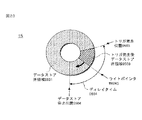
FIG. 21 is a diagram showing an internal state of the
すなわち、時刻t4から図21に示すようにメモリアクセス制御部0304は、データストア済領域0501の先頭アドレスから新たにストアすべきデータを上書きしていく。それに従ってリングバッファにより構成されたバッファメモリ部0109内部のストアデータ先頭アドレスADRS3はライトポインタWADRSに追従して、トリガ発生待ちによるデータ上書き済領域0507が発生する。
That is, from time t4, as shown in FIG. 21, the memory
図22は、図13乃至図17に示す本発明の実施の形態2の光ディスク装置で、時刻tAにおけるリングバッファにより構成されたバッファメモリ部0109の内部状態を示す図である。
FIG. 22 is a diagram showing an internal state of the
すなわち、図22に示すようにトリガが発生した時刻tAにおいて、メモリアクセス制御部0304は、トリガ発生時のライトポインタWADRSのアドレスを、トリガ発生位置0503とする。
That is, as shown in FIG. 22, at time tA when the trigger is generated, the memory
図23は、図13乃至図17に示す本発明の実施の形態2の光ディスク装置で、時刻t5におけるリングバッファにより構成されたバッファメモリ部0109の内部状態を示す図である。
FIG. 23 is a diagram showing an internal state of the
すなわち、図23に示すように、トリガ発生後ではメモリアクセス制御部0304は設定ディレイタイム0604の期間中にリングバッファにより構成されたバッファメモリ部0109へのデータのストアを継続するので、トリガ発生後データストア済領域0508が発生する。
That is, as shown in FIG. 23, after the trigger occurs, the memory
図24は、図13乃至図17に示す本発明の実施の形態2の光ディスク装置で、時刻tBにおけるリングバッファにより構成されたバッファメモリ部0109の内部状態を示す図である。
FIG. 24 is a diagram showing an internal state of the
すなわち、図24に示すように、メモリアクセス制御部0304は、リングバッファによって構成されたバッファメモリ部0109へディレイタイム0604による指定期間分のデータストアの完了時点でデータストアをデータストア停止位置0504で停止する。データストア停止後、リングバッファ制御部0305は、メモリアクセス制御部0304からの制御に基づいて出力すべきデータ領域の先頭データのアドレスにリードポインタRADRSを設定する。ここで、ディレイタイム0604による指定期間分のデータストアが実施したか否かの判定方法としては、例えば、図22に示したトリガが発生した時刻tAの以降のデータストアを実行する際に、データのストアに伴って設定ディレイタイム0604の値を1つデクリメントして、ディレイタイム0604の値がゼロになるタイミングをディレイタイム0604による指定期間分のデータストア終了のタイミングと判定することが可能となる。
That is, as shown in FIG. 24, the memory
図25は、図13乃至図17に示す本発明の実施の形態2の光ディスク装置で、時刻t6におけるリングバッファにより構成されたバッファメモリ部0109の内部状態を示す図である。
FIG. 25 is a diagram showing an internal state of the
システム制御部0111からメモリアクセス制御部0304へデータロード開始命令が供給されると、メモリアクセス制御部0304は図25に示すデータロード開始位置0505であるリードポインタRADRSからリングバッファにより構成されたバッファメモリ部0109にストアされているデータのロードを開始する。
When a data load start command is supplied from the
図26は、図13乃至図17に示す本発明の実施の形態2の光ディスク装置で、時刻t7におけるリングバッファにより構成されたバッファメモリ部0109の内部状態を示す図である。
FIG. 26 is a diagram showing an internal state of the
すなわち、図26に示すように、メモリアクセス制御部0304は、時刻t7でリングバッファによって構成されたバッファメモリ部0109にストアされている全データのロードを完了する。
That is, as shown in FIG. 26, the memory
《リードポインタとライトポインタ》
図27は、図13乃至図26に示す本発明の実施の形態2の光ディスク装置において、リングバッファにより構成されたバッファメモリ部0109内部のリードポインタRADRSとライトポインタWADRSの値の変化を示す図である。
《Read pointer and write pointer》
FIG. 27 is a diagram illustrating changes in values of the read pointer RADRS and the write pointer WADRS in the
図27において、波形(A)はリングバッファによって構成されたバッファメモリ部0109内部のライトポインタWADRSの値の変化を示し、波形(B)はリングバッファによって構成されたバッファメモリ部0109内部のリードポインタRADRSの値の変化を示す。
In FIG. 27, a waveform (A) shows a change in the value of the write pointer WADRS in the
図27の波形(A)は、ライトポインタWADRSの初期値として開始アドレスADRS1を指定した場合の例を示している。時刻t1において、リングバッファによって構成されたバッファメモリ部0109へのデータストアが開始されると、データストアに従ってリングバッファ制御部0305はライトポインタWADRSの値をインクリメントする。時刻t2を経由して時刻t3で、ライトポインタWADRSが終了アドレスADRS2に到達すると、ライトポインタWADRSの値は開始アドレスADRS1の値に戻される。トリガ未発生の間では、時刻t1から時刻t3までの動作が繰り返されこととなる。
The waveform (A) in FIG. 27 shows an example when the start address ADRS1 is designated as the initial value of the write pointer WADRS. When the data store to the
時刻tAにおいてトリガが発生すると、その後、メモリアクセス制御部0304は、設定ディレイタイム0604の期間にデータストアを継続する。時刻tBにおいてディレイタイム0604の期間分のデータのストアの終了時点で、メモリアクセス制御部0304はライトポインタWADRSの値のインクリメントを停止する。
When a trigger occurs at time tA, the memory
図27の波形(B)では、時刻tBの以前で、リードポインタRADRSの値が未確定の状態である。時刻tBでは、リングバッファ制御部0305はリードポインタRADRSの値を図25に示すアドレスに設定する。時刻t6にて、システム制御部0111がメモリアクセス制御部0304にデータロード開始命令を供給すると、バッファメモリ部0109から外部I/F部0110へのデータロードが開始されて、データロードに伴いリードポインタRADRSの値はインクリメントされる。リードアドレスが終了アドレスADRS2に到達した場合には、上述のライトアドレスの場合と同様に開始アドレスADRS1の値に戻される。その後、時刻t7にて、リングバッファにより構成されたバッファメモリ部0109内部の全データが出力され、データ出力が終了するとリードポインタの値の変化は停止する。
In the waveform (B) of FIG. 27, the value of the read pointer RADRS is indeterminate before time tB. At time tB, the ring
上述のリングバッファにより構成されたバッファメモリ部0109を使用した処理済みサーボモニタ信号A102のストア動作では、トリガ発生待ちの期間にリングバッファ内部の古いデータの新しいデータによる上書きを継続することにより、トリガが発生した時点でリングバッファ内部にトリガ発生以前のデータをストアすることが可能となる。またディレイタイム0604を設定することにより、トリガ発生後のデータストア期間の調整が可能となる。これにより、トリガ発生前後の現象データをバッファメモリ部0109へストアする際に、観測条件とトリガ発生前後のデータ量の比とを設定した状態でバッファメモリ部0109にデータをストアすることができる。更に光ディスク装置0001から外部PC0002へのデータ転送量は1回のトリガ動作につきリングバッファ1周分であるため、外部PC0002内部のデータ受信バッファメモリの記憶容量を低減可能となる。データ転送量については、リングバッファの1周分のデータを1回転送すればよいので、リングバッファ内部のデータの常時転送の場合に比較して、外部I/F部0110の転送負荷が低減可能となり、データ転送の消費電力も低減可能となる。またトリガ発生後にリングバッファ1周分のデータを転送する場合以外では、外部PC0002へのデータ常時転送が不必要となるので、外部I/F部0110の転送負荷が低減可能となる。
In the store operation of the processed servo monitor signal A102 using the
《トリガ発生》
図28は、図13乃至図27に示す本発明の実施の形態2の光ディスク装置において、バッファメモリ部0109へのデータストアのトリガ発生を示す図である。
<Trigger generation>
FIG. 28 is a diagram showing generation of a data store trigger to the
メモリアクセス制御部0304はトリガ発生時にトリガ制御部0306から生成されるトリガ発生の通知に基づいて、時刻tAでのトリガ発生位置0503から時刻tBまでのディレイタイム0604が示す期間dt分のデータをバッファメモリ部0109へストアし続け、時刻tBのデータストア停止位置0504においてデータストア動作を停止する。その後、システム制御部0111からのデータロード開始命令に応答して、メモリアクセス制御部0304は外部I/F部0110を介して光ディスク装置0001外部のPC0002へデータを転送する。しかし、転送されたデータをPC0002で処理する場合には、転送されたデータ内部の波形データA001aだけではトリガ発生位置0503を判断することが不可能である。
The memory
そこで、図28に示す本発明の実施の形態2の光ディスク装置において、バッファ制御状態信号A104の1ビットに、トリガ発生を示すフラグビット(以下、トリガ発生フラグと称する)を配置する。このトリガ発生フラグは、初期値を“0”とし、トリガが未発生の間は“0”のままで変化しない。トリガが発生したタイミングで、トリガ発生フラグは“0”から“1”へ値が変化して、ディレイタイム0604で指定した期間の間では“1”の値が継続される。ディレイタイム0604の指定期間dtのデータストアが終了して、リングバッファ内部の全データが外部のPC0002へ転送された後に、トリガ発生フラグを“1”から“0”にクリアすることが可能であり、他の方法ではデータストア処理の再開開始前にトリガ発生フラグを“1”から“0”にクリアすることも可能である。
Therefore, in the optical disc apparatus according to the second embodiment of the present invention shown in FIG. 28, a flag bit indicating trigger generation (hereinafter referred to as trigger generation flag) is arranged in one bit of the buffer control state signal A104. The trigger generation flag has an initial value of “0” and remains “0” while the trigger is not generated. At the timing when the trigger occurs, the value of the trigger generation flag changes from “0” to “1”, and the value of “1” is continued during the period specified by the
このようにバッファ制御状態信号A104にトリガ発生フラグを設定して、図28に示すようにバッファメモリ部0109にデータとともにストアされたトリガ発生フラグを参照することにより、バッファメモリ部0109内部の全ストアデータからトリガ発生タイミングのストアデータを容易に観測可能となる。
Thus, by setting the trigger generation flag in the buffer control state signal A104 and referring to the trigger generation flag stored together with the data in the
図28に示す本発明の実施の形態2の光ディスク装置によれば、光ディスク装置を分解せずサーボ制御部内部の信号を観測する際に、トリガ機能を付加して、トリガ判定条件を設定することにより、目的の現象が発生する前後の時刻のサーボ制御部内部の信号を、光ディスク装置が自動的に内部メモリへストアすることが可能となる。光ディスク装置が自動的に内部メモリへストアしたデータを、外部のPCへ転送することが可能となるため、光ディスク装置の現象解析を容易に実行可能となる。 According to the optical disk device of the second embodiment of the present invention shown in FIG. 28, when observing a signal inside the servo control unit without disassembling the optical disk device, a trigger function is added and a trigger determination condition is set. Thus, the optical disk device can automatically store the signal in the servo control unit at the time before and after the occurrence of the target phenomenon in the internal memory. Since the data automatically stored in the internal memory by the optical disk device can be transferred to an external PC, the phenomenon analysis of the optical disk device can be easily performed.
本発明の実施の形態2のようにトリガ機能を具備しない光ディスク装置において目的の現象の観測を実行する場合には、目的の現象の発生前から発生以降までの全データを外部のPCに転送して、更に転送された全データをPC内部に格納して、格納された全データからの目的の現象の検索が必要となる。この場合には、PC内部に大容量のメモリやストレージが必要となり、また膨大なデータから目的の現象を検索する処理が必要となる。それに対して、図28に示す本発明の実施の形態2の光ディスク装置では、PC内部に必要なメモリ容量はリングバッファ1周分で十分で、更に目的の現象が発生した前後の時刻におけるサーボ制御部内部の信号はすでにリングバッファ1周分のメモリ内部にトリガ発生フラグ情報が付加された状態でストアされているので、膨大なデータから目的の現象を検索する処理も不要となる。その結果、光ディスク装置の現象解析を実行する際に、PC内部に大容量メモリを増設する必要がなく、更に容易に現象解析を実行することが可能となる。 When observing a target phenomenon in an optical disc apparatus that does not have a trigger function as in the second embodiment of the present invention, all data from before the occurrence of the target phenomenon to after it occurs is transferred to an external PC. Further, it is necessary to store all the transferred data in the PC and search for the target phenomenon from all the stored data. In this case, a large-capacity memory or storage is required inside the PC, and processing for searching for a target phenomenon from a huge amount of data is required. On the other hand, in the optical disk apparatus according to the second embodiment of the present invention shown in FIG. 28, the memory capacity required in the PC is sufficient for one round of the ring buffer, and servo control at the time before and after the target phenomenon occurs. Since the internal signal is already stored in the memory for one round of the ring buffer with the trigger generation flag information added, processing for searching for the target phenomenon from a huge amount of data is also unnecessary. As a result, when performing the phenomenon analysis of the optical disk apparatus, it is not necessary to add a large capacity memory inside the PC, and the phenomenon analysis can be performed more easily.
また、図28に示す本発明の実施の形態2の光ディスク装置では、光ディスク装置からPCへ転送するデータ量は、目的の現象の観測を1回実行するために、リングバッファ1周分で十分あり、PCへのデータ転送回数も1回で十分ある。従って、光ディスク装置と外部のPCの間でのデータ常時転送が不必要となるので、外部I/F部0110の転送負荷が低減可能となるとともに、データ転送のための消費電力量を低減することが可能となる。
In the optical disk apparatus according to the second embodiment of the present invention shown in FIG. 28, the amount of data transferred from the optical disk apparatus to the PC is sufficient for one round of the ring buffer in order to execute the observation of the target phenomenon once. A single data transfer to the PC is sufficient. Accordingly, since the constant data transfer between the optical disc apparatus and the external PC is not necessary, the transfer load of the external I /
[実施の形態3]
《光ディスクドライブ記録再生装置の構成》
図29は、本発明の実施の形態3による光ディスクドライブ記録再生装置の構成を示す図である。
[Embodiment 3]
<< Configuration of optical disk drive recording / playback apparatus >>
FIG. 29 is a diagram showing a configuration of an optical disc drive recording / reproducing apparatus according to
図29の本発明の実施の形態3による光ディスクドライブ記録再生装置が図1乃至図12に示した本発明の実施の形態1による光ディスク装置と相違するのは、図29のAFE/ADC部0105は、AFE/ADC部0105内部で生成してデジタル化したRF信号を光ディスク装置0001外部で観測できるようにRFモニタ信号A005としてバッファ制御部0108へ出力する機能を有することである。
The optical disk drive recording / reproducing apparatus according to the third embodiment of the present invention shown in FIG. 29 is different from the optical disk apparatus according to the first embodiment of the present invention shown in FIGS. 1 to 12 in that the AFE /
図29の本発明の実施の形態3の光ディスク装置0001によれば、サーボモニタ信号A001の他に、RFモニタ信号A005もバッファメモリ部0109にストアすることが可能となる。またバッファメモリ部0109にストアされたリードデータA002を光ディスク装置0001外部のPC0002へ転送するハードウェアと同様のハードウェアを使用して、RFモニタ信号A005を光ディスク装置0001外部のPC0002へ転送することが可能となる。
According to the
図30は、図29に示す本発明の実施の形態3による光ディスク装置に含まれるサーボ制御部0106とバッファ制御部0108の詳細な内部構成を示す図である。
FIG. 30 is a diagram showing a detailed internal configuration of the
図30の本発明の実施の形態3による光ディスクドライブ記録再生装置が図1乃至図12に示した本発明の実施の形態1による光ディスク装置と相違するのは、図30のバッファ制御部0108にRFモニタ信号処理部0307が追加されていることである。このRFモニタ信号処理部0307の入力端子には図29のAFE/ADC部0105から生成されるRFモニタ信号A005が供給され、RFモニタ信号処理部0307の出力端子の処理済RFモニタ信号A103はメモリアクセス制御部0304に供給される。
The optical disk drive recording / reproducing apparatus according to the third embodiment of the present invention shown in FIG. 30 is different from the optical disk apparatus according to the first embodiment of the present invention shown in FIGS. 1 to 12 in that the
バッファ制御部0108のサンプリング制御部0303は、システム制御部0111の制御に基づいて、システムクロック生成部0114が出力するシステムクロック信号A004bの逓倍処理や分周処理を実行することによって周波数f6のサンプリングクロック信号Clk6を生成して、RFモニタ信号処理部0307へ供給する。
The
RFモニタ信号処理部0307はサンプリング制御部0303から供給されるサンプリングクロック信号Clk6に同期してRFモニタ信号A005を取り込み、バッファリングを実行する。またシステム制御部0111とメモリアクセス制御部0304の制御に基づいて、RFモニタ信号処理部0307はRFモニタ信号A005をバッファリングすることによってバーストデータを生成して処理済RFモニタ信号A103として出力する。
The RF monitor
図29と図30に示す本発明の実施の形態3による光ディスク装置0001では、メモリアクセス制御部0304が供給された処理済みリードデータA101と処理済みサーボモニタ信号A102と処理済RFモニタ信号A103とを取り込んでバッファメモリ部0109へストアする際にストアするデータを選択可能であることと、リードデータ処理部0301とサーボモニタ信号処理部0302とRFモニタ信号処理部0307のデータ入力のデータ転送レートと比較してメモリアクセス制御部0304へのデータ出力のデータ転送レートを高く設定することによってメモリアクセス制御部0304は処理済みリードデータA101と処理済みサーボモニタ信号A102と処理済RFモニタ信号A103のデータを時分割でバッファメモリ部0109にストアすることができる。
In the
図29と図30に示す本発明の実施の形態3によれば、光ディスク装置を分解せずにサーボ制御部内部の信号とRF信号とを観測する際に、サーボ制御部内部の信号とRF信号とを光ディスク装置内部のバッファメモリへストア可能なことと、光ディスク装置によって光ディスクから読み出されたデータとサーボ制御部内部の信号とRF信号とを、光ディスク装置内部のバッファメモリへストア可能なことにより、光ディスクから読み出されたデータとサーボ制御部内部の信号とRF信号を光ディスク装置外部のPCへ出力して観測可能となり、動作中の光ディスク装置の特性解析を容易に実行することが可能となる。 According to the third embodiment of the present invention shown in FIG. 29 and FIG. 30, when observing the signal and the RF signal inside the servo control unit without disassembling the optical disk apparatus, the signal and the RF signal inside the servo control unit are observed. Can be stored in the buffer memory inside the optical disk device, and the data read from the optical disk by the optical disk device, the signal inside the servo control unit and the RF signal can be stored in the buffer memory inside the optical disk device. The data read from the optical disc, the signal inside the servo control unit and the RF signal can be output to the PC outside the optical disc apparatus for observation, and the characteristic analysis of the operating optical disc apparatus can be easily executed. .
サーボ系信号の処理済みサーボモニタ信号A102とリード系信号の処理済RFモニタ信号A103とを略同時に観測可能であるので、再生品質に問題があった場合にサーボ系とリード系のいずれに不具合の原因があるのかの解析を容易に実行することが可能となる。またサーボ制御部内部の信号とRF信号とを光ディスク装置内部のバッファメモリへデジタルデータとしてストアして、光ディスク装置外部のPCへ出力することが可能となるため、PC内部に取り込まれたサーボ制御部内部の信号とRF信号とのデジタルデータを解析する際に、PCで波形描写アプリケーション等を使用することによってサーボ制御部内部の信号やRF信号の波形を時間的な関係も含め再現することが可能となる。その結果、オシロスコープ、ロジックアナライザ、データレコーダ等の外部測定器を使用することなく、光ディスク装置と外部PCとで、サーボ制御部内部の信号とRF信号との波形観測が可能となる。 The servo system signal processed servo monitor signal A102 and the read system signal processed RF monitor signal A103 can be observed almost simultaneously, so if there is a problem in reproduction quality, there is a problem with either the servo system or the read system. It is possible to easily analyze whether there is a cause. Further, since the signal inside the servo control unit and the RF signal can be stored as digital data in a buffer memory inside the optical disc apparatus and output to a PC outside the optical disc apparatus, the servo control unit incorporated in the PC When analyzing the digital data of the internal signal and RF signal, it is possible to reproduce the internal signal of the servo control unit and the waveform of the RF signal, including the time relationship, by using the waveform drawing application on the PC. It becomes. As a result, it is possible to observe the waveform of the signal inside the servo control unit and the RF signal by using the optical disc apparatus and the external PC without using an external measuring instrument such as an oscilloscope, a logic analyzer, or a data recorder.
また、図29と図30に示す本発明の実施の形態3による光ディスク装置0001では、外部のPC0002へ光ディスク0101からのリードデータA002を出力する処理に追加して、サーボモニタ信号A001とRFモニタ信号A005を出力可能とされたものである。別の実施の形態としては、光ディスク0101からのリードデータA002に追加して、RFモニタ信号A005のみを出力することも可能である。
In addition, in the
また、図29と図30に示す本発明の実施の形態3による光ディスク装置0001に、上述した本発明の第2の実施の形態による光ディスク装置0001のリングバッファにより構成されたバッファメモリ部0109とトリガ判定機能とを付加することも可能である。また処理済RFモニタ信号A103を、トリガ判定の対象とすることも可能である。
In addition, the
以上本発明者によってなされた発明を種々の実施の形態に基づいて具体的に説明したが、本発明はそれに限定されるものではなく、その要旨を逸脱しない範囲において種々変更可能であることは言うまでもない。 Although the invention made by the present inventor has been specifically described based on various embodiments, it is needless to say that the present invention is not limited thereto and can be variously modified without departing from the scope of the invention. Yes.
例えば、半導体集積回路LSIの半導体チップの製造プロセスがオンチップ・ダイナミックランダムアクセスメモリ(DRAM)の形成プロセスを含むことによって、バッファメモリ部0109を構成する同期ダイナミックランダムアクセスメモリは半導体集積回路LSIの半導体チップに内蔵可能とされる。
For example, the semiconductor chip manufacturing process of the semiconductor integrated circuit LSI includes an on-chip dynamic random access memory (DRAM) forming process, so that the synchronous dynamic random access memory constituting the
また更に本発明はCD、DVD、BD等の着脱可能なリムーバブル型の光ディスクを使用する光ディスクドライブ記録再生装置に限定されるものではなく、ディスクドライブ記録再生装置に固定されたハードディスクを使用するHDD記録再生装置に適用することも可能である。 Further, the present invention is not limited to an optical disk drive recording / reproducing apparatus using a removable removable optical disk such as a CD, DVD, BD, etc., and HDD recording using a hard disk fixed to the disk drive recording / reproducing apparatus. It can also be applied to a playback device.
0001…光ディスク装置
0002…PC
0101…光ディスク
0102…スピンドルモータ部
0103…スレッドモータ部
0104…ピックアップ部
0105…AFE/ADC部
0106…サーボ制御部
0107…リード/ライト制御部
0108…バッファ制御部
0109…バッファメモリ部
0110…外部I/F部
0111…システム制御部
0112…操作部
0113…表示部
0114…システムクロック生成部
0201…波形データ出力部
0202…ロジック信号出力部
0203…ステータス情報出力部
0204…サーボクロック生成部
0301…リードデータ処理部
0302…サーボモニタ信号処理部
0303…サンプリング制御部
0304…メモリアクセス制御部
0305…リングバッファ制御部
0306…トリガ制御部
0307…RFモニタ信号処理部
0401…波形データビット精度変換部
0402…出力データ選択部
0403…出力データ生成部
0501…データストア済領域
0502…データ未ストア領域
0503…トリガ発生位置
0504…データストア停止位置
0505…データロード開始位置
0507…トリガ発生待ちによるデータ上書き済み領域
0508…トリガ発生後データストア済領域
0601…トリガ判定対象信号
0602…トリガエッジ
0603…トリガレベル
0604…ディレイタイム
A001…サーボモニタ信号
A001a…波形データ
A001b…ロジック信号
A001c…ステータス情報
A002…リードデータ
A003…ライトデータ
A004…システムクロック信号
A005…RFモニタ信号
A101…処理済リードデータ
A102…処理済サーボモニタ信号
A103…処理済RFモニタ信号
A104…バッファ制御状態信号
B001…メモリバス
B002…入出力データバス
S101…バッファメモリ設定
S102…モニタ信号設定
S103…サンプリング設定
S201…トリガ設定
ADRS1…開始アドレス
ADRS2…終了アドレス
ADRS3…ストアデータ先頭アドレス
RADRS…リードポインタ
WADRS…ライトポインタ
0001 ...
DESCRIPTION OF
Claims (47)
前記半導体集積回路は、前記データ読み出しによって前記ピックアップから読み出されるRF信号の信号処理によって前記読み出しデータを生成可能な信号処理部と、前記ピックアップから読み出されるサーボ誤差信号に応答して前記スピンドルモータと前記ピックアップと前記ピックアップ駆動モータとを制御可能なサーボ制御部とを含み、
前記半導体集積回路は、前記信号処理部から生成される前記読み出しデータと前記サーボ制御部から生成されるサーボ信号とが供給され前記バッファメモリと接続可能とされたメモリ制御部と、前記半導体集積回路の外部装置と接続可能とされて前記メモリ制御部と接続された外部インターフェースとを更に含み、
前記メモリ制御部は前記読み出しデータと前記サーボ信号とを時分割処理によって前記バッファメモリに格納可能とされ、前記バッファメモリに前記時分割処理によって格納された前記読み出しデータと前記サーボ信号とは前記メモリ制御部によって前記外部インターフェースを介して前記外部装置に転送可能とされたことを特徴とする半導体集積回路。 A spindle motor capable of rotating the disk, a pickup capable of executing data writing to the disk and data reading from the disk, a pickup driving motor capable of driving the pickup, data read from the disk and the disk A semiconductor integrated circuit that can be mounted on a disk drive recording / reproducing apparatus having a buffer memory capable of storing the write data of
The semiconductor integrated circuit includes a signal processing unit capable of generating the read data by signal processing of an RF signal read from the pickup by the data reading, the spindle motor and the spindle in response to a servo error signal read from the pickup A servo control unit capable of controlling the pickup and the pickup drive motor,
The semiconductor integrated circuit is supplied with the read data generated from the signal processing unit and a servo signal generated from the servo control unit, and is connected to the buffer memory, and the semiconductor integrated circuit An external interface that is connectable to the external controller and connected to the memory control unit,
The memory control unit can store the read data and the servo signal in the buffer memory by time division processing, and the read data and the servo signal stored in the buffer memory by the time division processing are stored in the memory. A semiconductor integrated circuit characterized in that it can be transferred to the external device via the external interface by a control unit.
前記振幅レベルが前記所定値を超過したことに応答して前記メモリ制御部は前記サーボ信号の前記リングバッファへの格納を開始して、所定時間の経過後に前記メモリ制御部は前記サーボ信号の前記リングバッファへの格納を停止することを特徴とする請求項4に記載の半導体集積回路。 The memory control unit detects that an amplitude level of the servo signal stored in the ring buffer exceeds a predetermined value;
In response to the amplitude level exceeding the predetermined value, the memory control unit starts storing the servo signal in the ring buffer, and after a predetermined time elapses, the memory control unit 5. The semiconductor integrated circuit according to claim 4, wherein storage in the ring buffer is stopped.
前記半導体集積回路は、前記データ読み出しによって前記ピックアップから読み出されるRF信号の信号処理によって前記読み出しデータを生成可能な信号処理部と、前記ピックアップから読み出されるサーボ誤差信号に応答して前記スピンドルモータと前記ピックアップと前記ピックアップ駆動モータとを制御可能なサーボ制御部とを含み、
前記半導体集積回路は、前記信号処理部から生成される前記読み出しデータと前記サーボ制御部から生成されるサーボ信号とが供給され前記バッファメモリと接続可能とされたメモリ制御部と、前記半導体集積回路の外部装置と接続可能とされて前記メモリ制御部と接続された外部インターフェースとを更に含み、
前記メモリ制御部は前記読み出しデータと前記サーボ信号とを時分割処理によって前記バッファメモリに格納可能とされ、前記バッファメモリに前記時分割処理によって格納された前記読み出しデータと前記サーボ信号とは前記メモリ制御部によって前記外部インターフェースを介して前記外部装置に転送可能とされたことを特徴とするディスクドライブ記録再生装置。 A spindle motor capable of rotating the disk, a pickup capable of executing data writing to the disk and data reading from the disk, a pickup driving motor capable of driving the pickup, data read from the disk and the disk A disk drive recording / reproducing apparatus comprising a buffer memory capable of storing the write data and a semiconductor integrated circuit,
The semiconductor integrated circuit includes a signal processing unit capable of generating the read data by signal processing of an RF signal read from the pickup by the data reading, the spindle motor and the spindle in response to a servo error signal read from the pickup A servo control unit capable of controlling the pickup and the pickup drive motor,
The semiconductor integrated circuit is supplied with the read data generated from the signal processing unit and a servo signal generated from the servo control unit, and is connected to the buffer memory, and the semiconductor integrated circuit An external interface that is connectable to the external controller and connected to the memory control unit,
The memory control unit can store the read data and the servo signal in the buffer memory by time division processing, and the read data and the servo signal stored in the buffer memory by the time division processing are stored in the memory. A disk drive recording / reproducing apparatus characterized in that it can be transferred to the external apparatus via the external interface by a control unit.
前記振幅レベルが前記所定値を超過したことに応答して前記メモリ制御部は前記サーボ信号の前記リングバッファへの格納を開始して、所定時間の経過後に前記メモリ制御部は前記サーボ信号の前記リングバッファへの格納を停止することを特徴とする請求項14に記載のディスクドライブ記録再生装置。 The memory control unit detects that an amplitude level of the servo signal stored in the ring buffer exceeds a predetermined value;
In response to the amplitude level exceeding the predetermined value, the memory control unit starts storing the servo signal in the ring buffer, and after a predetermined time elapses, the memory control unit 15. The disk drive recording / reproducing apparatus according to claim 14, wherein storage in the ring buffer is stopped.
該読み取り手段を制御するサーボ制御手段と、
該サーボ制御手段より出力されるサーボ制御信号と前記読み取り手段により読み取られた再生信号の少なくとも1つを記録する記録手段と、
該記録手段を制御する記録制御手段と、
該記録手段に記録された前記サーボ制御信号と前記再生信号の少なくとも1つを出力する出力手段と、
前記サーボ制御手段と前記記録制御手段と該出力手段を制御するシステム制御手段と、
を備えることを特徴とする光ディスク装置。 Reading means for reading a reproduction signal from the information recording medium;
Servo control means for controlling the reading means;
Recording means for recording at least one of a servo control signal output from the servo control means and a reproduction signal read by the reading means;
Recording control means for controlling the recording means;
Output means for outputting at least one of the servo control signal and the reproduction signal recorded in the recording means;
System control means for controlling the servo control means, the recording control means, and the output means;
An optical disc apparatus comprising:
該読み取りステップを制御するサーボ制御ステップと、
該サーボ制御ステップより出力されるサーボ制御信号と前記読み取りステップにより読み取られた再生信号の少なくとも1つを記録する記録ステップと、
該記録ステップを制御する記録制御ステップと、
該記録ステップに記録された前記サーボ制御信号と前記再生信号の少なくとも1つを出力する出力ステップと、
前記サーボ制御ステップと前記記録制御ステップと該出力ステップを制御するシステム制御ステップと、
を備えることを特徴とする光ディスク記録または再生方式。 A reading step of reading a reproduction signal from the information recording medium;
A servo control step for controlling the reading step;
A recording step for recording at least one of a servo control signal output from the servo control step and a reproduction signal read by the reading step;
A recording control step for controlling the recording step;
An output step for outputting at least one of the servo control signal and the reproduction signal recorded in the recording step;
A system control step for controlling the servo control step, the recording control step, and the output step;
An optical disc recording or reproducing system comprising:
前記ピックアップ手段が出力する該電気信号に基づき、サーボ誤差信号とRF信号を出力するアナログ信号処理手段と、
該アナログ信号処理手段が出力する該RF信号に基づき、再生信号を生成するリード手段と、
前記アナログ信号処理手段から出力される前記サーボ誤差信号を用いてサーボ制御信号を演算し、該サーボ制御信号を用いて前記ピックアップ手段を制御し、サーボ誤差演算信号とサーボ演算制御信号とサーボ動作状態信号のいずれかまたは組み合わせの信号を出力するサーボ制御手段と、
該サーボ誤差演算信号と該サーボ演算制御信号と該サーボ動作状態信号のいずれかまたは組み合わせの信号と前記再生信号を記録するバッファメモリ手段と、
該バッファメモリ手段の記録処理や読出し処理を制御するバッファ制御手段と、
前記リード手段と前記サーボ制御手段と該バッファ制御手段を制御するシステム制御手段と、
前記バッファ制御手段や該システム制御手段に対して、前記サーボ誤差演算信号と前記サーボ演算制御信号と前記サーボ動作状態信号のいずれかまたは組み合わせの信号と前記再生信号と制御データの受け渡しを行い、装置外と通信を行う外部インターフェース手段と、
を備え、
前記バッファメモリ手段に記録した前記サーボ誤差演算信号と前記サーボ演算制御信号と前記サーボ動作状態信号のいずれかまたは組み合わせの信号と前記再生信号を装置外へ出力すること、
を特徴とする光ディスク装置。 Pickup means for outputting an electrical signal based on reflected light from the laser light irradiated on the information recording medium;
An analog signal processing means for outputting a servo error signal and an RF signal based on the electrical signal output by the pickup means;
Read means for generating a reproduction signal based on the RF signal output from the analog signal processing means;
A servo control signal is calculated using the servo error signal output from the analog signal processing means, the pickup means is controlled using the servo control signal, a servo error calculation signal, a servo calculation control signal, and a servo operation state. Servo control means for outputting one or a combination of signals;
Buffer memory means for recording a signal of any one or a combination of the servo error calculation signal, the servo calculation control signal, and the servo operation state signal, and the reproduction signal;
Buffer control means for controlling recording processing and reading processing of the buffer memory means;
System control means for controlling the read means, the servo control means, and the buffer control means;
The buffer control means and the system control means are exchanged with any one or combination of the servo error calculation signal, the servo calculation control signal, and the servo operation state signal, the reproduction signal, and control data, and an apparatus An external interface means for communicating with the outside;
With
Outputting the servo error calculation signal recorded in the buffer memory means, the servo calculation control signal, the servo operation state signal, a combination signal, and the reproduction signal to the outside of the device;
An optical disc apparatus characterized by the above.
前記ピックアップステップが出力する該電気信号に基づき、サーボ誤差信号とRF信号を出力するアナログ信号処理ステップと、
該アナログ信号処理ステップが出力する該RF信号に基づき、再生信号を生成するリードステップと、
前記アナログ信号処理ステップから出力される前記サーボ誤差信号を用いてサーボ制御信号を演算し、該サーボ制御信号を用いて前記ピックアップステップを制御し、サーボ誤差演算信号とサーボ演算制御信号とサーボ動作状態信号のいずれかまたは組み合わせの信号を出力するサーボ制御ステップと、
該サーボ誤差演算信号と該サーボ演算制御信号と該サーボ動作状態信号のいずれかまたは組み合わせの信号と前記再生信号を記録するバッファメモリステップと、
該バッファメモリステップの記録処理や読出し処理を制御するバッファ制御ステップと、
前記リードステップと前記サーボ制御ステップと該バッファ制御ステップを制御するシステム制御ステップと、
前記バッファ制御ステップや該システム制御ステップに対して、前記サーボ誤差演算信号と前記サーボ演算制御信号と前記サーボ動作状態信号のいずれかまたは組み合わせの信号と前記再生信号と制御データの受け渡しを行い、装置外と通信を行う外部インターフェースステップと、
を備え、
前記バッファメモリステップに記録した前記サーボ誤差演算信号と前記サーボ演算制御信号と前記サーボ動作状態信号のいずれかまたは組み合わせの信号と前記再生信号を装置外へ出力すること、
を特徴とする光ディスク記録または再生方式。 A pickup step for outputting an electrical signal based on the reflected light from the laser light applied to the information recording medium;
An analog signal processing step for outputting a servo error signal and an RF signal based on the electrical signal output by the pickup step;
A read step for generating a reproduction signal based on the RF signal output by the analog signal processing step;
A servo control signal is calculated using the servo error signal output from the analog signal processing step, the pickup step is controlled using the servo control signal, a servo error calculation signal, a servo calculation control signal, and a servo operation state. A servo control step for outputting one or a combination of signals;
A buffer memory step for recording a signal of any one or a combination of the servo error calculation signal, the servo calculation control signal, and the servo operation state signal, and the reproduction signal;
A buffer control step for controlling the recording process and the reading process of the buffer memory step;
A system control step for controlling the read step, the servo control step, and the buffer control step;
For the buffer control step and the system control step, the servo error calculation signal, the servo calculation control signal, the servo operation state signal, or a combination signal, the reproduction signal, and control data are exchanged. An external interface step to communicate with the outside,
With
Outputting the servo error calculation signal recorded in the buffer memory step, the servo calculation control signal, the servo operation state signal, or a combination signal and the reproduction signal to the outside of the device;
An optical disc recording or reproducing system characterized by
前記ピックアップ手段が出力する該電気信号に基づき、サーボ誤差信号とRF信号を出力するアナログ信号処理手段と、
該アナログ信号処理手段が出力する該RF信号に基づき、再生信号を生成するリード手段と、
前記アナログ信号処理手段から出力される前記サーボ誤差信号を用いてサーボ制御信号を演算し、該サーボ制御信号を用いて前記ピックアップ手段を制御し、サーボ誤差演算信号とサーボ演算制御信号とサーボ動作状態信号のいずれかまたは組み合わせの信号を出力するサーボ制御手段と、
該サーボ誤差演算信号と該サーボ演算制御信号と該サーボ動作状態信号のいずれかまたは組み合わせの信号と前記再生信号を記録するバッファメモリ手段と、
前記サーボ誤差演算信号と前記サーボ演算制御信号と前記サーボ動作状態信号のいずれかまたは組み合わせの信号に対してトリガ判定処理を行い、トリガ発生判定に基づいて前記バッファメモリ手段の記録処理や読出し処理を制御するバッファ制御手段と、
前記リード手段と前記サーボ制御手段と該バッファ制御手段を制御するシステム制御手段と、
前記バッファ制御手段や該システム制御手段に対して、前記サーボ誤差演算信号と前記サーボ演算制御信号と前記サーボ動作状態信号のいずれかまたは組み合わせの信号と前記再生信号と制御データの受け渡しを行い、装置外と通信を行う外部インターフェース手段と、
を備え、
前記バッファメモリ手段に記録した前記サーボ誤差演算信号と前記サーボ演算制御信号と前記サーボ動作状態信号のいずれかまたは組み合わせの信号と前記再生信号を装置外へ出力すること、
を特徴とする光ディスク装置。 Pickup means for outputting an electrical signal based on reflected light from the laser light irradiated on the information recording medium;
An analog signal processing means for outputting a servo error signal and an RF signal based on the electrical signal output by the pickup means;
Read means for generating a reproduction signal based on the RF signal output from the analog signal processing means;
A servo control signal is calculated using the servo error signal output from the analog signal processing means, the pickup means is controlled using the servo control signal, a servo error calculation signal, a servo calculation control signal, and a servo operation state. Servo control means for outputting one or a combination of signals;
Buffer memory means for recording a signal of any one or a combination of the servo error calculation signal, the servo calculation control signal, and the servo operation state signal, and the reproduction signal;
Trigger determination processing is performed on any one or combination of the servo error calculation signal, the servo calculation control signal, and the servo operation state signal, and recording processing and reading processing of the buffer memory unit are performed based on the trigger generation determination. Buffer control means to control;
System control means for controlling the read means, the servo control means, and the buffer control means;
The buffer control means and the system control means are exchanged with any one or combination of the servo error calculation signal, the servo calculation control signal, and the servo operation state signal, the reproduction signal, and control data, and an apparatus An external interface means for communicating with the outside;
With
Outputting the servo error calculation signal recorded in the buffer memory means, the servo calculation control signal, the servo operation state signal, a combination signal, and the reproduction signal to the outside of the device;
An optical disc apparatus characterized by the above.
前記ピックアップステップが出力する該電気信号に基づき、サーボ誤差信号とRF信号を出力するアナログ信号処理ステップと、
該アナログ信号処理ステップが出力する該RF信号に基づき、再生信号を生成するリードステップと、
前記アナログ信号処理ステップから出力される前記サーボ誤差信号を用いてサーボ制御信号を演算し、該サーボ制御信号を用いて前記ピックアップステップを制御し、サーボ誤差演算信号とサーボ演算制御信号とサーボ動作状態信号のいずれかまたは組み合わせの信号を出力するサーボ制御ステップと、
該サーボ誤差演算信号と該サーボ演算制御信号と該サーボ動作状態信号のいずれかまたは組み合わせの信号と前記再生信号を記録するバッファメモリステップと、
前記サーボ誤差演算信号と前記サーボ演算制御信号と前記サーボ動作状態信号のいずれかまたは組み合わせの信号に対してトリガ判定処理を行い、トリガ発生判定に基づいて前記バッファメモリステップの記録処理や読出し処理を制御するバッファ制御ステップと、
前記リードステップと前記サーボ制御ステップと該バッファ制御ステップを制御するシステム制御ステップと、
前記バッファ制御ステップや該システム制御ステップに対して、前記サーボ誤差演算信号と前記サーボ演算制御信号と前記サーボ動作状態信号のいずれかまたは組み合わせの信号と前記再生信号と制御データの受け渡しを行い、装置外と通信を行う外部インターフェースステップと、
を備え、
前記バッファメモリステップに記録した前記サーボ誤差演算信号と前記サーボ演算制御信号と前記サーボ動作状態信号のいずれかまたは組み合わせの信号と前記再生信号を装置外へ出力すること、
を特徴とする光ディスク記録または再生方式。 A pickup step for outputting an electrical signal based on the reflected light from the laser light applied to the information recording medium;
An analog signal processing step for outputting a servo error signal and an RF signal based on the electrical signal output by the pickup step;
A read step for generating a reproduction signal based on the RF signal output by the analog signal processing step;
A servo control signal is calculated using the servo error signal output from the analog signal processing step, the pickup step is controlled using the servo control signal, a servo error calculation signal, a servo calculation control signal, and a servo operation state. A servo control step for outputting one or a combination of signals;
A buffer memory step for recording a signal of any one or a combination of the servo error calculation signal, the servo calculation control signal, and the servo operation state signal, and the reproduction signal;
Trigger determination processing is performed on any one or combination of the servo error calculation signal, the servo calculation control signal, and the servo operation state signal, and recording processing and reading processing of the buffer memory step are performed based on the trigger generation determination. A buffer control step to control;
A system control step for controlling the read step, the servo control step, and the buffer control step;
For the buffer control step and the system control step, the servo error calculation signal, the servo calculation control signal, the servo operation state signal, or a combination signal, the reproduction signal, and control data are exchanged. An external interface step to communicate with the outside,
With
Outputting the servo error calculation signal recorded in the buffer memory step, the servo calculation control signal, the servo operation state signal, or a combination signal and the reproduction signal to the outside of the device;
An optical disc recording or reproducing system characterized by
前記ピックアップ手段が出力する該電気信号に基づき、サーボ誤差信号とRF信号を出力するアナログ信号処理手段と、
該アナログ信号処理手段が出力する該RF信号に基づき、再生信号を生成するリード手段と、
前記アナログ信号処理手段から出力される前記サーボ誤差信号を用いてサーボ制御信号を演算し、該サーボ制御信号を用いて前記ピックアップ手段を制御し、サーボ誤差演算信号とサーボ演算制御信号とサーボ動作状態信号のいずれかまたは組み合わせの信号を出力するサーボ制御手段と、
該サーボ誤差演算信号と該サーボ演算制御信号と該サーボ動作状態信号のいずれかまたは組み合わせの信号と前記再生信号と前記RF信号とを記録するバッファメモリ手段と、
該バッファメモリ手段の記録処理や読出し処理を制御するバッファ制御手段と、
前記リード手段と前記サーボ制御手段と該バッファ制御手段を制御するシステム制御手段と、
前記バッファ制御手段や該システム制御手段に対して、前記サーボ誤差演算信号と前記サーボ演算制御信号と前記サーボ動作状態信号のいずれかまたは組み合わせの信号と前記再生信号と前記RF信号と制御データの受け渡しを行い、装置外と通信を行う外部インターフェース手段と、
を備え、
前記バッファメモリ手段に記録した前記サーボ誤差演算信号と前記サーボ演算制御信号と前記サーボ動作状態信号のいずれかまたは組み合わせの信号と前記再生信号と前記RF信号を装置外へ出力すること、
を特徴とする光ディスク装置。 Pickup means for outputting an electrical signal based on reflected light from the laser light irradiated on the information recording medium;
An analog signal processing means for outputting a servo error signal and an RF signal based on the electrical signal output by the pickup means;
Read means for generating a reproduction signal based on the RF signal output from the analog signal processing means;
A servo control signal is calculated using the servo error signal output from the analog signal processing means, the pickup means is controlled using the servo control signal, a servo error calculation signal, a servo calculation control signal, and a servo operation state. Servo control means for outputting one or a combination of signals;
A buffer memory means for recording a signal of any one or a combination of the servo error calculation signal, the servo calculation control signal, and the servo operation state signal, the reproduction signal, and the RF signal;
Buffer control means for controlling recording processing and reading processing of the buffer memory means;
System control means for controlling the read means, the servo control means, and the buffer control means;
Transfer of the servo error calculation signal, the servo calculation control signal, and the servo operation status signal or a combination signal, the reproduction signal, the RF signal, and control data to the buffer control unit and the system control unit External interface means for communicating with outside the device,
With
Outputting any one or combination of the servo error calculation signal, the servo calculation control signal, and the servo operation status signal recorded in the buffer memory means, the reproduction signal, and the RF signal to the outside of the apparatus;
An optical disc apparatus characterized by the above.
前記ピックアップステップが出力する該電気信号に基づき、サーボ誤差信号とRF信号を出力するアナログ信号処理ステップと、
該アナログ信号処理ステップが出力する該RF信号に基づき、再生信号を生成するリードステップと、
前記アナログ信号処理ステップから出力される前記サーボ誤差信号を用いてサーボ制御信号を演算し、該サーボ制御信号を用いて前記ピックアップステップを制御し、サーボ誤差演算信号とサーボ演算制御信号とサーボ動作状態信号のいずれかまたは組み合わせの信号を出力するサーボ制御ステップと、
該サーボ誤差演算信号と該サーボ演算制御信号と該サーボ動作状態信号のいずれかまたは組み合わせの信号と前記再生信号と前記RF信号とを記録するバッファメモリステップと、
該バッファメモリステップの記録処理や読出し処理を制御するバッファ制御ステップと、
前記リードステップと前記サーボ制御ステップと該バッファ制御ステップを制御するシステム制御ステップと、
前記バッファ制御ステップや該システム制御ステップに対して、前記サーボ誤差演算信号と前記サーボ演算制御信号と前記サーボ動作状態信号のいずれかまたは組み合わせの信号と前記再生信号と前記RF信号と制御データの受け渡しを行い、装置外と通信を行う外部インターフェースステップと、
を備え、
前記バッファメモリステップに記録した前記サーボ誤差演算信号と前記サーボ演算制御信号と前記サーボ動作状態信号のいずれかまたは組み合わせの信号と前記再生信号と前記RF信号を装置外へ出力すること、
を特徴とする光ディスク記録または再生方式。 A pickup step for outputting an electrical signal based on the reflected light from the laser light applied to the information recording medium;
An analog signal processing step for outputting a servo error signal and an RF signal based on the electrical signal output by the pickup step;
A read step for generating a reproduction signal based on the RF signal output by the analog signal processing step;
A servo control signal is calculated using the servo error signal output from the analog signal processing step, the pickup step is controlled using the servo control signal, a servo error calculation signal, a servo calculation control signal, and a servo operation state. A servo control step for outputting one or a combination of signals;
A buffer memory step for recording the servo error calculation signal, the servo calculation control signal, the servo operation state signal or any combination thereof, the reproduction signal, and the RF signal;
A buffer control step for controlling the recording process and the reading process of the buffer memory step;
A system control step for controlling the read step, the servo control step, and the buffer control step;
For the buffer control step and the system control step, the servo error calculation signal, the servo calculation control signal, the servo operation status signal, or a combination of the signal, the reproduction signal, the RF signal, and control data are transferred. An external interface step for communicating with outside the device,
With
Outputting any one or combination of the servo error calculation signal, the servo calculation control signal, and the servo operation state signal recorded in the buffer memory step, the reproduction signal, and the RF signal to the outside of the device;
An optical disc recording or reproducing system characterized by
前記ピックアップ手段が出力する該電気信号に基づき、サーボ誤差信号とRF信号を出力するアナログ信号処理手段と、
該アナログ信号処理手段が出力する該RF信号に基づき、再生信号を生成するリード手段と、
前記アナログ信号処理手段から出力される前記サーボ誤差信号を用いてサーボ制御信号を演算し、該サーボ制御信号を用いて前記ピックアップ手段を制御し、サーボ誤差演算信号とサーボ演算制御信号とサーボ動作状態信号のいずれかまたは組み合わせの信号を出力するサーボ制御手段と、
該サーボ誤差演算信号と該サーボ演算制御信号と該サーボ動作状態信号のいずれかまたは組み合わせの信号と前記再生信号と前記RF信号とを記録するバッファメモリ手段と、
前記サーボ誤差演算信号と前記サーボ演算制御信号と前記サーボ動作状態信号のいずれかまたは組み合わせの信号に対してトリガ判定処理を行い、トリガ発生判定に基づいて前記バッファメモリ手段の記録処理や読出し処理を制御するバッファ制御手段と、
前記リード手段と前記サーボ制御手段と該バッファ制御手段を制御するシステム制御手段と、
前記バッファ制御手段や該システム制御手段に対して、前記サーボ誤差演算信号と前記サーボ演算制御信号と前記サーボ動作状態信号のいずれかまたは組み合わせの信号と前記再生信号と前記RF信号と制御データの受け渡しを行い、装置外と通信を行う外部インターフェース手段と、
を備え、
前記バッファメモリ手段に記録した前記サーボ誤差演算信号と前記サーボ演算制御信号と前記サーボ動作状態信号のいずれかまたは組み合わせの信号と前記再生信号と前記RF信号を装置外へ出力すること、
を特徴とする光ディスク装置。 Pickup means for outputting an electrical signal based on reflected light from the laser light irradiated on the information recording medium;
An analog signal processing means for outputting a servo error signal and an RF signal based on the electrical signal output by the pickup means;
Read means for generating a reproduction signal based on the RF signal output from the analog signal processing means;
A servo control signal is calculated using the servo error signal output from the analog signal processing means, the pickup means is controlled using the servo control signal, a servo error calculation signal, a servo calculation control signal, and a servo operation state. Servo control means for outputting one or a combination of signals;
A buffer memory means for recording a signal of any one or a combination of the servo error calculation signal, the servo calculation control signal, and the servo operation state signal, the reproduction signal, and the RF signal;
Trigger determination processing is performed on any one or combination of the servo error calculation signal, the servo calculation control signal, and the servo operation state signal, and recording processing and reading processing of the buffer memory unit are performed based on the trigger generation determination. Buffer control means to control;
System control means for controlling the read means, the servo control means, and the buffer control means;
Transfer of the servo error calculation signal, the servo calculation control signal, and the servo operation status signal or a combination signal, the reproduction signal, the RF signal, and control data to the buffer control unit and the system control unit External interface means for communicating with outside the device,
With
Outputting any one or combination of the servo error calculation signal, the servo calculation control signal, and the servo operation status signal recorded in the buffer memory means, the reproduction signal, and the RF signal to the outside of the apparatus;
An optical disc apparatus characterized by the above.
前記ピックアップステップが出力する該電気信号に基づき、サーボ誤差信号とRF信号を出力するアナログ信号処理ステップと、
該アナログ信号処理ステップが出力する該RF信号に基づき、再生信号を生成するリードステップと、
前記アナログ信号処理ステップから出力される前記サーボ誤差信号を用いてサーボ制御信号を演算し、該サーボ制御信号を用いて前記ピックアップステップを制御し、サーボ誤差演算信号とサーボ演算制御信号とサーボ動作状態信号のいずれかまたは組み合わせの信号を出力するサーボ制御ステップと、
該サーボ誤差演算信号と該サーボ演算制御信号と該サーボ動作状態信号のいずれかまたは組み合わせの信号と前記再生信号と前記RF信号とを記録するバッファメモリステップと、
前記サーボ誤差演算信号と前記サーボ演算制御信号と前記サーボ動作状態信号のいずれかまたは組み合わせの信号に対してトリガ判定処理を行い、トリガ発生判定に基づいて前記バッファメモリステップの記録処理や読出し処理を制御するバッファ制御ステップと、
前記リードステップと前記サーボ制御ステップと該バッファ制御ステップを制御するシステム制御ステップと、
前記バッファ制御ステップや該システム制御ステップに対して、前記サーボ誤差演算信号と前記サーボ演算制御信号と前記サーボ動作状態信号のいずれかまたは組み合わせの信号と前記再生信号と前記RF信号と制御データの受け渡しを行い、装置外と通信を行う外部インターフェースのステップと、
を備え、
前記バッファメモリステップに記録した前記サーボ誤差演算信号と前記サーボ演算制御信号と前記サーボ動作状態信号のいずれかまたは組み合わせの信号と前記再生信号と前記RF信号を装置外へ出力すること、
を特徴とする光ディスク記録または再生方式。 A pickup step for outputting an electrical signal based on the reflected light from the laser light applied to the information recording medium;
An analog signal processing step for outputting a servo error signal and an RF signal based on the electrical signal output by the pickup step;
A read step for generating a reproduction signal based on the RF signal output by the analog signal processing step;
A servo control signal is calculated using the servo error signal output from the analog signal processing step, the pickup step is controlled using the servo control signal, a servo error calculation signal, a servo calculation control signal, and a servo operation state. A servo control step for outputting one or a combination of signals;
A buffer memory step for recording the servo error calculation signal, the servo calculation control signal, the servo operation state signal or any combination thereof, the reproduction signal, and the RF signal;
Trigger determination processing is performed on any one or combination of the servo error calculation signal, the servo calculation control signal, and the servo operation state signal, and recording processing and reading processing of the buffer memory step are performed based on the trigger generation determination. A buffer control step to control;
A system control step for controlling the read step, the servo control step, and the buffer control step;
For the buffer control step and the system control step, the servo error calculation signal, the servo calculation control signal, the servo operation status signal, or a combination of the signal, the reproduction signal, the RF signal, and control data are transferred. And steps of an external interface for communicating with outside the device,
With
Outputting any one or combination of the servo error calculation signal, the servo calculation control signal, and the servo operation state signal recorded in the buffer memory step, the reproduction signal, and the RF signal to the outside of the device;
An optical disc recording or reproducing system characterized by
前記サーボ制御手段が、
前記サーボ誤差演算信号を出力する波形データ出力手段と、
前記サーボ演算制御信号を出力するロジック信号出力手段と、
前記サーボ動作状態信号を出力するステータス情報出力手段と、
のいずれかまたは組み合わせ、
を備えることを特徴とする光ディスク装置。 In the optical disk device according to any one of claims 23, 25, 27, and 29,
The servo control means is
Waveform data output means for outputting the servo error calculation signal;
Logic signal output means for outputting the servo calculation control signal;
Status information output means for outputting the servo operation state signal;
Any one or combination of
An optical disc apparatus comprising:
前記サーボ制御手段が、
複数の前記サーボ誤差演算信号と複数の前記サーボ演算制御信号と複数のサーボ動作状態信号のいずれかまたは組み合わせの信号を出力すること、
を特徴とする光ディスク装置。 In the optical disk device according to any one of claims 23, 25, 27, and 29,
The servo control means is
Outputting one or a combination of a plurality of servo error calculation signals, a plurality of servo calculation control signals, and a plurality of servo operation status signals;
An optical disc apparatus characterized by the above.
前記サーボ制御手段が、
前記サーボ誤差演算信号を出力する波形データ出力手段と、
前記サーボ演算制御信号を出力するロジック信号出力手段と、
前記サーボ動作状態信号を出力するステータス情報出力手段と、
のいずれかまたは組み合わせを備え、
前記サーボ制御手段が、
複数の前記サーボ誤差演算信号と複数の前記サーボ演算制御信号と複数のサーボ動作状態信号のいずれかまたは組み合わせの信号を出力すること、
を特徴とする光ディスク装置。 In the optical disk device according to any one of claims 23, 25, 27, and 29,
The servo control means is
Waveform data output means for outputting the servo error calculation signal;
Logic signal output means for outputting the servo calculation control signal;
Status information output means for outputting the servo operation state signal;
With any or a combination of
The servo control means is
Outputting one or a combination of a plurality of servo error calculation signals, a plurality of servo calculation control signals, and a plurality of servo operation status signals;
An optical disc apparatus characterized by the above.
前記バッファ制御手段が、
前記再生信号をバッファリングする再生信号処理手段と、
信号の取捨選択処理を行い記録用サーボモニタ信号を生成するサーボモニタ信号処理手段と、
前記バッファメモリ手段に記録する及び前記バッファメモリ手段から読み出す前記再生信号または該記録用サーボモニタ信号を選択し、前記バッファメモリ手段の記録処理と読出し処理の制御を行うメモリアクセス制御手段と、
前記再生信号処理手段と前記サーボモニタ信号手段と該メモリアクセス制御手段へサンプリングクロック信号を出力するサンプリング制御手段と、
を備え、
前記メモリアクセス制御手段が制御動作状態を示すバッファ制御状態信号を生成し、
前記サーボモニタ信号処理手段が前記サーボ誤差演算信号と前記サーボ演算制御信号と前記サーボ動作状態信号と該バッファ制御状態信号から信号の取捨選択処理を行い、
前記記録用サーボモニタ信号を前記バッファメモリ手段が記録し、前記外部インターフェース手段が装置外と通信を行うこと、
を特徴とする光ディスク装置。 In the optical disk device according to any one of claims 23, 25, 27, 29, 31 to 33,
The buffer control means;
Reproduction signal processing means for buffering the reproduction signal;
Servo monitor signal processing means for performing signal selection processing and generating a servo monitor signal for recording;
Memory access control means for selecting the reproduction signal or the recording servo monitor signal to be recorded to and read from the buffer memory means and controlling the recording process and the reading process of the buffer memory means;
Sampling control means for outputting a sampling clock signal to the reproduction signal processing means, the servo monitor signal means, and the memory access control means,
With
The memory access control means generates a buffer control state signal indicating a control operation state;
The servo monitor signal processing means performs a signal selection process from the servo error calculation signal, the servo calculation control signal, the servo operation status signal, and the buffer control status signal,
The recording servo monitor signal is recorded by the buffer memory means, and the external interface means communicates with the outside of the apparatus;
An optical disc apparatus characterized by the above.
前記サーボモニタ信号処理手段が、前記サーボ誤差演算信号のビット精度を変換すること、
を特徴とする光ディスク装置。 35. The optical disc apparatus according to claim 34,
The servo monitor signal processing means converts the bit accuracy of the servo error calculation signal;
An optical disc apparatus characterized by the above.
前記サーボモニタ信号処理手段が、前記記録用サーボモニタ信号を生成する際に前記サーボ誤差演算信号と前記サーボ演算制御信号と前記サーボ動作状態信号と前記バッファ制御状態信号に対して並び替えを行うこと、
を特徴とする光ディスク装置。 36. The optical disc apparatus according to claim 34, wherein:
The servo monitor signal processing means rearranges the servo error calculation signal, the servo calculation control signal, the servo operation status signal, and the buffer control status signal when generating the recording servo monitor signal. ,
An optical disc apparatus characterized by the above.
前記メモリアクセス制御手段が、前記記録用サーボモニタ信号と前記再生信号を時分割で前記バッファメモリ手段へ記憶させること、
を特徴とする光ディスク装置。 37. The optical disc apparatus according to claim 34, wherein:
The memory access control means stores the recording servo monitor signal and the reproduction signal in the buffer memory means in a time-sharing manner;
An optical disc apparatus characterized by the above.
前記メモリアクセス制御手段が、前記バッファメモリ手段に記憶されている前記記録用サーボモニタ信号と前記再生信号を時分割で前記外部インターフェース手段へ出力すること、
を特徴とする光ディスク装置。 38. The optical disc apparatus according to claim 37,
The memory access control means outputs the recording servo monitor signal and the reproduction signal stored in the buffer memory means to the external interface means in a time-sharing manner;
An optical disc apparatus characterized by the above.
前記サーボモニタ信号処理手段が、
前記サーボ制御部から出力される前記サーボ誤差演算信号と前記サーボ演算制御信号と前記サーボ動作状態信号を間引きしてサンプリングを行うこと、
を特徴とする光ディスク装置。 40. The optical disc apparatus according to claim 34, wherein:
The servo monitor signal processing means is
Sampling the servo error calculation signal output from the servo control unit, the servo calculation control signal, and the servo operation state signal;
An optical disc apparatus characterized by the above.
前記バッファ制御状態信号は、
前記バッファメモリ手段へのデータ記録の不連続発生を表す不連続発生フラグであること、
を特徴とする光ディスク装置。 40. The optical disc apparatus according to claim 34, wherein:
The buffer control status signal is:
A discontinuity occurrence flag indicating discontinuity occurrence of data recording in the buffer memory means;
An optical disc apparatus characterized by the above.
前記バッファメモリ手段は、
前記再生信号を記憶する再生信号記録領域とは別の領域に前記記録用サーボモニタ信号を記憶する記録用サーボモニタ信号記録領域を有すること、
を特徴とする光ディスク装置。 The optical disk device according to any one of claims 34 to 40,
The buffer memory means includes
Having a recording servo monitor signal recording area for storing the recording servo monitor signal in an area different from the reproduction signal recording area for storing the reproduction signal;
An optical disc apparatus characterized by the above.
前記記録用サーボモニタ信号記録領域は、
リングバッファ構成であること、
を特徴とする光ディスク装置。 42. The optical disc apparatus according to claim 41, wherein
The recording servo monitor signal recording area is:
A ring buffer configuration,
An optical disc apparatus characterized by the above.
前記バッファメモリ手段に対して前記記録用サーボモニタ信号記録領域を指定するためのパラメータを設定するバッファメモリ設定ステップと、
前記バッファメモリ手段へ記憶する前記サーボ誤差演算信号と前記サーボ演算制御信号と前記サーボ動作状態信号の種類や本数やビット精度や、前期記録用サーボモニタ信号のデータフォーマットを指定するためのパラメータを設定するサーボモニタ信号設定ステップと、
前記サンプリング制御手段に対して前記サンプリングクロック信号の周波数を指定するためのパラメータを設定するサンプリング設定ステップと、
を備えることを特徴とする光ディスク装置。 43. The optical disc apparatus according to claim 34 to claim 42.
A buffer memory setting step for setting a parameter for designating the recording servo monitor signal recording area for the buffer memory means;
Set parameters to specify the type, number and bit accuracy of the servo error calculation signal, servo calculation control signal and servo operation status signal stored in the buffer memory means, and the data format of the servo monitor signal for the previous recording Servo monitor signal setting step to
A sampling setting step for setting a parameter for designating the frequency of the sampling clock signal to the sampling control means;
An optical disc apparatus comprising:
前記バッファ制御手段がトリガ判定処理を行う場合に、トリガ判定処理のパラメータとして、トリガ判定対象信号とトリガエッジとトリガレベルとディレイタイムを用いること、
を特徴とする光ディスク装置。 30. The optical disc apparatus according to claim 25, wherein:
When the buffer control means performs the trigger determination process, the trigger determination target signal, the trigger edge, the trigger level, and the delay time are used as parameters for the trigger determination process.
An optical disc apparatus characterized by the above.
前記バッファ制御手段がトリガ判定処理を行う場合に、トリガ判定処理のパラメータであるディレイタイムとして、サンプリング数を用いること、
を特徴とした光ディスク装置。 45. The optical disc apparatus according to claim 44, wherein
When the buffer control unit performs a trigger determination process, the sampling number is used as a delay time that is a parameter of the trigger determination process.
An optical disc device characterized by the above.
前記バッファ制御手段が、
前記トリガ判定処理でトリガが検出されるまでの間において、前記バッファメモリ手段に記録した前記サーボ誤差演算信号と前記サーボ演算制御信号と前記サーボ動作状態信号のいずれかまたは組み合わせの信号の読出し及び前記外部インターフェース手段への出力を行わないことと、
を特徴とする光ディスク装置。 In the optical disc apparatus according to any one of claims 25, 29, 44, and 45,
The buffer control means;
Until a trigger is detected in the trigger determination process, reading out the servo error calculation signal recorded in the buffer memory means, the servo calculation control signal, and the servo operation state signal or a combination thereof, and Do not output to external interface means,
An optical disc apparatus characterized by the above.
前記バッファ制御手段が、制御動作状態を示すバッファ制御状態信号としてトリガ発生状態を表すトリガ発生フラグを生成し、
該トリガ発生フラグを含む該バッファ制御状態信号を前記バッファメモリ手段が記録し、前記外部インターフェース手段が装置外と通信を行うこと、
を特徴とする光ディスク装置。 47. The optical disc apparatus according to claim 25, claim 29, or claim 44 to claim 46,
The buffer control means generates a trigger generation flag indicating a trigger generation state as a buffer control state signal indicating a control operation state,
The buffer memory means records the buffer control status signal including the trigger generation flag, and the external interface means communicates outside the apparatus;
An optical disc apparatus characterized by the above.
Priority Applications (2)
| Application Number | Priority Date | Filing Date | Title |
|---|---|---|---|
| JP2010042589A JP2011181129A (en) | 2010-02-26 | 2010-02-26 | Semiconductor integrated circuit and disk drive recording/reproducing device using the same |
| US13/035,843 US8320222B2 (en) | 2010-02-26 | 2011-02-25 | Semiconductor integrated circuit and disk recording and reproducing drive using the same |
Applications Claiming Priority (1)
| Application Number | Priority Date | Filing Date | Title |
|---|---|---|---|
| JP2010042589A JP2011181129A (en) | 2010-02-26 | 2010-02-26 | Semiconductor integrated circuit and disk drive recording/reproducing device using the same |
Publications (1)
| Publication Number | Publication Date |
|---|---|
| JP2011181129A true JP2011181129A (en) | 2011-09-15 |
Family
ID=44505212
Family Applications (1)
| Application Number | Title | Priority Date | Filing Date |
|---|---|---|---|
| JP2010042589A Withdrawn JP2011181129A (en) | 2010-02-26 | 2010-02-26 | Semiconductor integrated circuit and disk drive recording/reproducing device using the same |
Country Status (2)
| Country | Link |
|---|---|
| US (1) | US8320222B2 (en) |
| JP (1) | JP2011181129A (en) |
Families Citing this family (3)
| Publication number | Priority date | Publication date | Assignee | Title |
|---|---|---|---|---|
| US8854761B1 (en) * | 2012-10-11 | 2014-10-07 | Marvell International Ltd. | Method and system for specifying self-servo-write patterns |
| WO2014081457A1 (en) * | 2012-11-21 | 2014-05-30 | Coherent Logix Incorporated | Processing system with interspersed processors dma-fifo |
| US9075557B2 (en) * | 2013-05-15 | 2015-07-07 | SanDisk Technologies, Inc. | Virtual channel for data transfers between devices |
Family Cites Families (6)
| Publication number | Priority date | Publication date | Assignee | Title |
|---|---|---|---|---|
| US6687199B1 (en) * | 2000-06-19 | 2004-02-03 | Mosel Vitelic Corporation | Automated servo control system |
| JP2002025194A (en) | 2000-07-10 | 2002-01-25 | Sanyo Electric Co Ltd | Recording waveform measuring instrument for digital signal recording medium |
| US20050024998A1 (en) * | 2003-07-31 | 2005-02-03 | Yukio Inoue | Servo control method and servo control circuit, and optical disk device having the same servo control circuit |
| JP2005063584A (en) | 2003-08-18 | 2005-03-10 | Sony Corp | REPRODUCTION CONTROL DEVICE AND METHOD, AND RECORDING MEDIUM |
| JP2005276397A (en) * | 2004-03-26 | 2005-10-06 | Matsushita Electric Ind Co Ltd | Disc reproducing apparatus and disc acceleration adjusting method |
| US7885151B1 (en) * | 2006-11-27 | 2011-02-08 | Marvell International Ltd. | Servo accelerator system for optical drives |
-
2010
- 2010-02-26 JP JP2010042589A patent/JP2011181129A/en not_active Withdrawn
-
2011
- 2011-02-25 US US13/035,843 patent/US8320222B2/en not_active Expired - Fee Related
Also Published As
| Publication number | Publication date |
|---|---|
| US8320222B2 (en) | 2012-11-27 |
| US20110211431A1 (en) | 2011-09-01 |
Similar Documents
| Publication | Publication Date | Title |
|---|---|---|
| US6791907B2 (en) | Automobile audio system for collection, management and playback of audio data | |
| US6487145B1 (en) | Method and system for audio data collection and management | |
| EP1126463B1 (en) | Method for recording and reproducing audio data to/from a rewritable recording medium | |
| JP2011181129A (en) | Semiconductor integrated circuit and disk drive recording/reproducing device using the same | |
| KR20110030550A (en) | Methods and systems for measuring task load | |
| US10056132B1 (en) | Assignable registers on a preamp chip | |
| US20060280077A1 (en) | Disk recorder | |
| US8208657B2 (en) | Signal processing device, signal processing method, and program | |
| JPS6260199A (en) | Signal storing system | |
| JPS5853057A (en) | Automatic measurement device for dynamic characteristics of stylus cartridge | |
| CN1791925B (en) | Apparatus for recording information on storage medium and method of formatting storage medium | |
| RU112787U1 (en) | PLAYBACK DEVICE | |
| US7180835B2 (en) | Data access method for improving performance of an optical disk drive | |
| JP2006012221A (en) | Information recording / reproducing device | |
| US8385717B2 (en) | Reproducing apparatus, reproducing method, and program that stores reproduction-stop position information | |
| JP5860430B2 (en) | Data processing method | |
| JP2004310403A (en) | Power saving method, program and recording medium, and drive device | |
| JP2003068014A (en) | Device and method for recording | |
| JP2860093B2 (en) | Information storage medium playback device | |
| JPS63220495A (en) | Digital sound information processor | |
| US20090003178A1 (en) | File-Based Recordable Disc Playback Apparatus and File-Based Recordable Disc Playback Method | |
| KR20080004689A (en) | How to manage disk information in composite products | |
| KR20050097757A (en) | Method for discriminating whether useable or not in combo device | |
| JP2003132633A (en) | Program for CD ripping | |
| KR20080047830A (en) | Method of providing file information through language estimation and file playback device applying the same |
Legal Events
| Date | Code | Title | Description |
|---|---|---|---|
| A300 | Application deemed to be withdrawn because no request for examination was validly filed |
Free format text: JAPANESE INTERMEDIATE CODE: A300 Effective date: 20130507 |