JP2011169155A - Exhaust emission control device and exhaust emission control method - Google Patents
Exhaust emission control device and exhaust emission control method Download PDFInfo
- Publication number
- JP2011169155A JP2011169155A JP2010030843A JP2010030843A JP2011169155A JP 2011169155 A JP2011169155 A JP 2011169155A JP 2010030843 A JP2010030843 A JP 2010030843A JP 2010030843 A JP2010030843 A JP 2010030843A JP 2011169155 A JP2011169155 A JP 2011169155A
- Authority
- JP
- Japan
- Prior art keywords
- honeycomb
- exhaust gas
- honeycomb filter
- catalyst body
- filter
- Prior art date
- Legal status (The legal status is an assumption and is not a legal conclusion. Google has not performed a legal analysis and makes no representation as to the accuracy of the status listed.)
- Granted
Links
- 238000000034 method Methods 0.000 title claims description 51
- 239000003054 catalyst Substances 0.000 claims abstract description 237
- 238000000746 purification Methods 0.000 claims description 95
- 238000005192 partition Methods 0.000 claims description 81
- 239000011148 porous material Substances 0.000 claims description 31
- 238000007254 oxidation reaction Methods 0.000 claims description 20
- 230000003647 oxidation Effects 0.000 claims description 19
- 238000000638 solvent extraction Methods 0.000 claims description 6
- 238000007599 discharging Methods 0.000 claims description 3
- 239000013618 particulate matter Substances 0.000 abstract description 49
- 239000007789 gas Substances 0.000 description 193
- 239000002994 raw material Substances 0.000 description 28
- 238000011156 evaluation Methods 0.000 description 22
- 239000000463 material Substances 0.000 description 21
- 239000000919 ceramic Substances 0.000 description 19
- 238000002347 injection Methods 0.000 description 18
- 239000007924 injection Substances 0.000 description 18
- BASFCYQUMIYNBI-UHFFFAOYSA-N platinum Chemical compound [Pt] BASFCYQUMIYNBI-UHFFFAOYSA-N 0.000 description 18
- VYPSYNLAJGMNEJ-UHFFFAOYSA-N Silicium dioxide Chemical compound O=[Si]=O VYPSYNLAJGMNEJ-UHFFFAOYSA-N 0.000 description 17
- 239000011248 coating agent Substances 0.000 description 17
- 238000000576 coating method Methods 0.000 description 17
- 230000002093 peripheral effect Effects 0.000 description 16
- 229910052878 cordierite Inorganic materials 0.000 description 15
- JSKIRARMQDRGJZ-UHFFFAOYSA-N dimagnesium dioxido-bis[(1-oxido-3-oxo-2,4,6,8,9-pentaoxa-1,3-disila-5,7-dialuminabicyclo[3.3.1]nonan-7-yl)oxy]silane Chemical compound [Mg++].[Mg++].[O-][Si]([O-])(O[Al]1O[Al]2O[Si](=O)O[Si]([O-])(O1)O2)O[Al]1O[Al]2O[Si](=O)O[Si]([O-])(O1)O2 JSKIRARMQDRGJZ-UHFFFAOYSA-N 0.000 description 15
- 239000002245 particle Substances 0.000 description 15
- PNEYBMLMFCGWSK-UHFFFAOYSA-N aluminium oxide Inorganic materials [O-2].[O-2].[O-2].[Al+3].[Al+3] PNEYBMLMFCGWSK-UHFFFAOYSA-N 0.000 description 13
- 230000000052 comparative effect Effects 0.000 description 12
- MWUXSHHQAYIFBG-UHFFFAOYSA-N nitrogen oxide Inorganic materials O=[N] MWUXSHHQAYIFBG-UHFFFAOYSA-N 0.000 description 12
- 238000004519 manufacturing process Methods 0.000 description 11
- UGFAIRIUMAVXCW-UHFFFAOYSA-N Carbon monoxide Chemical compound [O+]#[C-] UGFAIRIUMAVXCW-UHFFFAOYSA-N 0.000 description 9
- 229910002091 carbon monoxide Inorganic materials 0.000 description 9
- 238000010304 firing Methods 0.000 description 9
- 229930195733 hydrocarbon Natural products 0.000 description 9
- 150000002430 hydrocarbons Chemical class 0.000 description 9
- 238000001035 drying Methods 0.000 description 8
- 239000010948 rhodium Substances 0.000 description 8
- CPLXHLVBOLITMK-UHFFFAOYSA-N Magnesium oxide Chemical compound [Mg]=O CPLXHLVBOLITMK-UHFFFAOYSA-N 0.000 description 7
- 230000007423 decrease Effects 0.000 description 7
- 229910052697 platinum Inorganic materials 0.000 description 7
- 239000000377 silicon dioxide Substances 0.000 description 7
- 238000011144 upstream manufacturing Methods 0.000 description 7
- QTBSBXVTEAMEQO-UHFFFAOYSA-N Acetic acid Chemical compound CC(O)=O QTBSBXVTEAMEQO-UHFFFAOYSA-N 0.000 description 6
- LYCAIKOWRPUZTN-UHFFFAOYSA-N Ethylene glycol Chemical compound OCCO LYCAIKOWRPUZTN-UHFFFAOYSA-N 0.000 description 6
- KDLHZDBZIXYQEI-UHFFFAOYSA-N Palladium Chemical compound [Pd] KDLHZDBZIXYQEI-UHFFFAOYSA-N 0.000 description 6
- GWEVSGVZZGPLCZ-UHFFFAOYSA-N Titan oxide Chemical compound O=[Ti]=O GWEVSGVZZGPLCZ-UHFFFAOYSA-N 0.000 description 6
- MCMNRKCIXSYSNV-UHFFFAOYSA-N Zirconium dioxide Chemical compound O=[Zr]=O MCMNRKCIXSYSNV-UHFFFAOYSA-N 0.000 description 6
- WNROFYMDJYEPJX-UHFFFAOYSA-K aluminium hydroxide Chemical compound [OH-].[OH-].[OH-].[Al+3] WNROFYMDJYEPJX-UHFFFAOYSA-K 0.000 description 6
- 239000011230 binding agent Substances 0.000 description 6
- KZHJGOXRZJKJNY-UHFFFAOYSA-N dioxosilane;oxo(oxoalumanyloxy)alumane Chemical compound O=[Si]=O.O=[Si]=O.O=[Al]O[Al]=O.O=[Al]O[Al]=O.O=[Al]O[Al]=O KZHJGOXRZJKJNY-UHFFFAOYSA-N 0.000 description 6
- 239000000835 fiber Substances 0.000 description 6
- 229910052863 mullite Inorganic materials 0.000 description 6
- 239000002002 slurry Substances 0.000 description 6
- XLYOFNOQVPJJNP-UHFFFAOYSA-N water Substances O XLYOFNOQVPJJNP-UHFFFAOYSA-N 0.000 description 6
- 230000004913 activation Effects 0.000 description 5
- 239000004927 clay Substances 0.000 description 5
- 239000002270 dispersing agent Substances 0.000 description 5
- 239000000446 fuel Substances 0.000 description 5
- 238000000465 moulding Methods 0.000 description 5
- TWNQGVIAIRXVLR-UHFFFAOYSA-N oxo(oxoalumanyloxy)alumane Chemical compound O=[Al]O[Al]=O TWNQGVIAIRXVLR-UHFFFAOYSA-N 0.000 description 5
- 229910052703 rhodium Inorganic materials 0.000 description 5
- HBMJWWWQQXIZIP-UHFFFAOYSA-N silicon carbide Chemical compound [Si+]#[C-] HBMJWWWQQXIZIP-UHFFFAOYSA-N 0.000 description 5
- 229910010271 silicon carbide Inorganic materials 0.000 description 5
- 239000000454 talc Substances 0.000 description 5
- 229910052623 talc Inorganic materials 0.000 description 5
- 238000012360 testing method Methods 0.000 description 5
- 239000002313 adhesive film Substances 0.000 description 4
- 239000004568 cement Substances 0.000 description 4
- 239000002612 dispersion medium Substances 0.000 description 4
- 238000001125 extrusion Methods 0.000 description 4
- 239000012530 fluid Substances 0.000 description 4
- 229910000510 noble metal Inorganic materials 0.000 description 4
- 239000011347 resin Substances 0.000 description 4
- 229920005989 resin Polymers 0.000 description 4
- 239000004071 soot Substances 0.000 description 4
- 238000003860 storage Methods 0.000 description 4
- 239000004094 surface-active agent Substances 0.000 description 4
- 229910000505 Al2TiO5 Inorganic materials 0.000 description 3
- 239000006255 coating slurry Substances 0.000 description 3
- 238000002485 combustion reaction Methods 0.000 description 3
- 238000010586 diagram Methods 0.000 description 3
- 230000001788 irregular Effects 0.000 description 3
- 239000000395 magnesium oxide Substances 0.000 description 3
- 238000002156 mixing Methods 0.000 description 3
- 239000000203 mixture Substances 0.000 description 3
- AABBHSMFGKYLKE-SNAWJCMRSA-N propan-2-yl (e)-but-2-enoate Chemical compound C\C=C\C(=O)OC(C)C AABBHSMFGKYLKE-SNAWJCMRSA-N 0.000 description 3
- 239000000243 solution Substances 0.000 description 3
- 239000010455 vermiculite Substances 0.000 description 3
- 229910052902 vermiculite Inorganic materials 0.000 description 3
- 235000019354 vermiculite Nutrition 0.000 description 3
- 239000005995 Aluminium silicate Substances 0.000 description 2
- CURLTUGMZLYLDI-UHFFFAOYSA-N Carbon dioxide Chemical compound O=C=O CURLTUGMZLYLDI-UHFFFAOYSA-N 0.000 description 2
- VYZAMTAEIAYCRO-UHFFFAOYSA-N Chromium Chemical compound [Cr] VYZAMTAEIAYCRO-UHFFFAOYSA-N 0.000 description 2
- PXHVJJICTQNCMI-UHFFFAOYSA-N Nickel Chemical compound [Ni] PXHVJJICTQNCMI-UHFFFAOYSA-N 0.000 description 2
- 229910021536 Zeolite Inorganic materials 0.000 description 2
- 238000009825 accumulation Methods 0.000 description 2
- 235000012211 aluminium silicate Nutrition 0.000 description 2
- 238000005452 bending Methods 0.000 description 2
- 230000033228 biological regulation Effects 0.000 description 2
- 238000001354 calcination Methods 0.000 description 2
- 229910000420 cerium oxide Inorganic materials 0.000 description 2
- 229910052804 chromium Inorganic materials 0.000 description 2
- 239000011651 chromium Substances 0.000 description 2
- 239000000571 coke Substances 0.000 description 2
- 238000013461 design Methods 0.000 description 2
- 238000002276 dielectric drying Methods 0.000 description 2
- HNPSIPDUKPIQMN-UHFFFAOYSA-N dioxosilane;oxo(oxoalumanyloxy)alumane Chemical compound O=[Si]=O.O=[Al]O[Al]=O HNPSIPDUKPIQMN-UHFFFAOYSA-N 0.000 description 2
- 238000007602 hot air drying Methods 0.000 description 2
- 239000001866 hydroxypropyl methyl cellulose Substances 0.000 description 2
- 229920003088 hydroxypropyl methyl cellulose Polymers 0.000 description 2
- 235000010979 hydroxypropyl methyl cellulose Nutrition 0.000 description 2
- UFVKGYZPFZQRLF-UHFFFAOYSA-N hydroxypropyl methyl cellulose Chemical compound OC1C(O)C(OC)OC(CO)C1OC1C(O)C(O)C(OC2C(C(O)C(OC3C(C(O)C(O)C(CO)O3)O)C(CO)O2)O)C(CO)O1 UFVKGYZPFZQRLF-UHFFFAOYSA-N 0.000 description 2
- 239000012535 impurity Substances 0.000 description 2
- 229910052809 inorganic oxide Inorganic materials 0.000 description 2
- NLYAJNPCOHFWQQ-UHFFFAOYSA-N kaolin Chemical compound O.O.O=[Al]O[Si](=O)O[Si](=O)O[Al]=O NLYAJNPCOHFWQQ-UHFFFAOYSA-N 0.000 description 2
- QSHDDOUJBYECFT-UHFFFAOYSA-N mercury Chemical compound [Hg] QSHDDOUJBYECFT-UHFFFAOYSA-N 0.000 description 2
- 229910052753 mercury Inorganic materials 0.000 description 2
- QGLKJKCYBOYXKC-UHFFFAOYSA-N nonaoxidotritungsten Chemical compound O=[W]1(=O)O[W](=O)(=O)O[W](=O)(=O)O1 QGLKJKCYBOYXKC-UHFFFAOYSA-N 0.000 description 2
- 230000001590 oxidative effect Effects 0.000 description 2
- BMMGVYCKOGBVEV-UHFFFAOYSA-N oxo(oxoceriooxy)cerium Chemical compound [Ce]=O.O=[Ce]=O BMMGVYCKOGBVEV-UHFFFAOYSA-N 0.000 description 2
- 229910052763 palladium Inorganic materials 0.000 description 2
- -1 polyethylene Polymers 0.000 description 2
- 239000011802 pulverized particle Substances 0.000 description 2
- 229910001404 rare earth metal oxide Inorganic materials 0.000 description 2
- 230000009467 reduction Effects 0.000 description 2
- MHOVAHRLVXNVSD-UHFFFAOYSA-N rhodium atom Chemical compound [Rh] MHOVAHRLVXNVSD-UHFFFAOYSA-N 0.000 description 2
- 238000007789 sealing Methods 0.000 description 2
- 229910001220 stainless steel Inorganic materials 0.000 description 2
- 239000010935 stainless steel Substances 0.000 description 2
- 229910000314 transition metal oxide Inorganic materials 0.000 description 2
- 229910001930 tungsten oxide Inorganic materials 0.000 description 2
- 239000010457 zeolite Substances 0.000 description 2
- OKTJSMMVPCPJKN-UHFFFAOYSA-N Carbon Chemical compound [C] OKTJSMMVPCPJKN-UHFFFAOYSA-N 0.000 description 1
- 239000004215 Carbon black (E152) Substances 0.000 description 1
- 229920002134 Carboxymethyl cellulose Polymers 0.000 description 1
- 229920001353 Dextrin Polymers 0.000 description 1
- 239000004375 Dextrin Substances 0.000 description 1
- 229920000663 Hydroxyethyl cellulose Polymers 0.000 description 1
- 239000004354 Hydroxyethyl cellulose Substances 0.000 description 1
- 239000004698 Polyethylene Substances 0.000 description 1
- 239000004372 Polyvinyl alcohol Substances 0.000 description 1
- 229910052581 Si3N4 Inorganic materials 0.000 description 1
- 229920002472 Starch Polymers 0.000 description 1
- 239000002250 absorbent Substances 0.000 description 1
- 230000002745 absorbent Effects 0.000 description 1
- 239000000853 adhesive Substances 0.000 description 1
- 230000001070 adhesive effect Effects 0.000 description 1
- 229910052782 aluminium Inorganic materials 0.000 description 1
- XAGFODPZIPBFFR-UHFFFAOYSA-N aluminium Chemical compound [Al] XAGFODPZIPBFFR-UHFFFAOYSA-N 0.000 description 1
- 229910052799 carbon Inorganic materials 0.000 description 1
- 239000001569 carbon dioxide Substances 0.000 description 1
- 229910002092 carbon dioxide Inorganic materials 0.000 description 1
- 239000001768 carboxy methyl cellulose Substances 0.000 description 1
- 235000010948 carboxy methyl cellulose Nutrition 0.000 description 1
- 239000008112 carboxymethyl-cellulose Substances 0.000 description 1
- 238000006555 catalytic reaction Methods 0.000 description 1
- 238000006243 chemical reaction Methods 0.000 description 1
- 239000002131 composite material Substances 0.000 description 1
- 239000013078 crystal Substances 0.000 description 1
- 230000003247 decreasing effect Effects 0.000 description 1
- 238000005238 degreasing Methods 0.000 description 1
- 238000000151 deposition Methods 0.000 description 1
- 230000000994 depressogenic effect Effects 0.000 description 1
- 235000019425 dextrin Nutrition 0.000 description 1
- 235000014113 dietary fatty acids Nutrition 0.000 description 1
- 238000007598 dipping method Methods 0.000 description 1
- 230000007613 environmental effect Effects 0.000 description 1
- 239000000194 fatty acid Substances 0.000 description 1
- 229930195729 fatty acid Natural products 0.000 description 1
- 150000004665 fatty acids Chemical class 0.000 description 1
- 230000004907 flux Effects 0.000 description 1
- 239000005350 fused silica glass Substances 0.000 description 1
- 239000011521 glass Substances 0.000 description 1
- 238000010438 heat treatment Methods 0.000 description 1
- 235000019447 hydroxyethyl cellulose Nutrition 0.000 description 1
- 238000001746 injection moulding Methods 0.000 description 1
- 238000004898 kneading Methods 0.000 description 1
- 239000001095 magnesium carbonate Substances 0.000 description 1
- 235000014380 magnesium carbonate Nutrition 0.000 description 1
- ZLNQQNXFFQJAID-UHFFFAOYSA-L magnesium carbonate Chemical compound [Mg+2].[O-]C([O-])=O ZLNQQNXFFQJAID-UHFFFAOYSA-L 0.000 description 1
- 229910000021 magnesium carbonate Inorganic materials 0.000 description 1
- 230000000873 masking effect Effects 0.000 description 1
- 239000002609 medium Substances 0.000 description 1
- 229920000609 methyl cellulose Polymers 0.000 description 1
- 239000001923 methylcellulose Substances 0.000 description 1
- 235000010981 methylcellulose Nutrition 0.000 description 1
- 238000012986 modification Methods 0.000 description 1
- 230000004048 modification Effects 0.000 description 1
- 229910052759 nickel Inorganic materials 0.000 description 1
- 239000005416 organic matter Substances 0.000 description 1
- 230000000704 physical effect Effects 0.000 description 1
- 229920000728 polyester Polymers 0.000 description 1
- 229920000573 polyethylene Polymers 0.000 description 1
- 229920002451 polyvinyl alcohol Polymers 0.000 description 1
- 235000019422 polyvinyl alcohol Nutrition 0.000 description 1
- 238000002459 porosimetry Methods 0.000 description 1
- 239000010970 precious metal Substances 0.000 description 1
- 230000008569 process Effects 0.000 description 1
- 239000010453 quartz Substances 0.000 description 1
- 230000001105 regulatory effect Effects 0.000 description 1
- 239000000741 silica gel Substances 0.000 description 1
- 229910002027 silica gel Inorganic materials 0.000 description 1
- HQVNEWCFYHHQES-UHFFFAOYSA-N silicon nitride Chemical compound N12[Si]34N5[Si]62N3[Si]51N64 HQVNEWCFYHHQES-UHFFFAOYSA-N 0.000 description 1
- 238000005245 sintering Methods 0.000 description 1
- 239000000344 soap Substances 0.000 description 1
- 239000008107 starch Substances 0.000 description 1
- 235000019698 starch Nutrition 0.000 description 1
- 239000000126 substance Substances 0.000 description 1
- 239000000758 substrate Substances 0.000 description 1
- 150000005846 sugar alcohols Polymers 0.000 description 1
- 229920001187 thermosetting polymer Polymers 0.000 description 1
- 230000001052 transient effect Effects 0.000 description 1
- 238000001291 vacuum drying Methods 0.000 description 1
- 238000009777 vacuum freeze-drying Methods 0.000 description 1
Images


Classifications
-
- B—PERFORMING OPERATIONS; TRANSPORTING
- B01—PHYSICAL OR CHEMICAL PROCESSES OR APPARATUS IN GENERAL
- B01D—SEPARATION
- B01D46/00—Filters or filtering processes specially modified for separating dispersed particles from gases or vapours
- B01D46/24—Particle separators, e.g. dust precipitators, using rigid hollow filter bodies
- B01D46/2403—Particle separators, e.g. dust precipitators, using rigid hollow filter bodies characterised by the physical shape or structure of the filtering element
- B01D46/2418—Honeycomb filters
- B01D46/2425—Honeycomb filters characterized by parameters related to the physical properties of the honeycomb structure material
- B01D46/24491—Porosity
-
- B—PERFORMING OPERATIONS; TRANSPORTING
- B01—PHYSICAL OR CHEMICAL PROCESSES OR APPARATUS IN GENERAL
- B01D—SEPARATION
- B01D46/00—Filters or filtering processes specially modified for separating dispersed particles from gases or vapours
- B01D46/24—Particle separators, e.g. dust precipitators, using rigid hollow filter bodies
- B01D46/2403—Particle separators, e.g. dust precipitators, using rigid hollow filter bodies characterised by the physical shape or structure of the filtering element
- B01D46/2418—Honeycomb filters
- B01D46/2422—Mounting of the body within a housing
-
- B—PERFORMING OPERATIONS; TRANSPORTING
- B01—PHYSICAL OR CHEMICAL PROCESSES OR APPARATUS IN GENERAL
- B01D—SEPARATION
- B01D46/00—Filters or filtering processes specially modified for separating dispersed particles from gases or vapours
- B01D46/24—Particle separators, e.g. dust precipitators, using rigid hollow filter bodies
- B01D46/2403—Particle separators, e.g. dust precipitators, using rigid hollow filter bodies characterised by the physical shape or structure of the filtering element
- B01D46/2418—Honeycomb filters
- B01D46/2425—Honeycomb filters characterized by parameters related to the physical properties of the honeycomb structure material
- B01D46/2429—Honeycomb filters characterized by parameters related to the physical properties of the honeycomb structure material of the honeycomb walls or cells
-
- B—PERFORMING OPERATIONS; TRANSPORTING
- B01—PHYSICAL OR CHEMICAL PROCESSES OR APPARATUS IN GENERAL
- B01D—SEPARATION
- B01D46/00—Filters or filtering processes specially modified for separating dispersed particles from gases or vapours
- B01D46/24—Particle separators, e.g. dust precipitators, using rigid hollow filter bodies
- B01D46/2403—Particle separators, e.g. dust precipitators, using rigid hollow filter bodies characterised by the physical shape or structure of the filtering element
- B01D46/2418—Honeycomb filters
- B01D46/2425—Honeycomb filters characterized by parameters related to the physical properties of the honeycomb structure material
- B01D46/24492—Pore diameter
-
- B—PERFORMING OPERATIONS; TRANSPORTING
- B01—PHYSICAL OR CHEMICAL PROCESSES OR APPARATUS IN GENERAL
- B01D—SEPARATION
- B01D46/00—Filters or filtering processes specially modified for separating dispersed particles from gases or vapours
- B01D46/24—Particle separators, e.g. dust precipitators, using rigid hollow filter bodies
- B01D46/2403—Particle separators, e.g. dust precipitators, using rigid hollow filter bodies characterised by the physical shape or structure of the filtering element
- B01D46/2418—Honeycomb filters
- B01D46/2451—Honeycomb filters characterized by the geometrical structure, shape, pattern or configuration or parameters related to the geometry of the structure
- B01D46/2455—Honeycomb filters characterized by the geometrical structure, shape, pattern or configuration or parameters related to the geometry of the structure of the whole honeycomb or segments
-
- B—PERFORMING OPERATIONS; TRANSPORTING
- B01—PHYSICAL OR CHEMICAL PROCESSES OR APPARATUS IN GENERAL
- B01D—SEPARATION
- B01D46/00—Filters or filtering processes specially modified for separating dispersed particles from gases or vapours
- B01D46/24—Particle separators, e.g. dust precipitators, using rigid hollow filter bodies
- B01D46/2403—Particle separators, e.g. dust precipitators, using rigid hollow filter bodies characterised by the physical shape or structure of the filtering element
- B01D46/2418—Honeycomb filters
- B01D46/2451—Honeycomb filters characterized by the geometrical structure, shape, pattern or configuration or parameters related to the geometry of the structure
- B01D46/247—Honeycomb filters characterized by the geometrical structure, shape, pattern or configuration or parameters related to the geometry of the structure of the cells
-
- B—PERFORMING OPERATIONS; TRANSPORTING
- B01—PHYSICAL OR CHEMICAL PROCESSES OR APPARATUS IN GENERAL
- B01D—SEPARATION
- B01D46/00—Filters or filtering processes specially modified for separating dispersed particles from gases or vapours
- B01D46/24—Particle separators, e.g. dust precipitators, using rigid hollow filter bodies
- B01D46/2403—Particle separators, e.g. dust precipitators, using rigid hollow filter bodies characterised by the physical shape or structure of the filtering element
- B01D46/2418—Honeycomb filters
- B01D46/2451—Honeycomb filters characterized by the geometrical structure, shape, pattern or configuration or parameters related to the geometry of the structure
- B01D46/2474—Honeycomb filters characterized by the geometrical structure, shape, pattern or configuration or parameters related to the geometry of the structure of the walls along the length of the honeycomb
-
- B—PERFORMING OPERATIONS; TRANSPORTING
- B01—PHYSICAL OR CHEMICAL PROCESSES OR APPARATUS IN GENERAL
- B01D—SEPARATION
- B01D46/00—Filters or filtering processes specially modified for separating dispersed particles from gases or vapours
- B01D46/24—Particle separators, e.g. dust precipitators, using rigid hollow filter bodies
- B01D46/2403—Particle separators, e.g. dust precipitators, using rigid hollow filter bodies characterised by the physical shape or structure of the filtering element
- B01D46/2418—Honeycomb filters
- B01D46/2451—Honeycomb filters characterized by the geometrical structure, shape, pattern or configuration or parameters related to the geometry of the structure
- B01D46/2482—Thickness, height, width, length or diameter
-
- B—PERFORMING OPERATIONS; TRANSPORTING
- B01—PHYSICAL OR CHEMICAL PROCESSES OR APPARATUS IN GENERAL
- B01D—SEPARATION
- B01D46/00—Filters or filtering processes specially modified for separating dispersed particles from gases or vapours
- B01D46/24—Particle separators, e.g. dust precipitators, using rigid hollow filter bodies
- B01D46/2403—Particle separators, e.g. dust precipitators, using rigid hollow filter bodies characterised by the physical shape or structure of the filtering element
- B01D46/2418—Honeycomb filters
- B01D46/2451—Honeycomb filters characterized by the geometrical structure, shape, pattern or configuration or parameters related to the geometry of the structure
- B01D46/2484—Cell density, area or aspect ratio
-
- B—PERFORMING OPERATIONS; TRANSPORTING
- B01—PHYSICAL OR CHEMICAL PROCESSES OR APPARATUS IN GENERAL
- B01D—SEPARATION
- B01D46/00—Filters or filtering processes specially modified for separating dispersed particles from gases or vapours
- B01D46/56—Filters or filtering processes specially modified for separating dispersed particles from gases or vapours with multiple filtering elements, characterised by their mutual disposition
- B01D46/62—Filters or filtering processes specially modified for separating dispersed particles from gases or vapours with multiple filtering elements, characterised by their mutual disposition connected in series
- B01D46/64—Filters or filtering processes specially modified for separating dispersed particles from gases or vapours with multiple filtering elements, characterised by their mutual disposition connected in series arranged concentrically or coaxially
-
- B—PERFORMING OPERATIONS; TRANSPORTING
- B01—PHYSICAL OR CHEMICAL PROCESSES OR APPARATUS IN GENERAL
- B01D—SEPARATION
- B01D53/00—Separation of gases or vapours; Recovering vapours of volatile solvents from gases; Chemical or biological purification of waste gases, e.g. engine exhaust gases, smoke, fumes, flue gases, aerosols
- B01D53/34—Chemical or biological purification of waste gases
- B01D53/92—Chemical or biological purification of waste gases of engine exhaust gases
- B01D53/94—Chemical or biological purification of waste gases of engine exhaust gases by catalytic processes
- B01D53/944—Simultaneously removing carbon monoxide, hydrocarbons or carbon making use of oxidation catalysts
-
- B—PERFORMING OPERATIONS; TRANSPORTING
- B01—PHYSICAL OR CHEMICAL PROCESSES OR APPARATUS IN GENERAL
- B01J—CHEMICAL OR PHYSICAL PROCESSES, e.g. CATALYSIS OR COLLOID CHEMISTRY; THEIR RELEVANT APPARATUS
- B01J23/00—Catalysts comprising metals or metal oxides or hydroxides, not provided for in group B01J21/00
- B01J23/38—Catalysts comprising metals or metal oxides or hydroxides, not provided for in group B01J21/00 of noble metals
- B01J23/54—Catalysts comprising metals or metal oxides or hydroxides, not provided for in group B01J21/00 of noble metals combined with metals, oxides or hydroxides provided for in groups B01J23/02 - B01J23/36
- B01J23/56—Platinum group metals
- B01J23/63—Platinum group metals with rare earths or actinides
-
- B—PERFORMING OPERATIONS; TRANSPORTING
- B01—PHYSICAL OR CHEMICAL PROCESSES OR APPARATUS IN GENERAL
- B01J—CHEMICAL OR PHYSICAL PROCESSES, e.g. CATALYSIS OR COLLOID CHEMISTRY; THEIR RELEVANT APPARATUS
- B01J35/00—Catalysts, in general, characterised by their form or physical properties
- B01J35/40—Catalysts, in general, characterised by their form or physical properties characterised by dimensions, e.g. grain size
-
- B—PERFORMING OPERATIONS; TRANSPORTING
- B01—PHYSICAL OR CHEMICAL PROCESSES OR APPARATUS IN GENERAL
- B01J—CHEMICAL OR PHYSICAL PROCESSES, e.g. CATALYSIS OR COLLOID CHEMISTRY; THEIR RELEVANT APPARATUS
- B01J35/00—Catalysts, in general, characterised by their form or physical properties
- B01J35/50—Catalysts, in general, characterised by their form or physical properties characterised by their shape or configuration
- B01J35/56—Foraminous structures having flow-through passages or channels, e.g. grids or three-dimensional monoliths
- B01J35/57—Honeycombs
-
- B—PERFORMING OPERATIONS; TRANSPORTING
- B01—PHYSICAL OR CHEMICAL PROCESSES OR APPARATUS IN GENERAL
- B01J—CHEMICAL OR PHYSICAL PROCESSES, e.g. CATALYSIS OR COLLOID CHEMISTRY; THEIR RELEVANT APPARATUS
- B01J37/00—Processes, in general, for preparing catalysts; Processes, in general, for activation of catalysts
- B01J37/0009—Use of binding agents; Moulding; Pressing; Powdering; Granulating; Addition of materials ameliorating the mechanical properties of the product catalyst
- B01J37/0027—Powdering
- B01J37/0036—Grinding
-
- B—PERFORMING OPERATIONS; TRANSPORTING
- B01—PHYSICAL OR CHEMICAL PROCESSES OR APPARATUS IN GENERAL
- B01J—CHEMICAL OR PHYSICAL PROCESSES, e.g. CATALYSIS OR COLLOID CHEMISTRY; THEIR RELEVANT APPARATUS
- B01J37/00—Processes, in general, for preparing catalysts; Processes, in general, for activation of catalysts
- B01J37/02—Impregnation, coating or precipitation
- B01J37/024—Multiple impregnation or coating
- B01J37/0248—Coatings comprising impregnated particles
-
- C—CHEMISTRY; METALLURGY
- C04—CEMENTS; CONCRETE; ARTIFICIAL STONE; CERAMICS; REFRACTORIES
- C04B—LIME, MAGNESIA; SLAG; CEMENTS; COMPOSITIONS THEREOF, e.g. MORTARS, CONCRETE OR LIKE BUILDING MATERIALS; ARTIFICIAL STONE; CERAMICS; REFRACTORIES; TREATMENT OF NATURAL STONE
- C04B38/00—Porous mortars, concrete, artificial stone or ceramic ware; Preparation thereof
- C04B38/0006—Honeycomb structures
- C04B38/0009—Honeycomb structures characterised by features relating to the cell walls, e.g. wall thickness or distribution of pores in the walls
-
- B—PERFORMING OPERATIONS; TRANSPORTING
- B01—PHYSICAL OR CHEMICAL PROCESSES OR APPARATUS IN GENERAL
- B01D—SEPARATION
- B01D2258/00—Sources of waste gases
- B01D2258/01—Engine exhaust gases
- B01D2258/012—Diesel engines and lean burn gasoline engines
-
- B—PERFORMING OPERATIONS; TRANSPORTING
- B01—PHYSICAL OR CHEMICAL PROCESSES OR APPARATUS IN GENERAL
- B01D—SEPARATION
- B01D53/00—Separation of gases or vapours; Recovering vapours of volatile solvents from gases; Chemical or biological purification of waste gases, e.g. engine exhaust gases, smoke, fumes, flue gases, aerosols
- B01D53/34—Chemical or biological purification of waste gases
- B01D53/92—Chemical or biological purification of waste gases of engine exhaust gases
- B01D53/94—Chemical or biological purification of waste gases of engine exhaust gases by catalytic processes
- B01D53/9445—Simultaneously removing carbon monoxide, hydrocarbons or nitrogen oxides making use of three-way catalysts [TWC] or four-way-catalysts [FWC]
-
- C—CHEMISTRY; METALLURGY
- C04—CEMENTS; CONCRETE; ARTIFICIAL STONE; CERAMICS; REFRACTORIES
- C04B—LIME, MAGNESIA; SLAG; CEMENTS; COMPOSITIONS THEREOF, e.g. MORTARS, CONCRETE OR LIKE BUILDING MATERIALS; ARTIFICIAL STONE; CERAMICS; REFRACTORIES; TREATMENT OF NATURAL STONE
- C04B2111/00—Mortars, concrete or artificial stone or mixtures to prepare them, characterised by specific function, property or use
- C04B2111/00241—Physical properties of the materials not provided for elsewhere in C04B2111/00
- C04B2111/00413—Materials having an inhomogeneous concentration of ingredients or irregular properties in different layers
-
- C—CHEMISTRY; METALLURGY
- C04—CEMENTS; CONCRETE; ARTIFICIAL STONE; CERAMICS; REFRACTORIES
- C04B—LIME, MAGNESIA; SLAG; CEMENTS; COMPOSITIONS THEREOF, e.g. MORTARS, CONCRETE OR LIKE BUILDING MATERIALS; ARTIFICIAL STONE; CERAMICS; REFRACTORIES; TREATMENT OF NATURAL STONE
- C04B2111/00—Mortars, concrete or artificial stone or mixtures to prepare them, characterised by specific function, property or use
- C04B2111/00474—Uses not provided for elsewhere in C04B2111/00
- C04B2111/00793—Uses not provided for elsewhere in C04B2111/00 as filters or diaphragms
-
- C—CHEMISTRY; METALLURGY
- C04—CEMENTS; CONCRETE; ARTIFICIAL STONE; CERAMICS; REFRACTORIES
- C04B—LIME, MAGNESIA; SLAG; CEMENTS; COMPOSITIONS THEREOF, e.g. MORTARS, CONCRETE OR LIKE BUILDING MATERIALS; ARTIFICIAL STONE; CERAMICS; REFRACTORIES; TREATMENT OF NATURAL STONE
- C04B2111/00—Mortars, concrete or artificial stone or mixtures to prepare them, characterised by specific function, property or use
- C04B2111/00474—Uses not provided for elsewhere in C04B2111/00
- C04B2111/0081—Uses not provided for elsewhere in C04B2111/00 as catalysts or catalyst carriers
-
- Y—GENERAL TAGGING OF NEW TECHNOLOGICAL DEVELOPMENTS; GENERAL TAGGING OF CROSS-SECTIONAL TECHNOLOGIES SPANNING OVER SEVERAL SECTIONS OF THE IPC; TECHNICAL SUBJECTS COVERED BY FORMER USPC CROSS-REFERENCE ART COLLECTIONS [XRACs] AND DIGESTS
- Y02—TECHNOLOGIES OR APPLICATIONS FOR MITIGATION OR ADAPTATION AGAINST CLIMATE CHANGE
- Y02T—CLIMATE CHANGE MITIGATION TECHNOLOGIES RELATED TO TRANSPORTATION
- Y02T10/00—Road transport of goods or passengers
- Y02T10/10—Internal combustion engine [ICE] based vehicles
- Y02T10/12—Improving ICE efficiencies
Landscapes
- Chemical & Material Sciences (AREA)
- Physics & Mathematics (AREA)
- Geometry (AREA)
- Chemical Kinetics & Catalysis (AREA)
- Engineering & Computer Science (AREA)
- Materials Engineering (AREA)
- Organic Chemistry (AREA)
- Ceramic Engineering (AREA)
- Health & Medical Sciences (AREA)
- Combustion & Propulsion (AREA)
- Structural Engineering (AREA)
- Biomedical Technology (AREA)
- Environmental & Geological Engineering (AREA)
- Analytical Chemistry (AREA)
- General Chemical & Material Sciences (AREA)
- Oil, Petroleum & Natural Gas (AREA)
- Exhaust Gas Treatment By Means Of Catalyst (AREA)
- Catalysts (AREA)
- Exhaust Gas After Treatment (AREA)
- Processes For Solid Components From Exhaust (AREA)
- Filtering Materials (AREA)
Abstract
Description
本発明は、排ガス浄化装置及び排ガス浄化方法に関し、更に詳しくは、直噴ガソリンエンジンの排ガスの浄化に好適に用いることが可能な排ガス浄化装置及びそれを用いた排ガス浄化方法に関する。 The present invention relates to an exhaust gas purification device and an exhaust gas purification method, and more particularly to an exhaust gas purification device that can be suitably used for purification of exhaust gas of a direct injection gasoline engine and an exhaust gas purification method using the same.
地球環境保護や資源節約の観点から自動車の燃費低減が求められている。乗用車において主として用いられるガソリンエンジンについては、燃費改善のために燃料を直接噴射する直噴ガソリンエンジンの使用が進められている。 There is a need to reduce the fuel consumption of automobiles from the viewpoint of global environmental protection and resource saving. As for gasoline engines mainly used in passenger cars, direct-injection gasoline engines that directly inject fuel to improve fuel efficiency are being used.
従来、ガソリンエンジンから排出される排ガスは、三元触媒やNOX吸蔵還元触媒等を使用した排ガス浄化装置により処理されている。また、従来のガソリンエンジンでは、吸気ポート燃料噴射方式を採用していたため、煤等の粒子状物質(Particulate Matter:PM)があまり発生せず、粒子状物質を捕集するための特別な処理はほとんど必要とされていなかった。しかし、直噴ガソリンエンジンの場合、吸気ポート燃料噴射式のガソリンエンジンと比較して粒子状物質の発生量が多く、発生した粒子状物質を大気に放出しないための対策が必要であった。 Conventionally, exhaust gas discharged from a gasoline engine has been treated by the exhaust gas purifying apparatus using a three-way catalyst and the NO X storage reduction catalyst. In addition, since the conventional gasoline engine employs the intake port fuel injection system, particulate matter such as soot is not generated so much, and special treatment for collecting particulate matter is not It was hardly needed. However, in the case of a direct injection gasoline engine, the amount of particulate matter generated is larger than that of an intake port fuel injection type gasoline engine, and measures to prevent the generated particulate matter from being released into the atmosphere are necessary.
一方、ディーゼルエンジンから排出される粒子状物質を除去するための捕集フィルタとして、ハニカム構造体が用いられている。このようなハニカム構造体として、例えば、両端面の所定の位置に目封止部を備えた目封止ハニカム構造体(ウォールフロー型フィルタ)が提案されている(例えば、特許文献1参照)。ここで、目封止ハニカム構造体とは、流体(排ガス、浄化ガス)の流路となる複数のセルを区画形成する多孔質の隔壁と最外周に位置する外周壁とを有するハニカム構造部と、当該ハニカム構造部における、「流体(排ガス)の入口側の端面における所定のセルの開口部」及び「流体(浄化ガス)の出口側の端面における残余のセルの開口部」に配設された目封止部とを備えるものである。このようなハニカム構造体によれば、排ガスの入口側の端面からセル内に排ガスが流入し、セル内に流入した排ガスが隔壁を通過し、隔壁を通過した排ガス(浄化ガス)が排ガスの出口側の端面から排出される。そして、排ガスが隔壁を通過する際に、排ガス中に含まれる粒子状物質が隔壁により捕集され、排ガスが浄化される。 On the other hand, a honeycomb structure is used as a collection filter for removing particulate matter discharged from a diesel engine. As such a honeycomb structure, for example, a plugged honeycomb structure (wall flow filter) having plugged portions at predetermined positions on both end faces has been proposed (for example, see Patent Document 1). Here, the plugged honeycomb structure refers to a honeycomb structure portion having a porous partition wall that partitions and forms a plurality of cells serving as fluid (exhaust gas, purified gas) flow paths, and an outer peripheral wall located at the outermost periphery. In the honeycomb structure portion, the “opening portion of a predetermined cell on the end surface on the inlet side of the fluid (exhaust gas)” and the “opening portion of the remaining cell on the end surface on the outlet side of the fluid (purified gas)” are arranged. And a plugging portion. According to such a honeycomb structure, the exhaust gas flows into the cell from the end surface on the inlet side of the exhaust gas, the exhaust gas flowing into the cell passes through the partition wall, and the exhaust gas (purified gas) that has passed through the partition wall exits the exhaust gas. It is discharged from the side end face. And when exhaust gas passes a partition, the particulate matter contained in exhaust gas is collected by a partition, and exhaust gas is purified.
上述の直噴ガソリンエンジンから排出される粒子状物質を除去する方法として、上述のようなディーゼルエンジンから排出される粒子状物質を除去するために使用されるウォールフロー型フィルタを使用する方法が考えられる。しかしながら、従来の三元触媒、NOX吸蔵還元触媒等を使用する排ガス浄化装置を搭載した上に、更にウォールフロー型フィルタを搭載すると、排気系の圧力損失が増加し、エンジン出力の低下等の問題が発生することが考えられる。 As a method for removing the particulate matter discharged from the direct injection gasoline engine, a method using a wall flow filter used for removing the particulate matter discharged from the diesel engine as described above is considered. It is done. However, if an exhaust gas purification device that uses a conventional three-way catalyst, NO X storage reduction catalyst, etc. is installed, and a wall flow filter is further installed, the pressure loss of the exhaust system increases, and the engine output decreases. A problem may occur.
上述の圧力損失増大の問題を解消するために、従来の排ガス浄化装置を、三元触媒を担持させたウォールフロー型フィルタで置き換えることが考えられる。しかしながら、必要量の三元触媒をウォールフロー型フィルタの隔壁に担持させると、隔壁の細孔が閉塞してしまうことにより、圧力損失が過大となってしまう問題がある。 In order to solve the above-described problem of increased pressure loss, it is conceivable to replace the conventional exhaust gas purifying apparatus with a wall flow filter carrying a three-way catalyst. However, when a required amount of the three-way catalyst is supported on the partition wall of the wall flow filter, there is a problem that the pressure loss becomes excessive because the pores of the partition wall are blocked.
また、ウォールフロー型フィルタは、両端部に目封止部を有するため、両端部の熱容量が大きく、両端部では温度上昇が遅い。このため、エンジン始動直後では触媒活性温度まで到達することができず、三元触媒による排ガスの浄化が不十分となってしまう問題もある。 Moreover, since the wall flow filter has plugged portions at both ends, the heat capacity at both ends is large, and the temperature rise is slow at both ends. For this reason, the catalyst activation temperature cannot be reached immediately after the engine is started, and there is a problem that exhaust gas purification by the three-way catalyst becomes insufficient.
本発明は、このような従来技術の有する問題点に鑑みてなされたものであり、その課題とするところは、圧力損失の増加が少なく、且つ、エンジン始動直後でも排ガスを高効率で浄化することができると共に、粒子状物質を高効率で捕集することができる排ガス浄化装置及びそれを用いた排ガス浄化方法を提供することにある。 The present invention has been made in view of such problems of the prior art, and the problem is that the increase in pressure loss is small, and exhaust gas is purified with high efficiency even immediately after engine startup. It is another object of the present invention to provide an exhaust gas purification apparatus capable of collecting particulate matter with high efficiency and an exhaust gas purification method using the same.
本発明者らは上記課題を達成すべく鋭意検討した結果、三元触媒が担持されたフロースルー型のハニカム構造体の下流側に特定の長さのハニカムフィルタが配置された排ガス浄化装置をエンジン直下に設置することによって、上記課題を達成することが可能であることを見出し、本発明を完成するに至った。 As a result of intensive studies to achieve the above-mentioned problems, the present inventors have developed an exhaust gas purification apparatus in which a honeycomb filter having a specific length is disposed on the downstream side of a flow-through type honeycomb structure carrying a three-way catalyst. It has been found that the above-mentioned problem can be achieved by installing it directly below, and the present invention has been completed.
即ち、本発明によれば、以下に示す排ガス浄化装置及びそれを用いた排ガス浄化方法が提供される。 That is, according to the present invention, the following exhaust gas purification apparatus and exhaust gas purification method using the same are provided.
[1]排ガスの流路となる流入側の端面から流出側の端面まで延びる複数のセルを区画形成する隔壁を有する第一のハニカム構造体、及び前記第一のハニカム構造体の前記隔壁に担持された三元触媒を備えたハニカム触媒体と、排ガスの流路となる流入側の端面から流出側の端面まで延びる複数のセルを区画形成する隔壁を有する第二のハニカム構造体、及び流入側の開口端部が封止されたセルと流出側の開口端部が封止されたセルとが交互に配置されるように前記第二のハニカム構造体の前記セルの開口端部を互い違いに封止する目封止部を備えたハニカムフィルタと、エンジン排気マニホルドの出口側に接続される流入口、及び前記流入口から流入した排ガスを流出する流出口を有し、前記ハニカム触媒体及び前記ハニカムフィルタをその内部のガス通路内に保持する筒状の缶体と、から構成されてなり、前記ハニカム触媒体が前記缶体の前記流入口側に位置し、前記ハニカムフィルタが前記缶体の前記流出口側に位置すると共に、前記ハニカム触媒体の前記流入側の端面が前記缶体の前記流入口側を向き、前記ハニカムフィルタの前記流出側の端面が前記缶体の前記流出口側を向くように、前記缶体の内部に配置され、且つ、前記ハニカム触媒体の前記セルの延びる方向の長さが、前記ハニカムフィルタの前記セルの延びる方向の長さに対して2.0〜10.0倍の長さであり、前記ハニカムフィルタの前記セルの延びる方向の長さが、前記ハニカムフィルタの外径に対して0.1〜0.5倍の長さであり、前記ハニカム触媒体のセル密度が前記ハニカムフィルタのセル密度より大である排ガス浄化装置。 [1] A first honeycomb structure having partition walls for partitioning a plurality of cells extending from an inflow side end surface to an outflow side end surface serving as an exhaust gas flow path, and supported on the partition walls of the first honeycomb structure And a second honeycomb structure having partition walls for partitioning a plurality of cells extending from an end surface on the inflow side to an end surface on the outflow side serving as an exhaust gas flow path, and an inflow side The open end portions of the cells of the second honeycomb structure are alternately sealed so that the cells whose open end portions are sealed and the cells whose open end portions on the outflow side are alternately arranged. A honeycomb filter having a plugging portion for stopping, an inlet connected to an outlet side of an engine exhaust manifold, and an outlet for discharging exhaust gas flowing in from the inlet; the honeycomb catalyst body and the honeycomb Filter A cylindrical can body held in an internal gas passage, wherein the honeycomb catalyst body is located on the inlet side of the can body, and the honeycomb filter is on the outlet side of the can body And the end face on the inflow side of the honeycomb catalyst body faces the inflow side of the can body, and the end face on the outflow side of the honeycomb filter faces the outflow side of the can body, The length of the honeycomb catalyst body in the cell extending direction is 2.0 to 10.0 times the length of the honeycomb filter in the cell extending direction. The length of the honeycomb filter in the cell extending direction is 0.1 to 0.5 times the outer diameter of the honeycomb filter, and the cell density of the honeycomb catalyst body is Cell density of the honeycomb filter The exhaust gas purifying device which is a large Ri.
[2]前記ハニカム触媒体及び前記ハニカムフィルタが、前記ハニカム触媒体の前記セルの延びる方向の中心軸と前記ハニカムフィルタの前記セルの延びる方向の中心軸とが同一直線上となるように、前記缶体の内部に配置された前記[1]に記載の排ガス浄化装置。 [2] In the honeycomb catalyst body and the honeycomb filter, the center axis in the cell extending direction of the honeycomb catalyst body and the center axis in the cell extending direction of the honeycomb filter are on the same straight line. The exhaust gas purification apparatus according to [1], which is disposed inside the can body.
[3]前記ハニカム触媒体が、前記ハニカム触媒体1Lあたりに、100〜400gの前記三元触媒が担持されたものであり、且つ、前記ハニカムフィルタが、前記ハニカムフィルタ1Lあたりに、0〜60gの酸化触媒が担持されたものである前記[1]又は[2]に記載の排ガス浄化装置。 [3] The honeycomb catalyst body is one in which 100 to 400 g of the three-way catalyst is supported per 1 L of the honeycomb catalyst body, and the honeycomb filter is 0 to 60 g per 1 L of the honeycomb filter. The exhaust gas purification apparatus according to [1] or [2], wherein the oxidation catalyst is supported.
[4]前記ハニカム触媒体が、前記隔壁の厚さが0.051〜0.102mmであると共に、セル密度が62.0〜186セル/cm2である前記第一のハニカム構造体を有し、且つ、前記ハニカムフィルタが、前記隔壁の厚さが0.127〜0.508mmであると共に、セル密度が7.75〜46.5セル/cm2である前記第二のハニカム構造体を有する前記[1]〜[3]のいずれかに記載の排ガス浄化装置。 [4] The honeycomb catalyst body includes the first honeycomb structure having a partition wall thickness of 0.051 to 0.102 mm and a cell density of 62.0 to 186 cells / cm 2. The honeycomb filter has the second honeycomb structure in which the partition wall thickness is 0.127 to 0.508 mm and the cell density is 7.75 to 46.5 cells / cm 2. The exhaust gas purifying apparatus according to any one of [1] to [3].
[5]前記ハニカム触媒体が、前記隔壁の気孔率が20〜50%である前記第一のハニカム構造体を有し、且つ、前記ハニカムフィルタが、前記隔壁の気孔率が35〜80%であると共に、前記隔壁の平均細孔径が7〜40μmである前記第二のハニカム構造体を有する前記[1]〜[4]のいずれかに記載の排ガス浄化装置。 [5] The honeycomb catalyst body has the first honeycomb structure in which the partition wall has a porosity of 20 to 50%, and the honeycomb filter has a partition wall porosity of 35 to 80%. The exhaust gas purifying apparatus according to any one of [1] to [4], wherein the second honeycomb structure has the partition wall having an average pore diameter of 7 to 40 μm.
[6]前記ハニカム触媒体の前記セルの延びる方向の長さが、前記ハニカム触媒体の外径に対して、0.5〜1.5倍の長さである前記[1]〜[5]のいずれかに記載の排ガス浄化装置。 [6] The above [1] to [5], wherein the honeycomb catalyst body has a length in the cell extending direction that is 0.5 to 1.5 times the outer diameter of the honeycomb catalyst body. The exhaust gas purification apparatus according to any one of the above.
[7]前記ハニカム触媒体と前記ハニカムフィルタとの間に1〜30mmの隙間が設けられている前記[1]〜[6]のいずれかに記載の排ガス浄化装置。 [7] The exhaust gas purification device according to any one of [1] to [6], wherein a gap of 1 to 30 mm is provided between the honeycomb catalyst body and the honeycomb filter.
[8]前記[1]〜[7]のいずれかに記載の排ガス浄化装置を、前記エンジン排気マニホルドの出口から、前記缶体の下流側に配置された前記ハニカムフィルタの前記流出側の端面までの距離が1m以下となるように設置して、前記エンジン排気マニホルドから排出された排ガスを浄化する排ガス浄化方法。 [8] The exhaust gas purifying apparatus according to any one of [1] to [7], from an outlet of the engine exhaust manifold to an end face on the outflow side of the honeycomb filter disposed on the downstream side of the can body An exhaust gas purification method for purifying exhaust gas exhausted from the engine exhaust manifold by installing so that the distance of the engine is 1 m or less.
本発明の排ガス浄化装置によれば、三元触媒を担持させたフロースルー型のハニカム触媒体が缶体の流入口側に位置し、ウォールフロー型のハニカムフィルタが缶体の流出口側に位置すると共に、ハニカム触媒体の流入側の端面が缶体の流入口側を向き、ハニカムフィルタの流出側の端面が缶体の流出口側を向くように缶体内に配置され、且つ、ハニカム触媒体の長さが、ハニカムフィルタの長さに対して2.0〜10.0倍の長さであり、ハニカムフィルタの長さが外形に対して0.1〜0.5倍の長さであり、ハニカム触媒体のセル密度がハニカムフィルタのセル密度より大であることにより、圧力損失の増加が少なく、且つ、直噴ガソリンエンジンの始動直後でも排ガスを高効率で浄化することができると共に、粒子状物質を高効率で捕集することができる。 According to the exhaust gas purification apparatus of the present invention, the flow-through type honeycomb catalyst body supporting the three-way catalyst is located on the inlet side of the can body, and the wall flow type honeycomb filter is located on the outlet side of the can body. In addition, the honeycomb catalyst body is disposed in the can body such that the end face on the inflow side of the honeycomb catalyst body faces the inflow side of the can body, and the end face on the outflow side of the honeycomb filter faces the outflow side of the can body, and the honeycomb catalyst body The length of the honeycomb filter is 2.0 to 10.0 times the length of the honeycomb filter, and the length of the honeycomb filter is 0.1 to 0.5 times the length of the outer shape. In addition, since the cell density of the honeycomb catalyst body is larger than the cell density of the honeycomb filter, the increase in pressure loss is small, and the exhaust gas can be purified with high efficiency even immediately after the start of the direct injection gasoline engine. High efficiency It can be collected.
また、本発明の排ガス浄化装置を直噴ガソリンエンジンの排気マニホルド下流の近接位置(排気マニホルド直下)に設置した本発明の排ガス浄化方法によれば、圧力損失の増加が少なく、且つ、直噴ガソリンエンジンの始動直後でも排ガスを高効率で浄化することができると共に、粒子状物質を高効率で捕集することができる。 Further, according to the exhaust gas purification method of the present invention in which the exhaust gas purification apparatus of the present invention is installed in the proximity position (directly under the exhaust manifold) downstream of the exhaust manifold of the direct injection gasoline engine, there is little increase in pressure loss and direct injection gasoline. Even immediately after the engine is started, exhaust gas can be purified with high efficiency, and particulate matter can be collected with high efficiency.
以下、本発明の実施の形態について説明するが、本発明は以下の実施の形態に限定されるものではなく、本発明の趣旨を逸脱しない範囲で、当業者の通常の知識に基づいて、以下の実施の形態に対し適宜変更、改良等が加えられたものも本発明の範囲に入ることが理解されるべきである。 Hereinafter, embodiments of the present invention will be described. However, the present invention is not limited to the following embodiments, and based on ordinary knowledge of those skilled in the art without departing from the spirit of the present invention. It should be understood that modifications, improvements, and the like appropriately added to the embodiments described above fall within the scope of the present invention.
[1]排ガス浄化装置:
図1は、本発明の排ガス浄化装置の一実施形態のセルの延びる方向の中心軸を含む断面を模式的に示す断面図である。図2は、本発明の排ガス浄化装置の一実施形態を構成するハニカム触媒体を模式的に示す斜視図である。図3は、本発明の排ガス浄化装置の一実施形態を構成するハニカムフィルタを模式的に示す斜視図である。
[1] Exhaust gas purification device:
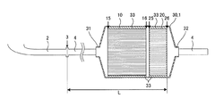
FIG. 1 is a cross-sectional view schematically showing a cross section including a central axis in a cell extending direction of an embodiment of the exhaust gas purifying apparatus of the present invention. FIG. 2 is a perspective view schematically showing a honeycomb catalyst body constituting one embodiment of the exhaust gas purifying apparatus of the present invention. FIG. 3 is a perspective view schematically showing a honeycomb filter constituting one embodiment of the exhaust gas purifying apparatus of the present invention.
本発明の排ガス浄化装置の一実施形態は、図2に示すような、排ガスの流路となる流入側の端面15から流出側の端面16まで延びる複数のセル12を区画形成する隔壁11を有する第一のハニカム構造体13、及び第一のハニカム構造体13の隔壁11に担持された三元触媒を備えたハニカム触媒体10と、図3に示すような、排ガスの流路となる流入側の端面25から流出側の端面26まで延びる複数のセル22を区画形成する隔壁21を有する第二のハニカム構造体23、及び流入側の開口端部が封止されたセル(流出セル22b)と流出側の開口端部が封止されたセル(流入セル22a)とが交互に配置されるように第二のハニカム構造体23のセル22の開口端部を互い違いに封止する目封止部24を備えたハニカムフィルタ20と、図1に示すような、エンジン排気マニホルドの出口側に接続される流入口32、及び流入口32から流入した排ガスを流出する流出口33を有し、ハニカム触媒体10及びハニカムフィルタ20をその内部のガス通路内に保持する筒状の缶体30と、から構成されてなる排ガス浄化装置1である。
One embodiment of the exhaust gas purifying apparatus of the present invention has a
そして、図1に示すように、本実施形態の排ガス浄化装置1を構成するハニカム触媒体10が缶体30の流入口31側に位置し、ハニカムフィルタ20が缶体30の流出口32側に位置すると共に、ハニカム触媒体10の流入側の端面15が缶体30の流入口31側を向き、ハニカムフィルタ20の流出側の端面26が缶体30の流出口32側を向くように、缶体30の内部に配置されている。
As shown in FIG. 1, the
また、本実施形態の排ガス浄化装置においては、ハニカム触媒体10のセル12の延びる方向の長さ(以下、単に「ハニカム触媒体の長さ」ともいう)が、ハニカムフィルタ20のセル22の延びる方向の長さ(以下、単に「ハニカムフィルタの長さ」ともいう)に対して2.0〜10.0倍の長さであり、ハニカムフィルタ20の長さが、ハニカムフィルタ20の外径に対して0.1〜0.5倍の長さであり、ハニカム触媒体10のセル密度がハニカムフィルタ20のセル密度より大である。
Further, in the exhaust gas purification apparatus of the present embodiment, the length of the
本実施形態の排ガス浄化装置1は、上述のような構成を有することにより、圧力損失の増加が少なく、且つ、直噴ガソリンエンジンの始動直後でも排ガスを高効率で浄化することができると共に、粒子状物質を高効率で捕集することができる。特に、エンジン排気マニホルドの出口から1m以内、即ち、エンジン直下に設置されることにより、エンジン始動直後でも高温の排ガスが本実施形態の排ガス浄化装置1に流入するため、ハニカムフィルタ20で捕集される粒子状物質は燃焼され易く、ハニカムフィルタ20内に堆積し難い。そのため、ハニカムフィルタ20は粒子状物質の堆積による圧力損失の増大が少なく、更に、粒子状物質が継続的に燃焼されることから、粒子状物質を長期間保持する必要が無いため、ハニカムフィルタ20のセル22の延びる方向の長さを短くすることができ、初期圧力損失を低減することができる。
The exhaust
本実施形態の排ガス浄化装置1において、ハニカム触媒体10の長さは、ハニカムフィルタ20の長さに対して、2.0〜10.0倍の長さであり、2.0〜5.0倍の長さであることが好ましく、2.0〜3.0倍の長さであることが更に好ましく、2.0〜2.5倍の長さであることが特に好ましい。ハニカム触媒体及びハニカムフィルタの長さが上述の数値範囲内であることにより、本実施形態の排ガス浄化装置1は、直噴ガソリンエンジンの排気系に設置した場合でも、圧力損失の増加が少なく、且つ、エンジン始動直後でも排ガスを高効率で浄化することができると共に、粒子状物質を高効率で捕集することができる。ハニカム触媒体10の長さが、ハニカムフィルタ20の長さに対して、2.0倍未満であると、即ち、ハニカム触媒体10の長さが短すぎるか、又はハニカムフィルタ20の長さが長すぎると、ハニカム触媒体10の長さが短いために、排ガスが十分に浄化されず、また、ハニカムフィルタ20が長いために、初期圧力損失が増加してしまうおそれがある。一方、ハニカム触媒体10の長さが、ハニカムフィルタ20の長さに対して、10.0倍超であると、即ち、ハニカム触媒体10の長さが長すぎるか、又はハニカムフィルタ20の長さが短すぎると、ハニカム触媒体10の長さが長いために、初期圧力損失が増加し、また、ハニカムフィルタ20の長さが短すぎるために、粒子状物質が燃焼される前にハニカムフィルタ20内に堆積し圧力損失が増大してしまうおそれがある。
In the exhaust
また、ハニカム触媒体10のセル密度をハニカムフィルタ20のセル密度より大とすることにより、排ガスの流路の上流側のハニカム触媒体10では、排ガスがハニカム触媒体10の三元触媒と接触する面積を大きくすることができるため、より多くの三元触媒を活性化させることができ、排ガスを効率的に浄化することができる。一方、排ガスの流路の下流側のハニカムフィルタ20は、初期圧力損失が比較的大きいウォールフロー型のフィルタであるが、セル密度を小さくすることにより、初期圧力損失を低減させることができる。
Further, by making the cell density of the
なお、本明細書中、ハニカム構造体(ハニカム触媒体及びハニカムフィルタを含む)の「外径」とは、ハニカム構造体の底面内に描くことができる線分のうち最も長い線分の長さ(最長径)のことを意味する。即ち、「ハニカム構造体の外径」とは、例えば、ハニカム構造体の全体形状が円筒形状である場合は、円(底面)の直径を意味し、ハニカム構造体の全体形状が正四角柱状である場合は、正方形(底面)の対角線の長さを意味し、ハニカム構造体の全体形状が六角柱状である場合は、六角形(底面)の最も長い対角線の長さを意味する。 In this specification, the “outer diameter” of the honeycomb structure (including the honeycomb catalyst body and the honeycomb filter) is the length of the longest line segment that can be drawn in the bottom surface of the honeycomb structure. It means (longest diameter). That is, the “outer diameter of the honeycomb structure” means, for example, the diameter of a circle (bottom surface) when the entire shape of the honeycomb structure is a cylindrical shape, and the entire shape of the honeycomb structure is a regular quadrangular prism shape. In some cases, it means the length of the diagonal line of the square (bottom surface), and when the overall shape of the honeycomb structure is a hexagonal column shape, it means the length of the longest diagonal line of the hexagonal shape (bottom surface).
また、本明細書中、「初期圧力損失」とは、ハニカム構造体に粒子状物質が堆積していない状態での圧力損失を意味する。ここでいう「ハニカム構造体」には、後述する第一及び第二のハニカム構造体、並びにハニカム触媒体及びハニカムフィルタが含まれるものとする。以下、単に「ハニカム構造体」というときも同様である。 Further, in this specification, “initial pressure loss” means pressure loss in a state where particulate matter is not deposited on the honeycomb structure. Here, the “honeycomb structure” includes first and second honeycomb structures, a honeycomb catalyst body, and a honeycomb filter, which will be described later. Hereinafter, the same applies to the “honeycomb structure”.
本実施形態の排ガス浄化装置1においては、ハニカム触媒体10の外径はハニカムフィルタ20の外径以下であることが好ましく、ハニカム触媒体10の外径とハニカムフィルタ20の外径が等しいことがより好ましい。本実施形態の排ガス浄化装置1においては、このように構成されることによって、缶体内の排ガスの流路が狭められることなく浄化対象となる排ガスが通過でき、初期圧力損失の増加を良好に抑制することができる。
In the exhaust
また、本実施形態の排ガス浄化装置1においては、ハニカム触媒体10が缶体30の流入口31側に位置し、ハニカムフィルタ20が缶体30の流出口32側に位置すると共に、ハニカム触媒体10の流入側の端面15が缶体30の流入口31側を向き、ハニカムフィルタ20の流出側の端面26が缶体30の流出口32側を向くように、缶体の内部に配置されていれば良いが、ハニカム触媒体10の流出側の端面16の少なくとも一部がハニカムフィルタ20の流入側の端面25の少なくとも一部と対向していることが好ましく、ハニカム触媒体10の流出側の端面16の全部がハニカムフィルタ20の流入側の端面25と対向していることがより好ましい。本実施形態の排ガス浄化装置1は、このように構成されることによって、ハニカム触媒体10の流出側の端面16から排出されたより多くの排ガスが、流路を曲げることなく直接ハニカムフィルタ20の流入側の端面25へ到達することができるため、ハニカム触媒体10とハニカムフィルタ20の間での圧力損失を抑制することができる。
Further, in the exhaust
なお、端面同士が「対向する」とは、端面同士が平行(ハニカム触媒体及びハニカムフィルタのセルの延びる方向が平行)な状態で端面同士が向かい合うことのみを意味するものではなく、端面同士が平行でない状態で端面同士が向かい合うことも含まれる。即ち、それぞれのセルの延びる方向を含む平面において、互いのセルの延びる方向が、60°未満で傾いた状態であっても、端面同士が向かい合っている場合には、端面同士が対向しているものとする。そして、「ハニカム触媒体の流出側の端面の少なくとも一部がハニカムフィルタの流入側の端面の少なくとも一部と対向している」とは、ハニカムフィルタの流入側の端面の少なくとも一部が、ハニカム触媒体の流出側の端面をセルの延びる方向に平行移動した際の軌跡と重なるように、ハニカム触媒体及びハニカムフィルタが配置されている状態を意味する。更に、「ハニカム触媒体の流出側の端面の全部がハニカムフィルタの流入側の端面と対向している」とは、ハニカムフィルタの流入側の端面の全部が、ハニカム触媒体の流出側の端面をセルの延びる方向に平行移動した際の軌跡と重なるように、ハニカム触媒体及びハニカムフィルタが配置されている状態を意味する。 Note that the term “facing” the end faces does not mean that the end faces face each other in a state where the end faces are parallel (the extending direction of the cells of the honeycomb catalyst body and the honeycomb filter is parallel). It also includes that the end faces face each other in a non-parallel state. That is, in the plane including the extending direction of each cell, even if the extending direction of each cell is inclined at less than 60 °, the end surfaces face each other when the end surfaces face each other. Shall. And, “at least a part of the end face on the outflow side of the honeycomb catalyst body is opposed to at least a part of the end face on the inflow side of the honeycomb filter” means that at least a part of the end face on the inflow side of the honeycomb filter is This means that the honeycomb catalyst body and the honeycomb filter are arranged so as to overlap the trajectory when the end face on the outflow side of the catalyst body is translated in the cell extending direction. Further, “all the end face on the outflow side of the honeycomb catalyst body is opposite to the end face on the inflow side of the honeycomb filter” means that all the end faces on the inflow side of the honeycomb filter are on the end face on the outflow side of the honeycomb catalyst body. It means a state in which the honeycomb catalyst body and the honeycomb filter are arranged so as to overlap with the trajectory when translated in the cell extending direction.
更に、本実施形態の排ガス浄化装置1においては、ハニカム触媒体10のセル12の延びる方向とハニカムフィルタ20のセル22の延びる方向とが平行であることが更に好ましく、ハニカム触媒体10のセル12の延びる方向の中心軸(以下、単に「ハニカム触媒体の中心軸」ともいう)とハニカムフィルタ20のセル22の延びる方向の中心軸(以下、単に「ハニカムフィルタの中心軸」ともいう)とが同一直線上に位置することが特に好ましい。本実施形態の排ガス浄化装置1は、このように構成されることによって、ハニカム触媒体10の流出側の端面16から排出された排ガスが、ハニカムフィルタ20の流入側の端面25に開口した流入セル22aの内部へ、流路を曲げることなく侵入することができるため、ハニカムフィルタ20流入時の圧力損失を良好に抑制することができる。特に、ハニカム触媒体の中心軸とハニカムフィルタの中心軸とが同一直線上にある場合、前述のハニカム触媒体10とハニカムフィルタ20の間での圧力損失だけでなく、ハニカムフィルタ20流入時の圧力損失をも抑制することができるため、ハニカム触媒体10とハニカムフィルタ20との位置関係により生じる圧力損失を、最も効果的に抑制することができる。また、排ガスがハニカム触媒体10を通過する際、炭化水素や一酸化炭素の酸化反応により排ガスの温度が上昇し、且つ、この高温の排ガスが缶体30の内壁に衝突せずに直接ハニカムフィルタ20内へ流入するため、熱が缶体30へ逃げることを防ぐことができると共に、ハニカムフィルタ20内の温度を上昇させ、堆積した粒子状物質を効率よく燃焼させることができる。
Furthermore, in the exhaust
また、本実施形態の排ガス浄化装置1は、ハニカム触媒体10とハニカムフィルタ20との間に1〜30mmの隙間が設けられていることが好ましく、2〜20mmの隙間が設けられていることが更に好ましく、2〜10mmの隙間が設けられていることが特に好ましい。ハニカム触媒体10とハニカムフィルタ20との間の隙間が1mm未満であると、本実施形態の排ガス浄化装置1は、自動車に搭載された際、走行中の振動や、エンジンから伝わる振動等により、ハニカム触媒体10の流出側の端面16とハニカムフィルタ20の流入側の端面25とが接触し、ハニカム触媒体10、ハニカムフィルタ20、又はその両方が破損、磨耗等してしまうことがある。一方、隙間が30mm超であると、ハニカム触媒体10の流出側の端面16から排出された排ガスの温度が、この隙間を通過している間に下がってしまい、ハニカムフィルタ20内の粒子状物質を十分に燃焼させることができず、圧力損失が増大してしまうおそれがある。
Further, in the exhaust
以下、本実施形態の排ガス浄化装置の各構成要素について、更に具体的に説明する。 Hereinafter, each component of the exhaust gas purifying apparatus of the present embodiment will be described more specifically.
[1−1]ハニカム触媒体:
本実施形態の排ガス浄化装置を構成するハニカム触媒体は、図2に示すように、第一のハニカム構造体13、及び第一のハニカム構造体13の隔壁11に担持された三元触媒を備えたものである。
[1-1] Honeycomb catalyst body:
As shown in FIG. 2, the honeycomb catalyst body constituting the exhaust gas purifying apparatus of the present embodiment includes a
[1−1−1]第一のハニカム構造体:
第一のハニカム構造体(ハニカム触媒体用のハニカム構造体)は、図2に示すように、排ガスの流路となる流入側の端面15から流出側の端面16まで延びる複数のセル12を区画形成する隔壁11を有するものである。なお、図2に示す第一のハニカム構造体は、最外周に位置する外周壁17を有するものである。
[1-1-1] First honeycomb structure:
As shown in FIG. 2, the first honeycomb structure (honeycomb structure for the honeycomb catalyst body) defines a plurality of
第一のハニカム構造体の全体形状としては、特に制限はなく、例えば、図2に示すような円筒(円柱)形状や楕円筒(楕円柱)形状の他、三角柱、四角柱、六角柱等の多角柱形状、底面が不定形である柱形状等を挙げることができる。 The overall shape of the first honeycomb structure is not particularly limited. For example, in addition to a cylindrical (column) shape or an elliptic cylinder (elliptical column) shape as shown in FIG. 2, a triangular column, a quadrangular column, a hexagonal column, etc. Examples thereof include a polygonal column shape and a column shape whose bottom is irregular.
第一のハニカム構造体の長さは、60〜160mmであることが好ましく、70〜150mmであることが更に好ましく、80〜140mmであることが特に好ましい。第一のハニカム構造体の長さが、60mm未満であると、ハニカム触媒体として排ガスを十分に浄化することができないおそれがある。一方、第一のハニカム構造体の長さが160mm超であると、初期圧力損失が増加してしまう傾向にある。 The length of the first honeycomb structure is preferably 60 to 160 mm, more preferably 70 to 150 mm, and particularly preferably 80 to 140 mm. If the length of the first honeycomb structure is less than 60 mm, the exhaust gas may not be sufficiently purified as the honeycomb catalyst body. On the other hand, if the length of the first honeycomb structure exceeds 160 mm, the initial pressure loss tends to increase.
第一のハニカム構造体の外径としては、特に制限はないが、80〜180mmであることが好ましく、80〜150mmであることが更に好ましく、100〜150mmであることが特に好ましい。第一のハニカム構造体の外径が80mm未満であると、排ガス処理装置のハニカム触媒体部分の排ガスの通路が狭く、初期圧力損失が増加してしまい好ましくない。一方、第一のハニカム構造体の外径が180mm超であると、排ガス処理装置(缶体)自体も大きくなるため、質量が増加すると共に設計上の問題も生じてしまい好ましくない。 The outer diameter of the first honeycomb structure is not particularly limited, but is preferably 80 to 180 mm, more preferably 80 to 150 mm, and particularly preferably 100 to 150 mm. If the outer diameter of the first honeycomb structure is less than 80 mm, the exhaust gas passage in the honeycomb catalyst body portion of the exhaust gas treatment apparatus is narrow, and the initial pressure loss increases, which is not preferable. On the other hand, if the outer diameter of the first honeycomb structure is more than 180 mm, the exhaust gas treatment device (can body) itself becomes large, which increases the mass and causes design problems.
第一のハニカム構造体の外径に対する、第一のハニカム構造体の長さの比の値(長さ/外径)は、0.5〜1.5であることが好ましく、0.7〜1.4であることが更に好ましく、1.0〜1.2であることが特に好ましい。第一のハニカム構造体の長さ/外径の比の値が上述の数値範囲内であることにより、本実施形態の排ガス浄化装置のハニカム触媒体として好ましいサイズ及び形状とすることができる。 The ratio of the length of the first honeycomb structure to the outer diameter of the first honeycomb structure (length / outer diameter) is preferably 0.5 to 1.5, preferably 0.7 to It is more preferable that it is 1.4, and it is especially preferable that it is 1.0-1.2. When the value of the ratio of the length / outer diameter of the first honeycomb structure is within the above-described numerical range, a preferable size and shape can be obtained as the honeycomb catalyst body of the exhaust gas purification apparatus of the present embodiment.
第一のハニカム構造体に形成されたセルの形状(セルの延びる方向に対して垂直な断面の形状)としては、特に制限なく従来公知のセルの形状を用いることができ、例えば、四角形、五角形、六角形、八角形、三角形、円形、楕円形等の形状が好ましく、その他不定形であってもよい。これらの形状の中でも、円形又は四角以上の多角形の形状がより好ましい。このようなセルの形状であると、角の部分に触媒が厚付きすることを抑制することができ、隔壁に触媒を均一に担持させることができる。また、セル密度、開口率等を考慮すると、セルの形状としては、四角形、六角形が好ましい。なお、セルの形状は、一種類だけでなく、複数種の形状が組み合わされていても良い。 As the shape of the cell formed in the first honeycomb structure (the shape of the cross section perpendicular to the cell extending direction), a conventionally known cell shape can be used without particular limitation. , Hexagons, octagons, triangles, circles, ellipses and the like are preferable, and other irregular shapes may be used. Among these shapes, a circular shape or a polygonal shape having a square shape or more is more preferable. With such a cell shape, the catalyst can be prevented from being thickened at the corners, and the catalyst can be uniformly supported on the partition walls. In consideration of cell density, aperture ratio, and the like, the cell shape is preferably a square or a hexagon. Note that the shape of the cell is not limited to one type, and a plurality of types of shapes may be combined.
第一のハニカム構造体のセル密度は、62.0〜186セル/cm2であることが好ましく、62.0〜100セル/cm2であることが更に好ましく、62.0〜80.0セル/cm2であることが特に好ましい。第一のハニカム構造体のセル密度が上述の数値範囲内であると、排ガスと第一のハニカム構造体の隔壁及びこの隔壁に担持される三元触媒との接触面積を大きくすることができると共に、第一のハニカム構造体の圧力損失が過度に増加することを抑制することができる。このため、排ガスの温度を更に上げて触媒活性温度へより早く到達させることができ、排ガスを効率的に浄化することができる。 The cell density of the first honeycomb structure, more preferably from preferably from 62.0 to 186 cells / cm 2, is from 62.0 to 100 cells / cm 2, from 62.0 to 80.0 cells / Cm 2 is particularly preferred. When the cell density of the first honeycomb structure is within the above numerical range, the contact area between the exhaust gas and the partition walls of the first honeycomb structure and the three-way catalyst supported on the partition walls can be increased. It is possible to suppress an excessive increase in the pressure loss of the first honeycomb structure. For this reason, the temperature of the exhaust gas can be further increased to reach the catalyst activation temperature earlier, and the exhaust gas can be efficiently purified.
第一のハニカム構造体の隔壁の厚さは、0.051〜0.102mmであることが好ましく、0.051〜0.095mmであることが更に好ましく、0.051〜0.080mmであることが特に好ましい。第一のハニカム構造体の隔壁の厚さを上述の数値範囲内とすることにより、後述する三元触媒を担持(コート)させた場合でも、十分な排ガスの流路を確保することができ、初期圧力損失の増加を抑制することができる。また、第一のハニカム構造体の隔壁の厚さを上述の数値範囲内とすることにより、第一のハニカム構造体の全熱容量を低減させることができるため、排ガスが持つ熱や触媒反応の反応熱により第一のハニカム構造体の温度が上昇し易く、触媒活性温度により早く到達させることができる。 The thickness of the partition walls of the first honeycomb structure is preferably 0.051 to 0.102 mm, more preferably 0.051 to 0.095 mm, and 0.051 to 0.080 mm. Is particularly preferred. By setting the thickness of the partition walls of the first honeycomb structure within the above numerical range, even when a three-way catalyst described later is supported (coated), a sufficient exhaust gas flow path can be secured, An increase in initial pressure loss can be suppressed. Moreover, since the total heat capacity of the first honeycomb structure can be reduced by setting the partition wall thickness of the first honeycomb structure within the above numerical range, the heat of exhaust gas and the reaction of the catalytic reaction The temperature of the first honeycomb structure easily rises due to heat, and can reach the catalyst activation temperature earlier.
第一のハニカム構造体の材質としては、コージェライト、ムライト、アルミナ、炭化珪素、及びチタン酸アルミニウムからなる群より選択される少なくとも一種を含んでいることが好ましい。 The material of the first honeycomb structure preferably includes at least one selected from the group consisting of cordierite, mullite, alumina, silicon carbide, and aluminum titanate.
第一のハニカム構造体の隔壁の気孔率は、20〜50%であることが好ましく、第一のハニカム構造体の隔壁の平均気孔径は1〜6μmであることが好ましい。第一のハニカム構造体の隔壁の気孔率及び平均気孔径を、上述の数値範囲内とすることにより、隔壁表面への触媒の密着性を向上させ、触媒を剥がれ難くすることができる。なお、本明細書中、「気孔率」及び「平均細孔径」は、水銀圧入法により測定した気孔率及び平均細孔径を意味するものとする。 The porosity of the partition walls of the first honeycomb structure is preferably 20 to 50%, and the average pore diameter of the partition walls of the first honeycomb structure is preferably 1 to 6 μm. By setting the porosity and average pore diameter of the partition walls of the first honeycomb structure within the above numerical range, the adhesion of the catalyst to the partition surface can be improved and the catalyst can be made difficult to peel off. In the present specification, “porosity” and “average pore diameter” mean the porosity and average pore diameter measured by mercury porosimetry.
〔第一のハニカム構造体の製造方法〕
以下、第一のハニカム構造体の製造方法について説明する。
[First honeycomb structure manufacturing method]
Hereinafter, a method for manufacturing the first honeycomb structure will be described.
第一のハニカム構造体の製造方法においては、まず、セラミック原料を含有するセラミック成形原料を調製することが好ましい。セラミック成形原料に含有されるセラミック原料としては、コージェライト化原料、コージェライト、ムライト、アルミナ、炭化珪素、及びチタン酸アルミニウムからなる群から選択された少なくとも1種を含むものであることが好ましく、コージェライト化原料、コージェライト、ムライト、アルミナ、炭化珪素、及びチタン酸アルミニウムからなる群から選択された少なくとも1種であることが更に好ましく、コージェライト化原料、コージェライト、ムライト、アルミナ、炭化珪素、及びチタン酸アルミニウムからなる群から選択された1種であることが特に好ましい。なお、コージェライト化原料とは、シリカが42〜56質量%、アルミナが30〜45質量%、マグネシアが12〜16質量%の範囲に入る化学組成となるように配合されたセラミックス原料であって、焼成されてコージェライトになるものである。 In the first method for manufacturing a honeycomb structure, it is preferable to first prepare a ceramic forming raw material containing a ceramic raw material. The ceramic raw material contained in the ceramic forming raw material is preferably one containing at least one selected from the group consisting of cordierite forming raw material, cordierite, mullite, alumina, silicon carbide, and aluminum titanate. More preferably, the raw material is cordierite, mullite, alumina, silicon carbide, and at least one selected from the group consisting of aluminum titanate, cordierite raw material, cordierite, mullite, alumina, silicon carbide, and Particularly preferred is one selected from the group consisting of aluminum titanates. The cordierite forming raw material is a ceramic raw material blended so as to have a chemical composition that falls within a range of 42 to 56% by mass of silica, 30 to 45% by mass of alumina, and 12 to 16% by mass of magnesia. It is fired to become cordierite.
コージェライト化原料としては、具体的には、シリカ源成分、マグネシア源成分、及びアルミナ源成分を用いることが好ましい。 Specifically, as a cordierite forming raw material, it is preferable to use a silica source component, a magnesia source component, and an alumina source component.
シリカ源成分としては、石英、カオリン、溶融シリカ等を挙げることができる。また、シリカ源成分の粒径は100〜150μmであることが好ましい。 Examples of the silica source component include quartz, kaolin, and fused silica. Moreover, it is preferable that the particle size of a silica source component is 100-150 micrometers.
マグネシア(MgO)源成分としては、タルク、マグネサイト等を挙げることができる。これらの中でも、タルクが好ましい。タルクは、コージェライト化原料中37〜43質量%含有させることが好ましい。タルクの平均粒子径は、5〜50μmであることが好ましく、10〜40μmであることが更に好ましい。また、マグネシア源成分は、不純物としてFe2O3、CaO、Na2O、K2O等を含有していてもよい。 Examples of the magnesia (MgO) source component include talc and magnesite. Among these, talc is preferable. Talc is preferably contained in an amount of 37 to 43% by mass in the cordierite forming raw material. The average particle diameter of talc is preferably 5 to 50 μm, and more preferably 10 to 40 μm. Further, the magnesia source component may contain Fe 2 O 3 , CaO, Na 2 O, K 2 O and the like as impurities.
アルミナ源成分としては、不純物が少ないという点で、酸化アルミニウム及び水酸化アルミニウムからなる群から選択される少なくとも一種であることが好ましい。水酸化アルミニウムを用いる場合、水酸化アルミニウムは、コージェライト化原料中、10〜30質量%含有されることが好ましい。また、酸化アルミニウムを用いる場合、酸化アルミニウムは、コージェライト化原料中、1〜45質量%含有されることが好ましい。また、水酸化アルミニウムと酸化アルミニウムとを混合して使用する場合、コージェライト化原料中、水酸化アルミニウムは5〜25質量%含有され、酸化アルミニウムは10〜40質量%含有されることが好ましい。 The alumina source component is preferably at least one selected from the group consisting of aluminum oxide and aluminum hydroxide in that there are few impurities. When using aluminum hydroxide, it is preferable that 10-30 mass% aluminum hydroxide is contained in the cordierite forming raw material. Moreover, when using aluminum oxide, it is preferable that 1 to 45 mass% of aluminum oxide is contained in the cordierite-forming raw material. Moreover, when mixing and using aluminum hydroxide and aluminum oxide, it is preferable that 5-25 mass% aluminum hydroxide is contained in a cordierite-forming raw material, and 10-40 mass% aluminum oxide is contained.
セラミック成形原料は、上記セラミック原料に、分散媒、造孔材、有機バインダ、分散剤、界面活性剤等を混合して調製することが好ましい。それぞれの原料の混合比は、セラミック原料100質量部に対して、分散媒10〜40質量部、造孔材0〜40質量部、有機バインダ3〜8質量部、分散剤0.1〜2質量部、界面活性剤0.1〜2質量部であることが好ましい。 The ceramic forming raw material is preferably prepared by mixing the ceramic raw material with a dispersion medium, a pore former, an organic binder, a dispersant, a surfactant and the like. The mixing ratio of the respective raw materials is 10 to 40 parts by weight of the dispersion medium, 0 to 40 parts by weight of the pore former, 3 to 8 parts by weight of the organic binder, and 0.1 to 2 parts by weight of the dispersant with respect to 100 parts by weight of the ceramic raw material Part, surfactant is preferably 0.1 to 2 parts by weight.
分散媒としては、水を挙げることができる。造孔材としては、焼成後に気孔となるものであれば特に限定されるものではなく、例えば、澱粉、発泡樹脂、吸水性樹脂、シリカゲル、炭素(コークス)等を挙げることができる。有機バインダとしては、ヒドロキシプロピルメチルセルロース、メチルセルロース、ヒドロキシエチルセルロース、カルボキシルメチルセルロース、ポリビニルアルコール等を挙げることができる。分散剤としては、デキストリンや、エチレングリコール等のポリアルコール等を挙げることができる。界面活性剤としては、例えば、脂肪酸石鹸等を挙げることができる。 An example of the dispersion medium is water. The pore former is not particularly limited as long as it becomes pores after firing, and examples thereof include starch, foamed resin, water absorbent resin, silica gel, carbon (coke) and the like. Examples of the organic binder include hydroxypropyl methylcellulose, methylcellulose, hydroxyethylcellulose, carboxymethylcellulose, and polyvinyl alcohol. Examples of the dispersant include dextrin and polyalcohols such as ethylene glycol. Examples of the surfactant include fatty acid soap.
次に、調製したセラミック成形原料を、ニーダー、真空土練機等を用いて混練し、坏土を形成することが好ましい。 Next, it is preferable to knead the prepared ceramic forming raw material using a kneader, a vacuum kneader or the like to form a clay.
次に、坏土を成形して、流体の流路となる複数のセルを区画形成する隔壁と最外周に位置する外周壁とを備える筒状のハニカム成形体を成形することが好ましい。坏土を成形する方法としては、押出成形法、射出成形法、プレス成形法等を挙げることができる。これらの中では、連続成形が容易であり、また、例えばコージェライト結晶を配向させることができるという特徴を有していることより、押出成形法が好ましい。押出成形法は、真空土練機、ラム式押出成形機、2軸スクリュー式連続押出成形機等の装置を用いて実施することができる。例えば、所望のセル形状、隔壁厚さ、セル密度を有する口金を用いて押出成形してハニカム成形体を形成することが好ましい。口金の材質としては、摩耗し難い超硬合金が好ましい。 Next, it is preferable to mold a clay and form a tubular honeycomb formed body including partition walls that define a plurality of cells that serve as fluid flow paths and an outer peripheral wall located at the outermost periphery. Examples of the method for molding the kneaded material include an extrusion molding method, an injection molding method, and a press molding method. Among these, the extrusion molding method is preferable because it has a feature that continuous molding is easy and, for example, cordierite crystals can be oriented. The extrusion molding method can be carried out using an apparatus such as a vacuum kneader, a ram type extruder, or a twin screw type continuous extruder. For example, it is preferable to form a honeycomb formed body by extrusion using a die having a desired cell shape, partition wall thickness, and cell density. As the material of the die, a cemented carbide which does not easily wear is preferable.
上記成形後に、得られたハニカム成形体を乾燥させてもよい。乾燥方法は、特に限定されないが、例えば、熱風乾燥、マイクロ波乾燥、誘電乾燥、減圧乾燥、真空乾燥、凍結乾燥を挙げることができ、なかでも、誘電乾燥、マイクロ波乾燥又は熱風乾燥を単独で又はこれらを組合せて行うことが好ましい。また、乾燥条件としては、乾燥温度80〜150℃、乾燥時間5分〜2時間とすることが好ましい。 After the above forming, the obtained honeycomb formed body may be dried. The drying method is not particularly limited, and examples thereof include hot air drying, microwave drying, dielectric drying, reduced pressure drying, vacuum drying, and freeze drying, and among them, dielectric drying, microwave drying, or hot air drying alone. Or it is preferable to carry out in combination. The drying conditions are preferably a drying temperature of 80 to 150 ° C. and a drying time of 5 minutes to 2 hours.
次に、得られたハニカム成形体を焼成してハニカム焼成体(第一のハニカム構造体)を得ることが好ましい。 Next, it is preferable to fire the obtained honeycomb formed body to obtain a honeycomb fired body (first honeycomb structure).
また、ハニカム成形体を焼成(本焼成)する前には、そのハニカム成形体を仮焼することが好ましい。仮焼は、脱脂のために行うものであり、その方法は、特に限定されるものではなく、ハニカム成形体中の有機物(有機バインダ、分散剤、造孔材等)を除去することができればよい。一般に、有機バインダの燃焼温度は100〜300℃程度、造孔材の燃焼温度は200〜800℃程度であるので、仮焼の条件としては、酸化雰囲気において、200〜1000℃程度で、3〜100時間程度加熱することが好ましい。 Further, before firing (main firing) the honeycomb formed body, it is preferable to calcine the honeycomb formed body. The calcination is performed for degreasing, and the method is not particularly limited as long as the organic matter (organic binder, dispersant, pore former, etc.) in the honeycomb formed body can be removed. . In general, the combustion temperature of the organic binder is about 100 to 300 ° C., and the combustion temperature of the pore former is about 200 to 800 ° C. Therefore, the calcining conditions are about 200 to 1000 ° C. in an oxidizing atmosphere, 3 to It is preferable to heat for about 100 hours.
ハニカム成形体の焼成(本焼成)は、仮焼したハニカム成形体を構成する成形原料を焼結させて緻密化し、所定の強度を確保するために行われる。焼成条件(温度、時間、雰囲気)は、成形原料の種類により異なるため、その種類に応じて適当な条件を選択すればよい。例えば、コージェライト化原料を使用している場合には、焼成温度は、1410〜1440℃が好ましい。また、焼成時間は、3〜15時間が好ましい。 The firing (main firing) of the honeycomb formed body is performed in order to sinter and densify the forming raw material constituting the calcined honeycomb formed body to ensure a predetermined strength. Since the firing conditions (temperature, time, atmosphere) vary depending on the type of molding raw material, appropriate conditions may be selected according to the type. For example, when a cordierite forming raw material is used, the firing temperature is preferably 1410 to 1440 ° C. The firing time is preferably 3 to 15 hours.
第一のハニカム構造体の外周壁は、成形時に第一のハニカム構造体と一体的に形成される外周壁(成形一体壁)であっても良く、成形後に、第一のハニカム構造体の外周を研削して所定形状とし、セメント等で形成された外周壁(セメントコート壁)であっても良い。外周壁が成形一体壁である場合、外周壁の材質は第一のハニカム構造体の材質と同じ材質であることが好ましい。また、外周壁がセメントコート壁である場合、セメントコート壁の材質としては、共素地にガラス等のフラックス成分を加えた材料等を挙げることができる。また、外周壁の厚さは、0.5〜1.5mmであることが好ましい。 The outer peripheral wall of the first honeycomb structure may be an outer peripheral wall (molded integral wall) formed integrally with the first honeycomb structure at the time of molding. The outer peripheral wall (cement coat wall) formed by cement or the like may be used. When the outer peripheral wall is a molded integrated wall, the outer peripheral wall is preferably made of the same material as that of the first honeycomb structure. Further, when the outer peripheral wall is a cement coated wall, examples of the material of the cement coated wall include a material obtained by adding a flux component such as glass to a common substrate. Moreover, it is preferable that the thickness of an outer peripheral wall is 0.5-1.5 mm.
[1−1−2]三元触媒:
三元触媒は、排ガス中に含まれる炭化水素(HC)、一酸化炭素(CO)、窒素酸化物(NOX)を主に浄化する触媒である。
[1-1-2] Three-way catalyst:
The three-way catalyst is a catalyst that mainly purifies hydrocarbons (HC), carbon monoxide (CO), and nitrogen oxides (NO x ) contained in the exhaust gas.
ハニカムフィルタの隔壁に担持される三元触媒としては、例えば、白金(Pt)、パラジウム(Pd)、ロジウム(Rh)等の貴金属を、例えば、アルミナ、チタニア、シリカ、酸化セリウム、ジルコニア、酸化タングステン、ゼオライト、遷移金属酸化物、希土類酸化物、又はこれらの混合物等の耐熱性無機酸化物からなる担体に担持させたものを用いることができる。 Examples of the three-way catalyst supported on the partition walls of the honeycomb filter include noble metals such as platinum (Pt), palladium (Pd), and rhodium (Rh), and examples include alumina, titania, silica, cerium oxide, zirconia, and tungsten oxide. , Zeolite, transition metal oxide, rare earth oxide, or a support made of a heat-resistant inorganic oxide such as a mixture thereof can be used.
ハニカム触媒体の隔壁に担持される三元触媒の量(三元触媒コート量)としては、100〜400g/Lであることが好ましく、120〜300g/Lであることが更に好ましく、150〜250g/Lであることが特に好ましい。三元触媒のコート量が400g/L超であると、ハニカム触媒体が排ガスを浄化する性能が向上することが期待できるが、排ガスの流路であるセルの断面積が小さくなり、初期圧力損失が増大してしまうため好ましくない。一方、三元触媒のコート量が100g/L未満であると、ハニカム触媒体が排ガスを十分に浄化することができなくなるおそれがある。なお、本明細書中、触媒コート量(g/L)は、ハニカム構造体の単位体積(1L)あたりに担持される触媒の量(g)を示す。 The amount of the three-way catalyst supported on the partition walls of the honeycomb catalyst body (three-way catalyst coating amount) is preferably 100 to 400 g / L, more preferably 120 to 300 g / L, and more preferably 150 to 250 g. / L is particularly preferable. If the coating amount of the three-way catalyst is more than 400 g / L, the honeycomb catalyst body can be expected to improve the performance of purifying the exhaust gas, but the cross-sectional area of the cell that is the exhaust gas flow path is reduced, and the initial pressure loss is reduced. Is not preferable because it increases. On the other hand, if the coating amount of the three-way catalyst is less than 100 g / L, the honeycomb catalyst body may not be able to sufficiently purify the exhaust gas. In the present specification, the catalyst coat amount (g / L) indicates the amount (g) of the catalyst supported per unit volume (1 L) of the honeycomb structure.
三元触媒をハニカム触媒体へ担持(コート)させる方法としては、特に制限はないが、例えば、第一のハニカム構造体の隔壁に対して、三元触媒を含む触媒液をウォッシュコートした後、高温で熱処理して焼き付ける方法、ディッピング法等の従来公知のセラミック膜形成方法を利用して、三元触媒コート用スラリーを第一のハニカム構造体の隔壁に付着させ、乾燥、焼成する方法等によって三元触媒を担持させることができる。 The method for supporting (coating) the three-way catalyst on the honeycomb catalyst body is not particularly limited. For example, after the catalyst solution containing the three-way catalyst is washed on the partition walls of the first honeycomb structure, By using a conventionally known ceramic film forming method such as heat treatment and baking at a high temperature, dipping method, etc., the slurry for three-way catalyst coating is attached to the partition walls of the first honeycomb structure, dried, fired, etc. A three-way catalyst can be supported.
[1−2]ハニカムフィルタ:
本実施形態の排ガス浄化装置を構成するハニカムフィルタは、図3に示すように、第二のハニカム構造体23、及び第二のハニカム構造体23のセル22の開口端部を互い違いに封止する目封止部24を備えたものである。
[1-2] Honeycomb filter:
As shown in FIG. 3, the honeycomb filter constituting the exhaust gas purifying apparatus of the present embodiment alternately seals the
[1−2−1]第二のハニカム構造体:
第二のハニカム構造体(ハニカムフィルタ用のハニカム構造体)は、排ガスの流路となる流入側の端面25から流出側の端面26まで延びる複数のセル22を区画形成する隔壁21を有するものである。なお、図3に示す第二のハニカム構造体は、最外周に位置する外周壁27を有するものである。なお、第二のハニカム構造体は、第一のハニカム構造体の製造方法と同様の方法により製造することができる。
[1-2-1] Second honeycomb structure:
The second honeycomb structure (honeycomb structure for a honeycomb filter) has
なお、上述したように、第二のハニカム構造体の長さ(ハニカムフィルタの長さ)に対して、第一のハニカム構造体の長さ(ハニカム触媒体の長さ)は、2.0〜10.0倍である。第一及び第二のハニカム構造体の長さが上述の関係にあることにより、本実施形態の排ガス浄化装置は、直噴ガソリンエンジンの排気系に設置した場合でも、圧力損失の増加が少なく、且つ、エンジン始動直後でも排ガスを高効率で浄化することができると共に、粒子状物質を高効率で捕集することができる。 As described above, the length of the first honeycomb structure (the length of the honeycomb catalyst body) is 2.0 to 2.0 with respect to the length of the second honeycomb structure (the length of the honeycomb filter). 10.0 times. Because the lengths of the first and second honeycomb structures are in the above-described relationship, the exhaust gas purification device of the present embodiment has little increase in pressure loss even when installed in the exhaust system of a direct injection gasoline engine, Moreover, exhaust gas can be purified with high efficiency even immediately after the engine is started, and particulate matter can be collected with high efficiency.
第二のハニカム構造体の全体形状としては、第一のハニカム構造体と同様に、特に制限はなく、例えば、図2に示すような円筒(円柱)形状や楕円筒(楕円柱)形状の他、三角柱、四角柱、六角柱等の多角柱形状、底面が不定形である柱形状等を挙げることができる。なお、第一のハニカム構造体の端面の形状と第二のハニカム構造体の端面の形状は同じであることが好ましい。 The overall shape of the second honeycomb structure is not particularly limited, as with the first honeycomb structure, and includes, for example, a cylinder (column) shape or an elliptic cylinder (elliptical cylinder) shape as shown in FIG. Polygonal columnar shapes such as a triangular column, a quadrangular column, and a hexagonal column, and a columnar shape whose bottom surface is indefinite. Note that the shape of the end face of the first honeycomb structure and the shape of the end face of the second honeycomb structure are preferably the same.
第二のハニカム構造体の長さは、15〜50mmであることが好ましく、20〜50mmであることが更に好ましく、30〜50mmであることが特に好ましい。第二のハニカム構造体の長さが上述の数値範囲内であることにより、排ガス中の粒子状物質を効率的に捕集することができると共に、圧力損失の増加を抑制することができる。特に、直噴ガソリンエンジンの排ガスを浄化するために本実施形態の排ガス浄化装置を使用する場合には、ディーゼルエンジンの排ガスを浄化するために使用する場合と比較して、第二のハニカム構造体(ハニカムフィルタ)の長さを短くすることができ、圧力損失の増加を抑制することができる。なお、第二のハニカム構造体の長さが50mm超であると、ハニカムフィルタの初期圧力損失が増大してしまうため好ましくない。一方、第二のハニカム構造体の長さが15mm未満であると、粒子状物質が燃焼される前にハニカムフィルタ内に堆積してしまい、圧力損失が増大してしまうおそれがある。 The length of the second honeycomb structure is preferably 15 to 50 mm, more preferably 20 to 50 mm, and particularly preferably 30 to 50 mm. When the length of the second honeycomb structure is within the above numerical range, particulate matter in the exhaust gas can be efficiently collected and an increase in pressure loss can be suppressed. In particular, when the exhaust gas purification device of the present embodiment is used to purify the exhaust gas of a direct injection gasoline engine, the second honeycomb structure is used in comparison with the case of using the exhaust gas purification device of a diesel engine. The length of the (honeycomb filter) can be shortened, and an increase in pressure loss can be suppressed. Note that if the length of the second honeycomb structure exceeds 50 mm, the initial pressure loss of the honeycomb filter increases, which is not preferable. On the other hand, if the length of the second honeycomb structure is less than 15 mm, the particulate matter is deposited in the honeycomb filter before being burned, and the pressure loss may increase.
第二のハニカム構造体の外径としては、特に制限はないが、80〜180mmであることが好ましく、80〜150mmであることが更に好ましく、100〜150mmであることが特に好ましい。第二のハニカム構造体の外径が80mm未満であると、排ガス処理装置のハニカム触媒体部分の排ガスの通路が狭く、初期圧力損失が増加してしまい好ましくない。一方、第二のハニカム構造体の外径が180mm超であると、排ガス処理装置(缶体)自体も大きくなるため、質量が増加すると共に設計上の問題も生じてしまい好ましくない。 The outer diameter of the second honeycomb structure is not particularly limited, but is preferably 80 to 180 mm, more preferably 80 to 150 mm, and particularly preferably 100 to 150 mm. If the outer diameter of the second honeycomb structure is less than 80 mm, the exhaust gas passage in the honeycomb catalyst body portion of the exhaust gas treatment device is narrow and the initial pressure loss increases, which is not preferable. On the other hand, if the outer diameter of the second honeycomb structure is more than 180 mm, the exhaust gas treatment device (can body) itself also becomes large, which increases the mass and causes design problems.
第二のハニカム構造体の外径に対する、第二のハニカム構造体の長さの比の値(長さ/外径)は、0.1〜0.5であり、0.2〜0.5であることが好ましく、0.2〜0.4であることが更に好ましく、0.2〜0.3であることが特に好ましい。第二のハニカム構造体の長さ/外径の比の値が上述の数値範囲内であることにより、本実施形態の排ガス浄化装置のハニカムフィルタとして好ましいサイズ及び形状とすることができる。 The value of the ratio of the length of the second honeycomb structure to the outer diameter of the second honeycomb structure (length / outer diameter) is 0.1 to 0.5, and 0.2 to 0.5. It is preferable that it is 0.2-0.4, and it is especially preferable that it is 0.2-0.3. When the value of the ratio of the length / outer diameter of the second honeycomb structure is within the above numerical range, a preferable size and shape can be obtained for the honeycomb filter of the exhaust gas purification apparatus of the present embodiment.
第二のハニカム構造体に形成されたセルの形状(セルの延びる方向に対して垂直な断面の形状)としては、特に制限なく従来公知のセルの形状を用いることができ、例えば、四角形、五角形、六角形、八角形、三角形、円形、楕円形等の形状が好ましく、その他不定形であってもよい。これらの形状の中でも、円形又は四角以上の多角形の形状がより好ましい。このようなセルの形状であると、セルの内部に、粒子状物質を含む排ガスが流入した場合に、セルを区画形成する隔壁によって、上記粒子状物質を良好に捕集することができる。また、セル密度、開口率等を考慮すると、セルの形状としては、四角形、六角形が好ましい。なお、セルの形状は、一種類だけでなく、複数種の形状が組み合わされていても良い。 As the shape of the cell formed in the second honeycomb structure (the shape of the cross section perpendicular to the cell extending direction), a conventionally known cell shape can be used without any particular limitation. , Hexagons, octagons, triangles, circles, ellipses and the like are preferable, and other irregular shapes may be used. Among these shapes, a circular shape or a polygonal shape having a square shape or more is more preferable. With such a cell shape, when the exhaust gas containing particulate matter flows into the cell, the particulate matter can be well collected by the partition walls that partition the cell. In consideration of cell density, aperture ratio, and the like, the cell shape is preferably a square or a hexagon. Note that the shape of the cell is not limited to one type, and a plurality of types of shapes may be combined.
第二のハニカム構造体のセル密度は、7.75〜46.5セル/cm2であることが好ましく、20.0〜46.5セル/cm2であることが更に好ましく、30.0〜46.5セル/cm2であることが特に好ましい。第二のハニカム構造体のセル密度が上述の数値範囲内であると、粒子状物質の捕集効率を下げることなく、初期圧力損失を低減させることができる。なお、第二のハニカム構造体(ハニカムフィルタ用のハニカム構造体)のセル密度は、第一のハニカム構造体(ハニカム触媒体用のハニカム構造体)のセル密度より小である。 The cell density of the second honeycomb structure, more preferably from preferably from 7.75 to 46.5 cells / cm 2, is 20.0 to 46.5 cells / cm 2, 30.0 46.5 cells / cm 2 are particularly preferred. When the cell density of the second honeycomb structure is within the above numerical range, the initial pressure loss can be reduced without lowering the collection efficiency of the particulate matter. The cell density of the second honeycomb structure (honeycomb structure for honeycomb filter) is smaller than the cell density of the first honeycomb structure (honeycomb structure for honeycomb catalyst body).
第二のハニカム構造体の隔壁の厚さは、0.100〜0.508mmであることが好ましく、0.127〜0.300mmであることが更に好ましく、0.127〜0.200mmであることが特に好ましい。第二のハニカム構造体の隔壁の厚さを上述の数値範囲内とすることにより、後述する酸化触媒を担持(コート)させた場合でも、十分な排ガスの流路を確保することができ、初期圧力損失の増加を抑制することができる。 The partition wall thickness of the second honeycomb structure is preferably 0.100 to 0.508 mm, more preferably 0.127 to 0.300 mm, and 0.127 to 0.200 mm. Is particularly preferred. By setting the thickness of the partition walls of the second honeycomb structure within the above numerical range, even when an oxidation catalyst described later is supported (coated), a sufficient exhaust gas flow path can be secured, An increase in pressure loss can be suppressed.
第二のハニカム構造体の材質については、第一のハニカム構造体の材質と同様の材質とすることができる。 The material of the second honeycomb structure can be the same material as that of the first honeycomb structure.
第二のハニカム構造体の隔壁の気孔率は、35〜80%であることが好ましく、第二のハニカム構造体の隔壁の平均気孔径は7〜40μmであることが好ましい。第二のハニカム構造体の隔壁の気孔率及び平均気孔径を、上述の数値範囲内とすることにより、排ガスが隔壁を通過する際の抵抗を低くし、初期圧力損失が増加することを抑制すると共に、粒子状物質の捕集効率を高くすることができる。 The porosity of the partition walls of the second honeycomb structure is preferably 35 to 80%, and the average pore diameter of the partition walls of the second honeycomb structure is preferably 7 to 40 μm. By setting the porosity and average pore diameter of the partition walls of the second honeycomb structure within the above numerical range, the resistance when the exhaust gas passes through the partition walls is lowered and the increase in the initial pressure loss is suppressed. At the same time, the collection efficiency of the particulate matter can be increased.
第二のハニカム構造体の外周壁は、第一のハニカム構造体の外周壁と同様に構成されたものとすることができる。 The outer peripheral wall of the second honeycomb structure can be configured similarly to the outer peripheral wall of the first honeycomb structure.
[1−2−2]目封止部:
ハニカムフィルタ20に形成される目封止部24は、流入側の開口端部が封止されたセル(流出セル22b)と流出側の開口端部が封止されたセル(流入セル22a)とが交互に配置されるように第二のハニカム構造体23のセル22の開口端部を互い違いに封止するものである。
[1-2-2] Plugging portion:
The plugging
セルの開口端部を封止するように配置された目封止部としては、従来公知のハニカムフィルタにおいて用いられる目封止部と同様に構成されたものを用いることができる。なお、目封止部は、第二のハニカム構造体と同様の材質のセラミック原料を用いて形成されたものであることが好ましい。 As the plugging portion disposed so as to seal the open end portion of the cell, one configured in the same manner as the plugging portion used in a conventionally known honeycomb filter can be used. The plugged portion is preferably formed using a ceramic raw material made of the same material as that of the second honeycomb structure.
目封止部を形成するための目封止材は、第二のハニカム構造体と同様の材質のセラミック原料と共に、例えば、界面活性剤、水、焼結助剤等を混合し、必要に応じて気孔率を高めるために造孔材を添加して、スラリー状にし、その後、ミキサー等を使用して混練することにより調製することができる。 The plugging material for forming the plugged portion is mixed with, for example, a surfactant, water, a sintering aid, etc. together with a ceramic raw material similar to that of the second honeycomb structure. In order to increase the porosity, it can be prepared by adding a pore former to form a slurry, and then kneading using a mixer or the like.
第二のハニカム構造体のセルの開口端部を封止して目封止部を形成する方法としては、まず、例えば、従来公知の製造方法によって作製した第二のハニカム構造体の流入側の端面において、流入セルの開口部に市松模様状にマスクをし、この流入側の端面を、上述の目封止材が貯留された貯留容器中に浸漬して、マスクをしていない流出セルに目封止材を挿入し、市松模様状に目封止部を形成する。 As a method for forming the plugged portion by sealing the open end of the cells of the second honeycomb structure, first, for example, the inflow side of the second honeycomb structure manufactured by a conventionally known manufacturing method is used. At the end face, a mask is formed in a checkered pattern at the opening of the inflow cell, and the end face on the inflow side is immersed in a storage container in which the above plugging material is stored, so that the outflow cell is not masked. A plugging material is inserted to form a plugged portion in a checkered pattern.
その後、第二のハニカム構造体の流出側の端面において、流出セルの開口部に市松模様状にマスクをし、この流出側の端面を、上述の目封止材が貯留された貯留容器中に浸漬して、マスクをしていない流入セルに目封止材を挿入し、市松模様状に目封止部を形成する。 Thereafter, at the end face on the outflow side of the second honeycomb structure, the opening of the outflow cell is masked in a checkered pattern, and this end face on the outflow side is placed in a storage container in which the above plugging material is stored. The plugging material is inserted into the inflow cell which is not immersed and masked, and the plugged portions are formed in a checkered pattern.
セルの開口部をマスクする方法としては、特に制限はないが、例えば、第二のハニカム構造体の端面全体に粘着性フィルムを貼着し、その粘着性フィルムを部分的に孔開けする方法等を挙げることができる。例えば、第二のハニカム構造体の端面全体に粘着性フィルムを貼着した後に、目封止部を形成したいセルに相当する部分のみにレーザにより孔を開ける方法等を好適例として挙げることができる。粘着性フィルムとしては、ポリエステル、ポリエチレン、熱硬化性樹脂等の樹脂からなるフィルムの一方の表面に粘着剤が塗布されたもの等を好適に用いることができる。 The method for masking the opening of the cell is not particularly limited. For example, a method in which an adhesive film is attached to the entire end face of the second honeycomb structure, and the adhesive film is partially perforated. Can be mentioned. For example, after sticking an adhesive film to the entire end face of the second honeycomb structure, a method of forming a hole with a laser only in a portion corresponding to a cell where a plugging portion is to be formed can be cited as a preferred example. . As an adhesive film, what applied the adhesive to one surface of the film which consists of resin, such as polyester, polyethylene, a thermosetting resin, etc. can be used conveniently.
最後に、目封止部が形成された第二のハニカム構造体を、例えば、40〜250℃で、2分〜2時間かけて乾燥させることによって目封止部を乾燥させることができる。 Finally, the plugged portion can be dried by drying the second honeycomb structure formed with the plugged portion, for example, at 40 to 250 ° C. over 2 minutes to 2 hours.
なお、目封止部は、第二のハニカム構造体の製造方法において、焼成を行う前に形成し、その後、第二のハニカム構造体と共に焼成してもよい。 In the second method for manufacturing a honeycomb structure, the plugged portion may be formed before firing, and then fired together with the second honeycomb structure.
[1−2−3]酸化触媒:
ハニカムフィルタは、その隔壁に、粒子状物質を燃焼させるため、酸化触媒が更に担持されていても良い。ハニカムフィルタの隔壁に酸化触媒が担持されることにより、ハニカムフィルタ内の粒子状物質を更に燃焼し易くし、圧力損失の増大を抑制することができる。
[1-2-3] Oxidation catalyst:
In the honeycomb filter, an oxidation catalyst may be further supported on the partition walls in order to burn particulate matter. By supporting the oxidation catalyst on the partition walls of the honeycomb filter, the particulate matter in the honeycomb filter can be more easily combusted and an increase in pressure loss can be suppressed.
ハニカムフィルタの隔壁に担持され、特に煤(粒子状物質)の酸化を促進させる酸化触媒としては、例えば、白金(Pt)、パラジウム(Pd)等の貴金属を、例えば、アルミナ、チタニア、シリカ、ジルコニア、酸化セリウム、酸化タングステン、ゼオライト、遷移金属酸化物、希土類酸化物、又はこれらの混合物等の耐熱性無機酸化物からなる担体に担持させたものを用いることができる。なお、ハニカムフィルタには、三元触媒を担持させても良く、その場合、煤(粒子状物質)の酸化及び排ガスの浄化の両方の機能を有するハニカムフィルタとすることができる。このような三元触媒としては、ハニカム触媒体に用いられる三元触媒と同様のものを用いることができる。 As an oxidation catalyst that is carried on the partition walls of the honeycomb filter and promotes the oxidation of soot (particulate matter), for example, noble metals such as platinum (Pt) and palladium (Pd), for example, alumina, titania, silica, zirconia, etc. , Cerium oxide, tungsten oxide, zeolite, transition metal oxide, rare earth oxide, or a support made of a heat-resistant inorganic oxide such as a mixture thereof can be used. Note that a three-way catalyst may be supported on the honeycomb filter. In that case, the honeycomb filter can have both functions of oxidizing soot (particulate matter) and purifying exhaust gas. As such a three-way catalyst, the same one as the three-way catalyst used for the honeycomb catalyst body can be used.
ハニカムフィルタの隔壁に担持される酸化触媒の量(酸化触媒コート量)としては、0〜60g/Lであることが好ましく、10〜60g/Lであることが更に好ましく、15〜25g/Lであることが特に好ましい。酸化触媒のコート量が60g/L超であると、隔壁の細孔が閉塞され、初期圧力損失が増大してしまうため好ましくない。 The amount of the oxidation catalyst carried on the partition walls of the honeycomb filter (oxidation catalyst coating amount) is preferably 0 to 60 g / L, more preferably 10 to 60 g / L, and 15 to 25 g / L. It is particularly preferred. If the coating amount of the oxidation catalyst is more than 60 g / L, the pores of the partition walls are blocked and the initial pressure loss increases, which is not preferable.
ハニカムフィルタの隔壁に酸化触媒を担持させる方法としては、ハニカム触媒体に三元触媒を担持させる方法と同様の方法を挙げることができる。また、ハニカムフィルタの一方の端部を触媒コート用スラリーに浸漬し、もう一方の端部から吸引することにより隔壁の細孔内部と隔壁表面の両方へ触媒コート用スラリーをコートし、その後乾燥させる方法等を挙げることもできる。 Examples of the method of supporting the oxidation catalyst on the partition walls of the honeycomb filter include the same method as the method of supporting the three-way catalyst on the honeycomb catalyst body. In addition, one end of the honeycomb filter is immersed in the slurry for catalyst coating, and the catalyst coating slurry is coated on both the inside of the pores of the partition walls and the surface of the partition walls by sucking from the other end, and then dried. A method etc. can also be mentioned.
[1−3]缶体:
本実施形態の排ガス浄化装置1を構成する缶体30は、図1に示すように、エンジン排気マニホルドの出口側に接続される流入口31、及び流入口31から流入した排ガスを流出する流出口32を有し、ハニカム触媒体10及びハニカムフィルタ20をその内部のガス通路内に保持する筒状のものである。なお、図示はしないが、通常、缶体30の流入口31には、エンジン排気マニホルドの出口に接続された排気管が接続されており、流出口32には、マフラー等が接続された別の排気管が接続されている。
[1-3] Can body:
As shown in FIG. 1, the
缶体の内部には、ハニカム触媒体が、缶体の流入口側(以下、「上流側」ともいう)に位置し、ハニカムフィルタが、缶体の流出口側(以下、「下流側」ともいう)に位置するように、ハニカム触媒体とハニカムフィルタとが直列状に配置されている。このようにハニカム触媒体とハニカムフィルタとを、缶体の内部に直列状に配置することにより、缶体に導入された排ガスを二段階で浄化することができる。 Inside the can body, the honeycomb catalyst body is positioned on the inlet side of the can body (hereinafter also referred to as “upstream side”), and the honeycomb filter is disposed on the outlet side of the can body (hereinafter referred to as “downstream side”). The honeycomb catalyst body and the honeycomb filter are arranged in series. Thus, by arranging the honeycomb catalyst body and the honeycomb filter in series inside the can body, the exhaust gas introduced into the can body can be purified in two stages.
即ち、直噴ガソリンエンジンから排出された排ガスは、エンジン排気マニホルドの出口及び排気管を通過し、本実施形態の排ガス浄化装置の缶体内の上流側に配置されたハニカム触媒体の流入側の端面に導かれ、このハニカム触媒体によって最初の浄化が行われる(以下、このハニカム触媒体による浄化を「第一の浄化」ともいう)。 That is, the exhaust gas discharged from the direct-injection gasoline engine passes through the outlet of the engine exhaust manifold and the exhaust pipe, and the end face on the inflow side of the honeycomb catalyst body arranged on the upstream side in the can body of the exhaust gas purification apparatus of the present embodiment. Thus, the first purification is performed by the honeycomb catalyst body (hereinafter, the purification by the honeycomb catalyst body is also referred to as “first purification”).
次に、ハニカム触媒体の流出側の端面から排出された排ガス(第一の浄化済みの排ガス)は、ハニカムフィルタの流入側の端面に導かれ、ハニカムフィルタによって更に浄化が行われる(以下、このハニカムフィルタによる浄化を「第二の浄化」ともいう)。 Next, the exhaust gas discharged from the end face on the outflow side of the honeycomb catalyst body (first purified exhaust gas) is guided to the end face on the inflow side of the honeycomb filter and further purified by the honeycomb filter (hereinafter referred to as this Purification using a honeycomb filter is also referred to as “second purification”).
なお、上記第一の浄化においては、ハニカム触媒体の三元触媒によって、排ガス中に含まれる、炭化水素(HC)、一酸化炭素(CO)、窒素酸化物(NOX)が主に浄化され、上記第二の浄化においては、ハニカムフィルタによって、第一の浄化済み排ガス中に含まれる粒子状物質が主に浄化(除去)される。このため、本実施形態の排ガス処理装置においては、排ガスを浄化することができると共に、粒子状物質を捕集することができる。 In the first purification, hydrocarbons (HC), carbon monoxide (CO), and nitrogen oxides (NO X ) contained in the exhaust gas are mainly purified by the three-way catalyst of the honeycomb catalyst body. In the second purification, particulate matter contained in the first purified exhaust gas is mainly purified (removed) by the honeycomb filter. For this reason, in the exhaust gas treatment apparatus of the present embodiment, exhaust gas can be purified and particulate matter can be collected.
缶体は、ハニカム触媒体とハニカムフィルタを、その内部に保持するための胴部を有している。図1に示す缶体は、エンジン排気マニホルドの口径、及び浄化済みの排ガスが排出される排気系の口径(例えば、上記の排気管、マフラー等の口径)に適合するように、流入口及び流出口が形成されているため、缶体の胴部と、缶体の流入口及び流出口とは、流入口から口径が漸増する拡管部と、流出口に向けて口径が漸減する狭管部とを更に有している。なお、例えば、エンジン排気マニホルドや排気管、マフラー等の口径と、缶体の胴部の口径が同一の場合には、上述の拡管部や狭管部については特に有していなくても良い。 The can body has a body portion for holding the honeycomb catalyst body and the honeycomb filter therein. The can body shown in FIG. 1 has an inlet and a flow passage so as to conform to the diameter of the engine exhaust manifold and the diameter of the exhaust system from which the purified exhaust gas is discharged (for example, the diameter of the exhaust pipe, the muffler, etc.). Since the outlet is formed, the body part of the can body, the inlet and the outlet of the can body are an expanded pipe part whose diameter gradually increases from the inlet, and a narrow pipe part whose diameter gradually decreases toward the outlet. It has further. For example, when the diameter of the engine exhaust manifold, the exhaust pipe, the muffler, etc. is the same as the diameter of the body portion of the can body, the above-described expanded pipe section and narrow pipe section may not be particularly provided.
上述の胴部は、ハニカム触媒体とハニカムフィルタとのそれぞれの外周面を覆うようにして、その内部にハニカム触媒体及びハニカムフィルタを保持することができるように、胴部の内径が、ハニカム触媒体及びハニカムフィルタのそれぞれよりも一定割合で大きく形成された筒状体であることが好ましい。 The above-mentioned body portion covers the outer peripheral surfaces of the honeycomb catalyst body and the honeycomb filter so that the honeycomb catalyst body and the honeycomb filter can be held therein. It is preferable that the cylindrical body is formed larger than the medium and the honeycomb filter at a certain rate.
また、本実施形態の排ガス浄化装置に用いられる缶体の胴部は、上流側に配置されたハニカム触媒体の流入側の端面から、下流側に配置されたハニカムフィルタの流出側の端面までの内径が、ハニカム触媒体及びハニカムフィルタのそれぞれの外径よりも一定割合で大きくなるように構成されたものであることが更に好ましい。即ち、上記胴部は、ハニカム触媒体とハニカムフィルタとの間の隙間部分において、胴部の一部がくぼんだり、くびれたりすることがない形状であることがより好ましい。胴部の一部がくぼんだり、くびれたりしていると、胴部を排ガスが通過する際に、圧力損失が増加してしまうことがある。 Further, the body portion of the can used in the exhaust gas purifying apparatus of the present embodiment is from the end surface on the inflow side of the honeycomb catalyst body disposed on the upstream side to the end surface on the outflow side of the honeycomb filter disposed on the downstream side. More preferably, the inner diameter is configured to be larger than the outer diameters of the honeycomb catalyst body and the honeycomb filter at a constant rate. That is, it is more preferable that the body portion has a shape in which a part of the body portion is not recessed or constricted in a gap portion between the honeycomb catalyst body and the honeycomb filter. If a part of the trunk is depressed or constricted, pressure loss may increase when exhaust gas passes through the trunk.
特に、ハニカム触媒体及びハニカムフィルタの全体形状が円筒形であると共に外径(底面の直径)が等しく、且つ、それぞれの中心軸が同一直線上にある場合、本実施形態の排ガス浄化装置に用いられる缶体の胴部は、上流側に配置されたハニカム触媒体の流入側の端面から、下流側に配置されたハニカムフィルタの流出側の端面までの内径が、ハニカム触媒体及びハニカムフィルタのそれぞれの外径よりも一定割合で大きい円筒となることが好ましい。本実施形態の排ガス浄化装置は、このように構成されることによって、圧力損失の増加を極めて良好に抑制することができる。 In particular, when the honeycomb catalyst body and the honeycomb filter are cylindrical in shape, and have the same outer diameter (bottom diameter) and the respective central axes are on the same straight line, the honeycomb catalyst body and the honeycomb filter are used in the exhaust gas purification apparatus of the present embodiment. The body portion of the can body has an inner diameter from the end face on the inflow side of the honeycomb catalyst body arranged on the upstream side to the end face on the outflow side of the honeycomb filter arranged on the downstream side, respectively. It is preferable that the cylinder is larger than the outer diameter at a certain rate. The exhaust gas purification apparatus of this embodiment can suppress the increase in pressure loss very well by being configured in this way.
缶体の材質としては、例えば、ステンレス製であることが好ましく、クロム系、クロム・ニッケル系のステンレス製であることが特に好ましい。 The material of the can body is preferably made of, for example, stainless steel, and particularly preferably made of chromium or chromium / nickel stainless steel.
ハニカム触媒体10及びハニカムフィルタ20を缶体30の内部に保持する方法としては、例えば、ハニカム触媒体10及びハニカムフィルタ20の外周面の周囲をセラミック繊維製マット等の把持材33で包み、ハニカム触媒体10が缶体30の流入口31側に位置し、ハニカムフィルタ20が缶体30の流出口32側に位置すると共に、ハニカム触媒体10の流入側の端面15が缶体30の流入口31側を向き、ハニカムフィルタ20の流出側の端面26が缶体30の流出口32側を向くようにして、缶体30の内部に圧入する方法等を挙げることができる。この方法では、ハニカム触媒体10と缶体30との隙間、及びハニカムフィルタと缶体30との隙間にセラミック繊維製マットを詰めることにより、ハニカム触媒体10及びハニカムフィルタ20を外部からの衝撃から守ると共に、断熱することができる。
As a method of holding the
また、上述の方法でハニカム触媒体10及びハニカムフィルタ20を缶体30の内部に配置した後、更に、ハニカム触媒体10、ハニカムフィルタ20、又はその両方の一部分と缶体30の内面とを溶接して固定しても良い。
In addition, after the
ハニカム触媒体10及びハニカムフィルタ20を缶体30の内部に保持する方法で把持材33として用いられるセラミック繊維製マットは、その入手や加工が容易であると共に、十分な耐熱性及びクッション性を有するものが好ましい。セラミック繊維製マットとしては、バーミュキュライトを実質上含まない無膨張性マット、又は少量のバーミュキュライトを含む低膨張性マット等であり、アルミナ、高アルミナ、ムライト、炭化珪素、窒化珪素、ジルコニア、チタニア又はこれらの複合物からなるセラミック繊維を主成分とするものが好ましく、中でもバーミュキュライトを実質上含まずアルミナ又はムライトを主成分とする無膨張性マットが更に好ましい。
The ceramic fiber mat used as the gripping
[2]排ガス浄化方法:
以下、本発明の排ガス浄化方法の一実施形態について、図4を参照し、詳細に説明する。なお、図4は、本発明の排ガス浄化方法の一実施形態を説明する模式図であり、排ガス浄化装置を構成するハニカム触媒体及びハニカムフィルタのセルの延びる方向の中心軸を含む断面を示す図である。
[2] Exhaust gas purification method:
Hereinafter, an embodiment of the exhaust gas purification method of the present invention will be described in detail with reference to FIG. FIG. 4 is a schematic diagram for explaining an embodiment of the exhaust gas purification method of the present invention, and is a diagram showing a cross section including a central axis in a cell extending direction of the honeycomb catalyst body and the honeycomb filter constituting the exhaust gas purification apparatus. It is.
本発明の排ガス浄化方法の一実施形態は、本発明の排ガス浄化装置をエンジン排気マニホルドの出口3から、缶体の下流側に配置されたハニカムフィルタの流出側の端面までの距離(以下、「距離L」ともいう)が1m以下となるように設置して、エンジン排気マニホルドから排出された排ガスを浄化する方法である。
In one embodiment of the exhaust gas purification method of the present invention, the exhaust gas purification device of the present invention is a distance from the
直噴ガソリンエンジンから排出された排ガスは、エンジン排気マニホルド2の出口3及び排気管4を通過し、本発明の排ガス浄化装置1の缶体30の流入口31から流入する。流入した排ガスは缶体30内の上流側に配置されたハニカム触媒体10の流入側の端面15に導かれ、ハニカム触媒体10のセル内に流入する。ハニカム触媒体10のセル内に流入した排ガスは、ハニカム触媒体10に担持された三元触媒と接触することによって、排ガス中の炭化水素(HC)、一酸化炭素(CO)、窒素酸化物(NOX)が浄化される(第一の浄化)。
The exhaust gas discharged from the direct injection gasoline engine passes through the
次いで、ハニカム触媒体10で浄化(第一の浄化)された排ガスは、ハニカム触媒体10の流出側の端面16から排出され、ハニカムフィルタ20の流入側の端面25に導かれ、ハニカムフィルタ20の流入セルの流入側の開口端部内に流入する。ハニカムフィルタ20の流入セル内に流入した排ガスは、隔壁の細孔へ侵入し、流出セル側の細孔から流出する。こうして隔壁を通過する際、排ガス中の粒子状物質が隔壁の細孔内や隔壁の表面上に付着・堆積して、排ガスから除去されることにより、排ガスは浄化される(第二の浄化)。なお、隔壁の細孔内や隔壁の表面上に付着・堆積した粒子状物質は、排ガスの温度が高いために、比較的速やかに燃焼され、二酸化炭素等のガスとして排ガスと共に排出される。また、この粒子状物質の燃焼を促進させるため、ハニカムフィルタ20の隔壁には酸化触媒が担持されている場合には、更に速やかに粒子状物質を燃焼させることができる。
Next, the exhaust gas purified (first purified) by the
ハニカムフィルタ20で浄化(第二の浄化)された排ガスは、ハニカムフィルタ20の流出セル22bの流出側の開口端部から排出され、缶体30の流出口32へ導かれる。缶体30の流出口32から排出された排ガスは、例えば、排気管4、及びマフラー等を通過し、大気中へ排出される。
The exhaust gas purified by the honeycomb filter 20 (second purification) is discharged from the opening end on the outflow side of the
本実施形態の排ガス浄化方法においては、距離Lが1m以下となるように、即ち、エンジン直下に設置されることにより、エンジン始動直後でも高温の排ガスが本発明の排ガス浄化装置の内部へ流入するため、圧力損失の増加が少なく、且つ、直噴ガソリンエンジンの始動直後でも排ガスを高効率で浄化することができると共に、粒子状物質を高効率で捕集することができる。 In the exhaust gas purification method of the present embodiment, high temperature exhaust gas flows into the exhaust gas purification apparatus of the present invention even immediately after the engine is started by setting the distance L to be 1 m or less, that is, immediately below the engine. Therefore, the increase in pressure loss is small, and exhaust gas can be purified with high efficiency even immediately after the start of the direct injection gasoline engine, and particulate matter can be collected with high efficiency.
エンジン排気マニホルド2の出口3から、缶体30の下流側に配置されたハニカムフィルタ20の流出側の端面26までの距離(距離L)は、当然ながら、缶体30の流入口31からハニカムフィルタ20の流出側の端面26までの距離よりも長い。そのため、距離Lは、1m以下であり、0.2〜0.8mであることが好ましく、0.3〜0.6mであることが更に好ましく、0.3〜0.5mであることが特に好ましい。距離Lが1m超であると、エンジン排気マニホルド2から排出され、本発明の排ガス浄化装置1に流入するまでの間に、排ガスの温度が低下するため、ハニカム触媒体10においては、触媒活性温度に到達する時間が長くなり、排ガスの浄化率が低下し、ハニカムフィルタ20においては、粒子状物質が燃焼されにくく、圧力損失が増大してしまうおそれがある。
Of course, the distance (distance L) from the
以下、本発明を実施例に基づいて具体的に説明するが、本発明はこれらの実施例に限定されるものではない。 EXAMPLES Hereinafter, although this invention is demonstrated concretely based on an Example, this invention is not limited to these Examples.
(実施例1)
〔ハニカム触媒体(A)の作製方法〕
セラミックス原料として、アルミナ、水酸化アルミニウム、カオリン、タルク、及びシリカを混合したコージェライト化原料100質量部に対して、分散媒として水35質量部、有機バインダとしてヒドロキシプロピルメチルセルロース6質量部、分散剤としてエチレングリコール0.5質量部をそれぞれ添加し、混合、混練して坏土を調製した。
Example 1
[Method for producing honeycomb catalyst body (A)]
As a ceramic raw material, 35 parts by weight of water as a dispersion medium, 6 parts by weight of hydroxypropyl methylcellulose as an organic binder, and a dispersant with respect to 100 parts by weight of a cordierite forming raw material in which alumina, aluminum hydroxide, kaolin, talc and silica are mixed As above, 0.5 parts by mass of ethylene glycol was added, mixed and kneaded to prepare a clay.
次に、所定の口金を用いて坏土を押出成形し、ハニカム成形体を得た。得られたハニカム成形体をマイクロ波乾燥機で乾燥し、更に熱風乾燥機で完全に乾燥させた後、ハニカム成形体の両端面を切断し、所定の寸法に整えた。その後、このハニカム成形体を1410〜1440℃で5時間焼成することによって、第一のハニカム構造体を得た。 Next, the kneaded material was extruded using a predetermined die to obtain a honeycomb formed body. The obtained honeycomb formed body was dried with a microwave dryer and further completely dried with a hot air dryer, and then both end faces of the honeycomb formed body were cut and adjusted to a predetermined size. Thereafter, the honeycomb formed body was fired at 1410 to 1440 ° C. for 5 hours to obtain a first honeycomb structure.
得られた第一のハニカム構造体は、外径(底面の直径)が110mmであり、長さが110mmの円筒形状であり、セル密度が62.0セル/cm2であり、隔壁の厚さが0.102mmであり、隔壁の気孔率が28.0%であり、平均細孔径は4μmであった。これらの値を表1に示した。 The obtained first honeycomb structure has a cylindrical shape with an outer diameter (bottom diameter) of 110 mm, a length of 110 mm, a cell density of 62.0 cells / cm 2 , and a partition wall thickness. Was 0.102 mm, the porosity of the partition walls was 28.0%, and the average pore diameter was 4 μm. These values are shown in Table 1.
一方で、平均粒子径が100μmであるγAl2O3とCeO2との混合粒子(比表面積50m2/g)をボールミルで湿式粉砕し、平均粒子径5μmの解砕粒子とした。この解砕粒子を、白金(Pt)及びロジウム(Rh)を含む溶液に浸清して、解砕粒子の細孔内にPt及びRhを担持させた。このPt及びRhを担持させた解砕粒子に、酢酸及び水を加えて三元触媒コート用スラリーを調製した。 On the other hand, mixed particles (specific surface area 50 m 2 / g) of γAl 2 O 3 and CeO 2 having an average particle diameter of 100 μm were wet-ground by a ball mill to obtain crushed particles having an average particle diameter of 5 μm. The crushed particles were soaked in a solution containing platinum (Pt) and rhodium (Rh), and Pt and Rh were supported in the pores of the crushed particles. Acetic acid and water were added to the pulverized particles supporting Pt and Rh to prepare a three-way catalyst coating slurry.
次に、貯留させた三元触媒コート用スラリーに、上述の第一のハニカム構造体の流入側の端部を浸漬し、流出側の端部より真空吸引することにより、三元触媒を隔壁表面にコートした。この三元触媒をコートした第一のハニカム構造体を乾燥させ、600℃で3時間焼成することにより、ハニカム触媒体(A)を作製した。 Next, the end of the inflow side of the first honeycomb structure described above is immersed in the stored slurry for the three-way catalyst coating, and vacuum suction is performed from the end of the outflow side, so that the three-way catalyst is separated from the partition wall surface. Coated. The first honeycomb structure coated with the three-way catalyst was dried and fired at 600 ° C. for 3 hours to prepare a honeycomb catalyst body (A).
ハニカム触媒体(A)にコートされた酸化物(γAl2O3とCeO2)の量(「三元触媒コート量」)は、「220(g/L)」であり、Pt及びRhのコート量(「貴金属コート量」)は、「2(g/L)」であった。なお、Ptのコート量は、1.66g/Lであり、Rhのコート量は、0.34g/Lであった。 The amount of oxide (γAl 2 O 3 and CeO 2 ) coated on the honeycomb catalyst body (A) (“three-way catalyst coating amount”) is “220 (g / L)”, and the coating of Pt and Rh The amount (“precious metal coat amount”) was “2 (g / L)”. The coating amount of Pt was 1.66 g / L, and the coating amount of Rh was 0.34 g / L.
〔ハニカムフィルタ(B)の作製方法〕
坏土の原材料に、造孔材として平均粒子径15μmのコークス13質量部を更に添加したこと以外は、ハニカム触媒体の場合と同様にして坏土を調製した。
[Method of manufacturing honeycomb filter (B)]
A clay was prepared in the same manner as in the case of the honeycomb catalyst body, except that 13 parts by mass of coke having an average particle diameter of 15 μm was further added to the raw material of the clay.
次に、所定の口金を用いて坏土を押出成形し、ハニカム成形体を得た。得られたハニカム成形体をマイクロ波乾燥機で乾燥し、更に熱風乾燥機で完全に乾燥させた後、ハニカム成形体の両端面を切断し、所定の寸法に整えた。 Next, the kneaded material was extruded using a predetermined die to obtain a honeycomb formed body. The obtained honeycomb formed body was dried with a microwave dryer and further completely dried with a hot air dryer, and then both end faces of the honeycomb formed body were cut and adjusted to a predetermined size.
次に、ハニカム成形体の流入セルの流入側の開口部に、市松模様状に交互にマスクを施し、ハニカム成形体の流入側の端部を、コージェライト化原料を含有する目封止材スラリーに浸漬し、市松模様状に交互に配列された目封止部を形成した。流出端部については、同様にして、流入セルの流出側の端部に目封止部を形成した。 Next, masks are alternately applied in a checkered pattern to the inflow side openings of the inflow cells of the honeycomb formed body, and the end portions on the inflow side of the honeycomb formed body are plugged slurry containing a cordierite forming raw material. So as to form plugged portions alternately arranged in a checkered pattern. About the outflow end part, the plugging part was similarly formed in the end part of the outflow side of the inflow cell.
その後、目封止部を形成したハニカム成形体を熱風乾燥機で乾燥させ、更に、1410〜1440℃で5時間焼成することによって、ハニカムフィルタ(B)を作製した。 Thereafter, the honeycomb formed body in which the plugged portions were formed was dried with a hot air drier, and further fired at 1410 to 1440 ° C. for 5 hours to produce a honeycomb filter (B).
得られたハニカムフィルタ(B)は、「外径DB」(底面の直径)が「110(mm)」であり、「長さLB」が「30(mm)」の円筒形状であり、「セル密度ρB」が「7.8(セル/cm2)」であり、「隔壁の厚さ」が「0.356(mm)」であり、隔壁の「気孔率」は「40.0(%)」であり、「平均細孔径」は「8(μm)」であった。これらの値を表2に示した。 The obtained honeycomb filter (B) has a cylindrical shape with an “outer diameter D B ” (bottom diameter) of “110 (mm)” and a “length L B ” of “30 (mm)”. The “cell density ρ B ” is “7.8 (cell / cm 2 )”, the “partition thickness” is “0.356 (mm)”, and the “porosity” of the partition is “40.0”. (%) ”And“ average pore diameter ”was“ 8 (μm) ”. These values are shown in Table 2.
〔排ガス浄化装置の作製〕
上述の作製方法で作製したハニカム触媒体(A)及びハニカムフィルタ(B)を、ハニカム触媒体(A)が上流側となるように配置すると共に、セラミック繊維製マットを把持材として、缶体に圧入し、固定することによって、実施例1の排ガス浄化装置を作製した。
[Production of exhaust gas purification equipment]
The honeycomb catalyst body (A) and the honeycomb filter (B) manufactured by the above-described manufacturing method are arranged so that the honeycomb catalyst body (A) is on the upstream side, and the ceramic fiber mat is used as a gripping material to form a can body. The exhaust gas purification apparatus of Example 1 was produced by press-fitting and fixing.
作製した実施例1の排ガス浄化装置のハニカムフィルタ(B)の長さLBに対するハニカム触媒体(A)の長さLAの比「LA/LB」の値は「3.0」であり、ハニカムフィルタ(B)の外径DBに対する長さLBの比「LB/DB」の値は「0.27」であり、ハニカム触媒体(A)とハニカムフィルタ(B)の「セル密度ρA:ρB」の関係は、「ρA>ρB」であり、「AとBの配置」は「同一缶体内」であり、「距離L」は「500(mm)」であった。また、作製した実施例1の排ガス浄化装置について、各特性の評価を実施した。浄化率の評価は合格「合」であり、粒子状物質排出個数(個/km)の評価は合格「合」であり、圧力損失の評価は合格「合」であり、総合判定は合格「合」であった。なお、上述の各種物性値の測定方法及び各特性の評価方法を以下に示す。また、それらの結果を表3に示した。 The ratio “L A / L B ” of the length L A of the honeycomb catalyst body (A) to the length L B of the honeycomb filter (B) of the manufactured exhaust gas purification apparatus of Example 1 is “3.0”. There, the value of the ratio "L B / D B" length L B to the outer diameter D B of the honeycomb filter (B) is "0.27", the honeycomb catalyst body (a) and the honeycomb filter (B) The relationship of “cell density ρ A : ρ B ” is “ρ A > ρ B ”, “arrangement of A and B” is “in the same can”, and “distance L” is “500 (mm)”. Met. Further, each characteristic of the produced exhaust gas purifying apparatus of Example 1 was evaluated. The evaluation of the purification rate is a pass “go”, the particulate matter discharge number (pieces / km) is the pass “go”, the pressure loss is the pass “go”, and the overall judgment is the pass “go”. "Met. In addition, the measuring method of the above-mentioned various physical property values and the evaluation method of each characteristic are shown below. The results are shown in Table 3.
[気孔率(%)及び平均細孔径(μm)]
ハニカム触媒体及びハニカムフィルタの隔壁の気孔率及び平均細孔径は、水銀ポロシメータ(商品名「Auto Pore III 型式9405」、Micromeritics社製)を使用して測定した。
[Porosity (%) and average pore diameter (μm)]
The porosity and average pore diameter of the partition walls of the honeycomb catalyst body and the honeycomb filter were measured using a mercury porosimeter (trade name “Auto Pore III Model 9405”, manufactured by Micromeritics).
[浄化率の評価]
各実施例の排ガス浄化装置を、2.0L直噴ガソリンエンジンを搭載した乗用車の排気系に装着した。この乗用車を使用し、シャシダイナモによる車両試験として、欧州規制運転モードで運転した際の、排ガス中の炭化水素(HC)、一酸化炭素(CO)、窒素酸化物(NOX)の排出量を測定した。測定したこれらの排出量が全てEURO5規制値を下回った場合を合格と評価し、表中「合」で示し、それ以外の場合を不合格と評価し、表中「否」で示した。
[Evaluation of purification rate]
The exhaust gas purifying apparatus of each example was mounted on an exhaust system of a passenger car equipped with a 2.0 L direct injection gasoline engine. Using this passenger car as a vehicle test by chassis dynamo, the emissions of hydrocarbons (HC), carbon monoxide (CO), and nitrogen oxides (NO x ) in exhaust gas when operating in the European regulated operation mode It was measured. The case where all of these measured emissions were below the EURO5 regulation value was evaluated as acceptable, and indicated as “good” in the table, and the other cases were evaluated as unacceptable and indicated as “no” in the table.
[粒子状物質排出個数(個/km)の評価]
上述の「浄化率の評価」における車両試験と同様の車両試験を行った際の、排ガス中の粒子状物質排出個数(個/km)をEURO6規制案に沿った方法で測定した。測定した粒子状物質排出個数が6×1011個/km以下であった場合を合格と評価し、表中「合」で示し、それ以外の場合を不合格と評価し、表中「否」で示した。
[Evaluation of the number of particulate matter discharged (pieces / km)]
When a vehicle test similar to the vehicle test in the “evaluation of purification rate” described above was performed, the number of particulate matter discharged in exhaust gas (pieces / km) was measured by a method in accordance with the EURO6 regulations. When the measured particulate matter discharge number was 6 × 10 11 or less / km, it was evaluated as acceptable, indicated as “go” in the table, otherwise evaluated as rejected, and “No” in the table. It showed in.
[圧力損失の評価]
上述の「浄化率の評価」において使用した乗用車の排気系に、セル密度が93セル/cm2であり、隔壁の厚さが0.076mmであり、底面の直径が105.7mmであり、長さが114mmである円筒形状のフロースルー型ハニカム構造体を装着した。この乗用車を使用し、シャシダイナモによる車両試験として、フルロード運転した際の圧力損失を測定し、この測定値を基準値とした。次に、各実施例の排ガス浄化装置を装着した乗用車を使用して、基準値を測定した方法と同様の方法で車両試験を行い、フルロード運転した際の圧力損失を測定した。各実施例の測定値の、基準値に対する増加量が10kPa未満である場合を合格と評価し、表中「合」で示し、増加量が10kPa以上である場合を不合格と評価し、表中「否」で示した。
[Evaluation of pressure loss]
The exhaust system of the passenger car used in the above “evaluation of purification rate” has a cell density of 93 cells / cm 2 , a partition wall thickness of 0.076 mm, a bottom surface diameter of 105.7 mm, A cylindrical flow-through honeycomb structure having a length of 114 mm was mounted. Using this passenger car, as a vehicle test using a chassis dynamo, pressure loss during full load operation was measured, and this measured value was used as a reference value. Next, using a passenger car equipped with the exhaust gas purifying apparatus of each example, a vehicle test was performed by the same method as the method of measuring the reference value, and the pressure loss at the time of full load operation was measured. The case where the increase in the measured value of each example with respect to the reference value is less than 10 kPa is evaluated as pass, indicated as “go” in the table, and the case where the increase is 10 kPa or more is evaluated as reject, Indicated as “No”.
[総合判定]
「浄化率の評価」、「粒子状物質排出個数(個/km)の評価」、及び「圧力損失の評価」の評価が全て合格「合」であった場合を合格と判定し、表中「合」で示し、それ以外の場合を不合格と判定し、表中「否」で示した。
[Comprehensive judgment]
When the evaluations of “Evaluation of purification rate”, “Evaluation of the number of particulate matter discharged (pieces / km)”, and “Evaluation of pressure loss” are all “Pass”, it is judged as “Pass”. In other cases, it was determined as a failure and indicated as “No” in the table.

(実施例2〜27、比較例1〜10)
表1に示す、ハニカム触媒体(A)の「外径」、「長さ」、「長さ/外径」、「セル密度」、「隔壁の厚さ」、「気孔率」、「平均細孔径」、「触媒コート量」、及び「貴金属量」、並びに表2に示す、ハニカムフィルタ(B)の「外径」、「長さ」、「長さ/外径」、「セル密度」、「隔壁の厚さ」、「気孔率」、「平均細孔径」、「触媒コート量」、及び「貴金属量」とすると共に、表3に示す「LA/LB」、「LB/DB」、「セル密度ρA:ρB」、「AとBの配置」、及び「距離L」としたこと以外は、実施例1と同様にして各実施例及び比較例の排ガス浄化装置を作製した。これらの排ガス浄化装置について、実施例1と同様の方法で各特性の評価をし、結果を表3に示した。
(Examples 2-27, Comparative Examples 1-10)
“Outer diameter”, “length”, “length / outer diameter”, “cell density”, “thickness of partition wall”, “porosity”, “average fineness” of honeycomb catalyst body (A) shown in Table 1 “Pore diameter”, “catalyst coating amount”, and “noble metal amount”, and the “outer diameter”, “length”, “length / outer diameter”, “cell density” of the honeycomb filter (B) shown in Table 2, In addition to “thickness of partition wall”, “porosity”, “average pore diameter”, “amount of catalyst coating”, and “amount of noble metal”, “L A / L B ”, “L B / D” shown in Table 3 The exhaust gas purifying apparatus of each of the examples and comparative examples was the same as in Example 1 except that “ B ”, “cell density ρ A : ρ B ”, “arrangement of A and B”, and “distance L” were used. Produced. About these exhaust gas purification apparatuses, each characteristic was evaluated by the same method as Example 1, and the result was shown in Table 3.
但し、ハニカムフィルタ(B)の「触媒コート量」が「0(g/L)」以外の場合、下記の方法により酸化触媒を担持させたハニカムフィルタ(B)を作製した。 However, when the “catalyst coating amount” of the honeycomb filter (B) was other than “0 (g / L)”, a honeycomb filter (B) carrying an oxidation catalyst was produced by the following method.
平均粒子径が100μmであるγAl2O3とCeO2との混合粒子(比表面積50m2/g)をボールミルで湿式粉砕し、平均粒子径5μmの解砕粒子とした。この解砕粒子を、白金(Pt)を含む溶液に浸清して、解砕粒子の細孔内にPtを担持させた。このPtを担持させた解砕粒子に、酢酸及び水を加えて酸化触媒コート用スラリーを調製した。
次に、貯留させた酸化触媒コート用スラリーに、実施例1のハニカムフィルタ(B)の作製方法により作製したハニカムフィルタ(B)の流入側の端部を浸漬し、流出側の端部より真空吸引することにより、酸化触媒を隔壁表面にコートした。この酸化触媒をコートしたハニカムフィルタ(B)を乾燥させ、600℃で3時間焼成させることにより、酸化触媒を担持させたハニカムフィルタ(B)を作製した。
Mixed particles (specific surface area 50 m 2 / g) of γAl 2 O 3 and CeO 2 having an average particle diameter of 100 μm were wet-ground by a ball mill to obtain crushed particles having an average particle diameter of 5 μm. The crushed particles were soaked in a solution containing platinum (Pt), and Pt was supported in the pores of the crushed particles. Acetic acid and water were added to the pulverized particles supporting Pt to prepare an oxidation catalyst coating slurry.
Next, the end portion on the inflow side of the honeycomb filter (B) manufactured by the method for manufacturing the honeycomb filter (B) of Example 1 is immersed in the stored slurry for oxidation catalyst coating, and the vacuum is applied from the end portion on the outflow side. By sucking, the partition surface was coated with an oxidation catalyst. The honeycomb filter (B) coated with the oxidation catalyst was dried and fired at 600 ° C. for 3 hours to produce a honeycomb filter (B) carrying the oxidation catalyst.
表3より、実施例1〜27の排ガス浄化装置は、「浄化率」、「粒子状物質排出個数」、及び「圧力損失」の各評価において、いずれも合格「合」と評価されるものであった。 From Table 3, the exhaust gas purifying apparatuses of Examples 1 to 27 are evaluated as passing “go” in each of the “purification rate”, “particulate matter discharge number”, and “pressure loss” evaluations. there were.
比較例1は、ハニカム触媒体(A)の「セル密度ρA」が「31.0(セル/cm2)」と小さく、「セル密度ρA:ρB」の関係が「ρA<ρB」であるため、ハニカム触媒体(A)による浄化能力が低下し、「浄化率」の評価は不合格「否」であった。 In Comparative Example 1, “cell density ρ A ” of the honeycomb catalyst body (A) is as small as “31.0 (cell / cm 2 )”, and the relationship of “cell density ρ A : ρ B ” is “ρ A <ρ B ”, the purification ability of the honeycomb catalyst body (A) was lowered, and the evaluation of the“ purification rate ”was“ failed ”.
比較例2及び6は、ハニカムフィルタ(B)の「長さLB」が「10(mm)」と短く、「LA/LB」の比が「0.09」と小さ過ぎるため、隔壁単位面積当たりの粒子状物質通過量が大となる、即ち、隔壁の面積が低下してしまうため、スス捕集効率が低くなってしまい、「粒子状物質排出個数」が増加し、評価は不合格「否」であった。また、比較例6は、ハニカムフィルタ(B)の「セル密度ρB」が「93.0(セル/cm2)」と大きく、「セル密度ρA:ρB」の関係が「ρA<ρB」であるため、初期圧力損失が増加し、「圧力損失」の評価が不合格「否」であった。 In Comparative Examples 2 and 6, the “length L B ” of the honeycomb filter (B) is as short as “10 (mm)” and the ratio of “L A / L B ” is too small as “0.09”. The amount of particulate matter passing per unit area increases, that is, the area of the partition wall decreases, so the soot collection efficiency decreases, the “number of particulate matter discharged” increases, and the evaluation is not good. Passed “No”. In Comparative Example 6, “cell density ρ B ” of the honeycomb filter (B) is as large as “93.0 (cell / cm 2 )”, and the relationship of “cell density ρ A : ρ B ” is “ρ A < Since ρ B ”, the initial pressure loss increased, and the evaluation of“ pressure loss ”was“ failed ”.
比較例3及び7は、ハニカムフィルタ(B)の「長さLB」が「60(mm)」と長く、「LA/LB」の比が「1.8」と小さいため、初期圧力損失が増加し、「圧力損失」の評価が不合格「否」であった。 In Comparative Examples 3 and 7, since the “length L B ” of the honeycomb filter (B) is as long as “60 (mm)” and the ratio of “L A / L B ” is as small as “1.8”, the initial pressure The loss increased, and the evaluation of “pressure loss” was rejected “no”.
比較例4及び8は、ハニカム触媒体(A)の「長さLA」が「55(mm)」又は「50(mm)」と短く、「LA/LB」の比が「1.8」又は「1.7」と小さいため、ハニカム触媒体(A)による浄化能力が低下し、「浄化率」の評価は不合格「否」であった。 In Comparative Examples 4 and 8, the “length L A ” of the honeycomb catalyst body (A) is as short as “55 (mm)” or “50 (mm)”, and the ratio of “L A / L B ” is “1. Since it was as small as “8” or “1.7”, the purification capacity of the honeycomb catalyst body (A) was lowered, and the evaluation of “purification rate” was “failed”.
比較例5及び9は、ハニカム触媒体(A)の「長さLA」が「330(mm)」又は「200(mm)」と長く、「LA/LB」の比が「11.0」又は「13.3」と大きいため、初期圧力損失が増加し、「圧力損失」の評価が不合格「否」であった。また、比較例9は、ハニカム触媒体(A)の「長さLA」が「200(mm)」と長く、「LA/LB」の比が「13.3」と大きいため、ハニカム触媒体(A)の全熱容量が大きくなりすぎ、温度上昇に時間がかかりすぎるため、過度運転(トランジェント運転)において触媒活性温度に到達するまでの時間が長くなり、その間のガス浄化率が低下し、「浄化率」の評価は不合格「否」であった。 In Comparative Examples 5 and 9, the “length L A ” of the honeycomb catalyst body (A) is as long as “330 (mm)” or “200 (mm)”, and the ratio of “L A / L B ” is “11. Since it was as large as “0” or “13.3”, the initial pressure loss increased, and the evaluation of “pressure loss” was “failed”. In Comparative Example 9, the honeycomb catalyst body (A) has a long “length L A ” as long as “200 (mm)” and a large ratio of “L A / L B ” as “13.3”. Since the total heat capacity of the catalyst body (A) becomes too large and it takes too much time for the temperature to rise, it takes a long time to reach the catalyst activation temperature in the excessive operation (transient operation), and the gas purification rate decreases during that time. The “purification rate” was evaluated as “failed”.
比較例10では、ハニカム触媒体(A)とハニカムフィルタ(B)が排気管により連結された別々の缶体内に配置されたことにより、ハニカムフィルタ(B)へ流入する排ガスの温度が低下し、ハニカムフィルタ内の粒子状物質が燃焼されずに堆積してしまったため、圧力損失が増大し、「圧力損失」の評価は不合格「否」であった。 In Comparative Example 10, since the honeycomb catalyst body (A) and the honeycomb filter (B) are arranged in separate cans connected by the exhaust pipe, the temperature of the exhaust gas flowing into the honeycomb filter (B) is reduced. Since the particulate matter in the honeycomb filter was accumulated without being burned, the pressure loss increased, and the evaluation of “pressure loss” was “failed”.
(比較例11)
表4及び表5に示すように、排ガス浄化装置をエンジンからの「距離L」が「1200(mm)」となるように設置したこと以外は、実施例20と同様の排ガス浄化装置を使用して各評価を行った。これらの結果を表5に示した。
(Comparative Example 11)
As shown in Table 4 and Table 5, the exhaust gas purification device similar to that of Example 20 was used except that the exhaust gas purification device was installed so that the “distance L” from the engine was “1200 (mm)”. Each evaluation was performed. These results are shown in Table 5.
比較例11では、「距離L」が「1200(mm)」と大きいため、エンジンから排出された排ガスの温度が、排ガス浄化装置に到達するまでに、低下してしまった。そのため、ハニカム触媒体(A)において、三元触媒が活性温度へ到達する時間が長くなり、排ガスが十分に浄化されずにハニカム触媒体(A)を通過してしまったため、「浄化率」の評価は不合格「否」であった。また、排ガスの温度が低下してしまっていたことにより、ハニカムフィルタ内の粒子状物質が燃焼されずに堆積してしまったため、圧力損失が増大し、「圧力損失」の評価は不合格「否」であった。 In Comparative Example 11, since the “distance L” is as large as “1200 (mm)”, the temperature of the exhaust gas exhausted from the engine has decreased before reaching the exhaust gas purification device. Therefore, in the honeycomb catalyst body (A), the time for the three-way catalyst to reach the activation temperature is increased, and the exhaust gas has not passed through the honeycomb catalyst body (A) without being sufficiently purified. The evaluation was “failed”. In addition, the particulate matter in the honeycomb filter was deposited without being burned because the temperature of the exhaust gas had fallen, so the pressure loss increased and the evaluation of “pressure loss” failed. "Met.
本発明の排ガス浄化装置は、直噴ガソリンエンジンの排ガス浄化装置として有用である。 The exhaust gas purification apparatus of the present invention is useful as an exhaust gas purification apparatus for a direct injection gasoline engine.
1:排ガス浄化装置、2:エンジン排気マニホルド、3:出口、4:排気管、10:ハニカム触媒体、20:ハニカムフィルタ、30:缶体、31:流入口、32:流出口、33:把持材、11,21:隔壁、12,22:セル、22a:流入セル、22b:流出セル、13:第一のハニカム構造体、15,25:流入側の端面、16,26:流出側の端面、17,27:外周壁、23:第二のハニカム構造体、24:目封止部、D:胴部分、L:距離L。
1: exhaust gas purification device, 2: engine exhaust manifold, 3: outlet, 4: exhaust pipe, 10: honeycomb catalyst body, 20: honeycomb filter, 30: can body, 31: inlet, 32: outlet, 33: gripping Materials, 11, 21: Partitions, 12, 22: Cells, 22a: Inflow cells, 22b: Outflow cells, 13: First honeycomb structure, 15, 25: End surfaces on the inflow side, 16, 26: End surfaces on the
Claims (8)
排ガスの流路となる流入側の端面から流出側の端面まで延びる複数のセルを区画形成する隔壁を有する第二のハニカム構造体、及び流入側の開口端部が封止されたセルと流出側の開口端部が封止されたセルとが交互に配置されるように前記第二のハニカム構造体の前記セルの開口端部を互い違いに封止する目封止部を備えたハニカムフィルタと、
エンジン排気マニホルドの出口側に接続される流入口、及び前記流入口から流入した排ガスを流出する流出口を有し、前記ハニカム触媒体及び前記ハニカムフィルタをその内部のガス通路内に保持する筒状の缶体と、から構成されてなり、
前記ハニカム触媒体が前記缶体の前記流入口側に位置し、前記ハニカムフィルタが前記缶体の前記流出口側に位置すると共に、前記ハニカム触媒体の前記流入側の端面が前記缶体の前記流入口側を向き、前記ハニカムフィルタの前記流出側の端面が前記缶体の前記流出口側を向くように、前記缶体の内部に配置され、且つ、
前記ハニカム触媒体の前記セルの延びる方向の長さが、前記ハニカムフィルタの前記セルの延びる方向の長さに対して2.0〜10.0倍の長さであり、前記ハニカムフィルタの前記セルの延びる方向の長さが、前記ハニカムフィルタの外径に対して0.1〜0.5倍の長さであり、前記ハニカム触媒体のセル密度が前記ハニカムフィルタのセル密度より大である排ガス浄化装置。 A first honeycomb structure having partition walls for partitioning a plurality of cells extending from an inflow side end surface to an outflow side end surface serving as an exhaust gas flow path; and three supported on the partition walls of the first honeycomb structure A honeycomb catalyst body including the original catalyst;
A second honeycomb structure having partition walls that define a plurality of cells extending from an end surface on the inflow side to an end surface on the outflow side, which serves as an exhaust gas flow path, and a cell and an outflow side in which the opening end on the inflow side is sealed A honeycomb filter provided with plugging portions that alternately seal the open end portions of the cells of the second honeycomb structure so that the cells with the open end portions of the second honeycomb structure are alternately arranged;
A cylindrical shape having an inlet connected to the outlet side of the engine exhaust manifold, and an outlet for discharging exhaust gas flowing in from the inlet, and holding the honeycomb catalyst body and the honeycomb filter in the gas passage inside thereof And a can body,
The honeycomb catalyst body is located on the inlet side of the can body, the honeycomb filter is located on the outlet side of the can body, and the end face on the inflow side of the honeycomb catalyst body is the Facing the inflow side, disposed inside the can body such that the end face on the outflow side of the honeycomb filter faces the outflow side of the can body, and
The length of the honeycomb catalyst body in the cell extending direction is 2.0 to 10.0 times the length of the honeycomb filter in the cell extending direction, and the honeycomb filter cell. The length of the extending direction of the honeycomb filter is 0.1 to 0.5 times the outer diameter of the honeycomb filter, and the cell density of the honeycomb catalyst body is larger than the cell density of the honeycomb filter Purification equipment.
Priority Applications (2)
| Application Number | Priority Date | Filing Date | Title |
|---|---|---|---|
| JP2010030843A JP5379039B2 (en) | 2010-02-16 | 2010-02-16 | Exhaust gas purification device and exhaust gas purification method |
| EP11250160A EP2364764B1 (en) | 2010-02-16 | 2011-02-11 | Exhaust gas purifying device and exhaust gas purifying method |
Applications Claiming Priority (1)
| Application Number | Priority Date | Filing Date | Title |
|---|---|---|---|
| JP2010030843A JP5379039B2 (en) | 2010-02-16 | 2010-02-16 | Exhaust gas purification device and exhaust gas purification method |
Publications (2)
| Publication Number | Publication Date |
|---|---|
| JP2011169155A true JP2011169155A (en) | 2011-09-01 |
| JP5379039B2 JP5379039B2 (en) | 2013-12-25 |
Family
ID=44280740
Family Applications (1)
| Application Number | Title | Priority Date | Filing Date |
|---|---|---|---|
| JP2010030843A Active JP5379039B2 (en) | 2010-02-16 | 2010-02-16 | Exhaust gas purification device and exhaust gas purification method |
Country Status (2)
| Country | Link |
|---|---|
| EP (1) | EP2364764B1 (en) |
| JP (1) | JP5379039B2 (en) |
Cited By (7)
| Publication number | Priority date | Publication date | Assignee | Title |
|---|---|---|---|---|
| JP2013130671A (en) * | 2011-12-21 | 2013-07-04 | Ricoh Co Ltd | Image forming device |
| JP2013202590A (en) * | 2012-03-29 | 2013-10-07 | Ngk Insulators Ltd | Honeycomb structure |
| JP2015187570A (en) * | 2014-03-27 | 2015-10-29 | 日立Geニュークリア・エナジー株式会社 | Radioactive waste containment with hydrogen discharge device |
| JP2016160847A (en) * | 2015-03-03 | 2016-09-05 | 株式会社デンソー | Exhaust emission control device |
| CN107762592A (en) * | 2017-09-29 | 2018-03-06 | 利辛县雨若信息科技有限公司 | A kind of new automobile ternary catalyzing unit |
| JP2019147111A (en) * | 2018-02-27 | 2019-09-05 | イビデン株式会社 | Exhaust gas-purifying system |
| US11149606B2 (en) | 2018-06-15 | 2021-10-19 | Dr. Ing. H.C. F. Porsche Aktiengesellschaft | Exhaust system of an internal combustion engine |
Families Citing this family (6)
| Publication number | Priority date | Publication date | Assignee | Title |
|---|---|---|---|---|
| JP5548470B2 (en) | 2010-02-16 | 2014-07-16 | 日本碍子株式会社 | Honeycomb catalyst body |
| ES2663770T3 (en) * | 2012-08-17 | 2018-04-17 | Pall Corporation | Catalytic filter module and catalytic filter system comprising the same |
| CN108558156A (en) * | 2018-05-31 | 2018-09-21 | 东莞理工学院 | A kind of greasy filth recycling processing method of cold rolling mill rolling |
| CN110449263B (en) * | 2019-08-19 | 2021-12-28 | 中国科学院过程工程研究所 | Electric dust removal device with groove type filter assembly and treatment method thereof |
| CN113565607B (en) * | 2021-08-31 | 2022-06-03 | 吉林大学 | Anti-blocking structure of three-way catalytic converter |
| WO2024226249A1 (en) * | 2023-04-26 | 2024-10-31 | Corning Incorporated | High efficiency air filter body |
Citations (6)
| Publication number | Priority date | Publication date | Assignee | Title |
|---|---|---|---|---|
| JP2005030282A (en) * | 2003-07-10 | 2005-02-03 | Ibiden Co Ltd | Holding seal material for catalyst carrier |
| JP2005152774A (en) * | 2003-11-25 | 2005-06-16 | Cataler Corp | Particulate filter catalyst and its manufacturing method |
| JP2006233935A (en) * | 2005-02-28 | 2006-09-07 | Hitachi Metals Ltd | Exhaust emission control device |
| JP2007098274A (en) * | 2005-10-04 | 2007-04-19 | Ibiden Co Ltd | Porous honeycomb structure and apparatus for purifying exhaust gas using the same |
| JP2008202523A (en) * | 2007-02-21 | 2008-09-04 | Toyota Motor Corp | Exhaust gas purification device for internal combustion engine |
| WO2008126321A1 (en) * | 2007-03-30 | 2008-10-23 | Ibiden Co., Ltd. | Exhaust gas purification system |
Family Cites Families (3)
| Publication number | Priority date | Publication date | Assignee | Title |
|---|---|---|---|---|
| WO2001012961A1 (en) * | 1999-08-13 | 2001-02-22 | Corning Incorporated | Compact catalyst/adsorber for exhaust gas treatment |
| JP4279497B2 (en) | 2002-02-26 | 2009-06-17 | 日本碍子株式会社 | Honeycomb filter |
| JP5150132B2 (en) * | 2007-04-27 | 2013-02-20 | 日本碍子株式会社 | Honeycomb filter system |
-
2010
- 2010-02-16 JP JP2010030843A patent/JP5379039B2/en active Active
-
2011
- 2011-02-11 EP EP11250160A patent/EP2364764B1/en active Active
Patent Citations (6)
| Publication number | Priority date | Publication date | Assignee | Title |
|---|---|---|---|---|
| JP2005030282A (en) * | 2003-07-10 | 2005-02-03 | Ibiden Co Ltd | Holding seal material for catalyst carrier |
| JP2005152774A (en) * | 2003-11-25 | 2005-06-16 | Cataler Corp | Particulate filter catalyst and its manufacturing method |
| JP2006233935A (en) * | 2005-02-28 | 2006-09-07 | Hitachi Metals Ltd | Exhaust emission control device |
| JP2007098274A (en) * | 2005-10-04 | 2007-04-19 | Ibiden Co Ltd | Porous honeycomb structure and apparatus for purifying exhaust gas using the same |
| JP2008202523A (en) * | 2007-02-21 | 2008-09-04 | Toyota Motor Corp | Exhaust gas purification device for internal combustion engine |
| WO2008126321A1 (en) * | 2007-03-30 | 2008-10-23 | Ibiden Co., Ltd. | Exhaust gas purification system |
Cited By (10)
| Publication number | Priority date | Publication date | Assignee | Title |
|---|---|---|---|---|
| JP2013130671A (en) * | 2011-12-21 | 2013-07-04 | Ricoh Co Ltd | Image forming device |
| JP2013202590A (en) * | 2012-03-29 | 2013-10-07 | Ngk Insulators Ltd | Honeycomb structure |
| JP2015187570A (en) * | 2014-03-27 | 2015-10-29 | 日立Geニュークリア・エナジー株式会社 | Radioactive waste containment with hydrogen discharge device |
| JP2016160847A (en) * | 2015-03-03 | 2016-09-05 | 株式会社デンソー | Exhaust emission control device |
| WO2016139899A1 (en) * | 2015-03-03 | 2016-09-09 | 株式会社デンソー | Exhaust purification device |
| US9981224B2 (en) | 2015-03-03 | 2018-05-29 | Denso Corporation | Exhaust purification device |
| CN107762592A (en) * | 2017-09-29 | 2018-03-06 | 利辛县雨若信息科技有限公司 | A kind of new automobile ternary catalyzing unit |
| JP2019147111A (en) * | 2018-02-27 | 2019-09-05 | イビデン株式会社 | Exhaust gas-purifying system |
| JP7011951B2 (en) | 2018-02-27 | 2022-01-27 | イビデン株式会社 | Exhaust gas purification system |
| US11149606B2 (en) | 2018-06-15 | 2021-10-19 | Dr. Ing. H.C. F. Porsche Aktiengesellschaft | Exhaust system of an internal combustion engine |
Also Published As
| Publication number | Publication date |
|---|---|
| EP2364764B1 (en) | 2012-07-18 |
| JP5379039B2 (en) | 2013-12-25 |
| EP2364764A1 (en) | 2011-09-14 |
Similar Documents
| Publication | Publication Date | Title |
|---|---|---|
| JP5379039B2 (en) | Exhaust gas purification device and exhaust gas purification method | |
| US9175587B2 (en) | Substrate with surface-collection-layer and catalyst-carrying substrate with surface-collection-layer | |
| JP6200212B2 (en) | Honeycomb catalyst body | |
| JP5548470B2 (en) | Honeycomb catalyst body | |
| JP5964564B2 (en) | Wall flow type exhaust gas purification filter | |
| US8894943B2 (en) | Catalyst-carrying filter | |
| JP5419505B2 (en) | Method for manufacturing honeycomb structure and method for manufacturing honeycomb catalyst body | |
| JP5584487B2 (en) | Exhaust gas purification device | |
| EP2364765A1 (en) | Honeycomb catalyst body | |
| JP5997026B2 (en) | Honeycomb catalyst body | |
| JP2004270569A (en) | Honeycomb structure | |
| JP2011104524A (en) | Catalyst-carrying filter and exhaust gas cleaning system | |
| JP5563844B2 (en) | Exhaust gas purification device | |
| JP2014148924A (en) | Exhaust gas purification device | |
| JP5749940B2 (en) | Exhaust gas purification device | |
| JP2013227882A (en) | Exhaust emission control device | |
| JP5700516B2 (en) | Honeycomb structure | |
| JP3211639U (en) | Honeycomb structure type catalyst and exhaust gas purification device | |
| JP2014148923A (en) | Exhaust gas purification device | |
| JP2010221185A (en) | Honeycomb filter and method for manufacturing honeycomb filter |
Legal Events
| Date | Code | Title | Description |
|---|---|---|---|
| A621 | Written request for application examination |
Free format text: JAPANESE INTERMEDIATE CODE: A621 Effective date: 20121119 |
|
| A977 | Report on retrieval |
Free format text: JAPANESE INTERMEDIATE CODE: A971007 Effective date: 20130830 |
|
| TRDD | Decision of grant or rejection written | ||
| A01 | Written decision to grant a patent or to grant a registration (utility model) |
Free format text: JAPANESE INTERMEDIATE CODE: A01 Effective date: 20130910 |
|
| A61 | First payment of annual fees (during grant procedure) |
Free format text: JAPANESE INTERMEDIATE CODE: A61 Effective date: 20130926 |
|
| R150 | Certificate of patent or registration of utility model |
Ref document number: 5379039 Country of ref document: JP Free format text: JAPANESE INTERMEDIATE CODE: R150 Free format text: JAPANESE INTERMEDIATE CODE: R150 |