JP2011067484A - Absorbent article - Google Patents
Absorbent article Download PDFInfo
- Publication number
- JP2011067484A JP2011067484A JP2009221990A JP2009221990A JP2011067484A JP 2011067484 A JP2011067484 A JP 2011067484A JP 2009221990 A JP2009221990 A JP 2009221990A JP 2009221990 A JP2009221990 A JP 2009221990A JP 2011067484 A JP2011067484 A JP 2011067484A
- Authority
- JP
- Japan
- Prior art keywords
- width direction
- napkin
- article
- sheet
- absorbent
- Prior art date
- Legal status (The legal status is an assumption and is not a legal conclusion. Google has not performed a legal analysis and makes no representation as to the accuracy of the status listed.)
- Pending
Links
Images


Landscapes
- Absorbent Articles And Supports Therefor (AREA)
Abstract
【課題】身体への密着性が高く、横漏れを起こし難い吸収性物品を提供すること。
【解決手段】吸収体は、下層吸収体40と、該下層吸収体40よりも幅狭で且つその肌当接面側に配置された上層吸収体(中高部41)とを具備している。表面シート2が、中高部41を物品幅方向Yに横断していると共に、中高部41の両側縁41s,41sから物品幅方向の外方に延出し、その延出部2P,2Pが、該両側縁41s,41sよりも物品幅方向Yの外方において下層吸収体40と共に圧密化されて、物品長手方向に延びる溝部8cが形成されている。表面シート2の肌当接面側に、その構成繊維が圧着又は接着されて形成された線状の凹部が多数形成されており、該線状の凹部は少なくとも物品幅方向Yに連続している。前記上層吸収体は、その物品幅方向中央部H2が物品幅方向両側部H1,H1よりも低密度である。
【選択図】図2To provide an absorbent article having high adhesion to the body and hardly causing side leakage.
The absorber includes a lower layer absorber and an upper layer absorber (middle and high portion 41) that is narrower than the lower layer absorber and disposed on the skin contact surface side. The top sheet 2 crosses the middle-high part 41 in the article width direction Y, and extends outward in the article width direction from both side edges 41s, 41s of the middle-high part 41. The extension parts 2P, 2P are A groove 8c that extends in the longitudinal direction of the article is formed by being compacted together with the lower layer absorber 40 at the outer side in the article width direction Y from both side edges 41s, 41s. On the skin contact surface side of the surface sheet 2, a large number of linear recesses formed by pressing or bonding the constituent fibers are formed, and the linear recesses are continuous at least in the article width direction Y. . The upper layer absorbent body has a lower density in the article width direction center part H2 than in the article width direction both side parts H1 and H1.
[Selection] Figure 2
Description
本発明は、生理用ナプキン、パンティライナー(おりものシート)、失禁パッド等の吸収性物品に関する。 The present invention relates to an absorbent article such as a sanitary napkin, a panty liner (cage sheet), and an incontinence pad.
生理用ナプキン等の吸収性物品として、液保持性の吸収体、及び該吸収体の肌当接面側に配置された表面シートを具備し、実質的に縦長のものが知られている。また従来、生理用ナプキン等の吸収性物品において、身体への密着性や漏れ防止性を向上させるために、中央部や中央部から臀部にかけて、吸収体を凸状に突出させて中高部を形成することが知られている。また、生理用ナプキン等の吸収性物品において、漏れ防止性や装着性を向上させるために、その肌当接面側に、表面シート及び吸収体を圧密化してなる溝部を形成することも知られている。 As an absorbent article such as a sanitary napkin, a substantially longitudinal product is known that includes a liquid-retaining absorbent body and a surface sheet disposed on the skin contact surface side of the absorbent body. Conventionally, in absorbent articles such as sanitary napkins, in order to improve adhesion to the body and leakage prevention properties, the absorbent body protrudes convexly from the center part and from the center part to the buttocks to form the middle and high parts It is known to do. Also, in absorbent articles such as sanitary napkins, in order to improve leakage prevention and wearability, it is also known to form a groove formed by compacting the topsheet and the absorber on the skin contact surface side. ing.
例えば特許文献1には、吸収体の肌当接面側に、該吸収体よりも幅狭で且つ凸状に突出する中高部を形成し、該中高部が、吸収性物品の前方部及び後方部に、それぞれ別個に設けられている前方中高部と後方中高部とからなる吸収性物品が記載されている。特許文献1に記載の吸収性物品において、前方中高部及び後方中高部はそれぞれ前記溝部によって包囲されており、該溝部において前記表面シートが固定されている。
For example, in
また特許文献2には、液体不浸透性バックシートと、該バックシートの一面上に配設され且つ一面上に線状の水路が多数形成され且つ該水路によって包囲されたポケットを多数有している液体吸収性材料と、該水路に沿って該バックシートに付着状に接合された液体浸透性カバーシートとを備えた吸収性パッドが記載されている。特許文献2に記載の吸収性パッドは、吸引機構を有する多孔性の回転ドラムの周面上に前記カバーシートを供給し、該吸引機構によって該カバーシートを該周面側に吸引することで、該カバーシートに空の前記ポケットを多数形成し、次いで、各該ポケット内に前記液体吸収性材料を充填する工程を経て製造されるもので、該吸収性パッドにおいては、前記液体吸収性材料の肌当接面側に前記水路によって凹凸が形成されており、該凹凸に沿って前記カバーシートが配されている。
また特許文献3には、肌当接面に位置する透液性トップシートと、肌非当接面に位置する不透液性バックシートと、これらシート間に介在する吸液性バット構造体とから構成され、該トップシートが、多数の導液開口部を有する上層シートと、その内面に位置する熱下層シートとから構成されている吸収性物品が記載されている。特許文献3に記載の吸収性物品は、その肌当接面側に物品長手方向へ延びる一対の圧搾条溝を有し、該圧搾条溝が、前記トップシートと共に前記バット構造体の上面に食い込む状態で形成され、該両圧搾条溝によって画成される中央域における前記トップシート及び前記バット構造体の上部が、物品幅方向に沿う断面視において円弧状に隆起している。また、少なくとも前記中央域における前記上下層シートが、加熱下に付与された個々の点状のデボスで構成される、多数のデボスパターンによって融着している。
図8には、中高部を有する吸収性物品(生理用ナプキン)の幅方向に沿う模式的な断面図が示されている。図8に示すナプキン90は、下層吸収体91と、該下層吸収体91よりも幅狭で且つ該下層吸収体91の肌当接面側に配置された上層吸収体92(中高部)とを具備しており、表面シート93が、上層吸収体92をナプキン幅方向Yに横断していると共に、該上層吸収体92のナプキン長手方向に沿う両側縁92s,92sからナプキン幅方向Yの外方に延出し、その延出部93P,93Pが、該両側縁92s,92sよりもナプキン幅方向Yの外方において下層吸収体91と共に圧密化されて、ナプキン長手方向に延びる溝部94,94が形成されている。斯かる構成を有するナプキン90は、上層吸収体92の両側部(両側縁92s,92s及びその近傍)と下層吸収体91との間の段差が大きいため、これを装着した時に、中高部として機能する上層吸収体92は装着者の身体と密着するものの、段差が生じている部分(上層吸収体92の両側縁92s,92sよりも幅方向の外方で且つ該両側縁92s,92sの近傍)は身体と密着せず、該部分に隙間が形成される場合がある。このような隙間には排泄された経血等の液が溜まりやすく、該隙間に溜まった液は、例えば、中高部から液が溢れた場合やナプキン90の装着位置がずれたりした場合に、物品幅方向の外方へ流れ、いわゆる横漏れを引き起こすおそれがある。
FIG. 8 shows a schematic cross-sectional view along the width direction of an absorbent article (a sanitary napkin) having a middle-high portion. A
特許文献1〜3には、このような中高部の段差に起因する横漏れについては記載されておらず、自ずと、それを防止する具体的な手段については何等記載されていない。中高部を有することで身体への密着性が高められており、且つ横漏れを起こし難い吸収性物品は未だ提供されていない。
従って本発明の課題は、身体への密着性が高く、横漏れを起こし難い吸収性物品を提供することにある。 Accordingly, an object of the present invention is to provide an absorbent article that has high adhesion to the body and hardly causes side leakage.
本発明は、液保持性の吸収体、及び該吸収体の肌当接面側に配置された表面シートを具備する縦長の吸収性物品であって、前記吸収体は、下層吸収体と、該下層吸収体よりも幅狭で且つ該下層吸収体の肌当接面側に配置された上層吸収体とを具備しており、前記表面シートが、前記上層吸収体を物品幅方向に横断していると共に、該上層吸収体の物品長手方向に沿う両側縁から物品幅方向の外方に延出し、その延出部が、該両側縁よりも物品幅方向の外方において前記下層吸収体と共に圧密化されて、物品長手方向に延びる溝部が形成されており、前記表面シートの肌当接面側に、該表面シートの構成繊維が圧着又は接着されて形成された線状の凹部が多数形成されており、該線状の凹部は少なくとも物品幅方向に連続しており、前記上層吸収体は、その物品幅方向中央部が物品幅方向両側部よりも低密度である吸収性物品を提供することにより、前記課題を解決したものである。 The present invention is a vertically long absorbent article comprising a liquid-retaining absorbent and a surface sheet disposed on the skin contact surface side of the absorbent, the absorbent comprising a lower layer absorbent, An upper layer absorber that is narrower than the lower layer absorber and disposed on the skin contact surface side of the lower layer absorber, and the top sheet crosses the upper layer absorber in the article width direction. And extends outward in the article width direction from both side edges along the longitudinal direction of the article of the upper layer absorbent body, and the extending portion is consolidated together with the lower layer absorber outside the both side edges in the article width direction. The groove portion extending in the longitudinal direction of the article is formed, and on the skin contact surface side of the surface sheet, a large number of linear recesses formed by pressing or bonding the constituent fibers of the surface sheet are formed. The linear recess is continuous at least in the article width direction, and the upper layer suction Body, by the article width direction central portion to provide an absorbent article which is less dense than the article width direction both side portions, is obtained by solving the above problems.
本発明の吸収性物品によれば、身体への密着性が高く、肌当接面側から非肌当接面側への液の伝達速度が速く、横漏れを起こし難い。 According to the absorbent article of the present invention, the adhesiveness to the body is high, the liquid transmission speed from the skin contact surface side to the non-skin contact surface side is high, and side leakage is difficult to occur.
以下、本発明の吸収性物品を、その好ましい一実施形態である生理用ナプキンに基づき図面を参照して説明する。本実施形態のナプキン1は、液保持性の吸収体4、及び該吸収体4の肌当接面側に配置された表面シート2を具備する縦長の吸収性物品である。より具体的には、ナプキン1は、肌当接面を形成する液透過性の表面シート2、非肌当接面を形成する液不透過性又は撥水性の裏面シート3、及びこれら両シート2,3間に介在された液保持性の吸収体4を備え、一方向に長い形状をしており、装着時に装着者の排泄部位に対向配置される前方部Aと、装着時に該前方部Aよりも背側(後方)に配される後方部Bとを、ナプキン長手方向Xに有している。前方部Aと後方部Bとの境界は、ナプキン1の長手方向の略中央に存している。
Hereinafter, the absorbent article of this invention is demonstrated with reference to drawings based on the sanitary napkin which is one preferable embodiment. The
尚、本明細書において、肌当接面は、吸収性物品の装着時に装着者の肌側に向けられる面であり、非肌当接面は、吸収性物品の装着時に肌側とは反対側に向けられる面である。また、長手方向は、吸収性物品又はその構成部材の長辺に沿う方向であり、幅方向は、該長手方向と直交する方向である。 In the present specification, the skin contact surface is a surface directed toward the skin side of the wearer when the absorbent article is mounted, and the non-skin contact surface is the side opposite to the skin side when the absorbent article is mounted. It is the surface that is directed to Moreover, a longitudinal direction is a direction along the long side of an absorbent article or its structural member, and a width direction is a direction orthogonal to this longitudinal direction.
表面シート2及び裏面シート3は、吸収体4よりも大きな寸法を有し、吸収体4の長手方向前後端それぞれから延出し、それらの延出部の端部において互いにヒートシール等により接合されてエンドシール部を形成している。表面シート2は、吸収体4の肌当接面側の全域を被覆しており、更に吸収体4の長手方向に沿った両側部を被覆し、吸収体4の非肌当接面側における左右両側部にまで達している。裏面シート3は、吸収体4の長手方向に沿った両側縁から外方に延出してフラップ部5を形成している。フラップ部5は、前方部Aにおいてナプキン幅方向Yの外方に更に延出しており、一対のウイング部6,6を形成している。ウイング部6は、ナプキン1の装着時にその非肌当接面側が下着のクロッチ部の外面側に折り返されて用いられ、該非肌当接面側には粘着部7が設けられている。また、裏面シート3の非肌当接面側における吸収体4の下方に位置する所定箇所にも、ナプキン1を下着等の着衣に固定する図示しない粘着部が設けられている。これらの粘着部は、ホットメルト粘着剤を所定箇所に塗布することにより設けられており、ナプキン1の使用前においてはフィルム、不織布、紙などからなる図示しない剥離シートによって被覆されている。
The
吸収体4は、図1及び図2に示すように、下層吸収体40と、該下層吸収体40よりも幅狭で且つ該下層吸収体40の幅方向中央部の肌当接面側に隆起する、上層吸収体としての前方中高部41及び後方中高部42を具備している。これら2つの中高部41,42は、ナプキン1の長手方向に所定間隔を置いて配されている。より具体的には、吸収体4は、ナプキン1の前方部Aの前端1a近傍から後方部Bの後端1b近傍に亘って延びる縦長の下層吸収体40と、該下層吸収体40の肌当接面上に配置された上層吸収体とを具備し、該上層吸収体が、ナプキン1の長手方向に2つに分離して前記中高部41,42を別個に形成している。上層吸収体の斯かる構成により、ナプキン1の肌当接面側における幅方向中央部は、他の部分に比して嵩高の中高部となる。中高部41,42の間隔は、通常5〜80mm程度である。
As shown in FIGS. 1 and 2, the
中高部41,42(上層吸収体)は、図1及び図2に示すように、縦長で且つ下層吸収体40よりも幅狭で、その長手方向をナプキン1の長手方向に一致させて下層吸収体40の肌当接面上に配されている。図1に示すように、前方中高部41は、平面視して角が丸みを帯びた矩形形状をしており、後方中高部42は、平面視してその前端(ナプキン1の長手方向前端1a寄りの端)から後端(ナプキン1の長手方向後端1b寄りの端)に向かって幅が漸次減少している先細りの形状をしている。中高部41,42それぞれの非肌当接面側と下層吸収体40の肌当接面側との間は、接着剤等の接合手段により接合されていても良い。
As shown in FIGS. 1 and 2, the middle and
このように、中高部41,42(上層吸収体)が下層吸収体40とは別体として構成されていると、中高部が下層吸収体と一体に構成されている場合(即ち、中高部が下層吸収体の一部を隆起させて形成されている場合)に比して、中高部のナプキン装着者の身体に対する密着性が高く、漏れをより効果的に防止することができ、また、吸収体の製造工程の簡略化、吸収体の設計の自由度の向上等の効果も期待できる。一般に、一体成型によって中高部(上層吸収体)と下層吸収体とが一体に構成されている吸収体では、該吸収体の製造時における繊維等の構成成分の吸引・堆積工程において、該吸引によって中高部が潰れ易く、また、中高部と下層吸収体との間の坪量差を大きくすることが困難であるため、ナプキン装着者の身体に対する密着性を高め難いのに対し、互いに別体の中高部(上層吸収体)と下層吸収体とが積層されて構成されている吸収体では、層毎にシート(後述するコアラップシート)で包むことが多く、結果として潰れ難くなるため、ナプキン装着者の身体に対する密着性を高めやすい。
As described above, when the middle and
本実施形態においては、図2に示すように、表面シート2が、上層吸収体の1つである前方中高部41をナプキン幅方向Yに横断していると共に、該前方中高部41のナプキン長手方向Xに沿う両側縁41s,41sからナプキン幅方向Yの外方に延出し、その延出部2P,2Pが、該両側縁41s,41sよりもナプキン幅方向Yの外方において下層吸収体40と共に圧密化されて、ナプキン長手方向Xに延びる溝部8c,8cが形成されている。より詳細には、ナプキン1(表面シート2)の肌当接面には、前方中高部41を包囲する閉じた環状の溝部8が形成されており、溝部8c,8cは、該環状の溝部8の一部となっている。
In the present embodiment, as shown in FIG. 2, the
環状の溝部8は、ナプキン長手方向Xに延びる一対の溝部8c,8cに加えて、前方中高部41の前端寄りに位置する溝部8aと、前方中高部41と後方中高部42との間に位置する溝部8bとを具備し、これらの溝部8a,8b,8c,8cがそれぞれ端部で繋がって、前方中高部41を包囲する環状を形成している。溝部8aは、ナプキン1の長手方向前端1aに向かって凸の略U字状に形成されており、そのU字状の頂部がナプキン幅方向Yの略中央に位置しており、また溝部8bは、後方中高部42に向かって凸の略U字状に形成されており、そのU字状の頂部がナプキン幅方向Yの略中央に位置している。溝部8において、表面シート2(延出部21)及び下層吸収体40が接合されて一体化されている。
In addition to the pair of
また、ナプキン1(表面シート2)の肌当接面には、溝部8に加えて、後方中高部42を囲む溝部9、及び該溝部9に囲まれ且つ後方中高部42の後端側を囲む溝部10がそれぞれ形成されている。即ち、表面シート2が、上層吸収体の1つである後方中高部42をナプキン幅方向Yに横断していると共に、該後方中高部42のナプキン長手方向Xに沿う両側縁からナプキン幅方向Yの外方に延出し、その延出部が、該両側縁よりもナプキン幅方向Yの外方において下層吸収体40と共に圧密化されて、溝部9,10それぞれのナプキン長手方向Xに延びる部分が形成されている。溝部9,10は、略U字状に形成されている。溝部8bと溝部9とは繋がっていないが、両溝部8b,9によって後方中高部42は実質的に包囲されている。このように、ナプキン1の肌当接面側に、表面シート2と下層吸収体40とが圧密化されてこれらが一体化された溝部8,9,10が形成されていることにより吸収体4の平面方向の液の拡散が効果的に抑制されるようになり、また吸収体のヨレが防止できる。また、特に溝部8b,10の存在により、ナプキン1の後方部Bの上向きの可撓性が高まり、これにより装着者の身体に対するナプキン1のフィット性が一層向上する。
In addition to the groove 8, the skin contact surface of the napkin 1 (surface sheet 2) includes a groove 9 surrounding the rear middle /
溝部8,9,10は、熱を伴うか又は伴わないエンボス、あるいは超音波エンボス等のエンボス加工により常法に従って形成することができる。即ち、ナプキン1の製造工程において、吸収体4における上層吸収体(中高部41,42)側の面上に表面シート2を供給した後、エンボス加工により所定部位(上層吸収体の周囲)を表面シート2側から下層吸収体40側に向けて凹状に押し込むことにより、該所定部位に溝部8,9,10を形成することができる。
The
溝部8,9,10は、連続線及び破線の何れであっても良く、平面視において長方形、正方形、菱形、円形、十字等の多数の深窪み部(相対的に深く窪んでいる部分。高エンボス部。)と浅窪み部(相対的に浅く窪んでいる部分。低エンボス部。)とが、交互に連なって全体として連続線を形成していても良く、あるいは多数の窪み部が間欠的に配されて形成されていても良い。間欠的にとは、窪み部の隣り合う間隔が5mm以上離れていることをいう。溝部8,9,10の幅は、それぞれ、好ましくは1.0〜6.0mm、更に好ましくは1.5〜5.0mmである。
The
ところで、ナプキン1の製造工程において、表面シート2は、ナプキン幅方向Yの中央部から両側縁それぞれに向かう張力がかけられ、該張力によってナプキン幅方向Yに張られた状態で上層吸収体上に供給され、エンボス加工等によって溝部が形成される。このように、溝部形成時において表面シート2をナプキン幅方向Yに張った状態にしておく理由は、上層吸収体(中高部41,42)を表面シート2で覆ったときに、該上層吸収体の厚みに起因する該表面シート2のナプキン幅方向Yの長さ縮み、表面シートの皺発生等を防止するためである。表面シート2にナプキン幅方向Yの中央部から両側縁それぞれに向かう張力をかける方法としては、例えば、表面シート2を搬送する際に該表面シート2が巻き掛けられるロールとして、ナプキン幅方向Yの中央部の方が両側部よりもロール径が大きいロールを用い、該ロールに表面シート2を押し付けながら該表面シート2を吸収体4上に供給する方法が挙げられる。
By the way, in the manufacturing process of the
本実施形態のナプキン1の主たる特徴の一つは、表面シート2として、ナプキン幅方向Yに延びにくいシートを用いている点にある。即ち、ナプキン1の製造工程においては、前述したように、表面シート2をナプキン幅方向Yに張った状態で吸収体4(上層吸収体)上に供給するところ、表面シート2がナプキン幅方向Yに延びにくいシートであるため、表面シート2がナプキン幅方向Yに十分に張った状態でエンボス加工が施され、溝部8,9,10において下層吸収体40上に固定される。そのため、溝部で固定された表面シート2による、上層吸収体(中高部41,42)への下向きの押圧力が有効に作用し、該押圧力が作用している上層吸収体の上向きの復元力と相俟って、表面シート2と上層吸収体との間の密着性が向上する。特に、図2及び図3に示すように、上層吸収体(中高部41)の両側部(両側縁41s,41s及びその近傍)は、表面シート2によって下方にやや押し潰された状態で該表面シート2に密着するようになる結果、ナプキン幅方向Yに沿う断面視において、ナプキン幅方向Yの内方から外方に向かうに従って厚みが漸次低くなっている、(前方中高部41の肌当接面側の面が斜め下方に向かって傾斜している)傾斜部41f(図3参照)を有している。こうして、表面シート2は、前方中高部41の両側部から溝部8cにかけて比較的なだらかに傾斜するように配される。尚、図示していないが、後方中高部42においても、前方中高部41と同様に表面シート2が比較的なだらかに配される。
One of the main features of the
そして、このように表面シート2が、前方中高部41の両側部から溝部8cにかけて比較的なだらかに傾斜するように配される結果、図8に示す如き従来の吸収性物品(生理用ナプキン)90に比して、上層吸収体(中高部41,42)と下層吸収体40との間の密着性が向上し、上層吸収体のナプキン長手方向Xに沿う両側部と下層吸収体40との間の段差が小さく、またその段差の変化が緩やかになるため、このような段差に起因する不都合(身体への密着性の低下、横漏れの誘発)が効果的に抑制される。また一般に、本実施形態のように上層吸収体が下層吸収体40とは別体として構成されていると、両吸収体が一体的に構成されている場合に比して、液の下方への伝達速度が低下する傾向があるところ、本実施形態においては、表面シート2が前記のように配置されていることによって、上層吸収体と下層吸収体40との密着性が高められているため、上下2層構成であるにもかかわらず、上層吸収体から下層吸収体40への液の伝達速度が速い。
And as a result of arrange | positioning so that the
これに対し、図8に示す如き従来のナプキン90においては、ナプキン幅方向Yに延びやすい表面シート93(例えば図9に示す如き多数の貫通孔を有する開孔シート、あるいは未開孔シート)を用いているため、その製造工程において、表面シート93はナプキン幅方向Yの張りが不十分な状態で溝部94において下層吸収体91上に固定されており、その結果、表面シート93は、自然状態の(圧縮されていない)上層吸収体92の形状に沿うように配されている。従って、上層吸収体92は、その両側部に、前記傾斜部41fの如き傾斜部を実質的に有しておらず、ナプキン90は前記段差が大きく、前記不都合が生じ易い。尚、表面シート93をナプキン幅方向Yへの張りが不十分な状態で下層吸収体91上に固定する理由は、表面シート93に形成されている開孔の変形防止、シート厚みの維持等による柔軟性低下防止や吸収性低下防止のためである。
On the other hand, in the
図3に示すように、ナプキン長手方向Xに延びる溝部8cは、底壁部81と、該底壁部81のナプキン長手方向Xに沿った両側縁それぞれから上方に向かって立設する側壁部82a,82bとを有し、且つナプキン幅方向Yに沿う断面視において、該底壁部81をナプキン幅方向Yに二分する仮想直線Qを挟んで左右非対称となっている。即ち、相対向する側壁部82a,82bのうち、ナプキン幅方向Yの内方に位置する側壁部82aの方が、外方に位置する側壁部82bよりも、水平面に対する傾斜角度が小さくなっている。このような溝部8cの左右非対称な断面形状は、主として、表面シート2が前述したように、前方中高部41の両側部から溝部8cにかけて比較的なだらかに傾斜するように配されていることによってなされたものであり、換言すれば、溝部8cの左右非対称な断面形状は、斯かる表面シート2の配置形態が実現されていることの一つの根拠となるものである。
尚、図示していないが、溝部9,10それぞれにおける、後方中高部42の両側縁に沿って延びている部分(溝部9における、溝部10と並列している部分を除く)も、溝部8cと同様に左右非対称な断面形状を有している。
As shown in FIG. 3, the
In addition, although not shown in figure, the part (except for the part in parallel with the
溝部8cと前方中高部41の側縁41sとの間に位置する表面シート2と、下層吸収体40とのなす角度θ(図3参照)は、好ましくは20〜60°、更に好ましくは30〜50°である。
The angle θ (see FIG. 3) formed by the
また、本実施形態においては、前述した表面シート2の配置形態に起因して、図2に示すように、上層吸収体(中高部41,42)は、そのナプキン幅方向Yの中央部が、ナプキン幅方向Yの両側部よりも低密度になっている。即ち、本実施形態においては、前述したように、ナプキン幅方向Yに延びにくい表面シート2の採用によって該表面シート2が前記のように配置され、これにより前方中高部41の両側部は表面シート2によって下方にやや押し潰された状態となっており、その結果、前方中高部41の両側部は、該前方中高部41のナプキン長手方向Xの略全長に亘って圧縮されていて、その形成材料(パルプ繊維等)が相対的に密になっている高密度部H1となっている一方、該両側部に挟まれた前方中高部41の中央部は、表面シート2による押圧力を相対的に受け難いため、その形成材料が相対的に疎になっている低密度部H2となっている。尚、図示していないが、後方中高部42においても、前方中高部41と同様に高密度部H1及び低密度部H2が形成されている。
Further, in the present embodiment, due to the arrangement form of the
上層吸収体(中高部41,42)の内部に、このような粗密勾配が付与されていると、ナプキン幅方向Yの中央部に位置する低密度部H2で吸収された液が、その両側に位置する高密度部H1,H1に引き込まれるようになり、これにより、下層吸収体40への液の伝達速度(肌当接面側から非肌当接面側への液の伝達速度)が一層速くなり、漏れ防止性が一層向上する。これに対し、図8に示す如き従来のナプキン90は、表面シート93がナプキン幅方向Yに延び易く、表面シート93による上層吸収体92への下向きの押圧力が小さいため、上層吸収体92の内部に図2に示す如き粗密勾配が付与されておらず、そのため、液は、上層吸収体92内の全体に広がりながら下層吸収体91へ移行するようになり、液の肌当接面側から非肌当接面側への伝達速度が遅い。
When such a density gradient is given inside the upper layer absorber (middle and
上層吸収体(中高部41,42)における高密度部H1の密度は、好ましくは0.05〜0.17g/cm3、更に好ましくは0.06〜0.15g/cm3であり、低密度部H2の密度は、好ましくは0.03〜0.13g/cm3、更に好ましくは0.04〜0.10g/cm3である。また、低密度部H2の密度と高密度部H1の密度との比(H2/H1)は、好ましくは0.17〜0.77、更に好ましくは0.26〜0.67である。前記密度は、例えば次のようにして測定される。
The density of the high density portions H1 in the upper layer absorber (
<密度の測定方法>
室温下、上層吸収体(中高部)における密度の測定部位から、縦方向(吸収性物品の長手方向)に1cm、横方向(吸収性物品の幅方向)に3cmの所定厚みの直方体形状を切り出して測定サンプルとし、該測定サンプルの重量(g)を電子天秤を用いて測定する。異なる5つの測定サンプルについて斯かる重量測定を行い(n=5)、それらの測定値の平均値を算出し、その平均値を測定サンプルの面積(1×3=3cm2)で除して、測定サンプルの坪量(g/cm2)を算出する。また室温下、前記5つの測定サンプルを定盤などの平らな物体の上に置いて、レーザー変位計を用いて各測定サンプルの厚み(cm)を測定し、それらの測定値の平均値を算出して、測定サンプルの厚みとする。そして、次式により測定サンプルの密度(g/cm3)を算出する。 密度=坪量÷厚み
<Density measurement method>
A rectangular parallelepiped shape having a predetermined thickness of 1 cm in the longitudinal direction (longitudinal direction of the absorbent article) and 3 cm in the lateral direction (width direction of the absorbent article) is cut out from the density measurement site in the upper-layer absorbent body (mid-high part) at room temperature. The measurement sample is measured, and the weight (g) of the measurement sample is measured using an electronic balance. Such weight measurement is performed for five different measurement samples (n = 5), the average value of the measurement values is calculated, and the average value is divided by the area of the measurement sample (1 × 3 = 3 cm 2 ). The basis weight (g / cm 2 ) of the measurement sample is calculated. At room temperature, place the five measurement samples on a flat object such as a surface plate, measure the thickness (cm) of each measurement sample using a laser displacement meter, and calculate the average of those measurement values. And the thickness of the measurement sample. And the density (g / cm < 3 >) of a measurement sample is computed by following Formula. Density = basis weight ÷ thickness
前述した粗密勾配による作用効果をより確実に奏させるようにする観点から、上層吸収体(前方中高部41)における低密度部H2のナプキン幅方向Yに沿った長さL1(図2参照)と、該上層吸収体(前方中高部41)のナプキン幅方向Yに沿った長さL2(図2参照)との比(L1/L2)は、好ましくは0.16〜0.85、更に好ましくは0.30〜0.70である。前記長さL1の調整は、表面シート2の材質や溝部の形成位置を調整することに実施できる。後方中高部42における低密度部H2のナプキン幅方向Yに沿った長さも、前記長さL1と同じ範囲に調整することができる。
From the viewpoint of more surely exerting the above-described effect due to the density gradient, the length L1 (see FIG. 2) along the napkin width direction Y of the low density portion H2 in the upper layer absorber (front middle high portion 41) and The ratio (L1 / L2) to the length L2 (see FIG. 2) along the napkin width direction Y of the upper layer absorbent body (front middle high portion 41) is preferably 0.16 to 0.85, more preferably 0.30 to 0.70. The adjustment of the length L1 can be performed by adjusting the material of the
また、ナプキン長手方向Xに延びる溝部8cが前方中高部41に近すぎると、溝部の成形性に問題が生じるおそれがあり、逆に、溝部8cが前方中高部41から遠すぎると、前述した粗密勾配が得られないおそれがある。斯かる観点から、溝部8cと前方中高部41との間の距離L3(図2参照)は、好ましくは2.0〜13.0mm、更に好ましくは5.0〜10.0mmである。溝部9,10それぞれのナプキン長手方向Xに延びる部分と後方中高部42との間の距離(図示せず)も、距離L3と同じ範囲に調整することができる。
Further, if the
上層吸収体のナプキン長手方向Xの長さ、即ち、中高部41,42それぞれのナプキン長手方向Xの長さは、120mm以下、特に50〜120mm、とりわけ70〜100mmであることが好ましい。本実施形態のように中高部(上層吸収体)が溝部によって実質的に包囲されていると、該中高部において、前述したナプキン幅方向における粗密勾配に加えて、ナプキン長手方向にも同様の粗密勾配が形成される(上層吸収体において、そのナプキン長手方向Xの中央部が、ナプキン長手方向Xの前後両端部よりも低密度となる)ため、前述した粗密勾配による作用効果を一層高めることができるが、その反面、溝部において下層吸収体上に固定されている表面シートにかかる張力によって、該表面シートの破れが起こりやすくなる。ここで、中高部(上層吸収体)のナプキン長手方向の長さが120mm以下であると、そのような表面シートが破れるという不都合が生じ難くなる。
The length of the upper absorbent body in the napkin longitudinal direction X, that is, the length in the napkin longitudinal direction X of each of the middle and
また、前述した表面シート2の配置形態が確実に得られるようにする観点から、上層吸収体(中高部41,42)は、下層吸収体よりも厚みが大きいことが好ましく、上層吸収体(中高部41,42)の無荷重下における厚みT1と、下層吸収体40の無荷重下における厚みT2との比(T1/T2)は、好ましくは1.1〜3.0、更に好ましくは1.3〜2.4である。また、中高部41,42それぞれの無荷重下における厚みT1は、好ましくは3.0〜12.0mm、更に好ましくは3.5〜10.0mmである。ここで、上層吸収体や下層吸収体の無荷重下における厚みは、製品(吸収性物品)から上層吸収体や下層吸収体を取り出し、無荷重下でそれら吸収体の厚みを測定した場合の測定値を意味する。
In addition, from the viewpoint of ensuring that the arrangement form of the
以下、本実施形態のナプキン1が備えている表面シート2について説明する。表面シート2は、前述したようにナプキン幅方向Yに延びにくいシートであり、図4に示すように、その一面2a側に、該表面シート2の構成繊維が圧着又は接着されて形成された線状の凹部20が多数形成されている。線状の凹部20は少なくともナプキン幅方向Yに連続している。ここで、「ナプキン幅方向に連続している」とは、線状の凹部20の延びている方向に関し、ナプキン長手方向Xに対して交差する方向であれば良い(即ち、ナプキン長手方向Xと平行な方向のみを除く)ことを意味する。また、「線状」とは、凹部20の形状が平面視において図4に示す如き直線に限られず、曲線を含み、各線は、連続線でも良く、あるいは平面視において長方形、正方形、菱形、円形、十字等の多数の窪み部(エンボス部)が間隔を置かずに連なって全体として連続線を形成していても良い。
Hereinafter, the
表面シート2は、単層構造の不織布(立体賦形不織布)からなり、その一面2aが多数の凹部20及び凸部23を有する凹凸形状となっており、他面2bが略平坦となっている。一面2aは、ナプキン1の肌当接面を形成する面である。凸部23は凹部20間に位置している。凸部23内は、表面シート20の構成繊維で満たされている。
The
線状の凹部20は、構成繊維が圧着又は接着されて形成されている。ここで、繊維を圧着する手段としては、熱を伴うか又は伴わないエンボス加工、超音波エンボス加工等が挙げられる。一方、繊維を接着する手段としてはホットメルトや各種接着剤による結合が挙げられる。本実施形態に係る表面シート2における線状の凹部20は、カード法によって形成した繊維ウエブに熱エンボス加工を施して形成されている。線状の凹部20においては、表面シート2又はそれを構成する不織布の構成繊維である熱融着性繊維が熱融着により一体化している。線状の凹部20における熱融着性繊維は、熱融着成分が溶融して繊維の形態を維持していない。
The
このように、表面シート2には、ナプキン幅方向Yに連続している線状の凹部20が多数形成されているため、表面シート2は、ナプキン幅方向Yに引っ張られても該幅方向Yに延び難くなっている。これに対し、例えば従来この種のナプキンにおいて表面シートとして多用されている、図9に示す如き多数の貫通孔97を有する開孔シート、あるいはこのような貫通孔を有していない未開孔シートは、何れもナプキン幅方向Yに連続している線状の凹部を有していないため、ナプキン幅方向Yに延び易い。従って、このようなナプキン幅方向Yに延び易いシートを、中高部を有するナプキンの表面シートとして用いても、前述した、上層吸収体のナプキン長手方向に沿う両側部と下層吸収体との間の段差を小さくすることは困難である。
Thus, since the
また、本実施形態においては、図4に示すように、線状の凹部20が、ナプキン幅方向Yのみならず、ナプキン長手方向Xにも連続しており、そのため、表面シート2は、ナプキン長手方向Xに引っ張られても該長手方向Xに延び難くなっている。即ち、表面シート2は、ナプキン長手方向X及び幅方向Yの両方向に延び難い。ここで、「ナプキン長手方向に連続している」とは、線状の凹部20の延びている方向に関し、ナプキン幅方向Yに対して交差する方向であれば良い(即ち、ナプキン幅方向Yと平行な方向のみを除く)ことを意味する。このように、表面シート2がナプキン長手方向X及び幅方向Yの両方向に延び難いものであると、本実施形態のように中高部41,42(上層吸収体)が溝部8,9,10によって実質的に包囲されている形態において、中高部41,42それぞれは、その中央部が、該中央部を包囲する周縁部よりも低密度となり、斯かる中高部41,42の粗密勾配により、漏れ防止性が一層向上する。
Moreover, in this embodiment, as shown in FIG. 4, the linear recessed
表面シート2のナプキン幅方向Yの10%伸長時の引張強度は、好ましくは150〜400cN、更に好ましくは200〜350cNである。また、表面シート2のナプキン長手方向Xの10%伸長時の引張強度は、好ましくは14〜24N、更に好ましくは16〜22Nである。引張強度は次のようにして測定される。
The tensile strength at the time of 10% elongation of the
<10%伸長時の引張強度の測定方法>
温度23℃、湿度50%の試験室にて、JIS L1096(一般織物試験方法)に規定されたA法(ストリップ法)を参考に、テンシロン引張試験機(株式会社エー・アンド・デイ製、RTC−1210A)を使用して、試験片の10%伸長時の引張強度を測定する。テンシロン引張試験機の上下チャック間の距離を100mmに調整し、該上下のチャックに試験片を、引張強度の測定方向(ナプキン幅方向又は長手方向)がチャックの上下方向に一致するように挟み、下チャックを固定した状態で上チャックを一定速度300mm/minで上昇させて上下チャック間の距離を拡げ、試験片が10%伸張した時の強度を測定する。測定は5回行い、その平均値を算出して、当該測定方向の10%伸長時の引張強度とした。尚、試験片については、特に予備乾燥はせず室温にて放置された試験片を長さ200mm、幅50mmに裁断したものを試験片とした。
<Measurement method of tensile strength at 10% elongation>
Tensilon tensile tester (manufactured by A & D Co., Ltd., RTC) with reference to A method (strip method) defined in JIS L1096 (general fabric test method) in a test room at a temperature of 23 ° C. and a humidity of 50% -1210A) is used to measure the tensile strength at 10% elongation of the specimen. The distance between the upper and lower chucks of the Tensilon tensile tester is adjusted to 100 mm, and the test piece is sandwiched between the upper and lower chucks so that the tensile strength measurement direction (napkin width direction or longitudinal direction) coincides with the vertical direction of the chuck. With the lower chuck fixed, the upper chuck is raised at a constant speed of 300 mm / min to increase the distance between the upper and lower chucks, and the strength when the test piece is extended by 10% is measured. The measurement was performed 5 times, and the average value was calculated as the tensile strength at 10% elongation in the measurement direction. In addition, about the test piece, what was cut | disconnected to length 200mm and width 50mm was made into the test piece especially the test piece which did not pre-dry and left at room temperature.
多数の線状の凹部20は、図4に示すように格子状に形成されている。より具体的には、表面シート2は、図5に示すように、線状の凹部20として、互いに平行に且つ所定の間隔で形成された多数本の第1線状の凹部20aと、互いに平行に且つ所定の間隔で形成された多数本の第2線状の凹部20bとを有しており、第1線状の凹部20aと第2線状の凹部20bとが角度αをなして互いに交差している。このように、多数の線状の凹部20が格子状に形成されていると、表面シート2のナプキン幅方向Yへの延びにくさがより一層高められる。更に、線状の凹部20で囲まれた部分では、表面シートの厚み変化が少なく、当初の性能が得られやすい。第1線状の凹部20aの幅1と第2線状の凹部20bの幅は同じであり、第1線状の凹部20aどうし間の間隔W2と第2線状の凹部20bどうし間の間隔も同じである。
A large number of
第1及び第2線状の凹部20a,20bの幅W1(一方のみ図示)は、該線状のエンボスにおいて繊維を確実に固定するために0.1〜1.5mm、特に0.3〜0.9mmであることが好ましく、第1線状の凹部20aどうし間の間隔W2及び第2線状の凹部20bどうし間の間隔は、2〜14mm、特に2〜8mmであることが好ましい。W1及びW2は、線に対して直交する方向に計測される。線の幅は交点部分から変化があっても良いが、W1は交点と交点の中点で計測される。W2は後述する区画領域22の対辺同士を結ぶ線で計測される。
The width W1 (only one is shown) of the first and second
このように、表面シート2には多数の線状の凹部20が格子状に形成されており、該線状の凹部20によって表面シート2が多数の領域に区画化され、区画領域22,22・・が形成されている。個々の区画領域22は、それぞれ周囲を線状の凹部20に囲まれた領域であり、平面視において菱形形状である。各区画領域22の中央部は、該区画領域22を囲む凹部20に対して相対的に隆起して凸部23となっている。菱形の区画領域22の対角線D1(ナプキン幅方向Yに延びる対角線)とD2(ナプキン長手方向Xに延びる対角線)との比(D1/D2)は、0.2〜3.0、特に0.3〜1.7であることが好ましい。
Thus, the
このように、線状の凹部20と凸部23とが、表面シート2の一方向及び該一方向と交差する方向それぞれにおいて交互に配置されていることで、ナプキン1の装着者の肌との接触面積が低減して蒸れやかぶれが効果的に防止される。また、凸部23(区画領域22)が、線状の凹部20によって包囲され、平面視において閉じた形状をしていることにより、凸部23が凹部20によって包囲されていない場合に比して、凸部23における構成繊維が表面シート2の厚み方向に向かって伸張しやすくなるため凸部23の厚みが増し、これにより、1)液が素早く透過し、且つ、液残りが少なく、表面シート2の肌との接触面積が減少する、2)凸部23が規則正しいパターンで形成されるため、視覚的な印象が良好となる、等の効果が奏される。
Thus, the linear recessed
個々の区画領域22の面積は、0.25〜2cm2であることが好ましい。また、線状の凹部20の面積率は16%以下、特に14%以下であることが、表面シート2中に液が残りにくくなることから好ましい。凹部20の面積率が高すぎると、シートの凸部23が押さえ付けられて、表面シート2の中に液が残り易くなる。また、凹部20の面積率は、10%以上、特に11%以上であることが、液の吸い込み性が向上することから好ましい。凹部20の面積率が低すぎると、線状の凹部20の幅が細くなり該部分のエンボスの強度が確保できないので、液の吸い込み性が悪化する。凹部20の面積率は、実物の写真を画像解析して得ることができる。このとき、凹部20に繊維の欠損部分がある場合は手動補正を行い、繊維があるものと仮定して測定する。
The area of each
表面シート2は、構成繊維として、加熱によってその長さが伸びる熱伸長性繊維を含んでいる。熱伸長性繊維は、熱融着性繊維であることが好ましい。熱伸長性繊維としての熱融着性繊維は、熱融着成分と該熱融着成分よりも融点の高い高融点成分とからなる複合繊維であることが好ましく、より好ましくは、熱融着成分を鞘、高融点成分を芯とする芯鞘型複合繊維が用いられる。熱融着成分及び高融点成分は、熱可塑性樹脂であることが好ましい。熱融着成分としては、例えば、ポリエチレン、ポリプロピレン、ポリブテン−1、ポリペンテン−1、又はこれらのランダム若しくはブロック共重合体等が挙げられる。高融点成分としては、例えば、ポリエチレンテレフテレート、ポリブチレンテレフタレートなどのポリエステル、ナイロン−6やナイロン−66などのポリアミド等が挙げられる。
The
熱融着成分と高融点成分との好ましい組み合わせとしては、ポリエチレンとポリエチレンテレフタレート、ポリエチレンとポリプロピレン、低融点のポリエチレンテレフタレートとポリエチレンテレフタレート、ポリエチレンとポリブチレンテレフタレート等が挙げられるが、これらに制限されるものではない。芯鞘型複合繊維は、同芯タイプの他、偏芯タイプのもの、更には繊維の全周の一部に芯成分が露出しているもの等であっても良い。 Preferred combinations of the heat fusion component and the high melting point component include polyethylene and polyethylene terephthalate, polyethylene and polypropylene, low melting point polyethylene terephthalate and polyethylene terephthalate, polyethylene and polybutylene terephthalate, and the like. is not. The core-sheath type composite fiber may be a concentric type, an eccentric type, or a fiber having a core component exposed at a part of the entire circumference of the fiber.
熱融着性繊維は、凹凸形状の形成性の点から、熱伸長性複合繊維であることが好ましい。熱伸長性複合繊維は、加熱によってその長さが伸びる複合繊維であり、温度が90℃以上、好ましくは、110℃〜130℃で伸張する繊維である。熱伸長性複合繊維は、表面シート2の製造時に伸長させることにより、起伏の大きい凹凸を形成し得ると共に後述する繊維並列起立部を容易に生じさせることができる。従って、表面シート2として完成した後においては、その多くが伸長した状態となっており、その状態から更に伸長される繊維という意味ではない。伸長後の熱伸長性複合繊維も熱伸長性複合繊維に含める。
It is preferable that the heat-fusible fiber is a heat-extensible composite fiber from the viewpoint of forming a concavo-convex shape. The heat-extensible conjugate fiber is a conjugate fiber whose length is extended by heating, and is a fiber that extends at a temperature of 90 ° C. or higher, preferably 110 ° C. to 130 ° C. When the heat-extensible conjugate fiber is stretched during the production of the
熱伸長性複合繊維としては、例えば加熱により樹脂の結晶状態が変化して伸びたり、あるいは捲縮加工が施された繊維であって捲縮が解除されて見かけの長さが伸びる繊維が挙げられる。熱伸長性複合繊維としては、熱融着成分の軟化点より10℃高く、更に融点よりも10℃低い温度での伸張率が5〜40、特に10〜30%であることが、凹凸形状を顕著に形成させる点から好ましい。熱伸長性複合繊維の好ましい例は、特開2005−350836号公報の段落〔0024〕〜〔0040〕に記載されている。 Examples of the heat-extensible composite fiber include a fiber that is changed in the crystal state of the resin by heating and stretched, or a fiber that has been crimped and has an apparent length that is released by crimping. . The heat stretchable composite fiber has an uneven shape of 10 to 40 ° C. higher than the softening point of the heat-fusible component and 10 ° C. lower than the melting point, particularly 10 to 30%. It is preferable from the point of forming it notably. Preferable examples of the heat-extensible conjugate fiber are described in paragraphs [0024] to [0040] of JP-A-2005-350836.
熱融着成分と高融点成分とからなる複合繊維、特に熱伸長性複合繊維の割合は、表面シート2の構成繊維中、40〜100質量%であることが好ましく、より好ましくは70〜100質量%、更に好ましくは95〜100質量%である。これらの複合繊維以外に配合する繊維としては、熱可塑性樹脂からなる繊維(非複合繊維)等が挙げられる。
The ratio of the composite fiber composed of the heat-fusible component and the high-melting-point component, particularly the heat-extensible composite fiber, is preferably 40 to 100% by mass, more preferably 70 to 100% by mass in the constituent fibers of the
表面シート2は、前述したように熱伸長性繊維を含んでおり、且つ該熱伸長性繊維を含むウエブに線状の凹部20を形成した後、加熱処理されて形成されている。以下、表面シート2の製造方法について、熱伸長性複合繊維を用いて製造する場合を例に図6を参照しながら説明する。
As described above, the
先ず、所定のウエブ形成手段(図示せず)を用いて表面シート2の原反となるウエブ2Aを作製する。ウエブ2Aは、熱伸長性複合繊維を含むものであるか、又は熱伸長性複合繊維からなるものである。ウエブ形成手段としては、例えば(a)カード機を用いて短繊維を開繊するカード法、(b)溶融紡糸された連続フィラメントを直接エアサッカーで牽引してネット上に堆積させる方法(スパンボンド法)、(c)短繊維を空気流に搬送させてネット上に堆積させる方法(エアレイ法)等の公知の方法を用いることができる。
First, a
次いで、ウエブ2Aをヒートエンボス装置51に導入する。そして、ヒートエンボス装置51内で、ウエブ2Aにヒートエンボス加工が施される。ヒートエンボス装置51は、一対のロール52,53を備えている。ロール52は周面が平滑となっている平滑ロールである。一方、ロール53は、その周面に、線状の凹部20に対応する格子状の凸部が形成されている彫刻ロールである。各ロール52,53は所定温度に加熱可能になっている。
Next, the
ヒートエンボス加工は、ウエブ2A中の熱伸長性複合繊維の熱融着成分が溶融する温度で行う。ヒートエンボス加工の加工温度は、ウエブ2A中の熱伸長性複合繊維における熱融着成分の融点以上で且つ高融点成分の融点未満の温度で行われることが好ましい。また熱伸長性繊維の伸長開始温度未満の温度で行われることが好ましい。
The heat embossing is performed at a temperature at which the heat-fusible component of the heat-extensible composite fiber in the
ヒートエンボス加工によって、線状の凹部20を有する不織布54が得られる。次いで、その不織布54は、熱風吹き付け装置55に搬送される。熱風吹き付け装置55においては不織布54にエアスルー加工(加熱処理)が施される。熱風吹き付け装置55は、所定温度に加熱された熱風が不織布54を貫通するように構成されている。エアスルー加工は、不織布54中の熱伸長性複合繊維が加熱によって伸長する温度で行われる。且つ不織布54における線状の凹部20以外の部分に存するフリーな状態の熱伸長性複合繊維どうしの交点が熱融着する温度で行われる。尤も、斯かる温度は熱伸長性複合繊維の高融点成分の融点未満の温度で行うことが好ましい。
The
このようなエアスルー加工によって、不織布54に含まれる熱伸長性複合繊維が、線状の凹部20以外の部分において伸長する。熱伸長性複合繊維はその一部が線状の凹部20によって固定されているので、伸長するのは線状の凹部20間の部分である。熱伸長性複合繊維はその一部が線状の凹部20によって固定されていることによって、伸長した熱伸長性複合繊維の伸び分は、不織布54の平面方向への行き場を失い、エアスルー加工時の熱風吹きつけ側の熱伸長性複合繊維は、該不織布54の厚み方向へ移動する。これによって、線状の凹部20に囲まれた区画領域22の中央部に凸部23が形成される。また、エアスルー加工によって線状の凹部20間に存する熱伸長性複合繊維どうしの交点が熱融着によって接合され、凸部23には、繊維接合点が3次元的に分散した状態に形成される。このようにして目的とする表面シート2が得られる。表面シート2の坪量は、好ましくは18〜60g/m2、更に好ましくは25〜40g/m2である。
By such an air-through process, the heat-extensible conjugate fiber contained in the
本発明に係る表面シートは、前述した実施形態に限定されるものではなく、本発明の趣旨を逸脱しない範囲で適宜変更可能である。例えば、区画領域22の平面視形状は、図4に示す如き菱形に制限されず、図7に示す如き長方形の他、正方形、平行四辺形、楕円形、三角形等の任意の形状とすることができる。また、一枚の表面シートに、菱形形状の区画領域と平行四辺形状の区画領域とを組み合わせて設ける等、平面視形状の異なる複数種類の区画領域を設けることもできる。但し、区画領域22を包囲する、線状の凹部20が、ナプキン幅方向Yに連続していることが必要である。
The surface sheet according to the present invention is not limited to the embodiment described above, and can be appropriately changed without departing from the spirit of the present invention. For example, the shape of the
ナプキン1における表面シート2以外の各部の形成材料について説明すると、裏面シート3としては、当該技術分野において従来用いられている各種のものを特に制限なく用いることができる。裏面シート3は、液不透過性でも液透過性でも良く、例えば透湿性を有しない樹脂フィルムや、微細孔を有し、透湿性を有する樹脂フィルム、撥水不織布等の不織布、これらと他のシートとのラミネート体等を用いることができる。
Explaining the forming material of each part other than the
吸収体4(下層吸収体40、前方中高部41、後方中高部42)を構成する材料としては、当該技術分野において従来用いられている各種のものを特に制限なく用いることができ、例えば、木材パルプ、合繊繊維等の親水性繊維からなる繊維集合体、又は該繊維集合体に粒子状の吸収性ポリマーを保持させたもの等を用いることができる。
As a material constituting the absorber 4 (the
吸収体4は、前記繊維集合体等からなる液保持性の吸収性コア(図示せず)と、該吸収性コアを被覆する液透過性のコアラップシート(図示せず)とを含んで構成されていても良い。斯かる構成においては、1)下層吸収体40、前方中高部41及び後方中高部42それぞれを構成する吸収性コアが、個別にコアラップシートで被覆されていても良く、あるいは2)下層吸収体40、前方中高部41及び後方中高部42それぞれを構成する吸収性コアが、一枚のコアラップシートで一体的に被覆されていても良い。また、吸収性コアとコアラップシートとの間は、所定の部位においてホットメルト粘着剤等の接合手段により接合されていても良い。吸収性コアを被覆するコアラップシートとしては、例えば、ティッシュペーパー等の紙や各種不織布、開孔フィルム等を用いることができる。
The
下層吸収体40、前方中高部41及び後方中高部42の組成は、全て同一であっても良く、何れかが異なっていても良い。吸収性能等の観点から、下層吸収体40の坪量は、好ましくは160〜350g/m2、更に好ましくは190〜300g/m2であり、前方中高部41の坪量は、好ましくは200〜600g/m2、更に好ましくは250〜500g/m2であり、後方中高部42の坪量は、好ましくは200〜600g/m2、更に好ましくは250〜500g/m2である。尚、ここで言う吸収体の坪量は、前記コアラップシート及び吸収性ポリマーを含まない坪量(繊維集合体の坪量)を意味する。
The compositions of the
本実施形態のナプキン1は、通常のこの種の生理用ナプキンと同様に下着に装着して使用する。本実施形態のナプキン1は、ナプキン幅方向に延びにくい表面シート2を具備し、該表面シート2が、上層吸収体(中高部41,42)のナプキン長手方向に沿う両側部から溝部8c,9,10にかけて比較的なだらかに傾斜するように配されているため、上層吸収体の身体に対する密着性に優れ、装着時に身体との間に隙間が生じ難く、横漏れを起こし難い。特に、表面シート2の斯かる配置形態に起因して、上層吸収体と下層吸収体40との密着性が高められていると共に、上層吸収体の内部に粗密勾配が付与されているため、上下2層構成であるにもかかわらず、上層吸収体から下層吸収体40への液の伝達速度が速く、この点においても横漏れを起こし難い。更に、前述した、上下2層構成であることの利点も有している。
The
以上、本発明をその好ましい実施形態に基づき説明したが、本発明は前記実施形態に制限されない。例えば、前記実施形態のナプキンは、上層吸収体として、ナプキン長手方向に中高部を2つ有していたが、ナプキン長手方向に3つ以上有していても良く、あるいは中高部を1つだけ有していても良い。また、溝部の平面視における形状は前記実施形態に制限されず、例えば溝部8a,8bは、平面視においてナプキン幅方向に延びる直線状であっても良い。
As mentioned above, although this invention was demonstrated based on the preferable embodiment, this invention is not restrict | limited to the said embodiment. For example, the napkin of the above embodiment has two middle and high portions in the napkin longitudinal direction as the upper layer absorbent body, but may have three or more in the napkin longitudinal direction, or only one middle and high portion. You may have. Further, the shape of the groove portion in plan view is not limited to the above embodiment, and for example, the
また、ナプキン1の肌当接面側の長手方向に沿った両側部に、該長手方向に延びる一対の立体ギャザーが配されていても良い。立体ギャザーは、例えば、ナプキン1の幅方向の一端部が固定された帯状シートと、該帯状シートの該幅方向の他端部(自由端部)に伸長状態で固定された1本又は複数本の立体ギャザー形成用弾性部材とを具備する構成とすることができる。また、前記実施形態では、本発明の吸収性物品の適用例の一つとして生理用ナプキンを挙げたが、例えばパンティライナー(おりものシート)、失禁パッド等にも適用できる。
In addition, a pair of three-dimensional gathers extending in the longitudinal direction may be arranged on both side portions along the longitudinal direction on the skin contact surface side of the
以下、本発明を実施例により更に具体的に説明するが、本発明は斯かる実施例に限定されるものではない。 EXAMPLES Hereinafter, the present invention will be described more specifically with reference to examples, but the present invention is not limited to such examples.
〔実施例1〕
図1及び図2に示す如き構成の生理用ナプキンを常法に従って作製し、これを実施例1のサンプルとした。溝部は、前述した方法(表面シートをナプキン幅方向に張った状態で上層吸収体上に供給し、所定部位にエンボス加工を施して溝部を形成する方法)によって形成した。このナプキンにおいて、表面シートとして下記のものを使用し、裏面シートとして、厚み25μmのポリエチレン製フィルムを使用した。表面シートは、その製造時の流れ方向(MD)をナプキン長手方向に一致させて、生理用ナプキンに組み込まれており、該表面シートのMDと直交する方向(CD)は、ナプキン幅方向に一致している。また、吸収体については、上層吸収体(中高部)として、パルプ(ウエハウザー製NB416)と吸収性ポリマー(日本触媒(株)製CAW151)との混合積繊体を使用し、下層吸収体として、パルプ層と吸収性ポリマー層との積層体を、該吸収性ポリマー層が非肌当接面側となるように使用した。前記積層体は、前記上層吸収体で用いたものと同じパルプを積繊してなる、パルプ層の下面に水を散布後、該下面の該幅方向中央域で且つ該下面の全幅の80%を占める領域に、前記上層吸収体で用いたものと同じ吸収性ポリマーを散布・固定することにより作製した。前記混合積繊体及び前記積層体は、何れも、その全体をコアラップシートとしての坪量16g/m2の吸収紙(伊野紙(株)製)で被覆して使用した。前記上層吸収体は、パルプ坪量500g/m2、吸収性ポリマー坪量48g/m2であり、前記下層吸収体は、パルプ坪量280g/m2、吸収性ポリマー坪量18g/m2(散布範囲換算)であった。前方中高部41のナプキン長手方向の長さは100mm、後方中高部42のナプキン長手方向の長さは70mmであった。また、溝部8cと前方中高部41との間の距離L3(図2参照)は7.5mmであった。
[Example 1]
A sanitary napkin configured as shown in FIGS. 1 and 2 was produced according to a conventional method and used as a sample of Example 1. The groove part was formed by the method described above (a method in which the top sheet was supplied in the napkin width direction on the upper absorbent body and embossed on a predetermined portion to form the groove part). In this napkin, the following were used as the front sheet, and a polyethylene film having a thickness of 25 μm was used as the back sheet. The surface sheet is incorporated in the sanitary napkin with the flow direction (MD) at the time of manufacture coincident with the longitudinal direction of the napkin, and the direction (CD) perpendicular to the MD of the surface sheet is equal to the width direction of the napkin. I'm doing it. Moreover, about an absorber, as an upper layer absorber (middle high part), the mixed product fiber of a pulp (NB416 made from wafer user) and an absorptive polymer (Nippon Catalyst Co., Ltd. CAW151) is used, and as a lower layer absorber, The laminate of the pulp layer and the absorbent polymer layer was used so that the absorbent polymer layer was on the non-skin contact surface side. The laminated body is formed by stacking the same pulp as that used in the upper absorbent body, and after spraying water on the lower surface of the pulp layer, in the central region in the width direction of the lower surface and 80% of the total width of the lower surface It was produced by spraying and fixing the same absorbent polymer as that used in the upper-layer absorber in the region occupying. The mixed product and the laminate were used by covering the whole with absorbent paper (manufactured by Ino Paper Co., Ltd.) having a basis weight of 16 g / m 2 as a core wrap sheet. The upper layer absorbent has a pulp basis weight of 500 g / m 2 and an absorbent polymer basis weight of 48 g / m 2 , and the lower layer absorbent has a pulp basis weight of 280 g / m 2 and an absorbent polymer basis weight of 18 g / m 2 ( (Spreading range conversion). The length of the front middle
(実施例1で使用した表面シート)
繊維径4dtex伸長率8%の芯鞘型複合繊維(芯がポリプロピレン、鞘がポリエチレン)をカード機に通してウエブとし、該ウエブを、ヒートエンボス装置に導入して、該ウエブに線状の凹部(エンボス部)を形成した。次いで、そのウエブを、熱風吹き付け装置に導入し、エアスルー加工による熱風処理を行い、坪量30g/m2の表面シートを得た。得られた表面シートの線状の凹部の形成パターンは、図5に示すパターンであり、第1及び第2線状の凹部20a,20bそれぞれの幅W1は0.5mm、第1線状の凹部20aどうし間の間隔及び第2線状の凹部20bどうし間の間隔W2は6mm、形成された菱形の区画領域22の対角線D1とD2との比(D1/D2)は0.56であった。また、線状の凹部の面積率は14%であった。
(Surface sheet used in Example 1)
A core-sheath type composite fiber (core: polypropylene, sheath: polyethylene) having a fiber diameter of 4 dtex and an elongation rate of 8% is passed through a card machine to form a web, and the web is introduced into a heat embossing device. (Embossed part) was formed. Subsequently, the web was introduced into a hot air spraying apparatus, and hot air treatment was performed by air-through processing to obtain a top sheet having a basis weight of 30 g / m 2 . The formation pattern of the linear recesses of the obtained surface sheet is the pattern shown in FIG. 5, the width W1 of each of the first and second
〔比較例1〕
実施例1において、表面シートとして、図9に示す如き開孔シート、具体的にはポリエステル・ポリエチレン複合繊維を原料とする、坪量25g/m2、厚み0.4〜0.6mmのエアスルー不織布に開孔処理を施したものを用いた以外は実施例1と同様にしてナプキンを作製し、これを比較例1のサンプルとした。この開孔エアスルー不織布には、線状の凹部は形成されていない。
[Comparative Example 1]
In Example 1, an air-through nonwoven fabric having a basis weight of 25 g / m 2 and a thickness of 0.4 to 0.6 mm made of a perforated sheet as shown in FIG. 9, specifically, a polyester / polyethylene composite fiber, as a top sheet. A napkin was prepared in the same manner as in Example 1 except that a material subjected to a hole opening treatment was used, and this was used as a sample of Comparative Example 1. No linear recess is formed in this open air-through nonwoven fabric.
〔比較例2〕
実施例1において、表面シートとして、開孔処理を施していない、ポリエステル・ポリエチレン複合繊維を原料とする、坪量25g/m2、厚み0.2〜0.35mmのエアスルー不織布を用いた以外は実施例1と同様にしてナプキンを作製し、これを比較例2のサンプルとした。この非開孔エアスルー不織布には、線状の凹部は形成されていない。
[Comparative Example 2]
In Example 1, except that an air-through nonwoven fabric having a basis weight of 25 g / m 2 and a thickness of 0.2 to 0.35 mm, which is made of polyester / polyethylene composite fiber, which has not been subjected to pore opening treatment, is used as the surface sheet. A napkin was produced in the same manner as in Example 1, and this was used as a sample of Comparative Example 2. In this non-open air-through nonwoven fabric, no linear recess is formed.
〔評価〕
実施例及び比較例で用いた表面シートのCD(吸収性物品に組み込まれた状態では物品幅方向に相当)及びMD(吸収性物品に組み込まれた状態では物品長手方向に相当)それぞれの10%伸長時の引張強度を、前記方法に従って測定した。その結果を、表面シートの他の特性と共に下記表1に示す。
また、実施例及び比較例の生理用ナプキンについて、下記の方法により、液の貫通厚み及び貫通率を測定した。その結果を下記表2及び図10に示す。図10は、表2に示す擬似血液の注入量と貫通率との関係を示すグラフである。液の貫通厚み及び貫通率は、生理用ナプキンにおける、肌当接面側から非肌当接面側への液の伝達速度の指標となる。
[Evaluation]
10% of CD (corresponding to the article width direction when incorporated in the absorbent article) and MD (corresponding to the article longitudinal direction when incorporated in the absorbent article) of the topsheet used in the examples and comparative examples The tensile strength at elongation was measured according to the above method. The results are shown in Table 1 below along with other characteristics of the topsheet.
Moreover, about the sanitary napkin of an Example and the comparative example, the penetration thickness and penetration rate of the liquid were measured with the following method. The results are shown in Table 2 below and FIG. FIG. 10 is a graph showing the relationship between the simulated blood injection amount shown in Table 2 and the penetration rate. The penetrating thickness and penetrating ratio of the liquid serve as an index of the transmission speed of the liquid from the skin contact surface side to the non-skin contact surface side in the sanitary napkin.
<液の貫通厚み及び貫通率の測定方法>
マイクロチューブポンプ(東京理化器械株式会社製、商品名「定量送液ポンプ マイクロチューブポンプMP−1000」)を使用し、生理用ナプキンにおける使用者の排泄部と対向する部位である、上層吸収体(図1では中高部41に相当する部分)の略中央部に対し、その肌当接面(表面シート)から10mmの高さより、該上層吸収体の肌当接面に疑似血液を注入スピード1g/5秒で注入する。擬似血液としては、下記の手順で調製したものを用いる。疑似血液は1gずつ5gまで注入し、1g注入毎に、ナプキンの擬似血液注入部(中高部41の略中央部)における吸収体の厚み方向に沿った断面写真を撮影する。断面写真は、デジタルカメラ(パナソニック製、商品名「LUMIX DMC−FX7」)にて、倍率を固定し撮影した。この断面写真より、疑似血液の吸収体の肌当接面側から非肌当接面側への移動距離を測定し、その測定値を貫通厚み(単位mm)とした。また、貫通厚みと、前記擬似血液注入部における擬似血液注入前の吸収体の全厚み(擬似血液が注入される部分における、擬似血液注入前の上層吸収体の肌当接面から下層吸収体の非肌当接面までの無荷重下での厚み。実施例及び比較例の生理用ナプキンは何れも14mm。)とから、次式により貫通率(%)を求めた。
貫通率(%)=(貫通厚み÷14)×100
尚、実施例及び比較例の生理用ナプキンそれぞれの擬似血液注入前の前記擬似血液注入部において、上層吸収体の無荷重下での厚みは9mm、下層吸収体の無荷重下での厚みは5mmであったため、貫通率が65%を超えた場合(図10中の点線を上回った場合)、擬似血液は上層吸収体を超えて下層吸収体側に到達したことになる。
<Measurement method of penetration thickness and penetration rate of liquid>
Using a microtube pump (Tokyo Rika Kikai Co., Ltd., trade name “quantitative liquid feed pump microtube pump MP-1000”), an upper absorbent body (a part of the sanitary napkin facing the excretory part of the user) In FIG. 1, the pseudo blood is injected into the skin contact surface of the upper absorbent body at a height of 10 mm from the skin contact surface (surface sheet) with respect to the substantially central portion of the middle high portion 41). Inject in 5 seconds. As the simulated blood, one prepared by the following procedure is used. The pseudo blood is injected up to 5 g at a time, and a cross-sectional photograph along the thickness direction of the absorber at the simulated blood injection part of the napkin (substantially central part of the middle-high part 41) is taken for each 1 g injection. The cross-sectional photograph was taken with a digital camera (manufactured by Panasonic, trade name “LUMIX DMC-FX7”) at a fixed magnification. From this cross-sectional photograph, the moving distance from the skin contact surface side of the pseudo blood absorber to the non-skin contact surface side was measured, and the measured value was defined as the penetration thickness (unit: mm). Further, the penetration thickness and the total thickness of the absorber before the pseudo blood injection in the pseudo blood injection portion (from the skin contact surface of the upper absorber before the pseudo blood injection in the portion where the pseudo blood is injected, Thickness under no load up to the non-skin contact surface. The sanitary napkins of the examples and comparative examples were both 14 mm.), And the penetration rate (%) was determined by the following formula.
Penetration rate (%) = (penetration thickness ÷ 14) x 100
In the simulated blood injection part of each of the sanitary napkins of Examples and Comparative Examples before the simulated blood injection, the thickness of the upper absorbent body under no load is 9 mm, and the thickness of the lower absorbent body under no load is 5 mm. Therefore, when the penetration rate exceeds 65% (when it exceeds the dotted line in FIG. 10), the simulated blood has reached the lower layer absorber side beyond the upper layer absorber.
前記擬似血液は、下記手順a〜cによって調製することができる。
・手順a:2リットルビーカーにイオン交換水1500gを量りとりスターラーで撹拌しながら、カルボキシルメチルセルロースナトリウム5.3gを少しずつ加え、溶解するまで撹拌する。
・手順b:1リットルビーカーにイオン交換水556g、塩化ナトリウム27.0g及び炭酸水素ナトリウム12.0gを入れ、これらが完全に溶解するまで撹拌を続ける。
・手順c:3リットルビーカーにグリセリン900gを入れ、前記手順a及びbで得られた水溶液を合わせ入れて撹拌する。次いで、エマルゲン935(花王(株)製)1gを1リットルのイオン交換水で溶解して得た、溶液15.0mlを加える。更に、食用赤色2号(アイゼン(株)製)0.3gを攪拌しながら少量ずつ加え、全体に溶液が着色された状態となるまで攪拌を続ける。この攪拌の時間は通常1時間程度である。最後に、ガラスフィルター(品番25G2)を用いて液を吸引濾過し、得られた濾液を疑似血液として用いる。
The simulated blood can be prepared by the following procedures ac.
Procedure a: Weigh out 1500 g of ion-exchanged water in a 2 liter beaker, add 5.3 g of sodium carboxymethyl cellulose little by little while stirring with a stirrer, and stir until dissolved.
Procedure b: Place 556 g of ion exchanged water, 27.0 g of sodium chloride and 12.0 g of sodium bicarbonate in a 1 liter beaker and continue stirring until they are completely dissolved.
Procedure c: Put 900 g of glycerin in a 3 liter beaker, add the aqueous solutions obtained in the procedures a and b, and stir. Next, 15.0 ml of a solution obtained by dissolving 1 g of Emulgen 935 (manufactured by Kao Corporation) with 1 liter of ion-exchanged water is added. Further, 0.3 g of edible red No. 2 (manufactured by Eisen Co., Ltd.) is added little by little with stirring, and stirring is continued until the solution is colored as a whole. The stirring time is usually about 1 hour. Finally, the liquid is suction filtered using a glass filter (Product No. 25G2), and the obtained filtrate is used as simulated blood.
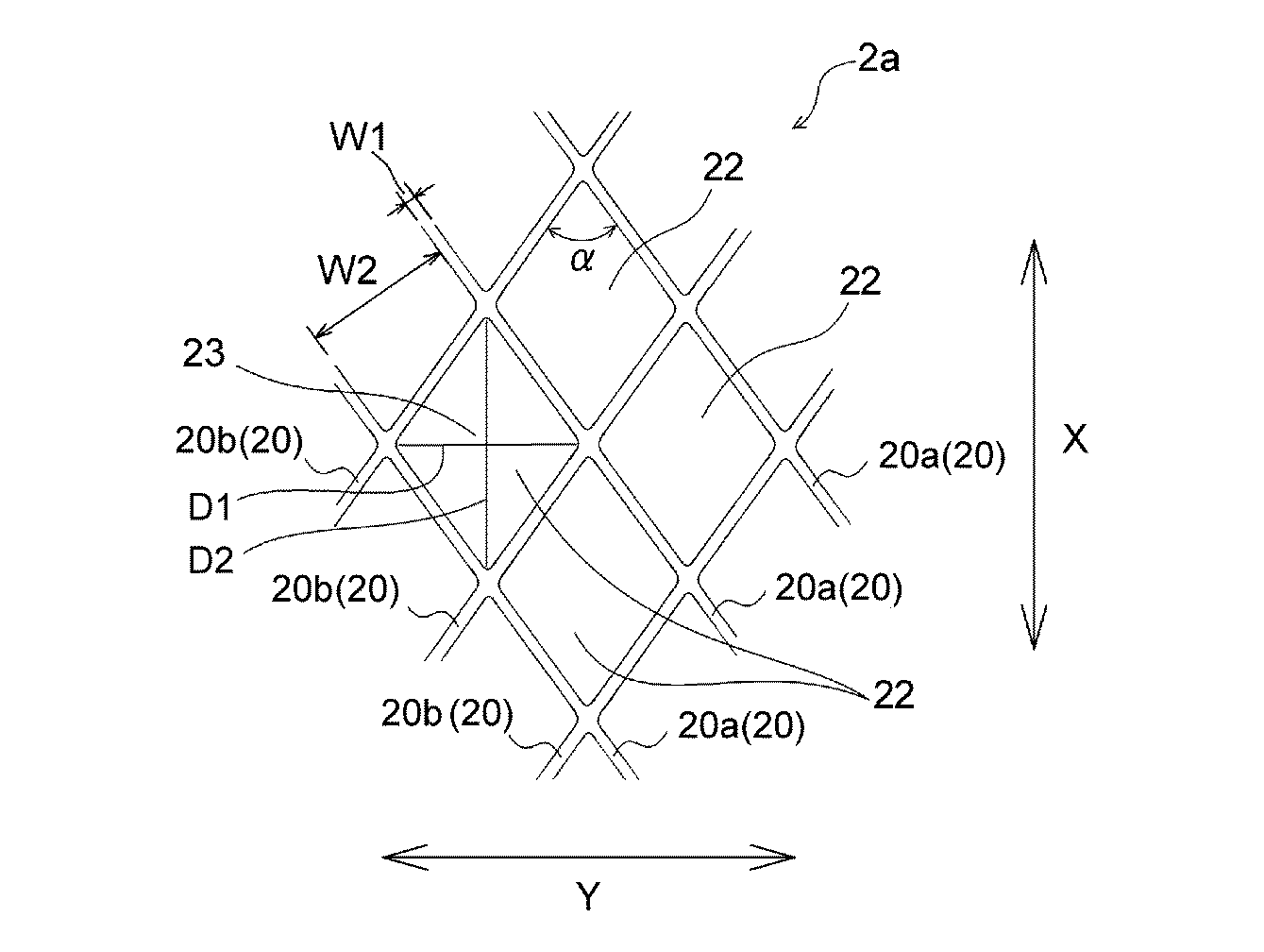
表2及び図10に示す結果から明らかなように、実施例1のナプキンは、注入量3gで下層吸収体側に擬似血液が到達したのに対し、比較例1及び2のナプキンはそれぞれ注入量5gで下層吸収体側に擬似血液が到達しており、実施例1のナプキンは、比較例1及び2のナプキンよりも、肌当接面側から非肌当接面側への液の伝達速度が速い。実施例1のナプキンの斯かる液の伝達速度の速さは、主として、表面シートとして、肌当接面側に物品幅方向に連続している線状の凹部が多数形成されている、物品幅方向に延びにくいシート(物品幅方向の10%伸長時の引張強度が150〜400cNの範囲にあるシート)を用いているためであると推測される。 As is apparent from the results shown in Table 2 and FIG. 10, the napkin of Example 1 reached the lower layer absorber side with an injection amount of 3 g, whereas the napkin of Comparative Examples 1 and 2 had an injection amount of 5 g. In the napkin of Example 1, the liquid transmission speed from the skin contact surface side to the non-skin contact surface side is faster than the napkin of Comparative Examples 1 and 2. . The speed of transmission of such a liquid of the napkin of Example 1 is mainly due to the article width in which a large number of linear concave portions continuous in the article width direction are formed on the skin contact surface side as the surface sheet. This is presumably because a sheet that does not easily extend in the direction (a sheet having a tensile strength in the range of 150 to 400 cN at 10% elongation in the article width direction) is used.
1 生理用ナプキン(吸収性物品)
2 表面シート
2P 表面シートの延出部
3 裏面シート
4 吸収体
8,8a,8b,8c,9,10 溝部
20 線状の凹部
22 区画領域
23 凸部
40 下層吸収体
41 前方中高部
42 後方中高部
A 前方部
B 後方部
H1 高密度部
H2 低密度部
1 Sanitary napkin (absorbent article)
2
Claims (4)
前記吸収体は、下層吸収体と、該下層吸収体よりも幅狭で且つ該下層吸収体の肌当接面側に配置された上層吸収体とを具備しており、
前記表面シートが、前記上層吸収体を物品幅方向に横断していると共に、該上層吸収体の物品長手方向に沿う両側縁から物品幅方向の外方に延出し、その延出部が、該両側縁よりも物品幅方向の外方において前記下層吸収体と共に圧密化されて、物品長手方向に延びる溝部が形成されており、
前記表面シートの肌当接面側に、該表面シートの構成繊維が圧着又は接着されて形成された線状の凹部が多数形成されており、該線状の凹部は少なくとも物品幅方向に連続しており、
前記上層吸収体は、その物品幅方向中央部が物品幅方向両側部よりも低密度である吸収性物品。 A vertically long absorbent article comprising a liquid-retaining absorbent, and a topsheet disposed on the skin contact surface side of the absorbent,
The absorber comprises a lower layer absorber and an upper layer absorber that is narrower than the lower layer absorber and disposed on the skin contact surface side of the lower layer absorber,
The top sheet crosses the upper absorbent body in the article width direction, and extends outward in the article width direction from both side edges along the article longitudinal direction of the upper absorbent body. It is consolidated with the lower layer absorber outside the article width direction from both side edges, and a groove portion extending in the article longitudinal direction is formed.
On the skin contact surface side of the surface sheet, a large number of linear recesses formed by crimping or bonding the constituent fibers of the surface sheet are formed, and the linear recesses are at least continuous in the article width direction. And
The upper layer absorbent body is an absorbent article in which the center part in the article width direction has a lower density than both side parts in the article width direction.
前記区画領域の中央部が、該区画領域を囲む前記線状の凹部に対して相対的に隆起して凸部となっている請求項2記載の吸収性物品。 The surface sheet includes a heat-extensible fiber whose length is extended by heating, and is formed by heat treatment after forming the linear recess in the web containing the heat-extensible fiber,
The absorbent article according to claim 2, wherein a central portion of the partition region is raised relative to the linear recess surrounding the partition region to form a protrusion.
Priority Applications (1)
| Application Number | Priority Date | Filing Date | Title |
|---|---|---|---|
| JP2009221990A JP2011067484A (en) | 2009-09-28 | 2009-09-28 | Absorbent article |
Applications Claiming Priority (1)
| Application Number | Priority Date | Filing Date | Title |
|---|---|---|---|
| JP2009221990A JP2011067484A (en) | 2009-09-28 | 2009-09-28 | Absorbent article |
Publications (1)
| Publication Number | Publication Date |
|---|---|
| JP2011067484A true JP2011067484A (en) | 2011-04-07 |
Family
ID=44013401
Family Applications (1)
| Application Number | Title | Priority Date | Filing Date |
|---|---|---|---|
| JP2009221990A Pending JP2011067484A (en) | 2009-09-28 | 2009-09-28 | Absorbent article |
Country Status (1)
| Country | Link |
|---|---|
| JP (1) | JP2011067484A (en) |
Cited By (61)
| Publication number | Priority date | Publication date | Assignee | Title |
|---|---|---|---|---|
| JP2012239722A (en) * | 2011-05-20 | 2012-12-10 | Kao Corp | Absorbent article |
| WO2013099739A1 (en) * | 2011-12-28 | 2013-07-04 | ユニ・チャーム株式会社 | Absorbent article and method of manufacturing same |
| WO2013146817A1 (en) * | 2012-03-30 | 2013-10-03 | ユニ・チャーム株式会社 | Absorbent article |
| WO2013145966A1 (en) * | 2012-03-30 | 2013-10-03 | ユニ・チャーム株式会社 | Absorbent article |
| WO2013146814A1 (en) * | 2012-03-30 | 2013-10-03 | ユニ・チャーム株式会社 | Absorptive article |
| JP2014515986A (en) * | 2011-06-13 | 2014-07-07 | ザ プロクター アンド ギャンブル カンパニー | Disposable absorbent article having a topsheet with a continuously joined pattern |
| JP2014210038A (en) * | 2013-04-18 | 2014-11-13 | 日本製紙クレシア株式会社 | Absorbent article |
| US8979815B2 (en) | 2012-12-10 | 2015-03-17 | The Procter & Gamble Company | Absorbent articles with channels |
| US9060904B2 (en) | 2007-06-18 | 2015-06-23 | The Procter & Gamble Company | Disposable absorbent article with sealed absorbent core with substantially continuously distributed absorbent particulate polymer material |
| US9066838B2 (en) | 2011-06-10 | 2015-06-30 | The Procter & Gamble Company | Disposable diaper having reduced absorbent core to backsheet gluing |
| US9072634B2 (en) | 2007-06-18 | 2015-07-07 | The Procter & Gamble Company | Disposable absorbent article with substantially continuously distributed absorbent particulate polymer material and method |
| US9216116B2 (en) | 2012-12-10 | 2015-12-22 | The Procter & Gamble Company | Absorbent articles with channels |
| US9216118B2 (en) | 2012-12-10 | 2015-12-22 | The Procter & Gamble Company | Absorbent articles with channels and/or pockets |
| US9301885B2 (en) | 2011-04-28 | 2016-04-05 | Unicharm Corporation | Absorbent article |
| WO2016060034A1 (en) * | 2014-10-17 | 2016-04-21 | ユニ・チャーム株式会社 | Absorbent article |
| US9326896B2 (en) | 2008-04-29 | 2016-05-03 | The Procter & Gamble Company | Process for making an absorbent core with strain resistant core cover |
| US9340363B2 (en) | 2009-12-02 | 2016-05-17 | The Procter & Gamble Company | Apparatus and method for transferring particulate material |
| US9339423B2 (en) | 2012-04-02 | 2016-05-17 | Unicharm Corporation | Absorbent article |
| US9351887B2 (en) | 2012-04-02 | 2016-05-31 | Unicharm Corporation | Absorbent article |
| US9375358B2 (en) | 2012-12-10 | 2016-06-28 | The Procter & Gamble Company | Absorbent article with high absorbent material content |
| US9375365B2 (en) | 2012-02-29 | 2016-06-28 | Unicharm Corporation | Absorbent article |
| US9375356B2 (en) | 2012-04-02 | 2016-06-28 | Unicharm Corporation | Absorbent article |
| US9381268B2 (en) | 2012-04-02 | 2016-07-05 | Unicharm Corporation | Absorbent article |
| US9387135B2 (en) | 2012-02-29 | 2016-07-12 | Unicharm Corporation | Absorbent article |
| US9468566B2 (en) | 2011-06-10 | 2016-10-18 | The Procter & Gamble Company | Absorbent structure for absorbent articles |
| US9492328B2 (en) | 2011-06-10 | 2016-11-15 | The Procter & Gamble Company | Method and apparatus for making absorbent structures with absorbent material |
| US9498387B2 (en) | 2012-02-29 | 2016-11-22 | Unicharm Corporation | Absorbent article having bent sections |
| US9532910B2 (en) | 2012-11-13 | 2017-01-03 | The Procter & Gamble Company | Absorbent articles with channels and signals |
| US9668926B2 (en) | 2011-06-10 | 2017-06-06 | The Procter & Gamble Company | Method and apparatus for making absorbent structures with absorbent material |
| US9713557B2 (en) | 2012-12-10 | 2017-07-25 | The Procter & Gamble Company | Absorbent article with high absorbent material content |
| US9713556B2 (en) | 2012-12-10 | 2017-07-25 | The Procter & Gamble Company | Absorbent core with high superabsorbent material content |
| US9763835B2 (en) | 2003-02-12 | 2017-09-19 | The Procter & Gamble Company | Comfortable diaper |
| US9770526B2 (en) | 2011-09-30 | 2017-09-26 | Unicharm Corporation | Absorbent article |
| US9775751B2 (en) | 2012-02-29 | 2017-10-03 | Unicharm Corporation | Absorbent article |
| US9789009B2 (en) | 2013-12-19 | 2017-10-17 | The Procter & Gamble Company | Absorbent articles having channel-forming areas and wetness indicator |
| US9789011B2 (en) | 2013-08-27 | 2017-10-17 | The Procter & Gamble Company | Absorbent articles with channels |
| US9974699B2 (en) | 2011-06-10 | 2018-05-22 | The Procter & Gamble Company | Absorbent core for disposable absorbent articles |
| US9987176B2 (en) | 2013-08-27 | 2018-06-05 | The Procter & Gamble Company | Absorbent articles with channels |
| JP2018102639A (en) * | 2016-12-27 | 2018-07-05 | 花王株式会社 | Absorbent article |
| US10071002B2 (en) | 2013-06-14 | 2018-09-11 | The Procter & Gamble Company | Absorbent article and absorbent core forming channels when wet |
| US10130527B2 (en) | 2013-09-19 | 2018-11-20 | The Procter & Gamble Company | Absorbent cores having material free areas |
| US10137039B2 (en) | 2013-12-19 | 2018-11-27 | The Procter & Gamble Company | Absorbent cores having channel-forming areas and C-wrap seals |
| US10149788B2 (en) | 2011-06-10 | 2018-12-11 | The Procter & Gamble Company | Disposable diapers |
| US10292875B2 (en) | 2013-09-16 | 2019-05-21 | The Procter & Gamble Company | Absorbent articles with channels and signals |
| US10322040B2 (en) | 2015-03-16 | 2019-06-18 | The Procter & Gamble Company | Absorbent articles with improved cores |
| US10322037B2 (en) | 2012-02-29 | 2019-06-18 | Unicharm Corporation | Absorbent article |
| US10470948B2 (en) | 2003-02-12 | 2019-11-12 | The Procter & Gamble Company | Thin and dry diaper |
| JP2019205781A (en) * | 2018-05-30 | 2019-12-05 | 花王株式会社 | Pad-shaped absorbent article |
| US10507144B2 (en) | 2015-03-16 | 2019-12-17 | The Procter & Gamble Company | Absorbent articles with improved strength |
| US10543129B2 (en) | 2015-05-29 | 2020-01-28 | The Procter & Gamble Company | Absorbent articles having channels and wetness indicator |
| US10543132B2 (en) | 2011-03-31 | 2020-01-28 | Unicharm Corporation | Absorbent article with blood modifying agent |
| US10561546B2 (en) | 2011-06-10 | 2020-02-18 | The Procter & Gamble Company | Absorbent structure for absorbent articles |
| US10632029B2 (en) | 2015-11-16 | 2020-04-28 | The Procter & Gamble Company | Absorbent cores having material free areas |
| US10639215B2 (en) | 2012-12-10 | 2020-05-05 | The Procter & Gamble Company | Absorbent articles with channels and/or pockets |
| US10736795B2 (en) | 2015-05-12 | 2020-08-11 | The Procter & Gamble Company | Absorbent article with improved core-to-backsheet adhesive |
| CN111526848A (en) * | 2017-12-28 | 2020-08-11 | 花王株式会社 | absorbent articles |
| US10842690B2 (en) | 2016-04-29 | 2020-11-24 | The Procter & Gamble Company | Absorbent core with profiled distribution of absorbent material |
| US11090199B2 (en) | 2014-02-11 | 2021-08-17 | The Procter & Gamble Company | Method and apparatus for making an absorbent structure comprising channels |
| US11123240B2 (en) | 2016-04-29 | 2021-09-21 | The Procter & Gamble Company | Absorbent core with transversal folding lines |
| US11207220B2 (en) | 2013-09-16 | 2021-12-28 | The Procter & Gamble Company | Absorbent articles with channels and signals |
| US11510829B2 (en) | 2014-05-27 | 2022-11-29 | The Procter & Gamble Company | Absorbent core with absorbent material pattern |
Citations (3)
| Publication number | Priority date | Publication date | Assignee | Title |
|---|---|---|---|---|
| JP2004141619A (en) * | 2002-06-14 | 2004-05-20 | Uni Charm Corp | Absorptive article |
| JP2006239162A (en) * | 2005-03-03 | 2006-09-14 | Kao Corp | Absorbent articles |
| JP2007215913A (en) * | 2006-02-20 | 2007-08-30 | Kao Corp | Absorbent articles |
-
2009
- 2009-09-28 JP JP2009221990A patent/JP2011067484A/en active Pending
Patent Citations (3)
| Publication number | Priority date | Publication date | Assignee | Title |
|---|---|---|---|---|
| JP2004141619A (en) * | 2002-06-14 | 2004-05-20 | Uni Charm Corp | Absorptive article |
| JP2006239162A (en) * | 2005-03-03 | 2006-09-14 | Kao Corp | Absorbent articles |
| JP2007215913A (en) * | 2006-02-20 | 2007-08-30 | Kao Corp | Absorbent articles |
Cited By (119)
| Publication number | Priority date | Publication date | Assignee | Title |
|---|---|---|---|---|
| US9763835B2 (en) | 2003-02-12 | 2017-09-19 | The Procter & Gamble Company | Comfortable diaper |
| US11793682B2 (en) | 2003-02-12 | 2023-10-24 | The Procter & Gamble Company | Thin and dry diaper |
| US11234868B2 (en) | 2003-02-12 | 2022-02-01 | The Procter & Gamble Company | Comfortable diaper |
| US10470948B2 (en) | 2003-02-12 | 2019-11-12 | The Procter & Gamble Company | Thin and dry diaper |
| US11135096B2 (en) | 2003-02-12 | 2021-10-05 | The Procter & Gamble Company | Comfortable diaper |
| US10660800B2 (en) | 2003-02-12 | 2020-05-26 | The Procter & Gamble Company | Comfortable diaper |
| US9241845B2 (en) | 2007-06-18 | 2016-01-26 | The Procter & Gamble Company | Disposable absorbent article with sealed absorbent core with substantially continuously distributed absorbent particulate polymer material |
| US9072634B2 (en) | 2007-06-18 | 2015-07-07 | The Procter & Gamble Company | Disposable absorbent article with substantially continuously distributed absorbent particulate polymer material and method |
| US9060904B2 (en) | 2007-06-18 | 2015-06-23 | The Procter & Gamble Company | Disposable absorbent article with sealed absorbent core with substantially continuously distributed absorbent particulate polymer material |
| US9326896B2 (en) | 2008-04-29 | 2016-05-03 | The Procter & Gamble Company | Process for making an absorbent core with strain resistant core cover |
| US9340363B2 (en) | 2009-12-02 | 2016-05-17 | The Procter & Gamble Company | Apparatus and method for transferring particulate material |
| US10004647B2 (en) | 2009-12-02 | 2018-06-26 | The Procter & Gamble Company | Apparatus and method for transferring particulate material |
| US10543132B2 (en) | 2011-03-31 | 2020-01-28 | Unicharm Corporation | Absorbent article with blood modifying agent |
| US9301885B2 (en) | 2011-04-28 | 2016-04-05 | Unicharm Corporation | Absorbent article |
| JP2012239722A (en) * | 2011-05-20 | 2012-12-10 | Kao Corp | Absorbent article |
| US9173784B2 (en) | 2011-06-10 | 2015-11-03 | The Procter & Gamble Company | Disposable diaper having reduced absorbent core to backsheet gluing |
| US11602467B2 (en) | 2011-06-10 | 2023-03-14 | The Procter & Gamble Company | Absorbent structure for absorbent articles |
| US10813794B2 (en) | 2011-06-10 | 2020-10-27 | The Procter & Gamble Company | Method and apparatus for making absorbent structures with absorbent material |
| US9649232B2 (en) | 2011-06-10 | 2017-05-16 | The Procter & Gamble Company | Disposable diaper having reduced absorbent core to backsheet gluing |
| US10893987B2 (en) | 2011-06-10 | 2021-01-19 | The Procter & Gamble Company | Disposable diapers with main channels and secondary channels |
| US9492328B2 (en) | 2011-06-10 | 2016-11-15 | The Procter & Gamble Company | Method and apparatus for making absorbent structures with absorbent material |
| US11000422B2 (en) | 2011-06-10 | 2021-05-11 | The Procter & Gamble Company | Method and apparatus for making absorbent structures with absorbent material |
| US10561546B2 (en) | 2011-06-10 | 2020-02-18 | The Procter & Gamble Company | Absorbent structure for absorbent articles |
| US11110011B2 (en) | 2011-06-10 | 2021-09-07 | The Procter & Gamble Company | Absorbent structure for absorbent articles |
| US9468566B2 (en) | 2011-06-10 | 2016-10-18 | The Procter & Gamble Company | Absorbent structure for absorbent articles |
| US9668926B2 (en) | 2011-06-10 | 2017-06-06 | The Procter & Gamble Company | Method and apparatus for making absorbent structures with absorbent material |
| US10517777B2 (en) | 2011-06-10 | 2019-12-31 | The Procter & Gamble Company | Disposable diaper having first and second absorbent structures and channels |
| US11135105B2 (en) | 2011-06-10 | 2021-10-05 | The Procter & Gamble Company | Absorbent structure for absorbent articles |
| US9066838B2 (en) | 2011-06-10 | 2015-06-30 | The Procter & Gamble Company | Disposable diaper having reduced absorbent core to backsheet gluing |
| US9974699B2 (en) | 2011-06-10 | 2018-05-22 | The Procter & Gamble Company | Absorbent core for disposable absorbent articles |
| US11911250B2 (en) | 2011-06-10 | 2024-02-27 | The Procter & Gamble Company | Absorbent structure for absorbent articles |
| US10245188B2 (en) | 2011-06-10 | 2019-04-02 | The Procter & Gamble Company | Method and apparatus for making absorbent structures with absorbent material |
| US10149788B2 (en) | 2011-06-10 | 2018-12-11 | The Procter & Gamble Company | Disposable diapers |
| US10130525B2 (en) | 2011-06-10 | 2018-11-20 | The Procter & Gamble Company | Absorbent structure for absorbent articles |
| JP2014515986A (en) * | 2011-06-13 | 2014-07-07 | ザ プロクター アンド ギャンブル カンパニー | Disposable absorbent article having a topsheet with a continuously joined pattern |
| US9770526B2 (en) | 2011-09-30 | 2017-09-26 | Unicharm Corporation | Absorbent article |
| JP2013150779A (en) * | 2011-12-28 | 2013-08-08 | Unicharm Corp | Absorbent article and method of manufacturing the same |
| US10278873B2 (en) | 2011-12-28 | 2019-05-07 | Unicharm Corporation | Absorbent article having a domed section and method of manufacturing same |
| WO2013099739A1 (en) * | 2011-12-28 | 2013-07-04 | ユニ・チャーム株式会社 | Absorbent article and method of manufacturing same |
| CN104023682A (en) * | 2011-12-28 | 2014-09-03 | 尤妮佳股份有限公司 | Absorbent article and method of manufacturing same |
| TWI572339B (en) * | 2011-12-28 | 2017-03-01 | 優你 嬌美股份有限公司 | Absorbent article and method of manufacturing same |
| EP2799048A4 (en) * | 2011-12-28 | 2015-08-26 | Unicharm Corp | Absorbent article and method of manufacturing same |
| US10772770B2 (en) | 2012-02-29 | 2020-09-15 | Unicharm Corporation | Absorbent article |
| US9775751B2 (en) | 2012-02-29 | 2017-10-03 | Unicharm Corporation | Absorbent article |
| US9498387B2 (en) | 2012-02-29 | 2016-11-22 | Unicharm Corporation | Absorbent article having bent sections |
| US10322037B2 (en) | 2012-02-29 | 2019-06-18 | Unicharm Corporation | Absorbent article |
| US9387135B2 (en) | 2012-02-29 | 2016-07-12 | Unicharm Corporation | Absorbent article |
| US9375365B2 (en) | 2012-02-29 | 2016-06-28 | Unicharm Corporation | Absorbent article |
| JP2013208384A (en) * | 2012-03-30 | 2013-10-10 | Unicharm Corp | Absorbent article |
| CN104334134A (en) * | 2012-03-30 | 2015-02-04 | 尤妮佳股份有限公司 | Absorbent article |
| WO2013146817A1 (en) * | 2012-03-30 | 2013-10-03 | ユニ・チャーム株式会社 | Absorbent article |
| AU2013241415B2 (en) * | 2012-03-30 | 2017-05-18 | Unicharm Corporation | Absorbent article |
| CN104244883A (en) * | 2012-03-30 | 2014-12-24 | 尤妮佳股份有限公司 | Absorptive article |
| EP2832331A4 (en) * | 2012-03-30 | 2015-08-26 | Unicharm Corp | Absorptive article |
| JP2013208361A (en) * | 2012-03-30 | 2013-10-10 | Unicharm Corp | Absorbent article |
| AU2013241412B2 (en) * | 2012-03-30 | 2017-06-29 | Unicharm Corporation | Absorptive article |
| JP2013208280A (en) * | 2012-03-30 | 2013-10-10 | Unicharm Corp | Absorbent article |
| WO2013146814A1 (en) * | 2012-03-30 | 2013-10-03 | ユニ・チャーム株式会社 | Absorptive article |
| US9233185B2 (en) | 2012-03-30 | 2016-01-12 | Unicharm Corporation | Absorbent article |
| WO2013145966A1 (en) * | 2012-03-30 | 2013-10-03 | ユニ・チャーム株式会社 | Absorbent article |
| US9314383B2 (en) | 2012-03-30 | 2016-04-19 | Unicharm Corporation | Absorptive article |
| CN104244883B (en) * | 2012-03-30 | 2016-06-22 | 尤妮佳股份有限公司 | absorbent article |
| US9339423B2 (en) | 2012-04-02 | 2016-05-17 | Unicharm Corporation | Absorbent article |
| US9351887B2 (en) | 2012-04-02 | 2016-05-31 | Unicharm Corporation | Absorbent article |
| US9375356B2 (en) | 2012-04-02 | 2016-06-28 | Unicharm Corporation | Absorbent article |
| US9381268B2 (en) | 2012-04-02 | 2016-07-05 | Unicharm Corporation | Absorbent article |
| US9532910B2 (en) | 2012-11-13 | 2017-01-03 | The Procter & Gamble Company | Absorbent articles with channels and signals |
| US10449097B2 (en) | 2012-11-13 | 2019-10-22 | The Procter & Gamble Company | Absorbent articles with channels and signals |
| US10022280B2 (en) | 2012-12-10 | 2018-07-17 | The Procter & Gamble Company | Absorbent article with high absorbent material content |
| US10639215B2 (en) | 2012-12-10 | 2020-05-05 | The Procter & Gamble Company | Absorbent articles with channels and/or pockets |
| US9713556B2 (en) | 2012-12-10 | 2017-07-25 | The Procter & Gamble Company | Absorbent core with high superabsorbent material content |
| US9713557B2 (en) | 2012-12-10 | 2017-07-25 | The Procter & Gamble Company | Absorbent article with high absorbent material content |
| US8979815B2 (en) | 2012-12-10 | 2015-03-17 | The Procter & Gamble Company | Absorbent articles with channels |
| US12274609B2 (en) | 2012-12-10 | 2025-04-15 | The Procter & Gamble Company | Absorbent article with high absorbent material content |
| US9216116B2 (en) | 2012-12-10 | 2015-12-22 | The Procter & Gamble Company | Absorbent articles with channels |
| US12016761B2 (en) | 2012-12-10 | 2024-06-25 | The Procter & Gamble Company | Absorbent article with high absorbent material content |
| US9216118B2 (en) | 2012-12-10 | 2015-12-22 | The Procter & Gamble Company | Absorbent articles with channels and/or pockets |
| US9375358B2 (en) | 2012-12-10 | 2016-06-28 | The Procter & Gamble Company | Absorbent article with high absorbent material content |
| JP2014210038A (en) * | 2013-04-18 | 2014-11-13 | 日本製紙クレシア株式会社 | Absorbent article |
| US10071002B2 (en) | 2013-06-14 | 2018-09-11 | The Procter & Gamble Company | Absorbent article and absorbent core forming channels when wet |
| US9987176B2 (en) | 2013-08-27 | 2018-06-05 | The Procter & Gamble Company | Absorbent articles with channels |
| US11406544B2 (en) | 2013-08-27 | 2022-08-09 | The Procter & Gamble Company | Absorbent articles with channels |
| US10736794B2 (en) | 2013-08-27 | 2020-08-11 | The Procter & Gamble Company | Absorbent articles with channels |
| US10335324B2 (en) | 2013-08-27 | 2019-07-02 | The Procter & Gamble Company | Absorbent articles with channels |
| US9789011B2 (en) | 2013-08-27 | 2017-10-17 | The Procter & Gamble Company | Absorbent articles with channels |
| US10765567B2 (en) | 2013-08-27 | 2020-09-08 | The Procter & Gamble Company | Absorbent articles with channels |
| US11612523B2 (en) | 2013-08-27 | 2023-03-28 | The Procter & Gamble Company | Absorbent articles with channels |
| US11759376B2 (en) | 2013-08-27 | 2023-09-19 | The Procter & Gamble Company | Absorbent articles with channels |
| US11207220B2 (en) | 2013-09-16 | 2021-12-28 | The Procter & Gamble Company | Absorbent articles with channels and signals |
| US11957551B2 (en) | 2013-09-16 | 2024-04-16 | The Procter & Gamble Company | Absorbent articles with channels and signals |
| US10292875B2 (en) | 2013-09-16 | 2019-05-21 | The Procter & Gamble Company | Absorbent articles with channels and signals |
| US10130527B2 (en) | 2013-09-19 | 2018-11-20 | The Procter & Gamble Company | Absorbent cores having material free areas |
| US11154437B2 (en) | 2013-09-19 | 2021-10-26 | The Procter & Gamble Company | Absorbent cores having material free areas |
| US11944526B2 (en) | 2013-09-19 | 2024-04-02 | The Procter & Gamble Company | Absorbent cores having material free areas |
| US10828206B2 (en) | 2013-12-19 | 2020-11-10 | Procter & Gamble Company | Absorbent articles having channel-forming areas and wetness indicator |
| US9789009B2 (en) | 2013-12-19 | 2017-10-17 | The Procter & Gamble Company | Absorbent articles having channel-forming areas and wetness indicator |
| US12226292B2 (en) | 2013-12-19 | 2025-02-18 | The Procter & Gamble Company | Absorbent articles having channel-forming areas and wetness indicator |
| US10137039B2 (en) | 2013-12-19 | 2018-11-27 | The Procter & Gamble Company | Absorbent cores having channel-forming areas and C-wrap seals |
| US11191679B2 (en) | 2013-12-19 | 2021-12-07 | The Procter & Gamble Company | Absorbent articles having channel-forming areas and wetness indicator |
| US10675187B2 (en) | 2013-12-19 | 2020-06-09 | The Procter & Gamble Company | Absorbent articles having channel-forming areas and wetness indicator |
| US11090199B2 (en) | 2014-02-11 | 2021-08-17 | The Procter & Gamble Company | Method and apparatus for making an absorbent structure comprising channels |
| US11510829B2 (en) | 2014-05-27 | 2022-11-29 | The Procter & Gamble Company | Absorbent core with absorbent material pattern |
| JP2016077581A (en) * | 2014-10-17 | 2016-05-16 | ユニ・チャーム株式会社 | Absorbent article |
| WO2016060034A1 (en) * | 2014-10-17 | 2016-04-21 | ユニ・チャーム株式会社 | Absorbent article |
| US10322040B2 (en) | 2015-03-16 | 2019-06-18 | The Procter & Gamble Company | Absorbent articles with improved cores |
| US10507144B2 (en) | 2015-03-16 | 2019-12-17 | The Procter & Gamble Company | Absorbent articles with improved strength |
| US10736795B2 (en) | 2015-05-12 | 2020-08-11 | The Procter & Gamble Company | Absorbent article with improved core-to-backsheet adhesive |
| US11918445B2 (en) | 2015-05-12 | 2024-03-05 | The Procter & Gamble Company | Absorbent article with improved core-to-backsheet adhesive |
| US11497657B2 (en) | 2015-05-29 | 2022-11-15 | The Procter & Gamble Company | Absorbent articles having channels and wetness indicator |
| US10543129B2 (en) | 2015-05-29 | 2020-01-28 | The Procter & Gamble Company | Absorbent articles having channels and wetness indicator |
| US10632029B2 (en) | 2015-11-16 | 2020-04-28 | The Procter & Gamble Company | Absorbent cores having material free areas |
| US10842690B2 (en) | 2016-04-29 | 2020-11-24 | The Procter & Gamble Company | Absorbent core with profiled distribution of absorbent material |
| US11123240B2 (en) | 2016-04-29 | 2021-09-21 | The Procter & Gamble Company | Absorbent core with transversal folding lines |
| US12472111B2 (en) | 2016-04-29 | 2025-11-18 | The Procter & Gamble Company | Absorbent core with profiled distribution of absorbent material |
| JP2018102639A (en) * | 2016-12-27 | 2018-07-05 | 花王株式会社 | Absorbent article |
| CN111526848B (en) * | 2017-12-28 | 2022-01-07 | 花王株式会社 | Absorbent article |
| CN111526848A (en) * | 2017-12-28 | 2020-08-11 | 花王株式会社 | absorbent articles |
| JP7099877B2 (en) | 2018-05-30 | 2022-07-12 | 花王株式会社 | Pad-shaped absorbent article |
| JP2019205781A (en) * | 2018-05-30 | 2019-12-05 | 花王株式会社 | Pad-shaped absorbent article |
Similar Documents
| Publication | Publication Date | Title |
|---|---|---|
| JP2011067484A (en) | Absorbent article | |
| JP5374345B2 (en) | Sanitary napkin | |
| JP5411663B2 (en) | Absorbent articles | |
| JP6158992B2 (en) | Absorbent articles | |
| CN105073078B (en) | absorbent articles | |
| TWI620552B (en) | Absorbent article and method of manufacturing same | |
| KR102003079B1 (en) | Absorbent article | |
| JP5318747B2 (en) | Absorbent articles | |
| US20030187417A1 (en) | Absorbent article and manufacturing method thereof | |
| KR101605583B1 (en) | Absorbent article and manufacturing apparatus for absorbent article | |
| JP5268662B2 (en) | Absorbent article surface sheet | |
| JP2017038925A5 (en) | ||
| CN102762178B (en) | Absorbent structure for bodily fluid-absorbent wearing article | |
| JP2010148730A (en) | Surface sheet of absorbent article | |
| CN102834080A (en) | Absorbent article | |
| JP6580171B2 (en) | Absorber, method for producing the same, and absorbent article | |
| WO2017030136A1 (en) | Absorbent article | |
| JP2015089395A (en) | Absorber, absorbent article, and manufacturing method thereof | |
| JP5600539B2 (en) | Absorbent articles | |
| JP2012090689A (en) | Absorbent article | |
| JP2011255116A (en) | Absorptive article | |
| JP2021065433A (en) | Absorbent article | |
| JP5688265B2 (en) | Absorbent articles | |
| JP2017086621A (en) | Absorbent product | |
| WO2016136943A1 (en) | Absorbent article |
Legal Events
| Date | Code | Title | Description |
|---|---|---|---|
| A621 | Written request for application examination |
Free format text: JAPANESE INTERMEDIATE CODE: A621 Effective date: 20120607 |
|
| A977 | Report on retrieval |
Free format text: JAPANESE INTERMEDIATE CODE: A971007 Effective date: 20130416 |
|
| A131 | Notification of reasons for refusal |
Free format text: JAPANESE INTERMEDIATE CODE: A131 Effective date: 20130423 |
|
| A521 | Written amendment |
Free format text: JAPANESE INTERMEDIATE CODE: A523 Effective date: 20130612 |
|
| A02 | Decision of refusal |
Free format text: JAPANESE INTERMEDIATE CODE: A02 Effective date: 20131001 |