以下、本発明の実施の形態を添付図面に従って説明する。最初に画像形成装置の全体的構成について説明し、その後、各部の特徴的な構成について説明する。
Hereinafter, embodiments of the present invention will be described with reference to the accompanying drawings. First, the overall configuration of the image forming apparatus will be described, and then the characteristic configuration of each unit will be described.
図1,図2は、本発明に係る画像形成装置の一形態であるカラー複写機を示す概略図である。このカラー複写機は、中央に画像形成装置本体となる複写機本体100、その下部にテーブル状に構成された給紙部200が配置され、複写機本体100の上方にスキャナ300、スキャナ300の上方に原稿自動搬送装置400を配置した構成となっている。給紙部200は複写機本体100と連結されていて大きくは複写機本体100の一部を構成している。なお、給紙部200はテーブル状の構成ではなく、複写機本体100内に収納された形態のものであってもよい。
1 and 2 are schematic views showing a color copying machine which is an embodiment of an image forming apparatus according to the present invention. In this color copying machine, a copying machine main body 100 serving as an image forming apparatus main body is disposed at the center, and a sheet feeding unit 200 configured in a table shape is disposed below the copying machine main body 100. The automatic document feeder 400 is arranged in the front. The paper feeding unit 200 is connected to the copying machine main body 100 and largely constitutes a part of the copying machine main body 100. Note that the sheet feeding unit 200 may have a form stored in the copying machine main body 100 instead of a table-like configuration.
本形態における複写機本体100の一部となる給紙部200には、媒体収納容器となるトナー容器70を収納するためのトレイ1が配設されている。トレイ1の配置形態としては、給紙部200ではなく、複写機本体100に配設しても無論構わない。トレイ関連の構成については、後述する。
A tray 1 for storing a toner container 70 serving as a medium storage container is disposed in a paper feeding unit 200 that is a part of the copying machine main body 100 in this embodiment. Of course, the tray 1 may be arranged not in the paper feeding unit 200 but in the copying machine main body 100. The tray-related configuration will be described later.
複写機本体100には、図2に示すように、複数のローラ14、15、16に巻き掛けられた可撓性を有する無端ベルトにより構成された像担持体としての中間転写ベルト19が設けられている。この中間転写ベルト19は、複数のローラ14,15,16のうち1つのローラが図示していない駆動装置によって回転駆動され、これにより中間転写ベルト19が矢印で示す時計方向に走行駆動され、他のローラが従動回転する。このように走行する中間転写ベルト19の上部走行辺には、ブラック、シアン、マゼンタ、イエローの作像ユニット18が横に並べるようにしてそれぞれ配置されている。すなわち、ローラ14とローラ15間の走行辺上に、異なる色の4つの作像ユニット18を配置してタンデム画像形成部20を構成している。
As shown in FIG. 2, the copying machine main body 100 is provided with an intermediate transfer belt 19 as an image carrier composed of a flexible endless belt wound around a plurality of rollers 14, 15, 16. ing. In the intermediate transfer belt 19, one of the plurality of rollers 14, 15, and 16 is rotationally driven by a driving device (not shown), whereby the intermediate transfer belt 19 is driven to run in the clockwise direction indicated by an arrow. The roller rotates. Black, cyan, magenta, and yellow image forming units 18 are arranged side by side on the upper traveling side of the intermediate transfer belt 19 that travels in this manner. That is, the tandem image forming unit 20 is configured by arranging four image forming units 18 of different colors on the running side between the roller 14 and the roller 15.
4つの作像ユニット18は、中間転写ベルト19に接する潜像担持体としての感光体ドラム40をそれぞれ具備している。これら感光体ドラム40の周りには、帯電装置、現像装置58、クリーニング装置、除電装置等が配置され、さらに感光体ドラム40が中間転写ベルト19に接する位置における中間転写ベルト19の内側には転写装置57が設けられている。本実施形態の場合、4つの作像ユニット18は同一構造に構成されているが、現像装置58に収納されている画像形成媒体となるトナーの色がイエロー、マゼンタ、シアン、ブラックの4色に分けられている。また、各作像ユニット18の上方には光変調されたレーザ光を各感光体ドラムの表面に照射する露光装置21が配置され、このレーザ光は帯電装置と現像装置58の間で感光体ドラムにそれぞれ照射する。露光装置21は、各作像ユニット18に設けてもよいが、共通の露光装置21を用いればコストの点で有利である。
Each of the four image forming units 18 includes a photosensitive drum 40 as a latent image carrier in contact with the intermediate transfer belt 19. Around these photosensitive drums 40, a charging device, a developing device 58, a cleaning device, a static eliminator, and the like are arranged. Further, a transfer is performed inside the intermediate transfer belt 19 at a position where the photosensitive drum 40 contacts the intermediate transfer belt 19. A device 57 is provided. In the case of this embodiment, the four image forming units 18 have the same structure, but the color of the toner serving as the image forming medium housed in the developing device 58 is four colors of yellow, magenta, cyan, and black. It is divided. Further, an exposure device 21 for irradiating the surface of each photosensitive drum with light-modulated laser light is disposed above each image forming unit 18, and this laser light is provided between the charging device and the developing device 58. Irradiate each. Although the exposure apparatus 21 may be provided in each image forming unit 18, using the common exposure apparatus 21 is advantageous in terms of cost.
一方、中間転写ベルト19を挟んでタンデム画像形成部20と反対の側には、2次転写装置22が設けられている。2次転写装置22は、複数のローラ23間に、無端ベルトである2次転写ベルト24を巻き掛け、該ベルトが中間転写ベルト19を介してローラ16に押し当てられるように配置されている。なお、図1において、2次転写装置22の左横には、シート上に担持された転写画像(トナー画像)を定着するための定着装置25が設けられている。
On the other hand, a secondary transfer device 22 is provided on the opposite side of the intermediate transfer belt 19 from the tandem image forming unit 20. The secondary transfer device 22 is arranged so that a secondary transfer belt 24, which is an endless belt, is wound around a plurality of rollers 23, and the belt is pressed against the rollers 16 via the intermediate transfer belt 19. In FIG. 1, a fixing device 25 for fixing a transfer image (toner image) carried on a sheet is provided on the left side of the secondary transfer device 22.
2次転写装置22には、画像転写後のシートをこの定着装置25へと搬送するシート搬送機能も備えてなる。無論、2次転写装置22として、非接触のチャージャを配置してもよく、そのような場合は、転写後のシートを定着装置25まで搬送するシート搬送装置を、別途設ける必要が生ずる。なお、図示の例では、このような2次転写装置22及び定着装置25の下に、上述したタンデム画像形成部20と平行に、シートの両面に画像を記録すべくシートを反転するシート反転装置28を備えている。
The secondary transfer device 22 is also provided with a sheet transport function for transporting the image-transferred sheet to the fixing device 25. Of course, a non-contact charger may be arranged as the secondary transfer device 22. In such a case, it is necessary to separately provide a sheet conveying device for conveying the transferred sheet to the fixing device 25. In the illustrated example, a sheet reversing device for reversing the sheet so as to record images on both sides of the sheet is provided below the secondary transfer device 22 and the fixing device 25 in parallel with the tandem image forming unit 20 described above. 28.
このような構成のカラー複写機を用いてコピーをとるときは、原稿自動搬送装置400の原稿台30上に原稿をセットする。または、原稿自動搬送装置400を開いてスキャナ300のコンタクトガラス32上に原稿をセットし、原稿自動搬送装置400を閉じてそれで押さえる。
When making a copy using the color copying machine having such a configuration, a document is set on the document table 30 of the automatic document feeder 400. Alternatively, the automatic document feeder 400 is opened, a document is set on the contact glass 32 of the scanner 300, and the automatic document feeder 400 is closed and pressed by it.
そして、図示していないスタートスイッチを押すと、原稿自動搬送装置400に原稿をセットしたときは、原稿を搬送してコンタクトガラス32上へと移動して後、他方コンタクトガラス32上に原稿をセットしたときは、直ちにスキャナ300を駆動し、第1走行体33及び第2走行体34を走行する。そして、第1走行体33で光源から光を発射するとともに原稿面からの反射光をさらに反射して第2走行体34に向け、第2走行体34のミラーで反射して結像レンズ35を通して読み取りセンサ36に入れ、原稿内容が読み取られる。
When a start switch (not shown) is pressed, when the document is set on the automatic document feeder 400, the document is transported and moved onto the contact glass 32, and then the document is set on the other contact glass 32. When this happens, the scanner 300 is immediately driven to travel on the first traveling body 33 and the second traveling body 34. Then, the first traveling body 33 emits light from the light source and further reflects the reflected light from the document surface toward the second traveling body 34, and is reflected by the mirror of the second traveling body 34 and passes through the imaging lens 35. The document is placed in the reading sensor 36 and the contents of the document are read.
また、上記スタートスイッチを押すことで中間転写ベルト19にも走行開始の命令がされ、回転走行を開始する。同時に、個々の作像ユニット18でその感光体40を回転して各感光体40上にそれぞれ、ブラック、イエロー、マゼンタ、シアンの単色画像を形成する。そして、中間転写ベルト19の走行とともに、それらの単色画像を順次ベルトへと転写して中間転写ベルト19上に合成カラー画像を形成する。一方、上記スタートスイッチを押すことで給紙部200にも動作開始の命令がされる。給紙部200の給紙ローラ42の1つを選択回転し、ペーパーバンク43に多段に備える給紙カセット44の1つからシートが繰り出され、分離ローラ45で1枚ずつ分離して給紙路46に入れ、搬送ローラ47で搬送して複写機本体100内の給紙路48に導かれ、レジストローラ49に突き当って停止する。または、手差し給紙を選択した場合には給紙ローラ50を回転して手差しトレイ51上のシートが繰り出され、分離ローラ52で1枚ずつ分離されて手差し給紙路53に入れ、同じくレジストローラ49に突き当って停止する。
In addition, when the start switch is pressed, the intermediate transfer belt 19 is also instructed to start running and starts rotating. At the same time, the photoreceptors 40 are rotated by the individual image forming units 18 to form black, yellow, magenta, and cyan single color images on the photoreceptors 40, respectively. As the intermediate transfer belt 19 travels, the monochrome images are sequentially transferred to the belt to form a composite color image on the intermediate transfer belt 19. On the other hand, when the start switch is pressed, the sheet feeding unit 200 is also instructed to start operation. One of the paper feed rollers 42 of the paper feed unit 200 is selectively rotated, and the sheet is fed out from one of the paper feed cassettes 44 provided in multiple stages in the paper bank 43, and is separated one by one by the separation roller 45. 46, transported by the transport roller 47, guided to the paper feed path 48 in the copying machine main body 100, hits the registration roller 49 and stops. Alternatively, when manual feed is selected, the sheet feed roller 50 is rotated to feed out the sheets on the manual feed tray 51, separated one by one by the separation roller 52, and put into the manual feed path 53. Stop at 49.
そして、中間転写ベルト19上の合成カラー画像にタイミングを合わせてレジストローラ49が回転し、中間転写ベルト19と2次転写装置22との間にシートが送り込まれ、2次転写装置22で転写してシート上に一括してフルカラー画像が記録される。画像転写後のシートは、2次転写装置22で搬送されて定着装置25へと送り込まれ、定着装置25で熱と圧力とを加えて転写画像を定着された後、切り換爪55でシート搬送路を切り換えて排出ローラ26によって排紙トレイ27上にスタックされる。または、切り換え爪55で切り換えてシート反転装置28に入いり、そこで反転して再び転写位置へと導かれ、裏面にも画像を記録された後、排出ローラ26で排紙トレイ27上に排出される。一方、画像転写後の中間転写ベルト19は、中間転写体クリーニング装置17で、画像転写後に中間転写ベルト19上に残留する残留トナーを除去され、タンデム画像形成部20による再度の画像形成に備える。
Then, the registration roller 49 rotates in synchronization with the composite color image on the intermediate transfer belt 19, and a sheet is fed between the intermediate transfer belt 19 and the secondary transfer device 22, and transferred by the secondary transfer device 22. A full color image is recorded on the sheet at once. The sheet after the image transfer is conveyed by the secondary transfer device 22 and sent to the fixing device 25. After fixing the transferred image by applying heat and pressure by the fixing device 25, the sheet is conveyed by the switching claw 55. The path is switched and stacked on the discharge tray 27 by the discharge roller 26. Alternatively, the sheet is switched by the switching claw 55 and enters the sheet reversing device 28, where it is reversed and guided to the transfer position again. After the image is recorded on the back surface, the sheet is discharged onto the sheet discharge tray 27 by the discharge roller 26. The On the other hand, the residual toner remaining on the intermediate transfer belt 19 after the image transfer is removed from the intermediate transfer belt 19 after the image transfer by the intermediate transfer body cleaning device 17 to prepare for the image formation by the tandem image forming unit 20 again.
図3は、本発明に係る媒体補給装置としてのトナー補給装置10の概略構成を示すものである。図3において、符号58は現像装置である。現像装置58はいわゆる2成分現像器であって、その内部にトナーとキャリアを混合した現像剤が貯蔵されている。かかる現像装置58では、画像の形成に伴って媒体となるトナーが消費されるため、その分のトナーを補給する必要がある。トナー補給制御には、種々の方法が提案されているが、一般的にはトナーとキャリアの混合比を検知することや、感光体ドラム1上に形成したパターン画像の濃度を検知し、その検知結果に基づいてトナー補給信号を出力するようにしている。
FIG. 3 shows a schematic configuration of a toner supply device 10 as a medium supply device according to the present invention. In FIG. 3, reference numeral 58 denotes a developing device. The developing device 58 is a so-called two-component developing device in which a developer mixed with toner and carrier is stored. In such a developing device 58, toner serving as a medium is consumed as the image is formed. Therefore, it is necessary to replenish that much toner. Various methods have been proposed for toner replenishment control. In general, the toner / carrier mixing ratio is detected, or the density of the pattern image formed on the photosensitive drum 1 is detected and detected. Based on the result, a toner replenishment signal is output.
現像装置58上には、トナー収納容器70内に収納されているトナーを吸引する吸引手段であり、媒体搬送ポンプの1つである一軸偏芯スクリューポンプ(以下、粉体ポンプ80という。)が設けられている。この粉体ポンプ80は、ゴム等の弾性部材で作られたダブルピッチの螺旋溝を形成した雌ねじ形ステータ82と、該ステータ82内に回動自在に嵌挿され、金属や樹脂等から作られた雄ねじ形ロータ81とを有している。このロータ81は、駆動軸84にスプリングピン等によって連結されており、駆動軸84が回転されることによって回転駆動される。ステータ82は、その周囲をケース85に固定されたホルダ83に覆われており、そのホルダ83の内周面とステータ82の外周面との間には隙間が設けられている。
On the developing device 58, a uniaxial eccentric screw pump (hereinafter referred to as a powder pump 80) which is a suction means for sucking the toner stored in the toner storage container 70 and is one of the medium transport pumps. Is provided. This powder pump 80 is made of a metal threaded stator 82 which is rotatably inserted into the stator 82 and has a female threaded stator 82 formed with a double pitch spiral groove made of an elastic member such as rubber. And an externally threaded rotor 81. The rotor 81 is connected to the drive shaft 84 by a spring pin or the like, and is driven to rotate when the drive shaft 84 is rotated. The periphery of the stator 82 is covered with a holder 83 fixed to the case 85, and a gap is provided between the inner peripheral surface of the holder 83 and the outer peripheral surface of the stator 82.
現像装置58に補給するトナーは、トナー収納容器70に収納され、粉体ポンプ80とトナー収納容器70とが補給経路を構成する管状部材としてのトナーチューブ86によって連通している。これら粉体ポンプ80とトナーチューブ86にわって媒体搬送装置300が構成されている。トナーチューブ86は、トレイ1の引き出し量以上の弛みを有しているパイプ状のものならば種類を問わないが、弾性変形可能な、すなわちフレキシブルなチューブで構成すれば、トナー収納容器70と現像装置58との配置関係の規制がなくなり、設計自由度が大幅に増す。なお、フレキシブルなチューブとしては、耐トナー性に優れたゴム材料、例えば、ポリウレタン、ニトリル、EPDM等を用いることが好適である。トナー収納容器70側に位置するトナーチューブ86の端部には、トナー収納容器70に設けられた媒体排出部となる口金部材71に結合される媒体受入部となるトナー吸引ノズル91が設けられている。
The toner to be supplied to the developing device 58 is stored in a toner storage container 70, and the powder pump 80 and the toner storage container 70 are communicated with each other by a toner tube 86 as a tubular member constituting a supply path. Instead of the powder pump 80 and the toner tube 86, a medium conveying device 300 is configured. The toner tube 86 may be of any type as long as it is a pipe having a slack that is greater than or equal to the amount that the tray 1 is pulled out. The restriction of the arrangement relationship with the device 58 is eliminated, and the degree of freedom in design is greatly increased. As the flexible tube, it is preferable to use a rubber material excellent in toner resistance, such as polyurethane, nitrile, EPDM or the like. A toner suction nozzle 91 serving as a medium receiving portion coupled to a base member 71 serving as a medium discharge portion provided in the toner storage container 70 is provided at an end portion of the toner tube 86 located on the toner storage container 70 side. Yes.
粉体ポンプ80の配置は、現像装置58に設ける形態に限定されるものではなく、トナーチューブ86の途中に配置されていればよいため、トナー吸引ノズル91側とトレイ1に配置する形態であってもよい。つまり、トナーチューブ86の途中とは、現像装置58やトレイ1も含まれる。
The arrangement of the powder pump 80 is not limited to the form provided in the developing device 58, and may be arranged in the middle of the toner tube 86. Therefore, the powder pump 80 is arranged in the toner suction nozzle 91 side and the tray 1. May be. That is, the middle of the toner tube 86 includes the developing device 58 and the tray 1.
このような構成のトナー補給装置10では、現像装置58のトナーが消費されると、粉体ポンプ80が回転し、吸引圧を発生する。吸引圧は、トナーチューブ86を介してトナー収納容器70に伝わり、トナーがトナーチューブ86、トナー吸引ノズル91、トナーチューブ86を通り粉体ポンプ80に吸い込まれて現像装置58に補給される。このとき、粉体ポンプ80からトナー収納容器70までの間をほぼ密閉にすれば、吸引圧を無駄なくトナーに伝えることができる。なお、ここでは、1つのトナー補給装置10を例に説明したが、トナー補給装置10は、イエロー、マゼンタ、シアン、ブラックの各トナーがそれぞれ収納されたトナー収納容器70Y、70M、70C、70Kと各色の現像装置58との間に配置されている。各トナー補給装置10やトナー収納容器70の構成は同一であるので、トナーの色を識別するためのY、M、C、Kの符号は省略して説明した。図2では、イエローに対応したトナー補給装置10のみを示し、その他のものは図面の煩雑さを避ける意味で省略している。
In the toner replenishing device 10 having such a configuration, when the toner of the developing device 58 is consumed, the powder pump 80 rotates and generates a suction pressure. The suction pressure is transmitted to the toner storage container 70 via the toner tube 86, and the toner is sucked into the powder pump 80 through the toner tube 86, the toner suction nozzle 91, and the toner tube 86 and is replenished to the developing device 58. At this time, if the space between the powder pump 80 and the toner container 70 is substantially sealed, the suction pressure can be transmitted to the toner without waste. Here, although one toner replenishing device 10 has been described as an example, the toner replenishing device 10 includes toner storage containers 70Y, 70M, 70C, and 70K that respectively store yellow, magenta, cyan, and black toners. It is arranged between the developing devices 58 of the respective colors. Since the configurations of the toner supply devices 10 and the toner storage container 70 are the same, the description of Y, M, C, and K for identifying the color of the toner is omitted. In FIG. 2, only the toner replenishing device 10 corresponding to yellow is shown, and the others are omitted in order to avoid the complexity of the drawing.
このようなトナー補給装置10の構成によると、粉体ポンプ80とトナーチューブ86によって現像装置58と離れた位置からでもトナーの搬送が可能になり、トナー収納容器70の配置に自由度が増えるので、トナー収納容器70の交換作業に不都合な場所への配置を低減でき、ユーザーの負担を減らすことができるとともに、大容量のトナー収納容器70をトレイ1へのセットを容易に行える。またトナーチューブ86に弛みを持たせているので、トレイ1の引き出しと押し込み操作が行われてもトナー収納容器70の口金部材71とトレイ1に設けたトナー吸引ノズル91を連結したままの状態を維持でき、トナーの漏れを防止できる。媒体搬送ポンプとしては、一軸偏芯スクリューポンプではなく、周知のダイヤフラムポンプを用いてもよい。
According to such a configuration of the toner replenishing device 10, toner can be transported from a position away from the developing device 58 by the powder pump 80 and the toner tube 86, and the degree of freedom in the arrangement of the toner storage container 70 is increased. In addition, it is possible to reduce the arrangement of the toner storage container 70 at a place unfavorable for the replacement work, to reduce the burden on the user, and to easily set the large capacity toner storage container 70 on the tray 1. Further, since the toner tube 86 is slackened, the base member 71 of the toner storage container 70 and the toner suction nozzle 91 provided on the tray 1 remain connected even when the tray 1 is pulled out and pushed. Can be maintained, and toner leakage can be prevented. As the medium transport pump, a known diaphragm pump may be used instead of the uniaxial eccentric screw pump.
次に本発明にかかるカラー複写機の特徴的構成について説明する。
Next, a characteristic configuration of the color copying machine according to the present invention will be described.
本発明にかかるカラー複写機は、複写機本体100に対して引き出された引出位置と押し込まれたセット位置の間で移動自在であって、各色のトナーが内部に収納されているトナー収納容器70Y、70M、70C、70Kをそれぞれ上から収納可能なトレイ1と、トレイ1のセット位置側に配置され、各トナー収納容器に設けられた口金部材71と結合するトナー吸引ノズル91と、トレイ1に収納された各トナー収納容器に下から接触して同各トナー収納容器内のトナーを口金部材71側に移動させる移動促進手段2を備えている。
トナー吸引ノズル91と移動促進手段2は、トレイ1に設けられている。
The color copying machine according to the present invention is movable between a drawing position pulled out with respect to the copying machine main body 100 and a set position pushed in, and a toner storage container 70Y in which toner of each color is stored. , 70M, 70C, and 70K from above, a toner suction nozzle 91 that is disposed on the set position side of the tray 1 and is coupled to a cap member 71 provided in each toner storage container, and the tray 1 A movement accelerating means 2 is provided for moving the toner in each toner storage container toward the cap member 71 by contacting the stored toner storage container from below.
The toner suction nozzle 91 and the movement promoting means 2 are provided on the tray 1.
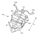
トレイ1は、その四方を側壁1A〜1Dで覆われているとともに、底部が底板1Eで配置されており、図1において上方のみが開放されている。トレイ1は複写機本体100に水平方向に形成されたトレイ収納空間部101に対して水平方向に着脱自在に挿入されている。図中矢印Cは、トレイ収納空間部101内に押し込んでトレイ1をセット位置へと移動するセット方向を示し、矢印Dはトレイ収納空間部101からトレイ1を引き出す引出方向を示し、符号Eはトレイ奥行方向を示す。引出方向D側に位置する側壁1Aには、後述する作業者Mが手をかける取っ手89が形成されている。本形態において、取っ手89が位置する側をトレイ1の手前側、側壁1Cが位置する側をトレイ奥側とする。また、側壁1Bと側壁1Dが位置する方向は、引出方向Dと平面視において直交するトレイ幅方向Fとする。
The tray 1 is covered on its four sides with side walls 1A to 1D, and the bottom is disposed with a bottom plate 1E. Only the upper part in FIG. 1 is open. The tray 1 is detachably inserted in a horizontal direction with respect to a tray storage space portion 101 formed in the horizontal direction in the copying machine main body 100. In the figure, an arrow C indicates a setting direction in which the tray 1 is pushed into the tray storage space 101 to move the tray 1 to a setting position, an arrow D indicates a drawing direction in which the tray 1 is pulled out from the tray storage space 101, and a symbol E indicates Indicates the tray depth direction. On the side wall 1A located on the drawing direction D side, a handle 89 on which a worker M to be described later applies is formed. In this embodiment, the side on which the handle 89 is located is the front side of the tray 1, and the side on which the side wall 1C is located is the back side of the tray. Further, the direction in which the side wall 1B and the side wall 1D are positioned is the tray width direction F that is orthogonal to the drawing direction D in plan view.
トレイ1の内部は、図11に示すように、トレイ奥側に配置された隔壁8,8,8によって4つに区分されている。区分された領域R1〜R4には、トナー収納容器70Y、70M、70C、70Kの先端側がそれぞれ収納される。区分された領域R1〜R4には、各トナー収納容器に対応するトナー吸引ノズル91がそれぞれ配置されている。各トナー吸引ノズル91は、トレイ1を引き出し際、少なくともその先端が露出する位置に配置されている。
As shown in FIG. 11, the inside of the tray 1 is divided into four parts by partition walls 8, 8, 8 arranged on the back side of the tray. In the divided areas R1 to R4, the front end sides of the toner storage containers 70Y, 70M, 70C, and 70K are stored, respectively. In the divided areas R1 to R4, toner suction nozzles 91 corresponding to the respective toner storage containers are respectively arranged. Each toner suction nozzle 91 is disposed at a position where at least the tip of the tray 1 is exposed when the tray 1 is pulled out.
本形態では画像形成装置がフルカラー対応機器であるため、4つのトナー収納容器70Y、70M、70C、70Kをトレイ1に収納する形態となるが、黒一色で印刷するモノクロの画像形成装置の場合には、黒トナーが収納されたトナー収納容器70Kのみがトレイ1に収納(セット)されることとなり、トレイ1を幅方向Eに狭くすることができる。このため、単色の画像形成装置の場合には、小サイズのシートを収納する給紙トレイの余剰空間にトナー収納容器を収納して、トナー収納容器とシートの共有トレイとしてもよい。また、同一段に並んで小サイズのトレイを2つ備えるようにし、一方をトナー収納容器用トレイ、他方をシート用トレイとする構成でもよい。各トナー収納容器の構成は同一構成であるので、以下トナーの色を識別するためのY、M、C、Kの符号は省略して説明する。
In this embodiment, since the image forming apparatus is a full-color device, the four toner storage containers 70Y, 70M, 70C, and 70K are stored in the tray 1. However, in the case of a monochrome image forming apparatus that prints in black. In other words, only the toner storage container 70K storing black toner is stored (set) in the tray 1, and the tray 1 can be narrowed in the width direction E. For this reason, in the case of a single-color image forming apparatus, the toner storage container may be stored in an excess space of a paper feed tray that stores a small size sheet, and the toner storage container and the sheet may be shared. Alternatively, two small-size trays may be provided in the same row, with one being a toner storage container tray and the other being a sheet tray. Since the configuration of each toner container is the same, the following description will be made by omitting the symbols Y, M, C, and K for identifying the color of the toner.
トナー収納容器70は、図4に示すように、少なくとも一部が可撓性材料からなる袋状であってトナー収納時に長方形状となる媒体収容部72と、複写機本体側に位置するトレイ1の奥側1Aの配設されたトナー吸引ノズル91と結合する口金部材71と、媒体収容部72に設けられ、図6〜図8に示す作業者Mに把持される把持部に相当するベルト部73と、トナー収納容器70単体のときに口金部材71に係合してトナーの飛散を防ぐキャップ74を備えている。このキャップ74は、トナー収納容器70をトレイ1に載置して収納する際には取り外される。図4において、矢印Aはトナー収納容器70の容器長手方向を、矢印Bはトナー収納容器70の幅方向をそれぞれ示す。
As shown in FIG. 4, the toner storage container 70 includes a medium storage portion 72 that is at least partially a bag shape made of a flexible material and has a rectangular shape when the toner is stored, and a tray 1 positioned on the copier body side. A base member 71 that is coupled to the toner suction nozzle 91 disposed on the back side 1A of the toner, and a belt portion that is provided in the medium storage portion 72 and corresponds to a gripping portion that is gripped by the worker M shown in FIGS. 73 and a cap 74 that engages with the base member 71 to prevent toner scattering when the toner container 70 is a single unit. The cap 74 is removed when the toner storage container 70 is placed on the tray 1 and stored. In FIG. 4, the arrow A indicates the container longitudinal direction of the toner storage container 70, and the arrow B indicates the width direction of the toner storage container 70.
口金部材71は、図4,図5に示すように、媒体収容部72の一方の端部となる先端72a(トナー収納容器の先端)に設けていられる。口金部材71は、断面L字状のベース部分71Aに筒状部分71Bが形成されたもので、筒状部分71Bの中央には排出口71Cが形成され、筒状部分71Bの外周面には、雄ねじ71Dが形成されている。雄ねじ71Dには、内側に雌ねじが形成された図4に示すキャップ74が締め込まれる。
As shown in FIGS. 4 and 5, the base member 71 is provided at a front end 72 a (a front end of the toner storage container) serving as one end of the medium storage unit 72. The base member 71 has a cylindrical portion 71B formed on a base portion 71A having an L-shaped cross section. A discharge port 71C is formed at the center of the cylindrical portion 71B. A male screw 71D is formed. A cap 74 shown in FIG. 4 having a female screw formed inside is fastened to the male screw 71D.
媒体収容部72の先端72aは、図5に示すように、トレイ1への装着時にセット方向側、すなわちトレイ1の奥側に位置される容器側面である。先端72aには、媒体収容部72内と連通する開口部72cが形成されている。口金部材71は、排出口71Dと開口部72cとが重なるように先端72aに固着されている。開口部72cには口金部材71に形成された弁ケース75が挿入されている。弁ケース75の内部には、開口部72cを開閉する弁体76が挿入されている。この弁体76は、弁ケース75で往復動可能に支持されていて、バネ77によって開口部72c閉じる方向に付勢されている。
As shown in FIG. 5, the front end 72 a of the medium accommodating portion 72 is a container side surface that is positioned on the set direction side, that is, on the back side of the tray 1 when mounted on the tray 1. An opening 72 c that communicates with the inside of the medium accommodating portion 72 is formed at the tip 72 a. The base member 71 is fixed to the tip 72a so that the discharge port 71D and the opening 72c overlap. A valve case 75 formed on the base member 71 is inserted into the opening 72c. A valve body 76 for opening and closing the opening 72c is inserted into the valve case 75. The valve body 76 is supported by a valve case 75 so as to be able to reciprocate, and is urged by a spring 77 in a direction to close the opening 72c.
このため、排出口71Cからトナー吸引ノズル91が挿入されると、弁体75はトナー吸引ノズル91の先端によって媒体収容部72内に向かって押し込まれ、開口部72cを開かれる。この状態でトナー補給装置10が作動することで、媒体収容部72内部のトナーが吸引可能とされることとなる。なお、符号71Eはノズル挿入時にトナー吸引ノズル91との間に隙間を形成しないためのスポンジなどで形成されたシール部材を示す。
For this reason, when the toner suction nozzle 91 is inserted from the discharge port 71 </ b> C, the valve body 75 is pushed into the medium accommodating portion 72 by the tip of the toner suction nozzle 91 and the opening 72 c is opened. When the toner replenishing device 10 operates in this state, the toner inside the medium accommodating portion 72 can be sucked. Reference numeral 71E denotes a seal member formed of a sponge or the like so as not to form a gap with the toner suction nozzle 91 when the nozzle is inserted.
図4に示すベルト部73は、容器長手方向Aに位置する一端側となる媒体収容部72の他方の端部となる後端72b側に設けられた第1のベルト73Aと、容器長手方向に位置する他端側となる先端72aから後端72b側に向かって伸びる第2のベルト73Bを備えている。
The belt portion 73 shown in FIG. 4 includes a first belt 73A provided on the rear end 72b side which is the other end portion of the medium accommodating portion 72 which is one end side positioned in the container longitudinal direction A, and a container longitudinal direction. A second belt 73B extending from the front end 72a, which is the other end side, to the rear end 72b side, is provided.
ベルト73Aはトナー収納容器70の幅方向Bに伸びていて、その両端が媒体収容部72に固定された短ベルトである。ベルト73Bはトナー収納容器70の容器長手方向Aに長く、その一端は後端72a側で、その他端は後端72b寄りで、それぞれ媒体収容部72に固定された長ベルトである。
The belt 73 </ b> A is a short belt extending in the width direction B of the toner storage container 70 and having both ends fixed to the medium storage portion 72. The belt 73B is a long belt that is long in the container longitudinal direction A of the toner storage container 70, one end of which is on the rear end 72a side and the other end is close to the rear end 72b, and is fixed to the medium storage unit 72.
口金部材71の樹脂材としては、ポリスチレン、ハイインパクトポリスチレン、ポリプロピレン、PET、ABS、または金属等があるが、袋部と同材質、または同系にすれば、両者は固着しやすく、またマテリアルリサイクルによる再利用がし易くなる。
As the resin material of the base member 71, there are polystyrene, high impact polystyrene, polypropylene, PET, ABS, metal, etc., but if they are made of the same material or the same material as the bag part, both are easily fixed, and also by material recycling. It becomes easy to reuse.
媒体収容部72とベルト73A,73Bの材質としては、ポリエステル、ポリエチレン、ポリウレタン,ポリプロピレン,ナイロン等からなる樹脂シートや、紙シートなどを用いることができる。容器本体の材質には、単層であるいは異種のものを複層に加工したもの、さらには紙上に樹脂をコーティングした牛乳パックのようなものも用いることができる。
As a material for the medium accommodating portion 72 and the belts 73A and 73B, a resin sheet made of polyester, polyethylene, polyurethane, polypropylene, nylon, or the like, a paper sheet, or the like can be used. As the material of the container main body, a single layer or a material obtained by processing different types into a plurality of layers, or a milk pack in which a resin is coated on paper can be used.
2層とも樹脂からなるものの場合、外部の圧力等によっても破れにくいものが好ましく、内側をポリエチレンのような軟性、外側をナイロン樹脂のような硬性のものからなるものが好適である。
In the case where both layers are made of resin, those which are not easily torn by an external pressure or the like are preferable, and those having a soft inner side such as polyethylene and a hard outer side such as nylon resin are preferable.
さらに、フレキシブル材料にアルミ蒸着するとか帯電防止剤を含有させて、静電気対策とすることもできる。フレキシブルな材料の厚さは特に限定的ではないが、厚すぎると柔軟性であるがための上述の利点が得られにくく、また薄すぎるとトナーが充填された部分がたるんでトナーの排出が十分に行われなくなることがあるため、好ましくは約20μm〜200μm,さらに約80μm〜150μmが適当である。
Furthermore, it is possible to take measures against static electricity by depositing aluminum on the flexible material or containing an antistatic agent. The thickness of the flexible material is not particularly limited, but if it is too thick, it is difficult to obtain the above-mentioned advantages due to its flexibility, and if it is too thin, the portion filled with the toner will sag and the toner will be discharged sufficiently. About 20 μm to 200 μm, and more preferably about 80 μm to 150 μm.
媒体収容部72は、所定の容器の形になるように、予め準備した複数のフレキシブルな材料片をヒートシール法等によって接着し形成した継ぎ目のあるものと、フレキシブルな材料がプラスチック樹脂の場合には、チューブ押し出し法で一体成型によって所定の形に形成される継ぎ目のないものが用いられる。先述のように、媒体収容部72には全体がフレキシブルな材料から形成されていない、一部が剛性の材料で形成される場合も、包含される。
The medium accommodating portion 72 has a joint formed by bonding a plurality of flexible material pieces prepared in advance by a heat seal method or the like so as to form a predetermined container, and when the flexible material is a plastic resin. Is a seamless one that is formed into a predetermined shape by integral molding using a tube extrusion method. As described above, the medium containing portion 72 includes a case where the entire portion is not formed of a flexible material but is partially formed of a rigid material.
また、媒体収納容器としてはトナー収納容器70に限定されるものではなく、例えば特開2006−178187号公報の段落「0026」から段落「0035」に記載されている、内部にトナーを収容する柔軟な袋部材を備え、この袋部材が、溶着容易な材料から成る溶着層と、気密性に優れた材料から成る気密層と、剛性に優れた材料から成る剛性層とを有するトナー収容体となるトナー容器80を用いてもよい。
Further, the medium storage container is not limited to the toner storage container 70, and is described in, for example, paragraphs “0026” to “0035” of Japanese Patent Application Laid-Open No. 2006-178187. The bag member is a toner container having a welding layer made of an easily weldable material, an airtight layer made of a material having excellent airtightness, and a rigid layer made of a material having excellent rigidity. A toner container 80 may be used.
このような可撓性を備えたトナー収納容器70はリサイクル性が良いが、剛性が低く、容器形状が定まり難くいため作業者Mが手で持ちにくいという課題があるが、ベルト部73を設けているので、容器形状が変形しても持ち易く、トレイ1への収納動作を容易に行えるというメリットがある。
The toner storage container 70 having such flexibility is good in recyclability, but has a problem that the rigidity of the toner storage container 70 is low and it is difficult for the operator M to hold the container shape by hand. Therefore, there is an advantage that even if the container shape is deformed, it can be easily held and the storing operation in the tray 1 can be easily performed.
つまり、トナー収納容器70をユーザーとなる作業者Mが使用する場合、運搬の際には、図6に示すように、中腰の状態でトナー収納容器70の先と後の端部のベルト73A、73Bを掴んで持ち上げることができる。ゆえにトナー収納容積が2リットル以上(トナー密度約0.6g/ccならトナー重量約1.2kg)、特に5リットル以上(同約3kg)といった重い容量でも簡単に運ぶことができる。トナー排出性の観点から流動性を上げるべく空気もそれなりに含めて密度を下げる必要があるが、そうすると容器自体の体積は大型化せざるを得ない。そうするとぐにゃぐにゃした状態で形状が定まらずに運び難くなるが、ベルト73A,73Bを備えることで、簡単に運べるようになる。特に長ベルトとなるベルト73Aは、運搬時と口金部材71をトレイ1内のトナー吸引ノズル1に位置あわせする際で把持位置を変えることで(位置あわせ時は、トナー排出口近くを持つ)運搬性とセット性を両立させることができる。
That is, when the operator M who is the user uses the toner storage container 70, when transporting, as shown in FIG. 6, as shown in FIG. 73B can be grabbed and lifted. Therefore, the toner can be easily transported even when the toner storage volume is 2 liters or more (the toner weight is about 1.2 kg when the toner density is about 0.6 g / cc), and particularly a heavy capacity of 5 liters or more (about 3 kg). From the viewpoint of toner dischargeability, it is necessary to reduce the density by including air as it is in order to increase the fluidity. However, the volume of the container itself must be increased. If it does so, it will become difficult to carry in a messy state without being fixed, but it becomes easy to carry by providing belts 73A and 73B. In particular, the belt 73A, which is a long belt, is transported by changing the gripping position when transporting and aligning the base member 71 with the toner suction nozzle 1 in the tray 1 (having the vicinity of the toner discharge port when positioning). And compatibility can be achieved.
ベルト部73の構成としては、図6に示すようなベルト73A(短ベルト)とベルト73B(長ベルト)の配置や組み合わせに限定されるものでない。例えば図7に示す形態は、トナー収納容器70の先端72aと後端72b近傍に、ベルト73A(短ベルト)をそれぞれ設けたものである。すなわち、図7に示すベルト部73は、容器長手方向Aに位置する媒体収容部72の両端となる先端72aと後端72b側にベルト73A(短ベルト)をそれぞれ設けた構成とされている。このため、可撓性材料のトナー収納容器70はリサイクル性が良いが、剛性が低く、容器の形状が定まり難くいため手で持ちにくいが、容器の両端にベルト73Aをそれぞれ設けることで、形状が変形する場合や容量が大きく重量がある場合でも持ち易くなり、画像形成装置への収納動作を容易に行える。また、トナー収納容器70のフレキシブル性を逆に利用することで、容器長手方向に長いトナー収納容器70でも2つ折にわざと座屈させて肩幅程度にし、ひじを伸ばした楽な状態で運ぶことが可能になる。
The configuration of the belt portion 73 is not limited to the arrangement or combination of the belt 73A (short belt) and the belt 73B (long belt) as shown in FIG. For example, in the form shown in FIG. 7, a belt 73A (short belt) is provided in the vicinity of the front end 72a and the rear end 72b of the toner storage container 70, respectively. That is, the belt portion 73 shown in FIG. 7 has a configuration in which a belt 73A (short belt) is provided on both the front end 72a and the rear end 72b side which are both ends of the medium accommodating portion 72 located in the container longitudinal direction A. For this reason, the toner storage container 70 made of a flexible material has good recyclability, but is difficult to hold by hand because of its low rigidity and difficulty in determining the shape of the container, but the shape can be reduced by providing belts 73A at both ends of the container. Even if it is deformed or has a large capacity and weight, it can be easily held and can be easily stored in the image forming apparatus. Further, by utilizing the flexibility of the toner storage container 70 in reverse, the toner storage container 70 that is long in the longitudinal direction of the container can be buckled on purpose to make it about the shoulder width and carried in an easy state with the elbow extended. It becomes possible.
ベルト部73の構成としては、図8に示すように、長ベルトであるベルト73Bのみであってもよい。この場合、容器長手方向に位置する媒体収容部72の両端となる先端72aと後端72bに、ベルト73Bの両端がそれぞれ固定する。
As a configuration of the belt portion 73, as shown in FIG. 8, only the belt 73B which is a long belt may be used. In this case, both ends of the belt 73B are fixed to the front end 72a and the rear end 72b which are both ends of the medium accommodating portion 72 located in the container longitudinal direction.
このような構成とすると、可撓性材料のトナー収納容器70はリサイクル性が良いが、剛性が低く、容器の形状が定まり難くいため手で持ちにくいが、ベルト73Bの両端をトナー収納容器70の両端に固定することで、ベルト73Bを作業者Mが肩からかけて片手で運ぶことができ、形状が変形する場合や容量が大きく重量がある場合でも運び易くなる。また、片手を自由に使えるため、トレイ1を引き出す際に、トナー収納容器70を下ろさなくて作業でき、収納動作を容易に行える。さらに、トレイ1へのセット時はベルト73Bの両端近傍をもち、トレイ内で後端72bを浮かせてトナー収納容器70をずらしつつ、先端72a側の口金部材71をトナー吸引ノズル91に位置あわせさせればよい(図14参照)。もちろん図6のトナー容器でも長ベルト73Bを肩に掛けての運搬は可能である。必要であれば、長ベルトを途中で2分し、ズボンに通すベルトのように長さを調節するバックル部とバックルの留め針を通す穴を複数設け肩に掛ける場合とトレイ内にセットする場合とで長さを調節できるようにてもよい。
In such a configuration, the toner storage container 70 made of a flexible material has good recyclability. However, the rigidity of the toner storage container 70 is low, and the shape of the container is difficult to determine. By fixing to both ends, the belt 73B can be carried by the worker M from the shoulder with one hand, and is easy to carry even when the shape is deformed or the capacity is large and heavy. Further, since one hand can be freely used, when the tray 1 is pulled out, the operation can be performed without lowering the toner container 70, and the storing operation can be easily performed. Further, when set on the tray 1, the belt 73 </ b> B is located near both ends, and the base member 71 on the front end 72 a side is aligned with the toner suction nozzle 91 while the rear end 72 b is floated in the tray and the toner storage container 70 is shifted. (See FIG. 14). Of course, the toner container of FIG. 6 can also be transported with the long belt 73B on the shoulder. If necessary, halve the long belt halfway, adjust the length like a belt that passes through trousers, multiple holes to pass through the buckle needle, and place it on the shoulder or set it in the tray You may be able to adjust the length.
次にトナー吸引ノズル91の構成について説明する。
Next, the configuration of the toner suction nozzle 91 will be described.
図11に示すように、トレイ1のセット方向Cに位置する奥側には、各色のトナー収納容器70の口金部材71に対応するように4つのトナー吸引ノズル91が配置されている。各トナー吸引ノズル91の構成は同一であるので、1つのノズル構成について図5を用いて説明する。
As shown in FIG. 11, four toner suction nozzles 91 are arranged on the back side of the tray 1 in the setting direction C so as to correspond to the cap members 71 of the toner storage containers 70 of the respective colors. Since each toner suction nozzle 91 has the same configuration, one nozzle configuration will be described with reference to FIG.
トナー吸引ノズル91は、図5に示すように、トレイ1の載置面となる底板1Eからトレイ内に突出して口金部材71に挿入されることで係合する係合側となるノズル本体911と、ノズル本体911と反対側となる底板1Eの外側に、ノズル本体911に対して回動自在に支持されている継ぎ手部912とを備えている。ノズル本体911は、パイプ材であって、底板1Eからほぼ垂直な基部911Aと、基部911Aに対してほぼ直角に屈曲されて水平状態を占めた挿入部911Bとから構成されていて、底板1Eに固定されている。継ぎ手部912は、いわゆるニップ部であって、トナーチューブ86の端部が挿入されてゴムバンドなどによって抜け止めがなされて装着されている。
As shown in FIG. 5, the toner suction nozzle 91 protrudes from the bottom plate 1 </ b> E serving as a mounting surface of the tray 1 into the tray and is inserted into the base member 71 to be engaged with a nozzle main body 911 that is engaged. A joint portion 912 that is rotatably supported with respect to the nozzle main body 911 is provided on the outer side of the bottom plate 1E that is opposite to the nozzle main body 911. The nozzle body 911 is a pipe material, and includes a base portion 911A that is substantially perpendicular to the bottom plate 1E, and an insertion portion 911B that is bent at a substantially right angle to the base portion 911A and occupies a horizontal state. It is fixed. The joint portion 912 is a so-called nip portion, and is attached with an end portion of the toner tube 86 inserted and prevented from being removed by a rubber band or the like.
挿入部911Bはトレイ1の矢印Cで示すトレイ引出方向に向かって配置されている。挿入部911Bには、口金部材71との係合部となるキャップ98が貫通して装着されていて、挿入部911Bを軸にしてキャップ98が回動可能に固定されている。挿入部911Bにはキャップ98のセット方向Dへの位置を規制するストッパ911Cがキャップ98の前後に形成されている。キャップ98は単体時のキャップ74と同径でかつ同ピッチの雌ねじがその内側に形成されている。
The insertion portion 911B is arranged in the tray pulling direction indicated by the arrow C of the tray 1. A cap 98 serving as an engaging portion with the base member 71 is inserted through the insertion portion 911B, and the cap 98 is rotatably fixed around the insertion portion 911B. The insertion portion 911 </ b> B is formed with stoppers 911 </ b> C that restrict the position of the cap 98 in the setting direction D before and after the cap 98. The cap 98 has a female screw having the same diameter and the same pitch as that of the cap 74 when it is a single unit.
このような構成によると、トレイ1にトナー収納容器70を載置してセット方向Dに移動させて挿入部911Bを口金部材71の排出口71Cへと挿入する。そして、ねじ溝71Dにキャップ98を締め込むことで、トナー収納容器70がトレイ1上に固定される。
According to such a configuration, the toner storage container 70 is placed on the tray 1 and moved in the setting direction D, and the insertion portion 911 B is inserted into the discharge port 71 C of the base member 71. The toner storage container 70 is fixed on the tray 1 by tightening the cap 98 in the thread groove 71D.
このようなトナー吸引ノズル91の構成であると、後述する押し上げ部材3でトナーがノズル内を押圧し、その反作用でトナー収納容器70がトナー吸引ノズル91から抜けようとする作用が生じても、口金部材71がキャップ98との締結によってトレイ1に保持されるので、トナー収納容器70のずれによるトナー飛散を防止することができる。
With such a configuration of the toner suction nozzle 91, even if the toner presses the inside of the nozzle by the push-up member 3 to be described later, and the reaction causes the toner storage container 70 to come out of the toner suction nozzle 91, Since the base member 71 is held on the tray 1 by being fastened to the cap 98, the scattering of the toner due to the deviation of the toner storage container 70 can be prevented.
また、継ぎ手部912部分が回転自在となっているので、トレイ1をセット位置へと押し込んだときに、弛んだトナーチューブ86が継ぎ手部912との間で突っ張ることがなく、良好にトレイ1の移動を行うことができ、操作性がよい。
Further, since the joint portion 912 is rotatable, when the tray 1 is pushed into the set position, the loose toner tube 86 does not stretch between the joint portion 912 and the tray 1 can be satisfactorily improved. It can be moved and has good operability.
図9、図10は口金部材の構成が異なるトナー収納容器を示す。このトナー収納容器701は、基本的には特開2006−178187号公報の段落「0026」から段落「0035」に記載されているトナー容器80の構成とされている。
9 and 10 show toner storage containers having different cap member configurations. The toner container 701 is basically configured as the toner container 80 described in paragraphs “0026” to “0035” of Japanese Patent Application Laid-Open No. 2006-178187.
トナー収納容器701の口金部材710は、図10に示すように、媒体収納部72内と連通する排出口711Aが断面L字状に形成されていて、弁体76を図10においてセット方向Cと直交するに移動させることで、排出口711Aを開閉するように構成されている。すなわち、排出口711Aは、媒体収納部72内と連通するトナー導入部711Aaとトナー導入部711Aaと連通するトナー落下部711Abとから構成されている。本形態において、トナー導入部711Aaはトナー収納容器701をトレイ1に載置した際に略水平状態となり、トナー落下部711Abは略垂直状態となるように形成されている。トナー落下部711Abの上部には弁ケース75がトナー落下部711Abとつながるように形成されている。弁ケース75とトナー落下部711Abには、軸状の弁体76が上下方向に移動可能に支持されていて、弁ケース75内に挿入されたバネ77によってトナー導入部711Aaとトナー落下部711Abを閉じる方向に付勢されている。弁体76のストローク量は、トナー吸引ノズル91によって押されて図10において上方に移動した際に、トナー導入部711Aaとトナー吸引ノズルとが連通可能となる量とされている。
As shown in FIG. 10, the base member 710 of the toner storage container 701 has a discharge port 711 </ b> A communicating with the inside of the medium storage portion 72 having an L-shaped cross section. It is configured to open and close the discharge port 711A by moving it orthogonally. In other words, the discharge port 711A includes a toner introducing portion 711Aa that communicates with the inside of the medium storage portion 72 and a toner dropping portion 711Ab that communicates with the toner introducing portion 711Aa. In this embodiment, the toner introduction portion 711Aa is formed to be substantially horizontal when the toner storage container 701 is placed on the tray 1, and the toner dropping portion 711Ab is formed to be substantially vertical. A valve case 75 is formed above the toner dropping part 711Ab so as to be connected to the toner dropping part 711Ab. A shaft-like valve body 76 is supported on the valve case 75 and the toner dropping part 711Ab so as to be movable in the vertical direction, and the toner introduction part 711Aa and the toner dropping part 711Ab are connected by a spring 77 inserted into the valve case 75. It is biased in the closing direction. The stroke amount of the valve body 76 is set such that the toner introduction portion 711Aa and the toner suction nozzle can communicate with each other when the valve body 76 is pushed by the toner suction nozzle 91 and moves upward in FIG.
このような口金部材711を有するトナー収納容器701に対応するトナー吸引ノズルの構成としては、図10に示すように、図5に示す挿入部911Bを備えず、トレイ1の底板1Eから上方に向かって突出するパイプ状でその一部が開口されたノズル本体911Dを挿入部とするナー吸引ノズル91Aとなる。
As shown in FIG. 10, the toner suction nozzle corresponding to the toner container 701 having such a cap member 711 is not provided with the insertion portion 911B shown in FIG. 5, and is directed upward from the bottom plate 1E of the tray 1. Thus, the nozzle suction nozzle 91 </ b> A having a nozzle main body 911 </ b> D having a partially opened pipe shape as an insertion portion is formed.
このような構成において、トレイ1にトナー収納容器701をセットする場合、ノズル本体911Dとトナー落下部711Abとの位置を合わせて上方からトナー収納容器701をトレイ1に載置する。すると、基ノズル本体911Dがトナー落下部711Ab内に進入して弁体76を押し上げて、トナー導入部711Aaとトナー落下部711Abとノズル本体911Dの開口部と連通する。本形態の場合、媒体収容部72と口金部材711との連結部での媒体移動方向に対して角度を持って突出する係合部はノズル本体911Dで構成される。
In such a configuration, when the toner storage container 701 is set in the tray 1, the toner storage container 701 is placed on the tray 1 from above by aligning the positions of the nozzle body 911D and the toner dropping portion 711Ab. Then, the base nozzle main body 911D enters the toner dropping portion 711Ab and pushes up the valve body 76 to communicate with the toner introducing portion 711Aa, the toner dropping portion 711Ab, and the opening of the nozzle main body 911D. In the case of this embodiment, the engaging portion that protrudes at an angle with respect to the medium moving direction at the connecting portion between the medium accommodating portion 72 and the base member 711 is constituted by a nozzle body 911D.
このようなトナー吸引ノズル91Aと口金部材711の構成であると、後述する押し上げ部材3でトナーがノズル内を押圧し、その反作用でトナー収納容器701がトナー吸引ノズル91Aから抜けようとする作用が生じても、口金部材711とノズル本体911Dとの挿入状態による締結によってトレイ1に保持されるので、トナー収納容器701のずれによるトナー飛散を防止することができる。なお、図10に示すノズル形態においても、図5に示す場合と同様に、ノズル本体911Dと反対側となる底板1Eの外側に、ノズル本体911Dに対して回動自在に支持されている継ぎ手部912とを備える構成としてもよい。
With such a configuration of the toner suction nozzle 91A and the base member 711, the toner presses the inside of the nozzle by the push-up member 3 which will be described later, and the reaction causes the toner storage container 701 to come out of the toner suction nozzle 91A. Even if it occurs, since it is held on the tray 1 by fastening by the insertion state of the base member 711 and the nozzle main body 911D, toner scattering due to the deviation of the toner storage container 701 can be prevented. In the nozzle configuration shown in FIG. 10 as well, as in the case shown in FIG. 5, the joint portion that is rotatably supported with respect to the nozzle body 911 </ b> D outside the bottom plate 1 </ b> E opposite to the nozzle body 911 </ b> D. 912 may be provided.
図10に示すトナー収納容器701の場合には、ベルト73Aを弁ケース75と容器の後端72bに装着するようにしてもよい。この場合トレイ1内に立設されたノズル本体911Dを上方から狙って口金部材711を落とし込む際にセットし易くなる。
In the case of the toner storage container 701 shown in FIG. 10, the belt 73A may be attached to the valve case 75 and the rear end 72b of the container. In this case, it becomes easy to set when the nozzle member 711 is dropped while aiming at the nozzle body 911D standing in the tray 1 from above.
トレイ1内でのトナー収納容器701の位置決めについては、図9に示すトレイ1の幅方向Fに位置する口金部材711の側面711a,711bに半円弧状の溝部715,715をそれぞれ形成し、これら溝部715,715に挿入可能な位置決めピン716、716をトレイ1上に設置しても達成することができる。
Regarding positioning of the toner container 701 in the tray 1, semicircular arc-shaped grooves 715 and 715 are formed on the side surfaces 711a and 711b of the base member 711 located in the width direction F of the tray 1 shown in FIG. This can also be achieved by installing positioning pins 716 and 716 that can be inserted into the grooves 715 and 715 on the tray 1.
次に、移動促進手段2の構成について図11から図14を用いて説明する。
Next, the structure of the movement promotion means 2 is demonstrated using FIGS. 11-14.
移動促進手段2は、トレイ1をセット位置に向かって挿入するのと連動してトナー吸引ノズル91と反対側のトレイ手前側においてトナー収納容器70の媒体収納部72を下方から押し上げ方向に動作可能な押し上げ部材3と、押し上げ部材3に押し上げ力を付与する弾性部材となる圧縮コイルバネ4と、最大引き出し位置からセット位置へのトレイ1の移動途中までは、押し上げ部材3の押し上げ動作を制限し、トレイ1がセット位置を占める際に、複写機本体100側に配置したカムレール103,103との協動によって押し上げ動作を開放する押上動作制御機構とを備えている。そして、これら押し上げ部材3、圧縮コイルバネ4、押上動作制御機構はトレイ1に設けられている。
The movement promoting means 2 can operate in the direction in which the medium storage portion 72 of the toner storage container 70 is pushed up from below on the front side of the tray opposite to the toner suction nozzle 91 in conjunction with the insertion of the tray 1 toward the set position. The push-up member 3, the compression coil spring 4 serving as an elastic member for applying a push-up force to the push-up member 3, and the push-up operation of the push-up member 3 are limited until the tray 1 is moved from the maximum pull-out position to the set position, When the tray 1 occupies the set position, there is provided a push-up operation control mechanism that releases the push-up operation in cooperation with the cam rails 103 and 103 arranged on the copying machine main body 100 side. The push-up member 3, the compression coil spring 4, and the push-up operation control mechanism are provided in the tray 1.
押し上げ部材3は、トレイ奥側に位置する隔壁8とトレイ手前側の側壁1Aとの間に配置される押し上げ部材であって、ベース板3Aと、ベース板3Aの幅方向Eに一対の側板3B,3Cが立設されている。各トナー収納容器70は、このベース板3A上に載置される。押し上げ部材3は、金属や樹脂等で形成し、圧縮コイルバネ4の押圧で変形しないものがよい。
The push-up member 3 is a push-up member disposed between the partition wall 8 located on the back side of the tray and the side wall 1A on the near side of the tray, and includes a base plate 3A and a pair of side plates 3B in the width direction E of the base plate 3A. , 3C is erected. Each toner storage container 70 is placed on the base plate 3A. The push-up member 3 is preferably made of metal, resin, or the like and does not deform when pressed by the compression coil spring 4.
トレイ奥側に位置する側板3B,3Cの上部には、トレイ1の側壁1Bと側壁1Dにそれぞれ形成された支持穴9A,9Bに回転可能に挿入されるピン10A、10Bが同軸線上に形成されている。押し上げ部材3は、これら支持穴9A,9Bにピン10A、10Bを挿入することで、トレイ1にピン10A、10Bを中心にして上下に揺動自在に支持される。
Pins 10A and 10B that are rotatably inserted into support holes 9A and 9B respectively formed in the side wall 1B and side wall 1D of the tray 1 are formed on the same axis on the upper side plates 3B and 3C located on the back side of the tray. ing. The push-up member 3 is supported by the tray 1 so as to be swingable up and down around the pins 10A and 10B by inserting the pins 10A and 10B into the support holes 9A and 9B.
ベース板3Aのトレイ手前に位置する後端3A1側には、ベース板3Aから幅方向Eに突出する突起11A,11Bが形成されている。これら突起11A,11Bの下方には、幅方向Fに伸びる渡り棒12が、ベース板3Aに固定されて配置されている。渡り棒12は、ベース板3Aの平面性を維持するために突起11A,11Bの裏に配置したもので、ベース板3A単体で強度を出せて捻れなどが発生しないで平面性を確保できる場合には省略することができる。
Projections 11A and 11B projecting in the width direction E from the base plate 3A are formed on the side of the rear end 3A1 located in front of the tray of the base plate 3A. Below these protrusions 11A and 11B, a crossing bar 12 extending in the width direction F is fixed to the base plate 3A. The crossover bar 12 is disposed behind the protrusions 11A and 11B in order to maintain the flatness of the base plate 3A. When the base plate 3A alone can increase the strength and the flatness can be ensured without generating twist. Can be omitted.
これら突起11A,11Bと渡り棒12の両端は、トレイ1の互いに対向する側壁1B、1Dに形成された円弧状の長孔13A,13Bに挿通されていて、押し上げ部材3の揺動範囲を規制している。
Both ends of the projections 11A and 11B and the crossing bar 12 are inserted into arc-shaped elongated holes 13A and 13B formed in the side walls 1B and 1D facing each other of the tray 1 to restrict the swing range of the push-up member 3. is doing.
圧縮コイルバネ4は、図12,図13に示すように、その一端をトレイ1の底板1Eに固定されて底板1Eとベース板3Aの間に介装されていて、ピン10A、10Bを中心にしてベース板3Aの後端3A1が図14に示すように上方に持ち上がるように配置されている。
As shown in FIGS. 12 and 13, one end of the compression coil spring 4 is fixed to the bottom plate 1E of the tray 1 and is interposed between the bottom plate 1E and the base plate 3A, with the pins 10A and 10B as the center. The rear end 3A1 of the base plate 3A is disposed so as to be lifted upward as shown in FIG.
本形態において、圧縮コイルバネ4は幅方向Eに直線的3つ配置していて、トナー収納容器70内のトナー量が満杯の重い時(新品の時)でもトレイ1がセット位置を占めたときに、図15(d)に示すように、トナー収納容器70を十分に持ち上げてトレイ収納空間101の上部に位置する本体側天井面102に媒体収納部72が当接するように、バネ力が設定されている。このバネ力を確保されるのであれば、圧縮コイルバネ4の個数や配置は自由に設定することができる。つまり、本形態では、押し上げ部材3に載置されるトナー収納容器全ての満杯時においても押し上げ部材3を持ち上げられるバネ力に設定されているため、補給動作によって収納されるトナー量が徐々に少なくなるのに追従して、媒体収納部72をトレイ1の上方に位置する本体側天井面102に押し付けることができる。本体側天井面102は、複写機本体100に押し込まれたトレイ1の上方に配置され、押し上げ部材3によって押し上げられた媒体収納部72を、押し上げ部材3とで挟んで圧縮する圧縮部を構成する。
In this embodiment, three compression coil springs 4 are arranged linearly in the width direction E, and the tray 1 occupies the set position even when the toner amount in the toner container 70 is full (when new). As shown in FIG. 15D, the spring force is set so that the toner storage container 70 is sufficiently lifted so that the medium storage portion 72 comes into contact with the main body-side ceiling surface 102 located above the tray storage space 101. ing. As long as this spring force is secured, the number and arrangement of the compression coil springs 4 can be freely set. That is, in this embodiment, since the spring force is set so that the push-up member 3 can be lifted even when all of the toner storage containers placed on the push-up member 3 are full, the amount of toner stored by the replenishment operation is gradually reduced. Following this, the medium storage portion 72 can be pressed against the main body side ceiling surface 102 located above the tray 1. The main body-side ceiling surface 102 is disposed above the tray 1 pushed into the copying machine main body 100 and constitutes a compression unit that compresses the medium storage unit 72 pushed up by the push-up member 3 with the push-up member 3 interposed therebetween. .
図11、図12に示すように、トレイ1の側壁1Bと側壁1Dの側には、トレイ奥行方向Fに長い一対のレバー61,62が配置されている。レバー61,62はトレイ奥側に位置する先端61A、62Aにカムレール103、103(図12参照)と当接するガイドピン63A、63Bが幅方向Eに突出するように設けられている。レバー61,62は、側壁1Bと側壁1Dに回転自在に支持された押し上げ部材3のピン10A、10Bによってそれぞれ揺動自在に支持されていて、トレイ手前側に対置するレバー61,62の後端61B,62Bが、長孔13A,13Bから幅方向Eに突出している突起11A,11Bの上方に当接可能に配置されている。レバー61,62には、圧縮コイルバネ4のバネ力に抗して後端61B,62Bで突起11A,11Bを押し下げる方向にレバー61,62を付勢する付勢力が作用している。この付勢力は、一端が後端61B,62Bとレバーの揺動中心との間に係止され、他端がトレイ1側に係止された付勢手段となる引っ張りコイルバネ64A,64Bによって付与されている。
As shown in FIGS. 11 and 12, a pair of levers 61 and 62 that are long in the tray depth direction F are arranged on the side wall 1 </ b> B and side wall 1 </ b> D side of the tray 1. The levers 61 and 62 are provided at the leading ends 61A and 62A located on the back side of the tray so that guide pins 63A and 63B that contact the cam rails 103 and 103 (see FIG. 12) protrude in the width direction E. The levers 61 and 62 are swingably supported by the pins 10A and 10B of the push-up member 3 rotatably supported on the side wall 1B and the side wall 1D, respectively, and the rear ends of the levers 61 and 62 facing the front side of the tray 61B and 62B are arrange | positioned so that contact | abutting is possible above protrusion 11A, 11B which protrudes in the width direction E from long hole 13A, 13B. The levers 61 and 62 are applied with a biasing force that biases the levers 61 and 62 in a direction in which the protrusions 11A and 11B are pushed down by the rear ends 61B and 62B against the spring force of the compression coil spring 4. This urging force is applied by tension coil springs 64A and 64B serving as urging means having one end locked between the rear ends 61B and 62B and the swing center of the lever and the other end locked to the tray 1 side. ing.
押し上げ部材3は、このレバー61,62とレバーに付与される付勢力によって、トレイ1が引き出された状態では、図13に示すように、後端3A1側が底板1E側に位置するように保持されている。そしてレバー先端のガイドピン63A、63Bがカムレール103,103によって押し下げられると、図14に示すように、レバー61,62が解除方向に回転することで、後端61B,62Bによる突起11A,11Bを押し下げる作用が解除され、圧縮コイルバネ4のバネ力によって後端3A1側が底板1Eから上方に持ち上げられる。カムレール103,103は、図12に示すように、側壁1Bと側壁1Dにそれぞれ対向するトレイ収納空間101の側面101A、101Bに設けられている。カムレール103,103による押し上げ部材3の押し上げ規制の解除開始時期、すなわちガイドピン63A、63Bの押し下げに寄与するカムレール103のカム面(傾斜面)の開始位置は、トナー収納容器70の口金部材72とトナー吸引ノズル91とが連結されたトレイ1のセット位置、あるいはその直前で解除できるように設定するのが好ましい。と言うのも押し上げ部材3がセット位置からまだ距離を残す位置で上げられしまうと、本体側天井面102でトナー収納容器70を押圧しながらトレイ1が走行する距離が長くなり、トナー収納容器70にダメージを与えてしまいかねないからである。
When the tray 1 is pulled out by the levers 61 and 62 and the biasing force applied to the lever, the push-up member 3 is held so that the rear end 3A1 side is positioned on the bottom plate 1E side as shown in FIG. ing. When the guide pins 63A and 63B at the end of the lever are pushed down by the cam rails 103 and 103, as shown in FIG. 14, the levers 61 and 62 are rotated in the releasing direction, so that the protrusions 11A and 11B by the rear ends 61B and 62B are The push-down action is released, and the rear end 3A1 side is lifted upward from the bottom plate 1E by the spring force of the compression coil spring 4. As shown in FIG. 12, the cam rails 103 and 103 are provided on the side surfaces 101A and 101B of the tray storage space 101 facing the side wall 1B and the side wall 1D, respectively. The release start timing of the lifting restriction of the push-up member 3 by the cam rails 103, 103, that is, the start position of the cam surface (inclined surface) of the cam rail 103 that contributes to the push-down of the guide pins 63A, 63B is the same as the base member 72 of the toner storage container 70 It is preferable to set so that it can be released immediately before or at the set position of the tray 1 to which the toner suction nozzle 91 is connected. In other words, if the push-up member 3 is lifted at a position that still leaves the set position, the distance that the tray 1 travels increases while the toner storage container 70 is pressed by the main body-side ceiling surface 102, and the toner storage container 70. Because it can damage it.
本形態において、押上動作制御機構は突起11A,11B、渡り棒12、レバー61,62、引っ張りコイルバネ64A,64Bによって構成されている。
In this embodiment, the push-up operation control mechanism is constituted by protrusions 11A and 11B, a crossing bar 12, levers 61 and 62, and tension coil springs 64A and 64B.
このような構成において、トレイ1にトナー収納容器70を新規にセットする場合、図15(a)に示すように、トレイ収納空間部101内に押し込まれているトレイ1を、作業者Mが取っ手89を持って引出方向Cに引き最大引出位置まで移動する。最大引出位置とは、トレイ収納空間101内にトレイ1の先端が位置し、作業者Mがトレイ1を支えなくても自力で支持される位置である。そして、この位置をトレイ1が占めると、トナー吸引ノズル91はトレイ収納空間101外に露出するので、作業者Mが外側から目視することができる。このため、トレイ1の上方からの作業者Mによるトナー吸引ノズル91とトナー収納容器70の口金部材71の係合動作の視認性が飛躍的によくなる。また、ガイドピン63A、63Bは図16(a)に示すようにカムレール103のカム面103Aとは接触していない。
In such a configuration, when the toner storage container 70 is newly set in the tray 1, as shown in FIG. 15A, the operator M handles the tray 1 pushed into the tray storage space 101. Hold the 89 and move in the pulling direction C to the maximum pulling position. The maximum pull-out position is a position where the front end of the tray 1 is located in the tray storage space 101 and is supported by the worker M without supporting the tray 1 by himself / herself. When the tray 1 occupies this position, the toner suction nozzle 91 is exposed to the outside of the tray storage space 101, so that the worker M can see from the outside. Therefore, the visibility of the engagement operation between the toner suction nozzle 91 and the base member 71 of the toner storage container 70 by the worker M from above the tray 1 is dramatically improved. Further, the guide pins 63A and 63B are not in contact with the cam surface 103A of the cam rail 103 as shown in FIG.
トナー収納容器70は上述したように、可撓性材料ゆえ、弛み易く、トナー吸引ノズル91と口金部材71とを係合させるのが難しい。しかし、図15(a)に示すように、トナー収納容器70に容器長手方向と略並行に取り付けられたベルト73B(長ベルト)と口金部材71と反対側の端部に取り付けられたベルト73A(短ベルト)を採用しているので持ち易い。また、トレイ1は作業者Mから見て見下ろす位置にあり、上記のような配置と構成のベルトを備えることで、作業者Mは自然と容器上方からトナー収納容器70を把持し、トレイ1内へ容易に収納することができる。収納されたトナー収納容器70は、図15(b)に示すように、トレイ1内でその後端72bを持ち上げながらトナー吸引ノズル91に向かってずらし、トナー吸引ノズル91の先端に口金部材71を係合させて連結する。その際、ベルト73B(長ベルト)のトナー排出口近傍を把持して寄せるのがやり易い。
As described above, since the toner container 70 is a flexible material, it is easy to loosen and it is difficult to engage the toner suction nozzle 91 and the base member 71. However, as shown in FIG. 15A, a belt 73B (long belt) attached to the toner storage container 70 substantially parallel to the longitudinal direction of the container and a belt 73A (attached to the end opposite to the base member 71). A short belt is easy to hold. Further, the tray 1 is in a position to be looked down from the worker M, and by providing the belt having the above arrangement and configuration, the worker M naturally grips the toner storage container 70 from above the container, and the tray 1 Can be stored easily. As shown in FIG. 15B, the stored toner storage container 70 is shifted toward the toner suction nozzle 91 while raising the rear end 72 b in the tray 1, and the base member 71 is engaged with the tip of the toner suction nozzle 91. Connect them together. At this time, it is easy to grip and move the vicinity of the toner discharge port of the belt 73B (long belt).
トレイ1内へ収納されたトナー収納容器70の先端側は、図11に示す隔壁8によって仕切られた区画R1からR4内の底板1E上に直接載置されるが、トナー収納容器70の後端72b側は図13に示すようにレバー61,62によって押し下げられている押し上げ部材3の上に載置される。このため、載置したときにぶらぶらしないので、トナー収納容器70の座りがよく、図15(b)に示すようにトナー吸引ノズル91に向かってずらし際も移動し易いので、セット性がよい。
The front end side of the toner storage container 70 stored in the tray 1 is directly placed on the bottom plate 1E in the sections R1 to R4 partitioned by the partition wall 8 shown in FIG. The side 72b is placed on the push-up member 3 pushed down by the levers 61 and 62 as shown in FIG. For this reason, since the toner container 70 is not hung when placed, the toner container 70 can be sat satisfactorily, and as shown in FIG.
次にトナー収納容器70をセットされたトレイ1を図15(c)に示すようにセット方向Cに向かって押し込むと、トレイ1がトレイ収納空間部101内を移動する。このとき、押し上げ部材3は、図16(b)に示すように、レバー61,62の先端に設けたガイドピン63A、63Bがカムレール103、103と当接するまでは押し下げられた状態であるので、本体側天井面102にトナー収納容器70がひっ掛かることがなく、トレイ1をセット位置へスムーズに移動することができる。
Next, when the tray 1 in which the toner storage container 70 is set is pushed in the setting direction C as shown in FIG. 15C, the tray 1 moves in the tray storage space 101. At this time, as shown in FIG. 16B, the push-up member 3 is pushed down until the guide pins 63A and 63B provided at the tips of the levers 61 and 62 come into contact with the cam rails 103 and 103. The toner storage container 70 is not caught on the main body side ceiling surface 102, and the tray 1 can be smoothly moved to the set position.
トレイ1の移動が進み、図16(c)に示すように、ガイドピン63A、63Bとカムレール103、103と係合すると、カムレールのカム面103Aによってガイドピン63A、63Bが押し下げられる。この作用によってレバー61,62は、後端61B,62Bを持ち上げる方向に回動するので、図15(d)に示すように、レバー後端によって上方への移動が規定されていた押し上げ部材3が圧縮コイルバネ4のバネ力によって押し上げられる。すると、トナー収納容器70は、押し上げ部材3によって主に媒体収納部72の後半部分が押し上げられる。このため、押し上げ部材3は、トナー収納容器70内のトナーが排出されるにつれて圧縮コイルバネ4によって上方に押し上げられるので、その傾斜が口金部材71に向かって急になり、収納されているトナーが少なくなっても排出性を維持することができる。
As the movement of the tray 1 proceeds and the guide pins 63A and 63B engage with the cam rails 103 and 103 as shown in FIG. 16C, the guide pins 63A and 63B are pushed down by the cam surface 103A of the cam rail. By this action, the levers 61 and 62 are rotated in the direction of lifting the rear ends 61B and 62B. Therefore, as shown in FIG. 15 (d), the push-up member 3 whose upward movement is regulated by the rear end of the lever is provided. It is pushed up by the spring force of the compression coil spring 4. Then, the toner container 70 is pushed up mainly by the push-up member 3 in the latter half of the medium container 72. For this reason, the push-up member 3 is pushed upward by the compression coil spring 4 as the toner in the toner storage container 70 is discharged, so that the inclination of the push-up member 3 becomes steep toward the base member 71 and the stored toner is small. Even if it becomes, discharge property can be maintained.
つまり、押し上げ部材3は、トレイ1をセット位置へと押し込んだときに、媒体排出部と反対側の媒体収納部72を下方から押し上げて媒体収納部72を垂直方向に曲げるように変形させるので、媒体収納部72のトナーが自重で落下するため、従来のようなスクリューなどの搬送手段などを用いることなく、トナーを口金部材71へと移動することができ、可撓性のトナー収納容器70であってもトナーの排出性が向上する。
That is, when the tray 3 is pushed into the set position, the push-up member 3 is deformed so as to push up the medium storage portion 72 on the side opposite to the medium discharge portion from below and bend the medium storage portion 72 in the vertical direction. Since the toner in the medium storage unit 72 falls by its own weight, the toner can be moved to the base member 71 without using a conventional conveying means such as a screw. Even if it exists, the toner discharge performance is improved.
さらに、押し上げ部材3が押し上げられると、押し上げ部材3と本体側天井面102とに媒体収納部72を挟まれ、可撓性の媒体収納部72の壁を有することを利用して容器内圧を高めることができるので、トナーの排出性をより向上させることができる。
Further, when the push-up member 3 is pushed up, the medium storage portion 72 is sandwiched between the push-up member 3 and the main body-side ceiling surface 102, and the internal pressure of the container is increased by utilizing the wall of the flexible medium storage portion 72. Therefore, the toner discharge performance can be further improved.
一方、押し上げ部材3が押し上げられても、トナー収納容器70の前半部分は区画R1〜R4内の底板1E上にそれぞれ載置されているので、略水平状態のままである。このため、トナー満杯時においては、口金部材71側に対するトナーの移動が少なく、口金部材71側でのトナーの凝集がなく、凝集による吸引不良の発生を抑制することができる。
On the other hand, even when the push-up member 3 is pushed up, the first half of the toner storage container 70 is placed on the bottom plate 1E in each of the sections R1 to R4, so that it remains in a substantially horizontal state. For this reason, when the toner is full, there is little movement of the toner with respect to the base member 71 side, there is no toner aggregation on the base member 71 side, and the occurrence of suction failure due to aggregation can be suppressed.
図11から図14に示す移動促進手段2では、レバー61,62に付勢力を与える引っ張りコイルバネ64A,64Bを、後端61B,62Bとレバーの揺動中心との間に配置したが、例えば図17に示すように、バネの一端を先端61A、62Aとレバーの揺動中心との間に係止したコイルバネ64C,64Dの他端をトレイ1に係止するように配置してもよい。この場合、カムレール103のカム面は、図16の場合と上下反対に配置し、セット位置直前でカム面が下がるように形成する。
In the movement promoting means 2 shown in FIGS. 11 to 14, the tension coil springs 64A and 64B for applying an urging force to the levers 61 and 62 are arranged between the rear ends 61B and 62B and the swing center of the lever. 17, the other ends of the coil springs 64 </ b> C and 64 </ b> D in which one end of the spring is locked between the tips 61 </ b> A and 62 </ b> A and the swing center of the lever may be arranged to be locked in the tray 1. In this case, the cam surface of the cam rail 103 is arranged upside down as in FIG. 16, and is formed so that the cam surface is lowered immediately before the set position.
このような構成とすると、図17(a)に示すようにトレイ1を引き出した状態ではカムレール103にガイドピン63A、63Bが乗り上げているのでレバー61A、61Bが押し下げられており、結果、押し上げ部材3のトナー収納容器70が載置される面は水平になるよう維持されている。これによりトナー収納容器70のセットはしやすくなっている。トナー収納容器70をトレイ1内に収納し、図17(b)に示すようにトレイ1を押し込み操作すると、セット位置直前のカム面が下がる傾斜面にガイドピン63A、63Bが掛かったときからレバー61,62の後端61B,62Bが引っ張りコイルバネ64A,64Bと押し上げ部材3の下方に設置した圧縮コイルバネ4から押し上げ部材3の両側の突起11A,11Bを経て伝えられる押上げ力によって上方に上がる。このため、図17(c)に示すように最終的にセット位置にトレイ1が至った際には、媒体収納部72の後半部分が本体側天井面102と押し上げ部材3との間で挟まれて、トナーを口金部材71側に移動させる内、レバー61,62の上がり具合に追従せず、それ以降はコイルバネ64C,64Dがレバー61,62を上げる。
With such a configuration, as shown in FIG. 17A, when the tray 1 is pulled out, the guide pins 63A and 63B are riding on the cam rail 103, so that the levers 61A and 61B are pushed down. The surface on which the third toner storage container 70 is placed is kept horizontal. This facilitates setting of the toner storage container 70. When the toner storage container 70 is stored in the tray 1 and the tray 1 is pushed in as shown in FIG. 17B, the lever is started from when the guide pins 63A and 63B are hooked on the inclined surface where the cam surface just before the setting position is lowered. The rear ends 61B and 62B of 61 and 62 are raised upward by the pushing force transmitted from the tension coil springs 64A and 64B and the compression coil spring 4 installed below the push-up member 3 through the protrusions 11A and 11B on both sides of the push-up member 3. For this reason, as shown in FIG. 17C, when the tray 1 finally reaches the set position, the latter half of the medium storage portion 72 is sandwiched between the main body-side ceiling surface 102 and the push-up member 3. Thus, while the toner is moved to the base member 71 side, the levers 61 and 62 are not followed up, and the coil springs 64C and 64D raise the levers 61 and 62 thereafter.
画像形成にトナーが消費されるとトナー収納容器70は体積を減少する。そうすると押し上げ部材3は圧縮コイルバネ4の作用でさらにトナー収納容器70の媒体収納部72を押し上げるが、レバー61,62がその際、干渉しないようにより高い位置まで引っ張りコイルバネ64A,64Bで持ち上げられるので、レバー61,62が突起11A,11Bに干渉して押し上げ作用を途中で阻害することがなくなる。このため、トナーの残量が少なくなった場合でもトナーを口金部材71へと移動することができ、使用最後までトナーの排出性を維持することができる。
When the toner is consumed for image formation, the toner container 70 decreases in volume. Then, the push-up member 3 further pushes up the medium storage portion 72 of the toner storage container 70 by the action of the compression coil spring 4, but the levers 61 and 62 are lifted to the higher position by the tension coil springs 64A and 64B so that they do not interfere with each other. The levers 61 and 62 do not interfere with the protrusions 11A and 11B and obstruct the pushing-up action halfway. For this reason, even when the remaining amount of toner decreases, the toner can be moved to the base member 71, and the toner discharge performance can be maintained until the end of use.
次にトレイ1の裏面構造について説明する。
Next, the back surface structure of the tray 1 will be described.
図18に示すように、トレイ1の底板1Eには、トナー吸引ノズル91が装着されているが、トナー吸引ノズル91が取り付けられた区分された領域R1〜R4の裏面側には、トレイ1がセット位置を占めたときに、トナーチューブ86の弛みを収納する管状部材収納部95が形成されている。管状部材収納部95は、3つのガイド板96によって区切られて4つの収納空間P1〜P4が形成されている。収納空間P1〜P4は、トレイ奥行方向Fに長く形成されていて、トレイ1を裏返したときの上部側が蓋97によってそれぞれ覆われる。このため、収納空間P1〜P4はトレイ奥側が開放された状態となる収納空間P1〜P4の内部には、トナー吸引ノズル91のノズル本体911に対して回動自在に支持された継ぎ手部912が配置されている。
As shown in FIG. 18, a toner suction nozzle 91 is mounted on the bottom plate 1E of the tray 1, but the tray 1 is located on the back side of the divided areas R1 to R4 to which the toner suction nozzle 91 is attached. A tubular member storage portion 95 that stores the slack of the toner tube 86 when the set position is occupied is formed. The tubular member storage portion 95 is divided by three guide plates 96 to form four storage spaces P1 to P4. The storage spaces P1 to P4 are formed long in the tray depth direction F, and the upper side when the tray 1 is turned upside down is covered with the lid 97, respectively. For this reason, in the storage spaces P1 to P4, the joint portions 912 that are rotatably supported with respect to the nozzle main body 911 of the toner suction nozzle 91 are provided in the storage spaces P1 to P4 where the back side of the tray is opened. Is arranged.
このように、トレイ1の裏面に管状部材収納部95を形成すると、トレイ1を引出状態からセット位置へと押し込んでいくと、トナーチューブ86が連結されている継ぎ手部912が回転して、弛んだトナーチューブ86が管状部材収納部95の収納空間P1〜P4内に巻き取りながら収納される。このため、トナーチューブ86の引っかかりが少なくなり、トレイ1の挿入や引出し操作を良好に行える。
As described above, when the tubular member storage portion 95 is formed on the back surface of the tray 1, when the tray 1 is pushed from the pulled-out state to the set position, the joint portion 912 to which the toner tube 86 is connected is rotated and loosened. The toner tube 86 is stored while being wound in the storage spaces P1 to P4 of the tubular member storage portion 95. For this reason, the toner tube 86 is hardly caught and the tray 1 can be inserted and pulled out satisfactorily.
図18に示す収納空間P1〜P4内のトナーチューブ86は、説明の便宜上左から右に巻き始めから巻き終わりまでの状態を段階的に示している。実際にはトレイ1のセット動作に同期して4本が同時に巻き込まれる。収納空間P1に位置するトナーチューブ86の状態は、トレイ1を引き出したときのトナーチューブ86の状態であって、弛みはなく、ピンと張られた状態である。収納空間P2に位置するトナーチューブ86の状態は、トレイ1を少し押し込んだときのトナーチューブ86の状態であって、収納空間P3に位置するトナーチューブ86の状態は、さらにトレイ1を押し込んだときのトナーチューブ86の状態を示す。収納空間P4に位置するトナーチューブ86の状態は、トレイ1をセット位置まで押し込んだときのトナーチューブ86の状態を示す。
The toner tubes 86 in the storage spaces P1 to P4 shown in FIG. 18 are shown in stages from the start to the end of winding from the left to the right for convenience of explanation. Actually, four are simultaneously wound in synchronization with the setting operation of the tray 1. The state of the toner tube 86 located in the storage space P1 is the state of the toner tube 86 when the tray 1 is pulled out, and is not slackened and is tightly stretched. The state of the toner tube 86 located in the storage space P2 is the state of the toner tube 86 when the tray 1 is pushed in a little, and the state of the toner tube 86 located in the storage space P3 is when the tray 1 is further pushed in. The state of the toner tube 86 is shown. The state of the toner tube 86 positioned in the storage space P4 indicates the state of the toner tube 86 when the tray 1 is pushed to the set position.
トナーチューブ86はトレイ1の引出しや押込み動作に連動して収納空間P1〜P4内で巻き取りと巻き解きが繰り返されるため、耐久性を考慮すると座屈しない程度に大きく弛んで巻き込まれて収納されるのが望ましい。また、巻き取り方向も繰り返しに対して常に一方向に巻き取られるようにするのが望ましい。トナーチューブ86に巻き癖が付くのでトレイ1をセット方向Cに押し込んで巻き取り時に、トナーチューブ86が幅方向に自然に移動して座屈することが低減するからである。
Since the toner tube 86 is repeatedly wound and unwound in the storage spaces P1 to P4 in conjunction with the pulling and pushing operation of the tray 1, considering the durability, the toner tube 86 is loosely wound and stored. Is desirable. Further, it is desirable that the winding direction is always wound in one direction with respect to repetition. This is because the toner tube 86 is curled so that when the tray 1 is pushed in the setting direction C and taken up, the toner tube 86 naturally moves in the width direction and buckles.
また、管状部材収納部95には、図19に示すように、継ぎ手部912に対してトナーチューブ86の収納方向への回転習性を与える習性付与部材となるねじりコイルバネ87と、トレイ1が引出し操作されてねじりコイルバネ87による回転習性に抗して継ぎ手部912が引出し方向に回転したときに、その引出し方向への継ぎ手部912の回転を規制する規制部材となるストッパ88を設けてもよい。ストッパ88は、継ぎ手部912を例えば図19において7時の方向で停止させるように収納空間P1〜P4内に固定する。ねじりコイルバネ87は、継ぎ手部912に巻装し、その一端87Aは継ぎ手部912に係止し、他端87Bは収納空間P1〜P4内に固定する。
Further, as shown in FIG. 19, the tubular member storage portion 95 is provided with a torsion coil spring 87 serving as a behavior imparting member that gives the joint portion 912 a rotational behavior in the storage direction of the toner tube 86, and the tray 1 is pulled out. Then, when the joint portion 912 rotates in the pull-out direction against the rotational behavior of the torsion coil spring 87, a stopper 88 serving as a restricting member that restricts the rotation of the joint portion 912 in the pull-out direction may be provided. The stopper 88 is fixed in the storage spaces P1 to P4 so that the joint portion 912 is stopped in the direction of 7 o'clock in FIG. The torsion coil spring 87 is wound around the joint portion 912, one end 87A is locked to the joint portion 912, and the other end 87B is fixed in the storage spaces P1 to P4.
このような構成とすると、トレイ1をセット位置から引き出すと、収納空間P1〜P4内に収納されているトナーチューブ86は、巻き解かれて収納空間P1〜P4内から排出されるが、巻取り方向つまり収納方向への巻取り習性がねじりコイルバネ87によって付与されているので、引き出されても弛むことがなく、トレイ1の引出操作時の引っかかりがなくなる。また、トレイ1が最大引出位置を占めると継ぎ手部912がストッパ88と当接し、7時の位置に保持される。この状態でトレイ1に対して押し込み操作を行うと、継ぎ手部912が7時の位置に配置されているので、継ぎ手部912はトナーチューブ86の位置に係らず図中時計周り方向にバネ力によって回転する。このため、トナーチューブ86は、トレイ1を押し込む際にはトレイ1の移動量に応じて張力を受けながら巻き解けられて収納空間P1〜P4内に収納される。このため、トレイ1を複写機本体100内に戻す際にもトナーチューブ86の弛みはなくトレイ1の押込時も引っかかりがなくなり、トレイ1の操作を良好に行える
上記形態において、トレイ1は、複写機本体100に水平方向に形成されたトレイ収納空間部101に対して水平方向に着脱自在に挿入するようにしたが、例えば図20に示すように、複写機本体100に対してトナー奥側となるトレイ1の先端側が下り傾斜して装着される形態であってもよい。この場合、トレイ収納空間部101を本体奥側に向かって下り傾斜となるように形成すれば達成できる。
With such a configuration, when the tray 1 is pulled out from the set position, the toner tubes 86 stored in the storage spaces P1 to P4 are unwound and discharged from the storage spaces P1 to P4. The winding behavior in the direction, that is, the storing direction is imparted by the torsion coil spring 87, so that it does not loosen even if it is pulled out, and the tray 1 is not caught during the pulling operation. When the tray 1 occupies the maximum drawing position, the joint portion 912 contacts the stopper 88 and is held at the 7 o'clock position. When the push-in operation is performed on the tray 1 in this state, the joint portion 912 is disposed at the 7 o'clock position, so that the joint portion 912 is rotated clockwise by a spring force in the drawing regardless of the position of the toner tube 86. Rotate. Therefore, when the tray 1 is pushed in, the toner tube 86 is unwound while receiving tension according to the amount of movement of the tray 1 and stored in the storage spaces P1 to P4. For this reason, when the tray 1 is returned into the copying machine main body 100, the toner tube 86 is not loosened and is not caught when the tray 1 is pushed in. Thus, the tray 1 can be operated satisfactorily. The tray storage space 101 formed in the horizontal direction in the main body 100 is detachably inserted in the horizontal direction. For example, as shown in FIG. The front end side of the tray 1 to be mounted may be inclined and mounted. In this case, this can be achieved by forming the tray storage space 101 so as to be inclined downward toward the back side of the main body.
このような構成とすると、トレイ1の底面1Eが傾斜面となるので、この底面1Eに沿ってトナー収納容器70を移動することで、トナー収納容器70をトレイ1に容易に設置することができるとともに、トナー収納容器70内のトナーが自重によって口金部材71側へと移動するので、可撓性のトナー収納容器70であってもトナーの排出性が向上する。この場合、図16に示したカムレール103,103を傾斜して配置することで、トレイ1がセット位置を占めたときに、図21に示すように、移動促進手段2の押し上げ部材3によって、容器の後端72b側だけが押し上げられる。このため、スクリューのように搬送手段を用いることなく、可撓性のトナー収納容器70であってもトナーの排出性を向上することができる。
With such a configuration, since the bottom surface 1E of the tray 1 becomes an inclined surface, the toner storage container 70 can be easily installed on the tray 1 by moving the toner storage container 70 along the bottom surface 1E. At the same time, since the toner in the toner storage container 70 moves toward the base member 71 due to its own weight, the toner discharge performance is improved even with the flexible toner storage container 70. In this case, when the tray 1 occupies the set position by arranging the cam rails 103, 103 shown in FIG. 16 in an inclined manner, as shown in FIG. Only the rear end 72b side is pushed up. For this reason, the toner discharge performance can be improved even with the flexible toner storage container 70 without using a conveying means like a screw.
別な形態としては、図22に示すように、トレイ1の先端が、トレイ1の後端側よりも低くなるように底板1Eを形成する。このような形状とすると、トレイ1全体を斜めに配置する場合よりも、トレイ引き出し時に作業者にかかる荷重を低減することがでるので、トナー収納容器70の交換時の作業性が向上する。また、トレイ1は、図23に示すようにセット位置を占めたときには、押し上げ部材3によって、容器の後端側だけが押し上げられるため、スクリューのように搬送手段を用いることなく、可撓性のトナー収納容器70であってもトナーの排出性を向上することができる。
As another form, as shown in FIG. 22, the bottom plate 1 </ b> E is formed such that the front end of the tray 1 is lower than the rear end side of the tray 1. With such a shape, the load applied to the operator when the tray is pulled out can be reduced as compared with the case where the entire tray 1 is disposed obliquely, so that the workability at the time of replacing the toner storage container 70 is improved. Further, when the tray 1 occupies the set position as shown in FIG. 23, only the rear end side of the container is pushed up by the push-up member 3, so that a flexible means can be used without using a conveying means like a screw. Even in the toner container 70, the toner discharge performance can be improved.
次に図24から図30を用いてトナー凝集抑制手段の構成について説明する。
Next, the configuration of the toner aggregation suppressing means will be described with reference to FIGS.
図24において、カラー複写機は凝集抑制手段150を備えている。この凝集抑制手段150で振動される媒体収納容器はトナー収納容器70とするが、図9に示すトナー収納容器701であってもよい。
In FIG. 24, the color copying machine is provided with an aggregation suppressing means 150. The medium storage container vibrated by the aggregation suppressing means 150 is the toner storage container 70, but may be a toner storage container 701 shown in FIG.
凝集抑制手段150は、セット位置を占めたトレイ1に収納されたトナー収納容器70に振動を与えることでトナー収納容器70の先端72a側に設けたトナー口金部材71側に移動させるものである。凝集抑制手段150は、図24に示す複写機本体100から引き出されたトレイ1が、図25(a)に示すセット位置を占めたときに、トナー収納容器70におけるトレイ引出方向D側に位置する後端72bに上方から当接する可動部材151と、可動部材151を上下方向に可動する駆動手段となる駆動モータ152とを有している。このトレイ1は、トナー収納容器70を載置した状態から上方に圧縮コイルバネ4によって押し上げられる押し上げ部材3を備えているので、圧縮コイルバネ4が、可動部材151と対向する側から同可動部材に向かってトナー収納容器70を付勢する付勢手段として機能する。
The aggregation suppression means 150 is moved to the toner cap member 71 provided on the front end 72 a side of the toner storage container 70 by applying vibration to the toner storage container 70 stored in the tray 1 occupying the set position. The aggregation suppressing means 150 is located on the side of the toner container 70 in the tray drawing direction D when the tray 1 drawn from the copying machine main body 100 shown in FIG. 24 occupies the set position shown in FIG. It has a movable member 151 that abuts the rear end 72b from above, and a drive motor 152 that serves as drive means for moving the movable member 151 in the vertical direction. Since the tray 1 includes the push-up member 3 that is pushed upward by the compression coil spring 4 from the state where the toner storage container 70 is placed, the compression coil spring 4 is directed from the side facing the movable member 151 toward the movable member. Thus, it functions as an urging means for urging the toner storage container 70.
可動部材151は、後述するようにトナー収納容器70を押圧しながら回転することでねじり力をトナー容器上部壁面に付与するねじ棒であって、トレイ上下方向に延在するようにトナー収納容器70の上方に配置されている。可動部材151の一端151aはトレイ1に収納されたトナー収納容器70の後端72bの上面にトレイ1がセット位置にあるときに当接し、可動部材151の他端151bは駆動モータ152と係合している。可動部材151は駆動モータ152によって回転方向が変更されることで上方または下方へと移動する。
The movable member 151 is a screw rod that applies a torsional force to the upper wall surface of the toner container by rotating while pressing the toner storage container 70 as will be described later, and the toner storage container 70 extends in the vertical direction of the tray. It is arranged above. One end 151 a of the movable member 151 contacts the upper surface of the rear end 72 b of the toner storage container 70 stored in the tray 1 when the tray 1 is in the set position, and the other end 151 b of the movable member 151 is engaged with the drive motor 152. is doing. The movable member 151 moves upward or downward when the rotation direction is changed by the drive motor 152.
駆動モータ152は、正逆回転可能なものであって、例えばトレイ収納空間101の上部に位置する本体側天井面102側に固定する。トレイ1が引き出された状態のときに可動部材151がトレイ収納空間101内に位置していると、トレイ1をセット位置へ移動する際にトナー収納容器70と干渉することがある。このため、可動部材151はトレイ1がセット位置を占めるまでは、少なくともトナー収納容器70の上面と干渉しない位置へ退避しているのが望ましい。
The drive motor 152 is capable of rotating in the forward and reverse directions, and is fixed to the main body-side ceiling surface 102 located at the upper part of the tray storage space 101, for example. If the movable member 151 is positioned in the tray storage space 101 when the tray 1 is pulled out, it may interfere with the toner storage container 70 when the tray 1 is moved to the set position. For this reason, it is desirable that the movable member 151 is retracted to a position that does not interfere with at least the upper surface of the toner storage container 70 until the tray 1 occupies the set position.
トレイ収納空間101の内部にはトレイ1がセット位置を占めたことを検知する位置検知手段153が配置されていて、この位置検知手段153によってトレイ1がセット位置を占めたことが検知されると、駆動モータ152が作動して可動部材151の一端151aがトナー収納容器70の上面に当接する位置まで下降する。この下降量は予め設定しておけばよい。また、本形態の場合、トレイ1がセット位置を占めると、圧縮コイルバネ4によって押し上げ部材3を介してトナー収納容器70の後端72b側が上方に移動するため、可動部材の一端151aに対して後端72bが圧接することになり、後端位置が固定されることになる。なお、トナー収納容器70の、可動部材151の一端151aが当接する部分には補正部材154が付設されている。
Position detecting means 153 for detecting that the tray 1 occupies the set position is disposed inside the tray storage space 101, and when the position detecting means 153 detects that the tray 1 has occupied the set position. Then, the drive motor 152 is actuated to lower the end 151 a of the movable member 151 to a position where it abuts against the upper surface of the toner container 70. This descending amount may be set in advance. In the case of this embodiment, when the tray 1 occupies the set position, the rear end 72b side of the toner storage container 70 is moved upward by the compression coil spring 4 via the push-up member 3, and therefore the rear end 72b of the movable member is rearward. The end 72b comes into pressure contact, and the rear end position is fixed. A correction member 154 is attached to a portion of the toner container 70 where the one end 151a of the movable member 151 abuts.
このような構成の凝集抑制手段150の動作について説明する。
The operation of the aggregation suppressing means 150 having such a configuration will be described.
上述したように引き出されたトレイ1にトナー収納容器70を収納してトナー吸引ノズル91と口金部材71とを係合させた後、セット方向Cにトレイ1を押し込む。そして、図25(a)、図26(a)に示すようにトレイ1がセット位置を占めると駆動モータ152が作動して可動部材151を所定量下降する。これと平行してトナー収納容器70の後端72bも圧縮コイルバネ4と押し上げ部材3によって上方、すなわち可動部材151に向かって移動する。このため、トナー収納容器70の後端72bが可動部材151の一端151aと押し上げ部材3によって弾性的に上下方向から挟まれて固定される。
After the toner storage container 70 is stored in the tray 1 drawn out as described above and the toner suction nozzle 91 and the base member 71 are engaged, the tray 1 is pushed in the setting direction C. Then, as shown in FIGS. 25A and 26A, when the tray 1 occupies the set position, the drive motor 152 operates to lower the movable member 151 by a predetermined amount. In parallel with this, the rear end 72 b of the toner container 70 is also moved upward, that is, toward the movable member 151 by the compression coil spring 4 and the push-up member 3. For this reason, the rear end 72b of the toner container 70 is elastically sandwiched and fixed by the one end 151a of the movable member 151 and the push-up member 3 from above and below.
この状態で駆動モータ152を例えば正転すると、可動部材151が図26(b)に示すように上昇して当接位置から逃げるように移動するが、トナー収納容器70の後端72bがバネ力によって押し上げられることでねじ棒の当接は維持される。正転方向のねじり力がトナー容器70に外から付与され、結果容器上面の壁面はねじ棒の当接位置を中心に渦を巻くようなしわが生じる。この壁面のしわ形成の作用が容器内部にも伝わり、トナーが移動し、ほぐれるようになる。駆動モータ152を逆転すると、可動部材151が図25(b),図26(c)に示すように下降してトナー収納容器70の後端72bが可動部材151によって押し下げられる。この場合は上記とは逆方向の渦しわが生じ、その形成作用が容器内部にも伝わり、トナーが移動し、ほぐれるようになる。
In this state, for example, when the drive motor 152 is rotated forward, the movable member 151 moves up to escape from the contact position as shown in FIG. 26B, but the rear end 72b of the toner storage container 70 has a spring force. The contact of the screw rod is maintained by being pushed up. A torsional force in the forward rotation direction is applied to the toner container 70 from the outside, and as a result, the wall surface on the upper surface of the container is wrinkled so as to vortex around the contact position of the screw rod. The effect of wrinkle formation on the wall surface is transmitted to the inside of the container, and the toner moves and loosens. When the drive motor 152 is reversed, the movable member 151 is lowered as shown in FIGS. 25B and 26C, and the rear end 72b of the toner container 70 is pushed down by the movable member 151. In this case, vortex wrinkles in the opposite direction to the above occur, and the forming action is transmitted to the inside of the container, so that the toner moves and loosens.
このように、駆動モータ152を作動すると、トナー収納容器70の後端72bにねじり力を作用し、トナー収納容器70の内壁面に付着したトナーが剥がれ、かつ、流動性が増すことになる。その結果、トナー収納容器70の媒体排出部側となる口側部材71へトナーが搬送され易くなり、トナーの排出性が向上し、安定的に媒体排出性能を発揮することができる。
As described above, when the drive motor 152 is operated, a torsional force is applied to the rear end 72b of the toner storage container 70, so that the toner attached to the inner wall surface of the toner storage container 70 is peeled off and the fluidity is increased. As a result, the toner is easily conveyed to the mouth side member 71 on the medium discharge portion side of the toner storage container 70, the toner discharge performance is improved, and the medium discharge performance can be stably exhibited.
図27は、凝集抑制手段の別な構成を示すものである。
図27(a)に示す凝集抑制手段160は、トナー収納容器70を同一平面内で水平方向に振動させるものである。凝集抑制手段160は、トレイ1がセット位置を占めたときに、トナー収納容器70の後端72bの上方に当接する可動部材161と、トナー収納容器70を同一平面内で移動して振動させるように可動部材161を可動する駆動手段となる駆動モータ162を有している。
FIG. 27 shows another configuration of the aggregation suppressing means.
Aggregation suppressing means 160 shown in FIG. 27A vibrates the toner storage container 70 in the horizontal direction within the same plane. When the tray 1 occupies the set position, the aggregation suppressing unit 160 causes the movable member 161 contacting the upper end 72b of the toner storage container 70 and the toner storage container 70 to move and vibrate in the same plane. A drive motor 162 serving as a drive means for moving the movable member 161 is provided.
可動部材161は、トレイ上下方向に延在するようにトナー収納容器70の上方に配置されている。可動部材161の一端161aはトレイ1に収納されたトナー収納容器70の後端72bの上面にトレイ1がセット位置にあるときに当接し、他端161bは駆動モータ162と係合している。可動部材161は駆動モータ162によって回転されると、トナー収納容器70を伸ばす方向に移動して同一平面内において水平方向への振動を発生するように移動する。
The movable member 161 is disposed above the toner storage container 70 so as to extend in the tray vertical direction. One end 161 a of the movable member 161 is in contact with the upper surface of the rear end 72 b of the toner storage container 70 stored in the tray 1 when the tray 1 is in the set position, and the other end 161 b is engaged with the drive motor 162. When the movable member 161 is rotated by the drive motor 162, the movable member 161 moves in the direction in which the toner container 70 is extended, and moves in the same plane so as to generate vibration in the horizontal direction.
駆動モータ162は、例えばトレイ収納空間101の上部に位置する本体側天井面102側に固定する。トレイ1が引き出された状態のときに可動部材161がトレイ収納空間101内に位置していると、トレイ1をセット位置へ移動する際にトナー収納容器70と干渉することがある。このため、可動部材161はトレイ1がセット位置を占めるまでは、少なくともトナー収納容器70の上面と干渉しない位置へ退避しているのが望ましく、押し上げ部材3同様の機構によってセット動作に連動して下降/上昇する。このような構成の凝集抑制手段160によると、トナー収納容器70が収納されたトレイ1がセット位置を占めた状態で駆動モータ162を作動すると、可動部材161が回転してトナー収納容器70を伸ばす方向に移動してトナー収納容器70の後端72bに同一平面内で水平方向への振動を与える。このように、駆動モータ162を作動すると、トナー収納容器70の後端72bに水平方向への振動が与えられるので、トナー収納容器70にテンションがかかるため、内壁面に付着したトナーを剥がす効果がさらに増し、トナー流動性がより向上して搬送され易くなり、トナーの排出性が向上し、安定的に媒体排出性能を発揮することができる。
For example, the drive motor 162 is fixed to the main body side ceiling surface 102 located at the upper part of the tray storage space 101. If the movable member 161 is positioned in the tray storage space 101 when the tray 1 is pulled out, it may interfere with the toner storage container 70 when the tray 1 is moved to the set position. For this reason, it is desirable that the movable member 161 is retracted to a position that does not interfere with at least the upper surface of the toner container 70 until the tray 1 occupies the setting position, and is interlocked with the setting operation by a mechanism similar to the push-up member 3. Down / up. According to the aggregation suppressing means 160 having such a configuration, when the drive motor 162 is operated in a state where the tray 1 in which the toner storage container 70 is stored occupies the set position, the movable member 161 rotates to extend the toner storage container 70. In the same direction, the rear end 72b of the toner container 70 is vibrated in the horizontal direction. As described above, when the drive motor 162 is operated, the rear end 72b of the toner storage container 70 is vibrated in the horizontal direction, so that the toner storage container 70 is tensioned, so that the toner attached to the inner wall surface is removed. Further, the toner fluidity is further improved and the toner is easily transported, the toner discharge performance is improved, and the medium discharge performance can be stably exhibited.
図27では、凝集抑制手段160によってトナー収納容器70を伸ばす方向に移動して水平方向の振動を発生させているが、図28に示すように、凝集抑制手段160によってトナー収納容器70の後端72bを幅方向Fに平行移動して水平方向への振動をトナー収納容器70の後端72bに与えるようにしてもよい。
In FIG. 27, the aggregation storage means 160 moves the toner storage container 70 in the extending direction to generate horizontal vibration. However, as shown in FIG. 28, the aggregation suppression means 160 causes the rear end of the toner storage container 70 to move. 72b may be translated in the width direction F to apply horizontal vibration to the rear end 72b of the toner container 70.
凝集抑制手段160の具体的な構成について図62を用いて説明する。図62に示すように、凝集抑制手段160の可動部材161は、軸16cによって他端161bが揺動自在に支持されたアーム部材で構成されている。可動部材161の中央にはカム165と当接するピン166が設けられている。本形態では、このアーム部材の先端が可動部材161の先端161aとして媒体収納部72の上面72cに圧接している。カム165は、駆動モータ162で回転駆動されるもので、このカム165が回転してピン166を押すことで、本形態では図中左方向に可動部材161が移動する。可動部材161には、カム165による押付け方向と反対側に可動部材161を付勢する付勢手段としての戻りばね167の一端が係止されている。戻りばね167の他端は、例えばトレイ収納空間101に固定されている。
A specific configuration of the aggregation suppressing means 160 will be described with reference to FIG. As shown in FIG. 62, the movable member 161 of the aggregation suppressing means 160 is composed of an arm member whose other end 161b is swingably supported by a shaft 16c. A pin 166 that contacts the cam 165 is provided at the center of the movable member 161. In this embodiment, the tip of the arm member is in pressure contact with the upper surface 72 c of the medium storage portion 72 as the tip 161 a of the movable member 161. The cam 165 is rotationally driven by the drive motor 162. When the cam 165 rotates and pushes the pin 166, the movable member 161 moves in the left direction in the figure in this embodiment. One end of a return spring 167 as an urging means for urging the movable member 161 to the opposite side to the pressing direction by the cam 165 is engaged with the movable member 161. The other end of the return spring 167 is fixed to the tray storage space 101, for example.
このような構成によると、駆動モータ12が駆動すると、カム165が回転してピン166を介して可動部材161が図中左方向に移動する。そして、カム165が回転をしてピン166との当接(係合)状態が解除されると、可動部材161は、戻りばね167の作用により図中右方向に移動する。このような可動部材161の揺動自在によって、媒体収納部72の上面72cが押圧された状態で擦られる。
According to such a configuration, when the drive motor 12 is driven, the cam 165 rotates and the movable member 161 moves to the left in the drawing via the pin 166. When the cam 165 rotates and the contact (engagement) state with the pin 166 is released, the movable member 161 moves to the right in the figure by the action of the return spring 167. By such a swingable movement of the movable member 161, the upper surface 72c of the medium storage portion 72 is rubbed in a pressed state.
図62に示す例では、可動部材161を幅方向Bに移動するようにしたが、同様の構成可動部材161を容器長手方向Aに揺動するように配置することで、容器長手方向Aに可動部材161によって振動を与えることができる。
In the example shown in FIG. 62, the movable member 161 is moved in the width direction B. However, by arranging the similar configuration movable member 161 to swing in the container longitudinal direction A, the movable member 161 is movable in the container longitudinal direction A. Vibration can be applied by the member 161.
図29は、凝集抑制手段のさらに別な構成を示すものである。
FIG. 29 shows still another configuration of the aggregation suppressing means.
図29(a)に示す凝集抑制手段170は、トナー収納容器70を同一平面内で回転方向に振動させるものである。凝集抑制手段170は、トレイ1がセット位置を占めたときに、トナー収納容器70の後端72bに上方から当接する可動部材171と、トナー収納容器70を同一平面内で回転移動して振動させるように可動部材171を可動する駆動手段としての駆動モータ172を有している。
Aggregation suppressing means 170 shown in FIG. 29A vibrates the toner storage container 70 in the rotational direction within the same plane. When the tray 1 occupies the set position, the aggregation suppressing unit 170 causes the movable member 171 that contacts the rear end 72b of the toner storage container 70 from above and the toner storage container 70 to rotate and vibrate in the same plane. As described above, a drive motor 172 is provided as drive means for moving the movable member 171.
可動部材171はトナー収納容器70の上方に配置されている。可動部材171の一端171aはトレイ1に収納されたトナー収納容器70の後端72bの上面にトレイ1がセット位置にあるときに当接し、他端171bは駆動モータ172と係合している。可動部材171は駆動モータ172によって回転されると、トナー収納容器70を同一平面内で回転移動させて振動させるように移動する。
The movable member 171 is disposed above the toner storage container 70. One end 171 a of the movable member 171 contacts the upper surface of the rear end 72 b of the toner storage container 70 stored in the tray 1 when the tray 1 is in the set position, and the other end 171 b is engaged with the drive motor 172. When the movable member 171 is rotated by the drive motor 172, the toner storage container 70 is moved so as to vibrate by rotating in the same plane.
駆動モータ172は、正逆回転可能なものであって、例えばトレイ収納空間101の上部に位置する本体側天井面102側に固定する。トレイ1が引き出された状態のときに可動部材171がトレイ収納空間101内に位置していると、トレイ1をセット位置へ移動する際にトナー収納容器70と干渉することがある。このため、可動部材171はトレイ1がセット位置を占めるまでは、少なくともトナー収納容器70の上面と干渉しない位置へ退避しているのが望ましく、トレイ収納空間101の内部に配置した位置検知手段153によってトレイ1がセット位置を占めたことが検知されると、駆動モータ162を作動して可動部材171の一端171aがトナー収納容器70の後端72bの上面に当接する位置まで下降させればよい。
The drive motor 172 is capable of forward and reverse rotation, and is fixed to the main body side ceiling surface 102 located at the upper part of the tray storage space 101, for example. If the movable member 171 is positioned in the tray storage space 101 when the tray 1 is pulled out, it may interfere with the toner storage container 70 when the tray 1 is moved to the set position. Therefore, it is desirable that the movable member 171 is retracted at least to a position where it does not interfere with the upper surface of the toner storage container 70 until the tray 1 occupies the set position, and the position detection unit 153 disposed inside the tray storage space 101 is used. When it is detected that the tray 1 has occupied the set position, the drive motor 162 is operated to lower the end 171a of the movable member 171 to a position where it abuts on the upper surface of the rear end 72b of the toner storage container 70. .
このような構成において駆動モータ171を作動すると、可動部材171の動作によって、トナー収納容器70の後端72bが図29(a)から図29(d)で示すように、同一平面内で水平方向に回転して振動するので、トナー収納容器70内のトナーの動きが激しくなり、トナーの流動性が向上して搬送され易くなり、トナーの排出性が向上し、安定的に媒体排出性能を発揮することができる。
When the drive motor 171 is operated in such a configuration, the rear end 72b of the toner storage container 70 is moved horizontally in the same plane as shown in FIGS. 29 (a) to 29 (d) by the operation of the movable member 171. Rotates and vibrates, causing the toner in the toner storage container 70 to move more vigorously, improving the toner fluidity and facilitating transport, improving the toner discharging performance, and stably exhibiting the medium discharging performance. can do.
凝集抑制手段170の具体的な構成について図63を用いて説明する。
A specific configuration of the aggregation suppressing unit 170 will be described with reference to FIG.
図63に示すように、凝集抑制手段170の可動部材171は、軸受部材173で回転自在に支持された軸で構成されている。可動部材171の他端171bには、伝達歯車176が固定されている。伝達歯車176には、駆動モータ172によって回転駆動されるピニオン歯車175が噛み合っている。可動部材171には、トレイ収納空間内101に位置するようにベース部材となる円板174が固定されている。この円板174には、媒体収納部72の上面72cに向かって延びて圧接する突片177が形成されていて、この突片177の先端が可動部材171の先端171aとして機能する。突片177は、可動部材171の回転中心に対して偏心して配置されていて、上面72cに対して斜め上方から圧接するように、傾斜して円板174に装着されている。本形態では突片177は1つだけ円板174に配置したが、トナー収納容器70の後端72bに与える振動の程度を考慮して2つ以上配置しても良い。
As shown in FIG. 63, the movable member 171 of the aggregation suppressing means 170 is composed of a shaft that is rotatably supported by a bearing member 173. A transmission gear 176 is fixed to the other end 171 b of the movable member 171. The transmission gear 176 meshes with a pinion gear 175 that is rotationally driven by a drive motor 172. A disc 174 serving as a base member is fixed to the movable member 171 so as to be positioned in the tray storage space 101. The disc 174 is formed with a projecting piece 177 that extends toward the upper surface 72c of the medium storage portion 72 and press-contacts, and the tip of the projecting piece 177 functions as the tip 171a of the movable member 171. The projecting piece 177 is arranged eccentrically with respect to the rotation center of the movable member 171 and is attached to the disc 174 so as to be inclined so as to be in pressure contact with the upper surface 72c from obliquely above. In this embodiment, only one protruding piece 177 is arranged on the disc 174, but two or more protruding pieces 177 may be arranged in consideration of the degree of vibration applied to the rear end 72b of the toner container 70.
このような構成により先端171aはトナー収納容器70の後端72bで同一平面上に回転移動する。そして、この回転移動により、トナー収納容器70の後端72bに対して振動が付与されるので、トナー収納容器70内のトナーの動きが激しくなり、トナーの流動性が向上して搬送され易くなり、トナーの排出性が向上し、安定的に媒体排出性能を発揮することができる。
With such a configuration, the front end 171a rotates and moves on the same plane at the rear end 72b of the toner container 70. Since the rotational movement imparts vibration to the rear end 72b of the toner storage container 70, the movement of the toner in the toner storage container 70 becomes intense, and the fluidity of the toner is improved and the toner is easily transported. Further, the toner discharge performance is improved, and the medium discharge performance can be stably exhibited.
上記各凝集抑制手段では、移動促進手段2の構成要素を兼ねた押し上げ部材3と圧縮コイルばね4によって、トレイ1に収納されるトナー収納容器70を、同容器の上方に配置された可動部材側に付勢するようにしたが、凝集抑制手段の形態としては、このようなものに限定されるものではない。例えば、図30(a)に示すように、各凝集抑制手段の可動部材151,161,171と駆動モータ152,162,172を、トナー収納容器70の下方に配置し、可動部材151,161,171の一端151a,161a,171aをトナー収納容器70の後端72bの下面に当接させて、駆動モータ152,162,172を作動するようにしてもよい。このような形態としても、各駆動モータの作動により可動部材151,161,171が可動することで、図30(b)に示すようにトナー収納容器70の後端72bに振動を与えることができ、トナーの流動性が向上して搬送され易くなり、トナーの排出性が向上し、安定的に媒体排出性能を発揮することができるとともに、圧縮コイルばね4を用いる必要がなくなるので、コスト低減を図ることができる。
In each of the above aggregation suppressing means, the toner storage container 70 stored in the tray 1 is moved to the side of the movable member disposed above the container by the push-up member 3 that also serves as a component of the movement promoting means 2 and the compression coil spring 4. However, the form of the aggregation suppressing means is not limited to this. For example, as shown in FIG. 30A, the movable members 151, 161, 171 and the drive motors 152, 162, 172 of the respective aggregation suppressing means are arranged below the toner storage container 70, and the movable members 151, 161, The drive motors 152, 162, and 172 may be operated by bringing the ends 151 a, 161 a, and 171 a of 171 into contact with the lower surface of the rear end 72 b of the toner storage container 70. Even in such a configuration, the movable members 151, 161, 171 can be moved by the operation of the drive motors, so that vibration can be applied to the rear end 72b of the toner container 70 as shown in FIG. In addition, the toner fluidity is improved and the toner is easily transported, the toner discharging property is improved, the medium discharging performance can be stably exhibited, and the necessity of using the compression coil spring 4 is eliminated, thereby reducing the cost. Can be planned.
また、可動部材151,161,171の一端151a,161a,171aをトナー収納容器70の後端72bの下面に当接させる場合、押し上げ部材3の構成も不要となるので、図31に示すような、移動促進手段2を備えていないトレイ180を用いることもできる。
Further, when the ends 151a, 161a, 171a of the movable members 151, 161, 171 are brought into contact with the lower surface of the rear end 72b of the toner storage container 70, the configuration of the push-up member 3 is not necessary, and as shown in FIG. A tray 180 that does not include the movement promoting means 2 can also be used.
上記各形態では、トレイ1がセット位置を占めると各駆動モータを作動してトナー収納容器70の後端72bに振動を与えているが、凝集抑制手段は常に稼動している必要はなく、例えば画像形成時にのみ凝集抑制手段の各形態の駆動モータを作動するようにしてもよい。このように構成とすると、トナー収納容器70内のトナーの口金部材71への移動が過度に促進されることがなくなり、口金部材71付近でのトナー詰りを低減することができる。
In each of the above embodiments, when the tray 1 occupies the set position, each drive motor is operated to vibrate the rear end 72b of the toner storage container 70. However, the aggregation suppressing unit does not need to be always operated. You may make it operate | move the drive motor of each form of an aggregation suppression means only at the time of image formation. With this configuration, the movement of the toner in the toner storage container 70 to the base member 71 is not excessively promoted, and toner clogging in the vicinity of the base member 71 can be reduced.
媒体収納容器としては、上記のもの意外に、図32〜図43に示す拘束部材を備えた媒体収納容器を用いることもできる。
As the medium storage container, a medium storage container including the restraining members shown in FIGS. 32 to 43 can be used in addition to the above.
図32〜図36を用いて拘束部材を備えた媒体収納容器の第1の形態について説明する。
A first embodiment of the medium storage container provided with the restraining member will be described with reference to FIGS.
図32に符号600で示す媒体収納容器となるトナー収納容器は、図1に示す複写機本体100に着脱自在である。具体的には、上記のトナー収納容器70,701と同様に、トレイ1やトレイ180に対して収納と取出しを行える。
A toner storage container, which is a medium storage container denoted by reference numeral 600 in FIG. 32, is detachable from the copying machine main body 100 shown in FIG. Specifically, as with the toner storage containers 70 and 701 described above, the tray 1 and the tray 180 can be stored and taken out.
トナー収納容器600は、少なくとも一部が可撓性材料からなる媒体収容部602と、トレイ1やトレイ180に設けたトナー吸引ノズル91,91Aと結合し、内部の収納されたトナーが排出される媒体排出部となる口側部材601と、媒体収容部602に設けられ、媒体収容部602を外側から内側に向かって圧縮するように拘束する結束部材603を備えている。口側部材601や媒体収容部602の構成や材質は、トナー収納容器70,701や口金部材71,711と同様のものが採用される。
The toner storage container 600 is coupled to a medium storage portion 602 made of at least a part of a flexible material and toner suction nozzles 91 and 91A provided on the tray 1 and the tray 180, and the toner stored inside is discharged. A mouth-side member 601 serving as a medium discharge unit and a bundling member 603 provided in the medium storage unit 602 and restraining the medium storage unit 602 so as to be compressed from the outside toward the inside are provided. The configurations and materials of the mouth side member 601 and the medium storage portion 602 are the same as those of the toner storage containers 70 and 701 and the base members 71 and 711.
媒体収容部602は、矢印Aで示す容器長手方向に長い箱型形状であって、トナー吸引ノズル側に位置される前端602aの幅を、図に置いて上下方向に狭められている。口側部材601は前端602aに配置されている。
The medium accommodating portion 602 has a box shape that is long in the container longitudinal direction indicated by the arrow A, and the width of the front end 602a located on the toner suction nozzle side is narrowed in the vertical direction as shown in the figure. The mouth side member 601 is disposed at the front end 602a.
結束部材603は、ここでは1本の紐であって、容器長手方向Aに延びていて、その一部となる中央部603cが口金部材602に巻き付けられて媒体収容部602に設けられている。結束部材603は、口金部材602に巻きけられた状態のときに、その両端603a,603bが媒体収容部602の後端602bから突出する長さを有している。ここでは、1本の紐を口金部材602に巻き付けて係止し、その部分は固定していないが、例えば媒体収容部602の互いに対向する容器外面602c,602dに部分的に移動可能に装着して係止するようにしても良い。
Here, the bundling member 603 is a single string and extends in the container longitudinal direction A, and a central portion 603 c that is a part of the binding member 603 is wound around the base member 602 and provided in the medium accommodating portion 602. When the binding member 603 is wound around the base member 602, both ends 603 a and 603 b of the binding member 603 have a length that protrudes from the rear end 602 b of the medium accommodating portion 602. Here, a single string is wound around the base member 602 and locked, and the portion is not fixed. However, for example, it is attached to the container outer surfaces 602c and 602d of the medium storage portion 602 so as to be partially movable. And may be locked.
このような構成の結束部材603を備えたトナー収納容器600内のトナーが空になり、トレイ1やトレイ180から取り外す容器回収時あるいは回収したトナー収納容器600の廃棄時に、作業者が結束部材603の両端603a,603bを後端602b側で交差させ、手で左右に引く操作を行う。すると可撓性材料からなる媒体収容部602は、図33に示すように容器長手方向Aから潰されて圧縮変形し、その容積が小さくなる。つまり、媒体収容部602は結束部材603によって外側から内側に向かって圧縮するように拘束される。このため、トナー収納容器600の容積は小さくなる。このように圧縮されて容積が小さくされた状態で、結束部材603を後端602bで結ぶ操作を行って結び目604を作ると、トナー収納容器600は圧縮されて容積が小さくされた状態に保持される。
The toner in the toner storage container 600 having the binding member 603 having such a configuration is emptied, and the operator binds the binding member 603 when collecting the container to be removed from the tray 1 or the tray 180 or discarding the collected toner storage container 600. The both ends 603a and 603b of the two are crossed on the rear end 602b side, and an operation of pulling left and right by hand is performed. Then, the medium accommodating portion 602 made of a flexible material is crushed from the container longitudinal direction A as shown in FIG. That is, the medium accommodating portion 602 is constrained to be compressed by the binding member 603 from the outside toward the inside. For this reason, the volume of the toner storage container 600 is reduced. When the knot 604 is formed by performing the operation of tying the bundling member 603 at the rear end 602b in a state where the volume is reduced by being compressed in this way, the toner storage container 600 is held in a state where the volume is reduced by being compressed. The
拘束部材の装着形態としては、例えば図34に示すように、2本の紐からなる拘束部材605,606の一端605a、606aを口金部材601近傍の前端602aに固定し、媒体収容部602の表面に沿うように這わせて、他端605b,606bを後端602b側で交差させ、お互いの他端605B,606Bを逆側に突出するように配架しても良い。
For example, as shown in FIG. 34, one end 605a, 606a of the restraining members 605, 606 made of two strings is fixed to the front end 602a in the vicinity of the base member 601, and the surface of the medium accommodating portion 602 is used. The other ends 605b and 606b may be crossed on the rear end 602b side, and the other ends 605B and 606B may be arranged so as to protrude to the opposite side.
このような構成とすると、拘束部材605,606の他端605b,606bを左右に引っ張る操作を作業者が行うだけで、可撓性材料からなる媒体収容部602を、図33に示すように、容器長手方向Aから潰して圧縮変形させて容積を小さくすることができる。
With such a configuration, the operator simply performs an operation of pulling the other ends 605b and 606b of the restraining members 605 and 606 to the left and right, and as shown in FIG. The container can be crushed from the container longitudinal direction A and compressed and deformed to reduce the volume.
拘束部材の装着形態としては、図35に示すように、1本の紐からなる拘束部材607を、媒体収容部602の前端602aと後端602bにまたがるように容器長手方向Aから2重に巻きつけてループ部608を形成し、その端部607a,607bを後端602b側で交差させ、お互いの他端607a,607bを逆側に突出するように配架してもよい。
35. As shown in FIG. 35, the restraining member is mounted in such a manner that a restraining member 607 made of a single string is double-wrapped from the container longitudinal direction A so as to straddle the front end 602a and the rear end 602b of the medium accommodating portion 602. Alternatively, the loop portion 608 may be formed, the end portions 607a and 607b may be crossed on the rear end 602b side, and the other ends 607a and 607b may be arranged so as to protrude to the opposite side.
このような構成としても、拘束部材607の端部607a,607bを左右に引っ張る操作を作業者が行うことで、ループ部608が縮まるので、可撓性材料からなる媒体収容部602を、図33に示すように、容器長手方向Aから潰れて圧縮変形させて容積を小さくすることができる。また、この構成の場合、端部607aまたは端部607bの何れかを引く操作を行っても、媒体収容部602に巻き付けられたループ部608を縮められるので、媒体収容部602を、容器長手方向Aから潰して圧縮変形させて容積を小さくすることができる。
Even in such a configuration, when the operator performs an operation of pulling the end portions 607a and 607b of the restraining member 607 to the left and right, the loop portion 608 is contracted, so that the medium accommodating portion 602 made of a flexible material is formed as shown in FIG. As shown in FIG. 3, the container can be crushed from the container longitudinal direction A and compressed and deformed to reduce the volume. Further, in the case of this configuration, even if an operation of pulling either the end portion 607a or the end portion 607b is performed, the loop portion 608 wound around the medium accommodating portion 602 can be contracted, so that the medium accommodating portion 602 is placed in the container longitudinal direction. The volume can be reduced by crushing from A and compressively deforming.
このように、拘束部材を引くという操作により、トナー収納容器600全体の容積が小さくなるとともに、引いた拘束部材の部分を結ぶことで、小さくした状態を維持できる。このため、作業者が廃棄するためスペースを狭くできるとともに、小さいために移動が容易となり、搬送などの環境負荷に対する影響度合いを小さくする事ができる。よって、コンパクトに回収可能でリサイクル性と回収効率の向上を図ることができる。
Thus, by pulling the restraining member, the entire volume of the toner storage container 600 is reduced, and the reduced state can be maintained by connecting the pulled restraining member portions. For this reason, the operator can discard the space, and the space can be narrowed. Since the space is small, the movement is facilitated, and the degree of influence on the environmental load such as transportation can be reduced. Therefore, it can collect | recover compactly and can aim at the improvement of recyclability and collection | recovery efficiency.
また、図32から図35において、各拘束部材の端部を容器後端602bから突出させて状態でトレイ1やトレイ180に収納すると、それぞれのトレイから取り外す時に端部を引くことで取り外すことができる。よってトナーの出口となる口金部材601に容器取外し時に作業者が触ることなく取れ外せることとなり、作業者の手を汚す事を避けられる。
32 to 35, when the end portions of the respective restraining members protrude from the container rear end 602b and are accommodated in the tray 1 or the tray 180, they can be removed by pulling the end portions when they are removed from the respective trays. it can. Accordingly, the cap member 601 serving as the toner outlet can be removed without touching the operator when the container is removed, and the operator's hand can be avoided from being soiled.
図36〜図39を用いて拘束部材を備えた媒体収納容器の第2の形態について説明する。
A second embodiment of the medium storage container provided with the restraining member will be described with reference to FIGS.
図36に符号610で示す媒体収納容器となるトナー収納容器は、図1に示す複写機本体100に着脱自在である。具体的には、上記のトナー収納容器70,701と同様に、トレイ1やトレイ180に対する収納と取り出しを行える。
A toner storage container, which is a medium storage container denoted by reference numeral 610 in FIG. 36, is detachable from the copying machine main body 100 shown in FIG. Specifically, storage and removal from the tray 1 and the tray 180 can be performed in the same manner as the toner storage containers 70 and 701 described above.
トナー収納容器610は、少なくとも一部が可撓性材料からなる媒体収容部612と、トレイ1やトレイ180に設けたトナー吸引ノズル91,91Aと結合し、内部の収納されたトナーが排出される媒体排出部となる口側部材611と、媒体収容部612に設けられ、媒体収容部を外側から内側に向かって圧縮するように拘束する結束部材613を備えている。口側部材611や媒体収容部612の構成や材質は、トナー収納容器70,701や口金部材71,711と同様のものが採用される。
The toner storage container 610 is coupled to a medium storage portion 612 made of at least a part of a flexible material, and toner suction nozzles 91 and 91A provided on the tray 1 and the tray 180, and the toner stored inside is discharged. A mouth-side member 611 serving as a medium discharge unit and a bundling member 613 that is provided in the medium storage unit 612 and restrains the medium storage unit so as to compress from the outside toward the inside. The configurations and materials of the mouth side member 611 and the medium storage portion 612 are the same as those of the toner storage containers 70 and 701 and the base members 71 and 711.
媒体収容部612は、容器長手方向Aに長い箱型形状であって、トナー吸引ノズル側に位置される前端612aの幅を図に置いて上下方向に狭められている。口側部材611はこの前端612aに配置されている。
The medium accommodating portion 612 has a box shape that is long in the container longitudinal direction A, and the width of the front end 612a located on the toner suction nozzle side is narrowed in the vertical direction. The mouth side member 611 is disposed at the front end 612a.
結束部材613は1本歩の紐であって、媒体収納部612の外面に、容器長手方向Aと交差する幅方向Bから巻きかけられていて、その両端613a,613bを媒体収納部612の側面612c側から突出するようには配架されている。この場合、結束部材613は側面612cと反対側に位置する側面612d側にその一部が係止されている。
The binding member 613 is a one-step string, and is wound around the outer surface of the medium storage unit 612 from the width direction B intersecting with the container longitudinal direction A, and both ends 613a and 613b are connected to the side surface of the medium storage unit 612. It is arranged so as to protrude from the 612c side. In this case, a part of the binding member 613 is locked to the side surface 612d located on the side opposite to the side surface 612c.
媒体収納部612に結束部材613を配架する向きは、幅方向B、すなわち容器長手方向Aと直交する方向に限定されるものではなく、容器長手方向Aに対して傾斜して配架するようにしてもよい。
The direction in which the binding member 613 is arranged in the medium storage unit 612 is not limited to the width direction B, that is, the direction orthogonal to the container longitudinal direction A, and is arranged to be inclined with respect to the container longitudinal direction A. It may be.
このような構成おいて、容器回収時や廃棄時に結束部材613を両端613a,613bを側面613c側で交差させ、手で互いに交差する方向に引く操作を行う。すると、可撓性材料からなる媒体収容部613は、容器の幅方向Bから潰されて圧縮変形し、その容積が小さくなる。つまり、媒体収容部612は結束部材613によって外側から内側に向かって圧縮するように拘束される。このため、トナー収納容器610全体の容積は小さくなる。このように圧縮されて容積が小さくされた状態で、結束部材613を両端613a,613b側で結ぶ操作を行って図33に示すような結び目を作ると、トナー収納容器610は圧縮されて容積が小さくされた状態に保持される。
In such a configuration, at the time of container collection or disposal, the bundling member 613 is operated to cross both ends 613a and 613b on the side surface 613c side, and pull by hand in a direction crossing each other. Then, the medium accommodating portion 613 made of a flexible material is crushed from the width direction B of the container and is compressed and deformed, and the volume thereof is reduced. That is, the medium accommodating portion 612 is constrained to be compressed by the binding member 613 from the outside toward the inside. For this reason, the entire volume of the toner storage container 610 is reduced. When the binding member 613 is connected to the both ends 613a and 613b in a state where the volume is reduced by the compression as described above and the knot shown in FIG. 33 is formed, the toner storage container 610 is compressed and the volume increases. It is kept in a reduced state.
あるいは、図37に示すように、口金部材611が媒体収容部612に入るように、媒体収容部612の先端612aを後端612b側に向かって押し込むように変位させる。つまり、口金部材611を媒体収容部612の後端612b側に向かって変位させる。すると、媒体収容部612は変形して空間部614が形成される。この空間部614は、口金部材611を収納することが可能な容積を有していれば良い。図37では、結束部材613が配置された位置まで押し込んで空間部614を形成したが、ここまで押し込んで空間部614を形成しなくても良い。このときに変位した部分となる口金部材611や空間部614に巻き渡るように結束部材613を媒体収容部612に配架してもよい。つまり、結束部材613の位置は、少なくても変形によって生じる空間部614を外側から潰せる位置に配置されていれば良い。
Alternatively, as shown in FIG. 37, the front end 612a of the medium accommodating portion 612 is displaced so as to be pushed toward the rear end 612b so that the base member 611 enters the medium accommodating portion 612. That is, the base member 611 is displaced toward the rear end 612b side of the medium accommodating portion 612. Then, the medium accommodating portion 612 is deformed to form a space portion 614. The space 614 only needs to have a volume that can accommodate the cap member 611. In FIG. 37, the space portion 614 is formed by being pushed to the position where the binding member 613 is disposed. However, the space portion 614 may not be formed by being pushed so far. At this time, the bundling member 613 may be placed on the medium accommodating portion 612 so as to be wound around the base member 611 and the space portion 614 that are displaced. That is, the binding member 613 may be disposed at a position where at least the space 614 generated by the deformation can be crushed from the outside.
この場合、結束部材613の両端613a,613bを側面613c側で交差させ、手で互いに交差する方向に引く操作を行うと、図38に示すように、空間614が潰れて口金部材611を周囲から覆うように包容部616が形成されつつも前端612aが変形する。このため、媒体収容部612の容積は小さくなりつつも口金部材611が露呈しなくなり、コンパクトに回収可能でリサイクル性と回収効率の向上を図りながら、作業者の手を汚す事を避けられる。
In this case, when the both ends 613a and 613b of the binding member 613 are crossed on the side surface 613c side and pulled in a direction crossing each other by hand, the space 614 is crushed as shown in FIG. The front end 612a is deformed while the container 616 is formed so as to cover it. For this reason, the cap member 611 is not exposed while the volume of the medium accommodating portion 612 is reduced, and it is possible to collect it in a compact manner, and it is possible to avoid polluting the operator's hand while improving recyclability and recovery efficiency.
この圧縮された媒体収容部612に、さらに、結束部材613を媒体収納部622に容器長手方向Aに掛け渡し、後端612b側で両端613a,613bを交差する方向に操作すると、媒体収納部612が容器長手方向Aから潰されて圧縮変形し、その容積がさらに小さくなる。つまり、媒体収容部612は結束部材613によって外側から内側に向かって圧縮するように拘束される。このため、トナー収納容器610全体の容積はさらに小さくなる。このように圧縮されて容積が小さくされた状態で、結束部材613を後端612b側で結ぶ操作を行って結び目615を作ると、トナー収納容器610は圧縮されて容積が小さくされた状態に保持される。
When the bundling member 613 is further passed over the medium storage unit 622 in the container longitudinal direction A to the compressed medium storage unit 612 and operated in a direction crossing both ends 613a and 613b on the rear end 612b side, the medium storage unit 612 is operated. Is crushed from the longitudinal direction A of the container and compressed and deformed, and its volume is further reduced. That is, the medium accommodating portion 612 is constrained to be compressed by the binding member 613 from the outside toward the inside. For this reason, the entire volume of the toner container 610 is further reduced. When the knot 615 is formed by performing the operation of tying the binding member 613 on the rear end 612b side in a state where the volume is reduced by being compressed in this way, the toner storage container 610 is compressed and held in a state where the volume is reduced. Is done.
このように、拘束部材613を引くという操作により、トナー収納容器610全体の容積が小さくなるとともに、引いた拘束部材の部分を結ぶことで、小さくした状態を維持できる。このため、作業者が廃棄するためスペースを狭くできるとともに、小さいために移動が容易となり、搬送などの環境負荷に対する影響度合いを小さくする事ができる。よって、コンパクトに回収可能でリサイクル性と回収効率の向上を図ることができる。
As described above, the operation of pulling the restraining member 613 reduces the overall volume of the toner storage container 610, and the tied state of the pulled restraining member can be maintained. For this reason, the operator can discard the space, and the space can be narrowed. Since the space is small, the movement is facilitated, and the degree of influence on the environmental load such as transportation can be reduced. Therefore, it can collect | recover compactly and can aim at the improvement of recyclability and collection | recovery efficiency.
図40〜図43を用いて拘束部材を備えた媒体収納容器の第3の形態について説明する。
A third embodiment of the medium storage container provided with the restraining member will be described with reference to FIGS. 40 to 43.
図40に符号620で示す媒体収納容器となるトナー収納容器は、図1に示す複写機本体100に着脱自在である。具体的には、上記のトナー収納容器70,701と同様に、トレイ1やトレイ180に対する収納と取り出しを行える。
A toner storage container, which is a medium storage container denoted by reference numeral 620 in FIG. 40, is detachable from the copying machine main body 100 shown in FIG. Specifically, storage and removal from the tray 1 and the tray 180 can be performed in the same manner as the toner storage containers 70 and 701 described above.
トナー収納容器620は、少なくとも一部が可撓性材料からなる媒体収容部622と、トレイ1やトレイ180に設けたトナー吸引ノズル91,91Aと結合し、内部の収納されたトナーが排出される媒体排出部となる口側部材621と、媒体収容部622に移動可能に装着されていて、口側部材621を覆る大きさの被覆部材624を有している。そして、この形態では、媒体収容部621を外側から内側に向かって圧縮するように拘束する結束部材623を、媒体収容部621に直接ではなく被覆部材624に設けている。口側部材621や媒体収容部622の構成や材質は、トナー収納容器70,701や口金部材71,711と同様のものが採用される。媒体収容部622は、容器長手方向Aに長い箱型形状であって、トナー吸引ノズル側に位置される前端622aの幅を図に置いて上下方向に狭められている。口側部材621がこの前端622aに配置されている。
The toner storage container 620 is coupled to the medium storage portion 622 made of at least a part of a flexible material and the toner suction nozzles 91 and 91A provided on the tray 1 and the tray 180, and the toner stored inside is discharged. A mouth-side member 621 serving as a medium discharge portion and a covering member 624 that is movably attached to the medium accommodation portion 622 and covers the mouth-side member 621 are provided. In this embodiment, the bundling member 623 that restrains the medium accommodating portion 621 to be compressed from the outside toward the inside is provided not on the medium accommodating portion 621 but on the covering member 624. The configurations and materials of the mouth side member 621 and the medium storage portion 622 are the same as those of the toner storage containers 70 and 701 and the base members 71 and 711. The medium accommodating portion 622 has a box shape that is long in the container longitudinal direction A, and the width of the front end 622a located on the toner suction nozzle side is narrowed in the vertical direction. The mouth side member 621 is disposed at the front end 622a.
被覆部材624は、媒体収容部622の前端622a側の概観形状に類似する形状であって、媒体収容部622に対して口金部材621に半分口の開いた袋状に形成されていて、通常は口金部材621を露呈するように、媒体収容部622の前端622a側に装着されている。
The covering member 624 has a shape similar to the general shape on the front end 622a side of the medium accommodating portion 622, and is formed in a bag shape having a half-opened opening in the base member 621 with respect to the medium accommodating portion 622. It is mounted on the front end 622a side of the medium accommodating portion 622 so that the base member 621 is exposed.
結束部材623は、1本歩の紐であって、被覆部材624の外面に、容器長手方向Aと交差する幅方向Bから巻きかけられていて、その両端623a,623bを媒体収納部622の側面622c側から突出するようには配架されている。この場合、結束部材623は、側面622cと反対側に位置する被覆部材624の側面624b側にその一部が係止されている。
The binding member 623 is a one-step string, and is wound around the outer surface of the covering member 624 from the width direction B intersecting the container longitudinal direction A, and both ends 623 a and 623 b are connected to the side surface of the medium storage unit 622. It is arranged so as to protrude from the 622c side. In this case, a part of the binding member 623 is locked to the side surface 624b side of the covering member 624 located on the side opposite to the side surface 622c.
このような構成おいて、容器回収時や廃棄時に、結束部材623の両端623a,623bを作業者が手で持って、前端622a側を覆っている被覆部材624を、前端622aから外れる方向に移動すると、図41に示すように、口金部材621を含むような折り返し空間625が形成される。このとき結束部材623は折り返し空間625上に配置される。この状態で、結束部材623の両端623a,623bを交差させ、手で互いに交差する方向に引く操作を行う。すると、図42に示すように、空間部625が潰れて口金部材621を周囲から覆うように包容部626が形成される。このため、口金部材621が露呈しなくなる。空間625は口金部材621を収納可な容積を有すれば良いため、図41に示すように、全ての被覆部材624を折り返す必要はない。また、完全に口金部材621を収納する必要がなければ、そこまでで良い。
In such a configuration, when the container is collected or discarded, the operator holds the both ends 623a and 623b of the binding member 623 and moves the covering member 624 covering the front end 622a in a direction away from the front end 622a. As a result, as shown in FIG. 41, a folded space 625 including the base member 621 is formed. At this time, the binding member 623 is disposed on the folded space 625. In this state, the both ends 623a and 623b of the binding member 623 are crossed, and an operation of pulling in a direction crossing each other by hand is performed. Then, as shown in FIG. 42, the space portion 625 is crushed, and the containing portion 626 is formed so as to cover the base member 621 from the periphery. For this reason, the base member 621 is not exposed. Since the space 625 only needs to have a volume that can accommodate the cap member 621, it is not necessary to fold back all the covering members 624 as shown in FIG. Further, if it is not necessary to completely store the base member 621, that is sufficient.
この状態で、さらに結束部材623を媒体収納部622に容器長手方向Aに掛け渡し、後端622b側で、両端623a,623bを交差する方向に操作すると、媒体収納部622が容器長手方向Aから潰されて圧縮変形し、その容積が小さくなる。つまり、媒体収容部622は結束部材623によって外側から内側に向かって圧縮するように拘束される。このため、トナー収納容器620全体の容積はさらに小さくなる。このように圧縮されて容積が小さくされた状態で、結束部材623を後端622b側で結ぶ操作を行って結び目627を作ると、トナー収納容器620は圧縮されて容積が小さくされた状態に保持される。
In this state, when the bundling member 623 is further passed over the medium storage portion 622 in the container longitudinal direction A and is operated in the direction crossing the both ends 623a and 623b on the rear end 622b side, the medium storage portion 622 is removed from the container longitudinal direction A. It is crushed and compressed and deformed, reducing its volume. That is, the medium accommodating portion 622 is restrained by the binding member 623 so as to be compressed from the outside toward the inside. For this reason, the entire volume of the toner storage container 620 is further reduced. When the binding member 623 is tied on the rear end 622b side and the knot 627 is made in a state where the volume is reduced by being compressed in this way, the toner storage container 620 is compressed and held in a state where the volume is reduced. Is done.
このように、拘束部材623を引くという操作により、トナー収納容器620全体の容積が小さくなるとともに、引いた拘束部材の部分を結ぶことで、小さくした状態を維持できる。このため、作業者が廃棄するためスペースを狭くできるとともに、小さいために移動が容易となり、搬送などの環境負荷に対する影響度合いを小さくする事ができる。よって、コンパクトに回収可能でリサイクル性と回収効率の向上を図ることができる。
As described above, the operation of pulling the restraining member 623 reduces the entire volume of the toner storage container 620 and can maintain the reduced state by connecting the pulled restraining member portions. For this reason, the operator can discard the space, and the space can be narrowed. Since the space is small, the movement is facilitated, and the degree of influence on the environmental load such as transportation can be reduced. Therefore, it can collect | recover compactly and can aim at the improvement of recyclability and collection | recovery efficiency.
各形態で説明したトナー収納容器602,612,622は、特別、折り目等を形成していないので、拘束部材で容器長手方向Aに圧縮したときに、図33,図39,図43に示すように、容器への外力のかかり方で不定形に潰れて「ぐしゃぐしゃ」な状態で保持されるが、折り目等を媒体収納部に形成することや、剛性の弱い部分を意図的に形成することで、定型的に折り畳んだ状態やロール状にして保持するようにしても良い保持することも。
Since the toner storage containers 602, 612, and 622 described in each embodiment do not have any special folds or the like, as shown in FIGS. 33, 39, and 43 when compressed in the container longitudinal direction A by a restraining member. In addition, the container is crushed into an indeterminate shape due to the external force applied to the container and held in a `` craggy '' state, but by forming a fold or the like in the medium storage part or intentionally forming a part with low rigidity Also, it can be held in a regular folded state or in a roll shape.
各形態における結束部材としては、紐に限定されるものではなく、例えば少なくともその一部が弾性部材となるゴムベルトや樹脂ベルトなどを用いてもよい。このような弾性部材を結束部材として使用すると、結束部材の伸縮性が上がり、各媒体収納部を結束部材で押さえ込む状態が変動を受けにくくなる。このため、回収時の運搬やリサイクル処理における外力を受けて、容器の体積が小さくなる条件が変わってしまい、体積が大きくなってしまうことや、結束部材が外れて口金部材がむき出しとなりトナー飛散が発生する事を防ぐことができる。
The binding member in each embodiment is not limited to a string, and for example, a rubber belt or a resin belt, at least a part of which is an elastic member, may be used. When such an elastic member is used as a binding member, the stretchability of the binding member is improved, and the state in which each medium storage portion is pressed by the binding member is less susceptible to fluctuations. For this reason, the conditions for reducing the volume of the container are changed due to external forces in transport and recycling during collection, and the volume increases, and the binding member is detached and the base member is exposed, causing toner scattering. It can be prevented from occurring.
また、各形態の結束部材を、各形態で説明した媒体収納部の材質と同一な材質で構成すると、各媒体収納部そのものと環境による物性的な変化量が同一となるため、リサイクル時の分別処理が不要となり、運搬や処理が容易となるとともに、製造時にも省エネとなる。
In addition, if the bundling member of each form is made of the same material as the material of the medium storage unit described in each form, the amount of change in physical properties due to the environment is the same as that of each medium storage unit itself. Processing becomes unnecessary, transportation and processing become easy, and energy is saved during manufacturing.
各形態で説明したトナー収納容器600,610、620に、上述のベルト部73を形成すると、コンパクトに回収可能でリサイクル性と回収効率の向上を図りながら、トレイ1やトレイ180にセットする際の作業性も向上することができる。
When the above-described belt portion 73 is formed in the toner storage containers 600, 610, and 620 described in the respective embodiments, the toner can be collected in a compact manner, and can be collected on the tray 1 or the tray 180 while improving recyclability and collection efficiency. Workability can also be improved.
移動促進手段としては、上記のもの意外に、図44〜図60に示す移動促進手段を用いることもできる。
As the movement promoting means, the movement promoting means shown in FIGS. 44 to 60 can be used in addition to the above.
図44〜図60に示す移動促進手段800,800A,800B,800C,800D,800E,800Fは、画像形成装置本体となる図1に示すカラー複写機の複写機本体100に対して水平方向に引き出された引出位置と押し込まれたセット位置の間で移動自在なトレイに設置された媒体収納容器内の媒体となるトナーの移動促進に用いられる。
44 to 60 are pulled out in the horizontal direction with respect to the copying machine main body 100 of the color copying machine shown in FIG. 1, which is the main body of the image forming apparatus, and the movement promoting means 800, 800A, 800B, 800C, 800D, 800E, 800F. It is used to promote the movement of toner serving as a medium in a medium storage container installed on a tray that is movable between the pulled-out position and the pushed-in set position.
図44〜図60において、トレイは図1に示すトレイ1を、媒体収納容器はトナー収納容器70を用いることとするが、図31に示すトレイ180や図9に示すトナー収納容器701を用いてもよい。トナー収納容器70は容器長手方向Aに長く形成されていて、媒体収納部72と口金部材71を備えている。口金部材71は媒体収納部72の前端72a側に設けられている。そしてトナー収納容器70はトレイ1に対して前端72a側から挿入されて収納される。このためトナー収納容器70の後端は媒体収納部72の後端72bであり、トナー収納容器70の表面とは、媒体収納部72の表面である。また、本形態において、媒体排出方向とは、媒体収納部72内のトナーが口金部材71側に移動する方向を指し、符号Gで示す。
44 to 60, the tray 1 shown in FIG. 1 is used as the tray, and the toner storage container 70 is used as the medium storage container. However, the tray 180 shown in FIG. 31 and the toner storage container 701 shown in FIG. Also good. The toner container 70 is formed long in the container longitudinal direction A, and includes a medium container 72 and a base member 71. The base member 71 is provided on the front end 72 a side of the medium storage portion 72. The toner storage container 70 is inserted and stored in the tray 1 from the front end 72a side. Therefore, the rear end of the toner storage container 70 is the rear end 72 b of the medium storage unit 72, and the surface of the toner storage container 70 is the surface of the medium storage unit 72. In the present embodiment, the medium discharge direction refers to the direction in which the toner in the medium storage unit 72 moves to the base member 71 side, and is indicated by the symbol G.
図44〜図48を用いて移動促進手段800の構成と動作を説明する。
The configuration and operation of the movement promoting means 800 will be described with reference to FIGS.
移動促進手段800は、トレイ1内の媒体収納部72に接触して媒体収納部72内のトナーを媒体収納部72内の媒体排出部となる口金部材71側へ向かって、すなわち媒体排出方向に移動させるものである。
The movement promoting means 800 contacts the medium storage portion 72 in the tray 1 to move the toner in the medium storage portion 72 toward the base member 71 serving as the medium discharge portion in the medium storage portion 72, that is, in the medium discharge direction. It is to be moved.
移動促進手段800は、口金部材71と反対側に位置する媒体収納部72の後端72b側を容器内側に変形させるように、トナー収納容器70の表面に接触する押付け部材801,802を備えている。
The movement promoting means 800 includes pressing members 801 and 802 that contact the surface of the toner storage container 70 so that the rear end 72b side of the medium storage portion 72 located on the opposite side of the base member 71 is deformed inside the container. Yes.
押付け部材801は、図45に示すように、トレイ1の底板1Eに載置されて媒体納容部72の表面となる下面72dを容器内部に変形するように配置され、押付け部材802は、媒体納容部72の表面となる上面72cを容器内部に変形させるように配置されている。すなわち、押付け部材801は、トレイ1の底板1からトレイ1内に突出するようにトレイ1の下部に装着されている。このため、媒体納容部72の後端72bは、トレイ1上にトナー収納容器70が収納されると、下方から容器内部に変形された状態となる。
As shown in FIG. 45, the pressing member 801 is placed on the bottom plate 1E of the tray 1 so as to deform the lower surface 72d, which is the surface of the medium storage unit 72, into the inside of the container. It arrange | positions so that the upper surface 72c used as the surface of the storage part 72 may be changed inside a container. That is, the pressing member 801 is attached to the lower portion of the tray 1 so as to protrude into the tray 1 from the bottom plate 1 of the tray 1. Therefore, when the toner storage container 70 is stored on the tray 1, the rear end 72 b of the medium storage unit 72 is deformed from below into the container.
押付け部材802は、トレイ1が収納される、複写機本体100内のトレイ収納空間101の上部102に配置されている。このため、後端72bはトレイ1がトレイ収納空間101内に位置すると、上方からは容器内部に変形された状態となる。
The pressing member 802 is disposed in the upper part 102 of the tray storage space 101 in the copying machine main body 100 in which the tray 1 is stored. For this reason, when the tray 1 is located in the tray storage space 101, the rear end 72b is deformed into the container from above.
つまり、移動促進手段800は、媒体納容部72の下面72dと上面72cに対して媒体排出方向とは異なる方向から各押付け部材が押し付けられることにより、その押し付け力によってトナー排出が行われる構成とされている。
That is, the movement promoting means 800 is configured such that toner is discharged by the pressing force when each pressing member is pressed against the lower surface 72d and the upper surface 72c of the medium container 72 from a direction different from the medium discharging direction. Has been.
このように、押付け部材801,802によってトナー収納容器70の端部72dが容器内側に変形すると、口金部材71への移動力が可撓性の容器外壁を介して容器内部のトナーに伝達されるので、水平に延在配置させたトナー収納容器70であっても、スクリュなどの搬送手段を用いることなく、口金部材71へトナーが移動し、安定的な媒体排出性能を発揮することができる。
As described above, when the end 72d of the toner container 70 is deformed to the inside of the container by the pressing members 801 and 802, the moving force to the cap member 71 is transmitted to the toner inside the container through the flexible container outer wall. Therefore, even with the toner storage container 70 that extends horizontally, the toner moves to the base member 71 without using a conveying means such as a screw, and stable medium discharge performance can be exhibited.
図45に示すように、押付け部材801,802を容器内側へ向かって付勢する押し付け機構となる圧縮コイルバネ803,804を配置すると、押付け部材801,802は容器下面72dと容器上面72cに対して弾性的に押し付けられることになる。すると、媒体収納部72が押付け部材801,802によって加圧されて変形して媒体収納部72内の圧力が上昇する。このため、中に詰められたトナーは押し付けられていない圧力の低い側に移動するので、水平に延在配置させたトナー収納容器70であっても安定的な媒体排出性能を発揮することができる。なお、以下に説明する押付け部材であっても、容器内側へ向かって押付けられること構成のものは同様の効果を奏する。
As shown in FIG. 45, when the compression coil springs 803 and 804 serving as a pressing mechanism for urging the pressing members 801 and 802 toward the inside of the container are arranged, the pressing members 801 and 802 are placed against the container lower surface 72d and the container upper surface 72c. It will be pressed elastically. Then, the medium storage unit 72 is pressurized and deformed by the pressing members 801 and 802, and the pressure in the medium storage unit 72 increases. For this reason, since the toner packed in the toner moves to the low pressure side where it is not pressed, even the toner storage container 70 arranged horizontally extends can exhibit stable medium discharging performance. . In addition, even if it is a pressing member demonstrated below, the thing of the structure pressed against the inner side of a container has the same effect.
また、押付け部材801は、媒体収納部72の下面72dにトレイ1の下方側から接触するように配置されているので、トレイ1に水平状態に収納されて媒体収納部72の下部に溜まるトナーに対して、押付け部材801から口金部材71側への移動力が可撓性の容器外壁を介して伝達される。このため、水平に延在配置させたトナー収納容器70であっても安定的な媒体排出性能を発揮することができる。なお、以下に説明する押付け部材であっても、トレイ1の下方側から容器内側へ向かって押付けられる構成のものは同様の効果を奏する。
Further, since the pressing member 801 is disposed so as to come into contact with the lower surface 72 d of the medium storage portion 72 from the lower side of the tray 1, the toner stored in the tray 1 in a horizontal state and collected in the lower portion of the medium storage portion 72. On the other hand, the moving force from the pressing member 801 to the base member 71 is transmitted through the flexible outer wall of the container. For this reason, even if the toner storage container 70 is arranged to extend horizontally, stable medium discharge performance can be exhibited. In addition, even if it is a pressing member demonstrated below, the thing of the structure pressed from the downward side of the tray 1 toward the container inner side has the same effect.
圧縮コイルバネ803は例えばトレイ1の下部に装着し、圧縮コイルバネ804はトレイ収納空間101の上面102側に配置すればよい。押し付け機構としては圧縮コイルバネ03,804に限定されものではなく、その他の手段でも良い。
For example, the compression coil spring 803 may be attached to the lower portion of the tray 1, and the compression coil spring 804 may be disposed on the upper surface 102 side of the tray storage space 101. The pressing mechanism is not limited to the compression coil springs 03 and 804, and other means may be used.
押付け部材801、802の配置としては、図44,図45では、トナー収納容器70を間において互いに対向するように上下方向に配置したが、何れか一方だけを配置したものであってもよい。あるいは、押付け部材801、802を設置する場合でも、例えば図46に示すように、押付け部材801を口金部材71寄りに配置してもよい。このように容器長手方向A(媒体排出方向G)に押付け部材801と押付け部材802をずれして配置すると、媒体収納部72の内部に加わる圧力のバランスを変更できるとともに、口金部材71近傍のトナーの流動性を高められるので、トナーの凝集による口金部材71の詰まりを低減することができる。
As for the arrangement of the pressing members 801 and 802, in FIGS. 44 and 45, the toner storage containers 70 are arranged in the vertical direction so as to face each other, but only one of them may be arranged. Alternatively, even when the pressing members 801 and 802 are installed, the pressing member 801 may be disposed closer to the base member 71 as shown in FIG. 46, for example. Thus, when the pressing member 801 and the pressing member 802 are displaced from each other in the container longitudinal direction A (medium discharge direction G), the balance of the pressure applied to the inside of the medium storage portion 72 can be changed and the toner near the base member 71 can be changed. Therefore, clogging of the base member 71 due to toner aggregation can be reduced.
押付け部材の配置や数は、必要なトナー排出性能を満足するように、トナー流動特性や媒体収納部72の材質などに合わせて適宜変更して設定すればよい。
The arrangement and number of the pressing members may be appropriately changed and set according to the toner flow characteristics, the material of the medium storage portion 72, and the like so as to satisfy the required toner discharge performance.
図44〜図46において、押付け部材801,802における容器との接触面801a,802aは、半円もしくは放物線の形状としたが、例えば半球状としてもよい。この場合、上面72cと下面72dとの接触による摩擦抵抗を低減することができ、トナー収納容器70の耐久性や容器の破れによるトナー漏れの発生を低減できることできる。
44 to 46, the contact surfaces 801a and 802a of the pressing members 801 and 802 with the container have a semicircular or parabolic shape, but may have a hemispherical shape, for example. In this case, the frictional resistance due to the contact between the upper surface 72c and the lower surface 72d can be reduced, and the durability of the toner storage container 70 and the occurrence of toner leakage due to the tearing of the container can be reduced.
図47は、容器の幅方向B(図44参照)に長いローラ部材で構成された押付け部材806,807,808を容器長手方向Aでトナー収納容器70の下方に配置した移動促進手段800Aを示す。押付け部材806,807,808は、容器後端72bと前端72aの間に配置されている。
FIG. 47 shows a movement promoting means 800A in which pressing members 806, 807, and 808 formed of roller members that are long in the container width direction B (see FIG. 44) are arranged below the toner storage container 70 in the container longitudinal direction A. . The pressing members 806, 807, and 808 are disposed between the container rear end 72b and the front end 72a.
押付け部材806,807,808は、それぞれ押し付け機構809,810,811によって、媒体収納部72の下面72dを容器内部に向かって変形するように下面72dに押し付けられている。
The pressing members 806, 807, and 808 are pressed against the lower surface 72d by the pressing mechanisms 809, 810, and 811 so that the lower surface 72d of the medium storage unit 72 is deformed toward the inside of the container.
押し付け機構809,810,811は、通常押付け部材806,807,808を媒体収納部72の下面72dから離間した位置を占めるように保持し、任意のタイミングでその保持を解除して押付け部材806,807,808を媒体収納部72の下面72dを押圧する位置へと上昇する機能と、上昇した押付け部材806,807,808をそれぞれ離間位置へと戻す機能を備えている。
The pressing mechanisms 809, 810, and 811 hold the normal pressing members 806, 807, and 808 so as to occupy positions separated from the lower surface 72 d of the medium storage unit 72, and release the holding at an arbitrary timing to press the pressing members 806 and 806. A function of raising 807 and 808 to a position for pressing the lower surface 72d of the medium storage portion 72 and a function of returning the raised pressing members 806, 807 and 808 to the separated positions are provided.
このような構成の移動促進手段800Aでは、トレイ1がセット位置を占めた状態で、押し付け機構809を作動すると、図47(a)に示すように押付け部材806が上昇し、媒体収納部72の下面72dの後端側が押し上げられる。押し付け機構8810を作動すると、図47(b)に示すように押付け部材807が上昇し、媒体収納部72の下面72dの中央が押し上げられる。押し付け機構811を作動すると、図47(c)に示すように押付け部材808が上昇し、媒体収納部72の下面72dの前端72a側が押し上げられる。そして、押し付け機構810を作動すると、押し付け機構809により押付け部材806は離間位置へと戻され、押し付け機構812が作動すると、押し付け機構810により押付け部材807は離間位置へと戻される。
In the movement promoting means 800A having such a configuration, when the pressing mechanism 809 is operated with the tray 1 occupying the set position, the pressing member 806 is lifted as shown in FIG. The rear end side of the lower surface 72d is pushed up. When the pressing mechanism 8810 is operated, the pressing member 807 is raised as shown in FIG. 47B, and the center of the lower surface 72d of the medium storage portion 72 is pushed up. When the pressing mechanism 811 is operated, the pressing member 808 is raised as shown in FIG. 47C, and the front end 72a side of the lower surface 72d of the medium storage portion 72 is pushed up. When the pressing mechanism 810 is operated, the pressing member 806 is returned to the separated position by the pressing mechanism 809, and when the pressing mechanism 812 is operated, the pressing member 807 is returned to the separated position by the pressing mechanism 810.
この一連の動作により、媒体収納部72内のトナーはそれぞれの押付け部材806,807,808から受ける力によって徐々に口金部材71側(媒体排出方向G)へ移動することになる。
By this series of operations, the toner in the medium storage portion 72 is gradually moved toward the base member 71 (medium discharging direction G) by the force received from the pressing members 806, 807, and 808.
図47に示した移動促進手段800Aでは、上昇した押付け部材806,807,808を離間位置へ戻すようにしているが、例えば図48に示すように、順次上昇する押付け部材806,807,808を離間位置へ戻さないようにする。つまり、一度、押し上げられた押付け部材は戻ることなく、順番に口金部材71へ押付け部材が押し上げられる動作が継続される構成としても良いもよい。図48(a)は押し付け機構809,810が作動した状態、図48(b)は押し付け機構811が作動した状態を示す。
In the movement promoting means 800A shown in FIG. 47, the raised pressing members 806, 807, and 808 are returned to the separated positions. For example, as shown in FIG. Do not return to the separated position. That is, it is good also as a structure which continues the operation | movement by which the pressing member is pushed up to the nozzle | cap | die member 71 in order, without the pressing member once pushed up returning. FIG. 48A shows a state where the pressing mechanisms 809 and 810 are operated, and FIG. 48B shows a state where the pressing mechanism 811 is operated.
そして、図48(b)に示すように、全ての押付け部材806〜808が押し付けられた後は、ここでは図示しない全ての押付け部材が押し付けられない状態、つまり初期状態とすることで、再び全ての押付け部材806〜808が図47(a)に示す動作を開始することができる。
Then, as shown in FIG. 48 (b), after all the pressing members 806 to 808 are pressed, all the pressing members not shown here are not pressed, that is, in an initial state, all again. The pressing members 806 to 808 can start the operation shown in FIG.
移動促進手段800Aでは、押付け部材806〜808をローラ部材で構成したが、それ以外の形状、例えば球体などで構成してもよい。また、図47,図48に示す形態では、押付け部材を3つ設けているが、2つ以下あるいは4つ以上の構成であってもよい。また、押付け部材806〜808はトレイ1の下方から媒体収納部の下面72dに押し当てられているが、媒体収納部72の上方側に配置して上面72cにだけ押し当てる、あるいは上下両方に設けて、上面72cと下面72dの双方に押し当てる構成としてもよい。
In the movement promoting means 800A, the pressing members 806 to 808 are configured by roller members, but may be configured by other shapes such as a sphere. 47 and 48, three pressing members are provided, but two or less or four or more configurations may be used. The pressing members 806 to 808 are pressed against the lower surface 72d of the medium storage unit from the lower side of the tray 1. However, the pressing members 806 to 808 are arranged on the upper side of the medium storage unit 72 and pressed only on the upper surface 72c, or are provided on both upper and lower sides. Thus, the structure may be configured such that it is pressed against both the upper surface 72c and the lower surface 72d.
このような移動促進手段800Aの構成によると、媒体収納部72が押付け部材806〜808によって変形すると、媒体収納部72内の圧力が上昇するので、水平にトナー収納容器70をトレイ1上に延在配置させても安定的な媒体排出性能を発揮することができる。
According to such a configuration of the movement promoting means 800A, when the medium storage portion 72 is deformed by the pressing members 806 to 808, the pressure in the medium storage portion 72 increases, so that the toner storage container 70 is horizontally extended onto the tray 1. Stable medium discharge performance can be exhibited even if it is present.
次に図49〜図56を用いて、押付け部材が移動する移動促進手段の構成と動作を説明する。
Next, the configuration and operation of the movement promoting means for moving the pressing member will be described with reference to FIGS. 49 to 56.
図49,図50は移動促進手段800Bの概念図を示すものである。この移動促進手段800Bは、媒体収納部72の上面72cあるいは下面72dの少なくとも一方の面に押し当てる押付け部材821または押付け部材822を備えるとともに、押付け部材821や押付け部材822を移動させるものである。つまり、トナー収納容器70の表面に対して媒体排出方向Gとは異なる方向から押付け部材を押し付けて、押し付けながら押付け部材が移動することによってトナー排出が行われる構成としている。
49 and 50 show conceptual diagrams of the movement promoting means 800B. The movement promoting means 800B includes a pressing member 821 or a pressing member 822 that presses against at least one of the upper surface 72c and the lower surface 72d of the medium storage portion 72, and moves the pressing member 821 and the pressing member 822. That is, the toner discharge is performed by pressing the pressing member against the surface of the toner storage container 70 from a direction different from the medium discharge direction G and moving the pressing member while pressing.
この時、例えば、図50において押付け部材822と下面72dとの摩擦抵抗が低い場合、あるいは擦っても問題とならない場合には、摩擦しながら押付け部材822を移動させればよい。摩擦が大きい、あるいは擦ることが問題である場合には、例えば押付け部材822が自転可能な構成とすることで摩擦することなく押付け部材822が移動することが可能となる。このことは上面72cと接触する押付け部材821にも云えることである。
At this time, for example, in FIG. 50, if the frictional resistance between the pressing member 822 and the lower surface 72d is low, or if there is no problem with rubbing, the pressing member 822 may be moved while rubbing. When friction is large or rubbing is a problem, for example, the pressing member 822 can be moved without friction by adopting a configuration in which the pressing member 822 can rotate. This is also true for the pressing member 821 in contact with the upper surface 72c.
図50は、押付け部材822が、後端72b側の初期位置P1から前端72a側の位置P2へと移動した状態を示している。押付け部材822は、初期位置P1おいて下面72dに押し付けられる。そして、押し付けられた状態を保ったまま位置P2へ移動する。位置P2到達したら、押付け部材822の下面72dとの押し付け状態を解除し、非接触状態で初期位置P1まで戻し、初期位置P1、すなわち後端72b側において再び下面72dへ押し付ける。このような動作を繰り返す事で、媒体収納部72内のトナーを口金部材71側へ移動させる事が可能となる。
FIG. 50 shows a state in which the pressing member 822 has moved from the initial position P1 on the rear end 72b side to the position P2 on the front end 72a side. The pressing member 822 is pressed against the lower surface 72d at the initial position P1. And it moves to the position P2 while keeping the pressed state. When the position P2 is reached, the pressing state with respect to the lower surface 72d of the pressing member 822 is released, the contact member 822 is returned to the initial position P1 in a non-contact state, and is pressed against the lower surface 72d again at the initial position P1, that is, the rear end 72b side. By repeating such an operation, the toner in the medium storage unit 72 can be moved to the base member 71 side.
具体的な構成につい説明する。移動促進手段800Bは、図51に示すように、少なくとも1ヵ所から媒体収納部72の下面72dを容器内側に押し付ける押付け部材822と、下面72dに押し付けられている押付け部材822を、口金部材71へ向かって(媒体排出方向Gへ)移動する移動手段830を有している。
A specific configuration will be described. 51. As shown in FIG. 51, the movement promoting means 800B includes a pressing member 822 that presses the lower surface 72d of the medium storage portion 72 inward from the container and a pressing member 822 that is pressed against the lower surface 72d from at least one location. Moving means 830 that moves toward (in the medium discharge direction G) is provided.
移動手段830は、容器長手方向A(媒体排出方向G)に延びている駆動手段となるリニアモータ831と、リニアモータ831に固定された移動体832と、押付け部材822を移動体832に装着する保持部材833を備えている。
The moving unit 830 mounts a linear motor 831 serving as a driving unit extending in the container longitudinal direction A (medium discharging direction G), a moving body 832 fixed to the linear motor 831, and a pressing member 822 to the moving body 832. A holding member 833 is provided.
リニアモータ831は、移動体832を容器長手方向A(媒体排出方向G)に同一平面上で移動させる周知の構成である。押付け部材822は幅方向Bに長いローラ部材であって、保持部材833に自転、すなわち回転自在に支持されている。保持部材833は、任意のタイミングで押付け部材822を媒体収納部72の下面72dに対して押し付ける機能と離間する機能を備えた周知の接離機構で構成されている。本形態において、媒体収納容器の表面に押し付けられている押付け部材の部位とは、下面72dに押し付けられている押付け部材822の表面822aとなる。
The linear motor 831 has a well-known configuration for moving the moving body 832 on the same plane in the container longitudinal direction A (medium discharging direction G). The pressing member 822 is a roller member that is long in the width direction B, and is supported by the holding member 833 so as to rotate or rotate freely. The holding member 833 is a known contact / separation mechanism having a function of pressing the pressing member 822 against the lower surface 72d of the medium storage unit 72 and a function of separating the pressing member 822 at an arbitrary timing. In this embodiment, the portion of the pressing member pressed against the surface of the medium storage container is the surface 822a of the pressing member 822 pressed against the lower surface 72d.
このような構成において、移動体832が初期位置P1にあるときに、保持部材833は押付け部材822を下面22dに押し付けている。この状態でリニアモータ831を駆動すると、移動体27が口金部材71側に移動し、これと一緒に押付け部材822は下面22dを押し付けた状態で口金部材71側(媒体排出方向G)へ移動する。このとき押付け部材822は回転し、押付け部材822の表面822aは回転移動しながら下面22dを押し付けた状態で口金部材71側へ移動する。
In such a configuration, when the moving body 832 is at the initial position P1, the holding member 833 presses the pressing member 822 against the lower surface 22d. When the linear motor 831 is driven in this state, the moving body 27 moves to the base member 71 side. At the same time, the pressing member 822 moves to the base member 71 side (medium discharge direction G) while pressing the lower surface 22d. . At this time, the pressing member 822 rotates, and the surface 822a of the pressing member 822 moves toward the base member 71 while pressing the lower surface 22d while rotating.
位置P2に到達してリニアモータ831が停止すると、保持部材833によって押付け部材822が下面22dから離間される。そして、今度はリニアモータ831を後端72b側に駆動すると、下面22dから離間状態に保持された押付け部材822が口金部材71側から後端72b側へと移動し、初期位置P1に到達するとリニアモータ831を停止する。再度、押付け部材822を移動する場合には、保持部材833で押付け部材822を上昇させて下面22dを押し付けた状態とし、リニアモータ831を駆動する。
When the linear motor 831 stops after reaching the position P2, the pressing member 822 is separated from the lower surface 22d by the holding member 833. Then, when the linear motor 831 is driven to the rear end 72b side this time, the pressing member 822 held away from the lower surface 22d moves from the base member 71 side to the rear end 72b side and reaches the initial position P1 to be linear. The motor 831 is stopped. When the pressing member 822 is moved again, the pressing member 822 is lifted by the holding member 833 to press the lower surface 22d, and the linear motor 831 is driven.
図52は、移動手段の別な形態を示す。図52に示す移動手段840は、駆動源となる正逆回転可能な駆動モータ841と、駆動モータ841によって回転されるねじ軸843と、ねじ軸843上を移動する移動体842を備えている。
FIG. 52 shows another form of the moving means. The moving means 840 shown in FIG. 52 includes a drive motor 841 that can rotate forward and backward as a drive source, a screw shaft 843 that is rotated by the drive motor 841, and a moving body 842 that moves on the screw shaft 843.
ねじ軸843は、一端843aが駆動モータ841側に連結されていて、他端843bが軸受845で回転自在に支持されており、その外周面にねじ溝が形成されている。これら駆動モータ841と軸受845は、例えばトレイ1の下部に装着されている。本形態において、押付け部材822が回転自在に支持された保持部材833は、移動体842に固定されている。
One end 843a of the screw shaft 843 is connected to the drive motor 841, the other end 843b is rotatably supported by a bearing 845, and a thread groove is formed on the outer peripheral surface thereof. The drive motor 841 and the bearing 845 are attached to the lower portion of the tray 1, for example. In this embodiment, the holding member 833 in which the pressing member 822 is rotatably supported is fixed to the moving body 842.
移動体842はねじ軸843に羅合するねじ部を備えていて、駆動モータ841が駆動してねじ軸843が回転すると、その回転方向に応じてねじ軸上を容器長手方向Aにスライド移動する。
The moving body 842 includes a screw portion that fits the screw shaft 843. When the drive motor 841 is driven to rotate the screw shaft 843, the moving body 842 slides on the screw shaft in the container longitudinal direction A according to the rotation direction. .
このような構成において、移動体842が初期位置P1にあるときに、保持部材833は押付け部材822を下面22dに押し付ける。この状態で駆動モータ841が例えば正転駆動すると、ねじ軸843が回転し、移動体842が口金部材71側(媒体排出方向G)に移動し、これと一緒に押付け部材822は下面722dを押し付けた状態で口金部材71側へ移動する。このとき押付け部材822は回転し、押付け部材822の表面822aは回転移動しながら下面22dを押し付けた状態で口金部材71側へ移動する。例えば位置P2に到達して駆動モータ841が停止すると、保持部材833によって押付け部材822が下面22dから離間される。そして、今度は駆動モータ841が逆転駆動すると、ねじ軸843が逆回転し、移動体842が口金部材71側から後端72b側へ移動し、これと一緒に押付け部材822は下面722dから離間された状態に保持された押付け部材822が後端72b側へと移動し、初期位置P1に到達すると駆動モータ841を停止する。再度、押付け部材822を移動する場合には、保持部材833で押付け部材822を上昇させて下面22dを押し付けた状態として、駆動モータ841を駆動する。
In such a configuration, when the moving body 842 is at the initial position P1, the holding member 833 presses the pressing member 822 against the lower surface 22d. In this state, when the drive motor 841 is driven forward, for example, the screw shaft 843 is rotated, the moving body 842 is moved to the base member 71 side (medium discharging direction G), and the pressing member 822 presses the lower surface 722d together with this. In this state, it moves to the base member 71 side. At this time, the pressing member 822 rotates, and the surface 822a of the pressing member 822 moves toward the base member 71 while pressing the lower surface 22d while rotating. For example, when the position reaches the position P2 and the drive motor 841 stops, the pressing member 822 is separated from the lower surface 22d by the holding member 833. Then, this time, when the drive motor 841 is driven in the reverse direction, the screw shaft 843 rotates in the reverse direction, and the moving body 842 moves from the base member 71 side to the rear end 72b side, and together with this, the pressing member 822 is separated from the lower surface 722d. When the pressing member 822 held in the moved state moves toward the rear end 72b and reaches the initial position P1, the drive motor 841 is stopped. When the pressing member 822 is moved again, the driving motor 841 is driven in a state where the pressing member 822 is lifted by the holding member 833 and the lower surface 22d is pressed.
このような構成の移動促進手段800Bを有していると、媒体収納部72が押付け部材822による押し付けによって加圧されることで容器内の圧力が上昇するとともに、押付け部材822も移動する。本形態の場合、押付け部材822は回転するので、押し付け箇所となる表面822aは回転しながら移動するため、下面72dとの抵抗が少なく、容器の内側に付着したトナーに対して流動性を与える。このため、容器の耐久性を確保しながら安定的な媒体排出性能を発揮することができる。
When the movement promoting means 800B having such a configuration is provided, the pressure in the container increases as the medium storage portion 72 is pressurized by the pressing by the pressing member 822, and the pressing member 822 also moves. In the case of this embodiment, since the pressing member 822 rotates, the surface 822a serving as the pressing portion moves while rotating. Therefore, the resistance with the lower surface 72d is small, and fluidity is imparted to the toner attached to the inside of the container. For this reason, stable medium discharge performance can be exhibited while ensuring the durability of the container.
図51、図52では、押付け部材822が自転する構成を説明したが、図53に示す移動促進手段800Cは、押付け部材が自転せずにトナー収納容器70の表面と摩擦しながら移動するものである。
51 and 52, the configuration in which the pressing member 822 rotates is described. However, the movement promoting means 800C shown in FIG. 53 moves while rubbing against the surface of the toner container 70 without rotating the pressing member. is there.
移動促進手段800Cは、図53(a)に示すように、少なくとも1ヵ所から媒体収納部72の上面72cと下面72dを容器内側に押し付ける押付け部材850,851と、上面72cと下面72dに押し付けられている押付け部材850,851の部位となる押付面850a,851aを口金部材71へ向かって移動する移動手段とを有している。
As shown in FIG. 53 (a), the movement promoting means 800C is pressed against the pressing members 850 and 851 that press the upper surface 72c and the lower surface 72d of the medium storage portion 72 toward the inside of the container and the upper surface 72c and the lower surface 72d from at least one place. And moving means for moving the pressing surfaces 850a and 851a, which are parts of the pressing members 850 and 851, toward the base member 71.
押付け部材850,851は、押付面850a,851aが曲面とされていて、トナー収納容器70を介して互いに対向して、容器の後端72b側に配置されている。押付け部材850はトレイ収納空間部101の上部102に配置され、押付け部材851はトレイ1に配置されている。
The pressing members 850 and 851 have curved pressing surfaces 850a and 851a, and are disposed on the container rear end 72b side so as to face each other with the toner storage container 70 interposed therebetween. The pressing member 850 is disposed on the upper portion 102 of the tray storage space 101, and the pressing member 851 is disposed on the tray 1.
本形態の場合、移動手段は、上部移動手段860Aと下部移動手段860Bとで構成されているが、押付け部材が上方または下方の何れか1つの場合,上部移動手段860Aあるいは下部移動手段860Bで移動手段が構成されることになる。
In the case of this embodiment, the moving means is composed of the upper moving means 860A and the lower moving means 860B. However, when the pressing member is one of the upper and lower parts, the upper moving means 860A or the lower moving means 860B moves. Means will be constructed.
上部移動手段860Aは、正逆回転可能な駆動源となる駆動モータ861と、駆動モータ861によって回転駆動される駆動歯車862と、駆動歯車862によって回転される従動歯車863と、従動歯車863と押付け部材850とに固定された支持部材864を備えている。
The upper moving means 860A includes a drive motor 861 that is a drive source capable of rotating in the forward and reverse directions, a drive gear 862 that is rotationally driven by the drive motor 861, a driven gear 863 that is rotated by the drive gear 862, and a press against the driven gear 863. A support member 864 fixed to the member 850 is provided.
下部移動手段860Bとは、正逆回転可能な駆動源となる駆動モータ866と、駆動モータ866によって回転駆動される駆動歯車867と、駆動歯車867によって回転される従動歯車868と、従動歯車868と押付け部材851とに固定された支持部材869を備えている。
The lower moving means 860B includes a drive motor 866 that is a drive source capable of rotating in the forward and reverse directions, a drive gear 867 that is rotationally driven by the drive motor 866, a driven gear 868 that is rotated by the drive gear 867, and a driven gear 868. A support member 869 fixed to the pressing member 851 is provided.
駆動歯車863と従動歯車868は、軸863a,868aを中心にそれぞれ回転自在に支持されている。このため、支持部材864と支持部材869を介して駆動歯車862と従動歯車868にそれぞれ連結している押付け部材850と押付け部材851は、軸863a,868aを中心に回動自在となる。
The drive gear 863 and the driven gear 868 are rotatably supported around shafts 863a and 868a. Therefore, the pressing member 850 and the pressing member 851 that are connected to the drive gear 862 and the driven gear 868 via the support member 864 and the support member 869, respectively, are rotatable about the shafts 863a and 868a.
このような構成において、駆動モータ861を駆動して駆動歯車862を図中、時計方向に回転する。駆動歯車862は従動歯車863と噛み合っているため、従動歯車863は反時計方向に回転する。この従動歯車863の回転にあわせて支持部材864から押付け部材850が、軸863aを中心にして容器の上面72cと接触しながら図53(b)に示す位置まで回転移動することで、押付面850aが移動する。
In such a configuration, the drive motor 861 is driven to rotate the drive gear 862 in the clockwise direction in the drawing. Since the drive gear 862 meshes with the driven gear 863, the driven gear 863 rotates counterclockwise. In accordance with the rotation of the driven gear 863, the pressing member 850 rotates from the support member 864 to the position shown in FIG. 53 (b) while being in contact with the upper surface 72c of the container around the shaft 863a. Move.
同様に下側においては、駆動モータ866を駆動して駆動歯車867を図中、反時計方向に回転する。駆動歯車867は従動歯車868と噛み合っているため、従動歯車868は時計方向に回転する。この従動歯車868の回転にあわせて支持部材869から押付け部材851が、軸868aを中心にして容器の下面72dと接触しながら図53(b)に示す位置まで回転移動することで、押付面851aが移動する。
Similarly, on the lower side, the drive motor 866 is driven to rotate the drive gear 867 counterclockwise in the drawing. Since the drive gear 867 meshes with the driven gear 868, the driven gear 868 rotates in the clockwise direction. In accordance with the rotation of the driven gear 868, the pressing member 851 from the support member 869 rotates and moves to the position shown in FIG. 53 (b) while being in contact with the lower surface 72d of the container around the shaft 868a. Move.
このため、媒体収納部72が押付け部材850,851による押し付けによって上下から加圧されることで容器内の圧力が上昇するとともに、押付け部材850,851も移動する。本形態の場合、押付け部材850,851は回転するので、押付面850a,851aは回転しながら移動する。そして、駆動モータ861,866の駆動が継続していると、押付け部材850,851は一回転して図53(a)に示す位置へと戻される。よって、駆動モータ861,866の駆動を停止するまでは、押付け部材850,851が軸863a,868aを中心に回転を続ける。この押付け部材850,851の継続的な移動より容器の内側に付着したトナーに対して流動性が与え、容器の耐久性を確保しながら安定的な媒体排出性能を発揮することができる。
For this reason, when the medium storage portion 72 is pressed from above and below by being pressed by the pressing members 850 and 851, the pressure in the container is increased and the pressing members 850 and 851 are also moved. In this embodiment, the pressing members 850 and 851 rotate, so that the pressing surfaces 850a and 851a move while rotating. If the drive motors 861 and 866 are continuously driven, the pressing members 850 and 851 are rotated once and returned to the positions shown in FIG. Therefore, the pressing members 850 and 851 continue to rotate around the shafts 863a and 868a until the driving motors 861 and 866 are stopped. Due to the continuous movement of the pressing members 850 and 851, fluidity is imparted to the toner adhered to the inside of the container, and stable medium discharge performance can be exhibited while ensuring the durability of the container.
ここでは、駆動モータ861,866の駆動を停止しないので、駆動歯車863、867が回転をし続けるが、支持部材864,869が伸縮可能な構成であれば、縮めることにより、押付け部材850,851は上面72cや下面72dと接触しなくなる。そうなると、駆動歯車863、867それぞれを逆転させ、押付け部材850,851を往復移動するようにして図53(a)と図53(b)の位置を占めるようにしてもよい。
Here, since the drive of the drive motors 861 and 866 is not stopped, the drive gears 863 and 867 continue to rotate. However, if the support members 864 and 869 can be expanded and contracted, the pressing members 850 and 851 are contracted by contraction. Does not come into contact with the upper surface 72c or the lower surface 72d. Then, the drive gears 863 and 867 may be rotated in the reverse direction, and the pressing members 850 and 851 may be reciprocated to occupy the positions shown in FIGS. 53 (a) and 53 (b).
図53では、押付け部材850,851を、容器の後端72b側に配置したが、トナー搬送性を良くするために、例えば図54に示すように、押付け部材850を口金部材71側に寄せて配置してもよい。また、互いに対抗位置した押付け部材が3組以上配置する場合には、少なくとも1つを容器長手方向A(媒体排出方向G)にずらして構成しても良い。
In FIG. 53, the pressing members 850 and 851 are arranged on the rear end 72b side of the container. However, in order to improve toner transportability, for example, the pressing member 850 is moved to the base member 71 side as shown in FIG. You may arrange. When three or more sets of pressing members opposed to each other are arranged, at least one of the pressing members may be shifted in the container longitudinal direction A (medium discharge direction G).
次に図55を用いて移動促進手段800Dの構成と動作について説明する。
Next, the configuration and operation of the movement promoting means 800D will be described with reference to FIG.
この移動促進手段800Dは、図55(a)に示すように、容器の下面72dへの押圧面881aが曲面状に形成された押付け部材881と、押付け部材881を下面72dに押し当てた状態で容器長手方向Aに移動する移動手段882を備えている。
As shown in FIG. 55 (a), the movement promoting means 800D has a pressing member 881 having a curved pressing surface 881a against the lower surface 72d of the container, and the pressing member 881 pressed against the lower surface 72d. A moving means 882 that moves in the container longitudinal direction A is provided.
移動手段882は、駆動モータ883で回転駆動される駆動歯車884と、駆動歯車884によって回転される従動歯車885と、従動歯車885と押付け部材881とを連結するリンク機構890とを備えている。
The moving means 882 includes a drive gear 884 that is rotationally driven by a drive motor 883, a driven gear 885 that is rotated by the drive gear 884, and a link mechanism 890 that connects the driven gear 885 and the pressing member 881.
リンク機構890は、従動歯車885の回転中心885aと固定軸894とに支持された支持部材891と、従動歯車885の外周側と押付け部材881との間に従動歯車885の回転を阻害しないようにピン結合された支持部材892と、押付け部材881を支持するピン895と固定ピン894とにピン結合された支持部材893を備えている。ピン895は図示しないが容器長手方向Aに延びる長孔内に移動可能に挿入されている。
The link mechanism 890 does not hinder the rotation of the driven gear 885 between the support member 891 supported by the rotation center 885a of the driven gear 885 and the fixed shaft 894, and the outer peripheral side of the driven gear 885 and the pressing member 881. A support member 892 that is pin-coupled, a pin 895 that supports the pressing member 881, and a support member 893 that is pin-coupled to a fixed pin 894 are provided. Although not shown, the pin 895 is movably inserted into a long hole extending in the container longitudinal direction A.
このような構成において、駆動モータ883の駆動により駆動歯車884が図中時計方向に回転すると、従動歯車885は反時計方向に回転する。従動歯車885が回転すると、図55(b)に示すように、支持部材892が左に押されて移動し、固定ピン894を中心に支持部材893が回転する。ピン895の移動は長孔によって規制されているため、支持部材892は後端72bとなる図中左側に押し出されることになる。それによって押付け部材881も後端72bに押し出される。その後、駆動歯車884の回転が継続されると支持部材893が回転し、半周後に支持部材892は右側に引き戻され、それによって押付け部材881も右側に移動する。
In such a configuration, when the drive gear 884 is rotated in the clockwise direction in the figure by the drive of the drive motor 883, the driven gear 885 is rotated in the counterclockwise direction. When the driven gear 885 rotates, the support member 892 is pushed and moved to the left as shown in FIG. 55 (b), and the support member 893 rotates around the fixed pin 894. Since the movement of the pin 895 is regulated by the long hole, the support member 892 is pushed out to the left side in the figure, which becomes the rear end 72b. As a result, the pressing member 881 is also pushed out to the rear end 72b. Thereafter, when the rotation of the drive gear 884 is continued, the support member 893 rotates, and after half a turn, the support member 892 is pulled back to the right side, whereby the pressing member 881 also moves to the right side.
このような動作を繰り返す事で、駆動歯車884は一定方向に回転をするので、押付け部材881は揺動を繰り返す。この時、押付け部材881の動きにあわせてピン895などが動くことで、下面72dに対して押付け部材881が押し付けたり離したりを調整することが可能となる。さらに、従動歯車885の上下の移動量を用いることで、押付け部材881と下面72dとの接触や離れ量を調節することができる。
By repeating such an operation, the drive gear 884 rotates in a certain direction, so that the pressing member 881 repeats swinging. At this time, the pin 895 and the like move in accordance with the movement of the pressing member 881, so that it is possible to adjust whether the pressing member 881 is pressed against or released from the lower surface 72d. Furthermore, by using the amount of vertical movement of the driven gear 885, the contact and separation between the pressing member 881 and the lower surface 72d can be adjusted.
このようにリンク機構890を移動手段882に組み入れることで、歯車だけの組み合わせによる移動手段に比べて、駆動モータ883に要求されるトルクを低減しながらも、押付け部材881の移動より容器の内側に付着したトナーに対して流動性を与えられ、安定的な媒体排出性能を発揮することができる。
By incorporating the link mechanism 890 into the moving means 882 in this way, the torque required for the drive motor 883 is reduced compared to the moving means using only a combination of gears, while the pressing member 881 moves to the inside of the container. Fluidity is imparted to the adhered toner, and stable medium discharge performance can be exhibited.
図56に示す移動促進手段800Eは、図56(a)に示すように、少なくとも1ヵ所から媒体収納部72の下面72dを容器内側に押し付ける押付け部材900と、押付け部材900を回転する駆動源となる駆動モータ901を備えている。押付け部材900は後端70b側に配置されていて、軸902を中心にトレイ1に回転自在に支持されている。押付け部材900は、基準円Zよりも外部に突出する押出部900Bと、基準円Zの内側に位置する窪み部900Aが形成されている。押出部900Bは、押付け部材900が軸902を中心に回転することでトレイの底板1Eからトレイ内側に突出するもので、ここでは回転方向に3つ形成されている。押付け部材900は、押出部900Bと窪み部900Aとが容器の幅方向に複数配置された櫛歯形状とされている。
As shown in FIG. 56 (a), the movement promoting means 800E shown in FIG. 56 includes a pressing member 900 that presses the lower surface 72d of the medium storage unit 72 from at least one place, and a drive source that rotates the pressing member 900. A drive motor 901 is provided. The pressing member 900 is disposed on the rear end 70 b side, and is rotatably supported by the tray 1 about the shaft 902. The pressing member 900 is formed with an extruding portion 900B that protrudes outward from the reference circle Z and a hollow portion 900A that is located inside the reference circle Z. The pushing portions 900B project from the bottom plate 1E of the tray to the inside of the tray as the pressing member 900 rotates about the shaft 902, and here, three pushing portions 900B are formed in the rotation direction. The pressing member 900 has a comb tooth shape in which a plurality of extruded portions 900B and recessed portions 900A are arranged in the width direction of the container.
このような構成の移動促進手段800Eにおいて、駆動モータ901が駆動して押付け部材900が時計回り方向に回転し、図56(a)に示すように押出部900Bが底板1Eからトレイ内側に突出した状態となると、底板1Eに載置されている下面72dを容器内側に向かって押し込んで変形させる。押付け部材900の回転が進むと、図56(b)に示すように窪み部900Aが容器の下面72dと対向する状態となる。このとき窪み部900Aが下部72dと接触、あるいは非接触の状態となる。この場合、下部72dが押付け部材900によって容器内部に押し込まれない。なお、窪み部900Aと下部72dとの接触あるいは非接触の設定は、基準円Zの大きさによって任意に設定することができる。
In the movement promoting means 800E having such a configuration, the driving motor 901 is driven to rotate the pressing member 900 in the clockwise direction, and the pushing portion 900B protrudes from the bottom plate 1E to the inside of the tray as shown in FIG. 56 (a). When the state is reached, the lower surface 72d placed on the bottom plate 1E is pushed inward toward the inside of the container to be deformed. When the pressing member 900 is further rotated, the hollow portion 900A is opposed to the lower surface 72d of the container as shown in FIG. 56 (b). At this time, the hollow portion 900A comes into contact with or is not in contact with the lower portion 72d. In this case, the lower portion 72d is not pushed into the container by the pressing member 900. The contact or non-contact setting between the hollow portion 900A and the lower portion 72d can be arbitrarily set according to the size of the reference circle Z.
このような押付け部材900の回転移動する挙動を繰り返すとことによって、媒体収納部72内のトナーは口金部材71へ移動することとなる。つまり、媒体収納部72が押付け部材900の押出部900Bによる押し付けによって下から間欠的に加圧されることで容器内の圧力が上昇する。本形態の場合、押付け部材900は軸902を中心に回転するので、下面72dとの押し付け部となる押出部900Bは軸902を中心に円弧を描きながら移動する。よって、この押出部900Bの移動より容器の内側に付着したトナーに対して口金部材71(媒体排出方向G)へ向かう流動性が与えられるため、安定的な媒体排出性能を発揮することができる。なお、押付け部材901は1つではなく、複数個設置してもよく、その位置も口金部材71や上面72c側であってもよい。
By repeating such a rotational movement behavior of the pressing member 900, the toner in the medium storage unit 72 moves to the base member 71. That is, the pressure in the container rises as the medium storage portion 72 is intermittently pressurized from below by the pressing of the pressing portion 900 by the pushing portion 900B. In the case of this embodiment, the pressing member 900 rotates around the shaft 902, so that the pushing portion 900B that serves as a pressing portion with the lower surface 72d moves while drawing an arc around the shaft 902. Therefore, the fluid adhering to the base member 71 (medium discharge direction G) is given to the toner adhering to the inside of the container by the movement of the extrusion unit 900B, and thus stable medium discharge performance can be exhibited. The pressing member 901 is not limited to one, and a plurality of pressing members 901 may be installed, and the positions thereof may be on the base member 71 or the upper surface 72c side.
図57〜図58を用いて移動促進手段800Fの構成と動作を説明する。
The configuration and operation of the movement promoting means 800F will be described with reference to FIGS.
この移動促進手段800Fは、図57に示すように、少なくとも1ヵ所から媒体収納部72の下面72dを容器内側に押し付ける押付け部材910が軸線Y周りに回転することで、媒体収納部72のトナーを媒体排出方向Gに向かって移動させるものである。
As shown in FIG. 57, the movement promoting means 800F rotates the pressing member 910 that presses the lower surface 72d of the medium storage unit 72 toward the inside of the container from at least one place, thereby rotating the toner in the medium storage unit 72. It is moved in the medium discharge direction G.
具体的には、図58に示すように、押付け部材910と、押付け部材910を回転させる駆動手段となる駆動モータ911を備えている。押付け部材910は、媒体排出方向Gに向かって延びていて、同方向に配置された回転軸912に支持されている。回転軸912は、その端部は軸受913と駆動モータ911によって支持されていて、駆動モータ911によって回転駆動される。
Specifically, as shown in FIG. 58, a pressing member 910 and a driving motor 911 serving as driving means for rotating the pressing member 910 are provided. The pressing member 910 extends in the medium discharge direction G and is supported by a rotating shaft 912 arranged in the same direction. The end of the rotating shaft 912 is supported by a bearing 913 and a drive motor 911, and is rotated by the drive motor 911.
押付け部材910は、その外周面910aが媒体収納部72の後端72bから中央部にかけて下面72dに押し付けられるようにトレイ1に装着されている。押付け部材910は、駆動モータ911によって回転軸912が回転駆動されると、媒体収納部72の裏面72dにうねりを生じさせる表面形状に形成されている。すなわち、押付け部材910は、後端910b側から先端910c側に向かう従い細くなった螺旋形状でその表面910aが構成されていて、先端910c側が口金部材71側に位置するように配置されている。このため、押付け部材910が下面72dにトレイ1上で押し付けられると、図57に示すように、媒体収納部72は後端72bが押し上げられた状態となる。
The pressing member 910 is mounted on the tray 1 such that the outer peripheral surface 910a is pressed against the lower surface 72d from the rear end 72b to the center of the medium storage unit 72. The pressing member 910 is formed to have a surface shape that causes undulation on the back surface 72 d of the medium storage portion 72 when the rotation shaft 912 is rotationally driven by the drive motor 911. In other words, the pressing member 910 has a surface 910a that is formed in a spiral shape that narrows from the rear end 910b side toward the front end 910c side, and is disposed so that the front end 910c side is located on the base member 71 side. Therefore, when the pressing member 910 is pressed against the lower surface 72d on the tray 1, as shown in FIG. 57, the medium storage portion 72 is in a state where the rear end 72b is pushed up.
このような構成の移動促進手段800Fにおいて、駆動モータ911が駆動して例えば回転軸912がその軸線周りに反時計周りに回転すると、図58に示すように押付け部材910は回転し、その表面910aは右側、つまり矢印G1で示すように前端911c側へ移動する。押付け部材910は媒体収納部72の下面72dに押し付けられているため、この表面911aの移動によって発生するうねりが下面72dに伝達され、口金部材71側(媒体排出方向G)へ向かうねりが下面に発生する。このときに生まれる力をトナーが受けることで口金部材71の方へ移動する。
In the movement promoting means 800F having such a configuration, when the drive motor 911 is driven and, for example, the rotation shaft 912 rotates counterclockwise around its axis, the pressing member 910 rotates as shown in FIG. 58, and its surface 910a. Moves to the right side, that is, toward the front end 911c as indicated by the arrow G1. Since the pressing member 910 is pressed against the lower surface 72d of the medium storage portion 72, the undulation generated by the movement of the surface 911a is transmitted to the lower surface 72d, and the bending toward the base member 71 side (medium discharging direction G) is applied to the lower surface. appear. When the toner receives the force generated at this time, the toner moves toward the base member 71.
つまり、媒体収納部72の表面は、押付け部材910の回転によって媒体排出方向Gに連続して変形するので、媒体収納部72内のトナーに対して口金部材71(媒体排出方向G)へ向かう促進力が与えられ、水平に延在配置させたトナー収納容器70であっても安定的な媒体排出性能を発揮することができる。また、押付け部材910の先端911cが細くなっているので、後端72bが押し上げられた状態となり、重力によるトナー移動の効果も同時に得る事が可能である。
That is, the surface of the medium storage portion 72 is continuously deformed in the medium discharge direction G due to the rotation of the pressing member 910, and therefore the toner in the medium storage portion 72 is promoted toward the base member 71 (medium discharge direction G). Even if the toner storage container 70 is provided with a force and is horizontally extended, a stable medium discharge performance can be exhibited. Further, since the front end 911c of the pressing member 910 is thin, the rear end 72b is pushed up, and the effect of toner movement by gravity can be obtained at the same time.
図57,図58では、押付け部材910を外径が先端側に行くほど細くなる螺旋形状としたが、このような形状は複雑で製造上のコストも高くなることから、例えば図59に示すように、円筒状部材の表面920aにうねりを設けて押付け部材920とし、例えば回転軸912によって回転駆動するようにしても、うねりにより発生する力によって媒体収納部72内のトナーを口金部材71(媒体排出方向G)に向かって移動することができる。また、図60に示すように、押付け部材920の後端920bが前端920cよりも上に位置するように回転軸912を傾斜させると、容器の後端72bが持ち上がるので、重力によるトナー移動の効果も同時に得る事が可能となる。
In FIGS. 57 and 58, the pressing member 910 has a spiral shape in which the outer diameter decreases toward the distal end side. However, since such a shape is complicated and increases the manufacturing cost, for example, as shown in FIG. In addition, even when the surface 920a of the cylindrical member is provided with a wave to form a pressing member 920, for example, the rotary shaft 912 is driven to rotate, the toner in the medium storage unit 72 is transferred to the base member 71 (medium by the force generated by the wave). It can move in the discharge direction G). Also, as shown in FIG. 60, if the rotating shaft 912 is inclined so that the rear end 920b of the pressing member 920 is positioned above the front end 920c, the rear end 72b of the container is lifted, so that the effect of toner movement by gravity is achieved. Can be obtained at the same time.
上述したようにトナー収納容器70あるいはトナー収納容器701は可撓性材料から成るので、外形形状が保ち難いので、ベルト部73に変えて、例えば図61に示すように、媒体収納部72の表面の一部となる上面72cに、作業者Mが把持する把持部930を設けると、形状が変形する場合や容量が大きく重量がある場合でも持ち易くなり、トレイ1やトレイ180への収納動作を容易に行える。
As described above, since the toner storage container 70 or the toner storage container 701 is made of a flexible material, it is difficult to maintain the outer shape. Therefore, for example, as shown in FIG. If the gripping portion 930 that the worker M grips is provided on the upper surface 72c that is a part of the tray, it becomes easy to hold even when the shape is deformed or the capacity is large and heavy, and the storing operation to the tray 1 or the tray 180 can be performed. Easy to do.
把持部930の構成としては、図64に示すように、容器長手方向Aに向かって複数個、例えば2つを並列に対しても良いし、図65に示すように容器の両端72a,72bに互いに対向するように設けても良い。そして、これら把持部930は、未使用時には図64,図65に示す破線で示すように、上面72cに可撓的に倒れた収納位置を占め、作業者Mが容器を持つ場合に起こして掴むようにすることで、トレイ1内に収納してトレイ収納空間101内に収納する際に邪魔になることがなく、作業性が良い。
As shown in FIG. 64, the gripping portion 930 may have a plurality of, for example, two in parallel in the longitudinal direction A of the container. Alternatively, the gripping portion 930 may be disposed at both ends 72a and 72b of the container as shown in FIG. You may provide so that it may mutually oppose. When not in use, these gripping portions 930 occupy a storage position that is flexibly collapsed on the upper surface 72c as shown by broken lines in FIGS. 64 and 65, and are raised when the worker M holds the container. By doing so, there is no hindrance when stored in the tray 1 and stored in the tray storage space 101, and the workability is good.
なお、各形態において画像形成装置はカラー複写機として説明したが、画像形成装置の形態としては、これ以外にレーザプリンタやFAX、これらの複合機、あるいはインクを噴射して印刷物を得るタイプの画像形成装置も含まれる。また、画像形成媒体としては周知の粉体のトナーの他に、液体のトナーあるいはカートリッジ内に収納されたインクもその形態に含まれ、インキを使って印刷物を得る画像形成装置の場合、インクが収納されたカートリッジが媒体収納容器となる。
Although the image forming apparatus has been described as a color copying machine in each embodiment, the image forming apparatus may be a laser printer, a FAX, a complex machine of these, or a type of image that obtains printed matter by ejecting ink. A forming device is also included. In addition to the well-known powder toner, the image forming medium also includes liquid toner or ink stored in a cartridge. In the case of an image forming apparatus that obtains printed matter using ink, the ink is The stored cartridge becomes a medium storage container.